EP4563898A1 - Cooking appliance having a downdraft ventilation system with a deflection blade - Google Patents
Cooking appliance having a downdraft ventilation system with a deflection blade Download PDFInfo
- Publication number
- EP4563898A1 EP4563898A1 EP23213048.4A EP23213048A EP4563898A1 EP 4563898 A1 EP4563898 A1 EP 4563898A1 EP 23213048 A EP23213048 A EP 23213048A EP 4563898 A1 EP4563898 A1 EP 4563898A1
- Authority
- EP
- European Patent Office
- Prior art keywords
- duct
- louvers
- blower
- speed
- airflow
- Prior art date
- Legal status (The legal status is an assumption and is not a legal conclusion. Google has not performed a legal analysis and makes no representation as to the accuracy of the status listed.)
- Pending
Links
Images



Classifications
-
- F—MECHANICAL ENGINEERING; LIGHTING; HEATING; WEAPONS; BLASTING
- F24—HEATING; RANGES; VENTILATING
- F24C—DOMESTIC STOVES OR RANGES ; DETAILS OF DOMESTIC STOVES OR RANGES, OF GENERAL APPLICATION
- F24C15/00—Details
- F24C15/10—Tops, e.g. hot plates; Rings
- F24C15/101—Tops, e.g. hot plates; Rings provisions for circulation of air
-
- F—MECHANICAL ENGINEERING; LIGHTING; HEATING; WEAPONS; BLASTING
- F24—HEATING; RANGES; VENTILATING
- F24C—DOMESTIC STOVES OR RANGES ; DETAILS OF DOMESTIC STOVES OR RANGES, OF GENERAL APPLICATION
- F24C15/00—Details
- F24C15/20—Removing cooking fumes
- F24C15/2021—Arrangement or mounting of control or safety systems
-
- F—MECHANICAL ENGINEERING; LIGHTING; HEATING; WEAPONS; BLASTING
- F24—HEATING; RANGES; VENTILATING
- F24C—DOMESTIC STOVES OR RANGES ; DETAILS OF DOMESTIC STOVES OR RANGES, OF GENERAL APPLICATION
- F24C15/00—Details
- F24C15/20—Removing cooking fumes
- F24C15/2042—Devices for removing cooking fumes structurally associated with a cooking range e.g. downdraft
-
- F—MECHANICAL ENGINEERING; LIGHTING; HEATING; WEAPONS; BLASTING
- F24—HEATING; RANGES; VENTILATING
- F24C—DOMESTIC STOVES OR RANGES ; DETAILS OF DOMESTIC STOVES OR RANGES, OF GENERAL APPLICATION
- F24C15/00—Details
- F24C15/20—Removing cooking fumes
- F24C15/2078—Removing cooking fumes movable
- F24C15/2092—Removing cooking fumes movable extendable or pivotable
Definitions
- the present disclosure generally relates to a cooking appliance and a method of operating the cooking appliance, and more specifically to a ventilation system for a cooking appliance.
- venting arrangements In kitchens, most known venting arrangements take the form of a hood which is fixed above a cooking surface and which can be selectively activated to evacuate the contaminated air. Downdraft vent arrangements are also commonly used with a cooking surface that incorporates a vent opening that is positioned between different sections of the cooking surface or extends along a back of the cooking surface. The downdraft vents can either be fixed relative to the cooking surface or can be selectively raised relative to the cooking surface to an operating position.
- Document DE102020124068A1 discloses a downdraft fan comprising a suction section in operative connection to a blower device.
- the suction section comprises at least two suction channels, each with one suction opening. The flow speed of the sucked air can be adjusted independently at the suction openings.
- Document DE102019125683A1 discloses an extractor hood system with an extractor hood and an operating device designed to display information to a user and to receive input from the user.
- the operating device is designed for at least one displayed piece of information to have at least one corresponding setting of the extractor hood.
- Document JPH03207925A discloses a smoke exhausting device associated to a cooking hob with a plurality of burners.
- the smoke exhausting device comprises two or more louvers provided on a suction port of the cooking hob, the opening degree of the louvers being controlled depending on a burner to be used.
- the present disclosure relates to a cooking appliance.
- the cooking appliance can include a cooking surface having a vent opening defined therethrough, a duct arranged to convey an airflow therethrough defining an upstream portion and a downstream portion, the duct in fluid communication with the opening.
- a set of first louvers and a set of second louvers is disposed in the duct downstream of the vent opening, and a first louver positioning motor is coupled to the set of first louvers operative to selectively move the set of first louvers between a first position and a second position, and a second louver positioning motor coupled to the set of second louvers operative to selectively move the set of second louvers between a third position and a fourth position.
- the cooking appliance can also include a blower comprising a blower motor having a speed of operation selectable between at least a first speed and a second speed, the blower in fluid communication with duct and operative to draw the airflow through the duct from the upstream portion to the downstream portion.
- a controller module can be communicatively coupled to the blower motor, the first louver positioning motor, and the second louver positioning motor.
- the controller module is configured to: receive a first signal indicative of a value of a first parameter from a user interface, receive a second signal indicative of a measured a value of a second parameter from a sensor, and trigger at least one of a change in the blower motor speed of operation, a change in the position of the set of first louvers, and a change in the position of the set of second louvers, based on the value of the first parameter and the second parameter.
- the present disclosure relates to a ventilation system.
- the ventilation system can include a duct arranged to convey an airflow therethrough and defining an upstream portion and a downstream portion, the duct in fluid communication with a vent opening defined in a cooking surface.
- the ventilation system can also include a set of first louvers and a set of second louvers disposed in the duct downstream of the vent opening; a first louver positioning motor coupled to the set of first louvers operative to selectively move the set of first louvers between a first position and a second position, and a second louver positioning motor coupled to the set of second louvers operative to selectively move the set of second louvers between a third position and a fourth position.
- the ventilation system can further include a blower comprising a blower motor having a speed of operation selectable between at least a first speed and a second speed, the blower in fluid communication with the duct and operative to draw the airflow through the duct from the upstream portion to the downstream portion; and a controller module communicatively coupled to the blower motor, the first louver positioning motor, and the second louver positioning motor.
- a blower comprising a blower motor having a speed of operation selectable between at least a first speed and a second speed, the blower in fluid communication with the duct and operative to draw the airflow through the duct from the upstream portion to the downstream portion
- a controller module communicatively coupled to the blower motor, the first louver positioning motor, and the second louver positioning motor.
- the controller module can be configured to: receive a first signal indicative of a value of a first parameter from a user interface, receive a second signal indicative of a measured value of a second parameter from a sensor, and trigger at least one of a change in the blower motor speed of operation, a change in the position of the set of first louvers, and a change in the position of the set of second louvers, based on the value of the first parameter and the second parameter.
- the present disclosure relates to a method of operating a cooking appliance.
- the method includes arranging a duct in fluid communication with an aperture defined in a cooking surface, to convey an airflow therethrough to define an upstream portion and a downstream portion, disposing a set of first louvers in the duct, the first louvers selectively moveable between a first position and a second position via a first louver positioning motor; disposing a set of second louvers in the duct, the second louvers selectively moveable between a third position and a fourth position via a second louver positioning motor.
- the method can also include disposing a blower comprising a blower motor, having a speed of operation selectable between a first speed and a second speed, in fluid communication with the duct and operative to draw the airflow through the duct; coupling a controller module in signal communication with the blower motor, the set of first louver positioning motor, and the second louver positioning motor; receiving by the controller module, a first signal indicative of a value of a first parameter; receiving by the controller module, a second signal indicative of a measured a value of a second parameter; and triggering at least one of a change in the blower motor speed of operation, a change in the position of the set of first louvers, and a change in the position of the set of second louvers, based on the value of the first parameter and the second parameter.
- a cooking appliance comprising: a cooking surface (20) having a vent opening (23) defined therethrough; a duct (45) arranged to convey an airflow (19) therethrough and defining an upstream portion (45a) and a downstream portion (45b) wherein the duct (45) is in fluid communication with the opening (23); at least one set of louvers (31, 32) disposed in the duct (45) downstream or in correspondence of the vent opening (23) wherein the at least one set of louvers (31, 32) is selectively movable between a closed position, wherein the airflow (19) cannot flow through the at least one set of louvers (31, 32) and a plurality of open positions wherein a corresponding opening size of the at least one set of louvers (31, 32) changes and the airflow (19) can flow
- a cooking appliance comprising: a cooking surface (20) having a vent opening (23) defined therethrough; a duct (45) arranged to convey an airflow (19) therethrough and defining an upstream portion (45a) and a downstream portion (45b) wherein the duct (45) is in fluid communication with the opening (23); a blower (70) comprising a blower motor (76) having a speed of operation selectable between at least a first speed and a second speed wherein the blower (70) is active into the duct (45) and is operative to draw the airflow (19) through the duct (45) from the upstream portion (45a) to the downstream portion (45b); at least one deflection blade (B) operatively located into the duct (45) downstream the opening (23) and/or the at least one set of louvers (31, 32) to act on the airflow
- a ventilation system comprising: a duct (45) arranged to convey an airflow (19) therethrough and defining an upstream portion (45a) and a downstream portion (45b) wherein the duct (45) is in fluid communication with a vent opening (23) defined in a cooking surface (20); at least one set of louvers (31, 32) disposed in the duct (45) downstream or in correspondence of the vent opening (23), wherein the at least one set of louvers (31, 32) is selectively movable between a closed position, wherein the airflow (19) cannot flow through the at least one set of louvers (31, 32) and a plurality of open positions wherein a corresponding opening size of the at least one set of louvers (31, 32) changes and the airflow (19) can flow through the at least one set of louvers (31, 32); a blower (70) comprising a blow
- a ventilation system comprising: a duct (45) arranged to convey an airflow (19) therethrough and defining an upstream portion (45a) and a downstream portion (45b) wherein the duct (45) is in fluid communication with a vent opening (23) defined in a cooking surface (20); a blower (70) comprising a blower motor (76) having a speed of operation selectable between at least a first speed and a second speed wherein the blower (70) is active into the duct (45) and is operative to draw the airflow (19) through the duct (45) from the upstream portion (45a) to the downstream portion (45b); at least one deflection blade (B) operatively located into the duct (45) downstream the opening (23) and/or the at least one set of louvers (31, 32) to act on the airflow (19) flowing along the duct (45
- a method of operating a cooking appliance comprising the steps of: arranging a duct (45) in fluid communication with an aperture or a vent opening (23) defined in a cooking surface (20) to convey an airflow (19) therethrough to define an upstream portion (45a) and a downstream portion (45b); disposing at least one set of louvers (31, 32) in the duct (45) downstream or in correspondence of the vent opening (23), the at least one set of louvers (31, 32) being selectively moveable between a closed position, wherein the airflow (19) cannot flow through the at least one set of louvers (31, 32) and a plurality of open positions wherein a corresponding opening size of the at least one set of louvers (31, 32) changes and the airflow (19) can flow through the set of louvers (31, 32); disposing a blower (70) comprising a blow
- a method of operating a cooking appliance comprising the steps of: arranging a duct (45) in fluid communication with an aperture or a vent opening (23) defined in a cooking surface (20) to convey an airflow (19) therethrough to define an upstream portion (45a) and a downstream portion (45b); disposing a blower (70) comprising a blower motor (76) having a speed of operation selectable between a first speed and a second speed, the blower (70) being active into the duct (45) and being operative to draw the airflow (19) through the duct (45); disposing at least one deflection blade (B) operatively located into the duct (45) downstream the opening (23) and/or the at least one set of louvers (31, 32) to act on the airflow (19) flowing along the duct (45) from the upstream portion (45a) to
- the at least one deflection blade (B) is directionable inside the duct (45) to modify the airflow path therethrough.
- the at least one deflection blade (B) is swivelling among a plurality of relative positions wherein the corresponding lying plane changes orientation with respect to at least one of the three orthogonal axis (X, Y, Z) of the duct (45), namely a longitudinal axis (X), a first transversal axis (Y), perpendicular to the longitudinal axis (X) and a second transversal axis (Z), perpendicular to the longitudinal axis (X) and the first transversal axis (X).
- the deflection blade (B) is directionable among:
- the deflection blade (B) is located upstream the blower (70).
- the cooking appliance (10) also comprises a controller module (80) communicatively coupled to the deflection blade (B) and configured to trigger a change in the position and/or orientation of the deflection blade (B) inside the duct (45) among the plurality of particular relative positions and/or the first relative positions and/or the second relative positions.
- a controller module (80) communicatively coupled to the deflection blade (B) and configured to trigger a change in the position and/or orientation of the deflection blade (B) inside the duct (45) among the plurality of particular relative positions and/or the first relative positions and/or the second relative positions.
- a set of sensors (60) or at least one sensor (60), in particular a temperature sensor is communicatively coupled to the controller module (80), the controller module (80) controlling the position and/or orientation of the deflection blade (B) on the base of at least one triggering signal emitted by the set of sensors (60) or the at least one sensor (60).
- controller module (80) is configured to:
- the controller module (80) is configured to trigger the position and/or orientation of the deflection blade (B) inside the duct (45), based on the value of the first parameter (51) and/or the second parameter (62).
- the controller module (80) is also communicatively coupled to the blower motor (76) to trigger at least one of a change in the speed of operation of the blower motor (76).
- the controller module (80) is configured to trigger the speed of operation of the blower motor (76) based on the value of the first parameter (51) and/or the second parameter (62).
- the cooking appliance (10) comprises at least one set of louvers (31, 32) disposed in the duct (45) downstream or in correspondence of the vent opening (23), the at least one set of louvers (31, 32) being selectively movable between a closed position, wherein the airflow (19) cannot flow through the at least one set of louvers (31, 32) and a plurality of open positions wherein a corresponding opening size of the at least one set of louvers (31, 32) changes and the airflow (19) can flow through the set of louvers (31, 32).
- the at least one set of louvers (31, 32) comprises two or more set of louvers (31, 32) each of them being movable between a closed position, wherein the airflow (19) cannot flow through the corresponding set of louvers (30,31) and a plurality of open positions wherein a corresponding opening size changes and the airflow (19) can flow through the corresponding set of louvers (31, 32).
- At least one louver positioning motor (36a, 36b) is coupled to the corresponding at least one set of louvers (31, 32) and is operative to selectively move the corresponding at least one set of louvers (31, 32) between the closed position and more than one open position.
- the at least one set of louvers (31, 32) comprises a set of first louvers (31) and a set of second louvers (32) each movable independently one with respect to the other, between a closed position, wherein the airflow (19) cannot flow through the corresponding set of louvers (30,31) and a plurality of open positions, wherein a corresponding opening size changes and the airflow (19) can flow through the corresponding set of louvers (31, 32).
- each set of louvers (31, 32) corresponds to at least one region (R) of the cooking surface (20) of the cooking appliance (10) wherein at least one heatable portion (21a, 21b, 21c, 21d) is included, more in particular each set of louvers (31, 32) corresponding to a region (R) of the cooking surface (20) of the cooking appliance (10) having two heatable portions (21a, 21b, 21c, 21d) substantially aligned with the corresponding set of louvers (31, 32).
- controller module (80) is communicatively coupled to the corresponding at least one set of louvers (31, 32) and is configured to trigger a change in the position of the corresponding at least one set of louvers (31, 32) between the closed position and the plurality of the open positions.
- controller module (80) is coupled to the louver positioning motor (36a, 36b) of the corresponding at least one set of louvers (31, 32) and is configured to trigger a change in position of the corresponding at least one set of louvers (31, 32) between the closed position and the plurality of the open positions.
- the controller module (80) is coupled to the first louver positioning motor (36a) of the set of first louvers (31) and the second louver positioning motor (36b) of the set of the second louvers (32) and is configured to trigger a change in the position of the set of first louvers (31) and/or a change in the position of a set of second louvers (32), between the closed position and the plurality of the open positions.
- a set of sensors (60) is communicatively coupled to the controller module (80) and the second signal (82) is provided via the set of sensors (60).
- the controller module (80) maintains a temperature stabilization of at least one cooking vessel (17) by controlling at least the speed of operation of the blower motor (76).
- the controller module (80) maintains a temperature stabilization of at least one cooking vessel (17) by controlling at least the opening size of the at least one set of louvers (31, 32).
- the controller module (80) maintains a temperature stabilization of at least one cooking vessel (17) by controlling at least the position and/or orientation of the deflection blade (B).
- the duct (45) comprises a transversal cross-section the size of which changes along the longitudinal development of the duct (45) between the upstream portion (45a) and the downstream portion (45b).
- the duct (45) comprises at least one body portion (45c) wherein the transversal cross-section presents a size reduction, optionally a region or point of maximum cross-section reduction.
- the body portion (45c) of the duct (45) with the size reduction is interposed between the upstream portion (45a) and the downstream portion (45b).
- the deflection blade (B) is located close to or in correspondence of the body portion (45c) of the duct (45) with the size reduction.
- the transversal cross-section of the duct (45) decreases, optionally constantly, from the upstream portion (45a) to the body portion (45c) and increases, optionally constantly, from the latter to the downstream portion (45b).
- the transversal cross-section decrease in the upstream portion (45a) is more pronounced than the transversal cross-section increase in the downstream portion (45b).
- the blower (70) is located in correspondence of the downstream portion (45b) of the duct (45).
- the controller module (80) is further configured to select a set of predetermined desired values (86) from a memory (85) based on the value of the first parameter (51) and the value of the second parameter (62).
- the controller module (80) is further configured to calculate a set of desired values (86) based on the value of the first parameter (51) and the value of the second parameter (62).
- the at least one of the change in the blower motor (76) speed of operation is based on a set of predetermined desired values (86).
- the change in the position of the at least one set of louvers (31, 32) is based on a set of predetermined desired values (86).
- the cooking appliance (1) comprises a filter (48) disposed in the duct (45) and in fluid communication with the airflow (19) through the duct (45).
- the filter (48) is located inside the duct (45) downstream the at least one set of louvers (31, 32).
- the filter (48) is located inside the duct (45) upstream the blower (70).
- the filter (48) is located inside the duct (45) downstream the blower (70).
- the cooking appliance (10) comprises at least two filters (48) located inside duct (45), wherein at least one of the two filters (48) is located downstream the blower (70), in particular the filters (48) being made by the same filtering material.
- the user selection is at least one of a temperature, optionally a cooking vessel (17) temperature, a blower motor speed, an opening size of the at least one set of louvers (31, 32).
- the user selection also comprises a position and/or orientation of the deflection blade (B).
- the first parameter (51) includes a heat setting and the second parameter (62) includes at least one of a temperature of air within the duct (45), an ambient temperature external to the duct (45), a relative humidity within the duct (45), a relative humidity external to the duct (45), an airflow volume within the duct (45), an air pressure within the duct (45), and air pressure external to the duct (45), a relative amount of a volatile organic compound (VOC) in the duct (45), a temperature of the cooking surface (20), a temperature of a cooking vessel (17), a change in the temperature of the cooking vessel (17), the position of the at least one set of louvers (31, 32) and the blower motor (76) speed of operation and/or the position and/or orientation of the deflection blade (B).
- VOC volatile organic compound
- the provision and/or the use of the deflection blade (B) inside the duct (45) prevents undesired temperature changes of at least one cooking vessel 17, particularly temperature reduction, by controlling the airflow path around/near such a cooking vessel 17 being used for cooking.
- the term "set” or a “set” of elements can be any non-zero number of elements, including only one.
- the exemplary drawings are for purposes of illustration only and the dimensions, positions, order and relative sizes reflected in the drawings attached hereto can vary.
- a "processor”, or “controller module” can include a component configured or adapted to provide instruction, control, operation, or any form of communication for operable components to affect the operation thereof.
- a processor or controller module can include any known processor, microcontroller, or logic device, including, but not limited to: Field Programmable Gate Arrays (FPGA), an Application Specific Integrated circuit (ASIC), a Proportional controller (P), a Proportional Integral controller (PI), a Proportional Derivative controller (PD), a Proportional Integral Derivative controller (PID controller), a hardware-accelerated logic controller (e.g. for encoding, decoding, transcoding, etc.), the like, or a combination thereof.
- FPGA Field Programmable Gate Arrays
- ASIC Application Specific Integrated circuit
- P Proportional controller
- PI Proportional Integral controller
- PD Proportional Derivative controller
- PID controller Proportional Integral Derivative controller
- Non-limiting examples of a controller module can be configured or adapted to run, operate, or otherwise execute program code to effect operational or functional outcomes, including carrying out various methods, functionality, processing tasks, calculations, comparisons, sensing or measuring of values, or the like, to enable or achieve the technical operations or operations described herein.
- the operation or functional outcomes can be based on one or more inputs, stored data values, sensed or measured values, true or false indications, or the like.
- program code is described, non-limiting examples of operable or executable instruction sets can include routines, programs, objects, components, data structures, algorithms, etc., that have the technical effect of performing particular tasks or implement particular abstract data types.
- a processor or controller module can also include a data storage component accessible by the processor, including memory, whether transient, volatile or non-transient, or non-volatile memory.
- RAM Random Access Memory
- ROM Read-Only Memory
- flash memory or one or more different types of portable electronic memory, such as discs, DVDs, CD-ROMs, flash drives, universal serial bus (USB) drives, the like, or any suitable combination of these types of memory.
- the program code can be stored within the memory in a machine-readable format accessible by the processor.
- the memory can store various data, data types, sensed or measured data values, inputs, generated or processed data, or the like, accessible by the processor in providing instruction, control, or operation to affect a functional or operable outcome, as described herein.
- a control module can include comparing a first value with a second value, and operating or controlling operations of additional components based on the satisfying of that comparison. For example, when a sensed, measured, or provided value is compared with another value, including a stored or predetermined value, the satisfaction of that comparison can result in actions, functions, or operations controllable by the controller module.
- the term "satisfies" or "satisfaction" of the comparison is used herein to mean that the first value satisfies the second value, such as being equal to or less than the second value, or being within a predetermined value range of the second value. It will be understood that such a determination may easily be altered to be satisfied by a positive/negative comparison or a true/false comparison.
- Example comparisons can include comparing a sensed or measured value to a threshold value or threshold value range.
- blower or “downdraft blower” can refer to an apparatus having rotating blades or members, for example, a fan that operates to create an airflow or current of air for ventilation.
- blowers can have a single speed of rotation of the blades, or can have a speed of rotation of the blades that is selectable or adjustable between at least a low speed and a high speed.
- blowwer speed or “speed of the blower” can refer to the speed of rotation of the rotating blades of the blower, and can include a rotational speed of zero.
- blowers for cooking appliances are typically controlled by mechanical multi-position switches, potentiometers, or rheostat type controls, which enable a user to choose the blower speed.
- a user may use a switch to selectively operate a conventional downdraft blower in a low-speed mode.
- the user can use a switch to selectively operate the conventional downdraft blower in a highspeed mode, for example when using such items as a grill, to ventilate grease or smoke laden air from a kitchen and duct it to an outside environment.
- the user may choose to operate the cooking appliance with the downdraft blower in an off or non-operating condition.
- blowers are typically arranged as a separate unit from the rest of the cook top and installed prior to the installation of the unit into a counter top.
- Some conventional blower systems are provided with a pair of brackets, which permits the selective mounting of the blower to the floor of the appliance itself for discharge either through a wall or through the floor, as required by the installation.
- FIG. 1 illustrates a perspective view of a cooking appliance 10 having a downdraft ventilation system 15 in accordance with a non-limiting aspect.
- the cooking appliance 10 can be a cooktop having a cooking surface 20.
- the ventilation system can include a ventilator 40, a user interface 50 and a set of sensors 60.
- the cooking surface 20 can include a set of heated or heatable portions such as a first heatable portion 21a, a second heatable portion 21b, a third heatable portion 21c, and a fourth heatable portion 21d.
- the heatable portions 21a-21d can be proximal to, and heated by a respective heat source, 22a, 22b, 22c, and 22d (e.g., gas, resistive coil, inductive coil and the like).
- the cooking surface 20 can define a vent opening 23 therethrough.
- the heat source can include any desired type of source, such as an electric coil, a flame, and the like, and can be located on or under the cooking surface 20.
- the cooking appliance 10 can include a panel 29 such as a back splash panel.
- the panel 29 can optionally be disposed along an edge of the cooking surface 20, for example, for splash protection.
- the panel 29 can be disposed in any desired location on the cooking appliance 10 without departing from the scope of the disclosure, including, without limitation along a front or along a side of the cooking surface 20.
- the appliance 10 and cooking surface 20 can be comprised of a metal, glass, stone, plastic or other materials.
- the ventilator 40 includes an exhaust inlet portion 44 which can be arranged proximal to the cooking surface 20 and in fluid communication with air space 24 above the cooking surface 20 including the air space 24 above and proximate top the heatable portions 21a, 21b, 21c, and 21d and the air space 24 above and proximate to the exhaust inlet portion 44.
- the exhaust inlet portion 44 is in fluid communication with a duct (not shown) for removing effluent and hot air from air space 24 in the immediate vicinity of the cooking surface 20.
- the ventilator exhaust inlet portion 44 can be disposed in the vent opening 23. In other non-limiting aspects, the exhaust inlet portion 44 can be defined by the vent opening 23.
- the exhaust inlet portion 44 can be disposed above the cooking surface 20, and a duct (not shown) can extend through the vent opening 23 coupled in fluid communication with the exhaust inlet portion 44.
- the ventilator 40 can include a vent screen 41, disposed to cover at least a portion of the vent opening 23.
- the vent screen 41 can comprise a plate 42 defining a set of apertures 43 therethrough.
- the vent screen 41 can be disposed to overlie the exhaust inlet portion 44.
- the plate 42 can prevent ingress of food, grease, crumbs, or other contaminants into the ventilator 40, while the set of apertures 43, can enable an airflow 19 ( FIG. 2 ) therethrough into the exhaust inlet portion 44.
- the vent screen 41 can be selectively removeable for cleaning.
- the vent screen 41 can be formed of metal, although glass, stone, plastic or other materials may be used.
- the ventilation system 15 can be installed adjacent to a cooking area (e.g., in a kitchen) and positioned adjacent to or coupled with the cooking appliance 10 and configured to capture and exhaust cooking emissions emanating from the cooking appliance 10.
- the ventilation system 15 can be installed immediately adjacent to the cooking appliance 10.
- at least some portions of ventilation system 15 can be installed substantially or completely under a counter surface (not shown) or the cooking surface 20.
- the user interface 50 can be disposed on the cooking surface 20.
- the user interface 50 can include, for example, slides or knobs 52 to enable a user to manually control, e.g., heat, provided to the heatable portions 21a-21d via the corresponding heat sources 22a-22d.
- the user interface 50 can additionally or alternatively comprise, without limitation, pushbuttons, keys, or an electronic interface such as a touch screen, and combinations thereof.
- the user interface 50 can also enable a user to control other operations of the ventilation system 15. While FIG. 1 depicts the user interface 50 as disposed on the cooking surface 20, other aspects are not so limited.
- the user interface 50 can be disposed at any desired location, or combination of locations, on or remote from the appliance 10, including, without limitation, on the panel 29, or on a remote or mobile device (not shown), and communicatively coupled to the ventilation system 15.
- the panel 29 can optionally be used to support a lighting device 26 including a lighting control device 27.
- the set of sensors 60 can be disposed on or supported by the panel 29, the cooking surface 20, or both, or in any other desired location without departing from the scope of the disclosure herein.
- FIG. 2 shows a cutaway of the aspect of FIG. 1 along the lines A-A with some parts shown in schematic form, for ease of description and understanding.
- additional elements of the ventilation system 15 not visible in FIG. 1 are shown.
- the additional elements can include the duct 45, a blower 70, a blower motor 76, a blower motor speed control 77, a set of first louvers 31, a set of second louvers 32, a first louver positioning motor 36a, a second louver positioning motor 36b, and a controller module 80.
- Non-limiting aspects can also include a filter 48 removably disposed with the duct 45.
- the duct 45 can be coupled in fluid communication with the exhaust inlet portion 44 to define an upstream portion 45a of the duct 45 proximal the exhaust inlet portion 44.
- the duct 45 can extend away from the cooking surface 20 along a longitudinal axis X, to define a downstream portion 45b of the duct 45 distal to the exhaust inlet portion 44.
- the set of first louvers 31 and set of second louvers 32 are disposed in the duct 45 downstream direction from the exhaust inlet portion 44.
- the blower 70 can be disposed downstream of the set of first louvers 31 and second set of louvers.
- the blower 70 is arranged in fluid communication with the duct 45 and the air space 24 above the cooking surface 20. In FIG.
- cooking emissions 18 and ambient air 16 are illustrated as dashed arrows and are depicted as being drawn into an airflow 19 (illustrated as a series of solid arrows) operatively established by the blower 70, to be ventilated through the duct 45.
- the duct 45 is arranged in fluid communication with the vent opening 23 to receive the airflow 19, and to convey the airflow 19 therethrough from the upstream portion 45a to the downstream portion 45b.
- the user interface 50 can be arranged to receive one or more user inputs 53 comprising a value of a first parameter 51, and to provide a first signal 81 indicative of the value of the first parameter 51 to the controller module 80.
- the set of sensors 60 can be configured to sense or measure a value of a respective second parameter 62 and further configured to provide a respective second signal 82 to the controller module 80 indicative of respective second parameter 62.
- the controller module 80 can include a processor 84 or other logic device communicatively coupled to a memory 85.
- the controller module 80 is configured to provide a speed control signal 88 to the blower motor speed control 77, a first position control signal 87a to the first louver positioning motor 36a, and a second position control signal 87b to the second louver positioning motor 36b.
- the set of first louvers 31 and the set of second louvers 32 can comprise respective sets of elongated, relatively thin plates, blades, fins, slats, or baffles or combinations thereof.
- the set of first louvers 31 and the set of second louvers 32 can be disposed to extend horizontally across a width of the duct 45 (i.e. orthogonal to the longitudinal axis X).
- the set of first louvers 31 and the set of second louvers 32 can alternatively be disposed to extend horizontally across a depth of the duct 45 (i.e. parallel to the longitudinal axis X).
- the set of first louvers 31 and the set of second louvers 32 can be disposed within the duct 45 downstream of the vent screen 41. Mounting brackets or flanges (omitted for clarity) can be used to support the set of first louvers 31 and the set of second louvers 32 within the duct 45. It is contemplated that in other non-limiting aspects, the set of first louvers 31 and the set of second louvers 32 can be disposed within the duct 45 in a staggered arrangement with respect to each other, from upstream to downstream, without departing from the scope of the disclosure.
- the set of first louvers 31 can be rotatably coupled to the first louver positioning motor 36a.
- the set of second louvers 32 can be rotatably coupled to the second louver positioning motor 36b.
- a first adjustment member 33a can be moveably coupled between the set of first louvers 31 and the first louver positioning motor 36a.
- a second adjustment member 33b can be moveably coupled between the set of second louvers 32 and the second louver positioning motor 36b.
- the set of first louvers 31 and the set of second louvers 32 can be independently moveable between at least two respective positions. It will be appreciated that the respective positions of the set of first louvers 31 and the set of second louvers 32 can affect the speed, volume, direction, and combinations thereof, of the airflow 19. That is, the respective positions of the set of first louvers 31 and the set of second louvers 32 can independently or cooperatively enable, limit, regulate, adjust, or redirect the airflow 19, and combinations thereof.
- the set of first louvers 31 can be selectively movable between a first position 31a (e.g., an open position) and a second position 31b (e.g., a closed position, shown in FIG 2a ).
- the set of second louvers 32 can be selectively movable between a first position 32a (e.g., an open position, shown in FIG. 2A ) and a second position 32b (e.g., a closed position).
- the set of first louvers 31 and the set of second louvers 32 can be selectively oriented in the same position as each other (e.g., both first and second sets of louvers 31, 32 in an open first position 31a, 32a), or selectively oriented in a different position from each other (e.g., one of the first and second sets of louvers 31, 32 in an open first position 31a, 32a, and the other in a closed second position 32a, 32b.
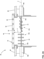
- FIG. 2A depicts a more detailed view a portion of the upstream portion 45a of the duct 45 of ventilation system 15 of FIG. 2 .
- the illustration of FIG. 2A is similar to the non-limiting aspect of FIG. 2 , so like numbers will be used to reference like parts.
- the first and second louvers 31, 32 are illustrated as selectively oriented in different respective positions than depicted in FIG. 2 , respectively. More specifically, FIG. 2A depicts the set of first louvers 31 in the closed second position 31b, and the set of second louvers 32 in the open first position 32a.
- the set of first louvers 31 and the set of second louvers 32 can be aligned with each other across a width of the duct 45 at a common longitudinal distance "L" from the cooking surface 20.
- the set of first louvers 31 and the set of second louvers 32 can be arranged to rotate around a respective axis (not shown) defined at a common longitudinal distance "L" from the cooking surface 20.
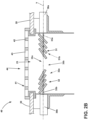
- FIG. 2B depicts the same portion of the ventilation system 15 of FIG. 2A , with the first and second louvers 31, 32 oriented in different relative positions than in FIG. 2A . More specifically, FIG. 2B depicts both the set of first louvers 31 and the set of second louvers 32 selectively oriented in the closed second position 31b, 32b.
- the set of first louvers 31 and the set of second louvers 32 can be arranged within the duct 45 such that when disposed in the respective second positions 31b, 32b, the first and second louvers 31, 32 can cooperatively form or define a converging section 38a (e.g. a venturi inlet) and forms a diverging section 38b (e.g., a venturi outlet).
- the set of first louvers 31 and the set of second louvers 32 disposed within the duct 45 can cooperatively defines a fluid flow path that can exhibit characteristics similar to or the same as a typical venturi device.
- first louvers 31 and the set of second louvers 32 are illustrated in FIGS 2 , 2a , and 2b and described herein, for ease of description and understanding, as selectively and independently moveable between the respective first position 31a, 32a and second position 31b, 32b, it is contemplated that in other non-limiting aspects are not so limited. In other aspects, the set of first louvers 31 and the set of second louvers 32 can be arranged to be moveable between any number of respective positions, without departing from the scope of the disclosure herein.
- At least one of the set of first louvers 31 and the set of second louvers 32 can be moveable between a first position 31a, 32a (e.g., an open position) and a second position 31b, 32b (e.g., a closed position) through a number of partially open, or partially closed positions (not shown).
- the first louver positioning motor 36a can be arranged to selectively move or rotate the set of first louvers 31 between the first position 31a (e.g., an open position) and the second position 31b (e.g., a closed position).
- the second positioning motor 36b can be arranged to selectively move or rotate the set of second louvers 32 between the first position 32a (e.g., an open position) and the second position 32b (e.g., a closed position).
- the orientation of the set of first louvers 31 and the set of second louvers 32 can function to optimize the airflow 19 into the duct 45 to advantageously affect cooking operations and the capture capacity of the ventilation system 15.
- blower 70 is depicted as disposed within the duct 45, other aspects are not so limited.
- the blower 70 can be disposed outside the duct 45, such as in a plenum chamber (not shown) in fluid communication with the duct 45.
- the blower 70 can be a conventional blower 70 comprising rotatable fan blades (not shown).
- the blower 70 can be configured to have a single speed of rotation of the fan blades speed of the blower 70.
- the blower 70 can be selectively adjustable between an OFF state, and a first blower speed.
- the blower 70 can have a blower speed that is selectable or adjustable between at least first speed (e.g., a low speed) and a second speed (e.g., a high speed). In such aspects, the blower 70 can be selectively adjustable between an OFF state, and the first speed, and the second speed. As will be described in more detail herein, the speed of the blower 70 can be selected or adjusted based on a desired speed or airflow volume of the airflow 19 through the duct 45, the position of the set of first louvers 31, or the position of the set of second louvers 32, or combinations thereof to optimize the airflow 19 into the duct 45 to advantageously affect cooking operations and the capture capacity of the ventilation system 15.
- first speed e.g., a low speed
- a second speed e.g., a high speed
- the blower 70 can be selectively adjustable between an OFF state, and the first speed, and the second speed.
- the speed of the blower 70 can be selected or adjusted based on a desired speed or airflow
- the blower 70 can include a housing 73 that has a top or upstream portion 73a and a bottom or downstream portion 73b.
- the blower 70 upstream portion 73a can define an opening or air inlet 78.
- the air inlet 78 can be configured to receive the airflow 19 therethrough, which can contain smoke and fumes created during the cooking process.
- An inlet screen (not shown) can optionally be disposed across the air inlet 78 to prevent physical objects from going into the blower 70 or housing 73.
- the blower 70 downstream portion 73b can define an opening or air outlet 79.
- the air outlet 79 can be configured to discharge the airflow 19 therethrough from the blower 70.
- the blower 70 can include a power inlet or conduit box (omitted for clarity) and a blower motor speed control 77 for receiving electrical power to operate the blower motor 76.
- the blower motor speed control 77 can be communicatively coupled to the controller module 80 and the blower motor 76.
- the blower motor speed control 77 can be configured to control adjust the power (e.g., current) provided to the blower motor 76, in response to a speed control signal 88 from the controller module 80 to thereby adjust or regulate the blower motor 76 speed in a known manner.
- the blower motor 76 can be any conventional motor such as a permanent-split capacitor ("PSC") motor.
- the blower motor 76 can be a capacitor start and run motor comprising a starting capacitor inserted in series with the startup windings or second windings (not shown) connected to a power source, e.g., 120 Volts, 60 Hertz. (not shown).
- the blower motor 76 can be an electronically commutated (EC) motor, having its speed regulated via the blower motor speed control 77 via conventional pulse width modulation (PWM) techniques.
- PWM pulse width modulation
- Other aspects are not so limited, and the blower motor 76 can be any desired motor, operating at any desired power, using any desired motor speed controller without departing from the scope of the disclosure.
- the filter 48 can be disposed in the duct 45 upstream of the blower 70.
- the filter 48 can a conventional filter.
- the filter 48 can be mounted at an angle with respect to the longitudinal axis X to enable runoff of any grease or other unwanted materials from the filter 48.
- the set of sensors 60 can be disposed in various locations within the cooking appliance 10 and communicatively coupled to the controller module 80.
- the set of sensors 60 can configured to sense, detect, measure, or otherwise determine a value of a respective second parameter 62.
- the sensors 60 can comprise any desired conventional sensor 60 including, but not limited to, a temperature sensor, a humidity sensor, a pressure sensor, a light sensor, a photo-electric sensor, a proximity sensor, a voltage sensor, a current sensor, a chemical sensor, a moisture sensor, an airflow sensor, a switch sensor, an odor sensor, a smoke detector, or combinations thereof.
- the sensors 60 can be arranged to provide a respective second signal 82 to the controller module 80 indicative of a value of a second parameter 62.
- the value of the second parameter 62 can be indicative of a status of the cooking appliance 10 or the ventilation system 15 or both.
- the set of sensors 60 can be configured to provide a respective second signal 82 to the controller module 80 indicative of the respective sensed or measured value of the second parameters 62 detected or measured by the sensors 60.
- the controller module 80 can be coupled in signal communication with the user interface 50 to receive the first signal 81 therefrom.
- the controller module 80 can also receive the second signal 82 from the set of sensors 60.
- the controller module 80 can be further communicatively coupled to the first louver positioning motor 36a, to provide a first position control signal 87a thereto.
- the controller module 80 can be further communicatively coupled to the second louver positioning motor 36b, to provide a second position control signal 87b thereto.
- the controller module 80 can be further communicatively coupled to the blower motor 46, to provide a speed control signal 88 thereto.
- the controller module 80 can be disposed within the cooking appliance 10 in any desired location without departing from the scope of the disclosure herein. Alternatively, it is contemplated that the controller module 80 can be configured for wireless communication with the ventilation system 15, and can be disposed remote from the appliance 10 without departing from the scope of the disclosure.
- the memory 85 can be configured to store a set of desired values 86.
- the set of desired values 86 can include predetermined desired values 86 associated with or corresponding to a predetermined optimal condition or desired status of the cooking appliance 10, the ventilation system, or both.
- the set of desired values 86 can be indicative of various target or desired speeds of the blower 70, desired positions of the first louvers 31, or desired positions of the second louvers 32, or combinations thereof.
- the target or desired speeds of the blower 70, positions of the first louvers 31, or positions of the second louvers 32, or combinations thereof can be based on the desired values 86.
- the target or desired speeds of the blower 70 can include an OFF condition of the blower, a first speed of the blower 70, or a second speed of the blower 70.
- the desired positions of the first louvers 31 can include the first position 31a, and the second position 32b.
- the desired positions of the second louvers 32 can include the first position 32a, and the second position 32b.
- the desired values 86 can also include default settings for the blower speed 70, or default positions of the first louvers 31 or second louvers 32, or combinations thereof during an operation of the cooking appliance 10.
- the set of desired values 86 can include calculated desired values 86 associated with or corresponding to a predetermined optimal condition or desired status of the cooking appliance 10, the ventilation system, or both.
- the processor can be configured to calculate, estimate, or otherwise determine the set of desired values 86 in real-time.
- the desired values 86 can be selectable by the controller module 80 from the memory 85, or calculated, estimated, or otherwise determined by the processor 84, or both, based on the user inputs 53 received from the user interface 50, or values of respective second parameters 62 received from the set of sensors 60, or combinations thereof.
- cooking emissions 18 e.g., steam
- hot ambient air 16 proximal to the vessel 17 and cooking surface 20 can be drawn into the airflow 19 and through the exhaust inlet portion 44 into the duct 45 using the blower 70.
- the blower 70 By selectively positioning the first and second sets of louvers 31, 32, or adjusting the blower speed, or a combination thereof, based on one or more user inputs 53 and sensed or measured second parameters 62, the fluid flow characteristics of the cooking emissions 18 and ambient air 16 into and through the duct 45, can be optimized.
- aspects as described herein can result in an improved capture efficiency of the ventilation system 15, improved temperature control of the cooking appliance 10, and more efficient heating and stable cooking temperatures can be obtained, compared to conventional cooking appliances with typical downdraft venting arrangements.
- the rate of rise of a temperature of a cooking vessel 17 can be better controlled to reduce stresses on the cooking vessel 17 that would result from an undesirably rapid temperature increase.
- the volatility of temperature swings during a cooking operation such as a "searing event" can be reduced.
- non-limiting aspects as described herein can prevent an undesired reduction of a cooking temperature by selectively adjusting or reducing the speed, volume, or direction of a flow of cool air proximal the cooking vessel.
- non-limiting aspects can also prevent an undesired increase in a cooking temperature by selectively adjusting or increasing the speed, volume, or direction of a flow of cool air proximal the cooking vessel 17.
- non-limiting aspects can be operative to enable selective adjustment at least one of the speed, volume, or direction of the airflow 19 to thereby stabilize the temperature of the cooking surface 20 or cooking vessel 17 or both.
- a user may desire to heat a food item (not shown), for example placed in the vessel 17 such as a pot located on a heatable portion 21a-21d of the cooking surface 20, or a food item (not shown) located on a heatable portion 21a-21d (such as a grill portion) of the cooking surface 20.
- the user can manually select or otherwise provide the user input 53 indicative of a value of one or more first parameters 51, such as a heat setting, via the user interface 50.
- the user interface 50 can provide the first signal 81 indicative of the value of the first parameters 51 to the controller module 80.
- the controller module 80 can store the value of the first parameters 51 in the memory 85.
- the value of the first parameters 51 can include a relative heat setting (e.g., a low, a medium, or a high heat) for a particular heatable portion 21a-21d of the cooking surface 20.
- the value of the first parameters 51 can include a particular temperature for a particular heatable portion 21a-21d of the cooking surface 20.
- the user input 53 can be indicative of a respective value of a set of first parameters 51.
- the set of first parameters 51 can additionally or alternatively include, without limitation, one or more of a user-selected blower speed (e.g., a low, a medium, or a high speed), a selected heatable portion 21a-d, a selected heat source 22a-d, a food type (e.g., meat, soup, etc.), a food state (e.g., liquid, frozen, etc.), a vessel type (e.g., a pot, a grill, etc.), a vessel material (e.g., steel, cast iron, ceramic, etc.), a cooking time duration, (e.g., 1-hour) a cooking operation (boil, simmer, etc.), and combinations thereof.
- a user-selected blower speed e.g., a low, a medium, or a high speed
- a selected heatable portion 21a-d e.g., meat, soup, etc.
- a selected heat source 22a-d e.g., a selected heat source
- the set of sensors 60 can provide the set of second signals 82 to the controller module 80 indicative of a measured or detected value of one or more of the set of respective second parameters 62.
- the set of second parameters 62 can include, without limitation, a temperature (e.g., of air) within the duct 45, an ambient temperature external to the duct 45, a relative humidity within the duct 45, a relative humidity external to the duct 45, an airflow volume within the duct 45, an air pressure within the duct 45, an air pressure external to the duct 45, a relative amount of a volatile organic compound (VOC) in the duct 45, a temperature of the cooking surface 20, a temperature of the cooking vessel 17, a change in the temperature of the cooking vessel 17, a position of the set of first louvers 31, a position of the set of second louvers 32, a speed of the blower 70, a status of one or more of the heat sources 22a-22d, a temperature of one or more of the heatable portions 21a-21d,
- VOC volatile organic compound
- the processor 84 can select the set of desired values 86 from the memory 85 based on the first signal 81 and the second signal 82. Additionally, or alternatively, the processor 84 can calculate or otherwise determine the set of desired values 86, or both, based on the first signal 81 and the second signal 82. For example, the controller module 80 can determine the value of the first parameters 51 and the value of the second parameters 62, based on the first and second signals 81, 82, respectively. The desired values 86 can then be selected from memory 85 by the controller module 80 based on the determined values of the first parameters 51, or the value of the second parameters 62, or a combination thereof.
- the desired values 86 can also be calculated or otherwise determined by the processor 84, based on the value of the first parameters 51, or the value of the second parameters 62, or a combination thereof.
- the processor 84 can be configured to perform a comparison of the value of the first parameters 51 with the value of the second parameters 62 and based on the comparison, select the desired values 86 from memory 85.
- the set of desired values 86 can additionally or alternatively be calculated or estimated, by the controller module 80 based on predetermined ratios, algorithms, equations, look-up tables, or the like, based on the value of the first parameters 51, or the value of the second parameters 62, or a combination thereof.
- the controller module 80 can further determine a target or desired speed of the blower 70, a desired position of the first louvers 31, or a desired position of the second louver 32, or a combination thereof. In non-limiting aspects, the controller module 80 can further execute a comparison of the desired values 86, with a current speed of the blower 70, a current position of the first louvers 31, or a current position of the second louver 32, respectively. Based on the comparison, the controller module 80 can determine whether the current speed of the blower 70 or position of the first and second louvers 31, 32 satisfies the desired values 86.
- the controller module 80 can further trigger an adjustment or change in the speed of the blower 70, position of the set of first louvers 3, or position of the second set of louvers 32, or a combination thereof.
- the controller module 80 can provide the speed control signal 88 to the blower motor speed control 77, the first position control signal 87a to the first louver positioning motor 36a, or the second position control signal 87b to the second louver positioning motor 36b or combinations thereof.
- the speed control signal 88 can cause the blower motor speed control 77 to adjust the speed of the blower motor 76 to satisfy with the desired values 86.
- the first position control signal 87a can cause the first position control motor 36 to adjust to adjust or change the position of the set of first louvers 31 to satisfy the desired values 86.
- the second position control signal 36b can cause the second position control motor 36 to adjust to adjust or change the position of the set of second louvers 32 to satisfy the selected desired values 86.
- FIG. 4 illustrates an additional layout scheme of a further embodiment of the cooking appliance 10 in accordance with a non-limiting aspect of the present disclosure.
- the cooking appliance 10 as shown in FIG. 4 is a cooktop having a cooking surface 20 and a downdraft ventilation system 15 similar to the ventilation system already disclosed with reference to figures 1 and 2 .
- the downdraft ventilation system 15 can comprise a ventilator, a user interface (not shown) and a set of sensors 60, shown in FIG.5 .
- the cooking surface 20 can include a set of heated or heatable portions 21a-21d such as a first heatable portion 21a, a second heatable portion 21b, a third heatable portion 21c, and a fourth heatable portion 21d.
- the heatable portions 21a-21d can be proximal to, and heated by a respective heat source (e.g., gas, resistive coil, inductive coil and the like), which can be located on or under the cooking surface 20.
- a respective heat source e.g., gas, resist
- the cooking surface 20 can define a vent opening 23 therethrough, preferably located alongside the heatable portions 21a-21d of the cooking surface 20.
- the downdraft ventilation system 15 is therefore installed adjacent to the cooking area and positioned adjacent to or coupled with the cooking appliance 10 so that to be able to capture and exhaust cooking emissions emanating from the cooking appliance 10.
- the user interface can be disposed as in the embodiment shown in FIG.1 or at any desired location, or at a combination of locations, on or remote from the appliance 10 or on a remote or mobile device (not shown), and communicatively coupled to the downdraft ventilation system 15.
- the set of sensors 60 can be disposed on or supported by the cooking surface 20 or in any other desired location, such as inside the downdraft ventilation system 15 ( FIG.5 ) without departing from the scope of the disclosure herein.
- FIG. 5 and FIG. 6 show different cutaway schemes of the downdraft ventilation system 15 of the cooking appliance 10 shown in FIG.4 , each with some parts shown in a schematic form, for ease of description and understanding.
- additional elements of the ventilation system 15, not visible in FIG. 4 are shown.
- Such additional elements can include the duct 45, a blower 70 and a corresponding blower motor 76.
- a blower motor speed control (not shown) can be included in the duct 45.
- the blower motor 76 of the blower 70 has a speed of operation selectable between at least a first speed and a second speed wherein the blower is active into the duct 45 and is operative to draw the airflow 19 through such duct 45.
- At least one set of louvers 31, 32 are disposed in the duct 45 downstream or in correspondence of the vent opening 23 and is selectively movable between a closed position, wherein the airflow 19 cannot flow through the at least one set of louvers 31, 32 and a plurality of open positions wherein a corresponding opening size of the at least one set of louvers 31, 32 changes and the airflow 19 can flow through the set of louvers 31, 32.
- at least one louver positioning motor 36a, 36b is coupled to the corresponding at least one set of louvers 31, 32 and is operative to selectively move the corresponding at least one set of louvers 31, 32 between the closed position and the open positions.
- the at least one set of louvers 31, 32 illustrated in FIG.4 , comprises two set of louvers 31, 32, namely a first set of louvers 31 and a second set of louvers 32, each of them is movable between a closed position, wherein the airflow 19 cannot flow through the corresponding set of louvers 31, 32 and a plurality of open positions wherein a corresponding opening size changes and the airflow 19 can flow through the corresponding set of louvers 31, 32.
- one specific louver positioning motor 36a, 36b namely a first louver positioning motor 36a and a second louver positioning motor 36b, is coupled to each corresponding set of louvers 31, 32 and is operative to selectively move the corresponding set of louvers 31, 32 between the closed and open position.
- each set of louvers 31, 32 corresponds to at least one region R of the cooking surface 20 of the cooking appliance 10 wherein at least one heatable portion 21a, 21b, 21c, 21d is included.
- each set of louvers 31, 32 corresponds to a region R of the cooking surface 20 having two heatable portions 21a, 21b, 21c, 21d substantially aligned between them and substantially aligned with the corresponding set of louvers 31, 32.
- the first set of louvers 31 is coupled to the first louver positioning motor 36a and is aligned with a couple of heatable portions 21a, 21b of a corresponding region R of the cooking appliance 10, while the second set of louvers 32 is couple to the second louver positioning motor 36b and is aligned with another couple of heatable portions 21c, 21d of an adjacent region R of the cooking appliance 10.
- the duct 45 comprises and defines an upstream portion 45a and an opposite downstream portion 45b.
- the upstream portion 45a is in fluid communication with the opening 23.
- the duct 45 has a transversal cross-section the size of which changes along the longitudinal development of the duct 45 between the upstream portion 45a and the downstream portion 45b.
- the duct 45 also comprises at least one body portion 45c wherein the transversal cross-section presents a size reduction, optionally a region or point of maximum cross-section reduction.
- the body portion 45c of the duct 45 is interposed between the upstream portion 45a and the downstream portion 45b.
- the transversal cross-section of the duct 45 decreases, optionally constantly, from the upstream portion 45a to the body portion 45c and increases, optionally constantly, from the latter to the downstream portion 45b.
- the transversal cross-section decrease in the upstream portion 45a is more pronounced than the transversal cross-section increase in the downstream portion 45b.
- the blower 70 is located into the duct 45 in correspondence of the downstream portion 45b of the latter.
- the blower 70 is close to the body portion 45c, whereas in FIG.6 , the blower 70 is located far away from the body portion 45c.
- the blower 70 When the blower 70 is activated, it draws an airflow 19 through the duct 45 from the vent opening 23 and the upstream portion 45a to the downstream portion 45b.
- At least one deflection blade B is also provided.
- the deflection blade B is operatively located into the duct 45 downstream the vent opening 23 and/or the first and the second set of louvers 31, 32 to act on the airflow 19 flowing along the duct 45 from the upstream portion 45a to the downstream portion 45b, in particular in order to prevent undesired temperature changes of at least one cooking vessel 17, particularly temperature reduction, by controlling the airflow path around/near such a cooking vessel 17 being used for cooking.
- the deflection blade B is located upstream the blower 70 and, advantageously, it is located close to or in correspondence of the body portion 45c of the duct 45.
- the deflection blade B is directionable inside the duct 45 to modify the airflow path therethrough. More specifically, deflection blade B is swivelling among a plurality of relative positions wherein the corresponding lying plane of the deflection blade B changes orientation with respect to at least one of the three orthogonal axis X, Y, Z of the duct 45, namely a longitudinal axis X, a first transversal axis Y, perpendicular to the longitudinal axis X and a second transversal axis Z, perpendicular to the longitudinal axis X and the first transversal axis X.
- the deflection blade B is directionable among: three particular relative positions, wherein two of the three orthogonal axis X, Y, Z of the duct 45 stand on the lying plane of the deflection blade B, being the latter perpendicular with respect to the resting orthogonal axis; a plurality first relative positions, wherein only one of the three orthogonal axis X, Y, Z of the duct 45 stands on the lying plane of the deflection blade B being the latter inclined with respect to the other two orthogonal axis X, Y, Z; and, at least one second relative position, wherein the deflection blade B is inclined with respect to all the orthogonal axis X, Y, Z of the duct 45.
- the directionable blade B can be oriented inside the duct 45 in order to modify the airflow 19 from the upstream 45a to the downstream 45b by influencing both the airflow 19 outgoing from the downstream portion 45b and the ingoing airflow 19 sucked through the vent opening 23 and at least one set of louvers 31, 32, when opened.
- FIG.4 the embodiment of FIG.4, FIG.5 and FIG.6 is provided with a controller module 80 ( FIG.5 ).
- the controller module 80 is communicatively coupled to the blower motor 76 and to the first and/or to the second set of louvers 31, 32.
- the controller module is configured to receive a first signal 81 indicative of a value of a first parameter 51 from the user interface 50, receive a second signal 82 indicative of a measured value of a second parameter 62 from a sensor 60 and trigger at least one of a change in the speed of operation of the blower motor 76 and a change in the position of at least one of the set of louvers 31, 32, based on the value of the first parameter 51 and of the second parameter 62.
- controller module 80 is also communicatively coupled with the deflection blade B and is configured to trigger a change in the position and/or orientation of the deflection blade B, optionally based on the value of the first parameter 51 and of the second parameter 62, independently or in addition to trigger at least one of a change in the speed of operation of the blower motor 76 and a change in the position of at least one of the set of louvers 31, 32.
- the controller module 80 maintains a temperature stabilization of at least one cooking vessel 17 by controlling one or more of the following: speed of operation of the blower motor 76; opening size of at least one set of louvers 31, 32; and, position and/or orientation of the deflection blade B.
- the controller module 80 works in the same manner of the one used for the embodiment of FIG.1 and FIG.2 , with the difference that the controller module 80 also interacts with the deflection blade B to manage the position and/or orientation of the latter inside the duct 45.
- the controller module 80 is further configured to select a set of predetermined desired values from a memory based on the value of the first parameter 51 and the value of the second parameter 62. Additionally or alternatively, the controller module 80 is configured to calculate a set of desired values based on the value of the first parameter 51 and the value of the second parameter 62. The at least one of the change in the blower motor 76 speed of operation and/or in the position of the first and second set of louvers 31, 32 and/or in the position and/or orientation of the deflection blade B inside the duct 45 can be based on the set of predetermined desired values.
- the downdraft ventilation system 15 of the cooking appliance 10 comprises at least one filter 48 disposed into the duct 45 and in fluid communication with the airflow 19 through the duct 45.
- the filter 48 is located inside the duct 45 downstream at least one of the set of louvers 31, 32 and upstream or downstream the blower 70.
- the cooking appliance 10 can be provided with two filters 48 both located inside the duct 45, wherein at least one of the two filters 48 is located downstream the blower 70.
- the filters 48 are made of the same filtering material. However, it is also possible to consider filters 48, made of different filtering materials.
- the user selection is at least one of a temperature, optionally a cooking vessel 17 temperature, a blower motor speed, an opening size of the at least one of the set of louvers 31, 32 and a position and/or orientation of the deflection blade B inside the duct 45.
- the first parameter 51 can include a heat setting while the second parameter 62 can include at least one of a temperature of air within the duct 45, an ambient temperature external to the duct 45, a relative humidity within the duct 45, a relative humidity external to the duct 45, an airflow volume within the duct 45, an air pressure within the duct 45, and air pressure external to the duct 45, a relative amount of a volatile organic compound VOC in the duct 45, a temperature of the cooking surface 20, a temperature of a cooking vessel 17, a change in the temperature of the cooking vessel 17, the position of the at least one set of louvers 31, 32, the blower motor 76 speed of operation and the position and/or the orientation of the deflection blade B.
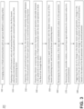
- FIG. 3 illustrates a non-limiting example of a method 300 of to ventilate a cooking appliance 10, for example using the ventilation system 15 of FIG. 2 .
- the ventilation system 15 is described herein in terms of a cooking appliance 10, it will be appreciated that the method 300 can be applied to any suitable appliance or ventilation system. While the method 300 will be described with reference to the ventilation system 15 and cooking appliance 10 of FIG. 2 , other aspects are not so limited and the method 300 can be implemented using any other ventilation system 15 and cooking appliance 10 without departing from the scope of the disclosure herein.
- the method 300 can begin at step 310, by arranging the duct 45 in fluid communication with the vent opening 23 defined in the cooking surface 20 of the cooking appliance 10.
- the method 300 can include, at step 320, disposing the set of first louvers 31 in the duct 45 and at step 330 disposing the set of second louvers 32 in the duct 45.
- the set of first louvers 31 and the set of second louvers 32 can be independently moveable between at least two respective positions to independently or cooperatively enable, limit, regulate, or redirect the airflow 19, and combinations thereof.
- the set of first louvers 31 can be selectively movable between the first position 31a (e.g., an open position) and the second position 31b (e.g., a closed position).
- the set of second louvers 32 can be selectively movable between the first position 32a (e.g., an open position) and the second position 32b (e.g., a closed position).
- the first positioning motor 36a can be arranged to selectively move or rotate the set of first louvers 31 between the first position 31a and the second position 31b.
- the second positioning motor 36b can be arranged to selectively move or rotate the set of second louvers 32 between the first position 32a and the second position 32b.
- the method 300 can include, at step 340, disposing a blower 70, in fluid communication with the duct 45 and operative to draw the flow of air 19 through the duct.
- the blower 70 can comprise a blower motor 76 having a speed of operation selectable between a first speed and a second speed.
- the blower 70 can be disposed downstream of the set of first louvers 31 and second set of louvers.
- the blower 70 can be in fluid communication with the duct 45 and the air space 24 above the cooking surface 20.
- the blower 70 can include a motor speed controller 77 to receive electrical power to operate the blower motor 76.
- the method can continue, at step 450, by coupling a controller module 80 in signal communication with the blower motor 76, the set of first louver positioning motor 36a, and the second louver positioning motor 36b.
- the method can include receiving by the controller module 80, a first signal 81 indicative of a value of a first parameter 51, and at step 470, receiving by the controller module 80, a second signal 82 indicative of a measured a value of a second parameter 62.
- the method 300 can include, at 480, triggering at least one of a change in the blower motor 76 speed of operation, a change in the position of the set of first louvers 31, and a change in the position of the set of second louvers 32, based on the value of the first parameter 51 and the value of the second parameter 62.
- the sequence depicted is for illustrative purposes only and is not meant to limit the method 300 in any way as it is understood that the portions of the method can proceed in a different logical order, additional or intervening portions can be included, or described portions of the method can be divided into multiple portions, or described portions of the method can be omitted without detracting from the described method.
- a cooking appliance comprising a cooking surface having a vent opening defined therethrough, a duct arranged to convey an airflow therethrough and defining an upstream portion and a downstream portion, the duct in fluid communication with the opening, a set of first louvers and a set of second louvers disposed in the duct downstream of the vent opening, a first louver positioning motor coupled to the set of first louvers operative to selectively move the set of first louvers between a first position and a second position, a second louver positioning motor coupled to the set of second louvers operative to selectively move the set of second louvers between a third position and a fourth position, a blower comprising a blower motor having a speed of operation selectable between at least a first speed and a second speed, the blower in fluid communication with the duct and operative to draw the airflow through the duct from the upstream portion to the downstream portion, a controller module communicatively coupled to the blower motor, the first louver positioning motor coupled to the set of first louvers and a set
- the controller module configured to receive a first signal indicative of a value of a first parameter from a user interface, receive a second signal indicative of a measured value of a second parameter from a sensor, and trigger at least one of a change in the blower motor speed of operation, a change in the position of the set of first louvers, and a change in the position of the set of second louvers, based on the value of the first parameter and the second parameter.
- controller module is further configured to select a set of predetermined desired values from a memory based on the value of the first parameter and the value of the second parameter, and wherein the at least one of the change in the blower motor speed of operation, the change in the position of the set of first louvers, and the change in the position of the set of second louvers is based on the set of predetermined desired values.
- controller module is further configured to calculate a set of desired values based on the value of the first parameter and the value of the second parameter, and wherein the at least one of the change in the blower motor speed of operation, the change in the position of the set of first louvers, and the change in the position of the set of second louvers is based on the set of desired values.
- the cooking appliance of any of the preceding clauses further comprising a filter disposed in the duct and in fluid communication with the airflow through the duct.
- the temperature is a cooking vessel temperature.
- the second parameter includes at least one of a temperature of air within the duct, an ambient temperature external to the duct, a relative humidity within the duct, a relative humidity external to the duct, an airflow volume within the duct, an air pressure within the duct, and air pressure external to the duct, a relative amount of a volatile organic compound (VOC) in the duct, a temperature of the cooking surface, a temperature of a cooking vessel, a change in the temperature of the cooking vessel, the position of the set of first louvers, the position of the set of second louvers, and the blower motor speed of operation.
- VOC volatile organic compound
- the cooking appliance of any of the preceding clauses further comprising a set of sensors communicatively coupled to the controller module, wherein the second signal is provided via the set of sensors.
- a ventilation system comprising a duct arranged to convey an airflow therethrough and defining an upstream portion and a downstream portion, the duct in fluid communication with a vent opening defined in a cooking surface, a set of first louvers and a set of second louvers disposed in the duct downstream of the vent opening, a first louver positioning motor coupled to the set of first louvers operative to selectively move the set of first louvers between a first position and a second position, a second louver positioning motor coupled to the set of second louvers operative to selectively move the set of second louvers between a third position and a fourth position, a blower comprising a blower motor having a speed of operation selectable between at least a first speed and a second speed, the blower in fluid communication with duct and operative to draw the airflow through the duct from the upstream portion to the downstream portion, and a controller module communicatively coupled to the blower motor, the first louver positioning motor, and the second louver positioning motor.
- the controller module configured to receive a first signal indicative of a value of a first parameter from a user interface, receive a second signal indicative of a measured a value of a second parameter from a sensor, and trigger at least one of a change in the blower motor speed of operation, a change in the position of the set of first louvers, and a change in the position of the set of second louvers, based on the value of the first parameter and the second parameter.
- controller module is further configured to select a set of predetermined desired values from a memory based on the value of the first parameter and the value of the second parameter, and wherein the at least one of the change in the blower motor speed of operation, the change in the position of the set of first louvers, and the change in the position of the set of second louvers is based on the set of predetermined desired values.
- controller module is further configured to calculate a set of desired values based on the value of the first parameter and the value of the second parameter, and wherein the at least one of the change in the blower motor speed of operation, the change in the position of the set of first louvers, and the change in the position of the set of second louvers is based on the set of desired values.
- the ventilation system of any of the preceding clauses further comprising a filter disposed in the duct and in fluid communication with the airflow through the duct.
- the first parameter is at least one of a temperature and a blower motor speed.
- the second parameter includes at least one of a temperature of air within the duct, an ambient temperature external to the duct, a relative humidity within the duct, a relative humidity external to the duct, an airflow volume within the duct, an air pressure within the duct, and air pressure external to the duct, a relative amount of a volatile organic compound (VOC) in the duct, a temperature of the cooking surface, a temperature of a cooking vessel, a change in the temperature of the cooking vessel, the position of the set of first louvers, the position of the set of second louvers, and the blower motor speed of operation.
- VOC volatile organic compound
- the ventilation system of any of the preceding clauses further comprising a set of sensors communicatively coupled to the controller module, wherein the second signal is received from the set of sensors.
- a method of operating a cooking appliance comprising arranging a duct in fluid communication with an aperture defined in a cooking surface, to convey an airflow therethrough to define an upstream portion and a downstream portion, disposing a set of first louvers in the duct, the first louvers selectively moveable between a first position and a second position via a first louver positioning motor, disposing a set of second louvers in the duct, the second louvers selectively moveable between a third position and a fourth position via a second louver positioning motor, disposing a blower comprising a blower motor, having a speed of operation selectable between a first speed and a second speed, in fluid communication with the duct and operative to draw the airflow through the duct, coupling a controller module in signal communication with the blower motor, the set of first louver positioning motor, and the second louver positioning motor, receiving by the controller module, a first signal indicative of a value of a first parameter, receiving by the controller module, a second signal indicative of a measured a value
- the method of the preceding clause further comprising selecting, by the controller module, a set of predetermined desired values from a memory based on the value of the first parameter and the value of the second parameter, and wherein the triggering the at least one of the change in the blower motor speed of operation, the change in the position of the set of first louvers, and the change in the position of the set of second louvers, is based on the set of predetermined desired values.
- any of the preceding clauses further comprising calculating, by the controller module, a set of desired values from a memory based on the value of the first parameter and the value of the second parameter, and wherein the triggering the at least one of the change in the blower motor speed of operation, the change in the position of the set of first louvers, and the change in the position of the set of second louvers, is based on the set of desired values.
- the method has to comprise the steps of:
Landscapes
- Engineering & Computer Science (AREA)
- Chemical & Material Sciences (AREA)
- Combustion & Propulsion (AREA)
- Mechanical Engineering (AREA)
- General Engineering & Computer Science (AREA)
- Ventilation (AREA)
Abstract
A cooking appliance (10) comprises: a cooking surface (20) having a vent opening (23) defined therethrough; a duct (45) arranged to convey an airflow (19) therethrough and defining an upstream portion (45a) and a downstream portion (45b), wherein the duct (45) is in fluid communication with the opening (23); a blower (70) comprising a blower motor (76) having a speed of operation selectable between at least a first speed and a second speed wherein the blower (70) is active into the duct (45) and is operative to draw the airflow (19) through the duct (45) from the upstream portion (45a) to the downstream portion (45b); at least one deflection blade (B) operatively located into the duct (45) downstream the opening (23) and/or the at least one set of louvers (31, 32) to act on the airflow (19) flowing along the duct (45) from the upstream portion (45a) to the downstream portion (45b), wherein the deflection blade (B) I located upstream the blower (70).
Description
- The present disclosure generally relates to a cooking appliance and a method of operating the cooking appliance, and more specifically to a ventilation system for a cooking appliance.
- Many different types of cooking appliances produce smoke, steam, or other gaseous contamination during use. Often, it is considered beneficial to utilize some type of ventilation system to evacuate the air borne contamination, either upward through a venting hood or downward into a draft flue. In kitchens, most known venting arrangements take the form of a hood which is fixed above a cooking surface and which can be selectively activated to evacuate the contaminated air. Downdraft vent arrangements are also commonly used with a cooking surface that incorporates a vent opening that is positioned between different sections of the cooking surface or extends along a back of the cooking surface. The downdraft vents can either be fixed relative to the cooking surface or can be selectively raised relative to the cooking surface to an operating position.
- However, because of the natural tendency of cooking emissions to flow vertically upward from the cooking appliance, and because of the arrangement of downdraft vents adjacent to, but not above, the emission plume, improvements to the emission capture capability of downdraft ventilation systems is desirable.
- Document
DE102020124068A1 discloses a downdraft fan comprising a suction section in operative connection to a blower device. The suction section comprises at least two suction channels, each with one suction opening. The flow speed of the sucked air can be adjusted independently at the suction openings. - Document
DE102019125683A1 discloses an extractor hood system with an extractor hood and an operating device designed to display information to a user and to receive input from the user. The operating device is designed for at least one displayed piece of information to have at least one corresponding setting of the extractor hood. - Document JPH03207925A discloses a smoke exhausting device associated to a cooking hob with a plurality of burners. The smoke exhausting device comprises two or more louvers provided on a suction port of the cooking hob, the opening degree of the louvers being controlled depending on a burner to be used.
- In one aspect, the present disclosure relates to a cooking appliance. The cooking appliance can include a cooking surface having a vent opening defined therethrough, a duct arranged to convey an airflow therethrough defining an upstream portion and a downstream portion, the duct in fluid communication with the opening. A set of first louvers and a set of second louvers is disposed in the duct downstream of the vent opening, and a first louver positioning motor is coupled to the set of first louvers operative to selectively move the set of first louvers between a first position and a second position, and a second louver positioning motor coupled to the set of second louvers operative to selectively move the set of second louvers between a third position and a fourth position. The cooking appliance can also include a blower comprising a blower motor having a speed of operation selectable between at least a first speed and a second speed, the blower in fluid communication with duct and operative to draw the airflow through the duct from the upstream portion to the downstream portion. A controller module can be communicatively coupled to the blower motor, the first louver positioning motor, and the second louver positioning motor. The controller module is configured to: receive a first signal indicative of a value of a first parameter from a user interface, receive a second signal indicative of a measured a value of a second parameter from a sensor, and trigger at least one of a change in the blower motor speed of operation, a change in the position of the set of first louvers, and a change in the position of the set of second louvers, based on the value of the first parameter and the second parameter.
- In another aspect, the present disclosure relates to a ventilation system. The ventilation system can include a duct arranged to convey an airflow therethrough and defining an upstream portion and a downstream portion, the duct in fluid communication with a vent opening defined in a cooking surface. The ventilation system can also include a set of first louvers and a set of second louvers disposed in the duct downstream of the vent opening; a first louver positioning motor coupled to the set of first louvers operative to selectively move the set of first louvers between a first position and a second position, and a second louver positioning motor coupled to the set of second louvers operative to selectively move the set of second louvers between a third position and a fourth position. The ventilation system can further include a blower comprising a blower motor having a speed of operation selectable between at least a first speed and a second speed, the blower in fluid communication with the duct and operative to draw the airflow through the duct from the upstream portion to the downstream portion; and a controller module communicatively coupled to the blower motor, the first louver positioning motor, and the second louver positioning motor. The controller module can be configured to: receive a first signal indicative of a value of a first parameter from a user interface, receive a second signal indicative of a measured value of a second parameter from a sensor, and trigger at least one of a change in the blower motor speed of operation, a change in the position of the set of first louvers, and a change in the position of the set of second louvers, based on the value of the first parameter and the second parameter.
- In yet another aspect, the present disclosure relates to a method of operating a cooking appliance. The method includes arranging a duct in fluid communication with an aperture defined in a cooking surface, to convey an airflow therethrough to define an upstream portion and a downstream portion, disposing a set of first louvers in the duct, the first louvers selectively moveable between a first position and a second position via a first louver positioning motor; disposing a set of second louvers in the duct, the second louvers selectively moveable between a third position and a fourth position via a second louver positioning motor. The method can also include disposing a blower comprising a blower motor, having a speed of operation selectable between a first speed and a second speed, in fluid communication with the duct and operative to draw the airflow through the duct; coupling a controller module in signal communication with the blower motor, the set of first louver positioning motor, and the second louver positioning motor; receiving by the controller module, a first signal indicative of a value of a first parameter; receiving by the controller module, a second signal indicative of a measured a value of a second parameter; and triggering at least one of a change in the blower motor speed of operation, a change in the position of the set of first louvers, and a change in the position of the set of second louvers, based on the value of the first parameter and the second parameter.
- In the light of the disclosure set out herein, and without in any way limiting the disclosure, in a 1st aspect, which may be combined with any one previous aspects or any other aspect or part thereof described herein, it is provided a cooking appliance (10) comprising: a cooking surface (20) having a vent opening (23) defined therethrough; a duct (45) arranged to convey an airflow (19) therethrough and defining an upstream portion (45a) and a downstream portion (45b) wherein the duct (45) is in fluid communication with the opening (23); at least one set of louvers (31, 32) disposed in the duct (45) downstream or in correspondence of the vent opening (23) wherein the at least one set of louvers (31, 32) is selectively movable between a closed position, wherein the airflow (19) cannot flow through the at least one set of louvers (31, 32) and a plurality of open positions wherein a corresponding opening size of the at least one set of louvers (31, 32) changes and the airflow (19) can flow through the set of louvers (31, 32), a blower (70) comprising a blower motor (76) having a speed of operation selectable between at least a first speed and a second speed wherein the blower (70) is active into the duct (45) and is operative to draw the airflow (19) through the duct (45) from the upstream portion (45a) to the downstream portion (45b); at least one deflection blade (B) operatively located into the duct (45) downstream the opening (23) and/or the at least one set of louvers (31, 32) to act on the airflow (19) flowing along the duct (45) from the upstream portion (45a) to the downstream portion (45b), a controller module (80) communicatively coupled to the blower motor (76) and to the at least one set of louvers (31, 32) wherein, the controller module (80) is configured to:
- receive a first signal (81) indicative of a value of a first parameter (51) from a user interface (50);
- receive a second signal (82) indicative of a measured value of a second parameter (62) from a sensor (60) and,
- trigger at least one of a change in the speed of operation of the blower motor (76) and a change in the position of the set of louvers (30, 31), based on the value of the first parameter (51) and of the second parameter (62).
- In a further independent aspect 1st bis, which can be combined with any one of the previous aspects and/or any one of the following aspects, it is provided a cooking appliance (10) comprising: a cooking surface (20) having a vent opening (23) defined therethrough; a duct (45) arranged to convey an airflow (19) therethrough and defining an upstream portion (45a) and a downstream portion (45b) wherein the duct (45) is in fluid communication with the opening (23); a blower (70) comprising a blower motor (76) having a speed of operation selectable between at least a first speed and a second speed wherein the blower (70) is active into the duct (45) and is operative to draw the airflow (19) through the duct (45) from the upstream portion (45a) to the downstream portion (45b); at least one deflection blade (B) operatively located into the duct (45) downstream the opening (23) and/or the at least one set of louvers (31, 32) to act on the airflow (19) flowing along the duct (45) from the upstream portion (45a) to the downstream portion (45b).
- In a further independent aspect 1st ter, which can be combined with any one of the previous aspects and/or any one of the following aspects, a ventilation system (15) comprising: a duct (45) arranged to convey an airflow (19) therethrough and defining an upstream portion (45a) and a downstream portion (45b) wherein the duct (45) is in fluid communication with a vent opening (23) defined in a cooking surface (20); at least one set of louvers (31, 32) disposed in the duct (45) downstream or in correspondence of the vent opening (23), wherein the at least one set of louvers (31, 32) is selectively movable between a closed position, wherein the airflow (19) cannot flow through the at least one set of louvers (31, 32) and a plurality of open positions wherein a corresponding opening size of the at least one set of louvers (31, 32) changes and the airflow (19) can flow through the at least one set of louvers (31, 32); a blower (70) comprising a blower motor (76) having a speed of operation selectable between at least a first speed and a second speed wherein the blower (70) is active into the duct (45) and is operative to draw the airflow (19) through the duct (45) from the upstream portion (45a) to the downstream portion (45b); at least one deflection blade (B) operatively located into the duct (45) downstream the opening (23) and/or the at least one set of louvers (31, 32) to act on the airflow (19) flowing along the duct (45) from the upstream portion (45a) to the downstream portion (45b), a controller module communicatively coupled to the blower motor (76) and to the at least one set of louvers (31, 32) wherein the controller module (80) is configured to:
- receive a first signal (81) indicative of a value of a first parameter (51) from a user interface (50), optionally a mobile user interface;
- receive a second signal (82) indicative of a measured value of a second parameter (62) from a sensor (60) and,
- trigger at least one of a change in the speed of operation of the blower motor (76) and a change in the position of the set of louvers, based on the value of the first parameter (51) and of the second parameter (62).
- In a further independent aspect 1st quater, which can be combined with any one of the previous aspects and/or any one of the following aspects, a ventilation system (15) comprising: a duct (45) arranged to convey an airflow (19) therethrough and defining an upstream portion (45a) and a downstream portion (45b) wherein the duct (45) is in fluid communication with a vent opening (23) defined in a cooking surface (20); a blower (70) comprising a blower motor (76) having a speed of operation selectable between at least a first speed and a second speed wherein the blower (70) is active into the duct (45) and is operative to draw the airflow (19) through the duct (45) from the upstream portion (45a) to the downstream portion (45b); at least one deflection blade (B) operatively located into the duct (45) downstream the opening (23) and/or the at least one set of louvers (31, 32) to act on the airflow (19) flowing along the duct (45) from the upstream portion (45a) to the downstream portion (45b).
- In a further independent aspect 1st quinquies, which can be combined with any one of the previous aspects and/or any one of the following aspects, a method of operating a cooking appliance (10) comprising the steps of: arranging a duct (45) in fluid communication with an aperture or a vent opening (23) defined in a cooking surface (20) to convey an airflow (19) therethrough to define an upstream portion (45a) and a downstream portion (45b); disposing at least one set of louvers (31, 32) in the duct (45) downstream or in correspondence of the vent opening (23), the at least one set of louvers (31, 32) being selectively moveable between a closed position, wherein the airflow (19) cannot flow through the at least one set of louvers (31, 32) and a plurality of open positions wherein a corresponding opening size of the at least one set of louvers (31, 32) changes and the airflow (19) can flow through the set of louvers (31, 32); disposing a blower (70) comprising a blower motor (76) having a speed of operation selectable between a first speed and a second speed, the blower (70) being active into the duct (45) and being operative to draw the airflow (19) through the duct (45); disposing at least one deflection blade (B) operatively located into the duct (45) downstream the opening (23) and/or the at least one set of louvers (31, 32) to act on the airflow (19) flowing along the duct (45) from the upstream portion (45a) to the downstream portion (45b); coupling a controller module (80) in signal communication with the blower motor (76), the louver positioning motor and/or the deflection blade (B); receiving by the controller module (80) a first signal (81) indicative of a value of a first parameter (51); receiving by the controller module (80) a second signal indicative of a measured value of a second parameter (62), and triggering at least one of a change in the speed of operation of the blower motor (76) and a change in the position of the set of louvers (31, 32) and/or change in the position and/or orientation of the deflection blade (B), wherein the step of triggering at least one of a change in the speed of operation of the blower motor (76) and a change in the position of the set of louvers (31, 32) is based at least on the value of the first parameter (51) and of the second parameter (62).
- In a further independent aspect 1st sexies, which can be combined with any one of the previous aspects and/or any one of the following aspects, it is provided a method of operating a cooking appliance (10) comprising the steps of: arranging a duct (45) in fluid communication with an aperture or a vent opening (23) defined in a cooking surface (20) to convey an airflow (19) therethrough to define an upstream portion (45a) and a downstream portion (45b); disposing a blower (70) comprising a blower motor (76) having a speed of operation selectable between a first speed and a second speed, the blower (70) being active into the duct (45) and being operative to draw the airflow (19) through the duct (45); disposing at least one deflection blade (B) operatively located into the duct (45) downstream the opening (23) and/or the at least one set of louvers (31, 32) to act on the airflow (19) flowing along the duct (45) from the upstream portion (45a) to the downstream portion (45b).
- In a 2nd according to any one of the previous aspects, the at least one deflection blade (B) is directionable inside the duct (45) to modify the airflow path therethrough.
- In a 3rd according to any one of the previous aspects, the at least one deflection blade (B) is swivelling among a plurality of relative positions wherein the corresponding lying plane changes orientation with respect to at least one of the three orthogonal axis (X, Y, Z) of the duct (45), namely a longitudinal axis (X), a first transversal axis (Y), perpendicular to the longitudinal axis (X) and a second transversal axis (Z), perpendicular to the longitudinal axis (X) and the first transversal axis (X).
- In a 4th aspect according to the previous aspect, the deflection blade (B) is directionable among:
- three particular relative positions, wherein two of the three orthogonal axis (X, Y, Z) of the duct (45) stand on the lying plane of the deflection blade (B) being the latter penpendicular to the remaining orthogonal axis of the duct (45);
- a plurality first relative positions wherein only one of the three orthogonal axis (X, Y, Z) of the duct (45) stands on the lying plane of the deflection blade (B) being the latter inclined with respect to the other two orthogonal axis (X, Y, Z); and,
- at least one second relative position wherein the deflection blade (B) is inclined with respect to all the orthogonal axis (X, Y, Z) of the duct (45).
- In a 5th aspect according to any one of the previous aspects, the deflection blade (B) is located upstream the blower (70).
- In a 6th aspect according to any one of the previous aspects, the cooking appliance (10) also comprises a controller module (80) communicatively coupled to the deflection blade (B) and configured to trigger a change in the position and/or orientation of the deflection blade (B) inside the duct (45) among the plurality of particular relative positions and/or the first relative positions and/or the second relative positions.
- In an aspect 6th bis according to the previous aspect, a set of sensors (60) or at least one sensor (60), in particular a temperature sensor, is communicatively coupled to the controller module (80), the controller module (80) controlling the position and/or orientation of the deflection blade (B) on the base of at least one triggering signal emitted by the set of sensors (60) or the at least one sensor (60).
- In a 7th aspect according to any one of the two previous aspects, the controller module (80) is configured to:
- receive a first signal (81) indicative of a value of a first parameter (51) from a user interface (50) optionally a mobile user interface (50);
- receive a second signal (82) indicative of a measured value of a second parameter (62) from a sensor (60) communicatively coupled to the controller mode (80), optionally a set of sensors (60) being communicatively coupled to the controller module (80) and the second signal (82) being provided via the set of sensors (60).
- In an 8th aspect according to the previous aspect, the controller module (80) is configured to trigger the position and/or orientation of the deflection blade (B) inside the duct (45), based on the value of the first parameter (51) and/or the second parameter (62).
- In a 9th aspect according to the two previous aspects, the controller module (80) is also communicatively coupled to the blower motor (76) to trigger at least one of a change in the speed of operation of the blower motor (76).
- In a 10th aspect according to the previous aspect, the controller module (80) is configured to trigger the speed of operation of the blower motor (76) based on the value of the first parameter (51) and/or the second parameter (62).
- In a 11th aspect according to any one of the previous aspects, the cooking appliance (10) comprises at least one set of louvers (31, 32) disposed in the duct (45) downstream or in correspondence of the vent opening (23), the at least one set of louvers (31, 32) being selectively movable between a closed position, wherein the airflow (19) cannot flow through the at least one set of louvers (31, 32) and a plurality of open positions wherein a corresponding opening size of the at least one set of louvers (31, 32) changes and the airflow (19) can flow through the set of louvers (31, 32).
- In a 12th aspect according to the previous aspects, the at least one set of louvers (31, 32) comprises two or more set of louvers (31, 32) each of them being movable between a closed position, wherein the airflow (19) cannot flow through the corresponding set of louvers (30,31) and a plurality of open positions wherein a corresponding opening size changes and the airflow (19) can flow through the corresponding set of louvers (31, 32).
- In a 13th aspect according to any one of the two previous aspects, at least one louver positioning motor (36a, 36b) is coupled to the corresponding at least one set of louvers (31, 32) and is operative to selectively move the corresponding at least one set of louvers (31, 32) between the closed position and more than one open position. In a 14th aspect according to any one of the three previous aspects, the at least one set of louvers (31, 32) comprises a set of first louvers (31) and a set of second louvers (32) each movable independently one with respect to the other, between a closed position, wherein the airflow (19) cannot flow through the corresponding set of louvers (30,31) and a plurality of open positions, wherein a corresponding opening size changes and the airflow (19) can flow through the corresponding set of louvers (31, 32).
- In a 15th aspect according to any one of the four previous aspects, it is provided that:
- a first louver positioning motor (36a) is coupled the set of first louvers (31) operative to selectively move the set of first louvers (31) between a first position (31a) and a second position (31b), optionally the first position can correspond to the closed position or to one of the plurality of the open positions of the set of the first louvers and the second position corresponding to one of the remaining open positions of the set of first louvers (31);
- a second louver positioning motor (36b) is coupled to a set of second louvers (32) operative to selectively move the set of second louvers (32) between a third position (32a) and a fourth position (32b), optionally the third position can correspond to the closed position or to one of the plurality of open positions of the set of second louvers (32) and the fourth position corresponding to one of the remaining open positions of the set of the second louvers (32).
- In a 16th aspect according to any one of the five previous aspects, each set of louvers (31, 32) corresponds to at least one region (R) of the cooking surface (20) of the cooking appliance (10) wherein at least one heatable portion (21a, 21b, 21c, 21d) is included, more in particular each set of louvers (31, 32) corresponding to a region (R) of the cooking surface (20) of the cooking appliance (10) having two heatable portions (21a, 21b, 21c, 21d) substantially aligned with the corresponding set of louvers (31, 32).
- In a 17th aspect according to any one of the six previous aspects, wherein the controller module (80) is communicatively coupled to the corresponding at least one set of louvers (31, 32) and is configured to trigger a change in the position of the corresponding at least one set of louvers (31, 32) between the closed position and the plurality of the open positions.
- In a 18th aspect according to any one of the seven previous aspects, wherein the controller module (80) is coupled to the louver positioning motor (36a, 36b) of the corresponding at least one set of louvers (31, 32) and is configured to trigger a change in position of the corresponding at least one set of louvers (31, 32) between the closed position and the plurality of the open positions.
- In a 19th aspect according to the 15th aspect or any one of the three previous aspects when depending on the 15th aspect, the controller module (80) is coupled to the first louver positioning motor (36a) of the set of first louvers (31) and the second louver positioning motor (36b) of the set of the second louvers (32) and is configured to trigger a change in the position of the set of first louvers (31) and/or a change in the position of a set of second louvers (32), between the closed position and the plurality of the open positions.
- In a 20th aspect according to any one of the three previous aspects, wherein the change in the position of the corresponding at least one set of louvers (31, 32) is carried out by the controller module (80) on the base of the value of the first parameter (51) and the second parameter (62).
- In 21st aspect according to the 7th aspect or any one of the thirteen previous aspects when depending on the 7th aspect, a set of sensors (60) is communicatively coupled to the controller module (80) and the second signal (82) is provided via the set of sensors (60).
- In a 22nd aspect according to the 9th aspect or any one of the twelve previous aspects when depending on the 9th aspect, the controller module (80) maintains a temperature stabilization of at least one cooking vessel (17) by controlling at least the speed of operation of the blower motor (76).
- In a 23rd aspect according to the 11th aspect or any one of the eleven previous aspects when depending on the 11th aspect, the controller module (80) maintains a temperature stabilization of at least one cooking vessel (17) by controlling at least the opening size of the at least one set of louvers (31, 32).
- In a 24th aspect according to the 6th aspect or any one of the nineteen previous aspects when depending on the 6th aspect, the controller module (80) maintains a temperature stabilization of at least one cooking vessel (17) by controlling at least the position and/or orientation of the deflection blade (B).
- In a 25th aspect according to any one of the previous aspects, the duct (45) comprises a transversal cross-section the size of which changes along the longitudinal development of the duct (45) between the upstream portion (45a) and the downstream portion (45b).
- In a 26th aspect according to the previous aspects, the duct (45) comprises at least one body portion (45c) wherein the transversal cross-section presents a size reduction, optionally a region or point of maximum cross-section reduction.
- In a 27th aspect according to the two previous aspects, the body portion (45c) of the duct (45) with the size reduction is interposed between the upstream portion (45a) and the downstream portion (45b).
- In a 28th aspect according to the three previous aspects, the deflection blade (B) is located close to or in correspondence of the body portion (45c) of the duct (45) with the size reduction.
- In a 29th aspect according to the four previous aspects, the transversal cross-section of the duct (45) decreases, optionally constantly, from the upstream portion (45a) to the body portion (45c) and increases, optionally constantly, from the latter to the downstream portion (45b).
- In a 30th aspect according to any one of the five previous aspects, the transversal cross-section decrease in the upstream portion (45a) is more pronounced than the transversal cross-section increase in the downstream portion (45b).
- In a 31st aspect according to any one of the previous aspects, the blower (70) is located in correspondence of the downstream portion (45b) of the duct (45).
- In a 32nd aspect according to the 7th aspect or any one of the twenty-five previous aspects when depending on the 7th aspect, the controller module (80) is further configured to select a set of predetermined desired values (86) from a memory (85) based on the value of the first parameter (51) and the value of the second parameter (62). In a 33rd aspect according to the 7th aspect or any one of the previous twenty-six aspects, the controller module (80) is further configured to calculate a set of desired values (86) based on the value of the first parameter (51) and the value of the second parameter (62).
- In a 34th aspect according to the 9th aspect or any one of the twenty-five previous aspects when depending on the 9th aspect, the at least one of the change in the blower motor (76) speed of operation is based on a set of predetermined desired values (86).
- In a 35th aspect according to the 11th aspect or any one of the twenty-four previous aspects when depending on the 11th aspect, the change in the position of the at least one set of louvers (31, 32) is based on a set of predetermined desired values (86).
- In a 36th aspect according to any one of the previous aspects, the cooking appliance (1) comprises a filter (48) disposed in the duct (45) and in fluid communication with the airflow (19) through the duct (45).
- In a 37th aspect according to the previous aspect when depending on the 11th aspect or any one of the aspects from the 12th aspect to the 35th when dependent on the 11th aspect, the filter (48) is located inside the duct (45) downstream the at least one set of louvers (31, 32).
- In a 38th aspect according to any one of the two previous aspects when depending on the 9th aspect or any one of the aspects from the 10th aspect to the 35th aspect when dependent on the 10th aspect, the filter (48) is located inside the duct (45) upstream the blower (70).
- In a 39th aspect according to any one of the aspects from the 36th aspect to the 37th aspect when depending on the 9th aspect or any one of the aspects from the 10th aspect to the 35th aspect when dependent on the 10th aspect, the filter (48) is located inside the duct (45) downstream the blower (70).
- In a 40th aspect according to any one of the aspects from the 36th aspect to the 37th aspect when depending on the 9th aspect or any one of the aspects from the 10th aspect to the 35th aspect when dependent on the 9th aspect, the cooking appliance (10) comprises at least two filters (48) located inside duct (45), wherein at least one of the two filters (48) is located downstream the blower (70), in particular the filters (48) being made by the same filtering material.
- In a 41st aspect according to any one of previous aspects from the 11th aspect to the 40th aspect, the user selection is at least one of a temperature, optionally a cooking vessel (17) temperature, a blower motor speed, an opening size of the at least one set of louvers (31, 32).
- In a 42nd aspect according to any one of the previous aspects, the user selection also comprises a position and/or orientation of the deflection blade (B).
- In a 43rd aspect according to the 6th aspect or any one of the thirty-seven previous aspects when depending on the 6th aspect, the first parameter (51) includes a heat setting and the second parameter (62) includes at least one of a temperature of air within the duct (45), an ambient temperature external to the duct (45), a relative humidity within the duct (45), a relative humidity external to the duct (45), an airflow volume within the duct (45), an air pressure within the duct (45), and air pressure external to the duct (45), a relative amount of a volatile organic compound (VOC) in the duct (45), a temperature of the cooking surface (20), a temperature of a cooking vessel (17), a change in the temperature of the cooking vessel (17), the position of the at least one set of louvers (31, 32) and the blower motor (76) speed of operation and/or the position and/or orientation of the deflection blade (B).
- In a 44th aspect according to any one of the previous aspects, the provision and/or the use of the deflection blade (B) inside the duct (45) prevents undesired temperature changes of at least one
cooking vessel 17, particularly temperature reduction, by controlling the airflow path around/near such acooking vessel 17 being used for cooking. - The invention will be described with a reference to the annexed figures. A brief description of the figures is hereinafter presented:
-
FIG. 1 illustrates a perspective view of a cooking appliance in accordance with a non-limiting aspect of the present disclosure. -
FIG. 2 illustrates a cutaway front view of the appliance ofFIG. 1 along the line 2-2, in accordance with a non-limiting aspect of the present disclosure. -
FIG. 2A illustrates a portion of a ventilation system with first and second louvers arranged in accordance with a non-limiting aspect of the present disclosure. -
FIG. 2B illustrates the portion of the ventilation system ofFIG. 2A depicting the first and second louvers arranged in accordance with another non-limiting aspect of the present disclosure. -
FIG. 3 illustrates a flowchart depicting exemplary steps of a method of ventilating a cooking appliance in accordance with a non-limiting aspect of the present disclosure. -
FIG. 4 illustrates and additional layout scheme of a further embodiment of the cooking appliance in accordance with a non-limiting aspect of the present disclosure. -
FIG. 5 schematically illustrates a first cutaway front view version of the cooking appliance ofFIG.4 . -
FIG.6 schematically illustrates a second cutaway front view version of the cooking appliance ofFIG.4 . - In describing aspects illustrated in the drawings, specific terminology will be resorted to for the sake of clarity. However, it is not intended that the aspects be limited to the specific terms so selected and it is to be understood that each specific term includes all technical equivalents that operate in a similar manner to accomplish a similar purpose. For example, the words "connected," "attached," "coupled," and "mounted" and variations thereof herein are used broadly and encompass direct and indirect connections, attachments, couplings, and mountings. In addition, the terms "connected," "coupled," etc. and variations thereof are not restricted to physical or mechanical connections, couplings, etc. as all such types of connections should be recognized as being equivalent by those skilled in the art.
- As used herein, the term "set" or a "set" of elements can be any non-zero number of elements, including only one. The exemplary drawings are for purposes of illustration only and the dimensions, positions, order and relative sizes reflected in the drawings attached hereto can vary.
- Additionally, as used herein, a "processor", or "controller module" can include a component configured or adapted to provide instruction, control, operation, or any form of communication for operable components to affect the operation thereof. A processor or controller module can include any known processor, microcontroller, or logic device, including, but not limited to: Field Programmable Gate Arrays (FPGA), an Application Specific Integrated circuit (ASIC),a Proportional controller (P), a Proportional Integral controller (PI), a Proportional Derivative controller (PD), a Proportional Integral Derivative controller (PID controller), a hardware-accelerated logic controller (e.g. for encoding, decoding, transcoding, etc.), the like, or a combination thereof. Non-limiting examples of a controller module can be configured or adapted to run, operate, or otherwise execute program code to effect operational or functional outcomes, including carrying out various methods, functionality, processing tasks, calculations, comparisons, sensing or measuring of values, or the like, to enable or achieve the technical operations or operations described herein. The operation or functional outcomes can be based on one or more inputs, stored data values, sensed or measured values, true or false indications, or the like. While "program code" is described, non-limiting examples of operable or executable instruction sets can include routines, programs, objects, components, data structures, algorithms, etc., that have the technical effect of performing particular tasks or implement particular abstract data types. In another non-limiting example, a processor or controller module can also include a data storage component accessible by the processor, including memory, whether transient, volatile or non-transient, or non-volatile memory.
- Additional non-limiting examples of the memory can include Random Access Memory (RAM), Read-Only Memory (ROM), flash memory, or one or more different types of portable electronic memory, such as discs, DVDs, CD-ROMs, flash drives, universal serial bus (USB) drives, the like, or any suitable combination of these types of memory. In one example, the program code can be stored within the memory in a machine-readable format accessible by the processor. Additionally, the memory can store various data, data types, sensed or measured data values, inputs, generated or processed data, or the like, accessible by the processor in providing instruction, control, or operation to affect a functional or operable outcome, as described herein. In another non-limiting example, a control module can include comparing a first value with a second value, and operating or controlling operations of additional components based on the satisfying of that comparison. For example, when a sensed, measured, or provided value is compared with another value, including a stored or predetermined value, the satisfaction of that comparison can result in actions, functions, or operations controllable by the controller module. As used herein, the term "satisfies" or "satisfaction" of the comparison is used herein to mean that the first value satisfies the second value, such as being equal to or less than the second value, or being within a predetermined value range of the second value. It will be understood that such a determination may easily be altered to be satisfied by a positive/negative comparison or a true/false comparison. Example comparisons can include comparing a sensed or measured value to a threshold value or threshold value range.
- As used herein, the term "blower" or "downdraft blower" can refer to an apparatus having rotating blades or members, for example, a fan that operates to create an airflow or current of air for ventilation. Such blowers can have a single speed of rotation of the blades, or can have a speed of rotation of the blades that is selectable or adjustable between at least a low speed and a high speed. As used herein, the term "blower speed" or "speed of the blower" can refer to the speed of rotation of the rotating blades of the blower, and can include a rotational speed of zero.
- Conventional blowers for cooking appliances are typically controlled by mechanical multi-position switches, potentiometers, or rheostat type controls, which enable a user to choose the blower speed. For example, to remove or ventilate normal cooking odors, steam, and other effluents and contaminates proximal a conventional cooktop appliance, a user may use a switch to selectively operate a conventional downdraft blower in a low-speed mode. Additionally, the user can use a switch to selectively operate the conventional downdraft blower in a highspeed mode, for example when using such items as a grill, to ventilate grease or smoke laden air from a kitchen and duct it to an outside environment. In still other cases, the user may choose to operate the cooking appliance with the downdraft blower in an off or non-operating condition.
- In conventional cooking systems, such as cooktops and grills with proximity ventilation, cooking gases, vapors and odors are drawn into an exhaust inlet by the downdraft blower and are exhausted into the atmosphere. Usually, the exhaust inlet is located adjacent the cooking surface and the exhaust inlet is fluidly coupled to a flow path generally defined by a duct and which can serially include a plenum, the blower, an atmospheric exhaust, and interconnecting ductwork. In conventional cooking systems, the blower is rigidly mounted in the flow path at a predetermined fixed orientation and distance from the exhaust inlet. The flow path to the atmosphere normally extends through a wall or floor of the room in which the cooking system is located, but can also be exhausted into a room if filtered. Conventional blowers are typically arranged as a separate unit from the rest of the cook top and installed prior to the installation of the unit into a counter top. Some conventional blower systems are provided with a pair of brackets, which permits the selective mounting of the blower to the floor of the appliance itself for discharge either through a wall or through the floor, as required by the installation.
-
FIG. 1 illustrates a perspective view of acooking appliance 10 having adowndraft ventilation system 15 in accordance with a non-limiting aspect. Thecooking appliance 10 can be a cooktop having acooking surface 20. The ventilation system can include aventilator 40, auser interface 50 and a set ofsensors 60. Thecooking surface 20 can include a set of heated or heatable portions such as a firstheatable portion 21a, a secondheatable portion 21b, a thirdheatable portion 21c, and a fourthheatable portion 21d. Theheatable portions 21a-21d can be proximal to, and heated by a respective heat source, 22a, 22b, 22c, and 22d (e.g., gas, resistive coil, inductive coil and the like). In non-limiting aspects, thecooking surface 20 can define avent opening 23 therethrough. The heat source can include any desired type of source, such as an electric coil, a flame, and the like, and can be located on or under thecooking surface 20. In non-limiting aspects, thecooking appliance 10 can include apanel 29 such as a back splash panel. Thepanel 29 can optionally be disposed along an edge of thecooking surface 20, for example, for splash protection. In other aspects, thepanel 29 can be disposed in any desired location on thecooking appliance 10 without departing from the scope of the disclosure, including, without limitation along a front or along a side of thecooking surface 20. Theappliance 10 andcooking surface 20 can be comprised of a metal, glass, stone, plastic or other materials. - The
ventilator 40 includes anexhaust inlet portion 44 which can be arranged proximal to thecooking surface 20 and in fluid communication withair space 24 above thecooking surface 20 including theair space 24 above and proximate top theheatable portions air space 24 above and proximate to theexhaust inlet portion 44. Theexhaust inlet portion 44 is in fluid communication with a duct (not shown) for removing effluent and hot air fromair space 24 in the immediate vicinity of thecooking surface 20. In some aspects, the ventilatorexhaust inlet portion 44 can be disposed in thevent opening 23. In other non-limiting aspects, theexhaust inlet portion 44 can be defined by thevent opening 23. In other non-limiting aspects, theexhaust inlet portion 44 can be disposed above thecooking surface 20, and a duct (not shown) can extend through the vent opening 23 coupled in fluid communication with theexhaust inlet portion 44. Theventilator 40 can include avent screen 41, disposed to cover at least a portion of thevent opening 23. As shown, in non-limiting aspects, thevent screen 41 can comprise aplate 42 defining a set ofapertures 43 therethrough. Thevent screen 41 can be disposed to overlie theexhaust inlet portion 44. Theplate 42 can prevent ingress of food, grease, crumbs, or other contaminants into theventilator 40, while the set ofapertures 43, can enable an airflow 19 (FIG. 2 ) therethrough into theexhaust inlet portion 44. Thevent screen 41 can be selectively removeable for cleaning. Thevent screen 41 can be formed of metal, although glass, stone, plastic or other materials may be used. Although not shown inFIG. 1 , theventilation system 15 can be installed adjacent to a cooking area (e.g., in a kitchen) and positioned adjacent to or coupled with thecooking appliance 10 and configured to capture and exhaust cooking emissions emanating from thecooking appliance 10. For example, in some aspects, theventilation system 15 can be installed immediately adjacent to thecooking appliance 10. In some examples, at least some portions ofventilation system 15 can be installed substantially or completely under a counter surface (not shown) or thecooking surface 20. - As illustrated in
FIG. 1 , in non-limiting aspects, theuser interface 50 can be disposed on thecooking surface 20. Theuser interface 50 can include, for example, slides orknobs 52 to enable a user to manually control, e.g., heat, provided to theheatable portions 21a-21d via thecorresponding heat sources 22a-22d. Other aspects are not so limited, and theuser interface 50 can additionally or alternatively comprise, without limitation, pushbuttons, keys, or an electronic interface such as a touch screen, and combinations thereof. As will be discussed in more detail herein, in non-limiting aspects, theuser interface 50 can also enable a user to control other operations of theventilation system 15. WhileFIG. 1 depicts theuser interface 50 as disposed on thecooking surface 20, other aspects are not so limited. In other aspects, theuser interface 50 can be disposed at any desired location, or combination of locations, on or remote from theappliance 10, including, without limitation, on thepanel 29, or on a remote or mobile device (not shown), and communicatively coupled to theventilation system 15. Thepanel 29 can optionally be used to support alighting device 26 including alighting control device 27. In non-limiting aspects, the set ofsensors 60 can be disposed on or supported by thepanel 29, thecooking surface 20, or both, or in any other desired location without departing from the scope of the disclosure herein. -
FIG. 2 shows a cutaway of the aspect ofFIG. 1 along the lines A-A with some parts shown in schematic form, for ease of description and understanding. InFIG. 2 , additional elements of theventilation system 15 not visible inFIG. 1 are shown. The additional elements can include theduct 45, ablower 70, ablower motor 76, a blowermotor speed control 77, a set offirst louvers 31, a set ofsecond louvers 32, a firstlouver positioning motor 36a, a secondlouver positioning motor 36b, and acontroller module 80. Non-limiting aspects can also include afilter 48 removably disposed with theduct 45. Theduct 45 can be coupled in fluid communication with theexhaust inlet portion 44 to define anupstream portion 45a of theduct 45 proximal theexhaust inlet portion 44. Theduct 45 can extend away from thecooking surface 20 along a longitudinal axis X, to define adownstream portion 45b of theduct 45 distal to theexhaust inlet portion 44. The set offirst louvers 31 and set ofsecond louvers 32 are disposed in theduct 45 downstream direction from theexhaust inlet portion 44. Theblower 70 can be disposed downstream of the set offirst louvers 31 and second set of louvers. Theblower 70 is arranged in fluid communication with theduct 45 and theair space 24 above thecooking surface 20. InFIG. 2 ,cooking emissions 18 andambient air 16 are illustrated as dashed arrows and are depicted as being drawn into an airflow 19 (illustrated as a series of solid arrows) operatively established by theblower 70, to be ventilated through theduct 45. Theduct 45 is arranged in fluid communication with the vent opening 23 to receive theairflow 19, and to convey theairflow 19 therethrough from theupstream portion 45a to thedownstream portion 45b. - The
user interface 50 can be arranged to receive one ormore user inputs 53 comprising a value of afirst parameter 51, and to provide afirst signal 81 indicative of the value of thefirst parameter 51 to thecontroller module 80. The set ofsensors 60 can be configured to sense or measure a value of a respectivesecond parameter 62 and further configured to provide a respectivesecond signal 82 to thecontroller module 80 indicative of respectivesecond parameter 62. Thecontroller module 80 can include aprocessor 84 or other logic device communicatively coupled to amemory 85. Thecontroller module 80 is configured to provide aspeed control signal 88 to the blowermotor speed control 77, a firstposition control signal 87a to the firstlouver positioning motor 36a, and a secondposition control signal 87b to the secondlouver positioning motor 36b. - The set of
first louvers 31 and the set ofsecond louvers 32 can comprise respective sets of elongated, relatively thin plates, blades, fins, slats, or baffles or combinations thereof. The set offirst louvers 31 and the set ofsecond louvers 32 can be disposed to extend horizontally across a width of the duct 45 (i.e. orthogonal to the longitudinal axis X). In other non-limiting aspects, the set offirst louvers 31 and the set ofsecond louvers 32 can alternatively be disposed to extend horizontally across a depth of the duct 45 (i.e. parallel to the longitudinal axis X). - The set of
first louvers 31 and the set ofsecond louvers 32 can be disposed within theduct 45 downstream of thevent screen 41. Mounting brackets or flanges (omitted for clarity) can be used to support the set offirst louvers 31 and the set ofsecond louvers 32 within theduct 45. It is contemplated that in other non-limiting aspects, the set offirst louvers 31 and the set ofsecond louvers 32 can be disposed within theduct 45 in a staggered arrangement with respect to each other, from upstream to downstream, without departing from the scope of the disclosure. The set offirst louvers 31 can be rotatably coupled to the firstlouver positioning motor 36a. The set ofsecond louvers 32 can be rotatably coupled to the secondlouver positioning motor 36b. In some non-limiting aspects, afirst adjustment member 33a can be moveably coupled between the set offirst louvers 31 and the firstlouver positioning motor 36a. Similarly, in some aspects, asecond adjustment member 33b can be moveably coupled between the set ofsecond louvers 32 and the secondlouver positioning motor 36b. - The set of
first louvers 31 and the set ofsecond louvers 32 can be independently moveable between at least two respective positions. It will be appreciated that the respective positions of the set offirst louvers 31 and the set ofsecond louvers 32 can affect the speed, volume, direction, and combinations thereof, of theairflow 19. That is, the respective positions of the set offirst louvers 31 and the set ofsecond louvers 32 can independently or cooperatively enable, limit, regulate, adjust, or redirect theairflow 19, and combinations thereof. For example, the set offirst louvers 31 can be selectively movable between afirst position 31a (e.g., an open position) and asecond position 31b (e.g., a closed position, shown inFIG 2a ). The set ofsecond louvers 32 can be selectively movable between afirst position 32a (e.g., an open position, shown inFIG. 2A ) and a second position 32b (e.g., a closed position). In non-limiting aspects, the set offirst louvers 31 and the set ofsecond louvers 32 can be selectively oriented in the same position as each other (e.g., both first and second sets oflouvers first position louvers first position second position 32a, 32b.FIG. 2A depicts a more detailed view a portion of theupstream portion 45a of theduct 45 ofventilation system 15 ofFIG. 2 . The illustration ofFIG. 2A is similar to the non-limiting aspect ofFIG. 2 , so like numbers will be used to reference like parts. One notable difference from is that inFIG. 2 the first andsecond louvers FIG. 2 , respectively. More specifically,FIG. 2A depicts the set offirst louvers 31 in the closedsecond position 31b, and the set ofsecond louvers 32 in the openfirst position 32a. As shown, the set offirst louvers 31 and the set ofsecond louvers 32 can be aligned with each other across a width of theduct 45 at a common longitudinal distance "L" from thecooking surface 20. In some aspects, the set offirst louvers 31 and the set ofsecond louvers 32 can be arranged to rotate around a respective axis (not shown) defined at a common longitudinal distance "L" from thecooking surface 20. - Similarly,
FIG. 2B depicts the same portion of theventilation system 15 ofFIG. 2A , with the first andsecond louvers FIG. 2A . More specifically,FIG. 2B depicts both the set offirst louvers 31 and the set ofsecond louvers 32 selectively oriented in the closedsecond position 31b, 32b. As illustrated inFIG. 2B , the set offirst louvers 31 and the set ofsecond louvers 32 can be arranged within theduct 45 such that when disposed in the respectivesecond positions 31b, 32b, the first andsecond louvers section 38a (e.g. a venturi inlet) and forms a divergingsection 38b (e.g., a venturi outlet). Thus, the set offirst louvers 31 and the set ofsecond louvers 32 disposed within theduct 45 can cooperatively defines a fluid flow path that can exhibit characteristics similar to or the same as a typical venturi device. - While the set of
first louvers 31 and the set ofsecond louvers 32 are illustrated inFIGS 2 ,2a , and2b and described herein, for ease of description and understanding, as selectively and independently moveable between the respectivefirst position second position 31b, 32b, it is contemplated that in other non-limiting aspects are not so limited. In other aspects, the set offirst louvers 31 and the set ofsecond louvers 32 can be arranged to be moveable between any number of respective positions, without departing from the scope of the disclosure herein. For example, in some aspects at least one of the set offirst louvers 31 and the set ofsecond louvers 32 can be moveable between afirst position second position 31b, 32b (e.g., a closed position) through a number of partially open, or partially closed positions (not shown). - The first
louver positioning motor 36a can be arranged to selectively move or rotate the set offirst louvers 31 between thefirst position 31a (e.g., an open position) and thesecond position 31b (e.g., a closed position). Thesecond positioning motor 36b can be arranged to selectively move or rotate the set ofsecond louvers 32 between thefirst position 32a (e.g., an open position) and the second position 32b (e.g., a closed position). As will be discussed in more detail herein, the orientation of the set offirst louvers 31 and the set ofsecond louvers 32 can function to optimize theairflow 19 into theduct 45 to advantageously affect cooking operations and the capture capacity of theventilation system 15. - Referring again to
FIG. 2 , while theblower 70 is depicted as disposed within theduct 45, other aspects are not so limited. In other aspects, theblower 70 can be disposed outside theduct 45, such as in a plenum chamber (not shown) in fluid communication with theduct 45. It is contemplated that theblower 70 can be aconventional blower 70 comprising rotatable fan blades (not shown). Theblower 70 can be configured to have a single speed of rotation of the fan blades speed of theblower 70. In such aspects, theblower 70 can be selectively adjustable between an OFF state, and a first blower speed. In other non-limiting aspects, theblower 70 can have a blower speed that is selectable or adjustable between at least first speed (e.g., a low speed) and a second speed (e.g., a high speed). In such aspects, theblower 70 can be selectively adjustable between an OFF state, and the first speed, and the second speed. As will be described in more detail herein, the speed of theblower 70 can be selected or adjusted based on a desired speed or airflow volume of theairflow 19 through theduct 45, the position of the set offirst louvers 31, or the position of the set ofsecond louvers 32, or combinations thereof to optimize theairflow 19 into theduct 45 to advantageously affect cooking operations and the capture capacity of theventilation system 15. - The
blower 70 can include a housing 73 that has a top orupstream portion 73a and a bottom ordownstream portion 73b. Theblower 70upstream portion 73a can define an opening orair inlet 78. Theair inlet 78 can be configured to receive theairflow 19 therethrough, which can contain smoke and fumes created during the cooking process. An inlet screen (not shown) can optionally be disposed across theair inlet 78 to prevent physical objects from going into theblower 70 or housing 73. Theblower 70downstream portion 73b can define an opening orair outlet 79. Theair outlet 79 can be configured to discharge theairflow 19 therethrough from theblower 70. Theblower 70 can include a power inlet or conduit box (omitted for clarity) and a blowermotor speed control 77 for receiving electrical power to operate theblower motor 76. The blowermotor speed control 77 can be communicatively coupled to thecontroller module 80 and theblower motor 76. The blowermotor speed control 77 can be configured to control adjust the power (e.g., current) provided to theblower motor 76, in response to aspeed control signal 88 from thecontroller module 80 to thereby adjust or regulate theblower motor 76 speed in a known manner. - The
blower motor 76 can be any conventional motor such as a permanent-split capacitor ("PSC") motor. For example, in non-limiting aspects, theblower motor 76 can be a capacitor start and run motor comprising a starting capacitor inserted in series with the startup windings or second windings (not shown) connected to a power source, e.g., 120 Volts, 60 Hertz. (not shown). In other non-limiting aspects, theblower motor 76 can be an electronically commutated (EC) motor, having its speed regulated via the blowermotor speed control 77 via conventional pulse width modulation (PWM) techniques. Other aspects are not so limited, and theblower motor 76 can be any desired motor, operating at any desired power, using any desired motor speed controller without departing from the scope of the disclosure. - The
filter 48 can be disposed in theduct 45 upstream of theblower 70. Thefilter 48 can a conventional filter. Thefilter 48 can be mounted at an angle with respect to the longitudinal axis X to enable runoff of any grease or other unwanted materials from thefilter 48. - The set of
sensors 60 can be disposed in various locations within thecooking appliance 10 and communicatively coupled to thecontroller module 80. The set ofsensors 60 can configured to sense, detect, measure, or otherwise determine a value of a respectivesecond parameter 62. Thesensors 60 can comprise any desiredconventional sensor 60 including, but not limited to, a temperature sensor, a humidity sensor, a pressure sensor, a light sensor, a photo-electric sensor, a proximity sensor, a voltage sensor, a current sensor, a chemical sensor, a moisture sensor, an airflow sensor, a switch sensor, an odor sensor, a smoke detector, or combinations thereof. Thesensors 60 can be arranged to provide a respectivesecond signal 82 to thecontroller module 80 indicative of a value of asecond parameter 62. The value of thesecond parameter 62 can be indicative of a status of thecooking appliance 10 or theventilation system 15 or both. The set ofsensors 60 can be configured to provide a respectivesecond signal 82 to thecontroller module 80 indicative of the respective sensed or measured value of thesecond parameters 62 detected or measured by thesensors 60. - The
controller module 80 can be coupled in signal communication with theuser interface 50 to receive thefirst signal 81 therefrom. Thecontroller module 80 can also receive thesecond signal 82 from the set ofsensors 60. Thecontroller module 80 can be further communicatively coupled to the firstlouver positioning motor 36a, to provide a firstposition control signal 87a thereto. Thecontroller module 80 can be further communicatively coupled to the secondlouver positioning motor 36b, to provide a secondposition control signal 87b thereto. Thecontroller module 80 can be further communicatively coupled to the blower motor 46, to provide aspeed control signal 88 thereto. Thecontroller module 80 can be disposed within thecooking appliance 10 in any desired location without departing from the scope of the disclosure herein. Alternatively, it is contemplated that thecontroller module 80 can be configured for wireless communication with theventilation system 15, and can be disposed remote from theappliance 10 without departing from the scope of the disclosure. - The
memory 85 can be configured to store a set of desired values 86. The set of desiredvalues 86 can include predetermined desiredvalues 86 associated with or corresponding to a predetermined optimal condition or desired status of thecooking appliance 10, the ventilation system, or both. For example, the set of desiredvalues 86 can be indicative of various target or desired speeds of theblower 70, desired positions of thefirst louvers 31, or desired positions of thesecond louvers 32, or combinations thereof. The target or desired speeds of theblower 70, positions of thefirst louvers 31, or positions of thesecond louvers 32, or combinations thereof can be based on the desired values 86. In non-limiting aspects, the target or desired speeds of theblower 70 can include an OFF condition of the blower, a first speed of theblower 70, or a second speed of theblower 70. The desired positions of thefirst louvers 31 can include thefirst position 31a, and the second position 32b. The desired positions of thesecond louvers 32 can include thefirst position 32a, and the second position 32b. In non-limiting aspects, the desiredvalues 86 can also include default settings for theblower speed 70, or default positions of thefirst louvers 31 orsecond louvers 32, or combinations thereof during an operation of thecooking appliance 10. - Additionally, or alternatively, the set of desired
values 86 can include calculated desiredvalues 86 associated with or corresponding to a predetermined optimal condition or desired status of thecooking appliance 10, the ventilation system, or both. For example, in non-limiting aspects, the processor can be configured to calculate, estimate, or otherwise determine the set of desiredvalues 86 in real-time. In non-limiting aspects, the desiredvalues 86 can be selectable by thecontroller module 80 from thememory 85, or calculated, estimated, or otherwise determined by theprocessor 84, or both, based on theuser inputs 53 received from theuser interface 50, or values of respectivesecond parameters 62 received from the set ofsensors 60, or combinations thereof. With continued reference toFIG. 2 , in operation, cooking emissions 18 (e.g., steam) from a utensil orcooking vessel 17, and hotambient air 16 proximal to thevessel 17 andcooking surface 20 can be drawn into theairflow 19 and through theexhaust inlet portion 44 into theduct 45 using theblower 70. By selectively positioning the first and second sets oflouvers more user inputs 53 and sensed or measuredsecond parameters 62, the fluid flow characteristics of thecooking emissions 18 andambient air 16 into and through theduct 45, can be optimized. In this way, aspects as described herein can result in an improved capture efficiency of theventilation system 15, improved temperature control of thecooking appliance 10, and more efficient heating and stable cooking temperatures can be obtained, compared to conventional cooking appliances with typical downdraft venting arrangements. For example, in one non-limiting instance, the rate of rise of a temperature of acooking vessel 17 can be better controlled to reduce stresses on thecooking vessel 17 that would result from an undesirably rapid temperature increase. In another non-limiting instance, the volatility of temperature swings during a cooking operation, such as a "searing event" can be reduced. Unlike conventional cooking and ventilation systems, non-limiting aspects as described herein can prevent an undesired reduction of a cooking temperature by selectively adjusting or reducing the speed, volume, or direction of a flow of cool air proximal the cooking vessel. Conversely, non-limiting aspects can also prevent an undesired increase in a cooking temperature by selectively adjusting or increasing the speed, volume, or direction of a flow of cool air proximal thecooking vessel 17. As will be described in more detail herein, non-limiting aspects can be operative to enable selective adjustment at least one of the speed, volume, or direction of theairflow 19 to thereby stabilize the temperature of thecooking surface 20 orcooking vessel 17 or both. For example, a user may desire to heat a food item (not shown), for example placed in thevessel 17 such as a pot located on aheatable portion 21a-21d of thecooking surface 20, or a food item (not shown) located on aheatable portion 21a-21d (such as a grill portion) of thecooking surface 20. The user can manually select or otherwise provide theuser input 53 indicative of a value of one or morefirst parameters 51, such as a heat setting, via theuser interface 50. Theuser interface 50 can provide thefirst signal 81 indicative of the value of thefirst parameters 51 to thecontroller module 80. Thecontroller module 80 can store the value of thefirst parameters 51 in thememory 85. For example, in various aspects, the value of thefirst parameters 51 can include a relative heat setting (e.g., a low, a medium, or a high heat) for a particularheatable portion 21a-21d of thecooking surface 20. In other non-limiting aspects, the value of thefirst parameters 51 can include a particular temperature for a particularheatable portion 21a-21d of thecooking surface 20. In non-limiting aspects, theuser input 53 can be indicative of a respective value of a set offirst parameters 51. For example, in non-limiting aspects, the set offirst parameters 51 can additionally or alternatively include, without limitation, one or more of a user-selected blower speed (e.g., a low, a medium, or a high speed), a selectedheatable portion 21a-d, a selectedheat source 22a-d, a food type (e.g., meat, soup, etc.), a food state (e.g., liquid, frozen, etc.), a vessel type (e.g., a pot, a grill, etc.), a vessel material (e.g., steel, cast iron, ceramic, etc.), a cooking time duration, (e.g., 1-hour) a cooking operation (boil, simmer, etc.), and combinations thereof. Regardless of the particularfirst parameters 51 selected or provided by the user, the respective values of thefirst parameters 51 can be provided by theuser interface 50 as at least onefirst signal 81 to thecontroller module 80 and stored in thememory 85. - Additionally, in operation, the set of
sensors 60 can provide the set ofsecond signals 82 to thecontroller module 80 indicative of a measured or detected value of one or more of the set of respectivesecond parameters 62. In non-limiting aspects, the set ofsecond parameters 62 can include, without limitation, a temperature (e.g., of air) within theduct 45, an ambient temperature external to theduct 45, a relative humidity within theduct 45, a relative humidity external to theduct 45, an airflow volume within theduct 45, an air pressure within theduct 45, an air pressure external to theduct 45, a relative amount of a volatile organic compound (VOC) in theduct 45, a temperature of thecooking surface 20, a temperature of thecooking vessel 17, a change in the temperature of thecooking vessel 17, a position of the set offirst louvers 31, a position of the set ofsecond louvers 32, a speed of theblower 70, a status of one or more of theheat sources 22a-22d, a temperature of one or more of theheatable portions 21a-21d, or various combinations thereof. - In operation, the
processor 84 can select the set of desiredvalues 86 from thememory 85 based on thefirst signal 81 and thesecond signal 82. Additionally, or alternatively, theprocessor 84 can calculate or otherwise determine the set of desiredvalues 86, or both, based on thefirst signal 81 and thesecond signal 82. For example, thecontroller module 80 can determine the value of thefirst parameters 51 and the value of thesecond parameters 62, based on the first andsecond signals memory 85 by thecontroller module 80 based on the determined values of thefirst parameters 51, or the value of thesecond parameters 62, or a combination thereof. In non-limiting aspects, the desiredvalues 86 can also be calculated or otherwise determined by theprocessor 84, based on the value of thefirst parameters 51, or the value of thesecond parameters 62, or a combination thereof. For example, theprocessor 84 can be configured to perform a comparison of the value of thefirst parameters 51 with the value of thesecond parameters 62 and based on the comparison, select the desiredvalues 86 frommemory 85. In other non-limiting aspects, the set of desiredvalues 86 can additionally or alternatively be calculated or estimated, by thecontroller module 80 based on predetermined ratios, algorithms, equations, look-up tables, or the like, based on the value of thefirst parameters 51, or the value of thesecond parameters 62, or a combination thereof. - Based on the selected desired
values 86, thecontroller module 80 can further determine a target or desired speed of theblower 70, a desired position of thefirst louvers 31, or a desired position of thesecond louver 32, or a combination thereof. In non-limiting aspects, thecontroller module 80 can further execute a comparison of the desiredvalues 86, with a current speed of theblower 70, a current position of thefirst louvers 31, or a current position of thesecond louver 32, respectively. Based on the comparison, thecontroller module 80 can determine whether the current speed of theblower 70 or position of the first andsecond louvers blower 70 or the position of the first orsecond louvers values 86, thecontroller module 80 can further trigger an adjustment or change in the speed of theblower 70, position of the set of first louvers 3, or position of the second set oflouvers 32, or a combination thereof. - For example, in the event the speed of the
blower 70 or the position of the first orsecond louvers values 86, thecontroller module 80 can provide thespeed control signal 88 to the blowermotor speed control 77, the firstposition control signal 87a to the firstlouver positioning motor 36a, or the secondposition control signal 87b to the secondlouver positioning motor 36b or combinations thereof. Thespeed control signal 88 can cause the blowermotor speed control 77 to adjust the speed of theblower motor 76 to satisfy with the desired values 86. Similarly, the firstposition control signal 87a can cause the first position control motor 36 to adjust to adjust or change the position of the set offirst louvers 31 to satisfy the desired values 86. Likewise, the secondposition control signal 36b can cause the second position control motor 36 to adjust to adjust or change the position of the set ofsecond louvers 32 to satisfy the selected desired values 86. -
FIG. 4 illustrates an additional layout scheme of a further embodiment of thecooking appliance 10 in accordance with a non-limiting aspect of the present disclosure. In particular, thecooking appliance 10 as shown inFIG. 4 is a cooktop having acooking surface 20 and adowndraft ventilation system 15 similar to the ventilation system already disclosed with reference tofigures 1 and2 . Also in this case, thedowndraft ventilation system 15 can comprise a ventilator, a user interface (not shown) and a set ofsensors 60, shown inFIG.5 . Thecooking surface 20 can include a set of heated orheatable portions 21a-21d such as a firstheatable portion 21a, a secondheatable portion 21b, a thirdheatable portion 21c, and a fourthheatable portion 21d. Theheatable portions 21a-21d can be proximal to, and heated by a respective heat source (e.g., gas, resistive coil, inductive coil and the like), which can be located on or under thecooking surface 20. - With reference to
FIG.4 , thecooking surface 20 can define avent opening 23 therethrough, preferably located alongside theheatable portions 21a-21d of thecooking surface 20. Thedowndraft ventilation system 15 is therefore installed adjacent to the cooking area and positioned adjacent to or coupled with thecooking appliance 10 so that to be able to capture and exhaust cooking emissions emanating from thecooking appliance 10. - The user interface can be disposed as in the embodiment shown in
FIG.1 or at any desired location, or at a combination of locations, on or remote from theappliance 10 or on a remote or mobile device (not shown), and communicatively coupled to thedowndraft ventilation system 15. - It is also possible that the set of
sensors 60 can be disposed on or supported by thecooking surface 20 or in any other desired location, such as inside the downdraft ventilation system 15 (FIG.5 ) without departing from the scope of the disclosure herein. -
FIG. 5 and FIG. 6 show different cutaway schemes of thedowndraft ventilation system 15 of thecooking appliance 10 shown inFIG.4 , each with some parts shown in a schematic form, for ease of description and understanding. Both inFIG. 5 and inFIG.6 , additional elements of theventilation system 15, not visible inFIG. 4 , are shown. Such additional elements can include theduct 45, ablower 70 and acorresponding blower motor 76. Also a blower motor speed control (not shown) can be included in theduct 45. Theblower motor 76 of theblower 70 has a speed of operation selectable between at least a first speed and a second speed wherein the blower is active into theduct 45 and is operative to draw theairflow 19 throughsuch duct 45. - Moreover, at least one set of
louvers duct 45 downstream or in correspondence of thevent opening 23 and is selectively movable between a closed position, wherein theairflow 19 cannot flow through the at least one set oflouvers louvers airflow 19 can flow through the set oflouvers FIG.4 , at least onelouver positioning motor louvers louvers - In particular, the at least one set of
louvers FIG.4 , comprises two set oflouvers louvers 31 and a second set oflouvers 32, each of them is movable between a closed position, wherein theairflow 19 cannot flow through the corresponding set oflouvers airflow 19 can flow through the corresponding set oflouvers louver positioning motor louver positioning motor 36a and a secondlouver positioning motor 36b, is coupled to each corresponding set oflouvers louvers - Advantageously, each set of
louvers cooking surface 20 of thecooking appliance 10 wherein at least oneheatable portion louvers cooking surface 20 having twoheatable portions louvers FIG.4 , the first set oflouvers 31 is coupled to the firstlouver positioning motor 36a and is aligned with a couple ofheatable portions cooking appliance 10, while the second set oflouvers 32 is couple to the secondlouver positioning motor 36b and is aligned with another couple ofheatable portions cooking appliance 10. - With reference to
FIG.5 and FIG.6 , theduct 45 comprises and defines anupstream portion 45a and an oppositedownstream portion 45b. Theupstream portion 45a is in fluid communication with theopening 23. Theduct 45 has a transversal cross-section the size of which changes along the longitudinal development of theduct 45 between theupstream portion 45a and thedownstream portion 45b. - The
duct 45 also comprises at least onebody portion 45c wherein the transversal cross-section presents a size reduction, optionally a region or point of maximum cross-section reduction. As it can be seen fromFIG.5 and FIG.6 , thebody portion 45c of theduct 45 is interposed between theupstream portion 45a and thedownstream portion 45b. The transversal cross-section of theduct 45 decreases, optionally constantly, from theupstream portion 45a to thebody portion 45c and increases, optionally constantly, from the latter to thedownstream portion 45b. Preferably, the transversal cross-section decrease in theupstream portion 45a is more pronounced than the transversal cross-section increase in thedownstream portion 45b. - As illustrated in
FIG.5 and FIG.6 , theblower 70 is located into theduct 45 in correspondence of thedownstream portion 45b of the latter. InFIG.5 , theblower 70 is close to thebody portion 45c, whereas inFIG.6 , theblower 70 is located far away from thebody portion 45c. When theblower 70 is activated, it draws anairflow 19 through theduct 45 from thevent opening 23 and theupstream portion 45a to thedownstream portion 45b. - With reference to
FIG.5 and FIG.6 , at least one deflection blade B is also provided. The deflection blade B is operatively located into theduct 45 downstream thevent opening 23 and/or the first and the second set oflouvers airflow 19 flowing along theduct 45 from theupstream portion 45a to thedownstream portion 45b, in particular in order to prevent undesired temperature changes of at least onecooking vessel 17, particularly temperature reduction, by controlling the airflow path around/near such acooking vessel 17 being used for cooking. - Furthermore, the deflection blade B is located upstream the
blower 70 and, advantageously, it is located close to or in correspondence of thebody portion 45c of theduct 45. - In relation to the embodiment illustrated in
FIG.5 and inFIG.6 , the deflection blade B is directionable inside theduct 45 to modify the airflow path therethrough. More specifically, deflection blade B is swivelling among a plurality of relative positions wherein the corresponding lying plane of the deflection blade B changes orientation with respect to at least one of the three orthogonal axis X, Y, Z of theduct 45, namely a longitudinal axis X, a first transversal axis Y, perpendicular to the longitudinal axis X and a second transversal axis Z, perpendicular to the longitudinal axis X and the first transversal axis X. - In particular, the deflection blade B is directionable among: three particular relative positions, wherein two of the three orthogonal axis X, Y, Z of the
duct 45 stand on the lying plane of the deflection blade B, being the latter perpendicular with respect to the resting orthogonal axis; a plurality first relative positions, wherein only one of the three orthogonal axis X, Y, Z of theduct 45 stands on the lying plane of the deflection blade B being the latter inclined with respect to the other two orthogonal axis X, Y, Z; and, at least one second relative position, wherein the deflection blade B is inclined with respect to all the orthogonal axis X, Y, Z of theduct 45. - This means that the directionable blade B can be oriented inside the
duct 45 in order to modify theairflow 19 from the upstream 45a to the downstream 45b by influencing both theairflow 19 outgoing from thedownstream portion 45b and theingoing airflow 19 sucked through thevent opening 23 and at least one set oflouvers - Similar to the embodiment shown in
FIG.1 and inFIG.2 , the embodiment ofFIG.4, FIG.5 and FIG.6 is provided with a controller module 80 (FIG.5 ). Thecontroller module 80 is communicatively coupled to theblower motor 76 and to the first and/or to the second set oflouvers first signal 81 indicative of a value of afirst parameter 51 from theuser interface 50, receive asecond signal 82 indicative of a measured value of asecond parameter 62 from asensor 60 and trigger at least one of a change in the speed of operation of theblower motor 76 and a change in the position of at least one of the set oflouvers first parameter 51 and of thesecond parameter 62. - Furthermore, the
controller module 80 is also communicatively coupled with the deflection blade B and is configured to trigger a change in the position and/or orientation of the deflection blade B, optionally based on the value of thefirst parameter 51 and of thesecond parameter 62, independently or in addition to trigger at least one of a change in the speed of operation of theblower motor 76 and a change in the position of at least one of the set oflouvers - Advantageously, the
controller module 80 maintains a temperature stabilization of at least onecooking vessel 17 by controlling one or more of the following: speed of operation of theblower motor 76; opening size of at least one set oflouvers - With reference to the embodiment according to
FIG.4, FIG. 5 and FIG.6 , thecontroller module 80 works in the same manner of the one used for the embodiment ofFIG.1 andFIG.2 , with the difference that thecontroller module 80 also interacts with the deflection blade B to manage the position and/or orientation of the latter inside theduct 45. - Taking into account the embodiment of
FIG.4, FIG.5 and FIG.6 , thecontroller module 80 is further configured to select a set of predetermined desired values from a memory based on the value of thefirst parameter 51 and the value of thesecond parameter 62. Additionally or alternatively, thecontroller module 80 is configured to calculate a set of desired values based on the value of thefirst parameter 51 and the value of thesecond parameter 62. The at least one of the change in theblower motor 76 speed of operation and/or in the position of the first and second set oflouvers duct 45 can be based on the set of predetermined desired values. - With reference to
FIG.5 and FIG.6 , thedowndraft ventilation system 15 of thecooking appliance 10 comprises at least onefilter 48 disposed into theduct 45 and in fluid communication with theairflow 19 through theduct 45. Thefilter 48 is located inside theduct 45 downstream at least one of the set oflouvers blower 70. - Alternatively, the
cooking appliance 10 can be provided with twofilters 48 both located inside theduct 45, wherein at least one of the twofilters 48 is located downstream theblower 70. Preferably, thefilters 48 are made of the same filtering material. However, it is also possible to considerfilters 48, made of different filtering materials. - The user selection is at least one of a temperature, optionally a
cooking vessel 17 temperature, a blower motor speed, an opening size of the at least one of the set oflouvers duct 45. - The
first parameter 51 can include a heat setting while thesecond parameter 62 can include at least one of a temperature of air within theduct 45, an ambient temperature external to theduct 45, a relative humidity within theduct 45, a relative humidity external to theduct 45, an airflow volume within theduct 45, an air pressure within theduct 45, and air pressure external to theduct 45, a relative amount of a volatile organic compound VOC in theduct 45, a temperature of thecooking surface 20, a temperature of acooking vessel 17, a change in the temperature of thecooking vessel 17, the position of the at least one set oflouvers blower motor 76 speed of operation and the position and/or the orientation of the deflection blade B. - All the elements and parts of the
cooking appliance 10 disclosed above and regarding the embodiment illustrated inFIG.1-FIG.2B can be combined and applied to the embodiment ofFIG.4-FIG-6 and vice versa, without limiting the scope of the present disclosure. Also the functioning of such elements can be used and reproduced from one embodiment to the other and vice versa.FIG. 3 illustrates a non-limiting example of amethod 300 of to ventilate acooking appliance 10, for example using theventilation system 15 ofFIG. 2 . Although theventilation system 15 is described herein in terms of acooking appliance 10, it will be appreciated that themethod 300 can be applied to any suitable appliance or ventilation system. While themethod 300 will be described with reference to theventilation system 15 andcooking appliance 10 ofFIG. 2 , other aspects are not so limited and themethod 300 can be implemented using anyother ventilation system 15 andcooking appliance 10 without departing from the scope of the disclosure herein. - In non-limiting aspects, the
method 300 can begin atstep 310, by arranging theduct 45 in fluid communication with the vent opening 23 defined in thecooking surface 20 of thecooking appliance 10. Themethod 300 can include, atstep 320, disposing the set offirst louvers 31 in theduct 45 and atstep 330 disposing the set ofsecond louvers 32 in theduct 45. The set offirst louvers 31 and the set ofsecond louvers 32 can be independently moveable between at least two respective positions to independently or cooperatively enable, limit, regulate, or redirect theairflow 19, and combinations thereof. For example, the set offirst louvers 31 can be selectively movable between thefirst position 31a (e.g., an open position) and thesecond position 31b (e.g., a closed position). The set ofsecond louvers 32 can be selectively movable between thefirst position 32a (e.g., an open position) and the second position 32b (e.g., a closed position). For example, thefirst positioning motor 36a can be arranged to selectively move or rotate the set offirst louvers 31 between thefirst position 31a and thesecond position 31b. Thesecond positioning motor 36b can be arranged to selectively move or rotate the set ofsecond louvers 32 between thefirst position 32a and the second position 32b. - The
method 300 can include, atstep 340, disposing ablower 70, in fluid communication with theduct 45 and operative to draw the flow ofair 19 through the duct. Theblower 70 can comprise ablower motor 76 having a speed of operation selectable between a first speed and a second speed. Theblower 70 can be disposed downstream of the set offirst louvers 31 and second set of louvers. Theblower 70 can be in fluid communication with theduct 45 and theair space 24 above thecooking surface 20. Theblower 70 can include amotor speed controller 77 to receive electrical power to operate theblower motor 76. - The method can continue, at step 450, by coupling a
controller module 80 in signal communication with theblower motor 76, the set of firstlouver positioning motor 36a, and the secondlouver positioning motor 36b. Atstep 360, the method can include receiving by thecontroller module 80, afirst signal 81 indicative of a value of afirst parameter 51, and at step 470, receiving by thecontroller module 80, asecond signal 82 indicative of a measured a value of asecond parameter 62. - The
method 300 can include, at 480, triggering at least one of a change in theblower motor 76 speed of operation, a change in the position of the set offirst louvers 31, and a change in the position of the set ofsecond louvers 32, based on the value of thefirst parameter 51 and the value of thesecond parameter 62. - The sequence depicted is for illustrative purposes only and is not meant to limit the
method 300 in any way as it is understood that the portions of the method can proceed in a different logical order, additional or intervening portions can be included, or described portions of the method can be divided into multiple portions, or described portions of the method can be omitted without detracting from the described method. - To the extent not already described, the different features and structures of the various aspects can be used in combination with each other as desired. That one feature is not illustrated in all the aspects is not meant to be construed that it is not included, but is done for brevity of description. Thus, the various features of the different aspects can be mixed and matched as desired to form new aspects of the disclosure, whether the new aspects are expressly described. All combinations or permutations of features described herein are covered by this disclosure.
- This written description uses examples to disclose aspects of the disclosure, including the best mode, and to enable any person skilled in the art to practice the aspects of the disclosure, including making and using any devices or systems and performing any incorporated methods. The patentable scope of the disclosure is defined by the claims, and can include other examples that occur to those skilled in the art. Such other examples are intended to be within the scope of the claims if they have structural elements that do not differ from the literal language of the claims, or if they include equivalent structural elements with insubstantial differences from the literal languages of the claims.
- Further aspects of the disclosure are provided by the subject matter of the following clauses:
A cooking appliance comprising a cooking surface having a vent opening defined therethrough, a duct arranged to convey an airflow therethrough and defining an upstream portion and a downstream portion, the duct in fluid communication with the opening, a set of first louvers and a set of second louvers disposed in the duct downstream of the vent opening, a first louver positioning motor coupled to the set of first louvers operative to selectively move the set of first louvers between a first position and a second position, a second louver positioning motor coupled to the set of second louvers operative to selectively move the set of second louvers between a third position and a fourth position, a blower comprising a blower motor having a speed of operation selectable between at least a first speed and a second speed, the blower in fluid communication with the duct and operative to draw the airflow through the duct from the upstream portion to the downstream portion, a controller module communicatively coupled to the blower motor, the first louver positioning motor, and the second louver positioning motor. The controller module configured to receive a first signal indicative of a value of a first parameter from a user interface, receive a second signal indicative of a measured value of a second parameter from a sensor, and trigger at least one of a change in the blower motor speed of operation, a change in the position of the set of first louvers, and a change in the position of the set of second louvers, based on the value of the first parameter and the second parameter. - The cooking appliance of the preceding clause wherein the controller module is further configured to select a set of predetermined desired values from a memory based on the value of the first parameter and the value of the second parameter, and wherein the at least one of the change in the blower motor speed of operation, the change in the position of the set of first louvers, and the change in the position of the set of second louvers is based on the set of predetermined desired values.
- The cooking appliance of any of the preceding clauses wherein the controller module is further configured to calculate a set of desired values based on the value of the first parameter and the value of the second parameter, and wherein the at least one of the change in the blower motor speed of operation, the change in the position of the set of first louvers, and the change in the position of the set of second louvers is based on the set of desired values.
- The cooking appliance of any of the preceding clauses further comprising a filter disposed in the duct and in fluid communication with the airflow through the duct.
- The cooking appliance of any of the preceding clauses wherein the user selection is at least one of a temperature and a blower motor speed.
- The cooking appliance of any of the preceding clauses wherein the temperature is a cooking vessel temperature. The cooking appliance of any of the preceding clauses wherein the second parameter includes at least one of a temperature of air within the duct, an ambient temperature external to the duct, a relative humidity within the duct, a relative humidity external to the duct, an airflow volume within the duct, an air pressure within the duct, and air pressure external to the duct, a relative amount of a volatile organic compound (VOC) in the duct, a temperature of the cooking surface, a temperature of a cooking vessel, a change in the temperature of the cooking vessel, the position of the set of first louvers, the position of the set of second louvers, and the blower motor speed of operation.
- The cooking appliance of any of the preceding clauses wherein the user interface is a mobile device.
- The cooking appliance of any of the preceding clauses further comprising a set of sensors communicatively coupled to the controller module, wherein the second signal is provided via the set of sensors.
- A ventilation system comprising a duct arranged to convey an airflow therethrough and defining an upstream portion and a downstream portion, the duct in fluid communication with a vent opening defined in a cooking surface, a set of first louvers and a set of second louvers disposed in the duct downstream of the vent opening, a first louver positioning motor coupled to the set of first louvers operative to selectively move the set of first louvers between a first position and a second position, a second louver positioning motor coupled to the set of second louvers operative to selectively move the set of second louvers between a third position and a fourth position, a blower comprising a blower motor having a speed of operation selectable between at least a first speed and a second speed, the blower in fluid communication with duct and operative to draw the airflow through the duct from the upstream portion to the downstream portion, and a controller module communicatively coupled to the blower motor, the first louver positioning motor, and the second louver positioning motor. The controller module configured to receive a first signal indicative of a value of a first parameter from a user interface, receive a second signal indicative of a measured a value of a second parameter from a sensor, and trigger at least one of a change in the blower motor speed of operation, a change in the position of the set of first louvers, and a change in the position of the set of second louvers, based on the value of the first parameter and the second parameter.
- The ventilation system of the preceding clause wherein the controller module is further configured to select a set of predetermined desired values from a memory based on the value of the first parameter and the value of the second parameter, and wherein the at least one of the change in the blower motor speed of operation, the change in the position of the set of first louvers, and the change in the position of the set of second louvers is based on the set of predetermined desired values.
- The ventilation system of any of the preceding clauses wherein the controller module is further configured to calculate a set of desired values based on the value of the first parameter and the value of the second parameter, and wherein the at least one of the change in the blower motor speed of operation, the change in the position of the set of first louvers, and the change in the position of the set of second louvers is based on the set of desired values.
- The ventilation system of any of the preceding clauses further comprising a filter disposed in the duct and in fluid communication with the airflow through the duct.
- The ventilation system of any of the preceding clauses wherein the first parameter is at least one of a temperature and a blower motor speed.
- The ventilation system of any of the preceding clauses wherein the second parameter includes at least one of a temperature of air within the duct, an ambient temperature external to the duct, a relative humidity within the duct, a relative humidity external to the duct, an airflow volume within the duct, an air pressure within the duct, and air pressure external to the duct, a relative amount of a volatile organic compound (VOC) in the duct, a temperature of the cooking surface, a temperature of a cooking vessel, a change in the temperature of the cooking vessel, the position of the set of first louvers, the position of the set of second louvers, and the blower motor speed of operation.
- The ventilation system of any of the preceding clauses wherein the user interface is a mobile device.
- The ventilation system of any of the preceding clauses further comprising a set of sensors communicatively coupled to the controller module, wherein the second signal is received from the set of sensors.
- A method of operating a cooking appliance comprising arranging a duct in fluid communication with an aperture defined in a cooking surface, to convey an airflow therethrough to define an upstream portion and a downstream portion, disposing a set of first louvers in the duct, the first louvers selectively moveable between a first position and a second position via a first louver positioning motor, disposing a set of second louvers in the duct, the second louvers selectively moveable between a third position and a fourth position via a second louver positioning motor, disposing a blower comprising a blower motor, having a speed of operation selectable between a first speed and a second speed, in fluid communication with the duct and operative to draw the airflow through the duct, coupling a controller module in signal communication with the blower motor, the set of first louver positioning motor, and the second louver positioning motor, receiving by the controller module, a first signal indicative of a value of a first parameter, receiving by the controller module, a second signal indicative of a measured a value of a second parameter, and triggering at least one of a change in the blower motor speed of operation, a change in the position of the set of first louvers, and a change in the position of the set of second louvers, based on the value of the first parameter and the second parameter.
- The method of the preceding clause further comprising selecting, by the controller module, a set of predetermined desired values from a memory based on the value of the first parameter and the value of the second parameter, and wherein the triggering the at least one of the change in the blower motor speed of operation, the change in the position of the set of first louvers, and the change in the position of the set of second louvers, is based on the set of predetermined desired values.
- The method of any of the preceding clauses further comprising calculating, by the controller module, a set of desired values from a memory based on the value of the first parameter and the value of the second parameter, and wherein the triggering the at least one of the change in the blower motor speed of operation, the change in the position of the set of first louvers, and the change in the position of the set of second louvers, is based on the set of desired values.
- In order to allow the above disclosed method to be carried out with a
cooking appliance 10 as the one of the embodiment illustrated inFIG.4-FIG.6 , the method has to comprise the steps of: - arranging a
duct 45 in fluid communication with an aperture or avent opening 23 defined in acooking surface 20 to convey anairflow 19 therethrough to define anupstream portion 45a and adownstream portion 45b; - disposing at least one set of
louvers duct 45 downstream or in correspondence of the vent opening 23 in which the set oflouvers airflow 19 cannot flow through the set oflouvers louvers airflow 19 can flow through the set oflouvers - disposing a
blower 70 comprising ablower motor 76 having a speed of operation selectable between a first speed and a second speed wherein theblower 70 is active into theduct 45 and is operative to draw theairflow 19 through theduct 45; - disposing at least one deflection blade B, optionally upstream the
blower 70, operatively located into theduct 45 downstream theopening 23 and/or the set oflouvers airflow 19 flowing along theduct 45 from theupstream portion 45a to thedownstream portion 45b, in particular to prevent undesired temperature changes of at least onecooking vessel 17, particularly temperature reduction, by controlling the airflow path around/near such acooking vessel 17 being used for cooking; - coupling a
controller module 80 in signal communication with theblower motor 76, the louver positioning motor and/or the deflection blade B; - receiving by the controller module 80 a
first signal 81 indicative of a value of afirst parameter 51, - receiving by the controller module 80 a
second signal 82 indicative of a measured value of asecond parameter 62, and; - triggering at least one of a change in the speed of operation of the
blower motor 76 and a change in the position of the set oflouvers first parameter 51 and of thesecond parameter 62.
Claims (15)
- A cooking appliance (10) comprising:a cooking surface (20) having a vent opening (23) defined therethrough,a duct (45) arranged to convey an airflow (19) therethrough and defining an upstream portion (45a) and a downstream portion (45b), the duct (45) being in fluid communication with the vent opening (23),a blower (70) comprising a blower motor (76), the blower motor (76) having in particular a speed of operation selectable between at least a first speed and a second speed, the blower (70) being active into the duct (45) and being operative to draw the airflow (19) through the duct (45) from the upstream portion (45a) to the downstream portion (45b); andat least one deflection blade (B) operatively located into the duct (45) downstream of the vent opening (23) to act on the airflow (19) flowing along the duct (45) from the upstream portion (45a) to the downstream portion (45b), optionally the deflection blade (B) being located upstream of the blower (70).
- The cooking appliance (10) of claim 1, wherein the at least one deflection blade (B) is directionable inside the duct (45) to modify the airflow path therethrough, optionally the at least one deflection blade (B) being swivelling among a plurality of relative positions wherein the corresponding lying plane changes orientation with respect to at least one of the three orthogonal axis (X, Y, Z) of the duct (45), namely a longitudinal axis (X), a first transversal axis (Y), perpendicular to the longitudinal axis (X) and a second transversal axis (Z), perpendicular to the longitudinal axis (X) and the first transversal axis (X), in particular the deflection blade (B) being directionable among:- three particular relative positions, wherein two of the three orthogonal axis (X, Y, Z) of the duct (45) stand on the lying plane of the deflection blade (B);- a plurality of first relative positions, wherein only one of the three orthogonal axis (X, Y, Z) of the duct (45) stand on the lying plane of the deflection blade (B) being the latter inclined with respect to the other two orthogonal axis (X, Y, Z); and- a plurality of second relative positions, wherein the deflection blade (B) is inclined with respect to all the orthogonal axis (X, Y, Z) of the duct (45).
- The cooking appliance (10) of any one of the previous claims, wherein the cooking appliance (10) also comprises a controller module (80) communicatively coupled to the deflection blade (B) and configured to trigger a change in the position and/or orientation of the deflection blade (B) inside the duct (45) among the plurality of particular relative positions and/or the first relative positions and/or the second relative positions, optionally a set of sensors (60) or at least one sensor (60), in particular a temperature sensor, is communicatively coupled to the controller module (80), the controller module (80) controlling the position and/or orientation of the deflection blade (B) on the base of at least one triggering signal emitted by the set of sensors (60) or the at least one sensor (60).
- The cooking appliance (10) of the previous claim, wherein the controller module (80) is configured to:- receive a first signal (81) indicative of a value of a first parameter (51) from a user interface (50), optionally a mobile user interface (50);- receive a second signal (82) indicative of a measured value of a second parameter (62) from a sensor (60) communicatively coupled to the controller mode (80), optionally a set of sensors (60) being communicatively coupled to the controller module (80) and the second signal (82) being provided via the set of sensors (60).
- The cooking appliance (10) of the previous claim, wherein the controller module (80) is configured to trigger the position and/or orientation of the deflection blade (B) inside the duct (45), based on the value of the first parameter (51) and/or the second parameter (62).
- The cooking appliance (10) of any one of the two previous claims, wherein the controller module (80) is also communicatively coupled to the blower motor (76) to trigger at least one of a change in the speed of operation of the blower motor (76), optionally wherein the controller module (80) is configured to trigger the speed of operation of the blower motor (76) based on the value of the first parameter (51) and/or the second parameter (62).
- The cooking appliance (10) of any one of the previous claims, wherein the cooking appliance (10) comprises at least one set of louvers (31, 32) disposed in the duct (45) downstream or in correspondence of the vent opening (23), optionally wherein the at least one deflection blade (B) is operatively located into the duct (45) downstream of the at least one set of louvers (31, 32), the at least one set of louvers (31, 32) being selectively movable between a closed position, wherein the airflow (19) cannot flow through the at least one set of louvers (31, 32), and a plurality of open positions, wherein a corresponding opening size of the at least one set of louvers (31, 32) changes and the airflow (19) can flow through the set of louvers (31, 32), optionally at least one louver positioning motor (36a, 36b) being coupled to the corresponding at least one set of louvers (31, 32) and being operative to selectively move the corresponding at least one set of louvers (31, 32), optionally wherein the at least one set of louvers (31, 32) comprises two or more set of louvers (31, 32), each of the set of louvers (31, 32) being individually movable between a closed position, wherein the airflow (19) cannot flow through the corresponding set of louvers and a plurality of open positions, wherein a corresponding opening size changes and the airflow (19) can flow through the corresponding set of louvers (31, 32), more optionally one louver positioning motor (31, 32) being coupled to each corresponding set of louvers (31, 32) and being operative to selectively move the corresponding set of louvers (31, 32), in particular each set of louvers (31, 32) corresponding to at least one region (R) of the cooking surface (20) of the cooking appliance (10) wherein at least one heatable portion (21a, 21b, 21c, 21d) is included, more in particular each set of louvers (31, 32) corresponding to a region (R) of the cooking surface (20) of the cooking appliance (10) having two heatable portions (21a, 21b, 21c, 21d) substantially aligned with the set of louvers (31, 32).
- The cooking appliance (10) of the previous claim, comprising:a first louver positioning motor (36a) coupled to a set of first louvers (31) operative to selectively move the set of first louvers (31) between a first position (31a) and a second position (31b) anda second louver positioning motor (36b) coupled to a set of second louvers (32) operative to selectively move the set of second louvers (32) between a third position (32a) and a fourth position (32b),wherein the controller module (80) is communicatively coupled to the first louver positioning motor (36a) and to the second louver positioning motor (36b) and is configured to trigger at least one of a change in the blower motor (76) speed of operation, a change in the position of the set of first louvers (31), and a change in the position of the set of second louvers (32), based on the value of the first parameter (51) and the second parameter (62).
- The cooking appliance (10) of the two previous claims when depending on any one of the claims 4 to 6, wherein the controller module (80) is also communicatively coupled to the at least one set of louvers (31, 32) to trigger a change in the position of the at least one set of louvers (31, 32) between the closed position and the plurality of the open positions, optionally the controller module (80) being configured to trigger a change in the position of the set of louvers (31, 32) based on the value of the first parameter (51) and/or the second parameter (62), in particular the triggering of the position and/or orientation of the deflection blade (B) being independent with respect the triggering of at least one of a change in the speed of operation of the blower motor (76) and/or a change in the position of the set of louvers (31, 32), in particular the controller module (80) maintaining a temperature stabilization of at least one cooking vessel (17) by controlling one or more of the following: speed of operation of the blower motor (76); opening size of the at least one set of louvers (31, 32); orientation of the deflection blade (B); more in particular, the controller module (80) controlling the position and/or orientation of the deflection blade (B) inside the duct (45) to prevent undesired temperature changes of the at least one cooking vessel (17), particularly temperature reduction, by controlling the airflow path around/near such the at least one cooking vessel (17) being used for cooking.
- The cooking appliance (10) of any one of the previous claims, wherein the duct (45) comprises a transversal cross-section the size of which changes along the longitudinal development of the duct (45) between the upstream portion (45a) and the downstream portion (45b), optionally the duct (45) comprising at least one body portion (45c) wherein the transversal cross-section presents a size reduction, more optionally the point of maximum cross-section reduction, in particular the body portion (45c) of the duct (45) with the size reduction being interposed between the upstream portion (45a) and the downstream portion (45b), more in particular the deflection blade (B) being located close to or in correspondence of the body portion (45c) of the duct (45) with the size reduction, in particular the transversal cross-section of the duct (45) decreasing, optionally constantly, from the upstream portion (45a) to the body portion (45c) and increasing, optionally constantly, from the latter to the downstream portion (45b), more in particular the transversal cross-section decrease in the upstream portion (45a) being more pronounced than the transversal cross-section increase in the downstream portion (45b), more in detail the blower (70) being located in correspondence of the downstream (45b) of the duct (45).
- The cooking appliance (10) of any one of the previous claims, wherein the controller module (80) is further configured to select a set of predetermined desired values (86) from a memory (85) based on the value of the first parameter (51) and the value of the second parameter (62), and wherein the at least one of the change in the blower motor (76) speed of operation and the change in the position of the first and second set of louvers (31, 32), optionally the change in the position of the set of first louvers (31) and/or the change in the position of the set of second louvers (32), is based on the set of predetermined desired values (86), optionally the controller module (80) being further configured to calculate a set of desired values (86) based on the value of the first parameter (51) and the value of the second parameter (62), and wherein the at least one of the change in the blower motor (76) speed of operation and/or the change in the position of the set of louvers, more optionally the change in the position of the set of first louvers (31) and/or the change in the position of the set of second louvers (32), is based on the set of desired values (86).
- The cooking appliance (10) of any one of the previous claims, further comprising at least one filter (48) disposed in the duct (45) and configured to be crossed by the airflow (19) through the duct (45), the at least one filter (48) being in particular located inside the duct (45) downstream of the at least one set of louvers (31, 32), more optionally, the cooking appliance (10) comprising at least two filters (48) located inside the duct (45), wherein a first filter of the two filters (48) is a grease filter and is located upstream of the blower (70) and optionally upstream of the at least one deflection blade (B) and a second filter of the two filter is an odour filter and is located downstream of the blower (70), in particular wherein the at least one filter (48) forms a downdraft extracting hood or a downdraft filtering hood in combination with at least said duct (45) and said blower (70).
- The cooking appliance (10) of claim 4 or any one of the claims from 5 to 12 when depending on claim 4, wherein the first parameter (51) includes a heat setting and/or wherein the second parameter (62) includes at least one of a temperature of air within the duct (45), an ambient temperature external to the duct (45), a relative humidity within the duct (45), a relative humidity external to the duct (45), an airflow volume within the duct (45), an air pressure within the duct (45), and air pressure external to the duct (45), a relative amount of a volatile organic compound (VOC) in the duct (45), a temperature of the cooking surface (20), a temperature of a cooking vessel (17), a change in the temperature of the cooking vessel (17), the position of the at least one set of louvers (31, 32), optionally the position of the set of first louvers (31) and/or the position of the set of second louvers (32), and the blower motor (76) speed of operation.
- A ventilation system (15) comprising:a duct (45) arranged to convey an airflow (19) therethrough and defining an upstream portion (45a) and a downstream portion (45b), the duct (45) being in fluid communication with a vent opening (23) defined in a cooking surface (20),a blower (70) comprising a blower motor (76) having a speed of operation selectable between at least a first speed and a second speed, the blower (70) being active into the duct (45) and being operative to draw the airflow (19) through the duct (45) from the upstream portion (45a) to the downstream portion (45b);at least one deflection blade (B) operatively located into the duct (45) downstream of the vent opening (23), in particular downstream of at least one set of louvers (31, 32) disposed in the duct (45) downstream or in correspondence of the vent opening (23), to act on the airflow (19) flowing along the duct (45) from the upstream portion (45a) to the downstream portion (45b), optionally the deflection blade (B) being located upstream the blower (70), optionally the deflection blade (B) preventing undesired temperature changes of at least one cooking vessel (17), particularly temperature reduction, by controlling the airflow path around/near such at least one cooking vessel (17) being used for cooking.
- A method of operating a cooking appliance (10) comprising the steps of:arranging a duct (45) in fluid communication with an aperture or a vent opening (23) defined in a cooking surface (20), to convey an airflow (19) therethrough to define an upstream portion (45a) and a downstream portion (45b),disposing a blower (70) comprising a blower motor (76) having a speed of operation selectable between a first speed and a second speed, the blower (70) being active into the duct (45) and being operative to draw the airflow (19) through the duct (45),disposing at least one deflection blade (B) operatively located into the duct (45) downstream of the vent opening (23), in particular downstream of the at least one set of louvers (31, 32) disposed in the duct (45) downstream or in correspondence of the vent opening (23), to act on the airflow (19) flowing along the duct (45) from the upstream portion (45a) to the downstream portion (45b), optionally the deflection blade (B) being disposed upstream of the blower (70), more optionally the deflection blader (B) being disposed into the duct (45) to prevent undesired temperature changes of at least one cooking vessel (17), particularly temperature reduction, by controlling the airflow path around/near such at least one cooking vessel (17) being used for cooking.
Priority Applications (3)
| Application Number | Priority Date | Filing Date | Title |
|---|---|---|---|
| EP23213048.4A EP4563898A1 (en) | 2023-11-29 | 2023-11-29 | Cooking appliance having a downdraft ventilation system with a deflection blade |
| CA3251363A CA3251363A1 (en) | 2023-11-29 | 2024-10-30 | Cooking appliance having a downdraft ventilation system with a deflection blade |
| US18/958,624 US20250172296A1 (en) | 2023-11-29 | 2024-11-25 | Cooking appliance having a downdraft ventilation system with a deflection blade |
Applications Claiming Priority (1)
| Application Number | Priority Date | Filing Date | Title |
|---|---|---|---|
| EP23213048.4A EP4563898A1 (en) | 2023-11-29 | 2023-11-29 | Cooking appliance having a downdraft ventilation system with a deflection blade |
Publications (1)
| Publication Number | Publication Date |
|---|---|
| EP4563898A1 true EP4563898A1 (en) | 2025-06-04 |
Family
ID=89029851
Family Applications (1)
| Application Number | Title | Priority Date | Filing Date |
|---|---|---|---|
| EP23213048.4A Pending EP4563898A1 (en) | 2023-11-29 | 2023-11-29 | Cooking appliance having a downdraft ventilation system with a deflection blade |
Country Status (3)
| Country | Link |
|---|---|
| US (1) | US20250172296A1 (en) |
| EP (1) | EP4563898A1 (en) |
| CA (1) | CA3251363A1 (en) |
Citations (6)
| Publication number | Priority date | Publication date | Assignee | Title |
|---|---|---|---|---|
| JPH03207925A (en) | 1990-01-08 | 1991-09-11 | Matsushita Electric Ind Co Ltd | Waste gas exhausting device |
| DE102019125683A1 (en) | 2019-09-24 | 2021-03-25 | Miele & Cie. Kg | Extractor system and extractor |
| EP3809048A1 (en) * | 2019-10-18 | 2021-04-21 | B.S. Service S.r.l. | Optimized extraction system for a hob |
| DE102020124068A1 (en) | 2020-09-16 | 2022-03-17 | Miele & Cie. Kg | Downdraft fans and method of operation |
| WO2023006467A1 (en) * | 2021-07-30 | 2023-02-02 | Electrolux Appliances Aktiebolag | Extraction device and combination apparatus with flexible cover element |
| EP4290141A1 (en) * | 2022-06-10 | 2023-12-13 | Whirlpool Corporation | Cooking appliance having a ventilation system |
-
2023
- 2023-11-29 EP EP23213048.4A patent/EP4563898A1/en active Pending
-
2024
- 2024-10-30 CA CA3251363A patent/CA3251363A1/en active Pending
- 2024-11-25 US US18/958,624 patent/US20250172296A1/en active Pending
Patent Citations (6)
| Publication number | Priority date | Publication date | Assignee | Title |
|---|---|---|---|---|
| JPH03207925A (en) | 1990-01-08 | 1991-09-11 | Matsushita Electric Ind Co Ltd | Waste gas exhausting device |
| DE102019125683A1 (en) | 2019-09-24 | 2021-03-25 | Miele & Cie. Kg | Extractor system and extractor |
| EP3809048A1 (en) * | 2019-10-18 | 2021-04-21 | B.S. Service S.r.l. | Optimized extraction system for a hob |
| DE102020124068A1 (en) | 2020-09-16 | 2022-03-17 | Miele & Cie. Kg | Downdraft fans and method of operation |
| WO2023006467A1 (en) * | 2021-07-30 | 2023-02-02 | Electrolux Appliances Aktiebolag | Extraction device and combination apparatus with flexible cover element |
| EP4290141A1 (en) * | 2022-06-10 | 2023-12-13 | Whirlpool Corporation | Cooking appliance having a ventilation system |
Also Published As
| Publication number | Publication date |
|---|---|
| US20250172296A1 (en) | 2025-05-29 |
| CA3251363A1 (en) | 2025-10-31 |
Similar Documents
| Publication | Publication Date | Title |
|---|---|---|
| EP1798484B1 (en) | Composite cooking apparatus | |
| US7687748B2 (en) | Induction cook top system with integrated ventilator | |
| US5884619A (en) | Cook top intake director | |
| US9578694B2 (en) | Ventilation systems and methods for operating the same | |
| US20120204855A1 (en) | Cooking Device with Ventilation and Filtration System | |
| US20070062513A1 (en) | Cooking system with ventilator and blower | |
| US6820609B2 (en) | Low-profile ventilation hood | |
| US2182106A (en) | Venting means for ranges or the like | |
| US12152784B2 (en) | Hob system | |
| US20110146657A1 (en) | Duct free re-circulating downdraft exhaust accessory | |
| JP6245243B2 (en) | Ventilation system | |
| EP4290141A1 (en) | Cooking appliance having a ventilation system | |
| US20250172296A1 (en) | Cooking appliance having a downdraft ventilation system with a deflection blade | |
| JP2019007715A (en) | Cooking device and cooking system | |
| US20160131366A1 (en) | Oven range ventilator with microwave compartment | |
| KR102788782B1 (en) | Feeding kitchen ventilation system | |
| JP2020024054A (en) | Range hood | |
| US20250207784A1 (en) | Cooking appliance with a filter | |
| JP2002243232A (en) | Kitchen ventilation system | |
| KR102903525B1 (en) | range hood for kitchen embedded having exhaust duct | |
| GB2349457A (en) | Cooking appliance | |
| US20250155133A1 (en) | Adjustable fan for a microwave appliance | |
| KR102728817B1 (en) | Apparatus for controlling negative pressure of kitchen using ec fan | |
| US12035725B2 (en) | Grill systems | |
| EA045882B1 (en) | COOKING HOB WITH HOOD |
Legal Events
| Date | Code | Title | Description |
|---|---|---|---|
| PUAI | Public reference made under article 153(3) epc to a published international application that has entered the european phase |
Free format text: ORIGINAL CODE: 0009012 |
|
| STAA | Information on the status of an ep patent application or granted ep patent |
Free format text: STATUS: THE APPLICATION HAS BEEN PUBLISHED |
|
| AK | Designated contracting states |
Kind code of ref document: A1 Designated state(s): AL AT BE BG CH CY CZ DE DK EE ES FI FR GB GR HR HU IE IS IT LI LT LU LV MC ME MK MT NL NO PL PT RO RS SE SI SK SM TR |
|
| STAA | Information on the status of an ep patent application or granted ep patent |
Free format text: STATUS: REQUEST FOR EXAMINATION WAS MADE |
|
| 17P | Request for examination filed |
Effective date: 20251119 |