EP4563888A2 - Combustor with a dilution passage - Google Patents
Combustor with a dilution passage Download PDFInfo
- Publication number
- EP4563888A2 EP4563888A2 EP25171117.2A EP25171117A EP4563888A2 EP 4563888 A2 EP4563888 A2 EP 4563888A2 EP 25171117 A EP25171117 A EP 25171117A EP 4563888 A2 EP4563888 A2 EP 4563888A2
- Authority
- EP
- European Patent Office
- Prior art keywords
- combustor
- baffle
- dilution
- inlet
- centerline
- Prior art date
- Legal status (The legal status is an assumption and is not a legal conclusion. Google has not performed a legal analysis and makes no representation as to the accuracy of the status listed.)
- Pending
Links
Images





Classifications
-
- F—MECHANICAL ENGINEERING; LIGHTING; HEATING; WEAPONS; BLASTING
- F23—COMBUSTION APPARATUS; COMBUSTION PROCESSES
- F23R—GENERATING COMBUSTION PRODUCTS OF HIGH PRESSURE OR HIGH VELOCITY, e.g. GAS-TURBINE COMBUSTION CHAMBERS
- F23R3/00—Continuous combustion chambers using liquid or gaseous fuel
- F23R3/02—Continuous combustion chambers using liquid or gaseous fuel characterised by the air-flow or gas-flow configuration
- F23R3/04—Air inlet arrangements
- F23R3/06—Arrangement of apertures along the flame tube
-
- F—MECHANICAL ENGINEERING; LIGHTING; HEATING; WEAPONS; BLASTING
- F23—COMBUSTION APPARATUS; COMBUSTION PROCESSES
- F23C—METHODS OR APPARATUS FOR COMBUSTION USING FLUID FUEL OR SOLID FUEL SUSPENDED IN A CARRIER GAS OR AIR
- F23C7/00—Combustion apparatus characterised by arrangements for air supply
- F23C7/008—Flow control devices
-
- F—MECHANICAL ENGINEERING; LIGHTING; HEATING; WEAPONS; BLASTING
- F23—COMBUSTION APPARATUS; COMBUSTION PROCESSES
- F23R—GENERATING COMBUSTION PRODUCTS OF HIGH PRESSURE OR HIGH VELOCITY, e.g. GAS-TURBINE COMBUSTION CHAMBERS
- F23R3/00—Continuous combustion chambers using liquid or gaseous fuel
- F23R3/02—Continuous combustion chambers using liquid or gaseous fuel characterised by the air-flow or gas-flow configuration
- F23R3/26—Controlling the air flow
-
- F—MECHANICAL ENGINEERING; LIGHTING; HEATING; WEAPONS; BLASTING
- F23—COMBUSTION APPARATUS; COMBUSTION PROCESSES
- F23R—GENERATING COMBUSTION PRODUCTS OF HIGH PRESSURE OR HIGH VELOCITY, e.g. GAS-TURBINE COMBUSTION CHAMBERS
- F23R2900/00—Special features of, or arrangements for continuous combustion chambers; Combustion processes therefor
- F23R2900/00002—Gas turbine combustors adapted for fuels having low heating value [LHV]
Definitions
- the present subject matter relates generally to a combustor, and more specifically to a combustor having a liner, and a dilution passage extending through the liner.
- Gas turbine engines are driven by a flow of combustion gases passing through the engine to rotate a multitude of turbine blades.
- a combustor can be provided within the gas turbine engine and is fluidly coupled with a turbine into which the combusted gases flow.
- Hydrocarbon fuels are commonly used in the combustor of a gas turbine engine. Generally, air and fuel are fed separately to the combustor, until they are mixed, and the mixture is combusted to produce hot combustion gas. The combustion gas is then fed to a turbine where it rotates the turbine to produce power.
- By-products of the hydrocarbon fuel combustion typically include nitrogen oxide and nitrogen dioxide (collectively called NO x ), carbon monoxide (CO), unburned hydrocarbon (UHC) (e.g., methane and volatile organic compounds that contribute to the formation of atmospheric ozone), and other oxides, including oxides of sulfur (e.g., SO 2 and SO 3 ).
- the combustor includes a combustion chamber at least partially defined by a dome wall, a casing, an inner liner and an outer liner.
- a compressed air passageway is formed between the casing, the inner liner and the outer liner.
- a set of dilution passages extend through at least one of the inner liner or the outer liner fluidly coupling the compressed air passageway to the combustion chamber.
- a baffle is provided in a portion of the compressed air passage. The baffle is movable to occlude a compressed air within the compressed air passageway to at least a portion of the set of dilution passages.
- the term occlude is defined as to stop, limit, or otherwise constrict a flow of air from a first passage from entering a second passage.
- first, second, and third may be used interchangeably to distinguish one component from another and are not intended to signify location or importance of the individual components.
- forward and aft refer to relative positions within a gas turbine engine or vehicle, and refer to the normal operational attitude of the gas turbine engine or vehicle.
- forward refers to a position closer to an engine inlet and aft refers to a position closer to an engine nozzle or exhaust.
- upstream refers to a direction that is opposite the fluid flow direction
- downstream refers to a direction that is in the same direction as the fluid flow.
- forward means in front of something and "aft” or “rearward” means behind something.
- fore/forward can mean upstream and aft/rearward can mean downstream.
- fluid may be a gas or a liquid.
- fluid communication means that a fluid is capable of making the connection between the areas specified.
- radial refers to a direction away from a common center.
- radial refers to a direction along a ray extending between a center longitudinal axis of the engine and an outer engine circumference.
- Approximating language is applied to modify any quantitative representation that could permissibly vary without resulting in a change in the basic function to which it is related. Accordingly, a value modified by a term or terms, such as “about”, “approximately”, “generally”, and “substantially”, are not to be limited to the precise value specified.
- the approximating language may correspond to the precision of an instrument for measuring the value, or the precision of the methods or machines for constructing or manufacturing the components and/or systems. In at least some instances, the approximating language may correspond to the precision of an instrument for measuring the value, or the precision of the methods or machines for constructing or manufacturing the components and/or systems.
- the approximating language may refer to being within a 1, 2, 4, 5, 10, 15, or 20 percent margin in either individual values, range(s) of values and/or endpoints defining range(s) of values.
- range limitations are combined and interchanged, such ranges are identified and include all the sub-ranges contained therein unless context or language indicates otherwise.
- all ranges disclosed herein are inclusive of the endpoints, and the endpoints are independently combinable with each other.
- FIG. 1 is a schematic view of a gas turbine engine 10.
- the gas turbine engine 10 can be used within an aircraft.
- the gas turbine engine 10 can include, at least, a compressor section 12, a combustion section 14, and a turbine section 16 in serial flow arrangement.
- a drive shaft 18 rotationally couples the compressor and turbine sections 12, 16, such that rotation of one affects the rotation of the other, and defines a rotational axis or engine centerline 21 for the gas turbine engine 10.
- the compressor section 12 can include a low-pressure (LP) compressor 22, and a high-pressure (HP) compressor 24 serially fluidly coupled to one another.
- the turbine section 16 can include an LP turbine 26, and an HP turbine 28 serially fluidly coupled to one another.
- the drive shaft 18 can operatively couple the LP compressor 22, the HP compressor 24, the LP turbine 26 and the HP turbine 28 together.
- the drive shaft 18 can include an LP drive shaft (not illustrated) and an HP drive shaft (not illustrated).
- the LP drive shaft can couple the LP compressor 22 to the LP turbine 26, and the HP drive shaft can couple the HP compressor 24 to the HP turbine 28.
- An LP spool can be defined as the combination of the LP compressor 22, the LP turbine 26, and the LP drive shaft such that the rotation of the LP turbine 26 can apply a driving force to the LP drive shaft, which in turn can rotate the LP compressor 22.
- An HP spool can be defined as the combination of the HP compressor 24, the HP turbine 28, and the HP drive shaft such that the rotation of the HP turbine 28 can apply a driving force to the HP drive shaft which in turn can rotate the HP compressor 24.
- the compressor section 12 can include a plurality of axially spaced stages. Each stage includes a set of circumferentially-spaced rotating blades and a set of circumferentially-spaced stationary vanes.
- the compressor blades for a stage of the compressor section 12 can be mounted to a disk, which is mounted to the drive shaft 18. Each set of blades for a given stage can have its own disk.
- the vanes of the compressor section 12 can be mounted to a casing which can extend circumferentially about the gas turbine engine 10. It will be appreciated that the representation of the compressor section 12 is merely schematic and that there can be any number of stages. Further, it is contemplated, that there can be any other number of components within the compressor section 12.
- the turbine section 16 can include a plurality of axially spaced stages, with each stage having a set of circumferentially-spaced, rotating blades and a set of circumferentially-spaced, stationary vanes.
- the turbine blades for a stage of the turbine section 16 can be mounted to a disk which is mounted to the drive shaft 18.
- Each set of blades for a given stage can have its own disk.
- the vanes of the turbine section can be mounted to the casing in a circumferential manner. It is noted that there can be any number of blades, vanes and turbine stages as the illustrated turbine section is merely a schematic representation. Further, it is contemplated, that there can be any other number of components within the turbine section 16.
- the combustion section 14 can be provided serially between the compressor section 12 and the turbine section 16.
- the combustion section 14 can be fluidly coupled to at least a portion of the compressor section 12 and the turbine section 16 such that the combustion section 14 at least partially fluidly couples the compressor section 12 to the turbine section 16.
- the combustion section 14 can be fluidly coupled to the HP compressor 24 at an upstream end of the combustion section 14 and to the HP turbine 28 at a downstream end of the combustion section 14.
- ambient or atmospheric air is drawn into the compressor section 12 via a fan (not illustrated) upstream of the compressor section 12, where the air is compressed defining a pressurized air.
- the pressurized air can then flow into the combustion section 14 where the pressurized air is mixed with fuel and ignited, thereby generating combustion gases.
- Some work is extracted from these combustion gases by the HP turbine 28, which drives the HP compressor 24.
- the combustion gases are discharged into the LP turbine 26, which extracts additional work to drive the LP compressor 22, and the exhaust gas is ultimately discharged from the gas turbine engine 10 via an exhaust section (not illustrated) downstream of the turbine section 16.
- the driving of the LP turbine 26 drives the LP spool to rotate the fan (not illustrated) and the LP compressor 22.
- the pressurized airflow and the combustion gases can together define a working airflow that flows through the fan, compressor section 12, combustion section 14, and turbine section 16 of the gas turbine engine 10.
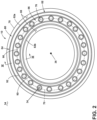
- FIG. 2 depicts a cross-section view of the combustion section 14 taken along line II-II of FIG. 1 .
- the combustion section 14 includes a combustor 80 having a set of fuel cups 76 disposed around a combustor centerline 36.
- the combustor centerline 36 can be in-line with, offset from, parallel to, or non-parallel to the engine centerline 21 of the gas turbine engine 10 ( FIG. 1 ).
- the combustor centerline 36 can be a centerline for an entirety of the combustion section 14, a single combustor, or a set of combustors that are arranged about the combustor centerline 36.
- the combustor 80 can have a can, can-annular, or annular arrangement depending on the type of engine in which the combustor 80 is located. In a non-limiting example, an annular arrangement is illustrated and disposed within a casing 78.
- the combustor 80 is defined by a liner 82 including an outer liner 82a and an inner liner 82b concentric with respect to each other and annular about the combustor centerline 36.
- the combustor 80 includes a dome assembly 84 including a dome wall 90.
- the combustion chamber 86 is annular about the combustor centerline 36.
- At least one fuel cup 76 illustrated as multiple fuel injectors annularly arranged about the combustor centerline 36, is fluidly coupled to the combustion chamber 86.
- a compressed air passageway 88 can be defined at least in part by both the liner 82 and the casing 78.
- the at least one fuel cup 76 is included within a plurality of fuel cups 76.
- Each fuel cup 76 can include a fuel cup centerline 34 that extends into the page.
- Each fuel cup centerline 34 can be arranged along a circumferential line 70.
- one or more fuel cups 76 can be offset from the circumferential line 70.
- the fuel cups 76 can be arranged such that the fuel cup centerlines 34 form a pattern relative to, but not necessarily on, the circumferential line 70.
- FIG. 3 depicts a cross-section view taken along line III-III of FIG. 2 illustrating the combustion section 14.
- the fuel cup 76 can be coupled to and disposed within the dome assembly 84.
- the fuel cup 76 can include a flare cone 104 and a swirler 112.
- the flare cone 104 includes an outlet 96 of the fuel cup 76 directly fluidly coupled to the combustion chamber 86.
- the fuel cup 76 is fluidly coupled to a fuel inlet 98 via a linear passageway 100.
- Both the outer and inner liners 82a, 82b have an outer surface 106 and an inner surface 108.
- the inner surface 108 at least partially defining the combustion chamber 86.
- the liner 82 can be made of one continuous monolithic portion or be multiple monolithic portions assembled together to define the outer and inner liners 82a, 82b.
- the outer surface 106 can define a first piece of the liner 82 while the inner surface 108 can define a second piece of the liner 82 that when assembled together form the liner 82.
- the liner 82 can be any type of liner 82, including but not limited to a single wall or a double walled liner or a tile liner.
- An ignitor 110 can be provided at the liner 82 and fluidly coupled to the combustion chamber 86, at any location.
- a mean centerline 124 When viewed from an axial plane extending from the combustor centerline 36 ( FIG. 2 ) and passing through a center point of the fuel cup 76, a mean centerline 124, lying in the axial plane, extends through the combustion chamber 86 equidistant between the inner liner 82b and the outer liner 82a.
- the mean centerline 124 can begin at or be radially offset from the fuel cup centerline 34 ( FIG. 2 ) at the outlet 96.
- the compressed air passageway 88 is formed between the outer surface 106 of the outer liner 82a and the inner liner 82b, and opposing portions of the casing 78.
- a first set of dilution passages 92 can extend through the dome wall 90 and exhaust to the combustion chamber 86.
- a second set of dilution passages 120 can extend through at least one of the inner liner 82b and the outer liner 82a.
- Each dilution passage of the second set of dilution passages 120 includes an inlet 126 provided on the outer surface 106 and a dilution hole 122 provided on the inner surface 108.
- the second set of dilution passages 120 fluidly couple the compressed air passageway 88 to the combustion chamber 86
- a set of baffles 130 is provided within a portion of the compressed air passageway 88 axially aligned with at least a portion of the second set of dilution passages 120.
- Each baffle of the set of baffles 130 are operably coupled to an arm 132.
- the arm 132 is operably coupled to an actuator 136.
- the actuator 136 can be any suitable device used to translate the arm in at least one direction.
- the actuator 136 can be an AC or DC motor, a DC motor, a pneumatic pump, an engine, a hydraulic pump, an electromagnetic actuator, a piezoelectric motor, or an electromechanical motor.
- the set of baffles 130 can include any number of one or more baffles. Further, while illustrated as being provided radially outward from both of the inner liner 82b and the outer liner 82a, with respect to the mean centerline 124, it will be appreciated that the set of baffles 130 can be provided radially outward from a single liner of the inner liner 82b or the outer liner 82a.
- a compressed airflow (C) can flow from the compressor section 12 ( FIG. 1 ) to the combustor 80 through the dome assembly 84.
- the compressed airflow (C) is fed to the fuel cup 76 via the swirler 112 as a swirler airflow (S).
- a flow of fuel (F) is fed to the fuel cup 76 via the fuel inlet 98 and the linear passageway 100.
- the swirler airflow (S) and the flow of fuel (F) are mixed at the flare cone 104 and fed to the combustion chamber 86 as a fuel/air mixture.
- the ignitor 110 can ignite the fuel/air mixture to define a flame within the combustion chamber 86, which generates a combustion gas (G). While shown as starting axially downstream of the outlet 96, it will be appreciated that the fuel/air mixture can be ignited at or near the outlet 96.
- the compressed airflow (C) is further fed to the first set of dilution passages 92 as a first dilution airflow (D1) and through the compressed air passageway 88 to the second set of dilution passages 120 as a second dilution airflow (D2).
- the first dilution airflow (D1) is used to direct and shape a flame
- the second dilution airflow (D2) is used to further shape and direct the combustion gas (G) or the flame. It is contemplated that the compressed airflow (C) fed through the second set of dilution passages 120 can make up greater than or equal to 20% and less than or equal to 80% of the total compressed airflow (C) that is fed to the combustor 80.
- the compressed airflow (C) fed through the second set of dilution passages 120 can make up greater than or equal to 30% and less than or equal to 50% of the total compressed airflow (C) that is fed to the combustor 80.
- At least a portion of the compressed airflow (C) in the compressed air passageway 88 can continue past the second set of dilution passages 120 and to downstream portions of the gas turbine engine 10 ( FIG. 1 ) to define a bypass compressed airflow (Cb).
- the bypass compressed airflow (Cb) can be used for any suitable purpose such as, but not limited to, cooling.
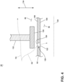
- FIG. 4 is a schematic side cross-sectional view of the baffle 130 taken along line IV-IV of FIG. 3 .
- the baffle 130 as described herein, is provided within the compressed air passageway 88 confronting the liner 82.
- the liner 82 can be any one of the outer liner 82a ( FIG. 3 ) or the inner liner 82b ( FIG. 3 ).
- the second set of dilution passages 120 will hereinafter be referred to as the set of dilution passages 120.
- the baffle 130 axially overlies at least a portion of the dilution passage 120.
- the baffle 130 axially overlies the inlet 126 of the dilution passage 120.
- the baffle 130 is movable, via the arm 132.
- the baffle 130 has a range of movement that has a degree of freedom in at least one of the radial direction or an axial direction.
- the degree of freedom of the baffle 130 is along a radial plane of movement 134.
- the baffle 130 is in a first position where the second dilution airflow (D2) is free to flow into the dilution passage 120 through the inlet 126.
- the baffle 130 can be moved along the radial plane of movement 134 a maximum radial distance from the outer surface 106 of the liner 82.
- the maximum radial distance can be an instance where the baffle 130 confronts and contacts a respective portion of the casing 78 ( FIG. 3 ).
- the baffle 130 can further be sized such that it sits flush against a respective portion the liner 82 or the casing 78.
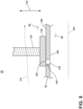
- FIG. 5 is a schematic side cross-sectional view of the baffle 130 of FIG. 3 in a second position.
- the baffle 130 as illustrated, is in the second position where the second dilution airflow (D2) is impeded or otherwise stopped from flowing into the dilution passage 120.
- the baffle 130 is moveable between the first position ( FIG. 4 ) and the second position to effectively occlude the compressed airflow (C) from the inlet 126 of the dilution passage 120. It will be appreciated that in the first position, the compressed airflow (C) is fully occluded and when the baffle 130 is in the second position, the compressed airflow
- (C) can be less than 100% and greater than or equal to 0% occluded.
- the baffle 130 When the baffle 130 partially or fully occludes the compressed airflow (C) from the dilution passage 120, the compressed airflow (C) that would flow into the dilution passage 120 if the dilution passage 120 were not occluded can instead flow to a downstream portion of the gas turbine engine ( FIG. 1 ) as the bypass compressed airflow (Cb).
- the positioning of the baffle 130 can be used to tailor the amount of the second dilution airflow (D2) and the bypass compressed airflow (Cb) that flows through the combustor 80 ( FIG. 3 ).
- the positioning of the baffle 130 can further be used to tailor at least one flow characteristic of the second dilution airflow (D2).
- the baffle 130 can be positioned with respect to the inlet 126 such that the baffle 130 acts as a nozzle for the second dilution airflow (D2) being fed to the inlet 126.
- the baffle 130 can accelerate and pressurize the second dilution airflow (D2).
- the control of the amount and the flow characteristics of the second dilution airflow (D2) flowing through the dilution passage 120 by the baffle 130 can be used for flame-shaping purposes.
- an ignited mixture of fuel (F) and the first dilution airflow (D1) can generate a flame or otherwise the combustion gases (G).
- the second dilution airflow (D2) is used to affect how the flame or the combustion gases flow through the combustion chamber 86.
- a faster and larger volume of the second dilution airflow (D2) can be used to penetrate into the combustion chamber 86 and effectively reduce the footprint of the flame or the combustion gases (G) within the combustion chamber 86.
- the baffle 130 is moved to close off the inlet 126 such that no second dilution airflow (D2) flows into the combustion chamber 86, the flame or the combustion gases (G) will have more room to expand and thus have a larger footprint.
- the shaping of the flame or the combustion gases (G) is hereinafter referred to as flame shaping. It is contemplated that flame shaping through the presence or non-presence of the second dilution airflow (D2) by the selective movement of the baffle 130 can be used to tailor the footprint or profile of the flame within the combustion chamber 86.
- the flame shaping can further be used to tailor a temperature distribution at the outlet of the combustion chamber 86. As a non-limiting example, a uniform temperature distribution at the outlet can ensure that the gas turbine engine 10 is uniformly thermally loaded downstream of the combustion section 14, thus increasing the efficiency and lifespan of the gas turbine engine 10 ( FIG. 1 ).
- the positioning of the baffle 130 can further be dependent on the operational state of the gas turbine engine 10 ( FIG. 1 ). For example, it has been found that during a relight condition (e.g., during initial ignition or restart ignition of the fuel/air mixture exiting the fuel cup 76 of FIG. 3 ), the baffle 130 can fully or partially cover the set of dilution passages 120 such that a maximum amount of compressed air (C) ( FIG. 3 ) flows into the combustion chamber 86 as the first dilution airflow (D1), into the swirler 112 as the swirler airflow (S) or otherwise to a downstream portion of the gas turbine engine 10 as the bypass compressed airflow (Cb).
- C compressed air
- maximizing, for example, the swirler airflow (S) and the first dilution airflow (D1) can help with initial flame propagation and shaping to ensure proper ignition of the gas turbine engine 10. Further, maximizing the amount of compressed air (C) being fed to the swirler 112 by closing the baffle 130, increases the flow through the swirler 112 which increases the pressure drop across the swirler 112 and a velocity of the flow exiting the swirler 112 at the outlet 96. Once ignited, it may be desirable to have further flame shaping through use of the set of dilution passages 120. As such, the baffle 130 can be moved to partially uncover or fully uncover the inlets 126, thus allowing the second dilution airflow (D2) to flow into the combustion chamber 86.
- the combustor 80 shown of FIG. 3 is well suited for the use of a hydrogen-containing gas as the fuel because it helps contain the faster moving flame front associated with hydrogen fuel, as compared to traditional hydrocarbon fuels. However, the combustor 80 can be used with traditional hydrocarbon fuels.
- the baffle 130 is especially advantageous in instances where the fuel used in the combustion section 14 is a hydrogen-containing fuel.
- Hydrogen-containing fuel has a higher calorific value than conventional fuels (e.g., fuels using carbons), thus the flame or combustion gases (G) generated with hydrogen-containing fuels is hotter than a flame or combustion gases that are generated with conventional fuels.
- directing the flame away from various portions of the combustion section 14 e.g., the inner liner 82b and the outer liner 82a
- D2 second dilution airflow
- the flame generated by the hydrogen-containing fuel has a higher velocity than a flame generated by a conventional fuel.
- the higher velocity in turn, means that the flame tends to want to keep its shape, which can result in a non-uniform flame and temperature distribution at the outlet of the combustor 80.
- the baffle 130 is used to ensure that the flames or combustion gases (G) have a uniform temperature and flame distribution at the outlet of the combustion chamber 86.
- increasing the velocity of the flow exiting the outlet 96 of the fuel cup 76 is especially advantageous when using hydrogen as a fuel. It has been found that the increase in the velocity of the hydrogen fuel and air mixture at the outlet 96, in turn, reduces chances of flashback and flame holding on the fuel cup 76 and the dome wall 90.
- FIG. 6 is a schematic transverse cross-sectional view of the combustor 80 taken along line VI-VI of FIG. 3 .
- the set of baffles 130 can extend circumferentially continuously about or be circumferentially segmented about the mean centerline 124 ( FIG. 3 ) or the combustor centerline 36.
- the set of baffles 130 can include two or more circumferentially adjacent baffles 130. Each baffle of the two or more circumferentially adjacent baffles 130 can be independently movable via a respective arm 132 and further overlay a respective portion of the set of dilution passages 120. Each arm 132 can be coupled to a respective actuator 136 ( FIG. 3 ) or to a single common actuator 136.
- Each baffle of the two or more circumferentially adjacent baffles 130 can further correspond to any number of one or more fuel cups 76.
- each baffle of the two or more circumferentially adjacent baffles 130 can extend circumferentially across two respective fuel cups 76.
- the independent movement of the baffles of the two or more circumferentially adjacent baffles 130 allows for further flame shaping by controlling the location where the second dilution airflow (D2) ( FIG. 3 ) flows into the combustion chamber 86.
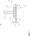
- FIG. 7 is a schematic side cross-sectional view of an exemplary baffle 230 provided within a combustor 280 suitable for use within the combustor 80 of FIG. 3 .
- the combustor 280 is similar to the combustor 80, therefore, like parts will be identified by like numerals increased to the 200 series with it being understood that the description of the combustor 80 applies to the combustor 280 unless noted otherwise.
- the combustor 280 includes a liner 282 with an outer surface 206 and an inner surface 208.
- a dilution passage 220 extends through the liner 282 between an inlet 226 provided on the outer surface 206 and a dilution hole 222 provided on the inner surface 208.
- the inner surface 208 confronts and at least partially defines a combustion chamber 286.
- a mean centerline 224 extends through the combustion chamber 286.
- the outer surface 206 at least partially defines a compressed air passageway 288.
- the baffle 230 is provided within a portion of the compressed air passageway 288. The baffle 230 is movable within the compressed air passageway 288 via an arm 232.
- the baffle 230 is similar to the baffle 130 ( FIG. 3 ), as the baffle 230 occludes the second dilution airflow (D2) ( FIG. 3 ) from the inlet 226 of the dilution passage 220.
- the baffle 230 has a range of movement that has a degree of freedom in at least one of the radial direction or an axial direction.
- the degree of freedom of the baffle 130 is along an axial plane of movement 238 rather than the radial plane of movement 134 ( FIG. 4 ). It is contemplated that the baffle 230, therefore, can be slidably moved over the inlet 226 to fully cover, partially cover, or fully uncover the inlet 226. In the instance where the inlet 226 is partially covered, the baffle 230 acts as a nozzle for the compressed airflow (C) ( FIG. 3 ) flowing into the inlet 226.
- the set of dilution passages 220 can include any number of one or more axially downstream dilution passages 240.
- the baffle 230 can be sized to partially cover, fully cover, or fully uncover the one or more axially downstream dilution passages 240.
- the baffle 230 is movable such that the axially downstream dilution passages 240 and the axially upstream dilution passages have varying degrees of occlusion. It will be appreciated that the baffle 230 can be sized such that the baffle 230 can simultaneously fully cover, partially cover, or fully uncover all dilution passages of the set of dilution passages 220 including the one or more axially downstream dilution passages 240.
- the selective occlusion of the compressed airflow to the set of dilution passages 220 optionally including the axially downstream dilution passage 240 can be used to further tailor the flame shaping.
- fully uncovering or partially uncovering the axially downstream dilution passages 240 can be used to further shape the flame or combustion gases (G) downstream of the axially forward dilution passages of the set of dilution passages 220.
- blocking the upstream dilution passages 220 and allowing the second dilution airflow (D2) to flow through the axially downstream dilution passage 240 can allow for the flame or combustion gases (G) to further expand radially outward from the mean centerline 224, hereinafter referred to as an increase in flame volume.
- the increase in flame volume in turn, achieves better flame stability.
- opening the axially downstream dilution passages 240, during relight, can allow for a more stable flame and thus increase the efficiency of the combustor 280 during startup of the combustor 280.
- varying the occlusion of the set of dilution passages 220 and the set of axially downstream dilution passages 240 can further limit the amount of emissions generated by the combustion process.
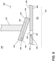
- FIG. 8 is a schematic side cross-sectional view of an exemplary baffle 330 provided within a combustor 380 suitable for use within the combustor 80 of FIG. 3 .
- the combustor 380 is similar to the combustor 80, 280, therefore, like parts will be identified by like numerals increased to the 300 series with it being understood that the description of the combustor 80, 280 applies to the combustor 380 unless noted otherwise.
- the combustor 380 includes a liner 382 with an outer surface 306 and an inner surface 308.
- a dilution passage 320 extends through the liner 382 between an inlet 326 provided on the outer surface 306 and a dilution hole 322 provided on the inner surface 308.
- the inner surface 308 confronts and at least partially defines a combustion chamber 386.
- a mean centerline 324 extends through the combustion chamber 386.
- the outer surface 306 at least partially defines a compressed air passageway 388.
- the baffle 330 is provided within a portion of the compressed air passageway 388.
- the baffle 330 is movable within the compressed air passageway 388 via an arm 332.
- the baffle 330 has a range of movement that has a degree of freedom in at least one of the radial direction or an axial direction.
- the baffle 330 is similar to the baffle 130, 230 as the baffle 330 occludes the second dilution airflow (D2) ( FIG. 3 ) from the inlet 326 of the dilution passage 320.
- the baffle 330 includes a major body axis 350 extending at a radial baffle angle 346 with respect to a projection 348 of the mean centerline 324.
- the baffle 330 is radially inclined with respect to the mean centerline 324.
- the radial baffle angle 346 can be any suitable size.
- the radial baffle angle 346 can have an absolute value of greater than or equal to 0 degrees and less than or equal to 80 degrees.
- the inclination of the baffle 330 is used to funnel the compressed airflow (C) into the inlet 326.
- the inclination of the baffle 330 can further be used as a nozzle to accelerate and pressurize the compressed airflow (C) prior to it entering the inlet 326.
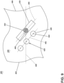
- FIG. 9 is a schematic top-down view of an exemplary baffle 430 provided within a combustor 480 suitable for use within the combustor 80 of FIG. 4 .
- the combustor 480 is similar to the combustor 80, 280, 380, therefore, like parts will be identified by like numerals increased to the 400 series with it being understood that the description of the combustor 80, 280, 380 applies to the combustor 480 unless noted otherwise.
- the combustor 480 includes a liner 482 with an outer surface 406.
- a dilution passage 420 extends through the liner 482 from an inlet 426 provided on the outer surface 406.
- the liner 482 confronts and at least partially defines a combustion chamber (not illustrated, e.g., the combustion chamber 86 of FIG. 3 ).
- a mean centerline, illustrated as a projection 448, extends through the combustion chamber.
- the outer surface 406 at least partially defines a compressed air passageway 488.
- the baffle 430 is provided within a portion of the compressed air passageway 488.
- the baffle 430 is movable within the compressed air passageway 488 via an arm 432.
- the baffle 430 has a range of movement that has a degree of freedom in at least one of the radial direction or an axial direction.
- the baffle 430 is similar to the baffle 130, 230, 330 in that the baffle 430 occludes a compressed airflow (e.g., the compressed airflow (C) of FIG. 3 ) from the inlet 426.
- the baffle 430 includes a major body axis 450 forming a circumferential baffle angle 460 with respect to the projection 448 of the mean centerline.
- the circumferential baffle angle 460 can be any suitable angle.
- the circumferential baffle angle 460 can have an absolute value of greater than or equal to 0 degrees and less than or equal to 90 degrees.
- the circumferential baffle angle can have an absolute value of less than 90 degrees.
- the set of dilution passages 420 include a series of axially spaced dilutions passages.
- Each dilution passage of the set of dilution passages 420 includes a dilution passage centerline (e.g., the dilution passage centerline 34 of FIG. 2 ) that intersects the inlet 426 at a center point 444.
- the set of dilution passages 420 can be provided along a line 462 that extends between each consecutive center point 444 of the set of dilution passages 420.
- the major body axis 450 can correspond to or otherwise be parallel to the line 462.
- the baffle 430 can be moved to cover, partially uncover, or fully uncover all dilution passages of the set of dilution passages 420 at once.
- the line 462, and therefore the major body axis 450 can be linear or non-linear.
- the baffle 430 can be curved or non-curved.
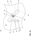
- FIG. 10 is a schematic top-down view of an exemplary baffle 530 provided within a combustor 580 suitable for use within the combustor 80 of FIG. 5 .
- the combustor 580 is similar to the combustor 80, 280, 380, 480, therefore, like parts will be identified by like numerals increased to the 500 series with it being understood that the description of the combustor 80, 280, 380, 480 applies to the combustor 580 unless noted otherwise.
- the combustor 580 includes a liner 582 with an outer surface 506.
- a dilution passage 520 extends through the liner 582 from an inlet 526 provided on the outer surface.
- the liner 582 confronts and at least partially defines a combustion chamber (not illustrated, e.g., the combustion chamber 86 of FIG. 3 ).
- a mean centerline, illustrated as a projection 548, extends through the combustion chamber.
- the outer surface 506 at least partially defines a compressed air passageway 588.
- the baffle 530 is provided within a portion of the compressed air passageway 588.
- the baffle 530 is movable within the compressed air passageway 588 via an arm 532.
- the baffle 530 has a range of movement that has a degree of freedom in at least one of the radial direction or an axial direction.
- the baffle 530 is similar to the baffle 430 in that it includes a major body axis 550 that forms a circumferential baffle angle 560 with respect to the projection 548.
- the difference, however, is that the set of dilution passages 520 are circumferentially spaced along a line 562 that is perpendicular to the projection 548, and extends through a center point 544 of each dilution passage 520.
- the major body axis 550 is non-parallel to the line 562. As such, the amount of occlusion is non-constant between circumferentially adjacent dilution passages when the baffle 530 is moved over a respective dilution passage 520.
- the baffle 530 can further be movable, via the arm 532, about a rotational axis (Rax).
- the size of the circumferential baffle angle 560 can be varied by rotating the baffle 530 about the rotational axis (Rax).
- the baffle 530 can be used to selectively fully occlude, partially occlude or not occlude (e.g., fully open) at least one of the dilution passages of the set of dilution passages 520 that are in a circumferential row.
- the baffle 530 can fully occlude a first dilution passage while leaving a second dilution passage, circumferentially adjacent the first dilution passage not occluded or partially occluded. It is contemplated that providing differing amounts of occlusion along the set of dilution passages 520 arranged in the circumferential row can allow for increased temperature control of the flame or combustion gases (G) within the combustion chamber.
- the baffle 530 can be moved to direct compressed air through the second dilution passage to effectively push away from the liner 582 or otherwise cool the hot portions of the flame.
- the cooling of the hotter regions of the flame results in a uniform temperature distribution at the outlet of the combustor 580. This ultimately reduces the emissions and achieves a better flame profile at the outlet of the combustor 580.
- the circumferential baffle angle 560 can be varied to change the degree of occlusion of each dilution passage of the set of dilution passages 520.
- the arm 532 can move the baffle 530 such that the major body axis 550 is parallel to the line 562.
- FIG. 11 is a schematic side cross-sectional view of an exemplary baffle 630 provided within a combustor 680 suitable for use within the combustor 80 of FIG. 3 .
- the combustor 680 is similar to the combustor 80, 280, 380, 480, 580, therefore, like parts will be identified by like numerals increased to the 600 series with it being understood that the description of the combustor 80, 280, 380, 480, 580 applies to the combustor 680 unless noted otherwise.
- the combustor 680 includes a casing 678 and a liner 682 with an outer surface 606 and an inner surface 608.
- a dilution passage 620 extends through the liner 682 between an inlet 626 provided on the outer surface 606 and a dilution hole 622 provided on the inner surface 608.
- the inner surface 608 confronts and at least partially defines a combustion chamber 686.
- a mean centerline 624 extends through the combustion chamber 686.
- the outer surface 606 at least partially defines a compressed air passageway 688.
- the baffle 630 is provided within a portion of the compressed air passageway 688. The baffle 630 is movable within the compressed air passageway 688 via an arm 632.
- the combustor 680 is similar to the combustor 80, 280, 380, 480, 580 in that it includes the compressed air passageway 688 at least partially defined within a radial space between the outer surface 606 and the casing 678.
- the compressed air passageway 688 includes a first channel 656 and a second channel 658 split by a wall 654 extending through the compressed air passageway 688.
- the wall 654 can start along any suitable axial location of the compressed air passageway 688 that is at least upstream of an axially forwardmost inlet 626 of the set of dilution passages 620. It is further contemplated that the wall 654 can join with the liner 682 downstream of the set of dilution passages 620 or that the first channel 656 and the second channel 658 can merge downstream of the set of dilution passages 620.
- the inlet 626 can be fluidly coupled to the first channel 656 while the second channel 658 can be fluidly coupled to any suitable downstream portion of the gas turbine engine 10 ( FIG. 1 ).
- a static arm 652 can operably couple to baffle 630 to the casing 678.
- the baffle 630 is statically mounted to the static arm 652 and slidably coupled to the arm 632. As such, when the arm 632 is moved, the baffle 630 rotates about the static arm 652 to allow for the selective occlusion of the compressed air flow into the first channel 656.
- the baffle 630 is in a first position where the first channel 656 and the second channel 658 are each open.
- the compressed airflow (C) ( FIG. 3 ) can flow into the first channel 656 and thus the inlet 626 as the second dilution airflow (D2) and into the second channel 658 as the bypass compressed airflow (Cb).
- the baffle 630 can at least partially occlude the compressed airflow (C) to the inlet 626.
- the baffle 630 can act as a nozzle.
- first channel 656 and the second channel 658 can be switched such that the first channel 656 is the second channel 658 and vice-versa.
- a dilution channel 668 illustrated in phantom lines
- the dilution channel 668 is defined as a portion of the dilution passage 620 and the inlet 626 is provided on a portion of the wall 654 confronting the first channel 656.
- the dilution channel 668 can extend through a portion of the second channel 658.
- the baffle 630 is used to occlude the compressed airflow (C) from the second channel 658 rather than the first channel 656.
- FIG. 12 is a schematic side cross-sectional view of the baffle 630 of FIG. 11 .
- the baffle 630 is in a second position where the first channel 656 and thus the inlet 626 is fully occluded from the compressed airflow (C) ( FIG. 3 ).
- the compressed airflow (C) flows entirely through the second channel 658 as the bypass compressed airflow (Cb).
- FIG. 13 is a schematic side cross-sectional view of an exemplary baffle 730 provided within a combustor 780 suitable for use within the combustor 80 of FIG. 3 .
- the combustor 780 is similar to the combustor 80, 280, 380, 480, 580, 680, therefore, like parts will be identified by like numerals increased to the 700 series with it being understood that the description of the combustor 80, 280, 380, 480, 580, 680 applies to the combustor 780 unless noted otherwise.
- the combustor 780 includes a casing 778 and a liner 782 with an outer surface 706 and an inner surface 708.
- a dilution passage 720 extends through the liner 782 between an inlet 726 provided on the outer surface 706 and a dilution hole 722 provided on the inner surface 708.
- the inner surface 708 confronts and at least partially defines a combustion chamber 786.
- a mean centerline 724 extends through the combustion chamber 786.
- the outer surface 706 at least partially defines a compressed air passageway 788.
- the baffle 730 is provided within a portion of the compressed air passageway 788. The baffle 730 is movable within the compressed air passageway 788 via an arm 732.
- the combustor 780 is similar to combustor 680 in that it includes the compressed air passageway 788 including a first channel 756 and a second channel 758 split by a wall 754 extending through the compressed air passageway 788.
- the baffle 730 is pivotable about a static arm 752 to fully uncover, partially cover, or fully cover both of the first channel 756 and the second channel 758.
- the baffle 730 is movable to fully cover or partially cover the first channel 756, leaving the second channel 758 fully uncovered and vice-versa.
- the baffle 730 allows for the selective fluid coupling of the compressed airflow (C) ( FIG. 3 ) to one of or both of the first channel 756 and the second channel 758.
- the baffle 730 has a range of movement in both the radial direction and the axial direction.
- FIG. 14 is a schematic side cross-sectional view an exemplary set of baffles 830 provided within a combustor 880 suitable for use within the combustor 80 of FIG. 3 .
- the combustor 880 is similar to the combustor 80, 280, 380, 480, 580, 680, 780, therefore, like parts will be identified by like numerals increased to the 800 series with it being understood that the description of the combustor 80, 280, 380, 480, 580, 680, 780 applies to the combustor 880 unless noted otherwise.
- the combustor 880 includes a casing 878, an outer liner 882a and an inner liner 882b each with an outer surface 806 and an inner surface 808.
- a dilution passage 820 extends through the outer and inner liners 882a, 882b between an inlet 826 provided on the outer surface 806 and a dilution hole 822 provided on the inner surface 808.
- the inner surface 808 confronts and at least partially defines a combustion chamber 886.
- a mean centerline 824 extends through the combustion chamber 886.
- the outer surface 806 at least partially defines a compressed air passageway 888.
- the set of baffles 830 are provided within respective portions of the compressed air passageway 888. Each baffle 830 of the set of baffles 830 is movable within the compressed air passageway 888 via an arm 832.
- the combustor 880 is similar to the combustor 680, 780 in that the compressed air passageway 888 is split into a first channel 856 and a second channel 858 via a wall 854.
- the combustor 880 further includes at least two baffles 830; one baffle provided in a portion of the compressed air passageway 888 confronting the outer liner 882a and another baffle provided in a portion of the compressed air passageway 888 confronting the inner liner 882b.
- the first channel 856 can be provided radially outward from or radially inward from the second channel 858, with respect to the mean centerline 824.
- the set of baffles 830 are operably coupled to a respective static arm 852. As illustrated, at least two baffles of the set of baffles 830 are operably coupled to a single static arm 852 and pivotable about the single static arm 852 via the movement of a single arm 832.
- the baffle 830 has a range of movement in both the radial direction and the axial direction.
- the static arm 852 can extend from opposing portions of a casing 878 or otherwise extend from one portion of the casing 878 and be directly coupled to a radially farthest baffle of the set of baffles 830. In either case, the static arm 852 can extend through or around the combustion chamber 886. Alternatively, the static arm 852 can be provided axially forward of the combustion chamber 886 and extend through a portion of the compressed air passageway 888.
- the at least two baffles of the set of baffles 830 are coupled to the same arm 832, the at least two baffles of the set of baffles 830 are dependently movable with respect to one another.
- At least a portion of the combustor 880 can be non-symmetric about the mean centerline 824.
- the first channel 856 and the second channel 858 radially nearest the outer liner 882a can be non-symmetric with respect to the first channel 856 and the second channel 858 provided radially nearest the inner liner 882b.
- one of the first channel 856 would be radially outward from the second channel 858 such that a dilution channel 868 can be provided to interconnect the first channel 856 with a remainder of the dilution passage 820.
- the baffles 830 are non-symmetric about the mean centerline 824.
- the baffles 830, the first channel 856, and the second channel 858 can be symmetric about the mean centerline 824.
- the benefit of utilizing the illustrated configuration where at least two baffles 830 are controlled by a single arm 832 is that the number of needed actuators (e.g., the actuator 136 of FIG. 3 ) is reduced. In other words, a single actuator can be used to move two or more baffles 830.
- FIG. 15 is a schematic side cross-sectional view an exemplary set of baffles 930 provided within a combustor 980 suitable for use within the combustor 80 of FIG. 3 .
- the combustor 980 is similar to the combustor 80, 280, 380, 480, 580, 680, 780, 880, therefore, like parts will be identified by like numerals increased to the 900 series with it being understood that the description of the combustor 80, 280, 380, 480, 580, 680, 780, 880 applies to the combustor 980 unless noted otherwise.
- the combustor 980 includes a casing 978 an outer liner 982a and an inner liner 982b each with an outer surface 906 and an inner surface 908.
- a dilution passage 920 extends through the outer and inner liners 982a, 982b between an inlet 926 provided on the outer surface 906 and a dilution hole 922 provided on the inner surface 908.
- the inner surface 908 confronts and at least partially defines a combustion chamber 986.
- a mean centerline 924 extends through the combustion chamber 986.
- the outer surface 906 at least partially defines a compressed air passageway 988.
- the set of baffles 930 are provided within respective portions of the compressed air passageway 988. Each baffle 930 of the set of baffles 930 is movable within the compressed air passageway 988 via an arm 932.
- the combustor 980 is similar to the combustor 680, 780, 880 in that the compressed air passageway 988 is split into a first channel 956 and a second channel 958 via a wall 954.
- the combustor 980 is similar to the combustor 880 in that it includes a single static arm 952 operably coupling two or more baffles 930 to the casing 978.
- the combustor 980 includes two independently movable baffles 930 coupled to the same static arm 952.
- each baffle 930 includes a respective arm 932 coupled to a respective actuator (not illustrated, e.g., actuator 136 of FIG. 3 ).
- the set of baffles 930, the arms 932, the static arm 952, the first channel 956 and the second channel 958 can by symmetric about the mean centerline 924.
- FIG. 16 is a schematic side cross-sectional view an exemplary set of baffles 1030 provided within a combustor 1080 suitable for use within the combustor 80 of FIG. 3 .
- the combustor 1080 is similar to the combustor 80, 280, 380, 480, 580, 680, 780, 880, 980, therefore, like parts will be identified by like numerals increased to the 1000 series with it being understood that the description of the combustor 80, 280, 380, 480, 580, 680, 780, 880, 980 applies to the combustor 1080 unless noted otherwise.
- the combustor 1080 includes a casing 1078, an outer liner 1082a and an inner liner 1082b.
- the combustor 1080 is defined by a combustor centerline 1070.
- a dilution passage 1020 extends through the outer and inner liners 1082a, 1082b between an inlet 1026 and a dilution hole 1022.
- the inner liner 1082b and the outer liner 1082a at least partially define a combustion chamber 1086.
- a mean centerline 1024 extends through the combustion chamber 1086.
- a compressed air passageway 1088 extends around the inner liner 1082b and the outer liner 1082a.
- the set of baffles 1030 are provided within respective portions of the compressed air passageway 1088. Each baffle 1030 of the set of baffles 1030 is movable within the compressed air passageway 1088 via an arm 1032 coupled to an actuator 1036.
- the combustor 1080 is similar to the combustor 80, 280, 380, 480, 580, 680, 780, 880, 980 in that it includes a fuel cup 1076 that exhausts a flame or fuel/air mixture into the combustion chamber 1086.
- the combustor 1080 includes the mean centerline 1024 that turns upwardly (e.g.., radially) away from the combustor centerline 1070.
- Each baffle of the set of baffles 1030 can be radially or axially moveable with respect to the mean centerline 1024. It will be appreciated that the set of baffles 1030 can be provide along a portion of the combustor 1080 where the mean centerline 1024 is non-parallel to the combustor centerline 1070. When radially movable with respect to the mean centerline 1024, each radially movable baffle of the set of baffles 1030 is axially movable with respect to the combustor centerline 1070. When axially movable with respect to the mean centerline 1024, each axially movable baffle of the set of baffles 1030 is radially movable with respect to the combustor centerline 1070.
- baffles 130, 230, 330, 430, 530, 630, 730, 830, 930, 1030 can be applied to any suitable combustor.
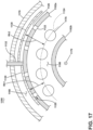
- FIG. 17 is a schematic transverse cross-sectional view of an exemplary combustor 1180 suitable for use as the combustor 80 of FIG. 3 .
- the combustor 1180 is similar to the combustor 80, 280, 380, 480, 580, 680, 780, 880, 980, therefore, like parts will be identified by like numerals increased to the 1100 series with it being understood that the description of the combustor 80, 280, 380, 480, 580, 680, 780, 880, 980 applies to the combustor 1180 unless noted otherwise.
- the combustor 1180 includes a casing 1178, an outer liner 1182a and an inner liner 1182b.
- the combustor 1180 is defined by a combustor centerline 1170.
- a dilution passage 1120 extends through the outer and inner liners 1182a between an inlet 1126 and a dilution hole 1122.
- the inner liner 1182b and the outer liner 1182a at least partially define a combustion chamber 1186.
- a mean centerline 1124 extends through the combustion chamber 1186.
- a compressed air passageway 1188 extends around the inner liner 1182b and the outer liner 1182a.
- a set of fuel cups 1176 exhaust into the combustion chamber 1186.
- a set of baffles 1130 are provided within the compressed air passageway 1188 to occlude a flow of compressed air (C) ( FIG. 3 ) from a respective portion of the set of dilution passages 1120.
- the set of baffles 1130 include at least two circumferentially opposing baffles that are coupled to a single arm 1132 at circumferentially opposing ends of the single arm 1132.
- the opposing baffles of the set of baffles 1130 can be provided at a first radial height (Rh1) and a second radial height (Rh2), respectively, from the mean centerline 1124.
- the first radial height (Rh1) can be smaller than the second radial height (Rh2) such that when a portion of the dilution passages of the set of dilution passages are fully covered by the baffle at the first radial height (Rh1), another portion of the dilution passages of the set of dilution passages 1120 are partially covered or fully uncovered by the baffle at the second radial height (Rh2).
- the first radial height (Rh1) and the second radial height (Rh2) can be equal.
- the set of baffles 1130 have a range of movement that has a degree of freedom in at least one of the radial direction or an axial direction.
- Benefits of the present disclosure include a combustor suitable for use with a hydrogen-containing fuel.
- hydrogen-containing fuels have a higher flame temperature and velocity than traditional fuels (e.g., fuels not containing hydrogen). That is, hydrogen or a hydrogen mixed fuel typically has a wider flammable range and a faster burning velocity than traditional fuels such petroleum-based fuels, or petroleum and synthetic fuel blends.
- These high burn temperatures of hydrogen-containing fuel mean that additional insulation is needed between the ignited hydrogen-containing fuel and surrounding components of the gas turbine engine (e.g., the inner/outer liner, and other parts of the gas turbine engine).
- the combustor includes the baffle that can fully or at least partially occlude the second dilution airflow to the combustion chamber.
- This is used for flame shaping purposes, as described herein.
- the control of the second dilution airflow can direct the flame away from the liner, thus ensuring the liner is not overly heated.
- the baffle is used to create a uniform flame temperature within the combustion chamber. The shaping can further ensure that the combustion section or otherwise hot sections of the turbine engine do not fail or otherwise become ineffective by being overly heated, thus increasing the lifespan of the turbine engine.
- Benefits associated with using hydrogen-containing fuel over conventional fuels include an eco-friendlier engine as the hydrogen-containing fuel, when combusted, generates less carbon pollutants than a combustor using conventional fuels.
- a combustor including 100% hydrogen-containing fuel e.g., the fuel is 100% H 2
- the combustor, as described herein, can be used in instances where 100% hydrogen-containing fuel is used.
- a gas turbine engine that can utilize less fuel due to higher heating value of fuel to achieve same turbine inlet temperatures.
- a conventional gas turbine engine using conventional fuels will require more fuel to produce the same amount of work or engine output as the present gas turbine engine using hydrogen-containing fuels. This, in turn, means that either less amount of fuel can be used to generate the same amount of engine output as a conventional gas turbine engine, or the same amount of fuel can be used to generate an increased engine output when compared to the conventional gas turbine engine.
- a combustor for a gas turbine engine comprising a casing, an inner liner and an outer liner, a compressed air passageway formed between the casing, the inner liner and the outer liner, a combustion chamber at least partially defined by the inner liner and the outer liner, the combustion chamber having a mean centerline extending through the combustion chamber, the mean centerline being equidistant between the inner liner and the outer liner, at least one dilution passage extending through at least one of the inner liner and the outer liner, the at least one dilution passage extending between an inlet fluidly coupled to the compressed air passageway and a dilution hole fluidly coupled to the combustion chamber, and a baffle provided within the compressed air passageway, the baffle having a range of movement between a first position and a second position relative to the inlet of the at least one dilution passage to control a degree of occlusion of compressed airflow to the inlet.
- a combustor for a gas turbine engine comprising a casing, an inner liner and an outer liner, a compressed air passageway formed between the casing, the inner liner and the outer liner, with at least a portion of the compressed air passageway being split, via a wall, between a first channel and a second channel, a combustion chamber at least partially defined by the inner liner and the outer liner, the combustion chamber having a mean centerline extending through the combustion chamber, the mean centerline being equidistant between the inner liner and the outer liner, at least one dilution passage fluidly extending through at least one of the inner liner and the outer liner, the at least one dilution passage extending between an inlet directly fluidly coupled to the first channel and a dilution hole directly fluidly coupled to the combustion chamber, and a first arm, a second arm statically coupled to a portion of the casing, and a first baffle extending between the first arm and the second arm, the first baffle provided
- a method of fluidly coupling a flow of compressed air to a combustion chamber of a combustor comprising selectively occluding the flow of compressed air to at least one dilution passage through selective movement of a baffle along a degree of freedom.
- the at least one dilution passage includes at least one axially downstream dilution passage that is axially downstream an axially upstream dilution passage, with the baffle being movable such that the axially downstream dilution passage and the axially upstream dilution passage have varying degrees of occlusion.
- baffle includes a major body axis oriented at a radial baffle angle with respect to the mean centerline.
- baffle includes a circumferential baffle angle when viewed along a circumferential plane intersecting the baffle, with the circumferential baffle angle has an absolute value of less than 90 degrees.
- baffle includes a pair of opposing baffles and wherein the pair of opposing baffles extend from opposing circumferential sides of the arm.
- combustor of any preceding clause further comprising, a first fuel cup extending through a dome wall at least partially defining the combustion chamber, and a second fuel cup extending through the dome wall and being circumferentially spaced from the first fuel cup, with respect to the mean centerline, wherein a first baffle of the pair of opposing baffles extends circumferentially across the first fuel cup and a second baffle of the pair of opposing baffles extends circumferentially across the second fuel cup.
- the at least one dilution passage is included within a plurality of dilution passages provided on both the inner liner and the outer liner, with the dilution passages of the plurality of dilution passages provided on the inner liner and the dilution passages of the plurality of dilution passages provided on the outer liner being occluded by separate baffles.
- combustor of any preceding clause, wherein the combustor is defined by a combustor centerline and the baffle is movable at least one of either axially or radially, with respect to the combustor centerline.
- the combustor of any preceding clause further comprising at least one fuel cup provided on a dome wall at least partially defining the combustion chamber, the at least one fuel cup receiving a flow of hydrogen containing fuel.
- combustor of any preceding clause further comprising a second baffle located within a portion of the compressed air passageway radially inward from the inner liner, the second baffle being pivotable about the second arm, via the first arm.
- baffle sits flush against an outer surface of one of the outer liner or the inner liner when viewed along a radial plane extending perpendicularly from the mean centerline and intersecting the baffle.
- baffle includes a major body axis.
- the baffle (130, 230, 330, 430, 530, 630, 730, 830, 930, 1030, 1130) includes a circumferential baffle angle (460, 560) when viewed along a plane extending circumferentially about the mean centerline (124, 224, 324, 624, 724, 824, 924, 1024, 1124) and intersecting the baffle (130, 230, 330, 430, 530, 630, 730, 830, 930, 1030, 1130), with the circumferential baffle angle (460, 560) being variable during operation of the combustor (80, 280, 380, 480, 580, 680, 780, 880, 980, 1080, 1180).
Landscapes
- Engineering & Computer Science (AREA)
- Chemical & Material Sciences (AREA)
- Combustion & Propulsion (AREA)
- Mechanical Engineering (AREA)
- General Engineering & Computer Science (AREA)
Abstract
Description
- The present subject matter relates generally to a combustor, and more specifically to a combustor having a liner, and a dilution passage extending through the liner.
- Gas turbine engines are driven by a flow of combustion gases passing through the engine to rotate a multitude of turbine blades. A combustor can be provided within the gas turbine engine and is fluidly coupled with a turbine into which the combusted gases flow.
- Hydrocarbon fuels are commonly used in the combustor of a gas turbine engine. Generally, air and fuel are fed separately to the combustor, until they are mixed, and the mixture is combusted to produce hot combustion gas. The combustion gas is then fed to a turbine where it rotates the turbine to produce power. By-products of the hydrocarbon fuel combustion typically include nitrogen oxide and nitrogen dioxide (collectively called NOx), carbon monoxide (CO), unburned hydrocarbon (UHC) (e.g., methane and volatile organic compounds that contribute to the formation of atmospheric ozone), and other oxides, including oxides of sulfur (e.g., SO2 and SO3).
- A full and enabling disclosure of the present disclosure, including the best mode thereof, directed to one of ordinary skill in the art, is set forth in the specification, which makes reference to the appended figures, in which:
-
FIG. 1 is a schematic of a gas turbine engine. -
FIG. 2 is a schematic of a cross-section view taken along line II-II ofFIG. 1 of a combustion section of the gas turbine engine, the combustion section have a combustor centerline. -
FIG. 3 is a schematic of a side cross-sectional view taken along line III-III ofFIG. 2 of a combustor in the combustion section having a liner, a casing, a compressed air passageway formed between the liner and the casing, a dilution passage formed along the liner, and a baffle provided within the compressed air passageway and occluding a compressed airflow to the dilution passage. -
FIG. 4 is a schematic side cross-sectional view of the baffle taken along line IV-IV ofFIG. 3 , further illustrating the baffle in an open position. -
FIG. 5 is a schematic side cross-sectional of the baffle ofFIG. 3 , further illustrating the baffle in a closed position. -
FIG. 6 is a schematic transverse cross-sectional view of the combustor taken along line VI-VI ofFIG. 3 , further illustrating two baffles circumferentially extending across respective portions of the liner. -
FIG. 7 is a schematic side cross-sectional view of an exemplary baffle for a combustor suitable for use as the combustor ofFIG. 3 , the baffle being movable along the axial direction of a mean centerline of the combustor. -
FIG. 8 is a schematic side cross-sectional view of an exemplary baffle for a combustor suitable for use as the combustor ofFIG. 3 , the baffle being radially inclined at a radial baffle angle with respect to a mean centerline of the combustor. -
FIG. 9 is a schematic top-down view of an exemplary baffle for a combustor suitable for use as the combustor ofFIG. 3 , the baffle occluding the compressed airflow to a set of axially-spaced dilution passages and including a circumferential baffle angle with respect to a mean centerline of the combustor. -
FIG. 10 is a schematic top-down view of an exemplary baffle for a combustor suitable for use as the combustor ofFIG. 3 , the including a circumferential baffle angle with respect to a mean centerline of the combustor. -
FIG. 11 is a schematic side cross-sectional view of an exemplary baffle for a combustor suitable for use as the combustor ofFIG. 3 , the combustor including a first channel and a second channel, with the baffle being pivotable about a static arm to occlude the compressed airflow to the first channel, the baffle being in a first position. -
FIG. 12 is a schematic side cross-sectional view of the exemplary baffle ofFIG. 11 , the baffle being in a second position. -
FIG. 13 is a schematic side cross-sectional view of an exemplary baffle for a combustor suitable for use as the combustor ofFIG. 3 , the combustor including a first channel and a second channel, with the baffle being pivotable about a static arm to occlude the compressed airflow to the first channel or the second channel. -
FIG. 14 is a schematic side cross-sectional view of an exemplary set of baffles within a combustor suitable for as the combustor ofFIG. 3 , the two baffles being dependently movable. -
FIG. 15 is a schematic side cross-sectional view of an exemplary set of baffles within a combustor suitable for as the combustor ofFIG. 3 , the two baffles being independently movable. -
FIG. 16 is a schematic side cross-sectional view of an exemplary set of baffles within a combustor suitable for as the combustor ofFIG. 3 , the combustor including a mean centerline that is non-parallel to the combustor centerline. -
FIG. 17 is a schematic transverse cross-sectional view of an exemplary combustor suitable for use as the combustor ofFIG. 3 , further including two baffles provided at varying radial heights from a mean centerline of the combustor. - Aspects of the disclosure described herein are directed to a combustor. The combustor includes a combustion chamber at least partially defined by a dome wall, a casing, an inner liner and an outer liner. A compressed air passageway is formed between the casing, the inner liner and the outer liner. A set of dilution passages extend through at least one of the inner liner or the outer liner fluidly coupling the compressed air passageway to the combustion chamber. A baffle is provided in a portion of the compressed air passage. The baffle is movable to occlude a compressed air within the compressed air passageway to at least a portion of the set of dilution passages. As used herein, the term occlude is defined as to stop, limit, or otherwise constrict a flow of air from a first passage from entering a second passage.
- For purposes of illustration, the present disclosure will be described with respect to a gas turbine engine. It will be understood, however, that aspects of the disclosure described herein are not so limited and that a combustor as described herein can be implemented in engines, including but not limited to turbojet, turboprop, turboshaft, and turbofan engines. Aspects of the disclosure discussed herein may have general applicability within non-aircraft engines having a combustor, such as other mobile applications and non-mobile industrial, commercial, and residential applications.
- The word "exemplary" is used herein to mean "serving as an example, instance, or illustration." Any implementation described herein as "exemplary" is not necessarily to be construed as preferred or advantageous over other implementations. Additionally, unless specifically identified otherwise, all embodiments described herein should be considered exemplary.
- As used herein, the terms "first", "second", and "third" may be used interchangeably to distinguish one component from another and are not intended to signify location or importance of the individual components.
- The terms "forward" and "aft" refer to relative positions within a gas turbine engine or vehicle, and refer to the normal operational attitude of the gas turbine engine or vehicle. For example, with regard to a gas turbine engine, forward refers to a position closer to an engine inlet and aft refers to a position closer to an engine nozzle or exhaust.
- As used herein, the term "upstream" refers to a direction that is opposite the fluid flow direction, and the term "downstream" refers to a direction that is in the same direction as the fluid flow. The term "fore" or "forward" means in front of something and "aft" or "rearward" means behind something. For example, when used in terms of fluid flow, fore/forward can mean upstream and aft/rearward can mean downstream.
- The term "fluid" may be a gas or a liquid. The term "fluid communication" means that a fluid is capable of making the connection between the areas specified.
- Additionally, as used herein, the terms "radial" or "radially" refer to a direction away from a common center. For example, in the overall context of a gas turbine engine, radial refers to a direction along a ray extending between a center longitudinal axis of the engine and an outer engine circumference.
- All directional references (e.g., radial, axial, proximal, distal, upper, lower, upward, downward, left, right, lateral, front, back, top, bottom, above, below, vertical, horizontal, clockwise, counterclockwise, upstream, downstream, forward, aft, etc.) are only used for identification purposes to aid the reader's understanding of the present disclosure, and do not create limitations, particularly as to the position, orientation, or use of aspects of the disclosure described herein. Connection references (e.g., attached, coupled, connected, and joined) are to be construed broadly and can include intermediate structural elements between a collection of elements and relative movement between elements unless otherwise indicated. As such, connection references do not necessarily infer that two elements are directly connected and in fixed relation to one another. The exemplary drawings are for purposes of illustration only and the dimensions, positions, order and relative sizes reflected in the drawings attached hereto can vary.
- The singular forms "a", "an", and "the" include plural references unless the context clearly dictates otherwise. Furthermore, as used herein, the term "set" or a "set" of elements can be any number of elements, including only one.
- Approximating language, as used herein throughout the specification and claims, is applied to modify any quantitative representation that could permissibly vary without resulting in a change in the basic function to which it is related. Accordingly, a value modified by a term or terms, such as "about", "approximately", "generally", and "substantially", are not to be limited to the precise value specified. In at least some instances, the approximating language may correspond to the precision of an instrument for measuring the value, or the precision of the methods or machines for constructing or manufacturing the components and/or systems. In at least some instances, the approximating language may correspond to the precision of an instrument for measuring the value, or the precision of the methods or machines for constructing or manufacturing the components and/or systems. For example, the approximating language may refer to being within a 1, 2, 4, 5, 10, 15, or 20 percent margin in either individual values, range(s) of values and/or endpoints defining range(s) of values. Here and throughout the specification and claims, range limitations are combined and interchanged, such ranges are identified and include all the sub-ranges contained therein unless context or language indicates otherwise. For example, all ranges disclosed herein are inclusive of the endpoints, and the endpoints are independently combinable with each other.
-
FIG. 1 is a schematic view of agas turbine engine 10. As a non-limiting example, thegas turbine engine 10 can be used within an aircraft. Thegas turbine engine 10 can include, at least, acompressor section 12, acombustion section 14, and aturbine section 16 in serial flow arrangement. Adrive shaft 18 rotationally couples the compressor andturbine sections engine centerline 21 for thegas turbine engine 10. - The
compressor section 12 can include a low-pressure (LP)compressor 22, and a high-pressure (HP)compressor 24 serially fluidly coupled to one another. Theturbine section 16 can include anLP turbine 26, and anHP turbine 28 serially fluidly coupled to one another. Thedrive shaft 18 can operatively couple theLP compressor 22, theHP compressor 24, theLP turbine 26 and theHP turbine 28 together. Alternatively, thedrive shaft 18 can include an LP drive shaft (not illustrated) and an HP drive shaft (not illustrated). The LP drive shaft can couple theLP compressor 22 to theLP turbine 26, and the HP drive shaft can couple theHP compressor 24 to theHP turbine 28. An LP spool can be defined as the combination of theLP compressor 22, theLP turbine 26, and the LP drive shaft such that the rotation of theLP turbine 26 can apply a driving force to the LP drive shaft, which in turn can rotate theLP compressor 22. An HP spool can be defined as the combination of theHP compressor 24, theHP turbine 28, and the HP drive shaft such that the rotation of theHP turbine 28 can apply a driving force to the HP drive shaft which in turn can rotate theHP compressor 24. - The
compressor section 12 can include a plurality of axially spaced stages. Each stage includes a set of circumferentially-spaced rotating blades and a set of circumferentially-spaced stationary vanes. The compressor blades for a stage of thecompressor section 12 can be mounted to a disk, which is mounted to thedrive shaft 18. Each set of blades for a given stage can have its own disk. The vanes of thecompressor section 12 can be mounted to a casing which can extend circumferentially about thegas turbine engine 10. It will be appreciated that the representation of thecompressor section 12 is merely schematic and that there can be any number of stages. Further, it is contemplated, that there can be any other number of components within thecompressor section 12. - Similar to the
compressor section 12, theturbine section 16 can include a plurality of axially spaced stages, with each stage having a set of circumferentially-spaced, rotating blades and a set of circumferentially-spaced, stationary vanes. The turbine blades for a stage of theturbine section 16 can be mounted to a disk which is mounted to thedrive shaft 18. Each set of blades for a given stage can have its own disk. The vanes of the turbine section can be mounted to the casing in a circumferential manner. It is noted that there can be any number of blades, vanes and turbine stages as the illustrated turbine section is merely a schematic representation. Further, it is contemplated, that there can be any other number of components within theturbine section 16. - The
combustion section 14 can be provided serially between thecompressor section 12 and theturbine section 16. Thecombustion section 14 can be fluidly coupled to at least a portion of thecompressor section 12 and theturbine section 16 such that thecombustion section 14 at least partially fluidly couples thecompressor section 12 to theturbine section 16. As a non-limiting example, thecombustion section 14 can be fluidly coupled to theHP compressor 24 at an upstream end of thecombustion section 14 and to theHP turbine 28 at a downstream end of thecombustion section 14. - During operation of the
gas turbine engine 10, ambient or atmospheric air is drawn into thecompressor section 12 via a fan (not illustrated) upstream of thecompressor section 12, where the air is compressed defining a pressurized air. The pressurized air can then flow into thecombustion section 14 where the pressurized air is mixed with fuel and ignited, thereby generating combustion gases. Some work is extracted from these combustion gases by theHP turbine 28, which drives theHP compressor 24. The combustion gases are discharged into theLP turbine 26, which extracts additional work to drive theLP compressor 22, and the exhaust gas is ultimately discharged from thegas turbine engine 10 via an exhaust section (not illustrated) downstream of theturbine section 16. The driving of theLP turbine 26 drives the LP spool to rotate the fan (not illustrated) and theLP compressor 22. The pressurized airflow and the combustion gases can together define a working airflow that flows through the fan,compressor section 12,combustion section 14, andturbine section 16 of thegas turbine engine 10. -
FIG. 2 depicts a cross-section view of thecombustion section 14 taken along line II-II ofFIG. 1 . Thecombustion section 14 includes acombustor 80 having a set offuel cups 76 disposed around acombustor centerline 36. Thecombustor centerline 36 can be in-line with, offset from, parallel to, or non-parallel to theengine centerline 21 of the gas turbine engine 10 (FIG. 1 ). Thecombustor centerline 36 can be a centerline for an entirety of thecombustion section 14, a single combustor, or a set of combustors that are arranged about thecombustor centerline 36. - The
combustor 80 can have a can, can-annular, or annular arrangement depending on the type of engine in which thecombustor 80 is located. In a non-limiting example, an annular arrangement is illustrated and disposed within acasing 78. Thecombustor 80 is defined by aliner 82 including anouter liner 82a and aninner liner 82b concentric with respect to each other and annular about thecombustor centerline 36. Thecombustor 80 includes adome assembly 84 including adome wall 90. Thedome wall 90, theouter liner 82a and theinner liner 82b, together, at least partially define acombustion chamber 86. Thecombustion chamber 86 is annular about thecombustor centerline 36. - At least one
fuel cup 76, illustrated as multiple fuel injectors annularly arranged about thecombustor centerline 36, is fluidly coupled to thecombustion chamber 86. Acompressed air passageway 88 can be defined at least in part by both theliner 82 and thecasing 78. - The at least one
fuel cup 76 is included within a plurality offuel cups 76. Eachfuel cup 76 can include afuel cup centerline 34 that extends into the page. Eachfuel cup centerline 34 can be arranged along acircumferential line 70. Alternatively, one ormore fuel cups 76 can be offset from thecircumferential line 70. Additionally, the fuel cups 76 can be arranged such that thefuel cup centerlines 34 form a pattern relative to, but not necessarily on, thecircumferential line 70. -
FIG. 3 depicts a cross-section view taken along line III-III ofFIG. 2 illustrating thecombustion section 14. Thefuel cup 76 can be coupled to and disposed within thedome assembly 84. Thefuel cup 76 can include aflare cone 104 and aswirler 112. Theflare cone 104 includes anoutlet 96 of thefuel cup 76 directly fluidly coupled to thecombustion chamber 86. Thefuel cup 76 is fluidly coupled to afuel inlet 98 via alinear passageway 100. - Both the outer and
inner liners outer surface 106 and aninner surface 108. Theinner surface 108 at least partially defining thecombustion chamber 86. Theliner 82 can be made of one continuous monolithic portion or be multiple monolithic portions assembled together to define the outer andinner liners outer surface 106 can define a first piece of theliner 82 while theinner surface 108 can define a second piece of theliner 82 that when assembled together form theliner 82. It is further contemplated that theliner 82 can be any type ofliner 82, including but not limited to a single wall or a double walled liner or a tile liner. Anignitor 110 can be provided at theliner 82 and fluidly coupled to thecombustion chamber 86, at any location. - When viewed from an axial plane extending from the combustor centerline 36 (
FIG. 2 ) and passing through a center point of thefuel cup 76, amean centerline 124, lying in the axial plane, extends through thecombustion chamber 86 equidistant between theinner liner 82b and theouter liner 82a. Themean centerline 124 can begin at or be radially offset from the fuel cup centerline 34 (FIG. 2 ) at theoutlet 96. - The
compressed air passageway 88 is formed between theouter surface 106 of theouter liner 82a and theinner liner 82b, and opposing portions of thecasing 78. A first set ofdilution passages 92 can extend through thedome wall 90 and exhaust to thecombustion chamber 86. A second set ofdilution passages 120 can extend through at least one of theinner liner 82b and theouter liner 82a. Each dilution passage of the second set ofdilution passages 120 includes aninlet 126 provided on theouter surface 106 and adilution hole 122 provided on theinner surface 108. The second set ofdilution passages 120 fluidly couple thecompressed air passageway 88 to thecombustion chamber 86 - A set of
baffles 130 is provided within a portion of thecompressed air passageway 88 axially aligned with at least a portion of the second set ofdilution passages 120. Each baffle of the set ofbaffles 130 are operably coupled to anarm 132. Thearm 132 is operably coupled to anactuator 136. As used herein, theactuator 136 can be any suitable device used to translate the arm in at least one direction. As a non-limiting example, theactuator 136 can be an AC or DC motor, a DC motor, a pneumatic pump, an engine, a hydraulic pump, an electromagnetic actuator, a piezoelectric motor, or an electromechanical motor. While two baffles are illustrated, it will be appreciated that the set ofbaffles 130 can include any number of one or more baffles. Further, while illustrated as being provided radially outward from both of theinner liner 82b and theouter liner 82a, with respect to themean centerline 124, it will be appreciated that the set ofbaffles 130 can be provided radially outward from a single liner of theinner liner 82b or theouter liner 82a. - During operation, a compressed airflow (C) can flow from the compressor section 12 (
FIG. 1 ) to thecombustor 80 through thedome assembly 84. The compressed airflow (C) is fed to thefuel cup 76 via theswirler 112 as a swirler airflow (S). A flow of fuel (F) is fed to thefuel cup 76 via thefuel inlet 98 and thelinear passageway 100. The swirler airflow (S) and the flow of fuel (F) are mixed at theflare cone 104 and fed to thecombustion chamber 86 as a fuel/air mixture. Theignitor 110 can ignite the fuel/air mixture to define a flame within thecombustion chamber 86, which generates a combustion gas (G). While shown as starting axially downstream of theoutlet 96, it will be appreciated that the fuel/air mixture can be ignited at or near theoutlet 96. - The compressed airflow (C) is further fed to the first set of
dilution passages 92 as a first dilution airflow (D1) and through thecompressed air passageway 88 to the second set ofdilution passages 120 as a second dilution airflow (D2). The first dilution airflow (D1) is used to direct and shape a flame, while the second dilution airflow (D2) is used to further shape and direct the combustion gas (G) or the flame. It is contemplated that the compressed airflow (C) fed through the second set ofdilution passages 120 can make up greater than or equal to 20% and less than or equal to 80% of the total compressed airflow (C) that is fed to thecombustor 80. As a non-limiting example, the compressed airflow (C) fed through the second set ofdilution passages 120 can make up greater than or equal to 30% and less than or equal to 50% of the total compressed airflow (C) that is fed to thecombustor 80. - At least a portion of the compressed airflow (C) in the
compressed air passageway 88 can continue past the second set ofdilution passages 120 and to downstream portions of the gas turbine engine 10 (FIG. 1 ) to define a bypass compressed airflow (Cb). The bypass compressed airflow (Cb) can be used for any suitable purpose such as, but not limited to, cooling. -
FIG. 4 is a schematic side cross-sectional view of thebaffle 130 taken along line IV-IV ofFIG. 3 . Thebaffle 130, as described herein, is provided within thecompressed air passageway 88 confronting theliner 82. It will be appreciated that theliner 82 can be any one of theouter liner 82a (FIG. 3 ) or theinner liner 82b (FIG. 3 ). Further, the second set ofdilution passages 120 will hereinafter be referred to as the set ofdilution passages 120. - The
baffle 130 axially overlies at least a portion of thedilution passage 120. As a non-limiting example, thebaffle 130 axially overlies theinlet 126 of thedilution passage 120. Thebaffle 130 is movable, via thearm 132. Thebaffle 130 has a range of movement that has a degree of freedom in at least one of the radial direction or an axial direction. As a non-limiting example, the degree of freedom of thebaffle 130 is along a radial plane ofmovement 134. - The
baffle 130, as illustrated, is in a first position where the second dilution airflow (D2) is free to flow into thedilution passage 120 through theinlet 126. Thebaffle 130 can be moved along the radial plane of movement 134 a maximum radial distance from theouter surface 106 of theliner 82. As a non-limiting example, the maximum radial distance can be an instance where thebaffle 130 confronts and contacts a respective portion of the casing 78 (FIG. 3 ). Thebaffle 130 can further be sized such that it sits flush against a respective portion theliner 82 or thecasing 78. -
FIG. 5 is a schematic side cross-sectional view of thebaffle 130 ofFIG. 3 in a second position. Thebaffle 130, as illustrated, is in the second position where the second dilution airflow (D2) is impeded or otherwise stopped from flowing into thedilution passage 120. Thebaffle 130 is moveable between the first position (FIG. 4 ) and the second position to effectively occlude the compressed airflow (C) from theinlet 126 of thedilution passage 120. It will be appreciated that in the first position, the compressed airflow (C) is fully occluded and when thebaffle 130 is in the second position, the compressed airflow |(C) can be less than 100% and greater than or equal to 0% occluded. When thebaffle 130 partially or fully occludes the compressed airflow (C) from thedilution passage 120, the compressed airflow (C) that would flow into thedilution passage 120 if thedilution passage 120 were not occluded can instead flow to a downstream portion of the gas turbine engine (FIG. 1 ) as the bypass compressed airflow (Cb). In other words, the positioning of thebaffle 130 can be used to tailor the amount of the second dilution airflow (D2) and the bypass compressed airflow (Cb) that flows through the combustor 80 (FIG. 3 ). - It is contemplated that the positioning of the
baffle 130 can further be used to tailor at least one flow characteristic of the second dilution airflow (D2). As a non-limiting example, thebaffle 130 can be positioned with respect to theinlet 126 such that thebaffle 130 acts as a nozzle for the second dilution airflow (D2) being fed to theinlet 126. When acting as a nozzle, thebaffle 130 can accelerate and pressurize the second dilution airflow (D2). - The control of the amount and the flow characteristics of the second dilution airflow (D2) flowing through the
dilution passage 120 by thebaffle 130 can be used for flame-shaping purposes. During operation of thecombustor 80, an ignited mixture of fuel (F) and the first dilution airflow (D1) can generate a flame or otherwise the combustion gases (G). The second dilution airflow (D2) is used to affect how the flame or the combustion gases flow through thecombustion chamber 86. As a non-limiting example, a faster and larger volume of the second dilution airflow (D2) can be used to penetrate into thecombustion chamber 86 and effectively reduce the footprint of the flame or the combustion gases (G) within thecombustion chamber 86. Conversely, if thebaffle 130 is moved to close off theinlet 126 such that no second dilution airflow (D2) flows into thecombustion chamber 86, the flame or the combustion gases (G) will have more room to expand and thus have a larger footprint. - The shaping of the flame or the combustion gases (G) is hereinafter referred to as flame shaping. It is contemplated that flame shaping through the presence or non-presence of the second dilution airflow (D2) by the selective movement of the
baffle 130 can be used to tailor the footprint or profile of the flame within thecombustion chamber 86. The flame shaping can further be used to tailor a temperature distribution at the outlet of thecombustion chamber 86. As a non-limiting example, a uniform temperature distribution at the outlet can ensure that thegas turbine engine 10 is uniformly thermally loaded downstream of thecombustion section 14, thus increasing the efficiency and lifespan of the gas turbine engine 10 (FIG. 1 ). - The positioning of the
baffle 130 can further be dependent on the operational state of the gas turbine engine 10 (FIG. 1 ). For example, it has been found that during a relight condition (e.g., during initial ignition or restart ignition of the fuel/air mixture exiting thefuel cup 76 ofFIG. 3 ), thebaffle 130 can fully or partially cover the set ofdilution passages 120 such that a maximum amount of compressed air (C) (FIG. 3 ) flows into thecombustion chamber 86 as the first dilution airflow (D1), into theswirler 112 as the swirler airflow (S) or otherwise to a downstream portion of thegas turbine engine 10 as the bypass compressed airflow (Cb). It has been found that maximizing, for example, the swirler airflow (S) and the first dilution airflow (D1) can help with initial flame propagation and shaping to ensure proper ignition of thegas turbine engine 10. Further, maximizing the amount of compressed air (C) being fed to theswirler 112 by closing thebaffle 130, increases the flow through theswirler 112 which increases the pressure drop across theswirler 112 and a velocity of the flow exiting theswirler 112 at theoutlet 96. Once ignited, it may be desirable to have further flame shaping through use of the set ofdilution passages 120. As such, thebaffle 130 can be moved to partially uncover or fully uncover theinlets 126, thus allowing the second dilution airflow (D2) to flow into thecombustion chamber 86. - The
combustor 80 shown ofFIG. 3 is well suited for the use of a hydrogen-containing gas as the fuel because it helps contain the faster moving flame front associated with hydrogen fuel, as compared to traditional hydrocarbon fuels. However, thecombustor 80 can be used with traditional hydrocarbon fuels. - It has been found that use of the
baffle 130 is especially advantageous in instances where the fuel used in thecombustion section 14 is a hydrogen-containing fuel. Hydrogen-containing fuel has a higher calorific value than conventional fuels (e.g., fuels using carbons), thus the flame or combustion gases (G) generated with hydrogen-containing fuels is hotter than a flame or combustion gases that are generated with conventional fuels. As such, directing the flame away from various portions of the combustion section 14 (e.g., theinner liner 82b and theouter liner 82a) through the second dilution airflow (D2) ensures that the heat from the flame does not damage portions of thecombustion section 14 that cannot withstand the heat of the flame. Further, the flame generated by the hydrogen-containing fuel has a higher velocity than a flame generated by a conventional fuel. The higher velocity, in turn, means that the flame tends to want to keep its shape, which can result in a non-uniform flame and temperature distribution at the outlet of thecombustor 80. Thebaffle 130 is used to ensure that the flames or combustion gases (G) have a uniform temperature and flame distribution at the outlet of thecombustion chamber 86. - With reference to the relight condition (e.g., closing the baffle 130), increasing the velocity of the flow exiting the
outlet 96 of thefuel cup 76 is especially advantageous when using hydrogen as a fuel. It has been found that the increase in the velocity of the hydrogen fuel and air mixture at theoutlet 96, in turn, reduces chances of flashback and flame holding on thefuel cup 76 and thedome wall 90. -
FIG. 6 is a schematic transverse cross-sectional view of thecombustor 80 taken along line VI-VI ofFIG. 3 . The set ofbaffles 130 can extend circumferentially continuously about or be circumferentially segmented about the mean centerline 124 (FIG. 3 ) or thecombustor centerline 36. - The set of
baffles 130 can include two or more circumferentiallyadjacent baffles 130. Each baffle of the two or more circumferentiallyadjacent baffles 130 can be independently movable via arespective arm 132 and further overlay a respective portion of the set ofdilution passages 120. Eacharm 132 can be coupled to a respective actuator 136 (FIG. 3 ) or to a singlecommon actuator 136. - Each baffle of the two or more circumferentially
adjacent baffles 130 can further correspond to any number of one ormore fuel cups 76. As a non-limiting example, each baffle of the two or more circumferentiallyadjacent baffles 130 can extend circumferentially across tworespective fuel cups 76. - The independent movement of the baffles of the two or more circumferentially
adjacent baffles 130 allows for further flame shaping by controlling the location where the second dilution airflow (D2) (FIG. 3 ) flows into thecombustion chamber 86. -
FIG. 7 is a schematic side cross-sectional view of anexemplary baffle 230 provided within acombustor 280 suitable for use within thecombustor 80 ofFIG. 3 . Thecombustor 280 is similar to thecombustor 80, therefore, like parts will be identified by like numerals increased to the 200 series with it being understood that the description of thecombustor 80 applies to thecombustor 280 unless noted otherwise. - The
combustor 280 includes aliner 282 with anouter surface 206 and aninner surface 208. Adilution passage 220 extends through theliner 282 between aninlet 226 provided on theouter surface 206 and adilution hole 222 provided on theinner surface 208. Theinner surface 208 confronts and at least partially defines acombustion chamber 286. Amean centerline 224 extends through thecombustion chamber 286. Theouter surface 206 at least partially defines acompressed air passageway 288. Thebaffle 230 is provided within a portion of thecompressed air passageway 288. Thebaffle 230 is movable within thecompressed air passageway 288 via anarm 232. - The
baffle 230 is similar to the baffle 130 (FIG. 3 ), as thebaffle 230 occludes the second dilution airflow (D2) (FIG. 3 ) from theinlet 226 of thedilution passage 220. Thebaffle 230, however, has a range of movement that has a degree of freedom in at least one of the radial direction or an axial direction. As a non-limiting example, the degree of freedom of thebaffle 130 is along an axial plane ofmovement 238 rather than the radial plane of movement 134 (FIG. 4 ). It is contemplated that thebaffle 230, therefore, can be slidably moved over theinlet 226 to fully cover, partially cover, or fully uncover theinlet 226. In the instance where theinlet 226 is partially covered, thebaffle 230 acts as a nozzle for the compressed airflow (C) (FIG. 3 ) flowing into theinlet 226. - It is contemplated that the set of
dilution passages 220 can include any number of one or more axiallydownstream dilution passages 240. Thebaffle 230 can be sized to partially cover, fully cover, or fully uncover the one or more axiallydownstream dilution passages 240. Thebaffle 230 is movable such that the axiallydownstream dilution passages 240 and the axially upstream dilution passages have varying degrees of occlusion. It will be appreciated that thebaffle 230 can be sized such that thebaffle 230 can simultaneously fully cover, partially cover, or fully uncover all dilution passages of the set ofdilution passages 220 including the one or more axiallydownstream dilution passages 240. - The selective occlusion of the compressed airflow to the set of
dilution passages 220 optionally including the axiallydownstream dilution passage 240 can be used to further tailor the flame shaping. As a non-limiting example, fully uncovering or partially uncovering the axiallydownstream dilution passages 240 can be used to further shape the flame or combustion gases (G) downstream of the axially forward dilution passages of the set ofdilution passages 220. - As a non-limiting example, blocking the
upstream dilution passages 220 and allowing the second dilution airflow (D2) to flow through the axiallydownstream dilution passage 240 can allow for the flame or combustion gases (G) to further expand radially outward from themean centerline 224, hereinafter referred to as an increase in flame volume. The increase in flame volume, in turn, achieves better flame stability. It is contemplated that opening the axiallydownstream dilution passages 240, during relight, can allow for a more stable flame and thus increase the efficiency of thecombustor 280 during startup of thecombustor 280. It has been further found that varying the occlusion of the set ofdilution passages 220 and the set of axiallydownstream dilution passages 240 can further limit the amount of emissions generated by the combustion process. -
FIG. 8 is a schematic side cross-sectional view of anexemplary baffle 330 provided within acombustor 380 suitable for use within thecombustor 80 ofFIG. 3 . Thecombustor 380 is similar to thecombustor combustor combustor 380 unless noted otherwise. - The
combustor 380 includes aliner 382 with anouter surface 306 and aninner surface 308. Adilution passage 320 extends through theliner 382 between aninlet 326 provided on theouter surface 306 and adilution hole 322 provided on theinner surface 308. Theinner surface 308 confronts and at least partially defines acombustion chamber 386. Amean centerline 324 extends through thecombustion chamber 386. Theouter surface 306 at least partially defines acompressed air passageway 388. Thebaffle 330 is provided within a portion of thecompressed air passageway 388. Thebaffle 330 is movable within thecompressed air passageway 388 via anarm 332. Thebaffle 330 has a range of movement that has a degree of freedom in at least one of the radial direction or an axial direction. - The
baffle 330 is similar to thebaffle baffle 330 occludes the second dilution airflow (D2) (FIG. 3 ) from theinlet 326 of thedilution passage 320. Thebaffle 330, however, includes a major body axis 350 extending at aradial baffle angle 346 with respect to aprojection 348 of themean centerline 324. In other words, thebaffle 330 is radially inclined with respect to themean centerline 324. Theradial baffle angle 346 can be any suitable size. As a non-limiting example, theradial baffle angle 346 can have an absolute value of greater than or equal to 0 degrees and less than or equal to 80 degrees. - The inclination of the
baffle 330 is used to funnel the compressed airflow (C) into theinlet 326. The inclination of thebaffle 330 can further be used as a nozzle to accelerate and pressurize the compressed airflow (C) prior to it entering theinlet 326. -
FIG. 9 is a schematic top-down view of anexemplary baffle 430 provided within acombustor 480 suitable for use within thecombustor 80 ofFIG. 4 . Thecombustor 480 is similar to thecombustor combustor combustor 480 unless noted otherwise. - The
combustor 480 includes aliner 482 with anouter surface 406. Adilution passage 420 extends through theliner 482 from aninlet 426 provided on theouter surface 406. Theliner 482 confronts and at least partially defines a combustion chamber (not illustrated, e.g., thecombustion chamber 86 ofFIG. 3 ). A mean centerline, illustrated as aprojection 448, extends through the combustion chamber. Theouter surface 406 at least partially defines acompressed air passageway 488. Thebaffle 430 is provided within a portion of thecompressed air passageway 488. Thebaffle 430 is movable within thecompressed air passageway 488 via anarm 432. Thebaffle 430 has a range of movement that has a degree of freedom in at least one of the radial direction or an axial direction. - The
baffle 430 is similar to thebaffle baffle 430 occludes a compressed airflow (e.g., the compressed airflow (C) ofFIG. 3 ) from theinlet 426. Thebaffle 430, however, includes amajor body axis 450 forming acircumferential baffle angle 460 with respect to theprojection 448 of the mean centerline. Thecircumferential baffle angle 460 can be any suitable angle. As a non-limiting example, thecircumferential baffle angle 460 can have an absolute value of greater than or equal to 0 degrees and less than or equal to 90 degrees. As a non-limiting example, the circumferential baffle angle can have an absolute value of less than 90 degrees. - The set of
dilution passages 420 include a series of axially spaced dilutions passages. Each dilution passage of the set ofdilution passages 420 includes a dilution passage centerline (e.g., thedilution passage centerline 34 ofFIG. 2 ) that intersects theinlet 426 at acenter point 444. The set ofdilution passages 420 can be provided along aline 462 that extends between eachconsecutive center point 444 of the set ofdilution passages 420. Themajor body axis 450 can correspond to or otherwise be parallel to theline 462. As such, thebaffle 430 can be moved to cover, partially uncover, or fully uncover all dilution passages of the set ofdilution passages 420 at once. It will be appreciated that theline 462, and therefore themajor body axis 450, can be linear or non-linear. As such, it will be appreciated that thebaffle 430 can be curved or non-curved. -
FIG. 10 is a schematic top-down view of anexemplary baffle 530 provided within acombustor 580 suitable for use within thecombustor 80 ofFIG. 5 . Thecombustor 580 is similar to thecombustor combustor combustor 580 unless noted otherwise. - The
combustor 580 includes aliner 582 with anouter surface 506. Adilution passage 520 extends through theliner 582 from aninlet 526 provided on the outer surface. Theliner 582 confronts and at least partially defines a combustion chamber (not illustrated, e.g., thecombustion chamber 86 ofFIG. 3 ). A mean centerline, illustrated as aprojection 548, extends through the combustion chamber. Theouter surface 506 at least partially defines acompressed air passageway 588. Thebaffle 530 is provided within a portion of thecompressed air passageway 588. Thebaffle 530 is movable within thecompressed air passageway 588 via anarm 532. Thebaffle 530 has a range of movement that has a degree of freedom in at least one of the radial direction or an axial direction. - The
baffle 530 is similar to thebaffle 430 in that it includes amajor body axis 550 that forms acircumferential baffle angle 560 with respect to theprojection 548. The difference, however, is that the set ofdilution passages 520 are circumferentially spaced along aline 562 that is perpendicular to theprojection 548, and extends through acenter point 544 of eachdilution passage 520. Themajor body axis 550 is non-parallel to theline 562. As such, the amount of occlusion is non-constant between circumferentially adjacent dilution passages when thebaffle 530 is moved over arespective dilution passage 520. - The
baffle 530 can further be movable, via thearm 532, about a rotational axis (Rax). In other words, the size of thecircumferential baffle angle 560 can be varied by rotating thebaffle 530 about the rotational axis (Rax). - During operation the
baffle 530 can be used to selectively fully occlude, partially occlude or not occlude (e.g., fully open) at least one of the dilution passages of the set ofdilution passages 520 that are in a circumferential row. As a non-limiting example, thebaffle 530 can fully occlude a first dilution passage while leaving a second dilution passage, circumferentially adjacent the first dilution passage not occluded or partially occluded. It is contemplated that providing differing amounts of occlusion along the set ofdilution passages 520 arranged in the circumferential row can allow for increased temperature control of the flame or combustion gases (G) within the combustion chamber. As a non-limiting example, if a higher flame temperature is measured or expected to be present around the second dilution passage rather than the first dilution passage, thebaffle 530 can be moved to direct compressed air through the second dilution passage to effectively push away from theliner 582 or otherwise cool the hot portions of the flame. The cooling of the hotter regions of the flame, in turns, results in a uniform temperature distribution at the outlet of thecombustor 580. This ultimately reduces the emissions and achieves a better flame profile at the outlet of thecombustor 580. - In instances where the
baffle 530 is movable about the rotational axis (Rax), thecircumferential baffle angle 560 can be varied to change the degree of occlusion of each dilution passage of the set ofdilution passages 520. As a non-limiting example, if it is desired to cover all dilution passages of the set ofdilution passages 520, thearm 532 can move thebaffle 530 such that themajor body axis 550 is parallel to theline 562. -
FIG. 11 is a schematic side cross-sectional view of anexemplary baffle 630 provided within acombustor 680 suitable for use within thecombustor 80 ofFIG. 3 . Thecombustor 680 is similar to thecombustor combustor combustor 680 unless noted otherwise. - The
combustor 680 includes acasing 678 and aliner 682 with anouter surface 606 and aninner surface 608. Adilution passage 620 extends through theliner 682 between aninlet 626 provided on theouter surface 606 and adilution hole 622 provided on theinner surface 608. Theinner surface 608 confronts and at least partially defines acombustion chamber 686. Amean centerline 624 extends through thecombustion chamber 686. Theouter surface 606 at least partially defines acompressed air passageway 688. Thebaffle 630 is provided within a portion of thecompressed air passageway 688. Thebaffle 630 is movable within thecompressed air passageway 688 via anarm 632. - The
combustor 680 is similar to thecombustor air passageway 688 at least partially defined within a radial space between theouter surface 606 and thecasing 678. The difference, however, is that thecompressed air passageway 688 includes afirst channel 656 and asecond channel 658 split by awall 654 extending through thecompressed air passageway 688. Thewall 654 can start along any suitable axial location of thecompressed air passageway 688 that is at least upstream of an axiallyforwardmost inlet 626 of the set ofdilution passages 620. It is further contemplated that thewall 654 can join with theliner 682 downstream of the set ofdilution passages 620 or that thefirst channel 656 and thesecond channel 658 can merge downstream of the set ofdilution passages 620. - The
inlet 626 can be fluidly coupled to thefirst channel 656 while thesecond channel 658 can be fluidly coupled to any suitable downstream portion of the gas turbine engine 10 (FIG. 1 ). Astatic arm 652 can operably couple to baffle 630 to thecasing 678. - The
baffle 630 is statically mounted to thestatic arm 652 and slidably coupled to thearm 632. As such, when thearm 632 is moved, thebaffle 630 rotates about thestatic arm 652 to allow for the selective occlusion of the compressed air flow into thefirst channel 656. - As illustrated, the
baffle 630 is in a first position where thefirst channel 656 and thesecond channel 658 are each open. As such, the compressed airflow (C) (FIG. 3 ) can flow into thefirst channel 656 and thus theinlet 626 as the second dilution airflow (D2) and into thesecond channel 658 as the bypass compressed airflow (Cb). Thebaffle 630 can at least partially occlude the compressed airflow (C) to theinlet 626. When partially occluding thefirst channel 656, thebaffle 630 can act as a nozzle. - It is contemplated that the
first channel 656 and thesecond channel 658 can be switched such that thefirst channel 656 is thesecond channel 658 and vice-versa. When thefirst channel 656 is provided radially outward from thesecond channel 658, with respect to themean centerline 624, a dilution channel 668 (illustrated in phantom lines) can extend through thewall 654, thesecond channel 658 and to thedilution passage 620. In such a case, thedilution channel 668 is defined as a portion of thedilution passage 620 and theinlet 626 is provided on a portion of thewall 654 confronting thefirst channel 656. Thedilution channel 668 can extend through a portion of thesecond channel 658. In such a configuration, thebaffle 630 is used to occlude the compressed airflow (C) from thesecond channel 658 rather than thefirst channel 656. -
FIG. 12 is a schematic side cross-sectional view of thebaffle 630 ofFIG. 11 . As illustrated, thebaffle 630 is in a second position where thefirst channel 656 and thus theinlet 626 is fully occluded from the compressed airflow (C) (FIG. 3 ). As such, the compressed airflow (C) flows entirely through thesecond channel 658 as the bypass compressed airflow (Cb). -
FIG. 13 is a schematic side cross-sectional view of anexemplary baffle 730 provided within acombustor 780 suitable for use within thecombustor 80 ofFIG. 3 . Thecombustor 780 is similar to thecombustor combustor combustor 780 unless noted otherwise. - The
combustor 780 includes acasing 778 and aliner 782 with anouter surface 706 and aninner surface 708. Adilution passage 720 extends through theliner 782 between aninlet 726 provided on theouter surface 706 and adilution hole 722 provided on theinner surface 708. Theinner surface 708 confronts and at least partially defines acombustion chamber 786. Amean centerline 724 extends through thecombustion chamber 786. Theouter surface 706 at least partially defines acompressed air passageway 788. Thebaffle 730 is provided within a portion of thecompressed air passageway 788. Thebaffle 730 is movable within thecompressed air passageway 788 via anarm 732. - The
combustor 780 is similar tocombustor 680 in that it includes the compressedair passageway 788 including afirst channel 756 and asecond channel 758 split by awall 754 extending through thecompressed air passageway 788. The difference, however, is that thebaffle 730 is pivotable about astatic arm 752 to fully uncover, partially cover, or fully cover both of thefirst channel 756 and thesecond channel 758. In other words, thebaffle 730 is movable to fully cover or partially cover thefirst channel 756, leaving thesecond channel 758 fully uncovered and vice-versa. Thebaffle 730 allows for the selective fluid coupling of the compressed airflow (C) (FIG. 3 ) to one of or both of thefirst channel 756 and thesecond channel 758. Thebaffle 730 has a range of movement in both the radial direction and the axial direction. -
FIG. 14 is a schematic side cross-sectional view an exemplary set ofbaffles 830 provided within acombustor 880 suitable for use within thecombustor 80 ofFIG. 3 . Thecombustor 880 is similar to thecombustor combustor combustor 880 unless noted otherwise. - The
combustor 880 includes acasing 878, anouter liner 882a and aninner liner 882b each with anouter surface 806 and aninner surface 808. Adilution passage 820 extends through the outer andinner liners inlet 826 provided on theouter surface 806 and adilution hole 822 provided on theinner surface 808. Theinner surface 808 confronts and at least partially defines acombustion chamber 886. Amean centerline 824 extends through thecombustion chamber 886. Theouter surface 806 at least partially defines acompressed air passageway 888. The set ofbaffles 830 are provided within respective portions of thecompressed air passageway 888. Eachbaffle 830 of the set ofbaffles 830 is movable within thecompressed air passageway 888 via anarm 832. - The
combustor 880 is similar to thecombustor compressed air passageway 888 is split into afirst channel 856 and asecond channel 858 via awall 854. Thecombustor 880 further includes at least twobaffles 830; one baffle provided in a portion of thecompressed air passageway 888 confronting theouter liner 882a and another baffle provided in a portion of thecompressed air passageway 888 confronting theinner liner 882b. Thefirst channel 856 can be provided radially outward from or radially inward from thesecond channel 858, with respect to themean centerline 824. - The set of
baffles 830 are operably coupled to a respectivestatic arm 852. As illustrated, at least two baffles of the set ofbaffles 830 are operably coupled to a singlestatic arm 852 and pivotable about the singlestatic arm 852 via the movement of asingle arm 832. Thebaffle 830 has a range of movement in both the radial direction and the axial direction. Thestatic arm 852 can extend from opposing portions of acasing 878 or otherwise extend from one portion of thecasing 878 and be directly coupled to a radially farthest baffle of the set ofbaffles 830. In either case, thestatic arm 852 can extend through or around thecombustion chamber 886. Alternatively, thestatic arm 852 can be provided axially forward of thecombustion chamber 886 and extend through a portion of thecompressed air passageway 888. - As the at least two baffles of the set of
baffles 830 are coupled to thesame arm 832, the at least two baffles of the set ofbaffles 830 are dependently movable with respect to one another. - At least a portion of the
combustor 880 can be non-symmetric about themean centerline 824. As a non-limiting example, thefirst channel 856 and thesecond channel 858 radially nearest theouter liner 882a can be non-symmetric with respect to thefirst channel 856 and thesecond channel 858 provided radially nearest theinner liner 882b. In such a case, one of thefirst channel 856 would be radially outward from thesecond channel 858 such that adilution channel 868 can be provided to interconnect thefirst channel 856 with a remainder of thedilution passage 820. Further, in such a case, thebaffles 830 are non-symmetric about themean centerline 824. Alternatively, thebaffles 830, thefirst channel 856, and thesecond channel 858 can be symmetric about themean centerline 824. - The benefit of utilizing the illustrated configuration where at least two
baffles 830 are controlled by asingle arm 832 is that the number of needed actuators (e.g., theactuator 136 ofFIG. 3 ) is reduced. In other words, a single actuator can be used to move two or more baffles 830. -
FIG. 15 is a schematic side cross-sectional view an exemplary set ofbaffles 930 provided within acombustor 980 suitable for use within thecombustor 80 ofFIG. 3 . Thecombustor 980 is similar to thecombustor combustor combustor 980 unless noted otherwise. - The
combustor 980 includes acasing 978 anouter liner 982a and aninner liner 982b each with anouter surface 906 and aninner surface 908. Adilution passage 920 extends through the outer andinner liners inlet 926 provided on theouter surface 906 and adilution hole 922 provided on theinner surface 908. Theinner surface 908 confronts and at least partially defines acombustion chamber 986. Amean centerline 924 extends through thecombustion chamber 986. Theouter surface 906 at least partially defines acompressed air passageway 988. The set ofbaffles 930 are provided within respective portions of thecompressed air passageway 988. Eachbaffle 930 of the set ofbaffles 930 is movable within thecompressed air passageway 988 via anarm 932. - The
combustor 980 is similar to thecombustor compressed air passageway 988 is split into afirst channel 956 and asecond channel 958 via awall 954. Thecombustor 980 is similar to thecombustor 880 in that it includes a singlestatic arm 952 operably coupling two ormore baffles 930 to thecasing 978. Thecombustor 980, however, includes two independentlymovable baffles 930 coupled to the samestatic arm 952. In other words, eachbaffle 930 includes arespective arm 932 coupled to a respective actuator (not illustrated, e.g.,actuator 136 ofFIG. 3 ). Further, the set ofbaffles 930, thearms 932, thestatic arm 952, thefirst channel 956 and thesecond channel 958 can by symmetric about themean centerline 924. -
FIG. 16 is a schematic side cross-sectional view an exemplary set ofbaffles 1030 provided within acombustor 1080 suitable for use within thecombustor 80 ofFIG. 3 . Thecombustor 1080 is similar to thecombustor combustor combustor 1080 unless noted otherwise. - The
combustor 1080 includes acasing 1078, anouter liner 1082a and aninner liner 1082b. Thecombustor 1080 is defined by acombustor centerline 1070. Adilution passage 1020 extends through the outer andinner liners inlet 1026 and adilution hole 1022. Theinner liner 1082b and theouter liner 1082a at least partially define acombustion chamber 1086. Amean centerline 1024 extends through thecombustion chamber 1086. Acompressed air passageway 1088 extends around theinner liner 1082b and theouter liner 1082a. The set ofbaffles 1030 are provided within respective portions of thecompressed air passageway 1088. Eachbaffle 1030 of the set ofbaffles 1030 is movable within thecompressed air passageway 1088 via anarm 1032 coupled to anactuator 1036. - The
combustor 1080 is similar to thecombustor fuel cup 1076 that exhausts a flame or fuel/air mixture into thecombustion chamber 1086. Thecombustor 1080, however, includes themean centerline 1024 that turns upwardly (e.g.., radially) away from thecombustor centerline 1070. - Each baffle of the set of
baffles 1030 can be radially or axially moveable with respect to themean centerline 1024. It will be appreciated that the set ofbaffles 1030 can be provide along a portion of thecombustor 1080 where themean centerline 1024 is non-parallel to thecombustor centerline 1070. When radially movable with respect to themean centerline 1024, each radially movable baffle of the set ofbaffles 1030 is axially movable with respect to thecombustor centerline 1070. When axially movable with respect to themean centerline 1024, each axially movable baffle of the set ofbaffles 1030 is radially movable with respect to thecombustor centerline 1070. - It will be appreciated that the set of
baffles -
FIG. 17 is a schematic transverse cross-sectional view of anexemplary combustor 1180 suitable for use as thecombustor 80 ofFIG. 3 . Thecombustor 1180 is similar to thecombustor combustor combustor 1180 unless noted otherwise. - The
combustor 1180 includes acasing 1178, anouter liner 1182a and aninner liner 1182b. Thecombustor 1180 is defined by acombustor centerline 1170. Adilution passage 1120 extends through the outer andinner liners 1182a between aninlet 1126 and adilution hole 1122. Theinner liner 1182b and theouter liner 1182a at least partially define acombustion chamber 1186. Amean centerline 1124 extends through thecombustion chamber 1186. Acompressed air passageway 1188 extends around theinner liner 1182b and theouter liner 1182a. A set offuel cups 1176 exhaust into thecombustion chamber 1186. - A set of
baffles 1130 are provided within thecompressed air passageway 1188 to occlude a flow of compressed air (C) (FIG. 3 ) from a respective portion of the set ofdilution passages 1120. The set ofbaffles 1130 include at least two circumferentially opposing baffles that are coupled to asingle arm 1132 at circumferentially opposing ends of thesingle arm 1132. The opposing baffles of the set ofbaffles 1130 can be provided at a first radial height (Rh1) and a second radial height (Rh2), respectively, from themean centerline 1124. The first radial height (Rh1) can be smaller than the second radial height (Rh2) such that when a portion of the dilution passages of the set of dilution passages are fully covered by the baffle at the first radial height (Rh1), another portion of the dilution passages of the set ofdilution passages 1120 are partially covered or fully uncovered by the baffle at the second radial height (Rh2). Alternatively, the first radial height (Rh1) and the second radial height (Rh2) can be equal. The set ofbaffles 1130 have a range of movement that has a degree of freedom in at least one of the radial direction or an axial direction. - Benefits of the present disclosure include a combustor suitable for use with a hydrogen-containing fuel. As outlined previously, hydrogen-containing fuels have a higher flame temperature and velocity than traditional fuels (e.g., fuels not containing hydrogen). That is, hydrogen or a hydrogen mixed fuel typically has a wider flammable range and a faster burning velocity than traditional fuels such petroleum-based fuels, or petroleum and synthetic fuel blends. These high burn temperatures of hydrogen-containing fuel mean that additional insulation is needed between the ignited hydrogen-containing fuel and surrounding components of the gas turbine engine (e.g., the inner/outer liner, and other parts of the gas turbine engine). The combustor, as described herein, includes the baffle that can fully or at least partially occlude the second dilution airflow to the combustion chamber. This, in turn, is used for flame shaping purposes, as described herein. As a non-limiting example, the control of the second dilution airflow can direct the flame away from the liner, thus ensuring the liner is not overly heated. Further, the baffle is used to create a uniform flame temperature within the combustion chamber. The shaping can further ensure that the combustion section or otherwise hot sections of the turbine engine do not fail or otherwise become ineffective by being overly heated, thus increasing the lifespan of the turbine engine.
- Benefits associated with using hydrogen-containing fuel over conventional fuels include an eco-friendlier engine as the hydrogen-containing fuel, when combusted, generates less carbon pollutants than a combustor using conventional fuels. For example, a combustor including 100% hydrogen-containing fuel (e.g., the fuel is 100% H2) would have zero carbon pollutants. The combustor, as described herein, can be used in instances where 100% hydrogen-containing fuel is used.
- Further benefits associated with using hydrogen-containing fuel over conventional fuels include a gas turbine engine that can utilize less fuel due to higher heating value of fuel to achieve same turbine inlet temperatures. For example, a conventional gas turbine engine using conventional fuels will require more fuel to produce the same amount of work or engine output as the present gas turbine engine using hydrogen-containing fuels. This, in turn, means that either less amount of fuel can be used to generate the same amount of engine output as a conventional gas turbine engine, or the same amount of fuel can be used to generate an increased engine output when compared to the conventional gas turbine engine.
- To the extent not already described, the different features and structures of the various embodiments can be used in combination, or in substitution with each other as desired. That one feature is not illustrated in all of the embodiments is not meant to be construed that it cannot be so illustrated, but is done for brevity of description. Thus, the various features of the different embodiments can be mixed and matched as desired to form new embodiments, whether or not the new embodiments are expressly described. All combinations or permutations of features described herein are covered by this disclosure.
- This written description uses examples to describe aspects of the disclosure described herein, including the best mode, and also to enable any person skilled in the art to practice aspects of the disclosure, including making and using any devices or systems and performing any incorporated methods. The patentable scope of aspects of the disclosure is defined by the claims, and may include other examples that occur to those skilled in the art. Such other examples are intended to be within the scope of the claims if they have structural elements that do not differ from the literal language of the claims, or if they include equivalent structural elements with insubstantial differences from the literal languages of the claims.
- Further aspects are provided by the subject matter of the following clauses:
- A combustor for a gas turbine engine, the combustor comprising a casing, an inner liner and an outer liner, a compressed air passageway formed between the casing, the inner liner and the outer liner, a combustion chamber at least partially defined by the inner liner and the outer liner, the combustion chamber having a mean centerline extending through the combustion chamber, the mean centerline being equidistant between the inner liner and the outer liner, at least one dilution passage extending through at least one of the inner liner and the outer liner, the at least one dilution passage extending between an inlet fluidly coupled to the compressed air passageway and a dilution hole fluidly coupled to the combustion chamber, and a baffle provided within the compressed air passageway, the baffle having a range of movement between a first position and a second position relative to the inlet of the at least one dilution passage to control a degree of occlusion of compressed airflow to the inlet.
- A combustor for a gas turbine engine, the combustor comprising a casing, an inner liner and an outer liner, a compressed air passageway formed between the casing, the inner liner and the outer liner, with at least a portion of the compressed air passageway being split, via a wall, between a first channel and a second channel, a combustion chamber at least partially defined by the inner liner and the outer liner, the combustion chamber having a mean centerline extending through the combustion chamber, the mean centerline being equidistant between the inner liner and the outer liner, at least one dilution passage fluidly extending through at least one of the inner liner and the outer liner, the at least one dilution passage extending between an inlet directly fluidly coupled to the first channel and a dilution hole directly fluidly coupled to the combustion chamber, and a first arm, a second arm statically coupled to a portion of the casing, and a first baffle extending between the first arm and the second arm, the first baffle provided within the compressed air passageway and having a range of movement between a first position and a second position relative to the inlet of the at least one dilution passage to control a degree of occlusion of compressed airflow to the first channel.
- A method of fluidly coupling a flow of compressed air to a combustion chamber of a combustor, the method comprising selectively occluding the flow of compressed air to at least one dilution passage through selective movement of a baffle along a degree of freedom.
- The combustor of any preceding clause, wherein the range of movement has a degree of freedom in at least one of a radial direction or an axial direction, with respect to the mean centerline.
- The combustor of any preceding clause, wherein the degree of freedom is in the radial direction and the baffle confronts the casing in the second position.
- The combustor of any preceding clause, wherein the degree of freedom is in the axial direction.
- The combustor of any preceding clause, wherein the at least one dilution passage includes at least one axially downstream dilution passage that is axially downstream an axially upstream dilution passage, with the baffle being movable such that the axially downstream dilution passage and the axially upstream dilution passage have varying degrees of occlusion.
- The combustor of any preceding clause, wherein the at least one dilution passage is included within a plurality of dilution passages, with the baffle extending across and occluding the compressed airflow to the plurality of dilution passages.
- The combustor of any preceding clause, wherein the baffle includes a major body axis oriented at a radial baffle angle with respect to the mean centerline.
- The combustor of any preceding clause, wherein the radial baffle angle is wherein the radial baffle angle is non-zero.
- The combustor of any preceding clause, wherein the baffle includes a circumferential baffle angle when viewed along a circumferential plane intersecting the baffle, with the circumferential baffle angle has an absolute value of less than 90 degrees.
- The combustor of any preceding clause, wherein the baffle is operably coupled to an arm.
- The combustor of any preceding clause, wherein the baffle includes a pair of opposing baffles and wherein the pair of opposing baffles extend from opposing circumferential sides of the arm.
- The combustor of any preceding clause, wherein the pair of opposing baffles are provided at varying radial heights from the mean centerline.
- The combustor of any preceding clause, further comprising, a first fuel cup extending through a dome wall at least partially defining the combustion chamber, and a second fuel cup extending through the dome wall and being circumferentially spaced from the first fuel cup, with respect to the mean centerline, wherein a first baffle of the pair of opposing baffles extends circumferentially across the first fuel cup and a second baffle of the pair of opposing baffles extends circumferentially across the second fuel cup.
- The combustor of any preceding clause, wherein the at least one dilution passage is included within a plurality of dilution passages provided on both the inner liner and the outer liner, with the dilution passages of the plurality of dilution passages provided on the inner liner and the dilution passages of the plurality of dilution passages provided on the outer liner being occluded by separate baffles.
- The combustor of any preceding clause, wherein the combustor is defined by a combustor centerline and the baffle is movable at least one of either axially or radially, with respect to the combustor centerline.
- The combustor of any preceding clause, wherein the combustor centerline is non-parallel to the mean centerline at the inlet.
- The combustor of any preceding clause, further comprising at least one fuel cup provided on a dome wall at least partially defining the combustion chamber, the at least one fuel cup receiving a flow of hydrogen containing fuel.
- The combustor of any preceding clause, wherein the first baffle is located within a portion of the compressed air passageway radially outward from the outer liner.
- The combustor of any preceding clause, further comprising a second baffle located within a portion of the compressed air passageway radially inward from the inner liner, the second baffle being pivotable about the second arm, via the first arm.
- The combustor of any preceding clause, wherein the baffle sits flush against an outer surface of one of the outer liner or the inner liner when viewed along a radial plane extending perpendicularly from the mean centerline and intersecting the baffle.
- The combustor of any preceding clause, wherein the at least one dilution passage is included within a plurality of dilution passages, each having a respective dilution passage centerline.
- The combustor of any preceding clause, wherein the dilution passage centerline intersects the inlet of a respective dilution passage at a center point.
- The combustor of any preceding clause, wherein a line extends through each center point of the plurality of dilution passages.
- The combustor of any preceding clause, wherein the baffle includes a major body axis.
- The combustor of any preceding clause, wherein the major body axis is parallel to the line.
- The combustor of any preceding clause, wherein the major body axis is non-parallel to the line.
- The combustor of any preceding clause, wherein the inlet is 100% occluded when the baffle is in the first position and 0% occluded when in the second position.
- The method of any preceding clause, further comprising fully occluding the compressed airflow to the at least one dilution passage during a relight condition of the combustor.
- A combustor (80, 280, 380, 480, 580, 680, 780, 880, 980, 1080, 1180) for a gas turbine engine (10), the combustor (80, 280, 380, 480, 580, 680, 780, 880, 980, 1080, 1180) comprising: a casing (78, 678, 778, 878, 978, 1078, 1178); an inner liner (82a, 280, 380, 480, 580, 680, 780, 882a, 982a, 1082a, 1182a) and an outer liner (82b, 280, 380, 480, 580, 680, 780, 882b, 982b, 1082b, 1182b); a compressed air passageway (88, 288, 388, 488, 588, 688, 788, 888, 988, 1088, 1188) formed between the casing (78, 678, 778, 878, 978, 1078, 1178), the inner liner (82a, 280, 380, 480, 580, 680, 780, 882a, 982a, 1082a, 1182a) and the outer liner (82b, 280, 380, 480, 580, 680, 780, 882b, 982b, 1082b, 1182b); a combustion chamber (86, 286, 386, 686, 786, 886, 986, 1086, 1186) at least partially defined by the inner liner (82a, 280, 380, 480, 580, 680, 780, 882a, 982a, 1082a, 1182a) and the outer liner (82b, 280, 380, 480, 580, 680, 780, 882b, 982b, 1082b, 1182b), the combustion chamber (86, 286, 386, 686, 786, 886, 986, 1086, 1186) having a mean centerline (124, 224, 324, 624, 724, 824, 924, 1024, 1124) extending through the combustion chamber (86, 286, 386, 686, 786, 886, 986, 1086, 1186), the mean centerline (124, 224, 324, 624, 724, 824, 924, 1024, 1124) being equidistant between the inner liner (82a, 280, 380, 480, 580, 680, 780, 882a, 982a, 1082a, 1182a) and the outer liner (82b, 280, 380, 480, 580, 680, 780, 882b, 982b, 1082b, 1182b); a set of dilution passages (120, 220, 320, 420, 520, 620, 720, 820, 920, 1020, 1120) extending through at least one of the inner liner (82a, 280, 380, 480, 580, 680, 780, 882a, 982a, 1082a, 1182a) and the outer liner (82b, 280, 380, 480, 580, 680, 780, 882b, 982b, 1082b, 1182b), each dilution passage of the set of dilution passages (120, 220, 320, 420, 520, 620, 720, 820, 920, 1020, 1120) extending between an inlet (126, 226, 326, 426, 526, 726, 826, 926, 1026, 1126) fluidly coupled to the compressed air passageway (88, 288, 388, 488, 588, 688, 788, 888, 988, 1088, 1188) and a dilution hole (122, 222, 322, 622, 722, 822, 922, 1022, 1122) fluidly coupled to the combustion chamber (86, 286, 386, 686, 786, 886, 986, 1086, 1186); and a baffle (130, 230, 330, 430, 530, 630, 730, 830, 930, 1030, 1130) provided within the compressed air passageway (88, 288, 388, 488, 588, 688, 788, 888, 988, 1088, 1188), the baffle (130, 230, 330, 430, 530, 630, 730, 830, 930, 1030, 1130) having a range of movement in at least an axial direction, with respect to the mean centerline (124, 224, 324, 624, 724, 824, 924, 1024, 1124), between a first position and a second position relative to the inlet (126, 226, 326, 426, 526, 726, 826, 926, 1026, 1126) of at least one dilution passage of the set of dilution passages (120, 220, 320, 420, 520, 620, 720, 820, 920, 1020, 1120) to control a degree of occlusion of compressed airflow (C) to the inlet (126, 226, 326, 426, 526, 726, 826, 926, 1026, 1126) of at least a portion of the set of dilution passages (120, 220, 320, 420, 520, 620, 720, 820, 920, 1020, 1120).
- The combustor (80, 280, 380, 480, 580, 680, 780, 880, 980, 1080, 1180) of any preceding clause, wherein the set of dilution passages (120, 220, 320, 420, 520, 620, 720, 820, 920, 1020, 1120) include a first dilution passage and a second dilution passage, with the baffle (130, 230, 330, 430, 530, 630, 730, 830, 930, 1030, 1130) being movable to control the degree of occlusion to both of the first dilution passage and the second dilution passage.
- The combustor (80, 280, 380, 480, 580, 680, 780, 880, 980, 1080, 1180) of any preceding clause, wherein the inlet (126, 226, 326, 426, 526, 726, 826, 926, 1026, 1126) of the first dilution passage is axially spaced from the inlet (126, 226, 326, 426, 526, 726, 826, 926, 1026, 1126) of the second dilution passage, with respect to the mean centerline (124, 224, 324, 624, 724, 824, 924, 1024, 1124).
- The combustor (80, 280, 380, 480, 580, 680, 780, 880, 980, 1080, 1180) of any preceding clause, wherein: a line (462, 562) extends between a first center point of the inlet (126, 226, 326, 426, 526, 726, 826, 926, 1026, 1126) of the first dilution passage and a second center point of the inlet (126, 226, 326, 426, 526, 726, 826, 926, 1026, 1126) of the second dilution passage; and the baffle (130, 230, 330, 430, 530, 630, 730, 830, 930, 1030, 1130) comprises a major body axis (350, 450, 550) when viewed along a plane extending circumferentially about the mean centerline (124, 224, 324, 624, 724, 824, 924, 1024, 1124) and intersecting the baffle (130, 230, 330, 430, 530, 630, 730, 830, 930, 1030, 1130), with the major body axis (350, 450, 550) being parallel to the line (462, 562).
- The combustor (80, 280, 380, 480, 580, 680, 780, 880, 980, 1080, 1180) of any preceding clause, wherein the inlet (126, 226, 326, 426, 526, 726, 826, 926, 1026, 1126) of the first dilution passage is circumferentially spaced from the inlet (126, 226, 326, 426, 526, 726, 826, 926, 1026, 1126) of the second dilution passage, with respect to the mean centerline (124, 224, 324, 624, 724, 824, 924, 1024, 1124).
- The combustor (80, 280, 380, 480, 580, 680, 780, 880, 980, 1080, 1180) of any preceding clause, wherein the inlet (126, 226, 326, 426, 526, 726, 826, 926, 1026, 1126) of the first dilution passage is circumferentially aligned with the inlet (126, 226, 326, 426, 526, 726, 826, 926, 1026, 1126) of the second dilution passage, with respect to the mean centerline (124, 224, 324, 624, 724, 824, 924, 1024, 1124).
- The combustion of any preceding clause, wherein the baffle (130, 230, 330, 430, 530, 630, 730, 830, 930, 1030, 1130) includes a circumferential baffle angle (460, 560) when viewed along a plane extending circumferentially about the mean centerline (124, 224, 324, 624, 724, 824, 924, 1024, 1124) and intersecting the baffle (130, 230, 330, 430, 530, 630, 730, 830, 930, 1030, 1130), with the circumferential baffle angle (460, 560) being variable during operation of the combustor (80, 280, 380, 480, 580, 680, 780, 880, 980, 1080, 1180).
- The combustor (80, 280, 380, 480, 580, 680, 780, 880, 980, 1080, 1180) of any preceding clause, wherein the baffle (130, 230, 330, 430, 530, 630, 730, 830, 930, 1030, 1130) is oriented such that the inlet (126, 226, 326, 426, 526, 726, 826, 926, 1026, 1126) of the first dilution passage and the inlet (126, 226, 326, 426, 526, 726, 826, 926, 1026, 1126) of the second dilution passage can be fully occluded at the same time.
- The combustor (80, 280, 380, 480, 580, 680, 780, 880, 980, 1080, 1180) of any preceding clause, wherein the baffle (130, 230, 330, 430, 530, 630, 730, 830, 930, 1030, 1130) includes a circumferential baffle angle (460, 560) when viewed along a plane extending circumferentially about the mean centerline (124, 224, 324, 624, 724, 824, 924, 1024, 1124) and intersecting the baffle (130, 230, 330, 430, 530, 630, 730, 830, 930, 1030, 1130), with the circumferential baffle angle (460, 560) having an absolute value of less than 90 degrees.
- The combustor (80, 280, 380, 480, 580, 680, 780, 880, 980, 1080, 1180) of any preceding clause, wherein the baffle (130, 230, 330, 430, 530, 630, 730, 830, 930, 1030, 1130) includes a circumferential baffle angle (460, 560) when viewed along a plane extending circumferentially about the mean centerline (124, 224, 324, 624, 724, 824, 924, 1024, 1124) and intersecting the baffle (130, 230, 330, 430, 530, 630, 730, 830, 930, 1030, 1130), with the circumferential baffle angle (460, 560) being variable during operation of the combustor (80, 280, 380, 480, 580, 680, 780, 880, 980, 1080, 1180).
- The combustor (80, 280, 380, 480, 580, 680, 780, 880, 980, 1080, 1180) of any preceding clause, wherein the range of movement has a degree of freedom in a radial direction, with respect to the mean centerline (124, 224, 324, 624, 724, 824, 924, 1024, 1124).
- The combustor (80, 280, 380, 480, 580, 680, 780, 880, 980, 1080, 1180) of any preceding clause, wherein the baffle (130, 230, 330, 430, 530, 630, 730, 830, 930, 1030, 1130) is operably coupled to an arm (132, 232, 332, 432, 532, 632, 732, 832, 932, 1032, 1132).
- The combustor (80, 280, 380, 480, 580, 680, 780, 880, 980, 1080, 1180) of any preceding clause, wherein the baffle (130, 230, 330, 430, 530, 630, 730, 830, 930, 1030, 1130) includes a pair of opposing baffles and wherein the pair of opposing baffles extend from opposing circumferential sides of the arm (132, 232, 332, 432, 532, 632, 732, 832, 932, 1032, 1132).
- The combustor (80, 280, 380, 480, 580, 680, 780, 880, 980, 1080, 1180) of any preceding clause, wherein the combustor (80, 280, 380, 480, 580, 680, 780, 880, 980, 1080, 1180) is defined by a combustor centerline (36, 1070, 1170) and the baffle (130, 230, 330, 430, 530, 630, 730, 830, 930, 1030, 1130) is movable at least one of either axially or radially, with respect to the combustor centerline (36, 1070, 1170), and wherein the combustor centerline (36, 1070, 1170) is non-parallel to the mean centerline (124, 224, 324, 624, 724, 824, 924, 1024, 1124) at the inlet (126, 226, 326, 426, 526, 726, 826, 926, 1026, 1126).
- The combustor (80, 280, 380, 480, 580, 680, 780, 880, 980, 1080, 1180) of any preceding clause, further comprising at least one fuel cup (76, 1076, 1176) provided on a dome wall (90) at least partially defining the combustion chamber (86, 286, 386, 686, 786, 886, 986, 1086, 1186), the at least one fuel cup (76, 1076, 1176) receiving a flow of hydrogen containing fuel.
Claims (15)
- A combustor (80, 280, 380, 480, 580, 680, 780, 880, 980, 1080, 1180) for a gas turbine engine (10), the combustor (80, 280, 380, 480, 580, 680, 780, 880, 980, 1080, 1180) comprising:a casing (78, 678, 778, 878, 978, 1078, 1178);an inner liner (82a, 280, 380, 480, 580, 680, 780, 882a, 982a, 1082a, 1182a) and an outer liner (82b, 280, 380, 480, 580, 680, 780, 882b, 982b, 1082b, 1182b);a compressed air passageway (88, 288, 388, 488, 588, 688, 788, 888, 988, 1088, 1188) formed between the casing (78, 678, 778, 878, 978, 1078, 1178), the inner liner (82a, 280, 380, 480, 580, 680, 780, 882a, 982a, 1082a, 1182a) and the outer liner (82b, 280, 380, 480, 580, 680, 780, 882b, 982b, 1082b, 1182b);a combustion chamber (86, 286, 386, 686, 786, 886, 986, 1086, 1186) at least partially defined by the inner liner (82a, 280, 380, 480, 580, 680, 780, 882a, 982a, 1082a, 1182a) and the outer liner (82b, 280, 380, 480, 580, 680, 780, 882b, 982b, 1082b, 1182b), the combustion chamber (86, 286, 386, 686, 786, 886, 986, 1086, 1186) having a mean centerline (124, 224, 324, 624, 724, 824, 924, 1024, 1124) extending through the combustion chamber (86, 286, 386, 686, 786, 886, 986, 1086, 1186), the mean centerline (124, 224, 324, 624, 724, 824, 924, 1024, 1124) being equidistant between the inner liner (82a, 280, 380, 480, 580, 680, 780, 882a, 982a, 1082a, 1182a) and the outer liner (82b, 280, 380, 480, 580, 680, 780, 882b, 982b, 1082b, 1182b);a set of dilution passages (120, 220, 320, 420, 520, 620, 720, 820, 920, 1020, 1120) extending through at least one of the inner liner (82a, 280, 380, 480, 580, 680, 780, 882a, 982a, 1082a, 1182a) and the outer liner (82b, 280, 380, 480, 580, 680, 780, 882b, 982b, 1082b, 1182b), each dilution passage of the set of dilution passages (120, 220, 320, 420, 520, 620, 720, 820, 920, 1020, 1120) extending between an inlet (126, 226, 326, 426, 526, 726, 826, 926, 1026, 1126) fluidly coupled to the compressed air passageway (88, 288, 388, 488, 588, 688, 788, 888, 988, 1088, 1188) and a dilution hole (122, 222, 322, 622, 722, 822, 922, 1022, 1122) fluidly coupled to the combustion chamber (86, 286, 386, 686, 786, 886, 986, 1086, 1186); anda baffle (130, 230, 330, 430, 530, 630, 730, 830, 930, 1030, 1130) provided within the compressed air passageway (88, 288, 388, 488, 588, 688, 788, 888, 988, 1088, 1188), the baffle (130, 230, 330, 430, 530, 630, 730, 830, 930, 1030, 1130) having a range of movement in at least an axial direction, with respect to the mean centerline (124, 224, 324, 624, 724, 824, 924, 1024, 1124), between a first position and a second position relative to the inlet (126, 226, 326, 426, 526, 726, 826, 926, 1026, 1126) of at least one dilution passage of the set of dilution passages (120, 220, 320, 420, 520, 620, 720, 820, 920, 1020, 1120) to control a degree of occlusion of compressed airflow (C) to the inlet (126, 226, 326, 426, 526, 726, 826, 926, 1026, 1126) of at least a portion of the set of dilution passages (120, 220, 320, 420, 520, 620, 720, 820, 920, 1020, 1120).
- The combustor (80, 280, 380, 480, 580, 680, 780, 880, 980, 1080, 1180) of claim 1, wherein the set of dilution passages (120, 220, 320, 420, 520, 620, 720, 820, 920, 1020, 1120) include a first dilution passage and a second dilution passage, with the baffle (130, 230, 330, 430, 530, 630, 730, 830, 930, 1030, 1130) being movable to control the degree of occlusion to both of the first dilution passage and the second dilution passage.
- The combustor (80, 280, 380, 480, 580, 680, 780, 880, 980, 1080, 1180) of claim 2, wherein the inlet (126, 226, 326, 426, 526, 726, 826, 926, 1026, 1126) of the first dilution passage is axially spaced from the inlet (126, 226, 326, 426, 526, 726, 826, 926, 1026, 1126) of the second dilution passage, with respect to the mean centerline (124, 224, 324, 624, 724, 824, 924, 1024, 1124).
- The combustor (80, 280, 380, 480, 580, 680, 780, 880, 980, 1080, 1180) of claim 3, wherein:a line (462, 562) extends between a first center point of the inlet (126, 226, 326, 426, 526, 726, 826, 926, 1026, 1126) of the first dilution passage and a second center point of the inlet (126, 226, 326, 426, 526, 726, 826, 926, 1026, 1126) of the second dilution passage; andthe baffle (130, 230, 330, 430, 530, 630, 730, 830, 930, 1030, 1130) comprises a major body axis (350, 450, 550) when viewed along a plane extending circumferentially about the mean centerline (124, 224, 324, 624, 724, 824, 924, 1024, 1124) and intersecting the baffle (130, 230, 330, 430, 530, 630, 730, 830, 930, 1030, 1130), with the major body axis (350, 450, 550) being parallel to the line (462, 562).
- The combustor (80, 280, 380, 480, 580, 680, 780, 880, 980, 1080, 1180) of claim 3, wherein the inlet (126, 226, 326, 426, 526, 726, 826, 926, 1026, 1126) of the first dilution passage is circumferentially spaced from the inlet (126, 226, 326, 426, 526, 726, 826, 926, 1026, 1126) of the second dilution passage, with respect to the mean centerline (124, 224, 324, 624, 724, 824, 924, 1024, 1124).
- The combustor (80, 280, 380, 480, 580, 680, 780, 880, 980, 1080, 1180) claim 3, wherein the inlet (126, 226, 326, 426, 526, 726, 826, 926, 1026, 1126) of the first dilution passage is circumferentially aligned with the inlet (126, 226, 326, 426, 526, 726, 826, 926, 1026, 1126) of the second dilution passage, with respect to the mean centerline (124, 224, 324, 624, 724, 824, 924, 1024, 1124).
- The combustion of claim 6, wherein the baffle (130, 230, 330, 430, 530, 630, 730, 830, 930, 1030, 1130) includes a circumferential baffle angle (460, 560) when viewed along a plane extending circumferentially about the mean centerline (124, 224, 324, 624, 724, 824, 924, 1024, 1124) and intersecting the baffle (130, 230, 330, 430, 530, 630, 730, 830, 930, 1030, 1130), with the circumferential baffle angle (460, 560) being variable during operation of the combustor (80, 280, 380, 480, 580, 680, 780, 880, 980, 1080, 1180).
- The combustor (80, 280, 380, 480, 580, 680, 780, 880, 980, 1080, 1180) of claim 5, wherein the baffle (130, 230, 330, 430, 530, 630, 730, 830, 930, 1030, 1130) is oriented such that the inlet (126, 226, 326, 426, 526, 726, 826, 926, 1026, 1126) of the first dilution passage and the inlet (126, 226, 326, 426, 526, 726, 826, 926, 1026, 1126) of the second dilution passage can be fully occluded at the same time.
- The combustor (80, 280, 380, 480, 580, 680, 780, 880, 980, 1080, 1180) of any of claims 1-8, wherein the baffle (130, 230, 330, 430, 530, 630, 730, 830, 930, 1030, 1130) includes a circumferential baffle angle (460, 560) when viewed along a plane extending circumferentially about the mean centerline (124, 224, 324, 624, 724, 824, 924, 1024, 1124) and intersecting the baffle (130, 230, 330, 430, 530, 630, 730, 830, 930, 1030, 1130), with the circumferential baffle angle (460, 560) having an absolute value of less than 90 degrees.
- The combustor (80, 280, 380, 480, 580, 680, 780, 880, 980, 1080, 1180) of any of claims 1-9, wherein the baffle (130, 230, 330, 430, 530, 630, 730, 830, 930, 1030, 1130) includes a circumferential baffle angle (460, 560) when viewed along a plane extending circumferentially about the mean centerline (124, 224, 324, 624, 724, 824, 924, 1024, 1124) and intersecting the baffle (130, 230, 330, 430, 530, 630, 730, 830, 930, 1030, 1130), with the circumferential baffle angle (460, 560) being variable during operation of the combustor (80, 280, 380, 480, 580, 680, 780, 880, 980, 1080, 1180).
- The combustor (80, 280, 380, 480, 580, 680, 780, 880, 980, 1080, 1180) of claim 1, wherein the range of movement has a degree of freedom in a radial direction, with respect to the mean centerline (124, 224, 324, 624, 724, 824, 924, 1024, 1124).
- The combustor (80, 280, 380, 480, 580, 680, 780, 880, 980, 1080, 1180) of any of claims 1-11, wherein the baffle (130, 230, 330, 430, 530, 630, 730, 830, 930, 1030, 1130) is operably coupled to an arm (132, 232, 332, 432, 532, 632, 732, 832, 932, 1032, 1132).
- The combustor (80, 280, 380, 480, 580, 680, 780, 880, 980, 1080, 1180) of claim 13, wherein the baffle (130, 230, 330, 430, 530, 630, 730, 830, 930, 1030, 1130) includes a pair of opposing baffles and wherein the pair of opposing baffles extend from opposing circumferential sides of the arm (132, 232, 332, 432, 532, 632, 732, 832, 932, 1032, 1132).
- The combustor (80, 280, 380, 480, 580, 680, 780, 880, 980, 1080, 1180) of claim 1, wherein the combustor (80, 280, 380, 480, 580, 680, 780, 880, 980, 1080, 1180) is defined by a combustor centerline (36, 1070, 1170) and the baffle (130, 230, 330, 430, 530, 630, 730, 830, 930, 1030, 1130) is movable at least one of either axially or radially, with respect to the combustor centerline (36, 1070, 1170), and wherein the combustor centerline (36, 1070, 1170) is non-parallel to the mean centerline (124, 224, 324, 624, 724, 824, 924, 1024, 1124) at the inlet (126, 226, 326, 426, 526, 726, 826, 926, 1026, 1126).
- The combustor (80, 280, 380, 480, 580, 680, 780, 880, 980, 1080, 1180) of any of claims 1-14, further comprising at least one fuel cup (76, 1076, 1176) provided on a dome wall (90) at least partially defining the combustion chamber (86, 286, 386, 686, 786, 886, 986, 1086, 1186), the at least one fuel cup (76, 1076, 1176) receiving a flow of hydrogen containing fuel.
Applications Claiming Priority (2)
| Application Number | Priority Date | Filing Date | Title |
|---|---|---|---|
| US18/186,518 US20240318821A1 (en) | 2023-03-20 | 2023-03-20 | Combustor with a dilution passage |
| EP24162798.3A EP4435325B1 (en) | 2023-03-20 | 2024-03-11 | Combustor with a dilution passage |
Related Parent Applications (2)
| Application Number | Title | Priority Date | Filing Date |
|---|---|---|---|
| EP24162798.3A Division-Into EP4435325B1 (en) | 2023-03-20 | 2024-03-11 | Combustor with a dilution passage |
| EP24162798.3A Division EP4435325B1 (en) | 2023-03-20 | 2024-03-11 | Combustor with a dilution passage |
Publications (2)
| Publication Number | Publication Date |
|---|---|
| EP4563888A2 true EP4563888A2 (en) | 2025-06-04 |
| EP4563888A3 EP4563888A3 (en) | 2025-07-09 |
Family
ID=90364538
Family Applications (2)
| Application Number | Title | Priority Date | Filing Date |
|---|---|---|---|
| EP25171117.2A Pending EP4563888A3 (en) | 2023-03-20 | 2024-03-11 | Combustor with a dilution passage |
| EP24162798.3A Active EP4435325B1 (en) | 2023-03-20 | 2024-03-11 | Combustor with a dilution passage |
Family Applications After (1)
| Application Number | Title | Priority Date | Filing Date |
|---|---|---|---|
| EP24162798.3A Active EP4435325B1 (en) | 2023-03-20 | 2024-03-11 | Combustor with a dilution passage |
Country Status (3)
| Country | Link |
|---|---|
| US (2) | US20240318821A1 (en) |
| EP (2) | EP4563888A3 (en) |
| CN (1) | CN118669823A (en) |
Family Cites Families (14)
| Publication number | Priority date | Publication date | Assignee | Title |
|---|---|---|---|---|
| US2655787A (en) * | 1949-11-21 | 1953-10-20 | United Aircraft Corp | Gas turbine combustion chamber with variable area primary air inlet |
| CH324502A (en) * | 1954-12-18 | 1957-09-30 | Bbc Brown Boveri & Cie | Automatic air control device in combustion chambers of gas turbine plants |
| US3577878A (en) * | 1967-11-10 | 1971-05-11 | Lucas Industries Ltd | Flame tubes for gas turbine engines |
| DE1945921A1 (en) * | 1969-09-11 | 1971-03-25 | Motoren Turbinen Union | Combustion chamber |
| DE2020416A1 (en) * | 1970-04-27 | 1971-11-11 | Motoren Turbinen Union | Combustion chamber for gas turbine engines |
| US4078377A (en) * | 1974-01-28 | 1978-03-14 | Ford Motor Company | Internally vaporizing low emission combustor |
| US4030875A (en) * | 1975-12-22 | 1977-06-21 | General Electric Company | Integrated ceramic-metal combustor |
| DE3209135A1 (en) * | 1982-03-12 | 1983-09-15 | Kraftwerk Union AG, 4330 Mülheim | GAS TURBINE COMBUSTION CHAMBER |
| US4594848A (en) * | 1982-07-22 | 1986-06-17 | The Garrett Corporation | Gas turbine combustor operating method |
| GB0319329D0 (en) * | 2003-08-16 | 2003-09-17 | Rolls Royce Plc | Variable geometry combustor |
| US8590313B2 (en) * | 2008-07-30 | 2013-11-26 | Rolls-Royce Corporation | Precision counter-swirl combustor |
| FR3065059B1 (en) * | 2017-04-11 | 2020-11-06 | Office National Detudes Rech Aerospatiales | SELF-ADAPTIVE VARIABLE GEOMETRY GAS TURBINE FIREPLACE |
| DE102020204920A1 (en) * | 2020-04-17 | 2021-10-21 | Rolls-Royce Deutschland Ltd & Co Kg | Combustion chamber assembly with a pressure-controlled adjustment element on an outer combustion chamber wall for influencing the amount of combustion air |
| DE102020132494B4 (en) * | 2020-12-07 | 2025-04-17 | Deutsches Zentrum für Luft- und Raumfahrt e.V. | Gas turbine combustor system and method for operating a gas turbine combustor system |
-
2023
- 2023-03-20 US US18/186,518 patent/US20240318821A1/en not_active Abandoned
-
2024
- 2024-03-11 EP EP25171117.2A patent/EP4563888A3/en active Pending
- 2024-03-11 EP EP24162798.3A patent/EP4435325B1/en active Active
- 2024-03-19 CN CN202410312707.XA patent/CN118669823A/en active Pending
- 2024-11-11 US US18/943,011 patent/US20250067435A1/en active Pending
Also Published As
| Publication number | Publication date |
|---|---|
| CN118669823A (en) | 2024-09-20 |
| EP4435325A1 (en) | 2024-09-25 |
| EP4435325B1 (en) | 2025-06-18 |
| US20240318821A1 (en) | 2024-09-26 |
| US20250067435A1 (en) | 2025-02-27 |
| EP4563888A3 (en) | 2025-07-09 |
Similar Documents
| Publication | Publication Date | Title |
|---|---|---|
| US20240410582A1 (en) | Combustor with dilution openings | |
| EP4212775A1 (en) | Combustor with openings for lean air/fuel mixture | |
| US11578871B1 (en) | Gas turbine engine combustor with primary and secondary fuel injectors | |
| US20230213194A1 (en) | Turbine engine fuel premixer | |
| US11885498B2 (en) | Turbine engine with fuel system including a catalytic reformer | |
| EP4357674A1 (en) | Gas turbine engine combustor with dilution passages | |
| EP4435325B1 (en) | Combustor with a dilution passage | |
| EP4390226A1 (en) | Gas turbine engine combustor with a set of dilution passages | |
| EP4390227A1 (en) | Gas turbine engine combustor with a set of dilution passages | |
| EP4417869A1 (en) | Gas turbine engine combustor with a set of dilution passages | |
| US12571539B2 (en) | Turbine engine having a combustion section with a fuel nozzle | |
| EP4660530A1 (en) | Turbine engine having a fuel supply and combustion section | |
| EP4567330A1 (en) | Turbine engine having a combustion section with a fuel nozzle | |
| EP4575316A1 (en) | Turbine engine having a combustion section with a fuel nozzle | |
| US12429220B2 (en) | Combustion section with a primary combustor and a set of secondary combustors | |
| US20260098640A1 (en) | Turbine engine having a fuel nozzle | |
| US20250116402A1 (en) | Turbine engine combustor with a dilution passage |
Legal Events
| Date | Code | Title | Description |
|---|---|---|---|
| PUAI | Public reference made under article 153(3) epc to a published international application that has entered the european phase |
Free format text: ORIGINAL CODE: 0009012 |
|
| STAA | Information on the status of an ep patent application or granted ep patent |
Free format text: STATUS: THE APPLICATION HAS BEEN PUBLISHED |
|
| AC | Divisional application: reference to earlier application |
Ref document number: 4435325 Country of ref document: EP Kind code of ref document: P |
|
| AK | Designated contracting states |
Kind code of ref document: A2 Designated state(s): AL AT BE BG CH CY CZ DE DK EE ES FI FR GB GR HR HU IE IS IT LI LT LU LV MC ME MK MT NL NO PL PT RO RS SE SI SK SM TR |
|
| REG | Reference to a national code |
Ref country code: DE Ref legal event code: R079 Free format text: PREVIOUS MAIN CLASS: F23R0003060000 Ipc: F23R0003260000 |
|
| PUAL | Search report despatched |
Free format text: ORIGINAL CODE: 0009013 |
|
| AK | Designated contracting states |
Kind code of ref document: A3 Designated state(s): AL AT BE BG CH CY CZ DE DK EE ES FI FR GB GR HR HU IE IS IT LI LT LU LV MC ME MK MT NL NO PL PT RO RS SE SI SK SM TR |
|
| RIC1 | Information provided on ipc code assigned before grant |
Ipc: F23R 3/06 20060101ALI20250605BHEP Ipc: F23R 3/26 20060101AFI20250605BHEP |
|
| STAA | Information on the status of an ep patent application or granted ep patent |
Free format text: STATUS: REQUEST FOR EXAMINATION WAS MADE |
|
| 17P | Request for examination filed |
Effective date: 20260106 |
|
| STAA | Information on the status of an ep patent application or granted ep patent |
Free format text: STATUS: EXAMINATION IS IN PROGRESS |
|
| 17Q | First examination report despatched |
Effective date: 20260409 |