EP4563877A1 - Led retrofit lamp - Google Patents
Led retrofit lamp Download PDFInfo
- Publication number
- EP4563877A1 EP4563877A1 EP23213478.3A EP23213478A EP4563877A1 EP 4563877 A1 EP4563877 A1 EP 4563877A1 EP 23213478 A EP23213478 A EP 23213478A EP 4563877 A1 EP4563877 A1 EP 4563877A1
- Authority
- EP
- European Patent Office
- Prior art keywords
- cooling
- support structure
- lighting device
- light emitting
- emitting element
- Prior art date
- Legal status (The legal status is an assumption and is not a legal conclusion. Google has not performed a legal analysis and makes no representation as to the accuracy of the status listed.)
- Pending
Links
Images


Classifications
-
- F—MECHANICAL ENGINEERING; LIGHTING; HEATING; WEAPONS; BLASTING
- F21—LIGHTING
- F21K—NON-ELECTRIC LIGHT SOURCES USING LUMINESCENCE; LIGHT SOURCES USING ELECTROCHEMILUMINESCENCE; LIGHT SOURCES USING CHARGES OF COMBUSTIBLE MATERIAL; LIGHT SOURCES USING SEMICONDUCTOR DEVICES AS LIGHT-GENERATING ELEMENTS; LIGHT SOURCES NOT OTHERWISE PROVIDED FOR
- F21K9/00—Light sources using semiconductor devices as light-generating elements, e.g. using light-emitting diodes [LED] or lasers
- F21K9/20—Light sources comprising attachment means
- F21K9/23—Retrofit light sources for lighting devices with a single fitting for each light source, e.g. for substitution of incandescent lamps with bayonet or threaded fittings
-
- F—MECHANICAL ENGINEERING; LIGHTING; HEATING; WEAPONS; BLASTING
- F21—LIGHTING
- F21S—NON-PORTABLE LIGHTING DEVICES; SYSTEMS THEREOF; VEHICLE LIGHTING DEVICES SPECIALLY ADAPTED FOR VEHICLE EXTERIORS
- F21S41/00—Illuminating devices specially adapted for vehicle exteriors, e.g. headlamps
- F21S41/10—Illuminating devices specially adapted for vehicle exteriors, e.g. headlamps characterised by the light source
- F21S41/14—Illuminating devices specially adapted for vehicle exteriors, e.g. headlamps characterised by the light source characterised by the type of light source
- F21S41/141—Light emitting diodes [LED]
- F21S41/147—Light emitting diodes [LED] the main emission direction of the LED being angled to the optical axis of the illuminating device
- F21S41/148—Light emitting diodes [LED] the main emission direction of the LED being angled to the optical axis of the illuminating device the main emission direction of the LED being perpendicular to the optical axis
-
- F—MECHANICAL ENGINEERING; LIGHTING; HEATING; WEAPONS; BLASTING
- F21—LIGHTING
- F21S—NON-PORTABLE LIGHTING DEVICES; SYSTEMS THEREOF; VEHICLE LIGHTING DEVICES SPECIALLY ADAPTED FOR VEHICLE EXTERIORS
- F21S41/00—Illuminating devices specially adapted for vehicle exteriors, e.g. headlamps
- F21S41/10—Illuminating devices specially adapted for vehicle exteriors, e.g. headlamps characterised by the light source
- F21S41/19—Attachment of light sources or lamp holders
-
- F—MECHANICAL ENGINEERING; LIGHTING; HEATING; WEAPONS; BLASTING
- F21—LIGHTING
- F21S—NON-PORTABLE LIGHTING DEVICES; SYSTEMS THEREOF; VEHICLE LIGHTING DEVICES SPECIALLY ADAPTED FOR VEHICLE EXTERIORS
- F21S45/00—Arrangements within vehicle lighting devices specially adapted for vehicle exteriors, for purposes other than emission or distribution of light
- F21S45/40—Cooling of lighting devices
- F21S45/42—Forced cooling
- F21S45/43—Forced cooling using gas
-
- F—MECHANICAL ENGINEERING; LIGHTING; HEATING; WEAPONS; BLASTING
- F21—LIGHTING
- F21V—FUNCTIONAL FEATURES OR DETAILS OF LIGHTING DEVICES OR SYSTEMS THEREOF; STRUCTURAL COMBINATIONS OF LIGHTING DEVICES WITH OTHER ARTICLES, NOT OTHERWISE PROVIDED FOR
- F21V29/00—Protecting lighting devices from thermal damage; Cooling or heating arrangements specially adapted for lighting devices or systems
- F21V29/50—Cooling arrangements
- F21V29/60—Cooling arrangements characterised by the use of a forced flow of gas, e.g. air
- F21V29/67—Cooling arrangements characterised by the use of a forced flow of gas, e.g. air characterised by the arrangement of fans
-
- F—MECHANICAL ENGINEERING; LIGHTING; HEATING; WEAPONS; BLASTING
- F21—LIGHTING
- F21V—FUNCTIONAL FEATURES OR DETAILS OF LIGHTING DEVICES OR SYSTEMS THEREOF; STRUCTURAL COMBINATIONS OF LIGHTING DEVICES WITH OTHER ARTICLES, NOT OTHERWISE PROVIDED FOR
- F21V29/00—Protecting lighting devices from thermal damage; Cooling or heating arrangements specially adapted for lighting devices or systems
- F21V29/50—Cooling arrangements
- F21V29/70—Cooling arrangements characterised by passive heat-dissipating elements, e.g. heat-sinks
- F21V29/74—Cooling arrangements characterised by passive heat-dissipating elements, e.g. heat-sinks with fins or blades
- F21V29/76—Cooling arrangements characterised by passive heat-dissipating elements, e.g. heat-sinks with fins or blades with essentially identical parallel planar fins or blades, e.g. with comb-like cross-section
- F21V29/763—Cooling arrangements characterised by passive heat-dissipating elements, e.g. heat-sinks with fins or blades with essentially identical parallel planar fins or blades, e.g. with comb-like cross-section the planes containing the fins or blades having the direction of the light emitting axis
-
- F—MECHANICAL ENGINEERING; LIGHTING; HEATING; WEAPONS; BLASTING
- F21—LIGHTING
- F21V—FUNCTIONAL FEATURES OR DETAILS OF LIGHTING DEVICES OR SYSTEMS THEREOF; STRUCTURAL COMBINATIONS OF LIGHTING DEVICES WITH OTHER ARTICLES, NOT OTHERWISE PROVIDED FOR
- F21V29/00—Protecting lighting devices from thermal damage; Cooling or heating arrangements specially adapted for lighting devices or systems
- F21V29/50—Cooling arrangements
- F21V29/70—Cooling arrangements characterised by passive heat-dissipating elements, e.g. heat-sinks
- F21V29/74—Cooling arrangements characterised by passive heat-dissipating elements, e.g. heat-sinks with fins or blades
- F21V29/75—Cooling arrangements characterised by passive heat-dissipating elements, e.g. heat-sinks with fins or blades with fins or blades having different shapes, thicknesses or spacing
Definitions
- the present disclosure relates to a lighting device such as e.g. a light source for an automotive headlight.
- Lighting devices such as halogen lamps have been used as light sources for automotive headlights for many years.
- LED light-emitting diode
- Such lighting devices replacing halogen lamps may be referred to as LED retrofits.
- a lighting device comprising: a housing; a support structure arranged at least in part within at least part of the housing; at least one light emitting element arranged on the support structure; at least one cooling element arranged on the support structure; at least one air source configured to generate an air flow, the at least one air source being arranged at the lighting device such that at least part of an air flow generated by the at least one air source passes along at least part of a surface of the at least one cooling element.
- a method of manufacturing a lighting device in particular of a lighting device according to the first aspect, the method comprising: providing a housing, providing a support structure arranged at least in part within at least part of the housing, providing at least one light emitting element arranged on the support structure, providing at least one air source configured to generate an air flow, the at least one air source being arranged at the lighting device such that at least part of an air flow generated by the at least one air source passes along at least part of a surface of the at least one cooling element.
- an automotive headlight comprising a lighting device according to the first aspect.
- Exemplary embodiments of the first, second and third aspect of the invention may have one or more of the properties described below.
- the lighting device is a light source for an automotive headlight, e.g. a retrofit lamp for automotive headlight applications.
- the at least one light emitting element is or comprises at least one light-emitting diode, LED.
- the lighting device is provided with suitable means to be mounted to a vehicle, e.g. a car, a motorcycle or a truck.
- the lighting device comprises in particular adapter means for mounting the lighting device.
- the adapter means comprises an adapter ring of dimensions according to corresponding regulations and standards, e.g.
- the adapter means may be part of or be connected to the housing of the lighting device.
- the housing may be a component of the lighting device that may provide in particular protection for one or more further components of the lighting device.
- the support structure being arranged at least in part within at least part of the housing, in an exemplary embodiment, at least in mounted condition of the lighting device, the housing encloses at least part of the support structure. In addition or alternatively, in an exemplary embodiment, at least in mounted condition of the lighting device, the housing encloses at least part of the at least one cooling element.
- the housing and the support structure are separate components of the lighting device. In this way, advantageous flexibility is provided in particular for attributing a main heat guiding function to the support structure, enabling a construction of the housing independently of this function, thereby enabling in particular fabrication of the housing from a different material.
- the housing may be formed of a material corresponding to the material of the support structure, e.g. from a metal
- embodiments of the present disclosure attribute a main heat guiding function to the support structure, which may thus correspond to a main heat sink of the lighting device.
- the housing may thus comprise a material with a thermal conductivity of less than 385 W/(m ⁇ K), in particular less than 205 W/(m ⁇ K), in particular less than 20 W/(m ⁇ K).
- the housing is formed at least in part from a plastic material and/or from a glass material and/or from a ceramic material and/or from polymethylmethacrylate (PMMA), e.g. so-called "LED grade” PMMA, and/or transparent silicones.
- PMMA polymethylmethacrylate
- a main heat guiding function may be assigned to the support structure.
- the support structure of the lighting device at least in part corresponds to or comprises a heatsink.
- the support structure may thus support cooling of the at least one light emitting element.
- the support structure is configured to guide heat generated by the at least one light emitting element at least away from the at least one light emitting element.
- the support structure may be formed, at least in part, from a heat conductive material, in particular from a metal.
- the support structure may thus comprise at least one material selected from copper, aluminum, and/or alloys of copper and/or aluminum.
- the support structure may be formed by cold forming, extrusion molding, by turning processes and/or by milling processes.
- the support structure may be formed as aluminum die cast. Extrusion molding is a process that allows forming the support structure in a non-complex way nevertheless allowing for sufficient production quality. At the same time, further components such as cooling elements provided on the support structure may be formed in combination with the support structure in a single production step.
- the support structure comprises a mounting surface configured to support and/or hold the at least one light emitting element.
- the support structure may in an exemplary embodiment, comprise or correspond to, at least in part, an essentially flat member, e.g. with an elongated, e.g. essentially rectangular, shape, forming a mounting surface for supporting the at least one light emitting element.
- the lighting device may comprise more than one light emitting element and more than one cooling element, whereby one or more light emitting elements and/or one or more cooling elements may be provided on opposing sides of the support structure, the opposing sides facing opposing directions.
- the support structure comprises two sides with at least one light emitting element and/or at least one cooling element being arranged on either one of the two sides of the support structure.
- the support structure may thus comprise two mounting surfaces on opposing sides facing opposing directions for mounting, wherein at least one light emitting element and/or at least one cooling element is provided on a respective one of the two mounting surfaces.
- the support structure may further provide electrical connection to the at least one light emitting element and/or to further electrical components provided on the support structure as needed.
- the support structure at least comprises one or more contact portions or regions for electrically contacting the at least one light emitting element.
- the support structure at least in part corresponds to or comprises a printed circuit board, PCB, and/or a printed wiring board, PWB.
- the at least one light emitting element is electrically connected to an electrical power supply and/or electrically controlled via the support structure, in particular via the PCB/ PWB, and/or a leadframe and/or a metal piece.
- the at least one light emitting element may comprise a SMD-LED ("surface-mounted-device"-LED) and may, in an exemplary embodiment, be soldered to the PCB/PWB.
- an LED driving circuit and/or fan driver electronics and/or a constant current source is/are arranged on the support structure, e.g. on the PCB/PWB.
- the support structure corresponds to or comprises at least one metal carrier.
- the support structure comprises two metal carriers, being mutually electrically isolated.
- electrical contacts of the at least one light emitting element may respectively be electrically connected to corresponding ones of the at least two electrical carriers, in particular via ribbon-bonding.
- the at least one light emitting element is a light emitting diode (LED), for example a light emitting diode configured for emitting light in a color temperature range of 2500-7500K, in particular of 4000-7000K, in particular of 5000-6500K.
- LED light emitting diode
- Such light emitting diodes are suitable light sources in particular for automotive applications as they enable emitting light of suitable color at advantageous brightness.
- the at least one light emitting element is configured to emit light at a luminous flux of 600-2400 lumen (1m), in particular of 1350-1650 lm.
- Luminous flux ranges suitable for exemplary embodiments may be taken from UNECE RE5 or R37 for respective examples of a halogen lamp the lighting device, in particular an LED lamp, shall replace.
- At least one of or both of the at least one light emitting element and the at least one cooling element are arranged in direct contact with the support structure, in particular wherein at least one of or both of the at least one light emitting element and the at least one cooling element are connected to the support structure via soldering and/or using an adhesive.
- the at least one light emitting element and/or the at least one cooling element is arranged on the support structure with no further components of the lighting device being arranged in between the at least one light emitting element/the at least one cooling element and the support structure.
- attachment components such as glue, solder and/or parts of attachment means may be present in in between the at least one light emitting element/the at least one cooling element and the support structure.
- the at least one light emitting element and/or the at least one cooling element is soldered and/or riveted and/or screwed to the support structure.
- the at least one light emitting element and/or the at least one cooling element is in direct thermal contact with the support structure. Heat may thus be transferred from the at least one light emitting element to the support structure and to the at least one cooling element in an efficient and direct manner.
- the support structure further comprises a printed circuit board (PCB), wherein the at least one of or both of the at least one light emitting element and the at least one cooling element are arranged in direct contact with the PCB, in particular wherein at least one of or both of the at least one light emitting element and the at least one cooling element are attached to the PCB via soldering and/or using an adhesive.
- PCB printed circuit board
- the lighting device is provided with the at least one air source, e.g. a fan, for generating an air flow in particular along and/or in contact with at least part of a surface of the at least one cooling element.
- the at least one air source may e.g. be provided adjacent to the at least one cooling element.
- the at least one air source configured to generate an air flow is or comprises a fan, for example an axial fan with an air flow being generated and output in a direction essentially parallel to the axis of rotation of the fan.
- a fan may be a radial fan with an air flow being generated and output in a direction essentially vertical to the axis of rotation of the fan.
- the at least one air source may be arranged on the support structure and/or the at least one air source may be electrically connected to the electrical power supply via the support structure, e.g. via the PCB/PWB and or via the at least two electrical carriers.
- a radial fan may be arranged on the support structure with the plane of rotation being essentially parallel to a surface of the support structure.
- the at least one air source may be arranged on a component of the lighting device other than the support structure, e.g. in an exemplary embodiment, the at least one air source is supported by the adapter means.
- the housing contains structures to guide the air flow to and from the fan.
- the at least one air source is attached to the housing. In other words, in an exemplary embodiment, the housing is configured to hold or support the at least one air source.
- the at least one air source is arranged such that an air flow generated by the at least one air source has a general direction towards the at least one cooling element and/or towards the at least one light emitting element. While it is thus possible that the air flow is generated in a direction towards the at least one light emitting element, in an exemplary embodiment, the at least one air source is arranged on the support structure adjacent to the at least one cooling element, wherein a main direction of an air flow generated by the at least one air source is essentially perpendicular to a direction from the at least one cooling element (e.g. from an arrangement of one or more cooling elements) to the at least one light emitting element (e.g. to an arrangement of one or more light emitting elements).
- the at least one cooling element is provided on the support structure and thus enhances an overall surface of the support structure which serves for guiding away heat from the at least one light emitting element.
- the at least one cooling element thus enhances a cooling effect and an effect of the support structure functioning as heat sink of the lighting device. Heat generated by the at least one light emitting element in operation may thus be transferred to the support structure and thus to the at least one cooling element. This heat may then be transferred from the at least one cooling element (and additionally from the support structure) to at least part of the air flow generated by the at least one air source.
- increasing a surface provided for cooling the at least one light emitting element by providing the at least one cooling element enables more heat to be transferred from the at least one cooling element to the air flow.
- the at least one cooling element may be formed, at least in part, from a heat conductive material, in particular from a metal.
- the at least one cooling element may thus comprise at least one material selected from copper, aluminum, and/or alloys of copper and/or aluminum. Use of such material may be advantageous in that heat is transferred from the support structure to the at least one cooling element in a particularly efficient manner. Use of such material may further be advantageous in that heat is transferred from the at least one cooling element to the part of the air flow that passes along at least part of a surface of the at least one cooling element in a particularly efficient manner.
- the at least one cooling element may be formed, at least in part, from extruded rods, in particular comprising suitable alloys of aluminum.
- the at least one cooling element may be formed, at least in part, from bent or stamped sheet metal, in particular comprising aluminum and/or copper.
- the at least one air source is arranged essentially adjacent to the at least one cooling element.
- the at least one air source is arranged next to the at least one cooling element with no further component of the lighting device being arranged in between the at least one air source and the at least one cooling element.
- a distance between the at least one air source and the at least one cooling element is smaller than 10 mm, in particular smaller than 5 mm, in particular smaller than 3 mm, in particular smaller than 2 mm.
- the at least one cooling element being arranged essentially adjacent to the at least one air source, an air flow generated by the at least one air source passes essentially immediately along at least part of the surface of the at least one cooling element such that a comparably large fraction of air generated by the at least one air source is directed along at least part of the surface of the at least one cooling element which enables an efficient cooling of the support structure via the at least one cooling element.
- the housing comprises at least one opening arranged at the housing such that in operation of the at least one air source, an air flow generated by the at least one air source is fed with air via the at least one opening.
- the housing comprises an arrangement of openings, e.g. holes or slits.
- the air source may be arranged inside the housing while maintaining sufficient air supply for the generation of an air flow.
- the at least one light emitting element and the at least one cooling element are arranged on a same surface, e.g. the mounting surface, of the support structure.
- a direct flow of heat from the at least one light emitting element to the at least one cooling element via the support structure is enabled, which is not disturbed by further elements of the lighting device.
- a particularly efficient heat transfer may thus be provided.
- the at least one cooling element is arranged essentially adjacent to the at least one light emitting element.
- the at least one cooling element is arranged next to the at least one light emitting element with no further component of the lighting device being arranged in between the at least one cooling element and the at least one light emitting element.
- a distance between the at least one cooling element and the at least one light emitting element is smaller than 10 mm, in particular smaller than 5 mm, in particular smaller than 3 mm, in particular smaller than 2 mm.
- the at least one cooling element being arranged essentially adjacent to the at least one light emitting element, heat generated by the at least one light emitting element can be transferred to the at least one cooling element via the support structure in an especially efficient manner.
- the at least one cooling element is formed as an integral component with the support structure. Thereby, heat can be transferred efficiently from the support structure to the at least one cooling element.
- the at least one cooling element is formed by extrusion molding in a single production step with the support structure.
- At least part of the housing is tapered in at least one dimension towards the at least one light emitting element.
- at least a section of the housing comprises a cross-section decreasing in size towards the at least one light emitting element.
- the housing may in an exemplary embodiment comprise a tubular section having an essentially circular, an essentially elliptical, an essentially rectangular or an irregular cross-section. The housing may thus reduce the space in between the support structure and the housing and may thus act in a nozzle-like way not only guiding but also intensifying an air flow onto the support structure, in particular within an area of the support structure supporting the at least one light emitting element thus facilitating an improved cooling effect in particular in this area.
- At least part of the housing at least partly surrounds at least part of the at least one cooling element.
- at least part of the housing at least partly encloses or encapsulates at least part of the at least one cooling element.
- the housing confines at least part of an air flow generated by the at least one air source onto the at least one cooling element increasing the cooling effect of the air flow.
- the housing is at least in part formed from a material transparent for at least part of light emitted from the at least one light emitting element, e.g. a glass material or a transparent plastic material.
- the housing may for example be formed at least in part as an at least partly transparent tube.
- the at least one cooling element further comprises at least two cooling extensions, wherein the at least two cooling extensions are arranged on the support structure such that at least part of the air flow generated by the at least one air source passes through the at least two cooling extensions.
- the at least one cooling element further comprises at least two cooling extensions mutually separated by a cooling gap.
- at least two cooling extensions are separated by a slit extending within the cooling base.
- the at least one cooling extension comprises an essentially flat shape.
- the at least one cooling extension corresponds to an essentially flat member, e.g. the flat member comprising a length and/or a height at least three times larger, in particular at least five times larger, in particular at least ten times larger than a width of the essentially flat member.
- a main plane of the cooling extension is arranged essentially perpendicular or essentially parallel to a main direction of extension of the support structure (corresponding to a direction along a largest extension of the support structure).
- the main plane of the cooling extension corresponds to a main surface of the essentially flat member, spanned by its height and its length.
- the main direction of extension of the support structure corresponds to a direction along the largest extension of the support structure.
- At least two cooling extensions are arranged on the support structure and/or on the base member such that main planes of the at least two cooling extensions are essentially mutually parallel.
- being essentially mutually parallel is to be understood such that an angle formed by the at least two cooling extensions is smaller than 10°, in particular smaller than 5°, in particular smaller than 2°.
- a main plane of the at least one cooling extension is arranged essentially perpendicular to the main direction of extension of the support structure and the at least one cooling extension has an essentially rectangular shape.
- the at least one cooling extension may in this example form an arrangement of two or more cooling extensions with essentially rectangular shape. With the rectangular shape, a cooling surface provided by the cooling extensions is maximized, whereby the arrangement can be provided on the support structure with sufficient distance from the at least one light emitting element in order not to obstruct light emitted therefrom.
- a main plane of the at least one cooling extension is arranged essentially parallel to the main direction of extension of the support structure and the at least one cooling extension is at least in part inclined along the main direction of extension of the support structure.
- the at least one cooling extension may be provided with its inclination such that its height decreases along the main direction of the support structure towards the at least one light emitting element.
- the overall cooling surface of the support structure may be enhanced by the at least one cooling element, while an obstruction of light emitted from the at least one light emitting element is prevented.
- an inclination with respect to the support structure may be smaller than 50°, in particular smaller than 40°, in particular smaller than 30°.
- respective cooling elements comprising respective cooling extensions are provided on opposing sides of the at least one light emitting element, the respective cooling extensions being inclined in a direction away from a portion of the support structure supporting the at least one light emitting element.
- at least one cooling element may be provided on the support structure on either side of the at least one light emitting element, such that an air flow generated by the at least one air source that has passed a cooling element on one side of the at least one light emitting element and the at least one light emitting element, may still also pass the at least one light emitting element on the other side of the at least one light emitting element.
- Such configuration of at least two cooling elements further enhances a cooling surface of the support structure and may further enable use of the air flow in an improved manner.
- the respective cooling extensions are inclined in a direction away from a portion of the support structure supporting the at least one light emitting element.
- a respective cooling extension has a smaller height at a side of the respective cooling element facing said portion of the support structure supporting the at least one light emitting element then a height at a side of the respective cooling element facing away from said portion of the support structure supporting the at least one light emitting element. In this way, obstruction of light emitted from the at least one light emitting element is advantageously prevented.
- At least two of the at least one cooling extension have different heights with respect to the support structure.
- the height of the at least one cooling extension corresponds to a height of the at least one cooling extension in a direction essentially perpendicular to a main plane of the support structure.
- the lighting device comprises an arrangement of at least three cooling extensions, wherein the arrangement comprises two outermost cooling extensions at opposing sides of the arrangement, wherein a height of at least one of the two outermost cooling extensions is a smallest height among heights of the at least three cooling extensions.
- heights of at least two of the at least one cooling extension continuously vary from one side of the arrangement towards the opposing side of the arrangement, firstly increasing towards a maximum height before decreasing to a smallest height.
- a central cooling extension may be provided with a largest height, while the two neighboring cooling extensions may be provided with a - for example same - smaller height.
- the method of manufacturing a lighting device further comprises providing the at least one light emitting element and the at least one cooling element onto the support structure in a single manufacturing step, in particular via soldering.
- at least one light emitting element, the at least one cooling element and at least one further component of the lighting device e.g. fan driver electronics
- the at least one light emitting element and the at least one cooling element are provided onto the support structure via a surface-mount technology (SMT) process.
- SMT surface-mount technology
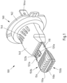
- Fig. 1 shows an example of a lighting device 100 according to an exemplary embodiment of the invention.
- the lighting device 100 is an LED retrofit which contains an adapter means 160 to connect the LED retrofit to an automotive headlight unit.
- the adapter means 160 comprises an adapter ring 162 and two power pins 164a and 164b for electrical connection (only pin 164a being visible in Fig. 1 ).
- the support structure 110 supports a top-contact LED 120a, which is an example of a light emitting element.
- a further LED 120a is provided on the opposing side of the support structure 110 which is not visible in the figure.
- the LED 120a is electrically connected through ribbon-bonding connections 122a, 122b to respective sides (carriers) 110a, 110b of the support structure 110 for electrically connecting LED 120a.
- a cooling element 150b with eight cooling fins 154 (cooling extensions) is arranged on each of sides 1 10a, 110b of the support structure, the cooling fins being arranged such that a main plane of the cooling fins (cooling extensions) is arranged essentially parallel to a main direction of extension of the support structure 110 (corresponding to a direction along a largest extension of the support structure 110).
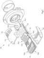
- An air source 133 and further cooling elements 150a are shown in Fig. 2 , whereby in the shown example the air source is a radial fan 133 as described further herein. As shown in Fig.
- a housing 140 is provided surrounding part of support structure 110 and the cooling elements 150a, the housing 140 being tapered towards the LED 120a.
- the housing 140 comprises ventilation slits 146 (an arrangement of slits) to ensure sufficient air supply for radial fan 133 enclosed by housing 140.
- the lighting device 100 further comprises driver electronics configured to operate electronic components of the lighting device, e.g. the at least one air source and/or the at least one light emitting element 120 and/or further electronic components depending on a particular application.
- driver electronics may be arranged on the support structure 110 and/or (e.g. in case that driver electronics comprise sub-components) on a separate PCB.
- Fig. 2 shows an exploded view of the lighting device 100 of Fig. 1 .
- an air flow that can be generated by radial fan 133 exits a housing of radial fan 133 at its side directly adjacent to cooling element 150a to pass through cooling fins 154 of cooling element 150a over LED 120a and further through cooling fins 154 of cooling element 150b such that a cooling effect of the air flow on the support structure 110, which acts not only as a support for the LED 120a but also as a heat sink for the lighting device, is further enhanced by cooling elements 150a and 150b.
- respective radial fans (air sources) 133 are provided on either side of the support structure 110.
- the cooling fins 154 have respective inclined edges (inclined section 156) being inclined away from the LED (a respective height decreases towards the LED). In this way, cooling fins 154 can enhance a cooling effect of the support structure while at the same time, an obstruction of light emitted from LED 120a is prevented.
- housing 140 has two mutually opposing parts respectively surrounding or enclosing at least part of the support structure 110 and the cooling fins 150a, the housing 140 being arranged to guide at least part of the air flow generated by the at least one air source (radial fan 133) in between the support structure 110 and the housing 140.
- the support structure 110 is formed from a heat conductive material such as a metal, in particular aluminum or copper to facilitate a heat flow away from the LED 120a.
- the advantageous cooling effect provided by support structure 110 with cooling elements 150a, 150b allows for housing 140 to be fabricated from a material that does not need to be heat conductive, e.g. from a plastic material, and thus allows for a simplified construction of the lighting device.
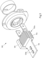
- Fig. 3 shows another example of a lighting device 100 according to another exemplary embodiment of the invention.
- the support structure 110 is a metal core printed circuit board (MCPCB), whereby two LEDs 120b are soldered onto and electrically connected to the MCPCB. Two further LEDs 120b are provided on the opposing side of the support structure 110 which are not visible in the figure.
- a cooling element 150a with seven cooling fins 154 (cooling extensions) is arranged on both sides of the support structure 110. As shown in Fig. 3 , the cooling fins 154 extend from the support structure being formed as integral components of the support structure.
- An axial fan 135 air source is mounted to the side of the support structure 110 next (adjacent) to the cooling element 150a.
- FIG. 3 does not show a housing, a housing as shown in Figs. 1 or 2 , suitably adapted, may be provided.
- Figs. 4a-d show cross-sectional views of further examples of a lighting device 100 according to exemplary embodiments of the invention. As mentioned, like reference numerals indicate the same components.
- Figs. 4a and 4b may correspond to cross-sectional views of the examples shown in Figs. 1 and 2 , whereby in the shown example the radial fans 133 are replaced by axial fan 135.
- the cooling elements 150a, 150b comprise cooling fins (cooling extensions) 154 which are connected to the support structure 110. As in the example of Fig. 1 , eight cooling fins 154 may be provided on either side of the LED 120, only one respective one of which is visible in the figure.
- the axial fan 135 (air source) is mounted next to the cooling elements 150a with an airflow 170 guided by the cooling extensions 154 towards the LED 120. After passing the cooling elements 150a and the LED 120 the air flow further passes light emitting elements 120 and cooling elements 150b to enable a further cooling of the support structure.
- Fig. 4b shows the arrangement of Fig. 4a further being provided with a transparent tube (housing) 142.
- the transparent tube 142 can be a member with an essentially circular cross-section being provided surrounding the support structure 110 and the cooling elements 150a, 150b.
- the transparent tube 142 can be provided with further cross-sections such as elliptical or rectangular cross-sections.
- Figs. 4c and 4d show respective further embodiments of lighting device 100. While in Figs. 4a and 4b , cooling fins 154a and 154b are arranged with a main plane of the cooling fins being arranged essentially parallel to a main direction of extension of the support structure 110, in Figs. 4c and 4d , the cooling fins 154a and 154b are arranged on the support structure 110 such that a main plane of the cooling fins (cooling extensions) is arranged essentially perpendicular to a main direction of extension of the support structure 110. Such arrangement of the cooling fins thus corresponds to an arrangement of cooling fins as also illustrated in Fig. 3 . Likewise, as in the example of Fig.
- an axial fan 135 is mounted at the side of the support structure 110 (schematically indicated by circle 135) next to the cooling elements 150a.
- an air flow generated by the axial fan 135 in the examples of Figs. 4c and 4d guided along the cooling fins 154a, 154b is not primarily guided towards the LED 120.
- the cooling fins 154a may vary in size to adapt to the geometry of the fan 135 and/or to the generated air flow. This enables an efficient use of the air flow by maximizing the surface of the cooling elements.
- a height of cooling fins at respective edges of an arrangement of cooling fins 154a shown in Fig. 4c is minimized which allows for a simpler placement of cooling fins at a center of the arrangement upon fabrication or assembly of the lighting device.
- Fig. 4d essentially corresponds to the example of Fig. 4c .
- Fig. 4d an exemplary embodiment of the lighting device 100 is shown where the cooling fins 154b as shown in Fig. 4d are essentially equally high.
- the height of the cooling fins 154b is compromised to allow for both a satisfactory cooling effect while at the same time allowing for a simple fabrication of the fins.
- further an excessive height of cooling fins is avoided which contributes to stability of the overall arrangement of cooling fins 154b.
- Lighting device 100 Support structure 110 Electrical contact side 110a, 110b Light emitting element 120a, 120b LED top connection 122a, 122b Radial fan 133 Axial fan 135 Housing 140 Transparent tube 142 Tapered section 144 Ventilation slit 146 Cooling element 150a, 150b Cooling extension 154, 154a, 154b Adapter means 160 Adapter ring 162 Power pins 164a, 164b Air flow 170
Landscapes
- Engineering & Computer Science (AREA)
- General Engineering & Computer Science (AREA)
- Physics & Mathematics (AREA)
- Microelectronics & Electronic Packaging (AREA)
- Optics & Photonics (AREA)
- Arrangement Of Elements, Cooling, Sealing, Or The Like Of Lighting Devices (AREA)
Abstract
Description
- The present disclosure relates to a lighting device such as e.g. a light source for an automotive headlight.
- Lighting devices such as halogen lamps have been used as light sources for automotive headlights for many years. However, recent advances in light-emitting diode, LED, technology have enabled developments of lighting devices providing replacements for halogen lamps. Such lighting devices replacing halogen lamps may be referred to as LED retrofits.
- While LED retrofits often allow for efficient halogen lamp replacements, at least in certain situations, heat usually produced by operating LEDs has to be guided away from operating LEDs. To this end, heatsinks may be used, i.e. components of the corresponding LED retrofits that usually are in thermal contact with corresponding LEDs and that are formed from a material with sufficiently high thermal conductivity, to guide heat away from the LEDs when operating. In addition, it is desirable to provide LED retrofits of substantially similar dimension as compared to typical halogen lamps.
- In view of this, it is an object of the present invention to provide a lighting device with an improved solution for guiding heat away from operating LEDs of the lighting device. It is a further object of the present invention, to enable a lighting device with improved heat guiding capability having dimensions comparable to existing halogen lamps.
- According to a first aspect of the present invention, a lighting device is provided, comprising: a housing; a support structure arranged at least in part within at least part of the housing; at least one light emitting element arranged on the support structure; at least one cooling element arranged on the support structure; at least one air source configured to generate an air flow, the at least one air source being arranged at the lighting device such that at least part of an air flow generated by the at least one air source passes along at least part of a surface of the at least one cooling element.
- According to a second aspect of the present invention, a method of manufacturing a lighting device, in particular of a lighting device according to the first aspect, is provided, the method comprising: providing a housing, providing a support structure arranged at least in part within at least part of the housing, providing at least one light emitting element arranged on the support structure, providing at least one air source configured to generate an air flow, the at least one air source being arranged at the lighting device such that at least part of an air flow generated by the at least one air source passes along at least part of a surface of the at least one cooling element.
- According to a third aspect of the present invention, an automotive headlight is provided, comprising a lighting device according to the first aspect.
- Exemplary embodiments of the first, second and third aspect of the invention may have one or more of the properties described below.
- In an exemplary embodiment, the lighting device is a light source for an automotive headlight, e.g. a retrofit lamp for automotive headlight applications. Thus, as explained further herein, in an exemplary embodiment, the at least one light emitting element is or comprises at least one light-emitting diode, LED. In addition, in an exemplary embodiment, the lighting device is provided with suitable means to be mounted to a vehicle, e.g. a car, a motorcycle or a truck. To this end, the lighting device comprises in particular adapter means for mounting the lighting device. In an exemplary embodiment, the adapter means comprises an adapter ring of dimensions according to corresponding regulations and standards, e.g. according to UNECE RE5 and/or R37 and/or IEC 60061.The adapter means may be part of or be connected to the housing of the lighting device. The housing may be a component of the lighting device that may provide in particular protection for one or more further components of the lighting device. The support structure being arranged at least in part within at least part of the housing, in an exemplary embodiment, at least in mounted condition of the lighting device, the housing encloses at least part of the support structure. In addition or alternatively, in an exemplary embodiment, at least in mounted condition of the lighting device, the housing encloses at least part of the at least one cooling element. It is to be noted that in an exemplary embodiment, the housing and the support structure are separate components of the lighting device. In this way, advantageous flexibility is provided in particular for attributing a main heat guiding function to the support structure, enabling a construction of the housing independently of this function, thereby enabling in particular fabrication of the housing from a different material.
- While in certain embodiments, the housing may be formed of a material corresponding to the material of the support structure, e.g. from a metal, embodiments of the present disclosure attribute a main heat guiding function to the support structure, which may thus correspond to a main heat sink of the lighting device. In this way, it becomes possible to form at least part of the housing from a different material, such as a plastic material. Thus, in an exemplary embodiment, the housing may thus comprise a material with a thermal conductivity of less than 385 W/(m·K), in particular less than 205 W/(m·K), in particular less than 20 W/(m·K). In an exemplary embodiment, the housing is formed at least in part from a plastic material and/or from a glass material and/or from a ceramic material and/or from polymethylmethacrylate (PMMA), e.g. so-called "LED grade" PMMA, and/or transparent silicones.
- As mentioned, a main heat guiding function may be assigned to the support structure. Thus, in an exemplary embodiment, the support structure of the lighting device at least in part corresponds to or comprises a heatsink. The support structure may thus support cooling of the at least one light emitting element. In other words, in an exemplary embodiment, the support structure is configured to guide heat generated by the at least one light emitting element at least away from the at least one light emitting element. In an exemplary embodiment, the support structure may be formed, at least in part, from a heat conductive material, in particular from a metal. In an exemplary embodiment, the support structure may thus comprise at least one material selected from copper, aluminum, and/or alloys of copper and/or aluminum. Use of such material may be advantageous in that heat is guided away from the at least one light emitting element in a particularly efficient manner. In an exemplary embodiment, the support structure may be formed by cold forming, extrusion molding, by turning processes and/or by milling processes. In an exemplary embodiment, the support structure may be formed as aluminum die cast. Extrusion molding is a process that allows forming the support structure in a non-complex way nevertheless allowing for sufficient production quality. At the same time, further components such as cooling elements provided on the support structure may be formed in combination with the support structure in a single production step.
- As mentioned, the at least one light emitting element is arranged on the support structure. Thus, in an exemplary embodiment, the support structure comprises a mounting surface configured to support and/or hold the at least one light emitting element. For example, the support structure may in an exemplary embodiment, comprise or correspond to, at least in part, an essentially flat member, e.g. with an elongated, e.g. essentially rectangular, shape, forming a mounting surface for supporting the at least one light emitting element. The lighting device may comprise more than one light emitting element and more than one cooling element, whereby one or more light emitting elements and/or one or more cooling elements may be provided on opposing sides of the support structure, the opposing sides facing opposing directions. Thus, in an exemplary embodiment, the support structure comprises two sides with at least one light emitting element and/or at least one cooling element being arranged on either one of the two sides of the support structure. The support structure may thus comprise two mounting surfaces on opposing sides facing opposing directions for mounting, wherein at least one light emitting element and/or at least one cooling element is provided on a respective one of the two mounting surfaces.
- The support structure may further provide electrical connection to the at least one light emitting element and/or to further electrical components provided on the support structure as needed. Thus, in an exemplary embodiment, the support structure at least comprises one or more contact portions or regions for electrically contacting the at least one light emitting element. For example, in an exemplary embodiment, the support structure at least in part corresponds to or comprises a printed circuit board, PCB, and/or a printed wiring board, PWB. As a result, in an exemplary embodiment, the at least one light emitting element is electrically connected to an electrical power supply and/or electrically controlled via the support structure, in particular via the PCB/ PWB, and/or a leadframe and/or a metal piece. In an exemplary embodiment, the at least one light emitting element may comprise a SMD-LED ("surface-mounted-device"-LED) and may, in an exemplary embodiment, be soldered to the PCB/PWB. In an exemplary embodiment, an LED driving circuit and/or fan driver electronics and/or a constant current source is/are arranged on the support structure, e.g. on the PCB/PWB.
- In an exemplary embodiment, the support structure corresponds to or comprises at least one metal carrier. In an exemplary embodiment, the support structure comprises two metal carriers, being mutually electrically isolated. In this case, electrical contacts of the at least one light emitting element may respectively be electrically connected to corresponding ones of the at least two electrical carriers, in particular via ribbon-bonding.
- In an exemplary embodiment, the at least one light emitting element is a light emitting diode (LED), for example a light emitting diode configured for emitting light in a color temperature range of 2500-7500K, in particular of 4000-7000K, in particular of 5000-6500K. Such light emitting diodes are suitable light sources in particular for automotive applications as they enable emitting light of suitable color at advantageous brightness. Thus, in an exemplary embodiment, the at least one light emitting element is configured to emit light at a luminous flux of 600-2400 lumen (1m), in particular of 1350-1650 lm. Luminous flux ranges suitable for exemplary embodiments may be taken from UNECE RE5 or R37 for respective examples of a halogen lamp the lighting device, in particular an LED lamp, shall replace.
- In an exemplary embodiment, at least one of or both of the at least one light emitting element and the at least one cooling element are arranged in direct contact with the support structure, in particular wherein at least one of or both of the at least one light emitting element and the at least one cooling element are connected to the support structure via soldering and/or using an adhesive. In other words, in an exemplary embodiment, the at least one light emitting element and/or the at least one cooling element is arranged on the support structure with no further components of the lighting device being arranged in between the at least one light emitting element/the at least one cooling element and the support structure. Only for example attachment components such as glue, solder and/or parts of attachment means may be present in in between the at least one light emitting element/the at least one cooling element and the support structure. Alternatively or in addition, in an exemplary embodiment, the at least one light emitting element and/or the at least one cooling element is soldered and/or riveted and/or screwed to the support structure. Thus, the at least one light emitting element and/or the at least one cooling element is in direct thermal contact with the support structure. Heat may thus be transferred from the at least one light emitting element to the support structure and to the at least one cooling element in an efficient and direct manner.
- In an exemplary embodiment, the support structure further comprises a printed circuit board (PCB), wherein the at least one of or both of the at least one light emitting element and the at least one cooling element are arranged in direct contact with the PCB, in particular wherein at least one of or both of the at least one light emitting element and the at least one cooling element are attached to the PCB via soldering and/or using an adhesive.
- In order to support a cooling effect of the support structure, the lighting device is provided with the at least one air source, e.g. a fan, for generating an air flow in particular along and/or in contact with at least part of a surface of the at least one cooling element. To this end, in an exemplary embodiment, the at least one air source may e.g. be provided adjacent to the at least one cooling element. Thus, in order to support a cooling effect of the support structure, heat may be transferred from the support structure to the cooling element, which may then transfer at least part of the heat on to the air flow. The air flow may thus remove at least part of the heat generated by the at least one light emitting element.
- In an exemplary embodiment, the at least one air source configured to generate an air flow is or comprises a fan, for example an axial fan with an air flow being generated and output in a direction essentially parallel to the axis of rotation of the fan. Alternatively, such fan may be a radial fan with an air flow being generated and output in a direction essentially vertical to the axis of rotation of the fan. In an exemplary embodiment, the at least one air source may be arranged on the support structure and/or the at least one air source may be electrically connected to the electrical power supply via the support structure, e.g. via the PCB/PWB and or via the at least two electrical carriers. For example, a radial fan may be arranged on the support structure with the plane of rotation being essentially parallel to a surface of the support structure. In an exemplary embodiment, the at least one air source may be arranged on a component of the lighting device other than the support structure, e.g. in an exemplary embodiment, the at least one air source is supported by the adapter means. In an exemplary embodiment, the housing contains structures to guide the air flow to and from the fan. In an exemplary embodiment, the at least one air source is attached to the housing. In other words, in an exemplary embodiment, the housing is configured to hold or support the at least one air source.
- In an exemplary embodiment, the at least one air source is arranged such that an air flow generated by the at least one air source has a general direction towards the at least one cooling element and/or towards the at least one light emitting element. While it is thus possible that the air flow is generated in a direction towards the at least one light emitting element, in an exemplary embodiment, the at least one air source is arranged on the support structure adjacent to the at least one cooling element, wherein a main direction of an air flow generated by the at least one air source is essentially perpendicular to a direction from the at least one cooling element (e.g. from an arrangement of one or more cooling elements) to the at least one light emitting element (e.g. to an arrangement of one or more light emitting elements).
- The at least one cooling element is provided on the support structure and thus enhances an overall surface of the support structure which serves for guiding away heat from the at least one light emitting element. The at least one cooling element thus enhances a cooling effect and an effect of the support structure functioning as heat sink of the lighting device. Heat generated by the at least one light emitting element in operation may thus be transferred to the support structure and thus to the at least one cooling element. This heat may then be transferred from the at least one cooling element (and additionally from the support structure) to at least part of the air flow generated by the at least one air source. Thus, increasing a surface provided for cooling the at least one light emitting element by providing the at least one cooling element enables more heat to be transferred from the at least one cooling element to the air flow.
- In an exemplary embodiment, the at least one cooling element may be formed, at least in part, from a heat conductive material, in particular from a metal. In an exemplary embodiment, the at least one cooling element may thus comprise at least one material selected from copper, aluminum, and/or alloys of copper and/or aluminum. Use of such material may be advantageous in that heat is transferred from the support structure to the at least one cooling element in a particularly efficient manner. Use of such material may further be advantageous in that heat is transferred from the at least one cooling element to the part of the air flow that passes along at least part of a surface of the at least one cooling element in a particularly efficient manner. In an exemplary embodiment, the at least one cooling element may be formed, at least in part, from extruded rods, in particular comprising suitable alloys of aluminum. In an exemplary embodiment, the at least one cooling element may be formed, at least in part, from bent or stamped sheet metal, in particular comprising aluminum and/or copper.
- In an exemplary embodiment, the at least one air source is arranged essentially adjacent to the at least one cooling element. In other words, in an exemplary embodiment, the at least one air source is arranged next to the at least one cooling element with no further component of the lighting device being arranged in between the at least one air source and the at least one cooling element. Thereby, in an exemplary embodiment, a distance between the at least one air source and the at least one cooling element is smaller than 10 mm, in particular smaller than 5 mm, in particular smaller than 3 mm, in particular smaller than 2 mm. The at least one cooling element being arranged essentially adjacent to the at least one air source, an air flow generated by the at least one air source passes essentially immediately along at least part of the surface of the at least one cooling element such that a comparably large fraction of air generated by the at least one air source is directed along at least part of the surface of the at least one cooling element which enables an efficient cooling of the support structure via the at least one cooling element.
- In an exemplary embodiment, the housing comprises at least one opening arranged at the housing such that in operation of the at least one air source, an air flow generated by the at least one air source is fed with air via the at least one opening. In an exemplary embodiment, the housing comprises an arrangement of openings, e.g. holes or slits. Thus, the air source may be arranged inside the housing while maintaining sufficient air supply for the generation of an air flow.
- In an exemplary embodiment, the at least one light emitting element and the at least one cooling element are arranged on a same surface, e.g. the mounting surface, of the support structure. Thus, the at least one light emitting element and the at least one cooling element being on a same surface, a direct flow of heat from the at least one light emitting element to the at least one cooling element via the support structure is enabled, which is not disturbed by further elements of the lighting device. A particularly efficient heat transfer may thus be provided.
- In an exemplary embodiment, the at least one cooling element is arranged essentially adjacent to the at least one light emitting element. In other words, in an exemplary embodiment, the at least one cooling element is arranged next to the at least one light emitting element with no further component of the lighting device being arranged in between the at least one cooling element and the at least one light emitting element. Thereby, in an exemplary embodiment, a distance between the at least one cooling element and the at least one light emitting element is smaller than 10 mm, in particular smaller than 5 mm, in particular smaller than 3 mm, in particular smaller than 2 mm. The at least one cooling element being arranged essentially adjacent to the at least one light emitting element, heat generated by the at least one light emitting element can be transferred to the at least one cooling element via the support structure in an especially efficient manner.
- In an exemplary embodiment, the at least one cooling element is formed as an integral component with the support structure. Thereby, heat can be transferred efficiently from the support structure to the at least one cooling element. In an exemplary embodiment, the at least one cooling element is formed by extrusion molding in a single production step with the support structure.
- In an exemplary embodiment, at least part of the housing is tapered in at least one dimension towards the at least one light emitting element. In other words, in an exemplary embodiment, at least a section of the housing comprises a cross-section decreasing in size towards the at least one light emitting element. Thereby, the housing may in an exemplary embodiment comprise a tubular section having an essentially circular, an essentially elliptical, an essentially rectangular or an irregular cross-section. The housing may thus reduce the space in between the support structure and the housing and may thus act in a nozzle-like way not only guiding but also intensifying an air flow onto the support structure, in particular within an area of the support structure supporting the at least one light emitting element thus facilitating an improved cooling effect in particular in this area.
- In an exemplary embodiment, at least part of the housing at least partly surrounds at least part of the at least one cooling element. In other words, at least part of the housing at least partly encloses or encapsulates at least part of the at least one cooling element. Thus, the housing confines at least part of an air flow generated by the at least one air source onto the at least one cooling element increasing the cooling effect of the air flow.
- In an exemplary embodiment, the housing is at least in part formed from a material transparent for at least part of light emitted from the at least one light emitting element, e.g. a glass material or a transparent plastic material. The housing may for example be formed at least in part as an at least partly transparent tube.
- In an exemplary embodiment, the cooling element comprises at least one cooling extension that extends from the support structure and/or from a base member provided on the support structure. For example, the cooling extension comprises or corresponds to a cooling fin comprising an essentially rectangular or triangular cooling surface being arranged essentially parallel to a main direction of the air flow. In an exemplary embodiment, the at least one cooling extension comprises or corresponds to a cooling pin, e.g. of essentially round or rectangular shape comprising a height of the cooling pin at least three times larger, in particular at least five times larger, in particular at least ten times larger than a width and length of the cooling pin. In an exemplary embodiment, the base member and the at least one cooling extension are formed as an integral component. For example, the base member may connect and support two or more cooling extensions. Thus, heat can be transferred from the base member to the cooling extensions efficiently and physical stability of the cooling element may be improved.
- In an exemplary embodiment, the at least one cooling element further comprises at least two cooling extensions, wherein the at least two cooling extensions are arranged on the support structure such that at least part of the air flow generated by the at least one air source passes through the at least two cooling extensions. In other words, in an exemplary embodiment, the at least one cooling element further comprises at least two cooling extensions mutually separated by a cooling gap. Alternatively or in addition, in an exemplary embodiment, at least two cooling extensions are separated by a slit extending within the cooling base. Thus, the at least two cooling extensions further enhance a cooling surface of the at least one cooling element, thereby improving the transfer of heat from the at least two cooling extensions to the air flow.
- In an exemplary embodiment, the at least one cooling extension comprises an essentially flat shape. In other words, in an exemplary embodiment, the at least one cooling extension corresponds to an essentially flat member, e.g. the flat member comprising a length and/or a height at least three times larger, in particular at least five times larger, in particular at least ten times larger than a width of the essentially flat member.
- In an exemplary embodiment, a main plane of the cooling extension is arranged essentially perpendicular or essentially parallel to a main direction of extension of the support structure (corresponding to a direction along a largest extension of the support structure). In an exemplary embodiment, the main plane of the cooling extension corresponds to a main surface of the essentially flat member, spanned by its height and its length. In an exemplary embodiment, the main direction of extension of the support structure corresponds to a direction along the largest extension of the support structure.
- In an exemplary embodiment, at least two cooling extensions are arranged on the support structure and/or on the base member such that main planes of the at least two cooling extensions are essentially mutually parallel. Thereby, being essentially mutually parallel is to be understood such that an angle formed by the at least two cooling extensions is smaller than 10°, in particular smaller than 5°, in particular smaller than 2°.
- In an exemplary embodiment, a main plane of the at least one cooling extension is arranged essentially perpendicular to the main direction of extension of the support structure and the at least one cooling extension has an essentially rectangular shape. The at least one cooling extension may in this example form an arrangement of two or more cooling extensions with essentially rectangular shape. With the rectangular shape, a cooling surface provided by the cooling extensions is maximized, whereby the arrangement can be provided on the support structure with sufficient distance from the at least one light emitting element in order not to obstruct light emitted therefrom.
- In an exemplary embodiment, a main plane of the at least one cooling extension is arranged essentially parallel to the main direction of extension of the support structure and the at least one cooling extension is at least in part inclined along the main direction of extension of the support structure. In this example, the at least one cooling extension may be provided with its inclination such that its height decreases along the main direction of the support structure towards the at least one light emitting element. In this way, the overall cooling surface of the support structure may be enhanced by the at least one cooling element, while an obstruction of light emitted from the at least one light emitting element is prevented. Thereby, for example, an inclination with respect to the support structure may be smaller than 50°, in particular smaller than 40°, in particular smaller than 30°.
- In an exemplary embodiment, respective cooling elements comprising respective cooling extensions are provided on opposing sides of the at least one light emitting element, the respective cooling extensions being inclined in a direction away from a portion of the support structure supporting the at least one light emitting element. Thus, at least one cooling element may be provided on the support structure on either side of the at least one light emitting element, such that an air flow generated by the at least one air source that has passed a cooling element on one side of the at least one light emitting element and the at least one light emitting element, may still also pass the at least one light emitting element on the other side of the at least one light emitting element. Such configuration of at least two cooling elements further enhances a cooling surface of the support structure and may further enable use of the air flow in an improved manner. Thereby, the respective cooling extensions are inclined in a direction away from a portion of the support structure supporting the at least one light emitting element. In other words, a respective cooling extension has a smaller height at a side of the respective cooling element facing said portion of the support structure supporting the at least one light emitting element then a height at a side of the respective cooling element facing away from said portion of the support structure supporting the at least one light emitting element. In this way, obstruction of light emitted from the at least one light emitting element is advantageously prevented.
- In an exemplary embodiment, at least two of the at least one cooling extension have different heights with respect to the support structure. In an exemplary embodiment, the height of the at least one cooling extension corresponds to a height of the at least one cooling extension in a direction essentially perpendicular to a main plane of the support structure. By adapting heights of two or more cooling extensions e.g. in a case in which a main plane of corresponding cooling extensions is arranged essentially perpendicular to the main direction of extension of the support structure, it becomes possible to adapt the respective heights to a light emission of the at least one light emitting element, in order to reduce obstruction of light emitted from the at least one light emitting element. More generally, irrespectively of an orientation of the cooling extensions, providing cooling extensions of an arrangement of cooling extensions at edges of the arrangement smaller may facilitate a mounting, e.g. soldering, of cooling extensions inside of the arrangement.
- Thus, in an exemplary embodiment, the lighting device comprises an arrangement of at least three cooling extensions, wherein the arrangement comprises two outermost cooling extensions at opposing sides of the arrangement, wherein a height of at least one of the two outermost cooling extensions is a smallest height among heights of the at least three cooling extensions. Thus, an especially easy fabrication of the arrangement is possible.
- In an exemplary embodiment, heights of at least two of the at least one cooling extension continuously vary from one side of the arrangement towards the opposing side of the arrangement, firstly increasing towards a maximum height before decreasing to a smallest height. For example, in case of only three cooling extensions, a central cooling extension may be provided with a largest height, while the two neighboring cooling extensions may be provided with a - for example same - smaller height.
- In an exemplary embodiment, the method of manufacturing a lighting device further comprises providing the at least one light emitting element and the at least one cooling element onto the support structure in a single manufacturing step, in particular via soldering. In an exemplary embodiment, at least one light emitting element, the at least one cooling element and at least one further component of the lighting device, e.g. fan driver electronics, are provided onto the support structure in a single manufacturing step. In an exemplary embodiment, the at least one light emitting element and the at least one cooling element are provided onto the support structure via a surface-mount technology (SMT) process.
- The features and example embodiments of the invention described above may equally pertain to the different aspects according to the present invention. In particular, with the disclosure of features relating to the lighting device according to the first aspect, also corresponding features relating to the automotive headlight according to the second aspect are disclosed.
- It is to be understood that the presentation of embodiments of the invention in this section is merely exemplary and non-limiting.
- Other features of the present invention will become apparent from the following detailed description considered in conjunction with the accompanying drawings. It is to be understood, however, that the drawings are designed solely for purposes of illustration and not as a definition of the limits of the invention, for which reference should be made to the appended claims. It should be further understood that the drawings are not drawn to scale and are merely intended to conceptually illustrate the structures and procedures described herein.
- Examples of the invention will now be described in detail with reference to the accompanying drawings, in which:
- Fig. 1
- exemplarily illustrates a lighting device according to an embodiment of the invention;
- Fig. 2
- illustrates a view of the lighting device of
Fig. 1 without the housing; - Fig. 3
- exemplarily illustrates a view without the housing of a lighting device according to an embodiment of the invention;
- Figs. 4 a-d
- illustrate cross-sectional side-views of lighting devices according to embodiments of the invention;
- It is noted that throughout the figures, like reference numerals indicate corresponding or equal components.
-
Fig. 1 shows an example of alighting device 100 according to an exemplary embodiment of the invention. Thelighting device 100 is an LED retrofit which contains an adapter means 160 to connect the LED retrofit to an automotive headlight unit. The adapter means 160 comprises anadapter ring 162 and twopower pins 164a and 164b for electrical connection (only pin 164a being visible inFig. 1 ). Thesupport structure 110 supports a top-contact LED 120a, which is an example of a light emitting element. A further LED 120a is provided on the opposing side of thesupport structure 110 which is not visible in the figure. The LED 120a is electrically connected through ribbon-bonding connections support structure 110 for electrically connecting LED 120a. Acooling element 150b with eight cooling fins 154 (cooling extensions) is arranged on each of sides 1 10a, 110b of the support structure, the cooling fins being arranged such that a main plane of the cooling fins (cooling extensions) is arranged essentially parallel to a main direction of extension of the support structure 110 (corresponding to a direction along a largest extension of the support structure 110). Anair source 133 andfurther cooling elements 150a are shown inFig. 2 , whereby in the shown example the air source is aradial fan 133 as described further herein. As shown inFig. 1 , ahousing 140 is provided surrounding part ofsupport structure 110 and thecooling elements 150a, thehousing 140 being tapered towards the LED 120a. Thehousing 140 comprises ventilation slits 146 (an arrangement of slits) to ensure sufficient air supply forradial fan 133 enclosed byhousing 140. - While not shown in the figures, in an exemplary embodiment, the
lighting device 100 further comprises driver electronics configured to operate electronic components of the lighting device, e.g. the at least one air source and/or the at least onelight emitting element 120 and/or further electronic components depending on a particular application. Such driver electronics may be arranged on thesupport structure 110 and/or (e.g. in case that driver electronics comprise sub-components) on a separate PCB. -
Fig. 2 shows an exploded view of thelighting device 100 ofFig. 1 . As can be taken from this figure, an air flow that can be generated byradial fan 133 exits a housing ofradial fan 133 at its side directly adjacent tocooling element 150a to pass through coolingfins 154 ofcooling element 150a over LED 120a and further through coolingfins 154 ofcooling element 150b such that a cooling effect of the air flow on thesupport structure 110, which acts not only as a support for the LED 120a but also as a heat sink for the lighting device, is further enhanced by coolingelements Fig. 2 , respective radial fans (air sources) 133 are provided on either side of thesupport structure 110. - As shown in
Fig. 2 , the coolingfins 154 have respective inclined edges (inclined section 156) being inclined away from the LED (a respective height decreases towards the LED). In this way, coolingfins 154 can enhance a cooling effect of the support structure while at the same time, an obstruction of light emitted from LED 120a is prevented. - In the shown example,
housing 140 has two mutually opposing parts respectively surrounding or enclosing at least part of thesupport structure 110 and thecooling fins 150a, thehousing 140 being arranged to guide at least part of the air flow generated by the at least one air source (radial fan 133) in between thesupport structure 110 and thehousing 140. In thetapered section 144 ofhousing 140, an inner surface ofhousing 140 follows the inclination ofinclined section 156. In the shown example, thesupport structure 110 is formed from a heat conductive material such as a metal, in particular aluminum or copper to facilitate a heat flow away from the LED 120a. The advantageous cooling effect provided bysupport structure 110 withcooling elements housing 140 to be fabricated from a material that does not need to be heat conductive, e.g. from a plastic material, and thus allows for a simplified construction of the lighting device. -
Fig. 3 shows another example of alighting device 100 according to another exemplary embodiment of the invention. In this example, thesupport structure 110 is a metal core printed circuit board (MCPCB), whereby twoLEDs 120b are soldered onto and electrically connected to the MCPCB. Twofurther LEDs 120b are provided on the opposing side of thesupport structure 110 which are not visible in the figure. Acooling element 150a with seven cooling fins 154 (cooling extensions) is arranged on both sides of thesupport structure 110. As shown inFig. 3 , the coolingfins 154 extend from the support structure being formed as integral components of the support structure. An axial fan 135 (air source) is mounted to the side of thesupport structure 110 next (adjacent) to thecooling element 150a. An air flow generated by theaxial fan 135 thus passes through the cooling extensions without being obstructed by any further components of the lighting device that otherwise may be placed in betweenaxial fan 135 andcooling element 150a. It is noted that whileFig. 3 does not show a housing, a housing as shown inFigs. 1 or2 , suitably adapted, may be provided. -
Figs. 4a-d show cross-sectional views of further examples of alighting device 100 according to exemplary embodiments of the invention. As mentioned, like reference numerals indicate the same components. -
Figs. 4a and 4b may correspond to cross-sectional views of the examples shown inFigs. 1 and2 , whereby in the shown example theradial fans 133 are replaced byaxial fan 135. Thecooling elements support structure 110. As in the example ofFig. 1 , eight coolingfins 154 may be provided on either side of theLED 120, only one respective one of which is visible in the figure. The axial fan 135 (air source) is mounted next to thecooling elements 150a with anairflow 170 guided by thecooling extensions 154 towards theLED 120. After passing thecooling elements 150a and theLED 120 the air flow further passeslight emitting elements 120 andcooling elements 150b to enable a further cooling of the support structure. -
Fig. 4b shows the arrangement ofFig. 4a further being provided with a transparent tube (housing) 142. Thetransparent tube 142 can be a member with an essentially circular cross-section being provided surrounding thesupport structure 110 and thecooling elements transparent tube 142 can be provided with further cross-sections such as elliptical or rectangular cross-sections. By thus encasing thesupport structure 110, theLEDs 120 andcooling elements transparent tube 142 confines an air flow generated byfan 135 and indicated byarrows 170 to these components and thus prevents loss of air for cooling. In other words,transparent tube 142 further enhances the cooling effect by preventing theair flow 170 from diverging beyond the surface oftube 142. -
Figs. 4c and 4d show respective further embodiments oflighting device 100. While inFigs. 4a and 4b , coolingfins support structure 110, inFigs. 4c and 4d , the coolingfins support structure 110 such that a main plane of the cooling fins (cooling extensions) is arranged essentially perpendicular to a main direction of extension of thesupport structure 110. Such arrangement of the cooling fins thus corresponds to an arrangement of cooling fins as also illustrated inFig. 3 . Likewise, as in the example ofFig. 3 , also in the examples ofFigs. 4c and 4d , anaxial fan 135 is mounted at the side of the support structure 110 (schematically indicated by circle 135) next to thecooling elements 150a. Thus, as opposed to the examples ofFigs. 1 ,2 ,4a and 4b , an air flow generated by theaxial fan 135 in the examples ofFigs. 4c and 4d guided along the coolingfins LED 120. As can be taken fromFig. 4c , the coolingfins 154a may vary in size to adapt to the geometry of thefan 135 and/or to the generated air flow. This enables an efficient use of the air flow by maximizing the surface of the cooling elements. At the same time, a height of cooling fins at respective edges of an arrangement ofcooling fins 154a shown inFig. 4c is minimized which allows for a simpler placement of cooling fins at a center of the arrangement upon fabrication or assembly of the lighting device. - The example of
Fig. 4d essentially corresponds to the example ofFig. 4c . InFig. 4d , an exemplary embodiment of thelighting device 100 is shown where the coolingfins 154b as shown inFig. 4d are essentially equally high. In this example, the height of the coolingfins 154b is compromised to allow for both a satisfactory cooling effect while at the same time allowing for a simple fabrication of the fins. In this example, further an excessive height of cooling fins is avoided which contributes to stability of the overall arrangement of coolingfins 154b.LIST OF REFERENCE SIGNS: Lighting device 100 Support structure 110 Electrical contact side 110a, 110b Light emitting element 120a, 120b LED top connection 122a, 122b Radial fan 133 Axial fan 135 Housing 140 Transparent tube 142 Tapered section 144 Ventilation slit 146 Cooling element 150a, 150b Cooling extension 154, 154a, 154b Adapter means 160 Adapter ring 162 Power pins 164a, 164b Air flow 170
Claims (15)
- A lighting device (100) comprising:a housing (140);a support structure (110) arranged at least in part within at least part of the housing (140);at least one light emitting element (120) arranged on the support structure (110);at least one cooling element (150) arranged on the support structure (110);at least one air source configured to generate an air flow, the at least one air source being arranged at the lighting device (100) such that at least part of an air flow generated by the at least one air source passes along at least part of a surface of the at least one cooling element (150).
- The lighting device according to claim 1, wherein at least one of or both of the at least one light emitting element (120) and the at least one cooling element (150) are arranged in direct contact with the support structure (110), in particular wherein at least one of or both of the at least one light emitting element (120) and the at least one cooling element (150) are attached to the support structure via soldering and/or using an adhesive.
- The lighting device according to any of claims 1 and 2, wherein the support structure further comprises a printed circuit board, wherein the at least one of or both of the at least one light emitting element (120) and the at least one cooling element (150) are arranged in direct contact with the printed circuit board, in particular wherein at least one of or both of the at least one light emitting element (120) and the at least one cooling element (150) are attached to the printed circuit board via soldering and/or using an adhesive.
- The lighting device according to any of claims 1 to 3, wherein the at least one cooling element (150) comprises at least one cooling extension (154) that extends from the support structure (110) and/or from a base member provided on the support structure (110).
- The lighting device according to any of claims 1 to 4, wherein the at least one cooling element (150) further comprises at least two cooling extensions (154), wherein the at least two cooling extensions (154) are arranged on the support structure (110) such that at least part of the air flow generated by the at least one air source passes through the at least two cooling extensions (154).
- The lighting device according to any of claims 4 and 5, wherein the at least one cooling extension (154) comprises an essentially flat shape.
- The lighting device according to any of claims 4 to 6, wherein at least two cooling extensions (154) are arranged on the support structure (110) and/or on the base member such that main planes of the at least two cooling extensions (154) are essentially mutually parallel.
- The lighting device according to any of claims 4 to 7, wherein a main plane of the at least one cooling extension (154) is arranged essentially perpendicular to the main direction of extension of the support structure (110) and wherein the at least one cooling extension (154) has an essentially rectangular shape.
- The lighting device according to any of claims 4 to 7, wherein a main plane of the at least one cooling extension (154) is arranged essentially parallel to the main direction of extension of the support structure (110) and wherein the at least one cooling extension (154) is at least in part inclined along the main direction of extension of the support structure (110).
- The lighting device according to claim 9, wherein respective cooling elements (150) comprising respective cooling extensions (154) are provided on opposing sides of the at least one light emitting element (120), the respective cooling extensions (154) being inclined in a direction away from a portion of the support structure (110) supporting the at least one light emitting element (120).
- The lighting device according to any of claims 4 to 10, wherein at least two of the at least one cooling extension (154) have different heights with respect to the support structure (110).
- The lighting device according to any of claims 4 to 11, comprising an arrangement of at least three cooling extensions (154), wherein the arrangement comprises two outermost cooling extensions (154) at opposing sides of the arrangement, wherein a height of at least one of the two outermost cooling extensions (154) is a smallest height among heights of the at least three cooling extensions (154).
- A method of manufacturing a lighting device (100), in particular according to any of claims 1 to 12, the method comprising:- providing a housing (140);- providing a support structure (110) arranged at least in part within at least part of the housing (140);- providing at least one light emitting element (120) arranged on the support structure (110);- providing at least one air source configured to generate an air flow, the at least one air source being arranged at the lighting device (100) such that at least part of an air flow generated by the at least one air source passes along at least part of a surface of the at least one cooling element (150).
- The method of manufacturing a lighting device (100) according to claim 13, the method further comprising:- providing the at least one light emitting element (120) and the at least one cooling element (150) onto the support structure (110) in a single manufacturing step, in particular via soldering.
- Automotive headlight comprising the lighting device according to any of claims 1 to 12.
Priority Applications (1)
| Application Number | Priority Date | Filing Date | Title |
|---|---|---|---|
| EP23213478.3A EP4563877A1 (en) | 2023-11-30 | 2023-11-30 | Led retrofit lamp |
Applications Claiming Priority (1)
| Application Number | Priority Date | Filing Date | Title |
|---|---|---|---|
| EP23213478.3A EP4563877A1 (en) | 2023-11-30 | 2023-11-30 | Led retrofit lamp |
Publications (1)
| Publication Number | Publication Date |
|---|---|
| EP4563877A1 true EP4563877A1 (en) | 2025-06-04 |
Family
ID=89029865
Family Applications (1)
| Application Number | Title | Priority Date | Filing Date |
|---|---|---|---|
| EP23213478.3A Pending EP4563877A1 (en) | 2023-11-30 | 2023-11-30 | Led retrofit lamp |
Country Status (1)
| Country | Link |
|---|---|
| EP (1) | EP4563877A1 (en) |
Citations (6)
| Publication number | Priority date | Publication date | Assignee | Title |
|---|---|---|---|---|
| CN105927914A (en) * | 2015-12-16 | 2016-09-07 | 广州共铸科技股份有限公司 | LED car headlight |
| KR101682131B1 (en) * | 2014-10-17 | 2016-12-02 | 차주은 | Led lighting lamp for vehicle |
| CN207334634U (en) * | 2017-04-10 | 2018-05-08 | 中山后生光电科技有限公司 | A kind of novel automobile big lamp |
| CN207990507U (en) * | 2018-01-25 | 2018-10-19 | 珠海麦格纳光电科技有限公司 | A kind of LED automobile headlight |
| CN210951165U (en) * | 2019-12-23 | 2020-07-07 | 中山市品翔光电科技有限公司 | High-heat-conduction high-power LED light source module and car lamp |
| CN111981430A (en) * | 2020-08-27 | 2020-11-24 | 广东雷腾智能光电有限公司 | LED automobile headlamp |
-
2023
- 2023-11-30 EP EP23213478.3A patent/EP4563877A1/en active Pending
Patent Citations (6)
| Publication number | Priority date | Publication date | Assignee | Title |
|---|---|---|---|---|
| KR101682131B1 (en) * | 2014-10-17 | 2016-12-02 | 차주은 | Led lighting lamp for vehicle |
| CN105927914A (en) * | 2015-12-16 | 2016-09-07 | 广州共铸科技股份有限公司 | LED car headlight |
| CN207334634U (en) * | 2017-04-10 | 2018-05-08 | 中山后生光电科技有限公司 | A kind of novel automobile big lamp |
| CN207990507U (en) * | 2018-01-25 | 2018-10-19 | 珠海麦格纳光电科技有限公司 | A kind of LED automobile headlight |
| CN210951165U (en) * | 2019-12-23 | 2020-07-07 | 中山市品翔光电科技有限公司 | High-heat-conduction high-power LED light source module and car lamp |
| CN111981430A (en) * | 2020-08-27 | 2020-11-24 | 广东雷腾智能光电有限公司 | LED automobile headlamp |
Similar Documents
| Publication | Publication Date | Title |
|---|---|---|
| US8262256B2 (en) | Semiconductor light module | |
| US7676915B2 (en) | Process for manufacturing an LED lamp with integrated heat sink | |
| US6848819B1 (en) | Light-emitting diode arrangement | |
| US8253026B2 (en) | Printed circuit board | |
| EP2228587B1 (en) | Led bulb and lighting apparatus | |
| US7513653B1 (en) | LED lamp having heat sink | |
| EP2378185B1 (en) | Lamp assembly | |
| US20080024067A1 (en) | LED lighting device | |
| EP4168710B1 (en) | Retrofit led lamp for a vehicle light | |
| US20110180819A1 (en) | Light-emitting arrangement | |
| EP2462377A1 (en) | Solid state lighting device with improved heatsink | |
| JP2005050811A (en) | LED light source assembly | |
| JP6508732B2 (en) | Bonding LED die to leadframe strip | |
| JP2020510288A (en) | LED lamp | |
| JP7092465B2 (en) | Vehicle lighting | |
| EP2728250B1 (en) | Apparatus, method and system for a modular light-emitting diode circuit assembly | |
| US20120020087A1 (en) | Light emitting diode lamp and method for manufacturing the same | |
| US12152753B2 (en) | Lamp | |
| KR20140114309A (en) | LED lighting apparatus | |
| JP2013219289A (en) | Optical semiconductor light source and lighting device for vehicle | |
| EP1876384A2 (en) | Illumination Device | |
| EP4563882A1 (en) | Led retrofit lamp | |
| EP4563878A1 (en) | Led retrofit lamp | |
| EP4685389A1 (en) | Led retrofit lamp | |
| EP3951252A1 (en) | Retrofit led lamp for a vehicle light |
Legal Events
| Date | Code | Title | Description |
|---|---|---|---|
| PUAI | Public reference made under article 153(3) epc to a published international application that has entered the european phase |
Free format text: ORIGINAL CODE: 0009012 |
|
| STAA | Information on the status of an ep patent application or granted ep patent |
Free format text: STATUS: THE APPLICATION HAS BEEN PUBLISHED |
|
| AK | Designated contracting states |
Kind code of ref document: A1 Designated state(s): AL AT BE BG CH CY CZ DE DK EE ES FI FR GB GR HR HU IE IS IT LI LT LU LV MC ME MK MT NL NO PL PT RO RS SE SI SK SM TR |
|
| STAA | Information on the status of an ep patent application or granted ep patent |
Free format text: STATUS: REQUEST FOR EXAMINATION WAS MADE |
|
| 17P | Request for examination filed |
Effective date: 20251202 |
|
| REG | Reference to a national code |
Ref country code: HK Ref legal event code: DE Ref document number: 40127674 Country of ref document: HK |