EP4563796A1 - Variable valve device - Google Patents
Variable valve device Download PDFInfo
- Publication number
- EP4563796A1 EP4563796A1 EP24216169.3A EP24216169A EP4563796A1 EP 4563796 A1 EP4563796 A1 EP 4563796A1 EP 24216169 A EP24216169 A EP 24216169A EP 4563796 A1 EP4563796 A1 EP 4563796A1
- Authority
- EP
- European Patent Office
- Prior art keywords
- lubrication
- injection hole
- passage
- oil
- pair
- Prior art date
- Legal status (The legal status is an assumption and is not a legal conclusion. Google has not performed a legal analysis and makes no representation as to the accuracy of the status listed.)
- Pending
Links
Images





Classifications
-
- F—MECHANICAL ENGINEERING; LIGHTING; HEATING; WEAPONS; BLASTING
- F01—MACHINES OR ENGINES IN GENERAL; ENGINE PLANTS IN GENERAL; STEAM ENGINES
- F01M—LUBRICATING OF MACHINES OR ENGINES IN GENERAL; LUBRICATING INTERNAL COMBUSTION ENGINES; CRANKCASE VENTILATING
- F01M9/00—Lubrication means having pertinent characteristics not provided for in, or of interest apart from, groups F01M1/00 - F01M7/00
- F01M9/10—Lubrication of valve gear or auxiliaries
- F01M9/108—Lubrication of valve gear or auxiliaries of auxiliaries
-
- F—MECHANICAL ENGINEERING; LIGHTING; HEATING; WEAPONS; BLASTING
- F01—MACHINES OR ENGINES IN GENERAL; ENGINE PLANTS IN GENERAL; STEAM ENGINES
- F01M—LUBRICATING OF MACHINES OR ENGINES IN GENERAL; LUBRICATING INTERNAL COMBUSTION ENGINES; CRANKCASE VENTILATING
- F01M9/00—Lubrication means having pertinent characteristics not provided for in, or of interest apart from, groups F01M1/00 - F01M7/00
- F01M9/10—Lubrication of valve gear or auxiliaries
-
- F—MECHANICAL ENGINEERING; LIGHTING; HEATING; WEAPONS; BLASTING
- F01—MACHINES OR ENGINES IN GENERAL; ENGINE PLANTS IN GENERAL; STEAM ENGINES
- F01L—CYCLICALLY OPERATING VALVES FOR MACHINES OR ENGINES
- F01L1/00—Valve-gear or valve arrangements, e.g. lift-valve gear
- F01L1/02—Valve drive
- F01L1/04—Valve drive by means of cams, camshafts, cam discs, eccentrics or the like
- F01L1/047—Camshafts
- F01L1/053—Camshafts overhead type
-
- F—MECHANICAL ENGINEERING; LIGHTING; HEATING; WEAPONS; BLASTING
- F01—MACHINES OR ENGINES IN GENERAL; ENGINE PLANTS IN GENERAL; STEAM ENGINES
- F01L—CYCLICALLY OPERATING VALVES FOR MACHINES OR ENGINES
- F01L1/00—Valve-gear or valve arrangements, e.g. lift-valve gear
- F01L1/12—Transmitting gear between valve drive and valve
- F01L1/18—Rocking arms or levers
- F01L1/181—Centre pivot rocking arms
-
- F—MECHANICAL ENGINEERING; LIGHTING; HEATING; WEAPONS; BLASTING
- F01—MACHINES OR ENGINES IN GENERAL; ENGINE PLANTS IN GENERAL; STEAM ENGINES
- F01L—CYCLICALLY OPERATING VALVES FOR MACHINES OR ENGINES
- F01L1/00—Valve-gear or valve arrangements, e.g. lift-valve gear
- F01L1/26—Valve-gear or valve arrangements, e.g. lift-valve gear characterised by the provision of two or more valves operated simultaneously by same transmitting-gear; peculiar to machines or engines with more than two lift-valves per cylinder
-
- F—MECHANICAL ENGINEERING; LIGHTING; HEATING; WEAPONS; BLASTING
- F01—MACHINES OR ENGINES IN GENERAL; ENGINE PLANTS IN GENERAL; STEAM ENGINES
- F01M—LUBRICATING OF MACHINES OR ENGINES IN GENERAL; LUBRICATING INTERNAL COMBUSTION ENGINES; CRANKCASE VENTILATING
- F01M1/00—Pressure lubrication
- F01M1/06—Lubricating systems characterised by the provision therein of crankshafts or connecting rods with lubricant passageways, e.g. bores
-
- F—MECHANICAL ENGINEERING; LIGHTING; HEATING; WEAPONS; BLASTING
- F01—MACHINES OR ENGINES IN GENERAL; ENGINE PLANTS IN GENERAL; STEAM ENGINES
- F01M—LUBRICATING OF MACHINES OR ENGINES IN GENERAL; LUBRICATING INTERNAL COMBUSTION ENGINES; CRANKCASE VENTILATING
- F01M1/00—Pressure lubrication
- F01M1/08—Lubricating systems characterised by the provision therein of lubricant jetting means
-
- F—MECHANICAL ENGINEERING; LIGHTING; HEATING; WEAPONS; BLASTING
- F01—MACHINES OR ENGINES IN GENERAL; ENGINE PLANTS IN GENERAL; STEAM ENGINES
- F01M—LUBRICATING OF MACHINES OR ENGINES IN GENERAL; LUBRICATING INTERNAL COMBUSTION ENGINES; CRANKCASE VENTILATING
- F01M9/00—Lubrication means having pertinent characteristics not provided for in, or of interest apart from, groups F01M1/00 - F01M7/00
- F01M9/10—Lubrication of valve gear or auxiliaries
- F01M9/102—Lubrication of valve gear or auxiliaries of camshaft bearings
-
- F—MECHANICAL ENGINEERING; LIGHTING; HEATING; WEAPONS; BLASTING
- F01—MACHINES OR ENGINES IN GENERAL; ENGINE PLANTS IN GENERAL; STEAM ENGINES
- F01M—LUBRICATING OF MACHINES OR ENGINES IN GENERAL; LUBRICATING INTERNAL COMBUSTION ENGINES; CRANKCASE VENTILATING
- F01M9/00—Lubrication means having pertinent characteristics not provided for in, or of interest apart from, groups F01M1/00 - F01M7/00
- F01M9/10—Lubrication of valve gear or auxiliaries
- F01M9/105—Lubrication of valve gear or auxiliaries using distribution conduits
-
- F—MECHANICAL ENGINEERING; LIGHTING; HEATING; WEAPONS; BLASTING
- F02—COMBUSTION ENGINES; HOT-GAS OR COMBUSTION-PRODUCT ENGINE PLANTS
- F02F—CYLINDERS, PISTONS OR CASINGS, FOR COMBUSTION ENGINES; ARRANGEMENTS OF SEALINGS IN COMBUSTION ENGINES
- F02F7/00—Casings, e.g. crankcases
- F02F7/0065—Shape of casings for other machine parts and purposes, e.g. utilisation purposes, safety
- F02F7/0068—Adaptations for other accessories
-
- F—MECHANICAL ENGINEERING; LIGHTING; HEATING; WEAPONS; BLASTING
- F01—MACHINES OR ENGINES IN GENERAL; ENGINE PLANTS IN GENERAL; STEAM ENGINES
- F01L—CYCLICALLY OPERATING VALVES FOR MACHINES OR ENGINES
- F01L1/00—Valve-gear or valve arrangements, e.g. lift-valve gear
- F01L1/26—Valve-gear or valve arrangements, e.g. lift-valve gear characterised by the provision of two or more valves operated simultaneously by same transmitting-gear; peculiar to machines or engines with more than two lift-valves per cylinder
- F01L1/267—Valve-gear or valve arrangements, e.g. lift-valve gear characterised by the provision of two or more valves operated simultaneously by same transmitting-gear; peculiar to machines or engines with more than two lift-valves per cylinder with means for varying the timing or the lift of the valves
-
- F—MECHANICAL ENGINEERING; LIGHTING; HEATING; WEAPONS; BLASTING
- F01—MACHINES OR ENGINES IN GENERAL; ENGINE PLANTS IN GENERAL; STEAM ENGINES
- F01L—CYCLICALLY OPERATING VALVES FOR MACHINES OR ENGINES
- F01L13/00—Modifications of valve-gear to facilitate reversing, braking, starting, changing compression ratio, or other specific operations
- F01L13/0015—Modifications of valve-gear to facilitate reversing, braking, starting, changing compression ratio, or other specific operations for optimising engine performances by modifying valve lift according to various working parameters, e.g. rotational speed, load, torque
- F01L13/0036—Modifications of valve-gear to facilitate reversing, braking, starting, changing compression ratio, or other specific operations for optimising engine performances by modifying valve lift according to various working parameters, e.g. rotational speed, load, torque the valves being driven by two or more cams with different shape, size or timing or a single cam profiled in axial and radial direction
-
- F—MECHANICAL ENGINEERING; LIGHTING; HEATING; WEAPONS; BLASTING
- F01—MACHINES OR ENGINES IN GENERAL; ENGINE PLANTS IN GENERAL; STEAM ENGINES
- F01L—CYCLICALLY OPERATING VALVES FOR MACHINES OR ENGINES
- F01L1/00—Valve-gear or valve arrangements, e.g. lift-valve gear
- F01L1/02—Valve drive
- F01L1/04—Valve drive by means of cams, camshafts, cam discs, eccentrics or the like
- F01L1/047—Camshafts
- F01L1/053—Camshafts overhead type
- F01L2001/0535—Single overhead camshafts [SOHC]
-
- F—MECHANICAL ENGINEERING; LIGHTING; HEATING; WEAPONS; BLASTING
- F01—MACHINES OR ENGINES IN GENERAL; ENGINE PLANTS IN GENERAL; STEAM ENGINES
- F01L—CYCLICALLY OPERATING VALVES FOR MACHINES OR ENGINES
- F01L1/00—Valve-gear or valve arrangements, e.g. lift-valve gear
- F01L1/12—Transmitting gear between valve drive and valve
- F01L1/18—Rocking arms or levers
- F01L2001/186—Split rocking arms, e.g. rocker arms having two articulated parts and means for varying the relative position of these parts or for selectively connecting the parts to move in unison
-
- F—MECHANICAL ENGINEERING; LIGHTING; HEATING; WEAPONS; BLASTING
- F01—MACHINES OR ENGINES IN GENERAL; ENGINE PLANTS IN GENERAL; STEAM ENGINES
- F01L—CYCLICALLY OPERATING VALVES FOR MACHINES OR ENGINES
- F01L13/00—Modifications of valve-gear to facilitate reversing, braking, starting, changing compression ratio, or other specific operations
- F01L2013/10—Auxiliary actuators for variable valve timing
- F01L2013/105—Hydraulic motors
-
- F—MECHANICAL ENGINEERING; LIGHTING; HEATING; WEAPONS; BLASTING
- F01—MACHINES OR ENGINES IN GENERAL; ENGINE PLANTS IN GENERAL; STEAM ENGINES
- F01L—CYCLICALLY OPERATING VALVES FOR MACHINES OR ENGINES
- F01L2305/00—Valve arrangements comprising rollers
-
- F—MECHANICAL ENGINEERING; LIGHTING; HEATING; WEAPONS; BLASTING
- F01—MACHINES OR ENGINES IN GENERAL; ENGINE PLANTS IN GENERAL; STEAM ENGINES
- F01L—CYCLICALLY OPERATING VALVES FOR MACHINES OR ENGINES
- F01L2810/00—Arrangements solving specific problems in relation with valve gears
- F01L2810/02—Lubrication
-
- F—MECHANICAL ENGINEERING; LIGHTING; HEATING; WEAPONS; BLASTING
- F01—MACHINES OR ENGINES IN GENERAL; ENGINE PLANTS IN GENERAL; STEAM ENGINES
- F01M—LUBRICATING OF MACHINES OR ENGINES IN GENERAL; LUBRICATING INTERNAL COMBUSTION ENGINES; CRANKCASE VENTILATING
- F01M1/00—Pressure lubrication
- F01M1/06—Lubricating systems characterised by the provision therein of crankshafts or connecting rods with lubricant passageways, e.g. bores
- F01M2001/064—Camshaft with passageways
-
- F—MECHANICAL ENGINEERING; LIGHTING; HEATING; WEAPONS; BLASTING
- F01—MACHINES OR ENGINES IN GENERAL; ENGINE PLANTS IN GENERAL; STEAM ENGINES
- F01M—LUBRICATING OF MACHINES OR ENGINES IN GENERAL; LUBRICATING INTERNAL COMBUSTION ENGINES; CRANKCASE VENTILATING
- F01M9/00—Lubrication means having pertinent characteristics not provided for in, or of interest apart from, groups F01M1/00 - F01M7/00
- F01M9/10—Lubrication of valve gear or auxiliaries
- F01M9/103—Lubrication of valve gear or auxiliaries of valve stem and guide
-
- F—MECHANICAL ENGINEERING; LIGHTING; HEATING; WEAPONS; BLASTING
- F01—MACHINES OR ENGINES IN GENERAL; ENGINE PLANTS IN GENERAL; STEAM ENGINES
- F01M—LUBRICATING OF MACHINES OR ENGINES IN GENERAL; LUBRICATING INTERNAL COMBUSTION ENGINES; CRANKCASE VENTILATING
- F01M9/00—Lubrication means having pertinent characteristics not provided for in, or of interest apart from, groups F01M1/00 - F01M7/00
- F01M9/10—Lubrication of valve gear or auxiliaries
- F01M9/107—Lubrication of valve gear or auxiliaries of rocker shaft bearings
Definitions
- the present invention relates to a variable valve device.
- variable valve device in which a plurality of rocker arms are coupled to one another to switch a valve operation
- a pair of rocker arms are installed adjacent to each other, and a coupling pin is installed in a pin hole of one rocker arm.
- a part of the coupling pin is pushed into a pin hole of the other rocker arm to couple the pair of rocker arms, and the part of the coupling pin is pulled out of the pin hole of the other rocker arm to separate the pair of rocker arms.
- a valve lift cam is switched by switching coupling and separation of the pair of rocker arms.
- Patent Literature 1 JP5907552B
- variable valve device described above also requires lubrication, but a lubrication passage is complicated when the number of components to be lubricated increases. Due to the increase in the number of components to be lubricated and the complication of the lubrication passage, it may be difficult to appropriately supply lubrication oil to each component, and durability may be lowered.
- the present invention is made in view of the above circumstance, and an object of the present invention is to provide a variable valve device capable of improving lubricity of each component by appropriately supplying lubrication oil to each component.
- variable valve device configured to change a valve operation in a cylinder head.
- the variable valve device includes a pair of cam housings separated from each other in a predetermined direction in the cylinder head, a camshaft supported by the cylinder head and the pair of cam housings, a pair of rocker shafts supported by opposing portions of the pair of cam housings, a plurality of rocker arms supported by the pair of rocker shafts in a swingable manner, a switching mechanism that couples and separates intake arms among the plurality of rocker arms, and an upper housing supported at both ends on upper surfaces of the pair of cam housings, in which the upper housing is formed with a first injection hole for supplying lubrication oil to the switching mechanism and a second injection hole for supplying lubrication oil to the plurality of rocker arms, and the lubrication oil is pressure-fed from a lubrication groove around the camshaft to the first injection hole and the second injection hole,
- variable valve device in the one aspect of the present invention, since the passage length from the lubrication groove around the camshaft to the second injection hole is larger than the passage length from the lubrication groove to the first injection hole, oil pressure in a lubrication passage that communicates with the first injection hole on the switching mechanism side is increased. Even when the number of components to be lubricated is increased due to the switching mechanism, an appropriate amount of lubrication oil is supplied from the first injection hole to the switching mechanism, and an appropriate amount of lubrication oil is supplied from the second injection hole to the plurality of rocker arms. Therefore, components of the switching mechanism and the rocker arms are appropriately lubricated.
- a variable valve device changes a valve operation in a cylinder head.
- a pair of cam housings are separated from each other in a predetermined direction, and a camshaft is supported by the cylinder head and the pair of cam housings.
- An upper housing is supported at both ends on upper surfaces of the pair of cam housings.
- a rocker shaft is supported by opposing portions of the pair of cam housings, and a plurality of rocker arms are supported in a swingable manner by the rocker shaft.
- intake arms are coupled and separated by a switching mechanism.
- the upper housing is formed with a first injection hole for supplying lubrication oil to the switching mechanism and a second injection hole for supplying lubrication oil to the plurality of rocker arms.
- the lubrication oil is pressure-fed from a lubrication groove around the camshaft to the first injection hole and the second injection hole.
- a passage length from the lubrication groove around the camshaft to the second injection hole is larger than a passage length from the lubrication groove to the first injection hole, and oil pressure in a lubrication passage that communicates with the first injection hole on the switching mechanism side is increased.
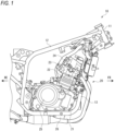
- FIG. 1 is a right side view showing an engine and a vehicle body frame according to the present embodiment.
- FIG. 2 is a right side view showing an upper portion of the engine from which a cylinder head cover is removed according to the present embodiment.
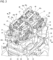
- FIG. 3 is a perspective view showing the upper portion of the engine from which the cylinder head cover is removed according to the present embodiment.
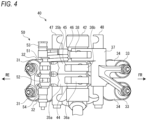
- FIG. 4 is a schematic top view showing a variable valve device according to the present embodiment.
- an arrow FR indicates a vehicle front side
- an arrow RE indicates a vehicle rear side
- an arrow L indicates a vehicle left side
- an arrow R indicates a vehicle right side.
- an oil control valve is omitted.
- a straddle-type vehicle includes various components such as an engine 20 and an electrical system mounted on a cradle type vehicle body frame 10.
- the vehicle body frame 10 includes a main tube 12 that extends rearward from an upper portion of a head pipe 11 and then is bent downward, and a down tube 13 that extends downward from a lower portion of the head pipe 11 and then is bent rearward.
- a rear end portion of the down tube 13 is joined to a lower end portion of the main tube 12 to form an installation space for the engine 20 inside the vehicle body frame 10.
- the main tube 12 supports a rear side of the engine 20, and the down tube 13 supports a front side and a lower side of the engine 20.
- the engine 20 includes a crankcase 21, a cylinder 22 provided on the crankcase 21, a cylinder head 23 provided on the cylinder 22, and a cylinder head cover 24 provided on the cylinder head 23.
- a clutch cover 25 that covers a clutch (not shown) from a side is attached to a right side surface of the crankcase 21.
- a magnet cover (not shown) that covers a magnet (not shown) from a side is attached to a left side surface of the crankcase 21.
- An oil pan 26 that stores oil is attached to a lower surface of the crankcase 21.
- the engine 20 is a four-valve two-cylinder engine, and a cam chain 27 is installed between the two cylinders.
- the cam chain 27 is wound around a cam sprocket 28, and a variable valve device 40 is installed for each of left and right cylinders across the cam sprocket 28.
- the variable valve device 40 is provided with a camshaft 41 that rotates integrally with the cam sprocket 28.
- Cam housings 42a and 42b are provided for each cylinder in the cylinder head 23 in a manner of being separated from each other in a left-right direction (a predetermined direction), and the camshaft 41 is rotatably supported by mating surfaces of the cam housings 42a and 42b and the cylinder head 23.
- each of the cams 44 to 46 is formed in a plate shape in which a cam ridge protrudes from a part of a base circle.
- a cam ridge of the high-speed cam 45 is higher than that of the low-speed cam 44 in order to make a valve lift amount of the high-speed cam 45 larger than that of the low-speed cam 44.
- An intake rocker shaft 47 and an exhaust rocker shaft 48 are supported by opposing portions of the cam housings 42a and 42b.
- the intake rocker shaft 47 and the exhaust rocker shaft 48 are positioned above the camshaft 41, and the intake rocker shaft 47 and the exhaust rocker shaft 48 extend parallel to the camshaft 41.
- An upper housing 49 is supported at both ends on upper surfaces of the cam housings 42a and 42b, and a hydraulic piston 53 and a spring pin 54 (see FIG. 4 ) are accommodated in the upper housing 49.
- An oil control valve 60 (not shown in FIG. 3 ) is installed in rear of an upper surface of the cylinder head cover 24.
- the intake rocker shaft 47 is positioned in the rear of the camshaft 41, and the exhaust rocker shaft 48 is positioned in front of the camshaft 41.
- Two types of intake rocker arms 35a and 35b are supported in a swingable manner by the intake rocker shaft 47, and an exhaust rocker arm 37 (only one is shown in FIG. 4 ) is supported in a swingable manner by the exhaust rocker shaft 48.
- the intake rocker arm 35a and the exhaust rocker arm 37 are formed in a seesaw shape having a point of effort and a point of load, and the intake rocker arm 35b is formed to be the point of effort of the intake rocker arm 35a.
- a roller 36a that is in rolling contact with the low-speed cam 44 is supported in a rotatable manner at one end of the intake rocker arm 35a, and a pair of the intake valves 31 are coupled to the other end of the intake rocker arm 35a which is bifurcated.
- a roller 36b that is in rolling contact with the high-speed cam 45 is supported in a rotatable manner at one end of the intake rocker arm 35b, and the intake valves 31 are not coupled to the other end of the intake rocker arm 35b.
- a roller 38 that is in rolling contact with the exhaust cam 46 is supported in a rotatable manner at one end of the exhaust rocker arm 37, and a pair of the exhaust valves 33 are coupled to the other end of the exhaust rocker arm 37 which is bifurcated.
- the intake rocker arms 35a and 35b are formed in a manner capable of being coupled to each other.
- the intake rocker arms 35a and 35b are not coupled. Therefore, the intake rocker arm 35a is swung by the low-speed cam 44, and the intake rocker arm 35b is swung by the high-speed cam 45. Since the pair of intake valves 31 are coupled to the intake rocker arm 35a, the pair of intake valves 31 are moved in response to rotation of the low-speed cam 44. Since the cam ridge of the low-speed cam 44 is small, valve lift amounts of the pair of intake valves 31 are small. Since the intake valves 31 are not coupled to the intake rocker arm 35b, the intake rocker arm 35b is idle in response to rotation of the high-speed cam 45.
- the intake rocker arms 35a and 35b are coupled to each other. Therefore, the intake rocker arms 35a and 35b are swung integrally by the high-speed cam 45. Since the pair of intake valves 31 are coupled to the intake rocker arm 35b via the intake rocker arm 35a, the pair of intake valves 31 are moved in response to rotation of the high-speed cam 45. Since the cam ridge of the high-speed cam 45 is large, valve lift amounts of the pair of intake valves 31 are large. In this manner, the low-speed cam 44 and the high-speed cam 45 that move the intake valves 31 are switched by switching a coupling state of the intake rocker arms 35a and 35b.
- Each variable valve device 40 is provided with a switching mechanism 50 that couples and separates the intake rocker arms 35a and 35b.
- the switching mechanism 50 is provided with a coupling pin 51 installed in a storage chamber of the intake rocker arm 35b and a return pin 52 installed in a storage chamber of the intake rocker arm 35a.
- the switching mechanism 50 is provided with the hydraulic piston 53 that is in contact with the coupling pin 51 from one side in a left-right direction, and the spring pin 54 that is in contact with the return pin 52 from the other side in the left-right direction.
- the hydraulic piston 53 can be moved forward and backward by oil pressure, and the spring pin 54 can be moved forward and backward by expansion and contraction of a spring.
- Lubrication oil is supplied from the crankcase 21 toward the variable valve device 40 through a gap between a head bolt and a bolt hole.
- the lubrication oil is pressure-fed to respective components to be lubricated through lubrication grooves around the camshaft 41.
- the upper housing 49 is formed with an injection hole opened to the atmosphere for each component to be lubricated.
- Lubrication passages extend in two directions from the lubrication groove, the lubrication oil is fed to injection holes for stem ends of the intake valves 31 and injection holes for the switching mechanism 50 through one of the lubrication passages, and the lubrication oil is fed to injection holes for stem ends of the exhaust valves 33 and injection holes for the rocker arms 35a, 35b, and 37 through the other lubrication passage.
- the one lubrication passage is provided with two injection holes for the stem ends of the exhaust valves 33 and five injection holes for the switching mechanism 50.
- the other lubrication passage is provided with two injection holes for the stem ends of the intake valves 31 and three injection holes for the rocker arms 35a, 35b, and 37. Since these injection holes are formed to have the same diameter, a total area of the injection holes opened to the atmosphere in the one lubrication passage is larger than a total area of the injection holes opened to the atmosphere in the other lubrication passage.
- the injection holes for the stem ends of the intake valves 31 and the injection holes for the switching mechanism 50 are formed in the one lubrication passage at a highest position H1 (see FIG. 2 ) in a side view.
- a passage length of the one lubrication passage is substantially the same as a passage length of the other lubrication passage, or when the passage length of the one lubrication passage is larger than the passage length of the other lubrication passage, oil pressure in the one lubrication passage is reduced.
- a supply amount of the lubrication oil from the injection holes for the stem ends of the intake valves 31 or the switching mechanism 50 is reduced, and particularly at the time of high oil temperature and low rotation, the lubrication oil is not injected from the injection holes, and these components cannot be appropriately lubricated.
- a lubrication passage in the camshaft 41 is used to increase the passage length of the other lubrication passage, thereby increasing the oil pressure in the one lubrication passage to appropriately lubricate the stem end of the intake valve 31 or the switching mechanism 50.
- FIG. 5 is a schematic diagram showing the variable valve device according to the present embodiment.
- an oil supply path 55 extends from the oil pan 26 toward the oil control valve 60.
- Oil is pumped up from the oil pan 26 by an oil pump 56 provided in an intermediate portion of the oil supply path 55, and the oil is supplied to the oil control valve 60 through an oil filter 57.
- the oil control valve 60 is formed by a valve housing 61 in which a valve spool (not shown) is accommodated, and a solenoid 62 that moves the valve spool forward and backward. When the valve spool is moved forward and backward by the solenoid 62, an oil passage in the oil control valve 60 is switched.
- An input port 63, a low-speed port 64, a high-speed port 65, and a drain port 66 are formed in the valve housing 61.
- the oil supply path 55 communicates with the input port 63, a dead end passage 67 communicates with the low-speed port 64, a switching passage 69 communicates with the high-speed port 65, and a drain passage 68 communicates with the drain port 66.
- a discharge destination of the dead end passage 67 is closed, and the switching passage 69 extends from the oil control valve 60 toward the switching mechanism 50.
- the drain passage 68 extends from the oil control valve 60 to a position above the oil pan 26, and oil is dropped from an outlet of the drain passage 68 to the oil pan 26.
- the input port 63 communicates with one of the low-speed port 64 and the high-speed port 65
- the drain port 66 communicates with the other one of the low-speed port 64 and the high-speed port 65.
- Oil is output from the oil control valve 60 to one of the dead end passage 67 and the switching passage 69, and remaining oil is discharged from the other one of the dead end passage 67 and the switching passage 69 to the oil control valve 60 (the drain passage 68). In this manner, oil pressure applied to the switching mechanism 50 is controlled by the oil control valve 60.
- the switching passage 69 is divided into an actuation passage 71 and a direct passage 74, and both the actuation passage 71 and the direct passage 74 extend from the oil control valve 60 to the hydraulic piston 53 of the switching mechanism 50.
- a part of the actuation passage 71 is formed by an oil groove 73 through which oil is allowed to pass at a predetermined rotation phase of the camshaft 41.
- the low-speed cam 44, the high-speed cam 45, and the exhaust cam 46 (not shown in FIGS. 6A and 6B ) are formed on the camshaft 41, and the oil groove 73 is formed in a part of an outer circumferential surface of the camshaft 41.
- the actuation passage 71 is divided into an upstream passage 72a and a downstream passage 72b with the oil groove 73 of the camshaft 41 interposed therebetween. By rotating the camshaft 41, communication and separation between the upstream passage 72a and the downstream passage 72b of the actuation passage 71 are alternately repeated.
- the direct passage 74 directly extends from the oil control valve 60 to the hydraulic piston 53 without passing through the oil groove 73 of the camshaft 41. After the hydraulic piston 53 is moved in response to oil supply through the actuation passage 71, the hydraulic piston 53 is maintained in a state in which the hydraulic piston 53 is pushed by oil supply through the direct passage 74.
- a predetermined rotation phase of the camshaft 41 is set from an end timing of a valve lift to a timing before the start of a subsequent valve lift.
- the coupling pin 51 is installed in a storage hole in an upper portion of the intake rocker arm 35b, and the return pin 52 is installed in a storage hole in an upper portion of the intake rocker arm 35a. A tip end of the return pin 52 is in contact with a tip end of the coupling pin 51.
- the upper housing 49 is formed with a hydraulic chamber 87 and a storage chamber 88, the hydraulic piston 53 is installed in the hydraulic chamber 87, and the spring pin 54 is installed in the storage chamber 88.
- a pressing surface of the hydraulic piston 53 is in contact with the coupling pin 51, and a pressing surface of the spring pin 54 is in contact with the return pin 52.
- a sensing arm 78 extends from the spring pin 54 to the other side.
- the switching mechanism 50 switches a coupling state of the intake rocker arms 35a and 35b by moving the coupling pin 51 by oil pressure.
- the pair of intake valves 31 are operated by the low-speed cam 44 via the intake rocker arms 35a.
- the pair of intake valves 31 are operated by the high-speed cam 45 via the intake rocker arms 35a and 35b.
- the switching mechanism 50 switches cams that move the pair of intake valves 31 by switching the coupling state of the intake rocker arms 35a and 35b by the coupling pin 51.
- the variable valve device 40 is provided with an engine control module (ECM) 75, an engine angle sensor 76, and a switching sensor 77.
- the engine angle sensor 76 detects an engine rotation speed, when the engine rotation speed is a predetermined rotation speed or more, the ECM 75 outputs a coupling command signal to the solenoid 62, and when the engine rotation speed is less than the predetermined rotation speed, the ECM 75 outputs a release command signal to the solenoid 62.
- the switching sensor 77 detects switching between the coupling state and the separation state of the intake rocker arms 35a and 35b based on movement of a tip end of the sensing arm 78. A failure of the variable valve device 40 such as a defective switching operation can be determined by comparing a command signal from the ECM 75 and a detection signal from the switching sensor 77.
- FIGS. 6A and 6B show a top view and a bottom view of the upper housing according to the present embodiment.
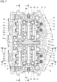
- FIG. 7 shows a top view inside the cylinder head according to the present embodiment.
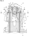
- FIG. 8 is a cross-sectional view showing the cylinder head taken along a line A-A in FIG. 7 .
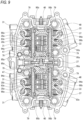
- FIG. 9 is a cross-sectional view showing the cylinder head taken along a line B-B in FIG. 8 .
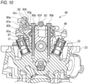
- FIG. 10 is a cross-sectional view showing the cylinder head taken along a line C-C in FIG. 7 .
- FIG. 11 is a cross-sectional view showing the cylinder head taken along a line D-D in FIG.
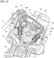
- FIG. 12 is a cross-sectional view showing the cylinder head taken along a line E-E in FIG. 7 .
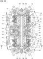
- FIG. 13 is a cross-sectional view showing the cylinder head taken along a line F-F in FIG. 8 .
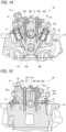
- FIG. 14 is a cross-sectional view showing the cylinder head taken along a line G-G in FIG. 13 .
- FIG. 15 is a cross-sectional view showing the cylinder head taken along a line H-H in FIG. 7 .
- FIG. 16 is a cross-sectional view showing the cylinder head taken along a line I-I in FIG. 7 .
- the upper housing 49 is formed in a ladder shape by housing fixing portions 81a and 81b extending in a front-rear direction and first to third bridge portions 82 to 84 extending in a left-right direction.
- the housing fixing portions 81a and 81b are fixed to the cam housings 42a and 42b (see FIG. 3 ).
- the first bridge portion 82 couples the housing fixing portions 81a and 81b on an intake side of the cylinder head 23.
- the second bridge portion 83 couples the housing fixing portions 81a and 81b between the intake side and an exhaust side of the cylinder head 23.
- the third bridge portion 84 couples the housing fixing portions 81a and 81b on the exhaust side of the cylinder head 23.
- the first bridge portion 82 extends along the intake rocker shaft 47 (see FIG. 3 ), and a lubrication passage 93i (see FIG. 11 ) through which lubrication oil passes is formed in the first bridge portion 82.
- a plurality of (five in the present embodiment) injection holes 94b are formed in a lower surface of the first bridge portion 82, and the plurality of injection holes 94b are positioned above contact portions with components of the switching mechanism 50.
- a pair of nozzles 91 protrude from the first bridge portion 82 toward the intake side, and injection holes 94c at tip ends of the pair of nozzles 91 are positioned above the pair of intake valves 31 (see FIG. 3 ).
- the first bridge portion 82 is coupled to the housing fixing portions 81a and 81b via coupling portions 86a and 86b.
- the hydraulic chamber 87 (see FIG. 5 ) is formed in the coupling portion 86a which is a coupling portion between the first bridge portion 82 and the housing fixing portion 81a.
- the storage chamber 88 (see FIG. 5 ) is formed in the coupling portion 86b which is a coupling portion between the first bridge portion 82 and the housing fixing portion 81b.
- the hydraulic piston 53 (see FIG. 5 ) is installed in the hydraulic chamber 87
- the spring pin 54 (see FIG. 5 ) is installed in the storage chamber 88.
- the hydraulic chamber 87 and the storage chamber 88 are formed coaxially, and parallelism between the hydraulic piston 53 and the spring pin 54 is ensured. Hydraulic oil is supplied to the hydraulic chamber 87 through a hydraulic circuit different from that of lubrication oil.
- the second bridge portion 83 extends along the camshaft 41 (see FIG. 3 ), and a lubrication passage 93s (see FIG. 16 ) is formed in the second bridge portion 83.
- a plurality of injection holes 94f are formed in a lower surface of the second bridge portion 83, and the plurality of injection holes 94f are positioned above the rocker arms 35a, 35b, and 37.
- the third bridge portion 84 extends along the exhaust rocker shaft 48 (see FIG. 3 ).
- a pair of nozzles 92 protrude from the third bridge portion 84 toward the exhaust side, and injection holes 94d at tip ends of the pair of nozzles 92 are positioned above the pair of exhaust valves 33 (see FIG. 3 ).
- An oil hole 89 is formed on the intake side of the housing fixing portion 81a, and hydraulic oil is supplied from the oil control valve 60 to the oil hole 89.
- An oil groove is formed in a lower surface of the housing fixing portion 81a, and the actuation passage 71 and the direct passage 74 through which hydraulic oil passes are formed by fixing the housing fixing portion 81a to the cam housing 42a.
- the actuation passage 71 and the direct passage 74 communicate with the hydraulic chamber 87 in which the hydraulic piston 53 is installed, and hydraulic oil is supplied from the oil control valve 60 to the hydraulic chamber 87 through the actuation passage 71 and the direct passage 74.
- the cylinder head 23 is fixed to the crankcase 21 via the cylinder 22 by a plurality of head bolts 79.
- a gap between the head bolt 79 on the exhaust side and a bolt hole serves as a lubrication passage 93a, and a lubrication passage 93b extends obliquely from the lubrication passage 93a to the camshaft 41.
- Lubrication oil is guided from the crankcase 21 to a lubrication groove 93c around the camshaft 41 through the lubrication passages 93a and 93b.
- a lubrication path 90a leading to the switching mechanism 50 and a lubrication path 90b leading to the rocker arms 35a, 35b, and 37 are divided from the lubrication groove 93c around the camshaft 41.
- the housing fixing portion 81a at the center in the left-right direction is fixed to the cylinder head 23 via the cam housing 42a by a pair of housing bolts 95a.
- a gap between the housing bolt 95a on the intake side and a bolt hole serves a lubrication passage 93d extending from the lubrication groove 93c around the camshaft 41 to the intake rocker shaft 47.
- Lubrication oil is guided from the lubrication passage 93d to a lubrication passage 93e in the intake rocker shaft 47, and the lubrication oil flows from one end to the other end of the lubrication passage 93e.
- a plurality of supply holes 94a are provided in the lubrication passage 93e in the intake rocker shaft 47, and the lubrication oil is supplied from the supply holes 94a to shaft holes of the intake rocker arms 35a and 35b.
- the supply holes 94a are not open to the atmosphere.
- the housing fixing portion 81b on an outer side in the left-right direction is fixed to the cylinder head 23 via the cam housing 42b by a pair of housing bolts 95b.
- a gap between the housing bolt 95b on the intake side and a bolt hole serves as a lubrication passage 93f extending from an end portion of the lubrication passage 93e in the intake rocker shaft 47 to the housing fixing portion 81b.
- a lubrication passage 93h extends obliquely from the lubrication passage 93g on a mating surface between the housing fixing portion 81b and the cam housing 42b to the first bridge portion 82.
- the lubrication passage 93i is formed in the first bridge portion 82, lubrication oil is guided from the lubrication passage 93h to the lubrication passage 93i, and the lubrication oil flows from the other end to one end of the lubrication passage 93i.
- the lubrication passage 93i is provided with five injection holes 94b opened to the atmosphere.
- the injection holes 94b are positioned above contact portions with the hydraulic piston 53, the coupling pin 51, the return pin 52, and the spring pin 54. Lubrication oil is injected from the injection holes 94b to the contact portions with these components.
- the pair of nozzles 91 protrude from the first bridge portion 82 to the intake side, and each nozzle 91 is formed with an injection hole 94c opened to the atmosphere.
- the injection hole 94c faces an inner wall surface of the cylinder head cover 24, and lubrication oil sprayed from the injection hole 94c to the inner wall surface is supplied to stem ends of the pair of intake valves 31 along the inner wall surface.
- a lubrication passage 93j extends from the lubrication groove 93c around the camshaft 41 toward an inner side of the camshaft 41.
- Lubrication oil is guided from the lubrication passage 93j to a lubrication passage 93k in the camshaft 41, and the lubrication oil flows to the outside in the left-right direction from the center of the lubrication passage 93k in the left-right direction.
- An outlet of the lubrication passage 93j is provided at the center in the left-right direction of the lubrication passage 93k below the cam housing 42a, and an inlet of a lubrication passage 931 is provided on an outer side in the left-right direction of the lubrication passage 93k below the cam housing 42b.
- lubrication oil is guided from the lubrication passage 931 to a lubrication groove 93m around the camshaft 41.
- a gap between the housing bolt 95b on the exhaust side and a bolt hole serves as a lubrication passage 93n extending from the lubrication groove 93m around the camshaft 41 to the exhaust rocker shaft 48.
- a pair of nozzles 92 protrude from the third bridge portion 84, and each nozzle 92 is formed with an injection hole 94d that communicates with the lubrication passage 93n and is open to the atmosphere.
- Each injection hole 94d faces a rib 96 of the cylinder head cover 24 (see FIG. 12 ), and lubrication oil sprayed from the injection hole 94d to the rib 96 is supplied to stem ends of the pair of exhaust valves 33 along the rib 96.
- lubrication oil is guided from the lubrication passage 93n to a lubrication passage 93o in the exhaust rocker shaft 48, and the lubrication oil flows from the other end to one end of the lubrication passage 93o.
- a plurality of supply holes 94e are provided in the lubrication passage 93o in the exhaust rocker shaft 48, and lubrication oil is supplied from the supply holes 94e to a shaft hole of the exhaust rocker arm 37.
- the supply holes 94e are not open to the atmosphere.
- the lubrication path 90b is folded back by the lubrication passage 93k in the camshaft 41 and the lubrication passage 93o in the exhaust rocker shaft 48.
- a gap between the exhaust side housing bolt 95a on an outlet side of the lubrication passage 93o and a bolt hole serves as a lubrication passage 93p (see FIG. 15 ).
- a lubrication passage 93r extends obliquely from the lubrication passage 93q of a mating surface between the housing fixing portion 81a and the cam housing 42a toward the second bridge portion 83.
- Lubrication oil is guided from the lubrication passage 93r to the lubrication passage 93s in the second bridge portion 83, and the lubrication oil flows from one end to the other end of the lubrication passage 93s.
- the lubrication passage 93s is provided with three injection holes 94f opened to the atmosphere.
- the injection holes 94f are positioned above the intake rocker arms 35a and 35b and the exhaust rocker arm 37. Lubrication oil is injected from the injection holes 94f to the rocker arms 35a, 35b, and 37.
- lubrication oil is pressure-fed from the lubrication groove 93c around the camshaft 41 toward the injection holes 94b to 94d and 94f.
- the lubrication path 90a enables lubrication oil to flow from the lubrication groove 93c to the injection holes 94b and 94c through the lubrication passages 94d to 93i.
- the lubrication path 90b enables lubrication oil to flow from the lubrication groove 93c, pass through the lubrication passages 93j and 93k, and pass through the lubrication groove 93m, and then flow from the lubrication groove 93m, pass through the lubrication passages 93n to 93s, and flow to the injection holes 94d and 94f.
- a passage length of the lubrication path 90b from the lubrication groove 93c to the injection hole 94f is formed to be larger than a passage length of the lubrication path 90a from the lubrication groove 93c to the injection holes 94b and 94c, so that oil pressure in the lubrication passage 93i and the injection holes 94b and 94c is increased.
- the upper housing 49 is formed with five injection holes 94b for the switching mechanism 50, two injection holes 94c for the stem ends of the intake valves 31, two injection holes 94d for the stem ends of the exhaust valves 33, and three injection holes 94f for the rocker arms 35a, 35b, and 37.
- the number of the injection holes 94b and 94c of the lubrication path 90a is larger than the number of the injection holes 94d and 94f of the lubrication path 90b.
- All of the injection holes 94b to 94d and 94f in the upper housing 49 are formed to have the same diameter, so that the injection holes 94b to 94d and 94f can be easily formed in the upper housing 49.
- Supply amounts of lubrication oil on the lubrication path 90a side and on the lubrication path 90b side are easily adjusted by adjusting a passage length.
- the injection holes 94b and 94c are provided in the same lubrication passage 93i, and the injection holes 94b and 94c are installed compactly on the intake side of the engine 20.
- the injection hole 94d is provided in the lubrication passage 93o upstream of the injection hole 94f, and a supply amount of lubrication oil from the injection hole 94f to the rocker arms 35a, 35b, and 37 is adjusted according to a position of the injection hole 94d.
- the lubrication passage 93e in the intake rocker shaft 47 is coupled in series to the lubrication passage 93i in the first bridge portion 82, and lubrication oil flows in one direction from the lubrication groove 93c toward the injection holes 94b and 94c through the lubrication passages 93e and 93i.
- the lubrication passage 93o in the exhaust rocker shaft 48 is coupled in series to the lubrication passage 93s in the second bridge portion 83, and lubrication oil flows in one direction toward the injection holes 94d and 94f through the lubrication passages 93o and 93s. Since flow directions of lubrication oil in the lubrication paths 90a and 90b are the one direction, the number of branches of passages is reduced, and an amount of the lubrication oil is easily controlled.
- the lubrication passage 93i is positioned above the lubrication passage 93e, and the lubrication passage 93s is positioned above the lubrication passage 93o. Even when the number of passages increases, the lubrication passages are made compact. As shown in FIG. 2 , the lubrication passage 93i is positioned at the highest position H1, the lubrication passage 93s is positioned at a second highest position H2, the lubrication passage 93e is positioned at a third highest position H3, and the lubrication passage 93o is positioned at a lowest position H4.
- the injection hole 94b in the lubrication passage 93i is positioned higher than the injection hole 94f in the lubrication passage 93s. Even when the switching mechanism 50 is positioned high, lubrication oil can be appropriately injected to the switching mechanism 50 by the injection of lubrication oil from the injection hole 94b.
- variable valve device 40 in the present embodiment since a passage length from the lubrication groove 93c around the camshaft 41 to the injection hole 94f for the rocker arms 35a, 35b, and 37 is longer than a passage length from the lubrication groove 93c to the injection hole 94b for the switching mechanism 50, oil pressure in a lubrication passage provided with the injection hole 94b is increased. Even when the number of components to be lubricated is increased due to the switching mechanism 50, an appropriate amount of lubrication oil is injected from the injection holes 94b to the switching mechanism 50, and an appropriate amount of lubrication oil is injected from the injection holes 94f to the rocker arms 35a, 35b, and 37. Therefore, components of the switching mechanism 50 and the rocker arms 35a, 35b, and 37 are appropriately lubricated.
- variable valve device includes a pair of intake rocker arms.
- variable valve device may include three or more intake rocker arms.
- the upper housing is formed with five injection holes for the switching mechanism and three injection holes for the rocker arms, and the injection holes are formed to have the same diameter.
- the number and sizes of the injection holes are not limited as long as a total area of the injection holes for the switching mechanism is larger than a total area of the injection holes for the rocker arms.
- the upper housing includes the first to third bridge portions.
- the upper housing may be formed to be supported at both ends on upper surfaces of a pair of cam housings.
- the type of the rocker arm is not particularly limited, and a finger follower type rocker arm may be used.
- the plurality of rocker arms may be separated from one another.
- variable valve device is not limited to being used in an engine of a straddle-type vehicle described above, and may be used in an engine of another type of vehicle.
- the straddle-type vehicle is not limited to a motorcycle, and may be any vehicle on which an engine is mounted.
- the straddle-type vehicle is not limited to a general vehicle in which a driver rides on a seat in a posture straddling the seat, and includes a scooter-type vehicle in which a driver rides on a seat without straddling the seat.
- a variable valve device is configured to change a valve operation in a cylinder head (23), the variable valve device includes a pair of cam housings (42a and 42b) separated from each other in a predetermined direction in the cylinder head, a camshaft (41) supported by the cylinder head and the pair of cam housings, a pair of rocker shafts (the intake rocker shaft 47 and the exhaust rocker shaft 48) supported by opposing portions of the pair of cam housings, a plurality of rocker arms (the intake rocker arms 35a and 35b and the exhaust rocker arm 37) supported by the pair of rocker shafts in a swingable manner, a switching mechanism (50) that couples and separates intake arms among the plurality of rocker arms, and an upper housing (49) supported at both ends on upper surfaces of the pair of cam housings, in which the upper housing is formed with a first injection hole (the injection hole 94b) for supplying lubrication oil to the switching mechanism and a second injection hole (
- the pair of rocker shafts are an intake rocker shaft and an exhaust rocker shaft
- the lubrication oil is pressure-fed to the first injection hole from the lubrication groove through an inner side of the intake rocker shaft
- the lubrication oil is pressure-fed to the second injection hole from the lubrication groove through an inner side of the camshaft and then through an inner side of the exhaust rocker shaft.
- the upper housing is formed with more first injection holes than the second injection holes. According to this configuration, by reducing the second injection holes on the rocker arm side, it is possible to increase a supply amount of lubrication oil supplied to the first injection holes for the switching mechanism having many portions to be lubricated.
- the upper housing is formed with a third injection hole (the injection hole 94c) for supplying lubrication oil to a stem end of an intake valve (31) and a fourth injection hole (the injection hole 94d) for supplying lubrication oil to a stem end of an exhaust valve (33), and the first injection hole and the third injection hole are provided in the same lubrication passage, and the fourth injection hole is provided in a lubrication passage upstream of the second injection hole.
- the first injection hole and the third injection hole can be formed compactly in the same lubrication passage, and a supply amount of lubrication oil from the second injection hole to the rocker arms can be adjusted according to a position of the fourth injection hole.
- the first injection hole and the second injection hole are formed to have the same diameter. According to this configuration, a supply amount of the lubrication oil is easily adjusted by a passage length. Further, the injection holes can be easily formed in the upper housing.
- the first injection hole is positioned higher than the second injection hole. According to this configuration, even when the switching mechanism is positioned high, the switching mechanism can be appropriately lubricated by the injection of the lubrication oil from the first injection hole.
- the pair of rocker shafts are an intake rocker shaft and an exhaust rocker shaft
- the upper housing is formed with a first lubrication passage (the lubrication passage 93i) provided with the first injection hole and a second lubrication passage (the lubrication passage 93s) provided with the second injection hole
- the intake rocker shaft is formed with a third lubrication passage (the lubrication passage 93e) that is coupled in series to the first lubrication passage
- the exhaust rocker shaft is formed with a fourth lubrication passage (the lubrication passage 93o) that is coupled in series to the second lubrication passage
- the first lubrication passage is positioned above the third lubrication passage
- the second lubrication passage is positioned above the fourth lubrication passage.
- the lubrication passage can be made compact even when the number of passages increases. Since the first lubrication passage and the third lubrication passage are coupled in series and the second lubrication passage and the fourth lubrication passage are coupled in series, lubrication oil flows in one direction from the lubrication groove toward a first supply hole and a second supply hole, and an amount of the lubrication oil is easily controlled.
- the technique according to the present invention is not limited to the embodiment described above, and may be variously changed, replaced, or modified without departing from the gist of the technical concept. Further, the present invention may be implemented by other methods as long as the technical concept can be implemented by the methods through advance of the technique or other derivative techniques. Therefore, the claims cover all embodiments that may fall within the scope of the technical concept.
Landscapes
- Engineering & Computer Science (AREA)
- Mechanical Engineering (AREA)
- General Engineering & Computer Science (AREA)
- Chemical & Material Sciences (AREA)
- Combustion & Propulsion (AREA)
- Valve-Gear Or Valve Arrangements (AREA)
- Valve Device For Special Equipments (AREA)
- Lubrication Of Internal Combustion Engines (AREA)
- Cylinder Crankcases Of Internal Combustion Engines (AREA)
Abstract
The variable valve device (40) includes a pair of cam housings (42a, 42b) separated from each other in a predetermined direction, a pair of rocker shafts (47, 48) supported by the pair of cam housings, a plurality of rocker arms (35a, 35b, 37) supported by the pair of rocker shafts in a swingable manner, a switching mechanism (50) that couples and separates intake arms, and an upper housing (49) on the pair of cam housings. The upper housing is formed with a first injection hole for supplying lubrication oil to the switching mechanism and a second injection hole for supplying lubrication oil to the rocker arms. A passage length from a lubrication groove around a camshaft (41) to the second injection hole is larger than a passage length from the lubrication groove to the first injection hole.
Description
- The present invention relates to a variable valve device.
- In the related art, there is known a variable valve device in which a plurality of rocker arms are coupled to one another to switch a valve operation (for example, see Patent Literature 1). In the variable valve device described in Patent Literature 1, a pair of rocker arms are installed adjacent to each other, and a coupling pin is installed in a pin hole of one rocker arm. A part of the coupling pin is pushed into a pin hole of the other rocker arm to couple the pair of rocker arms, and the part of the coupling pin is pulled out of the pin hole of the other rocker arm to separate the pair of rocker arms. A valve lift cam is switched by switching coupling and separation of the pair of rocker arms.
- The variable valve device described above also requires lubrication, but a lubrication passage is complicated when the number of components to be lubricated increases. Due to the increase in the number of components to be lubricated and the complication of the lubrication passage, it may be difficult to appropriately supply lubrication oil to each component, and durability may be lowered.
- The present invention is made in view of the above circumstance, and an object of the present invention is to provide a variable valve device capable of improving lubricity of each component by appropriately supplying lubrication oil to each component.
- In order to solve the above problem, a variable valve device according to one aspect of the present invention is a variable valve device configured to change a valve operation in a cylinder head. The variable valve device includes a pair of cam housings separated from each other in a predetermined direction in the cylinder head, a camshaft supported by the cylinder head and the pair of cam housings, a pair of rocker shafts supported by opposing portions of the pair of cam housings, a plurality of rocker arms supported by the pair of rocker shafts in a swingable manner, a switching mechanism that couples and separates intake arms among the plurality of rocker arms, and an upper housing supported at both ends on upper surfaces of the pair of cam housings, in which the upper housing is formed with a first injection hole for supplying lubrication oil to the switching mechanism and a second injection hole for supplying lubrication oil to the plurality of rocker arms, and the lubrication oil is pressure-fed from a lubrication groove around the camshaft to the first injection hole and the second injection hole, and a passage length from the lubrication groove to the second injection hole is larger than a passage length from the lubrication groove to the first injection hole.
- According to the variable valve device in the one aspect of the present invention, since the passage length from the lubrication groove around the camshaft to the second injection hole is larger than the passage length from the lubrication groove to the first injection hole, oil pressure in a lubrication passage that communicates with the first injection hole on the switching mechanism side is increased. Even when the number of components to be lubricated is increased due to the switching mechanism, an appropriate amount of lubrication oil is supplied from the first injection hole to the switching mechanism, and an appropriate amount of lubrication oil is supplied from the second injection hole to the plurality of rocker arms. Therefore, components of the switching mechanism and the rocker arms are appropriately lubricated.
-
-
FIG. 1 is a right side view showing an engine and a vehicle body frame according to an embodiment. -
FIG. 2 is a right side view showing an upper portion of the engine from which a cylinder head cover is removed according to the present embodiment. -
FIG. 3 is a perspective view showing the upper portion of the engine from which the cylinder head cover is removed according to the present embodiment. -
FIG. 4 is a schematic top view showing a variable valve device according to the present embodiment. -
FIG. 5 is a schematic view showing the variable valve device according to the present embodiment. -
FIGS. 6A and 6B show a top view and a bottom view of an upper housing according to the present embodiment. -
FIG. 7 shows a top view inside a cylinder head according to the present embodiment. -
FIG. 8 is a cross-sectional view showing the cylinder head taken along a line A-A inFIG. 7 . -
FIG. 9 is a cross-sectional view showing the cylinder head taken along a line B-B inFIG. 8 . -
FIG. 10 is a cross-sectional view showing the cylinder head taken along a line C-C inFIG. 7 . -
FIG. 11 is a cross-sectional view showing the cylinder head taken along a line D-D inFIG. 7 . -
FIG. 12 is a cross-sectional view showing the cylinder head taken along a line E-E inFIG. 7 . -
FIG. 13 is a cross-sectional view showing the cylinder head taken along a line F-F inFIG. 8 . -
FIG. 14 is a cross-sectional view showing the cylinder head taken along a line G-G inFIG. 13 . -
FIG. 15 is a cross-sectional view showing the cylinder head taken along a line H-H inFIG. 7 . -
FIG. 16 is a cross-sectional view showing the cylinder head taken along a line I-I inFIG. 7 . - A variable valve device according to one aspect of the present invention changes a valve operation in a cylinder head. In the cylinder head, a pair of cam housings are separated from each other in a predetermined direction, and a camshaft is supported by the cylinder head and the pair of cam housings. An upper housing is supported at both ends on upper surfaces of the pair of cam housings. A rocker shaft is supported by opposing portions of the pair of cam housings, and a plurality of rocker arms are supported in a swingable manner by the rocker shaft. Among the plurality of rocker arms, intake arms are coupled and separated by a switching mechanism. The upper housing is formed with a first injection hole for supplying lubrication oil to the switching mechanism and a second injection hole for supplying lubrication oil to the plurality of rocker arms. The lubrication oil is pressure-fed from a lubrication groove around the camshaft to the first injection hole and the second injection hole. A passage length from the lubrication groove around the camshaft to the second injection hole is larger than a passage length from the lubrication groove to the first injection hole, and oil pressure in a lubrication passage that communicates with the first injection hole on the switching mechanism side is increased. Even when the number of components to be lubricated is increased due to the switching mechanism, an appropriate amount of lubrication oil is supplied from the first injection hole to the switching mechanism, and an appropriate amount of lubrication oil is supplied from the second injection hole to the plurality of rocker arms. Therefore, components of the switching mechanism and the rocker arms are appropriately lubricated.
- Hereinafter, an embodiment will be described in detail with reference to the accompanying drawings.
FIG. 1 is a right side view showing an engine and a vehicle body frame according to the present embodiment.FIG. 2 is a right side view showing an upper portion of the engine from which a cylinder head cover is removed according to the present embodiment.FIG. 3 is a perspective view showing the upper portion of the engine from which the cylinder head cover is removed according to the present embodiment.FIG. 4 is a schematic top view showing a variable valve device according to the present embodiment. In the following drawings, an arrow FR indicates a vehicle front side, an arrow RE indicates a vehicle rear side, an arrow L indicates a vehicle left side, and an arrow R indicates a vehicle right side. InFIG. 3 , an oil control valve is omitted. - As shown in
FIG. 1 , a straddle-type vehicle includes various components such as anengine 20 and an electrical system mounted on a cradle typevehicle body frame 10. Thevehicle body frame 10 includes amain tube 12 that extends rearward from an upper portion of ahead pipe 11 and then is bent downward, and adown tube 13 that extends downward from a lower portion of thehead pipe 11 and then is bent rearward. A rear end portion of thedown tube 13 is joined to a lower end portion of themain tube 12 to form an installation space for theengine 20 inside thevehicle body frame 10. Themain tube 12 supports a rear side of theengine 20, and thedown tube 13 supports a front side and a lower side of theengine 20. - The
engine 20 includes acrankcase 21, acylinder 22 provided on thecrankcase 21, acylinder head 23 provided on thecylinder 22, and acylinder head cover 24 provided on thecylinder head 23. Aclutch cover 25 that covers a clutch (not shown) from a side is attached to a right side surface of thecrankcase 21. A magnet cover (not shown) that covers a magnet (not shown) from a side is attached to a left side surface of thecrankcase 21. Anoil pan 26 that stores oil is attached to a lower surface of thecrankcase 21. - As shown in
FIGS. 2 and3 , theengine 20 is a four-valve two-cylinder engine, and acam chain 27 is installed between the two cylinders. Thecam chain 27 is wound around acam sprocket 28, and avariable valve device 40 is installed for each of left and right cylinders across thecam sprocket 28. Thevariable valve device 40 is provided with acamshaft 41 that rotates integrally with thecam sprocket 28.Cam housings cylinder head 23 in a manner of being separated from each other in a left-right direction (a predetermined direction), and thecamshaft 41 is rotatably supported by mating surfaces of thecam housings cylinder head 23. - In the
cylinder head 23, fourintake valves 31 are installed in rear of thecamshaft 41, and fourexhaust valves 33 are installed in front of thecamshaft 41. Theintake valve 31 is pressed in a valve closing direction by avalve spring 32, and theexhaust valve 33 is pressed in a valve closing direction by avalve spring 34. A low-speed cam 44, a high-speed cam 45, and an exhaust cam 46 (seeFIG. 4 ) are formed on an outer circumferential surface of thecamshaft 41. Each of thecams 44 to 46 is formed in a plate shape in which a cam ridge protrudes from a part of a base circle. A cam ridge of the high-speed cam 45 is higher than that of the low-speed cam 44 in order to make a valve lift amount of the high-speed cam 45 larger than that of the low-speed cam 44. - An
intake rocker shaft 47 and anexhaust rocker shaft 48 are supported by opposing portions of thecam housings intake rocker shaft 47 and theexhaust rocker shaft 48 are positioned above thecamshaft 41, and theintake rocker shaft 47 and theexhaust rocker shaft 48 extend parallel to thecamshaft 41. Anupper housing 49 is supported at both ends on upper surfaces of thecam housings hydraulic piston 53 and a spring pin 54 (seeFIG. 4 ) are accommodated in theupper housing 49. An oil control valve 60 (not shown inFIG. 3 ) is installed in rear of an upper surface of thecylinder head cover 24. - As shown in
FIG. 4 , theintake rocker shaft 47 is positioned in the rear of thecamshaft 41, and theexhaust rocker shaft 48 is positioned in front of thecamshaft 41. Two types ofintake rocker arms FIG. 4 ) are supported in a swingable manner by theintake rocker shaft 47, and an exhaust rocker arm 37 (only one is shown inFIG. 4 ) is supported in a swingable manner by theexhaust rocker shaft 48. Theintake rocker arm 35a and theexhaust rocker arm 37 are formed in a seesaw shape having a point of effort and a point of load, and theintake rocker arm 35b is formed to be the point of effort of theintake rocker arm 35a. - A
roller 36a that is in rolling contact with the low-speed cam 44 is supported in a rotatable manner at one end of theintake rocker arm 35a, and a pair of theintake valves 31 are coupled to the other end of theintake rocker arm 35a which is bifurcated. Aroller 36b that is in rolling contact with the high-speed cam 45 is supported in a rotatable manner at one end of theintake rocker arm 35b, and theintake valves 31 are not coupled to the other end of theintake rocker arm 35b. Aroller 38 that is in rolling contact with theexhaust cam 46 is supported in a rotatable manner at one end of theexhaust rocker arm 37, and a pair of theexhaust valves 33 are coupled to the other end of theexhaust rocker arm 37 which is bifurcated. Theintake rocker arms - When an engine rotates at a low-speed and a medium speed, the
intake rocker arms intake rocker arm 35a is swung by the low-speed cam 44, and theintake rocker arm 35b is swung by the high-speed cam 45. Since the pair ofintake valves 31 are coupled to theintake rocker arm 35a, the pair ofintake valves 31 are moved in response to rotation of the low-speed cam 44. Since the cam ridge of the low-speed cam 44 is small, valve lift amounts of the pair ofintake valves 31 are small. Since theintake valves 31 are not coupled to theintake rocker arm 35b, theintake rocker arm 35b is idle in response to rotation of the high-speed cam 45. - When the engine rotates at a high-speed, the
intake rocker arms intake rocker arms speed cam 45. Since the pair ofintake valves 31 are coupled to theintake rocker arm 35b via theintake rocker arm 35a, the pair ofintake valves 31 are moved in response to rotation of the high-speed cam 45. Since the cam ridge of the high-speed cam 45 is large, valve lift amounts of the pair ofintake valves 31 are large. In this manner, the low-speed cam 44 and the high-speed cam 45 that move theintake valves 31 are switched by switching a coupling state of theintake rocker arms - Each
variable valve device 40 is provided with aswitching mechanism 50 that couples and separates theintake rocker arms switching mechanism 50 is provided with acoupling pin 51 installed in a storage chamber of theintake rocker arm 35b and areturn pin 52 installed in a storage chamber of theintake rocker arm 35a. Theswitching mechanism 50 is provided with thehydraulic piston 53 that is in contact with thecoupling pin 51 from one side in a left-right direction, and thespring pin 54 that is in contact with thereturn pin 52 from the other side in the left-right direction. Thehydraulic piston 53 can be moved forward and backward by oil pressure, and thespring pin 54 can be moved forward and backward by expansion and contraction of a spring. - When hydraulic oil is supplied to the
hydraulic piston 53, thehydraulic piston 53 is moved forward against a spring force of thespring pin 54. As thehydraulic piston 53 is moved forward, thereturn pin 52 is pushed by thecoupling pin 51, and a part of thecoupling pin 51 enters the storage chamber of theintake rocker arm 35a from the storage chamber of theintake rocker arm 35b to couple theintake rocker arms hydraulic piston 53, thehydraulic piston 53 is moved backward by the spring force of thespring pin 54. As thehydraulic piston 53 is moved backward, thecoupling pin 51 is pushed back by thereturn pin 52, and a part of thecoupling pin 51 is pulled out of the storage chamber of theintake rocker arm 35a to separate theintake rocker arms - Lubrication oil is supplied from the
crankcase 21 toward thevariable valve device 40 through a gap between a head bolt and a bolt hole. In thevariable valve device 40, the lubrication oil is pressure-fed to respective components to be lubricated through lubrication grooves around thecamshaft 41. Theupper housing 49 is formed with an injection hole opened to the atmosphere for each component to be lubricated. Lubrication passages extend in two directions from the lubrication groove, the lubrication oil is fed to injection holes for stem ends of theintake valves 31 and injection holes for theswitching mechanism 50 through one of the lubrication passages, and the lubrication oil is fed to injection holes for stem ends of theexhaust valves 33 and injection holes for therocker arms - At this time, the one lubrication passage is provided with two injection holes for the stem ends of the
exhaust valves 33 and five injection holes for theswitching mechanism 50. The other lubrication passage is provided with two injection holes for the stem ends of theintake valves 31 and three injection holes for therocker arms intake valves 31 and the injection holes for theswitching mechanism 50 are formed in the one lubrication passage at a highest position H1 (seeFIG. 2 ) in a side view. - Therefore, when a passage length of the one lubrication passage is substantially the same as a passage length of the other lubrication passage, or when the passage length of the one lubrication passage is larger than the passage length of the other lubrication passage, oil pressure in the one lubrication passage is reduced. A supply amount of the lubrication oil from the injection holes for the stem ends of the
intake valves 31 or theswitching mechanism 50 is reduced, and particularly at the time of high oil temperature and low rotation, the lubrication oil is not injected from the injection holes, and these components cannot be appropriately lubricated. In the present embodiment, a lubrication passage in thecamshaft 41 is used to increase the passage length of the other lubrication passage, thereby increasing the oil pressure in the one lubrication passage to appropriately lubricate the stem end of theintake valve 31 or theswitching mechanism 50. - The variable valve device will be described with reference to
FIG. 5. FIG. 5 is a schematic diagram showing the variable valve device according to the present embodiment. - As shown in
FIG. 5 , in thevariable valve device 40, anoil supply path 55 extends from theoil pan 26 toward theoil control valve 60. Oil is pumped up from theoil pan 26 by anoil pump 56 provided in an intermediate portion of theoil supply path 55, and the oil is supplied to theoil control valve 60 through anoil filter 57. Theoil control valve 60 is formed by avalve housing 61 in which a valve spool (not shown) is accommodated, and asolenoid 62 that moves the valve spool forward and backward. When the valve spool is moved forward and backward by thesolenoid 62, an oil passage in theoil control valve 60 is switched. - An
input port 63, a low-speed port 64, a high-speed port 65, and adrain port 66 are formed in thevalve housing 61. Theoil supply path 55 communicates with theinput port 63, adead end passage 67 communicates with the low-speed port 64, aswitching passage 69 communicates with the high-speed port 65, and adrain passage 68 communicates with thedrain port 66. A discharge destination of thedead end passage 67 is closed, and theswitching passage 69 extends from theoil control valve 60 toward theswitching mechanism 50. Thedrain passage 68 extends from theoil control valve 60 to a position above theoil pan 26, and oil is dropped from an outlet of thedrain passage 68 to theoil pan 26. - By moving the valve spool of the
oil control valve 60, theinput port 63 communicates with one of the low-speed port 64 and the high-speed port 65, and thedrain port 66 communicates with the other one of the low-speed port 64 and the high-speed port 65. Oil is output from theoil control valve 60 to one of thedead end passage 67 and theswitching passage 69, and remaining oil is discharged from the other one of thedead end passage 67 and theswitching passage 69 to the oil control valve 60 (the drain passage 68). In this manner, oil pressure applied to theswitching mechanism 50 is controlled by theoil control valve 60. - The switching
passage 69 is divided into anactuation passage 71 and adirect passage 74, and both theactuation passage 71 and thedirect passage 74 extend from theoil control valve 60 to thehydraulic piston 53 of theswitching mechanism 50. A part of theactuation passage 71 is formed by anoil groove 73 through which oil is allowed to pass at a predetermined rotation phase of thecamshaft 41. As described above, the low-speed cam 44, the high-speed cam 45, and the exhaust cam 46 (not shown inFIGS. 6A and 6B ) are formed on thecamshaft 41, and theoil groove 73 is formed in a part of an outer circumferential surface of thecamshaft 41. - The
actuation passage 71 is divided into anupstream passage 72a and adownstream passage 72b with theoil groove 73 of thecamshaft 41 interposed therebetween. By rotating thecamshaft 41, communication and separation between theupstream passage 72a and thedownstream passage 72b of theactuation passage 71 are alternately repeated. Thedirect passage 74 directly extends from theoil control valve 60 to thehydraulic piston 53 without passing through theoil groove 73 of thecamshaft 41. After thehydraulic piston 53 is moved in response to oil supply through theactuation passage 71, thehydraulic piston 53 is maintained in a state in which thehydraulic piston 53 is pushed by oil supply through thedirect passage 74. A predetermined rotation phase of thecamshaft 41 is set from an end timing of a valve lift to a timing before the start of a subsequent valve lift. - The
coupling pin 51 is installed in a storage hole in an upper portion of theintake rocker arm 35b, and thereturn pin 52 is installed in a storage hole in an upper portion of theintake rocker arm 35a. A tip end of thereturn pin 52 is in contact with a tip end of thecoupling pin 51. Theupper housing 49 is formed with ahydraulic chamber 87 and astorage chamber 88, thehydraulic piston 53 is installed in thehydraulic chamber 87, and thespring pin 54 is installed in thestorage chamber 88. A pressing surface of thehydraulic piston 53 is in contact with thecoupling pin 51, and a pressing surface of thespring pin 54 is in contact with thereturn pin 52. Asensing arm 78 extends from thespring pin 54 to the other side. - The
switching mechanism 50 switches a coupling state of theintake rocker arms coupling pin 51 by oil pressure. As described above, in a separation state of theintake rocker arms intake valves 31 are operated by the low-speed cam 44 via theintake rocker arms 35a. In a coupling state of theintake rocker arms intake valves 31 are operated by the high-speed cam 45 via theintake rocker arms switching mechanism 50 switches cams that move the pair ofintake valves 31 by switching the coupling state of theintake rocker arms coupling pin 51. - The
variable valve device 40 is provided with an engine control module (ECM) 75, anengine angle sensor 76, and a switchingsensor 77. Theengine angle sensor 76 detects an engine rotation speed, when the engine rotation speed is a predetermined rotation speed or more, theECM 75 outputs a coupling command signal to thesolenoid 62, and when the engine rotation speed is less than the predetermined rotation speed, theECM 75 outputs a release command signal to thesolenoid 62. The switchingsensor 77 detects switching between the coupling state and the separation state of theintake rocker arms sensing arm 78. A failure of thevariable valve device 40 such as a defective switching operation can be determined by comparing a command signal from theECM 75 and a detection signal from the switchingsensor 77. - Hereinafter, lubrication and hydraulic oil passages will be described with reference to
FIGS. 6A to 16 .FIGS. 6A and 6B show a top view and a bottom view of the upper housing according to the present embodiment.FIG. 7 shows a top view inside the cylinder head according to the present embodiment.FIG. 8 is a cross-sectional view showing the cylinder head taken along a line A-A inFIG. 7 .FIG. 9 is a cross-sectional view showing the cylinder head taken along a line B-B inFIG. 8 .FIG. 10 is a cross-sectional view showing the cylinder head taken along a line C-C inFIG. 7 .FIG. 11 is a cross-sectional view showing the cylinder head taken along a line D-D inFIG. 7 .FIG. 12 is a cross-sectional view showing the cylinder head taken along a line E-E inFIG. 7 .FIG. 13 is a cross-sectional view showing the cylinder head taken along a line F-F inFIG. 8 .FIG. 14 is a cross-sectional view showing the cylinder head taken along a line G-G inFIG. 13 .FIG. 15 is a cross-sectional view showing the cylinder head taken along a line H-H inFIG. 7 .FIG. 16 is a cross-sectional view showing the cylinder head taken along a line I-I inFIG. 7 . - As shown in
FIG. 6A and FIG. 6B , theupper housing 49 is formed in a ladder shape byhousing fixing portions third bridge portions 82 to 84 extending in a left-right direction. Thehousing fixing portions cam housings FIG. 3 ). Thefirst bridge portion 82 couples thehousing fixing portions cylinder head 23. Thesecond bridge portion 83 couples thehousing fixing portions cylinder head 23. Thethird bridge portion 84 couples thehousing fixing portions cylinder head 23. - The
first bridge portion 82 extends along the intake rocker shaft 47 (seeFIG. 3 ), and alubrication passage 93i (seeFIG. 11 ) through which lubrication oil passes is formed in thefirst bridge portion 82. A plurality of (five in the present embodiment) injection holes 94b are formed in a lower surface of thefirst bridge portion 82, and the plurality ofinjection holes 94b are positioned above contact portions with components of theswitching mechanism 50. A pair ofnozzles 91 protrude from thefirst bridge portion 82 toward the intake side, andinjection holes 94c at tip ends of the pair ofnozzles 91 are positioned above the pair of intake valves 31 (seeFIG. 3 ). Thefirst bridge portion 82 is coupled to thehousing fixing portions coupling portions - The hydraulic chamber 87 (see
FIG. 5 ) is formed in thecoupling portion 86a which is a coupling portion between thefirst bridge portion 82 and thehousing fixing portion 81a. The storage chamber 88 (seeFIG. 5 ) is formed in thecoupling portion 86b which is a coupling portion between thefirst bridge portion 82 and thehousing fixing portion 81b. The hydraulic piston 53 (seeFIG. 5 ) is installed in thehydraulic chamber 87, and the spring pin 54 (seeFIG. 5 ) is installed in thestorage chamber 88. Thehydraulic chamber 87 and thestorage chamber 88 are formed coaxially, and parallelism between thehydraulic piston 53 and thespring pin 54 is ensured. Hydraulic oil is supplied to thehydraulic chamber 87 through a hydraulic circuit different from that of lubrication oil. - The
second bridge portion 83 extends along the camshaft 41 (seeFIG. 3 ), and alubrication passage 93s (seeFIG. 16 ) is formed in thesecond bridge portion 83. A plurality ofinjection holes 94f are formed in a lower surface of thesecond bridge portion 83, and the plurality ofinjection holes 94f are positioned above therocker arms third bridge portion 84 extends along the exhaust rocker shaft 48 (seeFIG. 3 ). A pair ofnozzles 92 protrude from thethird bridge portion 84 toward the exhaust side, andinjection holes 94d at tip ends of the pair ofnozzles 92 are positioned above the pair of exhaust valves 33 (seeFIG. 3 ). - An
oil hole 89 is formed on the intake side of thehousing fixing portion 81a, and hydraulic oil is supplied from theoil control valve 60 to theoil hole 89. An oil groove is formed in a lower surface of thehousing fixing portion 81a, and theactuation passage 71 and thedirect passage 74 through which hydraulic oil passes are formed by fixing thehousing fixing portion 81a to thecam housing 42a. Theactuation passage 71 and thedirect passage 74 communicate with thehydraulic chamber 87 in which thehydraulic piston 53 is installed, and hydraulic oil is supplied from theoil control valve 60 to thehydraulic chamber 87 through theactuation passage 71 and thedirect passage 74. - An oil groove is formed in a lower surface of the
housing fixing portion 81a, and alubrication passage 93q is formed by fixing thehousing fixing portion 81a to thecam housing 42a. Lubrication oil is fed from thelubrication passage 93q to thelubrication passage 93s of thesecond bridge portion 83. An oil groove is formed in a lower surface of thehousing fixing portion 81b, and alubrication passage 93g is formed by fixing thehousing fixing portion 81b to thecam housing 42b. Lubrication oil is fed from thelubrication passage 93g to thelubrication passage 93i of thefirst bridge portion 82. In this manner, a hydraulic circuit for lubrication oil and hydraulic oil is formed in theupper housing 49. - As shown in
FIGS. 7 to 9 , thecylinder head 23 is fixed to thecrankcase 21 via thecylinder 22 by a plurality ofhead bolts 79. A gap between thehead bolt 79 on the exhaust side and a bolt hole serves as alubrication passage 93a, and alubrication passage 93b extends obliquely from thelubrication passage 93a to thecamshaft 41. Lubrication oil is guided from thecrankcase 21 to alubrication groove 93c around thecamshaft 41 through thelubrication passages lubrication path 90a leading to theswitching mechanism 50 and alubrication path 90b leading to therocker arms lubrication groove 93c around thecamshaft 41. - First, the
lubrication path 90a will be described. Thehousing fixing portion 81a at the center in the left-right direction is fixed to thecylinder head 23 via thecam housing 42a by a pair ofhousing bolts 95a. A gap between thehousing bolt 95a on the intake side and a bolt hole serves alubrication passage 93d extending from thelubrication groove 93c around thecamshaft 41 to theintake rocker shaft 47. Lubrication oil is guided from thelubrication passage 93d to alubrication passage 93e in theintake rocker shaft 47, and the lubrication oil flows from one end to the other end of thelubrication passage 93e. A plurality ofsupply holes 94a are provided in thelubrication passage 93e in theintake rocker shaft 47, and the lubrication oil is supplied from thesupply holes 94a to shaft holes of theintake rocker arms - As shown in
FIGS. 7 and10 , thehousing fixing portion 81b on an outer side in the left-right direction is fixed to thecylinder head 23 via thecam housing 42b by a pair ofhousing bolts 95b. A gap between thehousing bolt 95b on the intake side and a bolt hole serves as alubrication passage 93f extending from an end portion of thelubrication passage 93e in theintake rocker shaft 47 to thehousing fixing portion 81b. Alubrication passage 93h extends obliquely from thelubrication passage 93g on a mating surface between thehousing fixing portion 81b and thecam housing 42b to thefirst bridge portion 82. Thelubrication passage 93i is formed in thefirst bridge portion 82, lubrication oil is guided from thelubrication passage 93h to thelubrication passage 93i, and the lubrication oil flows from the other end to one end of thelubrication passage 93i. - As shown in
FIGS. 7 and11 , thelubrication passage 93i is provided with fiveinjection holes 94b opened to the atmosphere. The injection holes 94b are positioned above contact portions with thehydraulic piston 53, thecoupling pin 51, thereturn pin 52, and thespring pin 54. Lubrication oil is injected from the injection holes 94b to the contact portions with these components. As shown inFIGS. 7 and12 , the pair ofnozzles 91 protrude from thefirst bridge portion 82 to the intake side, and eachnozzle 91 is formed with aninjection hole 94c opened to the atmosphere. Theinjection hole 94c faces an inner wall surface of thecylinder head cover 24, and lubrication oil sprayed from theinjection hole 94c to the inner wall surface is supplied to stem ends of the pair ofintake valves 31 along the inner wall surface. - Next, the
lubrication path 90b will be described. As shown inFIGS. 8 and13 , below thecam housing 42a at the center in the left-right direction, alubrication passage 93j extends from thelubrication groove 93c around thecamshaft 41 toward an inner side of thecamshaft 41. Lubrication oil is guided from thelubrication passage 93j to alubrication passage 93k in thecamshaft 41, and the lubrication oil flows to the outside in the left-right direction from the center of thelubrication passage 93k in the left-right direction. An outlet of thelubrication passage 93j is provided at the center in the left-right direction of thelubrication passage 93k below thecam housing 42a, and an inlet of alubrication passage 931 is provided on an outer side in the left-right direction of thelubrication passage 93k below thecam housing 42b. - As shown in
FIGS. 13 and14 , below thecam housing 42b on an outer side in the left-right direction, lubrication oil is guided from thelubrication passage 931 to alubrication groove 93m around thecamshaft 41. A gap between thehousing bolt 95b on the exhaust side and a bolt hole serves as alubrication passage 93n extending from thelubrication groove 93m around thecamshaft 41 to theexhaust rocker shaft 48. A pair of nozzles 92 (see particularlyFIG. 7 ) protrude from thethird bridge portion 84, and eachnozzle 92 is formed with aninjection hole 94d that communicates with thelubrication passage 93n and is open to the atmosphere. Eachinjection hole 94d faces arib 96 of the cylinder head cover 24 (seeFIG. 12 ), and lubrication oil sprayed from theinjection hole 94d to therib 96 is supplied to stem ends of the pair ofexhaust valves 33 along therib 96. - As shown in
FIGS. 9 and14 , lubrication oil is guided from thelubrication passage 93n to a lubrication passage 93o in theexhaust rocker shaft 48, and the lubrication oil flows from the other end to one end of the lubrication passage 93o. A plurality ofsupply holes 94e are provided in the lubrication passage 93o in theexhaust rocker shaft 48, and lubrication oil is supplied from thesupply holes 94e to a shaft hole of theexhaust rocker arm 37. The supply holes 94e are not open to the atmosphere. In this manner, thelubrication path 90b is folded back by thelubrication passage 93k in thecamshaft 41 and the lubrication passage 93o in theexhaust rocker shaft 48. A gap between the exhaustside housing bolt 95a on an outlet side of the lubrication passage 93o and a bolt hole serves as alubrication passage 93p (seeFIG. 15 ). - As shown in
FIGS. 15 and16 , alubrication passage 93r extends obliquely from thelubrication passage 93q of a mating surface between thehousing fixing portion 81a and thecam housing 42a toward thesecond bridge portion 83. Lubrication oil is guided from thelubrication passage 93r to thelubrication passage 93s in thesecond bridge portion 83, and the lubrication oil flows from one end to the other end of thelubrication passage 93s. Thelubrication passage 93s is provided with threeinjection holes 94f opened to the atmosphere. The injection holes 94f are positioned above theintake rocker arms exhaust rocker arm 37. Lubrication oil is injected from the injection holes 94f to therocker arms - In this manner, lubrication oil is pressure-fed from the
lubrication groove 93c around thecamshaft 41 toward the injection holes 94b to 94d and 94f. Thelubrication path 90a enables lubrication oil to flow from thelubrication groove 93c to the injection holes 94b and 94c through thelubrication passages 94d to 93i. Thelubrication path 90b enables lubrication oil to flow from thelubrication groove 93c, pass through thelubrication passages lubrication groove 93m, and then flow from thelubrication groove 93m, pass through thelubrication passages 93n to 93s, and flow to the injection holes 94d and 94f. A passage length of thelubrication path 90b from thelubrication groove 93c to theinjection hole 94f is formed to be larger than a passage length of thelubrication path 90a from thelubrication groove 93c to the injection holes 94b and 94c, so that oil pressure in thelubrication passage 93i and the injection holes 94b and 94c is increased. - As described above, the
upper housing 49 is formed with fiveinjection holes 94b for theswitching mechanism 50, twoinjection holes 94c for the stem ends of theintake valves 31, twoinjection holes 94d for the stem ends of theexhaust valves 33, and threeinjection holes 94f for therocker arms lubrication path 90a is larger than the number of the injection holes 94d and 94f of thelubrication path 90b. Since the number of the injection holes 94d and 94f on thelubrication path 90b side is reduced, it is possible to increase a supply amount of lubrication oil to the injection holes 94b for theswitching mechanism 50 having many portions to be lubricated on thelubrication path 90a side. - All of the injection holes 94b to 94d and 94f in the
upper housing 49 are formed to have the same diameter, so that the injection holes 94b to 94d and 94f can be easily formed in theupper housing 49. Supply amounts of lubrication oil on thelubrication path 90a side and on thelubrication path 90b side are easily adjusted by adjusting a passage length. The injection holes 94b and 94c are provided in thesame lubrication passage 93i, and the injection holes 94b and 94c are installed compactly on the intake side of theengine 20. Theinjection hole 94d is provided in the lubrication passage 93o upstream of theinjection hole 94f, and a supply amount of lubrication oil from theinjection hole 94f to therocker arms injection hole 94d. - The
lubrication passage 93e in theintake rocker shaft 47 is coupled in series to thelubrication passage 93i in thefirst bridge portion 82, and lubrication oil flows in one direction from thelubrication groove 93c toward the injection holes 94b and 94c through thelubrication passages exhaust rocker shaft 48 is coupled in series to thelubrication passage 93s in thesecond bridge portion 83, and lubrication oil flows in one direction toward the injection holes 94d and 94f through thelubrication passages 93o and 93s. Since flow directions of lubrication oil in thelubrication paths - The
lubrication passage 93i is positioned above thelubrication passage 93e, and thelubrication passage 93s is positioned above the lubrication passage 93o. Even when the number of passages increases, the lubrication passages are made compact. As shown inFIG. 2 , thelubrication passage 93i is positioned at the highest position H1, thelubrication passage 93s is positioned at a second highest position H2, thelubrication passage 93e is positioned at a third highest position H3, and the lubrication passage 93o is positioned at a lowest position H4. Theinjection hole 94b in thelubrication passage 93i is positioned higher than theinjection hole 94f in thelubrication passage 93s. Even when theswitching mechanism 50 is positioned high, lubrication oil can be appropriately injected to theswitching mechanism 50 by the injection of lubrication oil from theinjection hole 94b. - As described above, according to the
variable valve device 40 in the present embodiment, since a passage length from thelubrication groove 93c around thecamshaft 41 to theinjection hole 94f for therocker arms lubrication groove 93c to theinjection hole 94b for theswitching mechanism 50, oil pressure in a lubrication passage provided with theinjection hole 94b is increased. Even when the number of components to be lubricated is increased due to theswitching mechanism 50, an appropriate amount of lubrication oil is injected from the injection holes 94b to theswitching mechanism 50, and an appropriate amount of lubrication oil is injected from the injection holes 94f to therocker arms switching mechanism 50 and therocker arms - In the present embodiment, the variable valve device includes a pair of intake rocker arms. Alternatively, the variable valve device may include three or more intake rocker arms.
- In the present embodiment, the upper housing is formed with five injection holes for the switching mechanism and three injection holes for the rocker arms, and the injection holes are formed to have the same diameter. Alternatively, the number and sizes of the injection holes are not limited as long as a total area of the injection holes for the switching mechanism is larger than a total area of the injection holes for the rocker arms.
- In the present embodiment, the upper housing includes the first to third bridge portions. Alternatively, the upper housing may be formed to be supported at both ends on upper surfaces of a pair of cam housings.
- Although a seesaw type rocker arm is described as an example in the present embodiment, the type of the rocker arm is not particularly limited, and a finger follower type rocker arm may be used.
- Although a plurality of rocker arms are adj acent to one another in the present embodiment, the plurality of rocker arms may be separated from one another.
- Further, the variable valve device according to the present embodiment is not limited to being used in an engine of a straddle-type vehicle described above, and may be used in an engine of another type of vehicle. The straddle-type vehicle is not limited to a motorcycle, and may be any vehicle on which an engine is mounted. The straddle-type vehicle is not limited to a general vehicle in which a driver rides on a seat in a posture straddling the seat, and includes a scooter-type vehicle in which a driver rides on a seat without straddling the seat.
- As described above, according to a first aspect, a variable valve device (40) is configured to change a valve operation in a cylinder head (23), the variable valve device includes a pair of cam housings (42a and 42b) separated from each other in a predetermined direction in the cylinder head, a camshaft (41) supported by the cylinder head and the pair of cam housings, a pair of rocker shafts (the intake rocker shaft 47 and the exhaust rocker shaft 48) supported by opposing portions of the pair of cam housings, a plurality of rocker arms (the intake rocker arms 35a and 35b and the exhaust rocker arm 37) supported by the pair of rocker shafts in a swingable manner, a switching mechanism (50) that couples and separates intake arms among the plurality of rocker arms, and an upper housing (49) supported at both ends on upper surfaces of the pair of cam housings, in which the upper housing is formed with a first injection hole (the injection hole 94b) for supplying lubrication oil to the switching mechanism and a second injection hole (the injection hole 94f) for supplying lubrication oil to the plurality of rocker arms, and the lubrication oil is pressure-fed from a lubrication groove (93c) around the camshaft to the first injection hole and the second injection hole, and a passage length from the lubrication groove to the second injection hole is larger than a passage length from the lubrication groove to the first injection hole. According to this configuration, since the passage length from the lubrication groove around the camshaft to the second injection hole is larger than the passage length from the lubrication groove to the first injection hole, oil pressure in a lubrication passage provided with the first injection hole on the switching mechanism side is increased. Even when the number of components to be lubricated is increased due to the switching mechanism, an appropriate amount of lubrication oil is injected from the first injection hole to the switching mechanism, and an appropriate amount of lubrication oil is injected from the second injection hole to the plurality of rocker arms. Therefore, components of the switching mechanism and the rocker arms are appropriately lubricated.
- According to a second aspect, in the first aspect, the pair of rocker shafts are an intake rocker shaft and an exhaust rocker shaft, the lubrication oil is pressure-fed to the first injection hole from the lubrication groove through an inner side of the intake rocker shaft, and the lubrication oil is pressure-fed to the second injection hole from the lubrication groove through an inner side of the camshaft and then through an inner side of the exhaust rocker shaft. According to this configuration, a passage length can be easily adjusted by using inner sides of existing components of the intake rocker shaft, the exhaust rocker shaft, and the camshaft as lubrication passages.
- According to a third aspect, in the first aspect or the second aspect, the upper housing is formed with more first injection holes than the second injection holes. According to this configuration, by reducing the second injection holes on the rocker arm side, it is possible to increase a supply amount of lubrication oil supplied to the first injection holes for the switching mechanism having many portions to be lubricated.
- According to a fourth aspect, in any one of the first aspect to the third aspect, the upper housing is formed with a third injection hole (the
injection hole 94c) for supplying lubrication oil to a stem end of an intake valve (31) and a fourth injection hole (theinjection hole 94d) for supplying lubrication oil to a stem end of an exhaust valve (33), and the first injection hole and the third injection hole are provided in the same lubrication passage, and the fourth injection hole is provided in a lubrication passage upstream of the second injection hole. According to this configuration, the first injection hole and the third injection hole can be formed compactly in the same lubrication passage, and a supply amount of lubrication oil from the second injection hole to the rocker arms can be adjusted according to a position of the fourth injection hole. - According to a fifth aspect, in any one of the first aspect to the fourth aspect, the first injection hole and the second injection hole are formed to have the same diameter. According to this configuration, a supply amount of the lubrication oil is easily adjusted by a passage length. Further, the injection holes can be easily formed in the upper housing.
- According to a sixth aspect, in any one of the first aspect to the fifth aspect, the first injection hole is positioned higher than the second injection hole. According to this configuration, even when the switching mechanism is positioned high, the switching mechanism can be appropriately lubricated by the injection of the lubrication oil from the first injection hole.
- According to a seventh aspect, in any one of the first aspect to the sixth aspect, the pair of rocker shafts are an intake rocker shaft and an exhaust rocker shaft, the upper housing is formed with a first lubrication passage (the
lubrication passage 93i) provided with the first injection hole and a second lubrication passage (thelubrication passage 93s) provided with the second injection hole, the intake rocker shaft is formed with a third lubrication passage (thelubrication passage 93e) that is coupled in series to the first lubrication passage, and the exhaust rocker shaft is formed with a fourth lubrication passage (the lubrication passage 93o) that is coupled in series to the second lubrication passage, and the first lubrication passage is positioned above the third lubrication passage, and the second lubrication passage is positioned above the fourth lubrication passage. According to this configuration, the lubrication passage can be made compact even when the number of passages increases. Since the first lubrication passage and the third lubrication passage are coupled in series and the second lubrication passage and the fourth lubrication passage are coupled in series, lubrication oil flows in one direction from the lubrication groove toward a first supply hole and a second supply hole, and an amount of the lubrication oil is easily controlled. - Although the present embodiment has been described, a part or all of the embodiment and modifications described above may be combined as another embodiment.
- The technique according to the present invention is not limited to the embodiment described above, and may be variously changed, replaced, or modified without departing from the gist of the technical concept. Further, the present invention may be implemented by other methods as long as the technical concept can be implemented by the methods through advance of the technique or other derivative techniques. Therefore, the claims cover all embodiments that may fall within the scope of the technical concept.
-
- 23: cylinder head
- 31: intake valve
- 33: exhaust valve
- 35a: intake rocker arm (rocker arm)
- 35b: intake rocker arm (rocker arm)
- 37: exhaust rocker arm (rocker arm)
- 40: variable valve device
- 41: camshaft
- 42a: cam housing
- 42b: cam housing
- 47: intake rocker shaft (rocker shaft)
- 48: exhaust rocker shaft (rocker shaft)
- 49: upper housing
- 50: switching mechanism
- 93c: lubrication groove
- 93e: lubrication passage (third lubrication passage)
- 93i: lubrication passage (first lubrication passage)
- 93o: lubrication passage (fourth lubrication passage)
- 93s: lubrication passage (second lubrication passage)
- 94b: injection hole (first injection hole)
- 94c: injection hole (third injection hole)
- 94d: injection hole (fourth injection hole)
- 94f: injection hole (second injection hole)
Claims (7)
- A variable valve device (40) configured to change a valve operation in a cylinder head (23), the variable valve device comprising:a pair of cam housings (42a, 42b) separated from each other in a predetermined direction in the cylinder head;a camshaft (41) supported by the cylinder head and the pair of cam housings;a pair of rocker shafts (47, 48) supported by opposing portions of the pair of cam housings;a plurality of rocker arms (35a, 35b, 37) supported by the pair of rocker shafts in a swingable manner;a switching mechanism (50) that couples and separates intake arms among the plurality of rocker arms; andan upper housing (49) supported at both ends on upper surfaces of the pair of cam housings, whereinthe upper housing is formed with a first injection hole (94b) for supplying lubrication oil to the switching mechanism and a second injection hole (94f) for supplying lubrication oil to the plurality of rocker arms, andthe lubrication oil is pressure-fed from a lubrication groove (93c) around the camshaft to the first injection hole and the second injection hole, and a passage length from the lubrication groove to the second injection hole is larger than a passage length from the lubrication groove to the first injection hole.
- The variable valve device according to claim 1, whereinthe pair of rocker shafts are an intake rocker shaft and an exhaust rocker shaft,the lubrication oil is pressure-fed to the first injection hole from the lubrication groove through an inner side of the intake rocker shaft, andthe lubrication oil is pressure-fed to the second injection hole from the lubrication groove through an inner side of the camshaft and then through an inner side of the exhaust rocker shaft.
- The variable valve device according to claim 1 or 2, wherein
the upper housing is formed with more first injection holes than the second injection holes. - The variable valve device according to claim 1 or 2, whereinthe upper housing is formed with a third injection hole for supplying lubrication oil to a stem end of an intake valve and a fourth injection hole for supplying lubrication oil to a stem end of an exhaust valve, andthe first injection hole and the third injection hole are provided in the same lubrication passage, and the fourth injection hole is provided in a lubrication passage upstream of the second injection hole.
- The variable valve device according to claim 1 or 2, wherein
the first injection hole and the second injection hole are formed to have the same diameter. - The variable valve device according to claim 1 or 2, wherein
the first injection hole is positioned higher than the second injection hole. - The variable valve device according to claim 1 or 2, whereinthe pair of rocker shafts are an intake rocker shaft and an exhaust rocker shaft,the upper housing is formed with a first lubrication passage provided with the first injection hole and a second lubrication passage provided with the second injection hole,the intake rocker shaft is formed with a third lubrication passage that is coupled in series to the first lubrication passage, and the exhaust rocker shaft is formed with a fourth lubrication passage that is coupled in series to the second lubrication passage, andthe first lubrication passage is positioned above the third lubrication passage, and the second lubrication passage is positioned above the fourth lubrication passage.
Applications Claiming Priority (1)
| Application Number | Priority Date | Filing Date | Title |
|---|---|---|---|
| JP2023203518A JP2025088807A (en) | 2023-12-01 | 2023-12-01 | Variable valve system |
Publications (1)
| Publication Number | Publication Date |
|---|---|
| EP4563796A1 true EP4563796A1 (en) | 2025-06-04 |
Family
ID=93741320
Family Applications (1)
| Application Number | Title | Priority Date | Filing Date |
|---|---|---|---|
| EP24216169.3A Pending EP4563796A1 (en) | 2023-12-01 | 2024-11-28 | Variable valve device |
Country Status (4)
| Country | Link |
|---|---|
| US (1) | US12331668B1 (en) |
| EP (1) | EP4563796A1 (en) |
| JP (1) | JP2025088807A (en) |
| CN (1) | CN120083581A (en) |
Citations (4)
| Publication number | Priority date | Publication date | Assignee | Title |
|---|---|---|---|---|
| EP0275713A1 (en) * | 1986-12-27 | 1988-07-27 | Honda Giken Kogyo Kabushiki Kaisha | Combined hydraulic and lubrication circuit of a valve operating mechanism in an internal combustion engine |
| US5220891A (en) * | 1991-03-15 | 1993-06-22 | Nissan Motor Co., Ltd. | Variable cam engine |
| JP2016011664A (en) * | 2015-08-21 | 2016-01-21 | 本田技研工業株式会社 | Saddle riding vehicle |
| JP5907552B2 (en) | 2010-09-07 | 2016-04-26 | 本田技研工業株式会社 | Variable valve operating device for internal combustion engine |
Family Cites Families (6)
| Publication number | Priority date | Publication date | Assignee | Title |
|---|---|---|---|---|
| CA1330026C (en) * | 1987-12-28 | 1994-06-07 | Tomonori Niizato | Lubricant supplying system for dohc type multi-cylinder internal combustion engine |
| DE102005022415A1 (en) * | 2005-05-14 | 2006-11-23 | Bayerische Motoren Werke Ag | Cylinder head for an internal combustion engine |
| ES2572254T3 (en) * | 2013-09-30 | 2016-05-31 | Honda Motor Co Ltd | Variable internal combustion engine valve gear for astride type vehicle |
| DE102015216401A1 (en) * | 2015-08-27 | 2017-03-02 | Schaeffler Technologies AG & Co. KG | Switchable drag lever for a valve train of an internal combustion engine |
| DE102017214794A1 (en) * | 2017-08-24 | 2019-02-28 | Bayerische Motoren Werke Aktiengesellschaft | Valve train for an internal combustion engine |
| JP6976308B2 (en) * | 2019-12-27 | 2021-12-08 | ヤマハ発動機株式会社 | Valve gear and engine |
-
2023
- 2023-12-01 JP JP2023203518A patent/JP2025088807A/en active Pending
-
2024
- 2024-11-18 US US18/951,001 patent/US12331668B1/en active Active
- 2024-11-26 CN CN202411705021.3A patent/CN120083581A/en active Pending
- 2024-11-28 EP EP24216169.3A patent/EP4563796A1/en active Pending
Patent Citations (4)
| Publication number | Priority date | Publication date | Assignee | Title |
|---|---|---|---|---|
| EP0275713A1 (en) * | 1986-12-27 | 1988-07-27 | Honda Giken Kogyo Kabushiki Kaisha | Combined hydraulic and lubrication circuit of a valve operating mechanism in an internal combustion engine |
| US5220891A (en) * | 1991-03-15 | 1993-06-22 | Nissan Motor Co., Ltd. | Variable cam engine |
| JP5907552B2 (en) | 2010-09-07 | 2016-04-26 | 本田技研工業株式会社 | Variable valve operating device for internal combustion engine |
| JP2016011664A (en) * | 2015-08-21 | 2016-01-21 | 本田技研工業株式会社 | Saddle riding vehicle |
Also Published As
| Publication number | Publication date |
|---|---|
| US12331668B1 (en) | 2025-06-17 |
| JP2025088807A (en) | 2025-06-12 |
| US20250179948A1 (en) | 2025-06-05 |
| CN120083581A (en) | 2025-06-03 |
Similar Documents
| Publication | Publication Date | Title |
|---|---|---|
| CN105593478B (en) | Engine oil supply | |
| US12331668B1 (en) | Variable valve device | |
| EP4703571A1 (en) | Variable valve device | |
| JP2019173745A (en) | Oil passage structure of internal combustion engine | |
| US20240077002A1 (en) | Variable valve device | |
| EP4296479A1 (en) | Installation structure for oil control valve | |
| US12584426B2 (en) | Variable valve device | |
| US20090056657A1 (en) | V-type engine for vehicle | |
| US12410734B2 (en) | Variable valve device | |
| US12297756B2 (en) | Variable valve device | |
| EP4269759A2 (en) | Variable valve device | |
| US12221910B2 (en) | Variable valve device | |
| JP2679836B2 (en) | Valve operating state switching device for internal combustion engine | |
| US10876442B2 (en) | Valve drive for an internal combustion engine | |
| US20020195074A1 (en) | Four-stroke internal combustion engine with valve resting mechanism | |
| JP2740666B2 (en) | Valve operating state switching device for internal combustion engine |
Legal Events
| Date | Code | Title | Description |
|---|---|---|---|
| PUAI | Public reference made under article 153(3) epc to a published international application that has entered the european phase |
Free format text: ORIGINAL CODE: 0009012 |
|
| STAA | Information on the status of an ep patent application or granted ep patent |
Free format text: STATUS: REQUEST FOR EXAMINATION WAS MADE |
|
| 17P | Request for examination filed |
Effective date: 20241220 |
|
| AK | Designated contracting states |
Kind code of ref document: A1 Designated state(s): AL AT BE BG CH CY CZ DE DK EE ES FI FR GB GR HR HU IE IS IT LI LT LU LV MC ME MK MT NL NO PL PT RO RS SE SI SK SM TR |