EP4563781A1 - Door hinge cushioning arrangement - Google Patents
Door hinge cushioning arrangement Download PDFInfo
- Publication number
- EP4563781A1 EP4563781A1 EP24211936.0A EP24211936A EP4563781A1 EP 4563781 A1 EP4563781 A1 EP 4563781A1 EP 24211936 A EP24211936 A EP 24211936A EP 4563781 A1 EP4563781 A1 EP 4563781A1
- Authority
- EP
- European Patent Office
- Prior art keywords
- cam
- lobes
- protrusions
- driving
- hinge assembly
- Prior art date
- Legal status (The legal status is an assumption and is not a legal conclusion. Google has not performed a legal analysis and makes no representation as to the accuracy of the status listed.)
- Pending
Links
Images



Classifications
-
- E—FIXED CONSTRUCTIONS
- E05—LOCKS; KEYS; WINDOW OR DOOR FITTINGS; SAFES
- E05D—HINGES OR SUSPENSION DEVICES FOR DOORS, WINDOWS OR WINGS
- E05D13/00—Accessories for sliding or lifting wings, e.g. pulleys, safety catches
-
- E—FIXED CONSTRUCTIONS
- E05—LOCKS; KEYS; WINDOW OR DOOR FITTINGS; SAFES
- E05F—DEVICES FOR MOVING WINGS INTO OPEN OR CLOSED POSITION; CHECKS FOR WINGS; WING FITTINGS NOT OTHERWISE PROVIDED FOR, CONCERNED WITH THE FUNCTIONING OF THE WING
- E05F1/00—Closers or openers for wings, not otherwise provided for in this subclass
- E05F1/08—Closers or openers for wings, not otherwise provided for in this subclass spring-actuated, e.g. for horizontally sliding wings
- E05F1/10—Closers or openers for wings, not otherwise provided for in this subclass spring-actuated, e.g. for horizontally sliding wings for swinging wings, e.g. counterbalance
- E05F1/12—Mechanisms in the shape of hinges or pivots, operated by springs
- E05F1/1207—Mechanisms in the shape of hinges or pivots, operated by springs with a coil spring parallel with the pivot axis
- E05F1/1223—Mechanisms in the shape of hinges or pivots, operated by springs with a coil spring parallel with the pivot axis with a compression or traction spring
-
- E—FIXED CONSTRUCTIONS
- E05—LOCKS; KEYS; WINDOW OR DOOR FITTINGS; SAFES
- E05F—DEVICES FOR MOVING WINGS INTO OPEN OR CLOSED POSITION; CHECKS FOR WINGS; WING FITTINGS NOT OTHERWISE PROVIDED FOR, CONCERNED WITH THE FUNCTIONING OF THE WING
- E05F5/00—Braking devices, e.g. checks; Stops; Buffers
- E05F5/06—Buffers or stops limiting opening of swinging wings, e.g. floor or wall stops
- E05F5/08—Buffers or stops limiting opening of swinging wings, e.g. floor or wall stops with springs
-
- E—FIXED CONSTRUCTIONS
- E05—LOCKS; KEYS; WINDOW OR DOOR FITTINGS; SAFES
- E05D—HINGES OR SUSPENSION DEVICES FOR DOORS, WINDOWS OR WINGS
- E05D11/00—Additional features or accessories of hinges
- E05D11/06—Devices for limiting the opening movement of hinges
-
- E—FIXED CONSTRUCTIONS
- E05—LOCKS; KEYS; WINDOW OR DOOR FITTINGS; SAFES
- E05D—HINGES OR SUSPENSION DEVICES FOR DOORS, WINDOWS OR WINGS
- E05D11/00—Additional features or accessories of hinges
- E05D11/10—Devices for preventing movement between relatively-movable hinge parts
- E05D11/1028—Devices for preventing movement between relatively-movable hinge parts for maintaining the hinge in two or more positions, e.g. intermediate or fully open
- E05D11/1078—Devices for preventing movement between relatively-movable hinge parts for maintaining the hinge in two or more positions, e.g. intermediate or fully open the maintaining means acting parallel to the pivot
- E05D11/1085—Devices for preventing movement between relatively-movable hinge parts for maintaining the hinge in two or more positions, e.g. intermediate or fully open the maintaining means acting parallel to the pivot specially adapted for vehicles
-
- E—FIXED CONSTRUCTIONS
- E05—LOCKS; KEYS; WINDOW OR DOOR FITTINGS; SAFES
- E05D—HINGES OR SUSPENSION DEVICES FOR DOORS, WINDOWS OR WINGS
- E05D3/00—Hinges with pins
- E05D3/02—Hinges with pins with one pin
-
- E—FIXED CONSTRUCTIONS
- E05—LOCKS; KEYS; WINDOW OR DOOR FITTINGS; SAFES
- E05D—HINGES OR SUSPENSION DEVICES FOR DOORS, WINDOWS OR WINGS
- E05D5/00—Construction of single parts, e.g. the parts for attachment
- E05D5/02—Parts for attachment, e.g. flaps
- E05D5/06—Bent flaps
- E05D5/062—Bent flaps specially adapted for vehicles
-
- E—FIXED CONSTRUCTIONS
- E05—LOCKS; KEYS; WINDOW OR DOOR FITTINGS; SAFES
- E05D—HINGES OR SUSPENSION DEVICES FOR DOORS, WINDOWS OR WINGS
- E05D5/00—Construction of single parts, e.g. the parts for attachment
- E05D5/10—Pins, sockets or sleeves; Removable pins
- E05D5/14—Construction of sockets or sleeves
-
- E—FIXED CONSTRUCTIONS
- E05—LOCKS; KEYS; WINDOW OR DOOR FITTINGS; SAFES
- E05D—HINGES OR SUSPENSION DEVICES FOR DOORS, WINDOWS OR WINGS
- E05D5/00—Construction of single parts, e.g. the parts for attachment
- E05D5/10—Pins, sockets or sleeves; Removable pins
- E05D5/14—Construction of sockets or sleeves
- E05D2005/145—Construction of sockets or sleeves with elastically deformable parts
-
- E—FIXED CONSTRUCTIONS
- E05—LOCKS; KEYS; WINDOW OR DOOR FITTINGS; SAFES
- E05Y—INDEXING SCHEME ASSOCIATED WITH SUBCLASSES E05D AND E05F, RELATING TO CONSTRUCTION ELEMENTS, ELECTRIC CONTROL, POWER SUPPLY, POWER SIGNAL OR TRANSMISSION, USER INTERFACES, MOUNTING OR COUPLING, DETAILS, ACCESSORIES, AUXILIARY OPERATIONS NOT OTHERWISE PROVIDED FOR, APPLICATION THEREOF
- E05Y2201/00—Constructional elements; Accessories therefor
- E05Y2201/60—Suspension or transmission members; Accessories therefor
- E05Y2201/622—Suspension or transmission members elements
- E05Y2201/638—Cams; Ramps
-
- E—FIXED CONSTRUCTIONS
- E05—LOCKS; KEYS; WINDOW OR DOOR FITTINGS; SAFES
- E05Y—INDEXING SCHEME ASSOCIATED WITH SUBCLASSES E05D AND E05F, RELATING TO CONSTRUCTION ELEMENTS, ELECTRIC CONTROL, POWER SUPPLY, POWER SIGNAL OR TRANSMISSION, USER INTERFACES, MOUNTING OR COUPLING, DETAILS, ACCESSORIES, AUXILIARY OPERATIONS NOT OTHERWISE PROVIDED FOR, APPLICATION THEREOF
- E05Y2800/00—Details, accessories and auxiliary operations not otherwise provided for
- E05Y2800/26—Form or shape
- E05Y2800/292—Form or shape having apertures
-
- E—FIXED CONSTRUCTIONS
- E05—LOCKS; KEYS; WINDOW OR DOOR FITTINGS; SAFES
- E05Y—INDEXING SCHEME ASSOCIATED WITH SUBCLASSES E05D AND E05F, RELATING TO CONSTRUCTION ELEMENTS, ELECTRIC CONTROL, POWER SUPPLY, POWER SIGNAL OR TRANSMISSION, USER INTERFACES, MOUNTING OR COUPLING, DETAILS, ACCESSORIES, AUXILIARY OPERATIONS NOT OTHERWISE PROVIDED FOR, APPLICATION THEREOF
- E05Y2800/00—Details, accessories and auxiliary operations not otherwise provided for
- E05Y2800/26—Form or shape
- E05Y2800/298—Form or shape having indentations
-
- E—FIXED CONSTRUCTIONS
- E05—LOCKS; KEYS; WINDOW OR DOOR FITTINGS; SAFES
- E05Y—INDEXING SCHEME ASSOCIATED WITH SUBCLASSES E05D AND E05F, RELATING TO CONSTRUCTION ELEMENTS, ELECTRIC CONTROL, POWER SUPPLY, POWER SIGNAL OR TRANSMISSION, USER INTERFACES, MOUNTING OR COUPLING, DETAILS, ACCESSORIES, AUXILIARY OPERATIONS NOT OTHERWISE PROVIDED FOR, APPLICATION THEREOF
- E05Y2800/00—Details, accessories and auxiliary operations not otherwise provided for
- E05Y2800/26—Form or shape
- E05Y2800/30—Form or shape inclined, angled
-
- E—FIXED CONSTRUCTIONS
- E05—LOCKS; KEYS; WINDOW OR DOOR FITTINGS; SAFES
- E05Y—INDEXING SCHEME ASSOCIATED WITH SUBCLASSES E05D AND E05F, RELATING TO CONSTRUCTION ELEMENTS, ELECTRIC CONTROL, POWER SUPPLY, POWER SIGNAL OR TRANSMISSION, USER INTERFACES, MOUNTING OR COUPLING, DETAILS, ACCESSORIES, AUXILIARY OPERATIONS NOT OTHERWISE PROVIDED FOR, APPLICATION THEREOF
- E05Y2800/00—Details, accessories and auxiliary operations not otherwise provided for
- E05Y2800/26—Form or shape
- E05Y2800/33—Form or shape having protrusions
-
- E—FIXED CONSTRUCTIONS
- E05—LOCKS; KEYS; WINDOW OR DOOR FITTINGS; SAFES
- E05Y—INDEXING SCHEME ASSOCIATED WITH SUBCLASSES E05D AND E05F, RELATING TO CONSTRUCTION ELEMENTS, ELECTRIC CONTROL, POWER SUPPLY, POWER SIGNAL OR TRANSMISSION, USER INTERFACES, MOUNTING OR COUPLING, DETAILS, ACCESSORIES, AUXILIARY OPERATIONS NOT OTHERWISE PROVIDED FOR, APPLICATION THEREOF
- E05Y2800/00—Details, accessories and auxiliary operations not otherwise provided for
- E05Y2800/67—Materials; Strength alteration thereof
- E05Y2800/676—Plastics
- E05Y2800/678—Elastomers
-
- E—FIXED CONSTRUCTIONS
- E05—LOCKS; KEYS; WINDOW OR DOOR FITTINGS; SAFES
- E05Y—INDEXING SCHEME ASSOCIATED WITH SUBCLASSES E05D AND E05F, RELATING TO CONSTRUCTION ELEMENTS, ELECTRIC CONTROL, POWER SUPPLY, POWER SIGNAL OR TRANSMISSION, USER INTERFACES, MOUNTING OR COUPLING, DETAILS, ACCESSORIES, AUXILIARY OPERATIONS NOT OTHERWISE PROVIDED FOR, APPLICATION THEREOF
- E05Y2900/00—Application of doors, windows, wings or fittings thereof
- E05Y2900/50—Application of doors, windows, wings or fittings thereof for vehicles
- E05Y2900/53—Type of wing
- E05Y2900/531—Doors
Definitions
- This patent disclosure relates generally to hinges that couple doors to vehicles and, more particularly to a method and system for cushioning the stops of a hinge assembly coupling a door to a vehicle.
- a door hinge assembly with a hard stop in the hinge mechanism at the open position of the door can cause damage to the door or to the hinge assembly when stopping the inertia of the moving door.
- the problem is particularly aggravated with vehicles, which often have one or more very heavy doors coupled to a cab. Accordingly, heavy doors may present a challenge for an operator to control the momentum of the door as it moves to the open position, for example. Damaged doors or hinge assembly may require downtime to repair, removing a vehicle from operation for a time.
- U.S. Patent Publication No. 2021/0025130 A1 to Kato provides an arrangement wherein a gas spring biases the door in the closing direction and position in order to avoid potential damage.
- a hinge for pivotably coupling a first structure to a second structure.
- the hinge includes a driving member, a driven member, and an elastomeric bushing disposed along a central axis.
- the driving member is configured for coupling to the first structure.
- the elastomeric bushing is disposed between the driving member and the driven member to cushion engagement of the driving member with the driven member.
- a hinge assembly configured for pivotably coupling a door to a vehicle.
- the hinge assembly includes a driving member, a first cam, a second cam, and an elastomeric bushing.
- the driving portion is configured to be coupled to the door, and the second cam is configured to be coupled to the vehicle.
- the driving portion is configured for rotation about a central axis, and includes a plurality of driving protrusions that extend in a direction parallel to the central axis.
- the first cam includes a first cam upper side and a first cam lower side.
- the first cam lower side includes a plurality of arcuately-shaped lower protrusions having ramped lower surfaces and first cam stops.
- the first cam upper side defines a plurality of recesses extending within the plurality of arcuately-shaped lower protrusions, the plurality of recesses including a plurality of substantially radially extending walls.
- the second cam includes a second cam upper side and a second cam lower side.
- the second cam upper side includes a plurality of arcuately-shaped upper protrusions having ramped upper surfaces and second cam stops. The second cam is configured to be coupled to the vehicle.
- the plurality of lobes of the elastomeric bushing extends in a generally radial direction parallel to the central axis.
- the plurality of lobes of the elastomeric bushing are disposed extending into at least a portion of the plurality of recesses of the first cam and into at least a portion of the recesses of the plurality of arcuately-shaped lower protrusions of the first cam.
- the driving protrusions of the driving member extend through the plurality of interruptions in the elastomeric bushing and into the plurality of recesses of the first cam and into at least a portion of the plurality of arcuately-shaped lower protrusions of the first cam. In this way, the plurality of lobes is disposed between the driving protrusions and the plurality of substantially radially extending walls of the recesses of the arcuately-shaped lower protrusions of the first cam.
- a vehicle including a vehicle body, a door, and a hinge assembly coupling the door to the vehicle body.
- the hinge assembly includes a driving member coupled for rotation with the door, a first cam, a second cam coupled with the vehicle body, and an elastomeric bushing.
- the driving member is configured for rotation about a central axis as the door is opened and closed.
- the driving member includes a plurality of driving protrusions that extend in a direction parallel to the central axis.
- the first cam includes a first cam upper side and a first cam lower side.
- the first cam lower side includes a plurality of arcuately-shaped lower protrusions having ramped lower surfaces and first cam stops.
- the first cam upper side defines a plurality of recesses extending within the plurality of arcuately-shaped lower protrusions.
- the plurality of recesses include a plurality of substantially radially extending walls.
- the second cam includes a second cam upper side and a second cam lower side.
- the second cam upper side includes a plurality of arcuately-shaped upper protrusions having ramped upper surfaces and second cam stops.
- the first cam and the second cam are disposed along the central axis so that the ramped lower surfaces of the plurality of arcuately-shaped lower protrusions are configured to ride along the ramped upper surfaces of the plurality of arcuately-shaped upper protrusions as the first cam is driven to rotate relative to the second cam about the central axis.
- the elastomeric bushing is disposed between the driving member and the first cam.
- the elastomeric bushing includes an interrupted disk from which a plurality of lobes extend in a generally radial direction parallel to the central axis.
- the plurality of lobes are separated by a plurality of interruptions in the disk.
- the plurality of lobes are disposed within at least a portion of at least one of the plurality of recesses of the arcuately-shaped lower protrusions of the first cam.
- the driving protrusions of the driving member extend through the plurality of interruptions in the elastomeric bushing and into the plurality of recesses of the arcuately-shaped lower protrusions of the first cam such that the plurality of lobes are disposed between the driving protrusions and plurality of substantially radially extending walls of the recesses of the arcuately-shaped lower protrusions of the first cam.
- the plurality of lobes cushions the engagement of the driving protrusions with the substantially radially extending walls of the recesses of the first cam when the driving member is rotated in a driving direction.
- this disclosure relates to vehicles 10 (an exemplary vehicle being shown schematically in FIG. 1 ) that include an operator's station or cab 12 having at least one door 14 that is hinged to the vehicle 10 by at least one hinge assembly 16 according to teachings of this disclosure to open or cover an opening 18 to the cab 12, the opening 18 being surrounded by a doorframe 20. While the vehicle 10 itself is not illustrated in detail, the disclosed system and method may be utilized with any machine or vehicle 10 that may perform an action on a surrounding environment.
- the hinge assembly 16 includes a top leaf 26 and a hinge base 28.
- the top leaf 26 may be coupled to the door 14, while the hinge base 28 may be coupled to the vehicle 10, pivotably coupling the door 14 to cover the doorframe 20. It will be appreciated, however, that the top leaf 26 could be coupled to the vehicle 10 and the hinge base 28 coupled to the door 14.
- the hinge base 28 includes a plurality of bores 34 through which screws, bolts, rivets, or the like (not illustrated) may be inserted to couple the hinge base 28 to the vehicle 10.
- the top leaf 26 likewise may include one or more bores 36 through which a screw, bolt, rivet or the like may be inserted to couple the top leaf 26 to the door 14.
- an arrangement for allowing the door 14 to be quickly removed in an emergency situation is provided. That is, an emergency handle pin 38 extending from the outside of the door 14 may be engaged with a locking pin 40 and bushing 42 on the inside of the door 14.
- the top leaf 26 and the hinge base 28 each have an internal chamber 44, 46 in which internal components of the hinge assembly 16 are disposed along an axis 48. While a number of the components within the hinge assembly 16 may vary, the illustrated embodiment includes a top thrust bearing 50, a bottom thrust bearing 52 and a cap 54.
- the cap 54 includes an upper channel 56 bordered by a plurality of arcuate engagement flanges 58, the top thrust bearing 50 and bottom thrust bearing 52 being disposed within the upper channel 56.
- the cap 54 further includes a lower surface from which a plurality of driving protrusions 59 extend.
- the engagement flanges 58 engage with internal structures (not visible in illustration) within the internal chamber 44 of the top leaf 26 such that the cap 54 rotates as the top leaf 26 rotates with the door 14.
- the hinge assembly 16 further includes a top or first cam 60 and a bottom or second cam 80 disposed along the axis 48.
- An O-ring 104 may be disposed between the first cam 60 and the cap 54.
- a washer 106 and a cam spring 108 are likewise disposed along the axis 48 such that the cam spring 108 biases the second cam 80 toward the first cam 60.
- the first cam 60 has a first cam upper side 62 and a first cam lower side 64.
- the first cam lower side 62 includes a plurality of arcuately-shaped lower protrusions 66 having ramped lower surfaces 68 and first cam stops 70. While the arcuately-shaped lower protrusions 66 may be of any appropriate design, in at least one embodiment, the first cam stops 70 are longitudinally extending, disposed parallel to the axis 48. In at least one embodiment, the arcuately-shaped lower protrusions 66 present have substantially flat lower surfaces 72. In at least one embodiment, the arcuately-shaped lower protrusions 66 are spaced from one another by a plurality of first cam gaps 74.
- a plurality of recesses 76 extend from the first cam upper side 62 into the plurality of arcuately-shaped lower protrusions 66, the plurality of recesses 76 including a plurality of substantially radially extending walls 78. Rotation of the cap 54 with the top leaf 26 and the door 14 is transmitted to the top or first cam 60 as the driving protrusion 59 engage with the plurality of recesses 76 in the first cam upper side 62.
- the second cam 80 has a second cam upper side 82 and a second cam lower side 84.
- the second cam upper side 82 includes a plurality of arcuately-shaped upper protrusions 86 having ramped upper surfaces 88 and second cam stops 90.
- the arcuately-shaped upper protrusions 86 are the same in number and are spaced to correspond to the arcuately-shaped lower protrusion 66 of the first cam 60 such that the ramped lower surfaces 68 of the first cam 60 ride along the ramped upper surfaces 88 of the second cam 80.
- the arcuately-shaped upper protrusions 86 may be of any appropriate design so long as the arcuately-shaped upper protrusions 86 cooperate with the arcuately-shaped upper protrusions 66 as at least one of the first and second cams 60, 80 rotates relative to the other about the axis 48.
- the second cam stops 90 are longitudinally extending, disposed parallel to the axis 48.
- the arcuately-shaped upper protrusions 86 present substantially flat upper surfaces 92.
- the arcuately-shaped upper protrusions 86 are spaced from one another by a plurality of second cam gaps 94.
- the second cam 80 further includes a cylindrical base 96, which may include a cavity 98 within which the cam spring 108 may be at least partially disposed.
- the cylindrical base 96 may additionally include one or more engaging structures 100, which may engage with engaging structure (not visible) within the internal chamber 46 of the hinge base 28 to inhibit rotation.
- the engaging structures 100 of the cylindrical base 96 include a plurality of longitudinally extending channels, while the engaging structures of the hinge base 28 include one or more radially extending protrusions disposed to engage the longitudinally extending channels.
- the cam spring 108 is disposed to exert a biasing force, biasing the second cam 80 toward the first cam 60 in order to maintain contact between the ramped lower surfaces 68 of the first cam 60 and the ramped upper surfaces 88 of the second cam 80. It will be appreciated, however, that the first cam 60 could alternatively or additionally be biased toward the second cam 80.
- the first cam 60 is rotatably disposed relative to the second cam 80.
- the cap 54 is coupled for rotation with the top leaf 26 by the arcuate engagement flanges 58, the cap 54 further transmitting rotation to the first cam 60 by way of the driving protrusions 59.
- the first cam 60 rotates relative to the second cam 80, which is preventing from rotation relative to the hinge base 28 by way of the engaging structure 100. In this way, with the top leaf 26 coupled to the door 14 and the hinge base 28 coupled to the vehicle 10, the first cam 60 is disposed to rotate relative to the second cam 80 as the door 14 is opened or closed.
- the ramped lower surfaces 68 of the first cam 60 ride along the ramped upper surfaces 88 of the second cam 80.
- the ramped lower surfaces 68 of the first cam 60 ride down the ramped upper surfaces 88 of the second cam 80, the second cam 80 being biased toward the first cam 60 by way of the cam spring 108.
- the first and second cams 60, 80 would progress toward each other axially until the relative positions of the first and second cam stops 70, 90 approach to arrest further relative rotation of the first and second cams 60, 80.
- the internal components of the hinge assembly 16 that is, the top thrust bearing 50, bottom thrust bearing 52, cap 54, O-ring 104, first cam 60, second cam 80, cam spring 108, and washer 106, are axially disposed along axis 48 within the internal chambers 44, 46 of the top leaf 26 and hinge base 28, respectively.
- a hinge pin 110 is provided.
- the hinge pin 110 includes a head 112 and a shaft 114 having a threaded distal end 116.
- the hinge pin 110 is disposed along the axis 48, the hinge pin 110 extending through the central openings in each of the internal components of the hinge assembly 16.
- the distal end 116 of the hinge pin 110 extends through an axially extending opening 118 of the hinge base 28, as well as a seal 120, and locking washer 122 before being received in a locknut 124 dispose along the bottom of the hinge base 28.
- an elastomeric bushing 130 is disposed between cap 54, which operates as a driving member, and the first cam 60, which operates as a driven member as the top leaf 26 rotates relative to the hinge base 28.
- the elastomeric bushing 130 includes a disk 132, which includes a plurality of interruptions 134.
- the disk 132 includes a central bore 135 through which the hinge pin 110 may be extended.
- a plurality of lobes 136 extend from a lower surface of the disk 132 in a direction parallel to the central axis 48. The lobes 136 extend generally radially.
- the lobes 136 extend into to the recesses 76 of the first cam 60.
- the lobes 136 alternate between relatively short lobes 138 and relatively long lobes 140 extending along opposite sides of the interruptions 134 in the disk 132 of the elastomeric bushing 130, that is, alternating around the disk 132.
- the long lobes 140 are disposed against the inside surface of the first cam stops 70 of the arcuately-shaped lower protrusions 66 of the first cam 60, while the short lobes 138 are disposed at the more shallow end of the arcuately-shaped lower protrusions 66.
- the lobes 136 are of different thicknesses. That is, the long lobes 140 are relatively thick, and the short lobes 138 are relatively thin.
- the distal ends of the lobes 136 are ramped to conform to the interior ramped surfaces of the arcuately-shaped lower protrusions 66.
- the lobes 136 may be of an alternative configuration.
- the lobes 136 may all be of the same thickness, and in at least some embodiments, the lobes 136 may extend only along one side of the interruptions 134 in the disk 132.
- the driving protrusions 59 of the cap 54 are disposed in the interruptions 134 in the disk 132 of the elastomeric bushing 130.
- the lobes 136 of the elastomeric bushing 130 and the driving protrusions 59 of the cap 54 are disposed within the recesses 76 of the first cam upper side 62. That is, both the lobes 136 and the driving protrusions 59 are disposed within the arcuately-shaped lower protrusions 66 of the first cam 60 substantially adjacent the plurality of substantially radially extending walls 78 of the recesses 76 of the first cam 60.
- the lobes 140 cushion the confrontation of the driving protrusions 59 with plurality of substantially radially extending walls 78 of the arcuately-shaped lower protrusions 66 of the first cam 60 as the cap 54 rotates in a driving direction, as illustrated, a counter-clockwise direction
- the lobes 138 cushion the confrontation of the driving protrusions 66 with the other of the plurality of substantially radially extending walls 78 of the arcuately-shaped lower protrusions 66 as the cap 54 rotates in other than a driving direction, as illustrated, a clockwise direction.
- an embodiment has three driving protrusions 59, three arcuately-shaped lower protrusions 66, three arcuately-shaped upper protrusions 86, three short lobes 138, and three long lobes 140. Smaller and larger numbers of these components are contemplated. In at least some embodiments, these components sized such that there is minimal clearance between the driving protrusions 59 assembled into position between the short lobes 138 and long lobes 140 of the elastomeric bushing 130 disposed within the recesses 76 of the first cam upper side 62.
- the assembly of the driving protrusions 59 between the short lobes 138 and long lobes 140 of the elastomeric bushing 130 into the recesses 76 of the first cam upper side 62 places one or both of the short lobes 138 and long lobes 140 in compression.
- these components could be sized so as to include clearance space between one or more of the driving protrusions 59, the short lobes 138, the long lobes 140, and the recesses 76 of the first cam upper side 62, such that the short lobes 138 and long lobes 140 only come into contact with portions of the recesses 76 and/or the driving protrusions 59 at certain relative rotational positions between the top leaf 26 and hinge base 28.
- these components are shown as spaced symmetrically around axis 48, asymmetric configurations are also contemplated.
- the disposition of the elastomeric cushion 130 between driving member, here, the driving protrusions 59 of the cap 54, and the driven member of the hinge assembly 16, here, the interior recesses 76 of the arcuately-shaped lower protrusions 66 of the first cam 60 may have a cushioning effect, cushioning the impact during operation of the door 14.
- this cushioning effect may help to inhibit damage to the hinge assembly 16. In at least some embodiments, this may reduce downtime for repairs or replacement, and may reduce maintenance costs.
Landscapes
- Engineering & Computer Science (AREA)
- Mechanical Engineering (AREA)
- Hinges (AREA)
- Pivots And Pivotal Connections (AREA)
- Hinge Accessories (AREA)
Abstract
Description
- This patent disclosure relates generally to hinges that couple doors to vehicles and, more particularly to a method and system for cushioning the stops of a hinge assembly coupling a door to a vehicle.
- A door hinge assembly with a hard stop in the hinge mechanism at the open position of the door can cause damage to the door or to the hinge assembly when stopping the inertia of the moving door. The problem is particularly aggravated with vehicles, which often have one or more very heavy doors coupled to a cab. Accordingly, heavy doors may present a challenge for an operator to control the momentum of the door as it moves to the open position, for example. Damaged doors or hinge assembly may require downtime to repair, removing a vehicle from operation for a time. In an attempt to address this challenge,
U.S. Patent Publication No. 2021/0025130 A1 to Kato provides an arrangement wherein a gas spring biases the door in the closing direction and position in order to avoid potential damage. - According to an aspect of this disclosure, there is provided a hinge for pivotably coupling a first structure to a second structure. The hinge includes a driving member, a driven member, and an elastomeric bushing disposed along a central axis. The driving member is configured for coupling to the first structure. The elastomeric bushing is disposed between the driving member and the driven member to cushion engagement of the driving member with the driven member.
- According to another aspect of this disclosure, there is provided a hinge assembly configured for pivotably coupling a door to a vehicle. The hinge assembly includes a driving member, a first cam, a second cam, and an elastomeric bushing. The driving portion is configured to be coupled to the door, and the second cam is configured to be coupled to the vehicle. The driving portion is configured for rotation about a central axis, and includes a plurality of driving protrusions that extend in a direction parallel to the central axis. The first cam includes a first cam upper side and a first cam lower side. The first cam lower side includes a plurality of arcuately-shaped lower protrusions having ramped lower surfaces and first cam stops. The first cam upper side defines a plurality of recesses extending within the plurality of arcuately-shaped lower protrusions, the plurality of recesses including a plurality of substantially radially extending walls. The second cam includes a second cam upper side and a second cam lower side. The second cam upper side includes a plurality of arcuately-shaped upper protrusions having ramped upper surfaces and second cam stops. The second cam is configured to be coupled to the vehicle. The first cam and the second cam are disposed along the central axis so that the ramped lower surfaces of the plurality of arcuately-shaped lower protrusions are configured to ride along the ramped upper surfaces of the plurality of arcuately-shaped upper protrusions as the first cam is driven to rotate relative to the second cam about the axis. The elastomeric bushing is disposed between the driving member and the first cam. The elastomeric bushing includes an interrupted disk from which a plurality of lobes extend in a direction parallel to the central axis. At least a portion of the plurality of lobes is separated by a plurality of interruptions in the disk. The plurality of lobes of the elastomeric bushing extends in a generally radial direction parallel to the central axis. The plurality of lobes of the elastomeric bushing are disposed extending into at least a portion of the plurality of recesses of the first cam and into at least a portion of the recesses of the plurality of arcuately-shaped lower protrusions of the first cam. The driving protrusions of the driving member extend through the plurality of interruptions in the elastomeric bushing and into the plurality of recesses of the first cam and into at least a portion of the plurality of arcuately-shaped lower protrusions of the first cam. In this way, the plurality of lobes is disposed between the driving protrusions and the plurality of substantially radially extending walls of the recesses of the arcuately-shaped lower protrusions of the first cam.
- According to yet another aspect of this disclosure, there is provided a vehicle including a vehicle body, a door, and a hinge assembly coupling the door to the vehicle body. The hinge assembly includes a driving member coupled for rotation with the door, a first cam, a second cam coupled with the vehicle body, and an elastomeric bushing. The driving member is configured for rotation about a central axis as the door is opened and closed. The driving member includes a plurality of driving protrusions that extend in a direction parallel to the central axis. The first cam includes a first cam upper side and a first cam lower side. The first cam lower side includes a plurality of arcuately-shaped lower protrusions having ramped lower surfaces and first cam stops. The first cam upper side defines a plurality of recesses extending within the plurality of arcuately-shaped lower protrusions. The plurality of recesses include a plurality of substantially radially extending walls. The second cam includes a second cam upper side and a second cam lower side. The second cam upper side includes a plurality of arcuately-shaped upper protrusions having ramped upper surfaces and second cam stops. The first cam and the second cam are disposed along the central axis so that the ramped lower surfaces of the plurality of arcuately-shaped lower protrusions are configured to ride along the ramped upper surfaces of the plurality of arcuately-shaped upper protrusions as the first cam is driven to rotate relative to the second cam about the central axis. The elastomeric bushing is disposed between the driving member and the first cam. The elastomeric bushing includes an interrupted disk from which a plurality of lobes extend in a generally radial direction parallel to the central axis. The plurality of lobes are separated by a plurality of interruptions in the disk. The plurality of lobes are disposed within at least a portion of at least one of the plurality of recesses of the arcuately-shaped lower protrusions of the first cam. The driving protrusions of the driving member extend through the plurality of interruptions in the elastomeric bushing and into the plurality of recesses of the arcuately-shaped lower protrusions of the first cam such that the plurality of lobes are disposed between the driving protrusions and plurality of substantially radially extending walls of the recesses of the arcuately-shaped lower protrusions of the first cam. In this way, the plurality of lobes cushions the engagement of the driving protrusions with the substantially radially extending walls of the recesses of the first cam when the driving member is rotated in a driving direction.
-
-
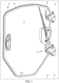
FIG. 1 is a schematic isometric view of a vehicle shown schematically including a door with a hinge assembly according to teachings of this disclosure; -
FIG. 2 is an enlarged schematic isometric view of the door hinge assembly ofFIG. 1 illustrating certain of the internal components in phantom; -
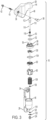
FIG. 3 is an exploded isometric schematic of the door hinge assembly ofFIGS. 1 and2 ; -
FIG. 4 is an enlarged fragmentary isometric view of the door hinge ofFIGS. 1-3 ; -
FIG. 5 is an enlarged fragmentary side elevational view of cap and top cam of the door hinge ofFIGS. 1-4 ; -
FIG. 6 is an enlarged cross-sectional view taken along the line 6-6 inFIG. 5 . - Referring to
FIG. 1 , this disclosure relates to vehicles 10 (an exemplary vehicle being shown schematically inFIG. 1 ) that include an operator's station orcab 12 having at least onedoor 14 that is hinged to thevehicle 10 by at least onehinge assembly 16 according to teachings of this disclosure to open or cover anopening 18 to thecab 12, the opening 18 being surrounded by adoorframe 20. While thevehicle 10 itself is not illustrated in detail, the disclosed system and method may be utilized with any machine orvehicle 10 that may perform an action on a surrounding environment. By way of example only, thevehicle 10 itself may be a truck, a backhoe loader, a dozer, an excavator, a motor grader, a wheel loader, a skid steer loader, a soil compactor, or a tractor. Thevehicle 10 may include aframe 22 supported on a plurality oftraction devices 24, such as wheels or belts. The operator station orcab 12 or the like may be disposed on theframe 12. - While the
door 14 may be hingedly coupled to theoperator station 12 by any appropriate number of hinges, the illustrated embodiment includes twosuch hinge assemblies 16 to open or cover thedoorframe 20 and opening 18. An enlarged view of onesuch hinge assembly 16 according to teachings of this disclosure is illustrated inFIG. 2 with a portion of the internal components of thehinge assembly 16 shown in phantom, and inFIG. 3 , which provides an exploded view of thehinge assembly 16. - The
hinge assembly 16 includes atop leaf 26 and ahinge base 28. In this embodiment, thetop leaf 26 may be coupled to thedoor 14, while thehinge base 28 may be coupled to thevehicle 10, pivotably coupling thedoor 14 to cover thedoorframe 20. It will be appreciated, however, that thetop leaf 26 could be coupled to thevehicle 10 and thehinge base 28 coupled to thedoor 14. - Any appropriate coupling arrangement or arrangements may be provided to couple the
hinge assembly 16 to thedoor 14 and thevehicle 10. In the illustrated embodiment, thehinge base 28 includes a plurality ofbores 34 through which screws, bolts, rivets, or the like (not illustrated) may be inserted to couple thehinge base 28 to thevehicle 10. Thetop leaf 26 likewise may include one ormore bores 36 through which a screw, bolt, rivet or the like may be inserted to couple thetop leaf 26 to thedoor 14. In the illustrated embodiment, however, an arrangement for allowing thedoor 14 to be quickly removed in an emergency situation is provided. That is, anemergency handle pin 38 extending from the outside of thedoor 14 may be engaged with a locking pin 40 and bushing 42 on the inside of thedoor 14. - The
top leaf 26 and thehinge base 28 each have aninternal chamber hinge assembly 16 are disposed along an axis 48. While a number of the components within thehinge assembly 16 may vary, the illustrated embodiment includes a top thrust bearing 50, a bottom thrust bearing 52 and acap 54. - The
cap 54 includes anupper channel 56 bordered by a plurality ofarcuate engagement flanges 58, the top thrust bearing 50 and bottom thrust bearing 52 being disposed within theupper channel 56. Thecap 54 further includes a lower surface from which a plurality of drivingprotrusions 59 extend. The engagement flanges 58 engage with internal structures (not visible in illustration) within theinternal chamber 44 of thetop leaf 26 such that thecap 54 rotates as thetop leaf 26 rotates with thedoor 14. - The
hinge assembly 16 further includes a top orfirst cam 60 and a bottom orsecond cam 80 disposed along the axis 48. An O-ring 104 may be disposed between thefirst cam 60 and thecap 54. Awasher 106 and acam spring 108 are likewise disposed along the axis 48 such that thecam spring 108 biases thesecond cam 80 toward thefirst cam 60. - Referring to
FIG. 4 , thefirst cam 60 has a first camupper side 62 and a first cam lower side 64. The first camlower side 62 includes a plurality of arcuately-shapedlower protrusions 66 having rampedlower surfaces 68 and first cam stops 70. While the arcuately-shapedlower protrusions 66 may be of any appropriate design, in at least one embodiment, the first cam stops 70 are longitudinally extending, disposed parallel to the axis 48. In at least one embodiment, the arcuately-shapedlower protrusions 66 present have substantially flat lower surfaces 72. In at least one embodiment, the arcuately-shapedlower protrusions 66 are spaced from one another by a plurality offirst cam gaps 74. A plurality ofrecesses 76 extend from the first camupper side 62 into the plurality of arcuately-shapedlower protrusions 66, the plurality ofrecesses 76 including a plurality of substantially radially extendingwalls 78. Rotation of thecap 54 with thetop leaf 26 and thedoor 14 is transmitted to the top orfirst cam 60 as the drivingprotrusion 59 engage with the plurality ofrecesses 76 in the first camupper side 62. - The
second cam 80 has a second camupper side 82 and a second camlower side 84. The second camupper side 82 includes a plurality of arcuately-shapedupper protrusions 86 having rampedupper surfaces 88 and second cam stops 90. The arcuately-shapedupper protrusions 86 are the same in number and are spaced to correspond to the arcuately-shapedlower protrusion 66 of thefirst cam 60 such that the rampedlower surfaces 68 of thefirst cam 60 ride along the rampedupper surfaces 88 of thesecond cam 80. As with arcuately-shapedlower protrusions 66 of thefirst cam 60, the arcuately-shapedupper protrusions 86 may be of any appropriate design so long as the arcuately-shapedupper protrusions 86 cooperate with the arcuately-shapedupper protrusions 66 as at least one of the first andsecond cams upper protrusions 86 present substantially flat upper surfaces 92. In at least one embodiment, the arcuately-shapedupper protrusions 86 are spaced from one another by a plurality ofsecond cam gaps 94. - As the
second cam 80 further includes acylindrical base 96, which may include acavity 98 within which thecam spring 108 may be at least partially disposed. Thecylindrical base 96 may additionally include one or moreengaging structures 100, which may engage with engaging structure (not visible) within theinternal chamber 46 of thehinge base 28 to inhibit rotation. In the illustrated embodiment, the engagingstructures 100 of thecylindrical base 96 include a plurality of longitudinally extending channels, while the engaging structures of thehinge base 28 include one or more radially extending protrusions disposed to engage the longitudinally extending channels. - The
cam spring 108 is disposed to exert a biasing force, biasing thesecond cam 80 toward thefirst cam 60 in order to maintain contact between the rampedlower surfaces 68 of thefirst cam 60 and the rampedupper surfaces 88 of thesecond cam 80. It will be appreciated, however, that thefirst cam 60 could alternatively or additionally be biased toward thesecond cam 80. - Those of skill in the art will appreciate that the
first cam 60 is rotatably disposed relative to thesecond cam 80. In the illustrated embodiment, thecap 54 is coupled for rotation with thetop leaf 26 by thearcuate engagement flanges 58, thecap 54 further transmitting rotation to thefirst cam 60 by way of the drivingprotrusions 59. Thefirst cam 60 rotates relative to thesecond cam 80, which is preventing from rotation relative to thehinge base 28 by way of the engagingstructure 100. In this way, with thetop leaf 26 coupled to thedoor 14 and thehinge base 28 coupled to thevehicle 10, thefirst cam 60 is disposed to rotate relative to thesecond cam 80 as thedoor 14 is opened or closed. In this way, as relative rotation occurs between the first andsecond cams lower surfaces 68 of thefirst cam 60 ride along the rampedupper surfaces 88 of thesecond cam 80. In the illustrated embodiment, as thedoor 14 is opened, the rampedlower surfaces 68 of thefirst cam 60 ride down the rampedupper surfaces 88 of thesecond cam 80, thesecond cam 80 being biased toward thefirst cam 60 by way of thecam spring 108. The first andsecond cams second cams - The internal components of the
hinge assembly 16, that is, the top thrust bearing 50, bottom thrust bearing 52,cap 54, O-ring 104,first cam 60,second cam 80,cam spring 108, andwasher 106, are axially disposed along axis 48 within theinternal chambers top leaf 26 and hingebase 28, respectively. In order to maintain this alignment and to couple the components, ahinge pin 110 is provided. Thehinge pin 110 includes ahead 112 and ashaft 114 having a threadeddistal end 116. Thehinge pin 110 is disposed along the axis 48, thehinge pin 110 extending through the central openings in each of the internal components of thehinge assembly 16. In at least one embodiment, thedistal end 116 of thehinge pin 110 extends through anaxially extending opening 118 of thehinge base 28, as well as aseal 120, and lockingwasher 122 before being received in alocknut 124 dispose along the bottom of thehinge base 28. - In accordance with an aspect of this disclosure, an
elastomeric bushing 130 is disposed betweencap 54, which operates as a driving member, and thefirst cam 60, which operates as a driven member as thetop leaf 26 rotates relative to thehinge base 28. Referring toFIG. 4 , theelastomeric bushing 130 includes adisk 132, which includes a plurality ofinterruptions 134. Thedisk 132 includes acentral bore 135 through which thehinge pin 110 may be extended. A plurality oflobes 136 extend from a lower surface of thedisk 132 in a direction parallel to the central axis 48. Thelobes 136 extend generally radially. - In assembly, the
lobes 136 extend into to therecesses 76 of thefirst cam 60. In the illustrated embodiment, in order to conform to the interior of the arcuately-shapedlower protrusions 66, thelobes 136 alternate between relativelyshort lobes 138 and relativelylong lobes 140 extending along opposite sides of theinterruptions 134 in thedisk 132 of theelastomeric bushing 130, that is, alternating around thedisk 132. In this way, thelong lobes 140 are disposed against the inside surface of the first cam stops 70 of the arcuately-shapedlower protrusions 66 of thefirst cam 60, while theshort lobes 138 are disposed at the more shallow end of the arcuately-shapedlower protrusions 66. In the illustrated embodiment of theelastomeric bushing 130, thelobes 136 are of different thicknesses. That is, thelong lobes 140 are relatively thick, and theshort lobes 138 are relatively thin. In at least one embodiment, the distal ends of thelobes 136 are ramped to conform to the interior ramped surfaces of the arcuately-shapedlower protrusions 66. It will be appreciated, however, that thelobes 136 may be of an alternative configuration. For example, in at least some embodiments, thelobes 136 may all be of the same thickness, and in at least some embodiments, thelobes 136 may extend only along one side of theinterruptions 134 in thedisk 132. - In order to cushion the transmission of force between the
cap 54 and thefirst cam 60, the drivingprotrusions 59 of thecap 54 are disposed in theinterruptions 134 in thedisk 132 of theelastomeric bushing 130. Thelobes 136 of theelastomeric bushing 130 and the drivingprotrusions 59 of thecap 54 are disposed within therecesses 76 of the first camupper side 62. That is, both thelobes 136 and the drivingprotrusions 59 are disposed within the arcuately-shapedlower protrusions 66 of thefirst cam 60 substantially adjacent the plurality of substantially radially extendingwalls 78 of therecesses 76 of thefirst cam 60. In this way, thelobes 140 cushion the confrontation of the drivingprotrusions 59 with plurality of substantially radially extendingwalls 78 of the arcuately-shapedlower protrusions 66 of thefirst cam 60 as thecap 54 rotates in a driving direction, as illustrated, a counter-clockwise direction, while thelobes 138 cushion the confrontation of the drivingprotrusions 66 with the other of the plurality of substantially radially extendingwalls 78 of the arcuately-shapedlower protrusions 66 as thecap 54 rotates in other than a driving direction, as illustrated, a clockwise direction. - As depicted herein, an embodiment has three driving
protrusions 59, three arcuately-shapedlower protrusions 66, three arcuately-shapedupper protrusions 86, threeshort lobes 138, and threelong lobes 140. Smaller and larger numbers of these components are contemplated. In at least some embodiments, these components sized such that there is minimal clearance between the drivingprotrusions 59 assembled into position between theshort lobes 138 andlong lobes 140 of theelastomeric bushing 130 disposed within therecesses 76 of the first camupper side 62. In at least some embodiments, the assembly of the drivingprotrusions 59 between theshort lobes 138 andlong lobes 140 of theelastomeric bushing 130 into therecesses 76 of the first camupper side 62 places one or both of theshort lobes 138 andlong lobes 140 in compression. In at least some embodiments, these components could be sized so as to include clearance space between one or more of the drivingprotrusions 59, theshort lobes 138, thelong lobes 140, and therecesses 76 of the first camupper side 62, such that theshort lobes 138 andlong lobes 140 only come into contact with portions of therecesses 76 and/or the drivingprotrusions 59 at certain relative rotational positions between thetop leaf 26 and hingebase 28. Although these components are shown as spaced symmetrically around axis 48, asymmetric configurations are also contemplated. - The
elastomeric bushing 130 may be of any appropriate elastomeric composition that acts to cushion the driving movement. For example, theelastomeric bushing 130 may be formed of Hytrel®. Theelastomeric bushing 130 may be formed by any appropriate fabrication method. By way of example only, injection, transfer, or compression molding may be appropriate for manufacturing theelastomeric bushing 130. - According to another aspect of this disclosure, the disposition of the
elastomeric cushion 130 between driving member, here, the drivingprotrusions 59 of thecap 54, and the driven member of thehinge assembly 16, here, the interior recesses 76 of the arcuately-shapedlower protrusions 66 of thefirst cam 60, may have a cushioning effect, cushioning the impact during operation of thedoor 14. - In some embodiments, this cushioning effect may help to inhibit damage to the
hinge assembly 16. In at least some embodiments, this may reduce downtime for repairs or replacement, and may reduce maintenance costs. - While the disclosed hinge and hinge assembly has been described with respect to vehicles having doors, the design may be applied to other machines having doors. Moreover, although it will be appreciated that the foregoing description provides useful examples of the particular designs of the components of the disclosed hinge and hinge assembly, it should be appreciated that other implementations of the disclosed principles will differ in detail from the foregoing examples. All references to the disclosure or examples thereof are intended to reference the particular example being discussed at that point and are not intended to imply any limitation as to the scope of the disclosure more generally. All language of distinction and disparagement with respect to certain features is intended to indicate a lack of preference for the features of interest, but not to exclude such from the scope of the disclosure entirely unless otherwise specifically indicated.
- Recitation of ranges of values herein are merely intended to serve as a shorthand method of referring individually to each separate value falling within the range, unless otherwise indicated herein, and each separate value is incorporated into the specification as if it were individually recited herein.
Claims (10)
- A hinge assembly (16) for pivotably coupling a first structure relative to a second structure, the hinge assembly (16) comprising:a driving member (54), the driving member (54) being configured for coupling to the first structure,a driven member (60), andan elastomeric bushing (130), the elastomeric bushing (130) being disposed between the driving member (54) and the driven member (60),said driving member (54), said driven member (60), and said elastomeric bushing (130) being disposed along a central axis (48).
- The hinge assembly (16) of claim 1 wherein the elastomeric bushing (130) includes an interrupted disk (132) from which a plurality of lobes (136) extend in a direction parallel to the central axis (48), said plurality of lobes (136) being separated by a plurality of interruptions (134) in said disk (132), wherein the driving member (54) includes a plurality of driving protrusions (59), said driving protrusions (59) extending in a direction parallel to the central axis (48) and being disposed within said plurality of interruptions (134) in said disk (132), and wherein the driven member (60) includes a plurality of recesses (76), said plurality of lobes (136) being disposed within said plurality of recesses (76) such that the plurality of lobes (136) are disposed between the plurality of driving protrusions (59) and the plurality of recesses (76).
- The hinge assembly (16) of claim 2 wherein the plurality of lobes (136) includes a plurality of thin lobes (138) and a plurality of thick lobes (140) wherein said thin lobes (138) are thin relative to said thick lobes (140), said thick and thin lobes (140, 138) alternatingly extending about a periphery of the disk (132), and wherein the plurality of lobes (136) includes a plurality of short lobes (138) and a plurality of long lobes (140) wherein said long lobes (140) are long relative to said short lobes (138).
- The hinge assembly (16) of claim 2 wherein the driven member (60) is a first cam (60), the plurality of recesses (76) of the driven member (60) being defined by generally arcutely-shaped lower protrusions (66) including substantially radially extending walls defining the plurality of recesses (76) such that the plurality of lobes (136) are disposed between the plurality of driving protrusions (59) and the substantially radially extending walls of the recesses (76) of the arcutely-shaped lower protrusions (66), the arcutely-shaped lower protrusions (66) including ramped lower surfaces (68).
- The hinge assembly (16) of claim 4 further including a second cam (80) including a plurality of ramped upper surfaces (88), the plurality of ramped lower surfaces (68) of the first cam (60) being disposed to ride on the plurality of ramped upper surfaces (88) of the second cam (80).
- The hinge assembly (16) of any of claim 5 configured for pivotably coupling a door (14) to a vehicle (10), the hinge assembly (16) wherein:the driving member (54) is configured to be coupled to said door (14),the first cam (60) includes a first cam upper side (62) and a first cam lower side (64), the first cam lower side (64) defining the plurality of arcutely-shaped lower protrusions (66) having ramped lower surfaces (68) and first cam stops (70), the first cam upper side (62) defining the plurality of recesses (76) extending within the plurality of arcutely-shaped lower protrusions (66), the plurality of recesses (76) being at least partially defined by the plurality of substantially radially extending walls,the second cam (80) includes a second cam upper side and a second cam lower side, the second cam upper side including a plurality of arcuately-shaped upper protrusions (86) including the plurality of ramped upper surfaces (88) and a plurality of second cam stops (90), said second cam (80) being configured to be coupled to the vehicle (10),the first cam (60) and the second cam (80) being disposed along said central axis (48) so that the ramped lower surfaces (68) of the plurality of arcutely-shaped lower protrusions (66) are configured to ride along the ramped upper surfaces (88) of the plurality of arcuately-shaped upper protrusions (86) as the first cam (60) is driven to rotate relative to the second cam (80) about said central axis (48), andthe elastomeric bushing (130) is disposed between the driving member (54) and the first cam (60), the plurality of lobes (136) extending in a generally radial direction parallel to the central axis (48).
- The hinge assembly (16) of claim 6 wherein the plurality of lobes (136) includes at least one of a plurality of thin lobes (138) and a plurality of thick lobes (140) wherein said thin lobes (138) are thin relative to said thick lobes (140), said thick and thin lobes (140, 138) alternatingly extending about a periphery of the disk (132), or a plurality of short lobes (138) and a plurality of long lobes (140), wherein said long lobes (140) are longer relative to said short lobes (138).
- The hinge assembly (16) of claim 6 wherein the plurality of lobes (136) disposed between the driving protrusions (59) and the plurality of substantially radially extending walls of the recesses (76) of first cam (60) to cushion the engagement of the driving protrusions (59) with the substantially radially extending walls when the driving member (54) is rotated in a driving direction.
- The hinge assembly (16) of claim 8 wherein the lobes of the plurality of lobes (136) are disposed between the driving protrusions (59) and the plurality of radially extending walls of the recesses (76) of the first cam (60) such that the plurality of lobes (136) cushion the engagement of the driving protrusion (59) with the plurality of radially extending walls of the recesses (76) of the first cam (60) when the driving member (54) is rotated in a direction other than the driving direction.
- The hinge assembly (16) of claim 9 wherein the driving member (54), the elastomeric bushing (130), the first cam (60) and the second cam (80) each include a respective bore along the central axis (48), and the hinge assembly (16) further includes a hinge pin (110) extending through said respective bores, the hinge pin (110) being coupled with the hinge base (28).
Applications Claiming Priority (1)
| Application Number | Priority Date | Filing Date | Title |
|---|---|---|---|
| US18/527,217 US12497811B2 (en) | 2023-12-01 | 2023-12-01 | Door hinge cushioning arrangement |
Publications (1)
| Publication Number | Publication Date |
|---|---|
| EP4563781A1 true EP4563781A1 (en) | 2025-06-04 |
Family
ID=93463328
Family Applications (1)
| Application Number | Title | Priority Date | Filing Date |
|---|---|---|---|
| EP24211936.0A Pending EP4563781A1 (en) | 2023-12-01 | 2024-11-08 | Door hinge cushioning arrangement |
Country Status (5)
| Country | Link |
|---|---|
| US (1) | US12497811B2 (en) |
| EP (1) | EP4563781A1 (en) |
| CN (1) | CN120083430A (en) |
| AU (1) | AU2024264605A1 (en) |
| CA (1) | CA3257639A1 (en) |
Citations (5)
| Publication number | Priority date | Publication date | Assignee | Title |
|---|---|---|---|---|
| US20070119022A1 (en) * | 2004-01-09 | 2007-05-31 | Kenji Tomizawa | Hinge device |
| US20090007379A1 (en) * | 2007-07-06 | 2009-01-08 | Shenzhen Futaihong Precision Industry Co., Ltd. | Automatically opening hinge assembly for portable electronic devices |
| US20210025130A1 (en) | 2018-05-29 | 2021-01-28 | Komatsu Ltd. | Cab for work machine and work machine |
| CN213742834U (en) * | 2020-07-07 | 2021-07-20 | 昆山市广源行金属工业有限公司 | Detachable vehicle door hinge |
| WO2023121645A1 (en) * | 2021-12-20 | 2023-06-29 | Multimatic Patentco Llc | Automotive door hinge with door close assist |
Family Cites Families (27)
| Publication number | Priority date | Publication date | Assignee | Title |
|---|---|---|---|---|
| US3436069A (en) * | 1967-03-13 | 1969-04-01 | Curtis W Henschen | Bearing assembly for elastic joints |
| US3591216A (en) * | 1969-02-26 | 1971-07-06 | Burdsall & Ward Co | Bearing fastener and assembly |
| US3754543A (en) * | 1972-03-10 | 1973-08-28 | Briggs & Stratton Corp | Rope starter for small engines |
| US4722502A (en) * | 1985-10-02 | 1988-02-02 | American Sterilizer Company | Adjustable support system |
| US20020112319A1 (en) * | 2001-02-21 | 2002-08-22 | Makoto Kida | Hinge |
| JP3906702B2 (en) * | 2002-02-12 | 2007-04-18 | 松下電器産業株式会社 | Switchgear and electronic device using the same |
| JP3972795B2 (en) * | 2002-10-31 | 2007-09-05 | 松下電器産業株式会社 | Switchgear |
| CN2698940Y (en) * | 2004-05-25 | 2005-05-11 | 耐亚科技有限公司 | Cabinet hinge device with buffer and retractable cover |
| KR20070027576A (en) * | 2004-06-08 | 2007-03-09 | 암페놀 티 앤드 엠 안테나즈 | Parallel Plate Swivel Hinges for Portable Devices |
| US7120967B2 (en) * | 2004-07-01 | 2006-10-17 | Radio Systems Corporation | Pet door hinge |
| CN1932316B (en) * | 2005-09-16 | 2010-09-29 | 深圳富泰宏精密工业有限公司 | Multi-stage shaft structure |
| US7699378B2 (en) * | 2007-08-28 | 2010-04-20 | Ventra Group, Inc. | Motion assist mechanism for a vehicle tailgate |
| US7631397B2 (en) * | 2007-09-06 | 2009-12-15 | Cheng Uei Precision Industry Co., Ltd. | Hinge |
| US7814620B2 (en) * | 2008-01-29 | 2010-10-19 | Cheng Uei Precision Industry Co., Ltd. | Hinge |
| US7954203B2 (en) * | 2008-12-19 | 2011-06-07 | Shin Zu Shing Co., Ltd. | Hinge and an electronic device with the hinge |
| US8066320B1 (en) * | 2010-11-16 | 2011-11-29 | Chrysler Group Llc | Door hinge |
| BR202012007468U2 (en) * | 2012-04-02 | 2013-11-19 | Francisco Alan Freitas Marinho | CONSTRUCTIVE ARRANGEMENT IN ELASTERIC SPRING DOORS LOCK |
| US9016773B2 (en) * | 2012-12-31 | 2015-04-28 | E.R. Wagner Manufacturing Co. | Hinge mechanism for a vehicle hood |
| US20150167275A1 (en) | 2013-12-12 | 2015-06-18 | Caterpillar Inc. | Operator cab for earth moving machines |
| US20150345203A1 (en) * | 2014-05-28 | 2015-12-03 | Nuova Star S.P.A. | Hinge for doors of electrical household appliances |
| KR101618052B1 (en) | 2015-08-19 | 2016-05-09 | 주식회사 서연탑메탈 | Heavy construction equipment, switching control for work of the vehicle door hinge system |
| US9739523B1 (en) * | 2016-07-25 | 2017-08-22 | Haier Us Appliance Solutions, Inc. | Hinge assembly for a refrigerator appliance |
| KR101691149B1 (en) * | 2016-10-27 | 2016-12-29 | 주식회사 이피텍 | Device of door hinge for washing machine |
| US11002055B2 (en) * | 2019-09-09 | 2021-05-11 | Schlage Lock Company Llc | Door control armature assemblies |
| US12312847B2 (en) * | 2019-12-03 | 2025-05-27 | Steven Alonzi | Door hinge with integrated door check |
| EP4098833B1 (en) * | 2021-05-31 | 2024-10-09 | dormakaba Deutschland GmbH | Door actuating linkage |
| US20250003464A1 (en) * | 2023-06-30 | 2025-01-02 | Rivian Ip Holdings, Llc | Isolation bushings with conforming multi-part covers |
-
2023
- 2023-12-01 US US18/527,217 patent/US12497811B2/en active Active
-
2024
- 2024-11-08 EP EP24211936.0A patent/EP4563781A1/en active Pending
- 2024-11-13 AU AU2024264605A patent/AU2024264605A1/en active Pending
- 2024-11-22 CN CN202411682884.3A patent/CN120083430A/en active Pending
- 2024-11-27 CA CA3257639A patent/CA3257639A1/en active Pending
Patent Citations (5)
| Publication number | Priority date | Publication date | Assignee | Title |
|---|---|---|---|---|
| US20070119022A1 (en) * | 2004-01-09 | 2007-05-31 | Kenji Tomizawa | Hinge device |
| US20090007379A1 (en) * | 2007-07-06 | 2009-01-08 | Shenzhen Futaihong Precision Industry Co., Ltd. | Automatically opening hinge assembly for portable electronic devices |
| US20210025130A1 (en) | 2018-05-29 | 2021-01-28 | Komatsu Ltd. | Cab for work machine and work machine |
| CN213742834U (en) * | 2020-07-07 | 2021-07-20 | 昆山市广源行金属工业有限公司 | Detachable vehicle door hinge |
| WO2023121645A1 (en) * | 2021-12-20 | 2023-06-29 | Multimatic Patentco Llc | Automotive door hinge with door close assist |
Also Published As
| Publication number | Publication date |
|---|---|
| CA3257639A1 (en) | 2025-11-29 |
| AU2024264605A1 (en) | 2025-06-19 |
| US20250179852A1 (en) | 2025-06-05 |
| US12497811B2 (en) | 2025-12-16 |
| CN120083430A (en) | 2025-06-03 |
Similar Documents
| Publication | Publication Date | Title |
|---|---|---|
| CN102187038B (en) | Cab for construction machine | |
| US6715808B2 (en) | Power striker mechanism with backdrive prevention | |
| EP1958809A1 (en) | Window arrangement for a construction vehicle | |
| DE102006055630A1 (en) | Glove box device | |
| US12497811B2 (en) | Door hinge cushioning arrangement | |
| EP3719215B1 (en) | Work machine cab and work machine | |
| CA3140932A1 (en) | Locking device and hopper car | |
| JPWO2011030666A1 (en) | Door hanging device and door device provided with the same | |
| JPWO2005049412A1 (en) | Idler guide device | |
| CN112292277A (en) | Opening-closing mechanism for cover plate of guide rail | |
| KR100348046B1 (en) | door hinge capable of door checker | |
| EP1257720B1 (en) | Power striker mechanism with backdrive prevention | |
| EP4096830B1 (en) | Restraining of service access to hsi crusher chamber | |
| CA2685945C (en) | Output shaft, teeter lever and pinion gear arrangement for pneumatic differential engine | |
| WO2001044628A1 (en) | Adjusting element for a rotary piston | |
| DE102014009091A1 (en) | Swivel motor adjuster for a camshaft | |
| EP1726760A2 (en) | Hinge | |
| JP5588101B2 (en) | Elevator operation panel | |
| JP2009024414A (en) | Hinge structure and cab for construction machine having the same | |
| US11725437B1 (en) | Hinge assembly for a work vehicle door | |
| CN211776649U (en) | Modular latch for construction vehicle | |
| KR100474457B1 (en) | An opening and shutting device for door of freight car | |
| JP2013113023A (en) | Mounting structure for key cylinder | |
| CA2621591A1 (en) | Window arrangement for a construction vehicle |
Legal Events
| Date | Code | Title | Description |
|---|---|---|---|
| PUAI | Public reference made under article 153(3) epc to a published international application that has entered the european phase |
Free format text: ORIGINAL CODE: 0009012 |
|
| STAA | Information on the status of an ep patent application or granted ep patent |
Free format text: STATUS: THE APPLICATION HAS BEEN PUBLISHED |
|
| AK | Designated contracting states |
Kind code of ref document: A1 Designated state(s): AL AT BE BG CH CY CZ DE DK EE ES FI FR GB GR HR HU IE IS IT LI LT LU LV MC ME MK MT NL NO PL PT RO RS SE SI SK SM TR |
|
| STAA | Information on the status of an ep patent application or granted ep patent |
Free format text: STATUS: REQUEST FOR EXAMINATION WAS MADE |
|
| 17P | Request for examination filed |
Effective date: 20250917 |
|
| STAA | Information on the status of an ep patent application or granted ep patent |
Free format text: STATUS: EXAMINATION IS IN PROGRESS |
|
| 17Q | First examination report despatched |
Effective date: 20260128 |