EP4563738A1 - Clothes treatment apparatus - Google Patents
Clothes treatment apparatus Download PDFInfo
- Publication number
- EP4563738A1 EP4563738A1 EP23845077.9A EP23845077A EP4563738A1 EP 4563738 A1 EP4563738 A1 EP 4563738A1 EP 23845077 A EP23845077 A EP 23845077A EP 4563738 A1 EP4563738 A1 EP 4563738A1
- Authority
- EP
- European Patent Office
- Prior art keywords
- component
- treatment apparatus
- clothing treatment
- movement component
- working
- Prior art date
- Legal status (The legal status is an assumption and is not a legal conclusion. Google has not performed a legal analysis and makes no representation as to the accuracy of the status listed.)
- Pending
Links
Images


Classifications
-
- D—TEXTILES; PAPER
- D06—TREATMENT OF TEXTILES OR THE LIKE; LAUNDERING; FLEXIBLE MATERIALS NOT OTHERWISE PROVIDED FOR
- D06F—LAUNDERING, DRYING, IRONING, PRESSING OR FOLDING TEXTILE ARTICLES
- D06F31/00—Washing installations comprising an assembly of several washing machines or washing units, e.g. continuous flow assemblies
-
- D—TEXTILES; PAPER
- D06—TREATMENT OF TEXTILES OR THE LIKE; LAUNDERING; FLEXIBLE MATERIALS NOT OTHERWISE PROVIDED FOR
- D06F—LAUNDERING, DRYING, IRONING, PRESSING OR FOLDING TEXTILE ARTICLES
- D06F17/00—Washing machines having receptacles, stationary for washing purposes, wherein the washing action is effected solely by circulation or agitation of the washing liquid
- D06F17/06—Washing machines having receptacles, stationary for washing purposes, wherein the washing action is effected solely by circulation or agitation of the washing liquid by rotary impellers
-
- D—TEXTILES; PAPER
- D06—TREATMENT OF TEXTILES OR THE LIKE; LAUNDERING; FLEXIBLE MATERIALS NOT OTHERWISE PROVIDED FOR
- D06F—LAUNDERING, DRYING, IRONING, PRESSING OR FOLDING TEXTILE ARTICLES
- D06F39/00—Details of washing machines not specific to a single type of machines covered by groups D06F9/00 - D06F27/00
- D06F39/12—Casings; Tubs
- D06F39/125—Supporting arrangements for the casing, e.g. rollers or legs
-
- D—TEXTILES; PAPER
- D06—TREATMENT OF TEXTILES OR THE LIKE; LAUNDERING; FLEXIBLE MATERIALS NOT OTHERWISE PROVIDED FOR
- D06F—LAUNDERING, DRYING, IRONING, PRESSING OR FOLDING TEXTILE ARTICLES
- D06F23/00—Washing machines with receptacles, e.g. perforated, having a rotary movement, e.g. oscillatory movement, the receptacle serving both for washing and for centrifugally separating water from the laundry
- D06F23/04—Washing machines with receptacles, e.g. perforated, having a rotary movement, e.g. oscillatory movement, the receptacle serving both for washing and for centrifugally separating water from the laundry and rotating or oscillating about a vertical axis
Definitions
- the present application relates to the technical field of clothing treatment, and specifically provides a clothing treatment apparatus.
- This type of clothing treatment apparatus uses a pull-out machine to put in laundry or other clothing and shoes for washing, drying or deodorizing, or take them out; it mainly includes an assembly of drawer and cabinet.
- the washing or other treatment of laundry is mainly completed inside the drawer, and the cabinet mainly plays a role of load-bearing and fixing. Therefore, the connection method between the drawer and the cabinet is particularly important.
- connection is mostly achieved through a sliding rail.
- the sliding rail is mainly designed to bear a vertical force, and has poor reliability in the horizontal direction. After a long time, the sliding rail will be damaged, making the drawer unable to be pulled out smoothly and ultimately completely damaged.
- the present application aims to solve the above technical problem, that is, to solve the problem that the connection structure between the drawer and the cabinet in the prior art cannot effectively bear both horizontal and vertical forces.
- the present application provides a clothing treatment apparatus, which includes a first movement component, a second movement component, and a pull-out working component;
- the second movement component is a sliding rail with protruding guide blocks arranged on both sides and a slideway arranged in the middle; the groove and the climbing boss are arranged on the middle slideway, the platforms are arranged on the protruding guide blocks, and the support component is arranged to be capable of abutting against the platforms when the first movement component moves to the groove.
- an operating side of the clothing treatment apparatus is a front side, and there is a height difference between front and rear sides of the second movement component.
- the first movement component is a rear roller, and correspondingly, the groove and the platforms are arranged on a rear side of the slideway.
- the clothing treatment apparatus further includes a front roller, which is arranged on a front side of the working component and is arranged to be capable of abutting against the ground.
- the first movement component is a sliding device, which is arranged to be capable of sliding into or out of the groove.
- the sliding device is a slider with rounded corners on the side edges.
- a damping device is also provided on a rear side of the second movement component.
- the damping device is a spring.
- the second movement component is a sliding rail with a protruding guide block arranged on an outer side and a slideway arranged on an inner side; the groove and the climbing boss are arranged on the slideway on the inner side, the platform is arranged on the protruding guide block, and the support component is arranged to be capable of abutting against the platform when the first movement component moves to the groove.
- the second movement component is a sliding rail with a protruding guide block arranged on an inner side and a slideway arranged on an outer side; the groove and the climbing boss are arranged on the slideway on the outer side, the platform is arranged on the protruding guide block, and the support component is arranged to be capable of abutting against the platform when the first movement component moves to the groove.
- a sensor capable of detecting whether the first movement component has stopped in place is also provided on an inner side of the groove.
- the first movement component is a structure that can be extended and retracted up and down, so that the sensor can be triggered when the first movement component moves to the groove.
- an insertable buckle is also provided on the working component, and the clothing treatment apparatus also includes a cabinet on which a slot matching with the buckle is provided; the buckle is arranged such that it can move toward the slot during the process of the working component entering the working position, and can be inserted into the slot after the working component enters the working position.
- the support component is a support block.
- the protruding guide blocks are integrally formed with the platforms.
- a height of the rear side of the second movement component is higher than a height of the front side of the second movement component.
- the support component can support part or all of the gravity of the working component, so that the support force of the first movement component is reduced or cancelled.
- the horizontal and vertical forces received by the first movement component during the operation of the clothing treatment apparatus can be reduced or cancelled, thereby avoiding the problem of unsmooth pulling of the clothing treatment apparatus caused by damage to the first movement component due to the forces.
- the present application provides a clothing treatment apparatus, which includes a first movement component, a second movement component, and a pull-out working component;
- an operating side of the clothing treatment apparatus is a front side, and there is a height difference between front and rear sides of the second movement component.
- the first movement component is a rear roller, and correspondingly, the groove is arranged on a rear side of the slideway.
- the first movement component is a sliding device, which is arranged to be capable of sliding into or out of the groove.
- the sliding device is a slider with rounded corners on the side edges.
- a damping device is also provided on a rear side of the second movement component.
- the damping device is a spring.
- a sensor capable of detecting whether the first movement component has stopped in place is also provided on an inner side of the groove.
- the first movement component is a structure that can be extended and retracted up and down, so that the sensor can be triggered when the first movement component moves to the groove.
- an insertable buckle is also provided on the working component, and the clothing treatment apparatus also includes a cabinet on which a slot matching with the buckle is provided; the buckle is arranged such that it can move toward the slot during the process of the working component entering the working position, and can be inserted into the slot after the working component enters the working position.
- the support component is a support block.
- the protruding stoppers are integrally formed with the protruding guide blocks.
- a height of the rear side of the second movement component is higher than a height of the front side of the second movement component.
- the support component can support part or all of the gravity of the working component, so that the support force of the first movement component is reduced or cancelled.
- the horizontal and vertical forces received by the first movement component during the operation of the clothing treatment apparatus can be reduced or cancelled, thereby avoiding the problem of unsmooth pulling of the clothing treatment apparatus caused by damage to the first movement component due to the forces.
- the design of the protruding stoppers also prevents the front roller from swinging left and right after the working component is supported in place, achieving more stable fixation.
- the present application provides a clothing treatment apparatus, which includes a first movement component, a second movement component, and a pull-out working component;
- an opening size of the anti-detachment concave rail is larger than a thickness size of the anti-detachment protrusion.
- an operating side of the clothing treatment apparatus is a front side, and there is a height difference between front and rear sides of the second movement component.
- the first movement component is a rear roller, and correspondingly, the groove is arranged on a rear side of the slideway.
- the clothing treatment apparatus also includes a front roller, which is arranged on a front side of the working component and is arranged to be capable of abutting against the ground.
- the first movement component is a sliding device, which is arranged to be capable of sliding into or out of the groove.
- the sliding device is a slider with rounded corners on the side edges.
- a damping device is also provided on a rear side of the second movement component.
- the damping device is a spring.
- a sensor capable of detecting whether the first movement component has stopped in place is also provided on an inner side of the groove.
- the first movement component is a structure that can be extended and retracted up and down, so that the sensor can be triggered when the first movement component moves to the groove.
- an insertable buckle is also provided on the working component, and the clothing treatment apparatus also includes a cabinet on which a slot matching with the buckle is provided; the buckle is arranged such that it can move toward the slot during the process of the working component entering the working position, and can be inserted into the slot after the working component enters the working position.
- the support component is a support block.
- a height of the rear side of the second movement component is higher than a height of the front side of the second movement component.
- the support component can support part or all of the gravity of the working component, so that the support force of the first movement component is reduced or cancelled.
- the horizontal and vertical forces received by the first movement component during the operation of the clothing treatment apparatus can be reduced or cancelled, thereby avoiding the problem of unsmooth pulling of the clothing treatment apparatus caused by damage to the first movement component due to the forces.
- the design of the anti-detachment concave rails ensures that the working component will not detach from the sliding rail under any circumstances, increasing the safety of the product.
- connection may be a fixed connection, or a detachable connection, or an integral connection; it may be a mechanical connection, or an electrical connection; it may be a direct connection, or an indirect connection implemented through an intermediate medium.
- install or connect
- connection should be understood in a broad sense; for example, the connection may be a fixed connection, or a detachable connection, or an integral connection; it may be a mechanical connection, or an electrical connection; it may be a direct connection, or an indirect connection implemented through an intermediate medium.
- the present application proposes a clothing treatment apparatus, which includes a first movement component, a second movement component, and a pull-out working component 3.
- the second movement component is provided with a groove 23.
- the first movement component may be a rear roller 1
- the second movement component may be a sliding rail 2.
- the solution of the sliding rail 2 may be the sliding rail 2 with protruding guide blocks 21 arranged on both sides and a slideway 22 arranged in the middle, as shown in FIGS. 2 and 11 .
- the groove 23 is arranged on a rear side of the slideway 22 to match with the first movement component.
- the working component 3 can be a pull-out type pulsator washing machine, which can be directly slidably arranged on the sliding rail 2; alternatively, as shown in FIG. 2 , the pulsator washing machine can be placed in a box ( FIG. 2 only shows the box, and the body of the pulsator washing machine is not shown), and then slidably arranged on the sliding rail.
- a support component 31 is provided below the working component 3, and the rear roller 1 of the first movement component is also provided on the working component 3.
- the rear roller 1 is indirectly arranged on the working component 3 by placing it on the support component 31, as shown in FIG. 7 .
- the rear roller 1 can drive the working component 3 to move on the sliding rail 2 during the pulling process of the working component 3; after the working component 3 reaches a working position, the rear roller 1 moves to the groove 23, as shown in FIG. 9 or FIG. 10 , so that the rear roller 1 does not support the gravity of the working component 3 or supports part of the gravity of the working component 3, and the support component 31 supports the remaining part of the gravity of the working component 3.
- the support component 31 supports the remaining part of the gravity of the working component 3.
- the rear roller 1 directly falls into the groove 23 completely and is suspended, at this time, the support component 31 will fully bear the gravity of the working component 3.
- the rear roller 1 is provided with an elastic structure such as an elastic member like a spring arranged above the rear roller 1, as shown in FIG. 14 , then the rear roller 1 can still provide certain support after abutting a bottom surface of the groove 23; at this time, the support component 31 plays a role in supporting the remaining part of the gravity of the working component 3.
- support positions of the support component 31 in the above solution can be located on the protruding guide blocks 21 on both sides of the sliding rail 2, in which the support component 31 abuts against the protruding guide blocks 21 to transmit the force to the sliding rail 2.
- the support component 31 and the sliding rail 2 can also be staggered so that the force is directly transmitted to a bottom surface of a cabinet 7 (this solution is not shown in the drawings), or if the clothing treatment apparatus does not have the cabinet 7, the force can also be directly transmitted to the ground or an installation platform (this solution is not shown in the drawings).
- the present application enables the rear roller 1 to fall into the groove 23 after the working component 3 is pulled out to put the clothing in and pushed back to the working position, so that the support component 31 supports the majority of the force, and the rear roller 1 no longer bears the eccentric force of the washing machine during the washing and vibrating process, that is, the rear roller 1 no longer bears the horizontal force, which is in turn borne by the support component 31.
- the service life of the rear roller 1 can be greatly extended.
- the washing machine can also be supported more stably and firmly during the washing process, thus reducing the vibration frequency of the washing machine and reducing the overall vibration noise of the clothing treatment apparatus.
- the support component 31 is a support block shown in FIG. 7 ; a bottom surface of the support block can be configured as a surface with a higher coefficient of friction, or the support block is overall made of a material with higher friction, such as rubber, further preventing the support component 31 from slipping or vibrating and displacing.
- the clothing treatment apparatus of the present application is further provided with a front roller 4, which is arranged on a front side of the working component 3 and which is arranged to be capable of contacting with the ground to achieve support at a front end during the pulling process. Therefore, the overall structure does not rely entirely on the sliding rail to complete, and part of the force can be distributed to the front roller 4.
- a damping device 5 is also provided on a rear side of the rear roller 1.
- the damping device 5 is preferably a spring; of course, it can also adopt other damping structures, such as a damping rod or an elastic block, so as to avoid excessive force after pushing in, which may cause the rear roller 1 to detach from the groove and continue to move backward and collide with the cabinet 7.
- a sensor 6 capable of detecting whether the rear roller 1 has stopped in place is also provided on an inner side of the groove 23.
- the structure that can be extended and retracted up and down of the rear roller 1 can not only provide part of support force as described above, but also can prevent the rear roller 1 from being suspended, so that the rear roller 1 at least partially abuts against the sensor 6, avoiding failure of detection of the sensor 6 and improving the detection accuracy of the sensor 6.
- the steps of clothing treatment are started after the clothing treatment apparatus detects that the working component 3 is installed in place, so as to avoid accidental situations.
- the working component 3 is also provided with an insertable buckle 32
- the clothing treatment apparatus further includes a cabinet 7 on which a slot 71 that matches with the buckle 32 is provided.
- the buckle 32 is arranged such that it can move toward the slot 71 during the process of the working component 3 entering the working position, and can be inserted into the slot 71 after the working component 3 enters the working position.
- This insertion snap-fit connection solution is highly suitable for the solution of the present application, so that once the working component 3 is pushed into the working position in the present application, it can be locked; the function of unlocking first is achieved during the process of pulling out the handle, and the pushing and pulling action is also coordinated with the opening and closing of the lock. Users only need one action to achieve the opening and pulling-out actions, as well as closing and pushing-in actions.
- the sliding rail 2 can be parallel to the horizontal plane. At this time, after the working component 3 is pushed in, a certain inclination may be formed since the rear roller 1 has entered the groove 23; but this is also within the allowable range of the working state of the working component 3 of the present application, and it can still work normally.
- an operating side of the clothing treatment apparatus is a front side, and there is a height difference between front and rear sides of the second movement component (the sliding rail 2).
- a height of the rear side is higher than that of the front side.
- the third embodiment differs from the first and second embodiments in that a climbing boss 24 is provided on the front side of the groove 23 on the sliding rail 2 in the third embodiment, and correspondingly, two platforms 25 are also provided on the protruding guide blocks 21.
- This design makes the sliding rail 2 still be overall horizontal.
- the horizontal sliding rail 2 is a standard part with a lower purchase price, and there is no need to fabricate it into an inclined non-standard part.
- the rear roller 1 first passes over the climbing boss 24, and then during the process of the rear roller 1 falling into the groove 23, the support component 31 directly falls onto the platforms 25. At this time, it can also ensure that the working component 3 is overall placed horizontally during the operation, while also saving the cost.
- the sliding rail 2 and the climbing boss 24 can be fixedly connected separately, or integrally formed; the protruding guide blocks 21 and the platforms 25 can be fixedly connected separately, or integrally formed.
- the present application also proposes a fourth embodiment.
- two protruding stoppers 26 are also provided on the front side of the protruding guide blocks 21.
- the front roller 4 can be clamped between the two protruding stoppers 26, so that the front roller 4 no longer has a swinging state, and the overall clothing treatment apparatus is fixed more firmly.
- the protruding stoppers 26 are integrally formed with the protruding guide blocks 21, that is, the protruding stoppers 26 are protruding parts of the protruding guide blocks 21.
- anti-detachment concave rails 211 are designed on inner side walls of the protruding guide blocks 21. Two ends of the support component 31 are inserted into the anti-detachment concave rails 211. When the rear roller 4 moves to the groove 23, the support component 31 can bear the remaining part of the gravity of the working component. At this time, as shown in FIG.
- the farthest distance M between the support component 31 and a lower side wall of the anti-detachment concave rail 211 after the support component 31 is inserted into the anti-detachment concave rails 211 is smaller than the farthest distance N between the support component 31 and a top surface of the protruding guide block 21 after the support component 31 is inserted into the anti-detachment concave rails 211, that is, M ⁇ N; at this time, the support component 31 at M abuts against the lower side walls of the anti-detachment concave rails to provide support force. If M>N, the support component 31 at N provides the support force.
- the support component 31 at both M and N provides the support force. Due to the presence of the gap M, the rear roller 4 can also fall into the groove 23 normally without being affected, so that the anti-detachment concave rails 211 only play a role in preventing detachment and do not affect the actual operating trajectory of the product.
- the present application enables the rear roller 1 to enter the groove 23 when the working component moves to the working position, and then the support component 31 plays the main supporting role.
- the supporting method of the rolling friction between the rear roller 1 and the slideway 22 is directly changed to the supporting method of the up-and-down stacking between the support component 31 and the protruding guide blocks 21.
- the working component 3 can be pulled out with a slight force, and the rear roller 1 can climb out of the groove 23 so that the rolling friction is restored, making it still very effortless for the user to push and pull.
- This seamless switching not only protects the rear roller 1 and reduces the noise generated by the working component 3 during operation, but also takes care of users, making it still very effortless for the user to push and pull.
- a fundamental switch and change in the movement mode is made on the basis of the original solution, which greatly improves the stability of the product on the basis of not increasing the cost of the clothing treatment apparatus of the present application, that is, the service life of the rear roller 1 is extended, and user satisfaction is also improved, meaning lower vibration noise during use.
- the present application also proposes a design of height difference between the front and rear sides of the sliding rail 2, which further improves the stability of product during use and also reduces the probability of water leakage and the like caused by the tilting of the working component 3.
- the design of the sensor 6 also ensures that washing, drying and other operations can be performed only after the working component 3 reaches the working position, ensuring the safety of the product.
- the first movement component can also be a sliding device, which is arranged to be capable of sliding into or out of the groove 23.
- the sliding device can be a slider with rounded corners on the side edges.
- a cylindrical surface of a semi cylinder-shaped slider abuts against the slideway 22, and a flat surface of the semi cylinder-shaped slider is fixed to the bottom surface of the working component 3 to achieve the sliding connection between the first movement component and the slideway 22.
- the sliding rail 2 is obviously not limited to the sliding rail 2 with the protruding guide blocks 21 arranged on both sides and the slideway 22 arranged in the middle as shown in FIG. 11 , and it can also be a sliding rail 2 with a protruding guide block 21 arranged on an outer side and a slideway 22 arranged on an inner side as shown in FIG. 12 .
- the groove 23 is arranged on the slideway 22 on the inner side, and the support component 31 is arranged to be capable of abutting against the protruding guide block 21 when the first movement component moves to the groove 23.
- the above solution can also adapt to the structure of the support component 31 and the groove 23 proposed by the present application without deviating from the principle of the present application, and therefore will fall within the scope of protection of the present application.
- the sliding rail 2 is obviously not limited to the sliding rail 2 with the protruding guide blocks 21 arranged on both sides and the slideway 22 arranged in the middle as shown in FIG. 11 , and it can also be a sliding rail 2 with a protruding guide block 21 arranged on an inner side and a slideway 22 arranged on an outer side as shown in FIG. 13 .
- the groove 23 is arranged on the slideway 22 on the outer side, and the support component 31 is arranged to be capable of abutting against the protruding guide block 21 when the first movement component moves to the groove 23.
- the above solution can also adapt to the structure of the support component 31 and the groove 23 proposed by the present application without deviating from the principle of the present application, and therefore will fall within the scope of protection of the present application.
Landscapes
- Engineering & Computer Science (AREA)
- Textile Engineering (AREA)
- Main Body Construction Of Washing Machines And Laundry Dryers (AREA)
- Drawers Of Furniture (AREA)
Abstract
Description
- The present application claims priority from
Chinese patent applications No. 202210908304.2 202210910795.4 202210908305.7 filed on July 29, 2022 - The present application relates to the technical field of clothing treatment, and specifically provides a clothing treatment apparatus.
- In the prior art, there is a type of clothing treatment apparatus which is opened by pulling out. This type of clothing treatment apparatus uses a pull-out machine to put in laundry or other clothing and shoes for washing, drying or deodorizing, or take them out; it mainly includes an assembly of drawer and cabinet. The washing or other treatment of laundry is mainly completed inside the drawer, and the cabinet mainly plays a role of load-bearing and fixing. Therefore, the connection method between the drawer and the cabinet is particularly important.
- In the prior art, the connection is mostly achieved through a sliding rail. However, for drawer washing devices similar to the pulsator type, since a washing tub is provided inside the drawer, there will be horizontal vibrations during the washing and spinning processes. The sliding rail is mainly designed to bear a vertical force, and has poor reliability in the horizontal direction. After a long time, the sliding rail will be damaged, making the drawer unable to be pulled out smoothly and ultimately completely damaged.
- Accordingly, there is a need for a new clothing treatment apparatus in the art to solve the problem that the connection structure between the drawer and the cabinet in the prior art cannot effectively bear both horizontal and vertical forces.
- The present application aims to solve the above technical problem, that is, to solve the problem that the connection structure between the drawer and the cabinet in the prior art cannot effectively bear both horizontal and vertical forces.
- In a first aspect, the present application provides a clothing treatment apparatus, which includes a first movement component, a second movement component, and a pull-out working component;
- the second movement component is a sliding rail, which is provided with a groove and a climbing boss that are adjacent to each other, and platforms are also provided on the sides of the sliding rail;
- the working component is provided with a support component, and the first movement component is provided on the working component;
- the clothing treatment apparatus is arranged such that during the pulling-out process of the working component, the first movement component can drive the working component to move on the second movement component, and after the working component reaches a working position, the first movement component can move to the groove after it finishes climbing the climbing boss, so that the first movement component does not support the gravity of the working component or supports part of the gravity of the working component, and the support component abuts against the platforms, thereby supporting the remaining part of the gravity of the working component.
- In a preferred technical solution of the clothing treatment apparatus described above, the second movement component is a sliding rail with protruding guide blocks arranged on both sides and a slideway arranged in the middle; the groove and the climbing boss are arranged on the middle slideway, the platforms are arranged on the protruding guide blocks, and the support component is arranged to be capable of abutting against the platforms when the first movement component moves to the groove.
- In a preferred technical solution of the clothing treatment apparatus described above, an operating side of the clothing treatment apparatus is a front side, and there is a height difference between front and rear sides of the second movement component.
- In a preferred technical solution of the clothing treatment apparatus described above, the first movement component is a rear roller, and correspondingly, the groove and the platforms are arranged on a rear side of the slideway.
- In a preferred technical solution of the clothing treatment apparatus described above, the clothing treatment apparatus further includes a front roller, which is arranged on a front side of the working component and is arranged to be capable of abutting against the ground.
- In a preferred technical solution of the clothing treatment apparatus described above, the first movement component is a sliding device, which is arranged to be capable of sliding into or out of the groove.
- In a preferred technical solution of the clothing treatment apparatus described above, the sliding device is a slider with rounded corners on the side edges.
- In a preferred technical solution of the clothing treatment apparatus described above, a damping device is also provided on a rear side of the second movement component.
- In a preferred technical solution of the clothing treatment apparatus described above, the damping device is a spring.
- In a preferred technical solution of the clothing treatment apparatus described above, the second movement component is a sliding rail with a protruding guide block arranged on an outer side and a slideway arranged on an inner side; the groove and the climbing boss are arranged on the slideway on the inner side, the platform is arranged on the protruding guide block, and the support component is arranged to be capable of abutting against the platform when the first movement component moves to the groove.
- In a preferred technical solution of the clothing treatment apparatus described above, the second movement component is a sliding rail with a protruding guide block arranged on an inner side and a slideway arranged on an outer side; the groove and the climbing boss are arranged on the slideway on the outer side, the platform is arranged on the protruding guide block, and the support component is arranged to be capable of abutting against the platform when the first movement component moves to the groove.
- In a preferred technical solution of the clothing treatment apparatus described above, a sensor capable of detecting whether the first movement component has stopped in place is also provided on an inner side of the groove.
- In a preferred technical solution of the clothing treatment apparatus described above, the first movement component is a structure that can be extended and retracted up and down, so that the sensor can be triggered when the first movement component moves to the groove.
- In a preferred technical solution of the clothing treatment apparatus described above, an insertable buckle is also provided on the working component, and the clothing treatment apparatus also includes a cabinet on which a slot matching with the buckle is provided; the buckle is arranged such that it can move toward the slot during the process of the working component entering the working position, and can be inserted into the slot after the working component enters the working position.
- In a preferred technical solution of the clothing treatment apparatus described above, the support component is a support block.
- In a preferred technical solution of the clothing treatment apparatus described above, the protruding guide blocks are integrally formed with the platforms.
- In a preferred technical solution of the clothing treatment apparatus described above, a height of the rear side of the second movement component is higher than a height of the front side of the second movement component.
- In a case where the above technical solutions are adopted, after the first movement component moves to the groove in the present application, the support component can support part or all of the gravity of the working component, so that the support force of the first movement component is reduced or cancelled. In this way, the horizontal and vertical forces received by the first movement component during the operation of the clothing treatment apparatus can be reduced or cancelled, thereby avoiding the problem of unsmooth pulling of the clothing treatment apparatus caused by damage to the first movement component due to the forces.
- In a second aspect, the present application provides a clothing treatment apparatus, which includes a first movement component, a second movement component, and a pull-out working component;
- the second movement component is provided with a groove;
- the working component is provided with a support component, and the first movement component is provided on the working component;
- the clothing treatment apparatus is arranged such that during the pulling-out process of the working component, the first movement component can drive the working component to move on the second movement component, and after the working component reaches a working position, the first movement component can move to the groove, so that the first movement component does not support the gravity of the working component or supports part of the gravity of the working component, and the support component supports the remaining part of the gravity of the working component;
- the second movement component is a sliding rail with protruding guide blocks arranged on both sides and a slideway arranged in the middle; the groove is arranged on the middle slideway, and the support component is arranged to be capable of abutting against the protruding guide blocks when the first movement component moves to the groove;
- the clothing treatment apparatus also includes a front roller, which is arranged on a front side of the working component and is arranged to be capable of abutting against the ground;
- front sides of the protruding guide blocks are also provided with two protruding stoppers, so that after the working component reaches the working position, the front roller is clamped between the two protruding stoppers.
- In a preferred technical solution of the clothing treatment apparatus described above, an operating side of the clothing treatment apparatus is a front side, and there is a height difference between front and rear sides of the second movement component.
- In a preferred technical solution of the clothing treatment apparatus described above, the first movement component is a rear roller, and correspondingly, the groove is arranged on a rear side of the slideway.
- In a preferred technical solution of the clothing treatment apparatus described above, the first movement component is a sliding device, which is arranged to be capable of sliding into or out of the groove.
- In a preferred technical solution of the clothing treatment apparatus described above, the sliding device is a slider with rounded corners on the side edges.
- In a preferred technical solution of the clothing treatment apparatus described above, a damping device is also provided on a rear side of the second movement component.
- In a preferred technical solution of the clothing treatment apparatus described above, the damping device is a spring.
- In a preferred technical solution of the clothing treatment apparatus described above, a sensor capable of detecting whether the first movement component has stopped in place is also provided on an inner side of the groove.
- In a preferred technical solution of the clothing treatment apparatus described above, the first movement component is a structure that can be extended and retracted up and down, so that the sensor can be triggered when the first movement component moves to the groove.
- In a preferred technical solution of the clothing treatment apparatus described above, an insertable buckle is also provided on the working component, and the clothing treatment apparatus also includes a cabinet on which a slot matching with the buckle is provided; the buckle is arranged such that it can move toward the slot during the process of the working component entering the working position, and can be inserted into the slot after the working component enters the working position.
- In a preferred technical solution of the clothing treatment apparatus described above, the support component is a support block.
- In a preferred technical solution of the clothing treatment apparatus described above, the protruding stoppers are integrally formed with the protruding guide blocks.
- In a preferred technical solution of the clothing treatment apparatus described above, a height of the rear side of the second movement component is higher than a height of the front side of the second movement component.
- In a case where the above technical solutions are adopted, after the first movement component moves to the groove in the present application, the support component can support part or all of the gravity of the working component, so that the support force of the first movement component is reduced or cancelled. In this way, the horizontal and vertical forces received by the first movement component during the operation of the clothing treatment apparatus can be reduced or cancelled, thereby avoiding the problem of unsmooth pulling of the clothing treatment apparatus caused by damage to the first movement component due to the forces. Moreover, the design of the protruding stoppers also prevents the front roller from swinging left and right after the working component is supported in place, achieving more stable fixation.
- In a third aspect, the present application provides a clothing treatment apparatus, which includes a first movement component, a second movement component, and a pull-out working component;
- the second movement component is provided with a groove;
- the working component is provided with a support component, and the first movement component is provided on the working component;
- the clothing treatment apparatus is arranged such that during the pulling-out process of the working component, the first movement component can drive the working component to move on the second movement component, and after the working component reaches a working position, the first movement component can move to the groove, so that the first movement component does not support the gravity of the working component or supports part of the gravity of the working component, and the support component supports the remaining part of the gravity of the working component;
- the second movement component is a sliding rail with protruding guide blocks arranged on both sides and a slideway arranged in the middle; the groove is arranged on the middle slideway, and anti-detachment concave rails are also provided on inner side walls of the protruding guide blocks; and
- two ends of the support component are inserted into the anti-detachment concave rails, and when the first movement component moves to the groove, the support component can bear the remaining part of the gravity of the working component.
- In a preferred technical solution of the clothing treatment apparatus described above, an opening size of the anti-detachment concave rail is larger than a thickness size of the anti-detachment protrusion.
- In a preferred technical solution of the clothing treatment apparatus described above, an operating side of the clothing treatment apparatus is a front side, and there is a height difference between front and rear sides of the second movement component.
- In a preferred technical solution of the clothing treatment apparatus described above, the first movement component is a rear roller, and correspondingly, the groove is arranged on a rear side of the slideway.
- In a preferred technical solution of the clothing treatment apparatus described above, the clothing treatment apparatus also includes a front roller, which is arranged on a front side of the working component and is arranged to be capable of abutting against the ground.
- In a preferred technical solution of the clothing treatment apparatus described above, the first movement component is a sliding device, which is arranged to be capable of sliding into or out of the groove.
- In a preferred technical solution of the clothing treatment apparatus described above, the sliding device is a slider with rounded corners on the side edges.
- In a preferred technical solution of the clothing treatment apparatus described above, a damping device is also provided on a rear side of the second movement component.
- In a preferred technical solution of the clothing treatment apparatus described above, the damping device is a spring.
- In a preferred technical solution of the clothing treatment apparatus described above, a sensor capable of detecting whether the first movement component has stopped in place is also provided on an inner side of the groove.
- In a preferred technical solution of the clothing treatment apparatus described above, the first movement component is a structure that can be extended and retracted up and down, so that the sensor can be triggered when the first movement component moves to the groove.
- In a preferred technical solution of the clothing treatment apparatus described above, an insertable buckle is also provided on the working component, and the clothing treatment apparatus also includes a cabinet on which a slot matching with the buckle is provided; the buckle is arranged such that it can move toward the slot during the process of the working component entering the working position, and can be inserted into the slot after the working component enters the working position.
- In a preferred technical solution of the clothing treatment apparatus described above, the support component is a support block.
- In a preferred technical solution of the clothing treatment apparatus described above, a height of the rear side of the second movement component is higher than a height of the front side of the second movement component.
- In a case where the above technical solutions are adopted, after the first movement component moves to the groove in the present application, the support component can support part or all of the gravity of the working component, so that the support force of the first movement component is reduced or cancelled. In this way, the horizontal and vertical forces received by the first movement component during the operation of the clothing treatment apparatus can be reduced or cancelled, thereby avoiding the problem of unsmooth pulling of the clothing treatment apparatus caused by damage to the first movement component due to the forces. Moreover, the design of the anti-detachment concave rails ensures that the working component will not detach from the sliding rail under any circumstances, increasing the safety of the product.
- Preferred embodiment of the present application will be described below with reference to the accompanying drawings and in connection with a washing machine. In the drawings:
-
FIG. 1 is a first schematic view of an overall structure of the present application, showing a state in which the working component is partially pulled out of the cabinet; -
FIG. 2 is a second schematic view of the overall structure of the present application, showing the overall structure of the pulling of the working component after the cabinet is hidden; -
FIG. 3 is a front view of the overall structure inFIG. 1 ; -
FIG. 4 is a top view of the overall structure inFIG. 1 ; -
FIG. 5 is a schematic view of the structure ofFIG. 4 after the cabinet is removed; -
FIG. 6 shows the solution of a first embodiment of the cross-sectional view taken along line A-A inFIG. 5 ; -
FIG. 7 shows the solution of an installation structure of the rear roller and the support block inFIG. 6 ; -
FIG. 8 shows the solution in which the rear roller inFIG. 6 does not reach the groove during the pulling process, illustrating a gap between the support block and the protruding guide block before the groove is reached; -
FIG. 9 shows the solution in which the rear roller inFIG. 6 reaches the groove during the pulling process, illustrating the solution of the support block abutting against the protruding guide block when the groove is reached; -
FIG. 10 shows the solution of a second embodiment of the cross-sectional view taken along line A-A inFIG. 5 , illustrating the solution in which there is a height difference between front and rear sides of the sliding rail; -
FIG. 11 shows the solution of the sliding rail with protruding guide blocks arranged on both sides and a slideway arranged in the middle inFIG. 5 ; -
FIG. 12 shows the solution of the sliding rail with protruding guide blocks arranged on the outer side and a slideway arranged on the inner side; -
FIG. 13 shows the solution of the sliding rail with protruding guide blocks arranged on the inner side and a slideway arranged on the outer side; -
FIG. 14 shows the solution of setting the position of the sensor and the solution of a retractable rear roller; -
FIG. 15 shows the solution of inserting the slot and the buckle parallel to the sliding rail of the present application; -
FIG. 16 is a first schematic view of the solution of a third embodiment of the present application, illustrating the solution in which the working component can ultimately be horizontal even if there is no height difference between the front and rear sides of the sliding rail; -
FIG. 17 is a second schematic view of the solution of the third embodiment of the present application; -
FIG. 18 shows the solution of providing protruding stoppers in a fourth embodiment of the present application; -
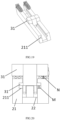
FIG. 19 is a schematic structural view of a fifth embodiment of the present application; and -
FIG. 20 is a front view ofFIG. 19 . -
- 1: rear roller;
- 2: sliding rail; 21: protruding guide block; 22: slideway; 23: groove; 24: climbing boss; 25: platform; 26: protruding stopper;
- M: the farthest distance between the support component and a lower side wall of the anti-detachment concave rail after the support component is inserted into the anti-detachment concave rails;
- N: the farthest distance between the support component and a top surface of the protruding guide block after the support component is inserted into the anti-detachment concave rails;
- 3: working component; 31: support component; 32: buckle;
- 4: front roller;
- 5: damping device;
- 6: sensor;
- 7: cabinet; 71: slot.
- Preferred embodiments of the present application will be described below with reference to the accompanying drawings. It should be understood by those skilled in the art that these embodiments are only used to explain the technical principle of the present application, and are not intended to limit the scope of protection of the present application. These embodiments can be adjusted by those skilled in the art as needed to adapt to specific application scenes. For example, although the description is given in the specification by taking the first movement component as the rear roller, the present application can obviously adopt other forms of movement components, such as a sliding component which can be implemented through a slider, as long as the movement device enables the working component to slide in and out, and after the movement device moves to the groove, the support component can support part or all of the gravity of the working component.
- It should be noted that in the description of the present application, terms indicating directional or positional relationships, such as "upper", "lower", "vertical", "horizontal" and the like, are based on the directional or positional relationships shown in the accompanying drawings. They are only used for ease of description, and do not indicate or imply that the device or element must have a specific orientation, or must be constructed or operated in a specific orientation; therefore, they should not be considered as limitations to the present application. In addition, terms "first" and "second" are only used for descriptive purpose, and should not be understood as indicating or implying relative importance.
- In addition, it should also be noted that in the description of the present application, unless otherwise clearly specified and defined, terms "install", "connect" and "connection" should be understood in a broad sense; for example, the connection may be a fixed connection, or a detachable connection, or an integral connection; it may be a mechanical connection, or an electrical connection; it may be a direct connection, or an indirect connection implemented through an intermediate medium. For those skilled in the art, the specific meaning of the above terms in the present application can be interpreted according to specific situations.
- Firstly, with reference to
FIGS. 1-15 , a specific preferred embodiment of the present application will be described. - Referring to
FIGS. 1-15 , the present application proposes a clothing treatment apparatus, which includes a first movement component, a second movement component, and a pull-out workingcomponent 3. The second movement component is provided with agroove 23. Specifically, in the first embodiment of the present application, the first movement component may be arear roller 1, and the second movement component may be a slidingrail 2. In a possible embodiment, the solution of the slidingrail 2 may be the slidingrail 2 with protruding guide blocks 21 arranged on both sides and aslideway 22 arranged in the middle, as shown inFIGS. 2 and11 . Correspondingly, thegroove 23 is arranged on a rear side of theslideway 22 to match with the first movement component. - The working
component 3 can be a pull-out type pulsator washing machine, which can be directly slidably arranged on the slidingrail 2; alternatively, as shown inFIG. 2 , the pulsator washing machine can be placed in a box (FIG. 2 only shows the box, and the body of the pulsator washing machine is not shown), and then slidably arranged on the sliding rail. - Next, reference is made to
FIGS. 6, 7 , and8 , asupport component 31 is provided below the workingcomponent 3, and therear roller 1 of the first movement component is also provided on the workingcomponent 3. In a preferred solution, therear roller 1 is indirectly arranged on the workingcomponent 3 by placing it on thesupport component 31, as shown inFIG. 7 . - Through the above structure, in the clothing treatment apparatus of the present application, the
rear roller 1 can drive the workingcomponent 3 to move on the slidingrail 2 during the pulling process of the workingcomponent 3; after the workingcomponent 3 reaches a working position, therear roller 1 moves to thegroove 23, as shown inFIG. 9 orFIG. 10 , so that therear roller 1 does not support the gravity of the workingcomponent 3 or supports part of the gravity of the workingcomponent 3, and thesupport component 31 supports the remaining part of the gravity of the workingcomponent 3. There are two situations for this. If therear roller 1 directly falls into thegroove 23 completely and is suspended, at this time, thesupport component 31 will fully bear the gravity of the workingcomponent 3. If therear roller 1 is provided with an elastic structure such as an elastic member like a spring arranged above therear roller 1, as shown inFIG. 14 , then therear roller 1 can still provide certain support after abutting a bottom surface of thegroove 23; at this time, thesupport component 31 plays a role in supporting the remaining part of the gravity of the workingcomponent 3. - In a preferred solution of the first embodiment, as shown in
FIGS. 2 ,6-8 and11 , support positions of thesupport component 31 in the above solution can be located on the protruding guide blocks 21 on both sides of the slidingrail 2, in which thesupport component 31 abuts against the protruding guide blocks 21 to transmit the force to the slidingrail 2. Of course, thesupport component 31 and the slidingrail 2 can also be staggered so that the force is directly transmitted to a bottom surface of a cabinet 7 (this solution is not shown in the drawings), or if the clothing treatment apparatus does not have thecabinet 7, the force can also be directly transmitted to the ground or an installation platform (this solution is not shown in the drawings). - Through the above structural design, the present application enables the
rear roller 1 to fall into thegroove 23 after the workingcomponent 3 is pulled out to put the clothing in and pushed back to the working position, so that thesupport component 31 supports the majority of the force, and therear roller 1 no longer bears the eccentric force of the washing machine during the washing and vibrating process, that is, therear roller 1 no longer bears the horizontal force, which is in turn borne by thesupport component 31. In this way, the service life of therear roller 1 can be greatly extended. Moreover, due to the presence of thesupport component 31, the washing machine can also be supported more stably and firmly during the washing process, thus reducing the vibration frequency of the washing machine and reducing the overall vibration noise of the clothing treatment apparatus. Preferably, thesupport component 31 is a support block shown inFIG. 7 ; a bottom surface of the support block can be configured as a surface with a higher coefficient of friction, or the support block is overall made of a material with higher friction, such as rubber, further preventing thesupport component 31 from slipping or vibrating and displacing. - Preferably, in the first embodiment, as shown in
FIG. 6 , the clothing treatment apparatus of the present application is further provided with afront roller 4, which is arranged on a front side of the workingcomponent 3 and which is arranged to be capable of contacting with the ground to achieve support at a front end during the pulling process. Therefore, the overall structure does not rely entirely on the sliding rail to complete, and part of the force can be distributed to thefront roller 4. - In the first embodiment, as shown in
FIGS. 8 and14 , a dampingdevice 5 is also provided on a rear side of therear roller 1. The dampingdevice 5 is preferably a spring; of course, it can also adopt other damping structures, such as a damping rod or an elastic block, so as to avoid excessive force after pushing in, which may cause therear roller 1 to detach from the groove and continue to move backward and collide with thecabinet 7. - In the first embodiment, as shown in
FIG. 14 , asensor 6 capable of detecting whether therear roller 1 has stopped in place is also provided on an inner side of thegroove 23. Preferably, the structure that can be extended and retracted up and down of therear roller 1 can not only provide part of support force as described above, but also can prevent therear roller 1 from being suspended, so that therear roller 1 at least partially abuts against thesensor 6, avoiding failure of detection of thesensor 6 and improving the detection accuracy of thesensor 6. The steps of clothing treatment are started after the clothing treatment apparatus detects that the workingcomponent 3 is installed in place, so as to avoid accidental situations. - In the first embodiment, as shown in
FIG. 15 , the workingcomponent 3 is also provided with aninsertable buckle 32, and the clothing treatment apparatus further includes acabinet 7 on which aslot 71 that matches with thebuckle 32 is provided. Thebuckle 32 is arranged such that it can move toward theslot 71 during the process of the workingcomponent 3 entering the working position, and can be inserted into theslot 71 after the workingcomponent 3 enters the working position. This insertion snap-fit connection solution is highly suitable for the solution of the present application, so that once the workingcomponent 3 is pushed into the working position in the present application, it can be locked; the function of unlocking first is achieved during the process of pulling out the handle, and the pushing and pulling action is also coordinated with the opening and closing of the lock. Users only need one action to achieve the opening and pulling-out actions, as well as closing and pushing-in actions. - In the first embodiment, as shown in
FIG. 9 , the slidingrail 2 can be parallel to the horizontal plane. At this time, after the workingcomponent 3 is pushed in, a certain inclination may be formed since therear roller 1 has entered thegroove 23; but this is also within the allowable range of the working state of the workingcomponent 3 of the present application, and it can still work normally. - The solution of the second embodiment is overall the same as the first embodiment with the following difference therebetween: at the same time of achieving stable support for the working
component 3 as in the first embodiment, horizontal placement of the workingcomponent 3 is also achieved; as shown inFIG. 10 , in a more preferred embodiment, an operating side of the clothing treatment apparatus is a front side, and there is a height difference between front and rear sides of the second movement component (the sliding rail 2). Preferably, a height of the rear side is higher than that of the front side. Through the design of the height difference, the workingcomponent 3 can have an appropriate climbing action during the pushing-in process; then after therear roller 1 falls into thegroove 23, the overall flatness of the workingcomponent 3 can be achieved, making the working state of the workingcomponent 3 more stable. The service life is longer, and it is less likely to splash washing water during the operation. - Next, reference is made to
FIGS. 16 and 17 , the third embodiment differs from the first and second embodiments in that a climbingboss 24 is provided on the front side of thegroove 23 on the slidingrail 2 in the third embodiment, and correspondingly, twoplatforms 25 are also provided on the protruding guide blocks 21. This design makes the slidingrail 2 still be overall horizontal. The horizontal slidingrail 2 is a standard part with a lower purchase price, and there is no need to fabricate it into an inclined non-standard part. At this time, therear roller 1 first passes over the climbingboss 24, and then during the process of therear roller 1 falling into thegroove 23, thesupport component 31 directly falls onto theplatforms 25. At this time, it can also ensure that the workingcomponent 3 is overall placed horizontally during the operation, while also saving the cost. Preferably, the slidingrail 2 and the climbingboss 24 can be fixedly connected separately, or integrally formed; the protruding guide blocks 21 and theplatforms 25 can be fixedly connected separately, or integrally formed. - In the first embodiment, there is still a certain deficiency in limiting the position of the
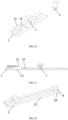
front roller 4. In order to make up for this defect, the present application also proposes a fourth embodiment. Referring toFIG. 18 , two protruding stoppers 26 are also provided on the front side of the protruding guide blocks 21. When the workingcomponent 3 reaches the working position, thefront roller 4 can be clamped between the two protruding stoppers 26, so that thefront roller 4 no longer has a swinging state, and the overall clothing treatment apparatus is fixed more firmly. Preferably, as shown inFIG. 18 , the protruding stoppers 26 are integrally formed with the protruding guide blocks 21, that is, the protruding stoppers 26 are protruding parts of the protruding guide blocks 21. - As shown in
FIGS. 19 and 20 , in some extreme situations, such as when the user pulls the workingcomponent 3 vertically upward instead of pulling it horizontally, it is very likely to cause the slidingrail 2 to detach from therear roller 4, resulting in the inability to slide and making the product fail to continue its operation. In order to avoid such extreme situations, in a fifth embodiment of the present application which is based on the first embodiment, anti-detachmentconcave rails 211 are designed on inner side walls of the protruding guide blocks 21. Two ends of thesupport component 31 are inserted into the anti-detachmentconcave rails 211. When therear roller 4 moves to thegroove 23, thesupport component 31 can bear the remaining part of the gravity of the working component. At this time, as shown inFIG. 17 , there may be two situations. In one situation, the farthest distance M between thesupport component 31 and a lower side wall of the anti-detachmentconcave rail 211 after thesupport component 31 is inserted into the anti-detachmentconcave rails 211 is smaller than the farthest distance N between thesupport component 31 and a top surface of the protrudingguide block 21 after thesupport component 31 is inserted into the anti-detachmentconcave rails 211, that is, M<N; at this time, thesupport component 31 at M abuts against the lower side walls of the anti-detachment concave rails to provide support force. If M>N, thesupport component 31 at N provides the support force. If M=N, thesupport component 31 at both M and N provides the support force. Due to the presence of the gap M, therear roller 4 can also fall into thegroove 23 normally without being affected, so that the anti-detachmentconcave rails 211 only play a role in preventing detachment and do not affect the actual operating trajectory of the product. - In summary, through the design of the
support component 31 in combination with thegroove 23, the present application enables therear roller 1 to enter thegroove 23 when the working component moves to the working position, and then thesupport component 31 plays the main supporting role. The supporting method of the rolling friction between therear roller 1 and theslideway 22 is directly changed to the supporting method of the up-and-down stacking between thesupport component 31 and the protruding guide blocks 21. When the clothing is taken out after use, the workingcomponent 3 can be pulled out with a slight force, and therear roller 1 can climb out of thegroove 23 so that the rolling friction is restored, making it still very effortless for the user to push and pull. This seamless switching not only protects therear roller 1 and reduces the noise generated by the workingcomponent 3 during operation, but also takes care of users, making it still very effortless for the user to push and pull. By making simple structural modifications to simply add the structures of thesupport component 31 and the groove, a fundamental switch and change in the movement mode is made on the basis of the original solution, which greatly improves the stability of the product on the basis of not increasing the cost of the clothing treatment apparatus of the present application, that is, the service life of therear roller 1 is extended, and user satisfaction is also improved, meaning lower vibration noise during use. In addition, the present application also proposes a design of height difference between the front and rear sides of the slidingrail 2, which further improves the stability of product during use and also reduces the probability of water leakage and the like caused by the tilting of the workingcomponent 3. The design of thesensor 6 also ensures that washing, drying and other operations can be performed only after the workingcomponent 3 reaches the working position, ensuring the safety of the product. - It should be noted that the above embodiments are only used to illustrate the principle of the present application and are not intended to limit the scope of protection of the present application. Without departing from the principle of the present application, those skilled in the art can adjust the above structures so that the present application can be applied to more specific application scenes.
- For example, although only one way of movement is provided for the first movement component, it is obviously not limited to the form of the
rear roller 1. For example, in an alternative embodiment, the first movement component can also be a sliding device, which is arranged to be capable of sliding into or out of thegroove 23. Preferably, the sliding device can be a slider with rounded corners on the side edges. For example, a cylindrical surface of a semi cylinder-shaped slider abuts against theslideway 22, and a flat surface of the semi cylinder-shaped slider is fixed to the bottom surface of the workingcomponent 3 to achieve the sliding connection between the first movement component and theslideway 22. These extensions based on the main inventive concept of the present application do not deviate from the principle of the present application and therefore will all fall within the scope of protection of the present application. - For example, in another alternative embodiment, the sliding
rail 2 is obviously not limited to the slidingrail 2 with the protruding guide blocks 21 arranged on both sides and theslideway 22 arranged in the middle as shown inFIG. 11 , and it can also be a slidingrail 2 with a protrudingguide block 21 arranged on an outer side and aslideway 22 arranged on an inner side as shown inFIG. 12 . Thegroove 23 is arranged on theslideway 22 on the inner side, and thesupport component 31 is arranged to be capable of abutting against the protrudingguide block 21 when the first movement component moves to thegroove 23. The above solution can also adapt to the structure of thesupport component 31 and thegroove 23 proposed by the present application without deviating from the principle of the present application, and therefore will fall within the scope of protection of the present application. - For example, in another alternative embodiment, the sliding
rail 2 is obviously not limited to the slidingrail 2 with the protruding guide blocks 21 arranged on both sides and theslideway 22 arranged in the middle as shown inFIG. 11 , and it can also be a slidingrail 2 with a protrudingguide block 21 arranged on an inner side and aslideway 22 arranged on an outer side as shown inFIG. 13 . Thegroove 23 is arranged on theslideway 22 on the outer side, and thesupport component 31 is arranged to be capable of abutting against the protrudingguide block 21 when the first movement component moves to thegroove 23. The above solution can also adapt to the structure of thesupport component 31 and thegroove 23 proposed by the present application without deviating from the principle of the present application, and therefore will fall within the scope of protection of the present application. - Finally, it should be noted that although the present application is described using a pull-out washing machine as an example, the solutions of the present application can obviously also be applied to other clothing treatment apparatuses. For example, they can also be applied to shoe washing machines, dryers, etc.
- Hitherto, the technical solutions of the present application have been described in connection with the preferred embodiments shown in the accompanying drawings, but it is easily understood by those skilled in the art that the scope of protection of the present application is obviously not limited to these specific embodiments. Without deviating from the principle of the present application, those skilled in the art can make equivalent changes or replacements to relevant technical features, and all the technical solutions after these changes or replacements will fall within the scope of protection of the present application.
Claims (44)
- A clothing treatment apparatus, wherein the clothing treatment apparatus comprises a first movement component, a second movement component, and a pull-out working component;the second movement component is a sliding rail, which is provided with a groove and a climbing boss that are adjacent to each other, and platforms are also provided on the sides of the sliding rail;the working component is provided with a support component, and the first movement component is provided on the working component;the clothing treatment apparatus is arranged such that during the pulling-out process of the working component, the first movement component can drive the working component to move on the second movement component, and after the working component reaches a working position, the first movement component can move to the groove after it finishes climbing the climbing boss, so that the first movement component does not support the gravity of the working component or supports part of the gravity of the working component, and the support component abuts against the platforms, thereby supporting the remaining part of the gravity of the working component.
- The clothing treatment apparatus according to claim 1, wherein the second movement component is a sliding rail with protruding guide blocks arranged on both sides and a slideway arranged in the middle; the groove and the climbing boss are arranged on the middle slideway, the platforms are arranged on the protruding guide blocks, and the support component is arranged to be capable of abutting against the platforms when the first movement component moves to the groove.
- The clothing treatment apparatus according to claim 2, wherein an operating side of the clothing treatment apparatus is a front side, and there is a height difference between front and rear sides of the second movement component.
- The clothing treatment apparatus according to claim 2, wherein the first movement component is a rear roller, and correspondingly, the groove and the platforms are arranged on a rear side of the slideway.
- The clothing treatment apparatus according to claim 4, wherein the clothing treatment apparatus further comprises a front roller, which is arranged on a front side of the working component and is arranged to be capable of abutting against the ground.
- The clothing treatment apparatus according to claim 2, wherein the first movement component is a sliding device, which is arranged to be capable of sliding into or out of the groove.
- The clothing treatment apparatus according to claim 6, wherein the sliding device is a slider with rounded corners on the side edges.
- The clothing treatment apparatus according to claim 1, wherein a damping device is also provided on a rear side of the second movement component.
- The clothing treatment apparatus according to claim 8, wherein the damping device is a spring.
- The clothing treatment apparatus according to claim 1, wherein the second movement component is a sliding rail with a protruding guide block arranged on an outer side and a slideway arranged on an inner side; the groove and the climbing boss are arranged on the slideway on the inner side, the platform is arranged on the protruding guide block, and the support component is arranged to be capable of abutting against the platform when the first movement component moves to the groove.
- The clothing treatment apparatus according to claim 1, wherein the second movement component is a sliding rail with a protruding guide block arranged on an inner side and a slideway arranged on an outer side; the groove and the climbing boss are arranged on the slideway on the outer side, the platform is arranged on the protruding guide block, and the support component is arranged to be capable of abutting against the platform when the first movement component moves to the groove.
- The clothing treatment apparatus according to claim 1, wherein a sensor capable of detecting whether the first movement component has stopped in place is also provided on an inner side of the groove.
- The clothing treatment apparatus according to claim 12, wherein the first movement component is a structure that can be extended and retracted up and down, so that the sensor can be triggered when the first movement component moves to the groove.
- The clothing treatment apparatus according to claim 1, wherein an insertable buckle is also provided on the working component, and the clothing treatment apparatus also comprises a cabinet on which a slot matching with the buckle is provided; the buckle is arranged such that it can move toward the slot during the process of the working component entering the working position, and can be inserted into the slot after the working component enters the working position.
- The clothing treatment apparatus according to claim 1, wherein the support component is a support block.
- The clothing treatment apparatus according to any one of claims 2, 10 and 11, wherein the protruding guide blocks are integrally formed with the platforms.
- The clothing treatment apparatus according to claim 3, wherein a height of the rear side of the second movement component is higher than a height of the front side of the second movement component.
- A clothing treatment apparatus, wherein the clothing treatment apparatus comprises a first movement component, a second movement component, and a pull-out working component;the second movement component is provided with a groove;the working component is provided with a support component, and the first movement component is provided on the working component;the clothing treatment apparatus is arranged such that during the pulling-out process of the working component, the first movement component can drive the working component to move on the second movement component, and after the working component reaches a working position, the first movement component can move to the groove, so that the first movement component does not support the gravity of the working component or supports part of the gravity of the working component, and the support component supports the remaining part of the gravity of the working component;the second movement component is a sliding rail with protruding guide blocks arranged on both sides and a slideway arranged in the middle; the groove is arranged on the middle slideway, and the support component is arranged to be capable of abutting against the protruding guide blocks when the first movement component moves to the groove;the clothing treatment apparatus also comprises a front roller, which is arranged on a front side of the working component and is arranged to be capable of abutting against the ground;front sides of the protruding guide blocks are also provided with two protruding stoppers, so that after the working component reaches the working position, the front roller is clamped between the two protruding stoppers.
- The clothing treatment apparatus according to claim 18, wherein an operating side of the clothing treatment apparatus is a front side, and there is a height difference between front and rear sides of the second movement component.
- The clothing treatment apparatus according to claim 18, wherein the first movement component is a rear roller, and correspondingly, the groove is arranged on a rear side of the slideway.
- The clothing treatment apparatus according to claim 18, wherein the first movement component is a sliding device, which is arranged to be capable of sliding into or out of the groove.
- The clothing treatment apparatus according to claim 21, wherein the sliding device is a slider with rounded corners on the side edges.
- The clothing treatment apparatus according to claim 18, wherein a damping device is also provided on a rear side of the second movement component.
- The clothing treatment apparatus according to claim 23, wherein the damping device is a spring.
- The clothing treatment apparatus according to claim 18, wherein a sensor capable of detecting whether the first movement component has stopped in place is also provided on an inner side of the groove.
- The clothing treatment apparatus according to claim 25, wherein the first movement component is a structure that can be extended and retracted up and down, so that the sensor can be triggered when the first movement component moves to the groove.
- The clothing treatment apparatus according to claim 18, wherein an insertable buckle is also provided on the working component, and the clothing treatment apparatus also comprises a cabinet on which a slot matching with the buckle is provided; the buckle is arranged such that it can move toward the slot during the process of the working component entering the working position, and can be inserted into the slot after the working component enters the working position.
- The clothing treatment apparatus according to claim 18, wherein the support component is a support block.
- The clothing treatment apparatus according to claim 18, wherein the protruding stoppers are integrally formed with the protruding guide blocks.
- The clothing treatment apparatus according to claim 19, wherein a height of the rear side of the second movement component is higher than a height of the front side of the second movement component.
- A clothing treatment apparatus, wherein the clothing treatment apparatus comprises a first movement component, a second movement component, and a pull-out working component;the second movement component is provided with a groove;the working component is provided with a support component, and the first movement component is provided on the working component;the clothing treatment apparatus is arranged such that during the pulling-out process of the working component, the first movement component can drive the working component to move on the second movement component, and after the working component reaches a working position, the first movement component can move to the groove, so that the first movement component does not support the gravity of the working component or supports part of the gravity of the working component, and the support component supports the remaining part of the gravity of the working component;the second movement component is a sliding rail with protruding guide blocks arranged on both sides and a slideway arranged in the middle; the groove is arranged on the middle slideway, and anti-detachment concave rails are also provided on inner side walls of the protruding guide blocks; andtwo ends of the support component are inserted into the anti-detachment concave rails, and when the first movement component moves to the groove, the support component can bear the remaining part of the gravity of the working component.
- The clothing treatment apparatus according to claim 31, wherein an opening size of the anti-detachment concave rail is larger than a thickness size of the anti-detachment protrusion.
- The clothing treatment apparatus according to claim 32, wherein an operating side of the clothing treatment apparatus is a front side, and there is a height difference between front and rear sides of the second movement component.
- The clothing treatment apparatus according to claim 32, wherein the first movement component is a rear roller, and correspondingly, the groove is arranged on a rear side of the slideway.
- The clothing treatment apparatus according to claim 34, wherein the clothing treatment apparatus also comprises a front roller, which is arranged on a front side of the working component and is arranged to be capable of abutting against the ground.
- The clothing treatment apparatus according to claim 32, wherein the first movement component is a sliding device, which is arranged to be capable of sliding into or out of the groove.
- The clothing treatment apparatus according to claim 36, wherein the sliding device is a slider with rounded corners on the side edges.
- The clothing treatment apparatus according to claim 31, wherein a damping device is also provided on a rear side of the second movement component.
- The clothing treatment apparatus according to claim 38, wherein the damping device is a spring.
- The clothing treatment apparatus according to claim 31, wherein a sensor capable of detecting whether the first movement component has stopped in place is also provided on an inner side of the groove.
- The clothing treatment apparatus according to claim 40, wherein the first movement component is a structure that can be extended and retracted up and down, so that the sensor can be triggered when the first movement component moves to the groove.
- The clothing treatment apparatus according to claim 31, wherein an insertable buckle is also provided on the working component, and the clothing treatment apparatus also comprises a cabinet on which a slot matching with the buckle is provided; the buckle is arranged such that it can move toward the slot during the process of the working component entering the working position, and can be inserted into the slot after the working component enters the working position.
- The clothing treatment apparatus according to claim 31, wherein the support component is a support block.
- The clothing treatment apparatus according to claim 33, wherein a height of the rear side of the second movement component is higher than a height of the front side of the second movement component.
Applications Claiming Priority (4)
| Application Number | Priority Date | Filing Date | Title |
|---|---|---|---|
| CN202210908305.7A CN117512954A (en) | 2022-07-29 | 2022-07-29 | Laundry treatment equipment |
| CN202210908304.2A CN117512953A (en) | 2022-07-29 | 2022-07-29 | Laundry treatment equipment |
| CN202210910795.4A CN117512957A (en) | 2022-07-29 | 2022-07-29 | Laundry treatment equipment |
| PCT/CN2023/098206 WO2024021864A1 (en) | 2022-07-29 | 2023-06-05 | Clothes treatment apparatus |
Publications (2)
| Publication Number | Publication Date |
|---|---|
| EP4563738A1 true EP4563738A1 (en) | 2025-06-04 |
| EP4563738A4 EP4563738A4 (en) | 2025-10-29 |
Family
ID=89705331
Family Applications (1)
| Application Number | Title | Priority Date | Filing Date |
|---|---|---|---|
| EP23845077.9A Pending EP4563738A4 (en) | 2022-07-29 | 2023-06-05 | DEVICE FOR THE TREATMENT OF GARMENTS |
Country Status (5)
| Country | Link |
|---|---|
| US (1) | US20260043190A1 (en) |
| EP (1) | EP4563738A4 (en) |
| JP (1) | JP2025524098A (en) |
| AU (1) | AU2023315588B2 (en) |
| WO (1) | WO2024021864A1 (en) |
Family Cites Families (21)
| Publication number | Priority date | Publication date | Assignee | Title |
|---|---|---|---|---|
| JPS4844065U (en) * | 1971-09-23 | 1973-06-08 | ||
| JPS5534069Y2 (en) * | 1975-01-23 | 1980-08-12 | ||
| JPS5886763U (en) * | 1981-12-03 | 1983-06-13 | 谷沢 實太郎 | Folding chair storage trolley storage device |
| AT407474B (en) * | 1996-12-18 | 2001-03-26 | Fulterer Gmbh | EXTENSION GUIDE FOR DRAWERS OR THE LIKE |
| KR100222986B1 (en) * | 1997-08-12 | 1999-10-01 | 윤종용 | Drawer type receipt device of a refrigerator |
| KR20020006807A (en) * | 2000-07-13 | 2002-01-26 | 윤종용 | Built-in type washing machine |
| KR100437778B1 (en) * | 2001-10-15 | 2004-06-30 | 엘지전자 주식회사 | Safety device of cabinet for drawer type washing machine |
| JP2004256999A (en) * | 2003-02-24 | 2004-09-16 | Asahi Kasei Homes Kk | Waterproof pan for washer |
| DE102010039647A1 (en) * | 2010-08-23 | 2012-02-23 | BSH Bosch und Siemens Hausgeräte GmbH | Refrigerating appliance with an extendable refrigerated goods container |
| DE102010039644A1 (en) * | 2010-08-23 | 2012-02-23 | BSH Bosch und Siemens Hausgeräte GmbH | Refrigerating appliance with an extendable refrigerated goods container |
| CN102147184B (en) * | 2011-04-13 | 2013-04-17 | 合肥美的荣事达电冰箱有限公司 | Drawer component for refrigerating plant and refrigerating plant comprising same |
| CN105624964B (en) * | 2014-10-30 | 2019-08-27 | 青岛海尔洗衣机有限公司 | A drawer type washing device |
| JP2021053274A (en) * | 2019-10-01 | 2021-04-08 | リンナイ株式会社 | Dishwasher |
| CN113774631B (en) * | 2020-05-20 | 2023-11-10 | 佛山市顺德海尔电器有限公司 | a washing machine |
| CN114075764A (en) * | 2020-08-20 | 2022-02-22 | 青岛海尔洗衣机有限公司 | Clothes treating apparatus |
| CN214692823U (en) * | 2021-04-12 | 2021-11-12 | 海南湘菱电梯工程有限公司 | Elevator layer door anticreep device |
| CN218372879U (en) * | 2022-07-29 | 2023-01-24 | 青岛海尔洗涤电器有限公司 | Clothes treating apparatus |
| CN218666792U (en) * | 2022-07-29 | 2023-03-21 | 青岛海尔洗涤电器有限公司 | Clothes treating apparatus |
| CN218372882U (en) * | 2022-07-29 | 2023-01-24 | 青岛海尔洗涤电器有限公司 | Clothes treating apparatus |
| CN218372880U (en) * | 2022-07-29 | 2023-01-24 | 青岛海尔洗涤电器有限公司 | Clothes treating apparatus |
| CN218345726U (en) * | 2022-07-29 | 2023-01-20 | 青岛海尔洗涤电器有限公司 | Clothes treating apparatus |
-
2023
- 2023-06-05 US US19/099,133 patent/US20260043190A1/en active Pending
- 2023-06-05 EP EP23845077.9A patent/EP4563738A4/en active Pending
- 2023-06-05 AU AU2023315588A patent/AU2023315588B2/en active Active
- 2023-06-05 WO PCT/CN2023/098206 patent/WO2024021864A1/en not_active Ceased
- 2023-06-05 JP JP2025504251A patent/JP2025524098A/en active Pending
Also Published As
| Publication number | Publication date |
|---|---|
| EP4563738A4 (en) | 2025-10-29 |
| JP2025524098A (en) | 2025-07-25 |
| WO2024021864A1 (en) | 2024-02-01 |
| AU2023315588A1 (en) | 2025-02-13 |
| AU2023315588B2 (en) | 2026-06-18 |
| US20260043190A1 (en) | 2026-02-12 |
Similar Documents
| Publication | Publication Date | Title |
|---|---|---|
| CN219059472U (en) | Clothes processing equipment | |
| CN218711600U (en) | Clothes treating apparatus | |
| CN218711601U (en) | Clothes treating apparatus | |
| CN218711599U (en) | Clothes treating apparatus | |
| CN218372880U (en) | Clothes treating apparatus | |
| CN218372882U (en) | Clothes treating apparatus | |
| CN218345726U (en) | Clothes treating apparatus | |
| CN218666794U (en) | Clothes treating apparatus | |
| CN218372879U (en) | Clothes treating apparatus | |
| CN218666792U (en) | Clothes treating apparatus | |
| KR20170015333A (en) | Sliding-pivoting mechanism of a shelf of a piece of furniture or of a domestic appliance, piece of furniture, and a domestic appliance | |
| US6390574B2 (en) | Fully extendible drawer unit and coupling | |
| CN218711598U (en) | Clothes treating apparatus | |
| CN218666793U (en) | Clothes treating apparatus | |
| KR20170016366A (en) | Sliding-pivoting mechanism of a shelf of a piece of furniture or of a domestic appliance, piece of furniture, and domestic appliance | |
| EP4563739A1 (en) | Laundry treatment apparatus | |
| CN218345725U (en) | Clothes treating apparatus | |
| US20260043190A1 (en) | Clothes treatment apparatus | |
| CN117512953A (en) | Laundry treatment equipment | |
| CN117758482B (en) | Clothes treating apparatus | |
| CN117758481A (en) | Clothes treating apparatus | |
| CN117512957A (en) | Laundry treatment equipment | |
| CN219385692U (en) | Clothes treating apparatus | |
| WO2024055873A1 (en) | Clothing treatmeant apparatus | |
| CN117512954A (en) | Laundry treatment equipment |
Legal Events
| Date | Code | Title | Description |
|---|---|---|---|
| STAA | Information on the status of an ep patent application or granted ep patent |
Free format text: STATUS: THE INTERNATIONAL PUBLICATION HAS BEEN MADE |
|
| PUAI | Public reference made under article 153(3) epc to a published international application that has entered the european phase |
Free format text: ORIGINAL CODE: 0009012 |
|
| STAA | Information on the status of an ep patent application or granted ep patent |
Free format text: STATUS: REQUEST FOR EXAMINATION WAS MADE |
|
| 17P | Request for examination filed |
Effective date: 20250226 |
|
| AK | Designated contracting states |
Kind code of ref document: A1 Designated state(s): AL AT BE BG CH CY CZ DE DK EE ES FI FR GB GR HR HU IE IS IT LI LT LU LV MC ME MK MT NL NO PL PT RO RS SE SI SK SM TR |
|
| REG | Reference to a national code |
Ref country code: DE Ref legal event code: R079 Free format text: PREVIOUS MAIN CLASS: D06F0039120000 Ipc: D06F0031000000 |
|
| STAA | Information on the status of an ep patent application or granted ep patent |
Free format text: STATUS: EXAMINATION IS IN PROGRESS |
|
| A4 | Supplementary search report drawn up and despatched |
Effective date: 20250926 |
|
| RIC1 | Information provided on ipc code assigned before grant |
Ipc: D06F 31/00 20060101AFI20250922BHEP Ipc: D06F 39/12 20060101ALI20250922BHEP Ipc: D06F 23/04 20060101ALN20250922BHEP |
|
| DAV | Request for validation of the european patent (deleted) | ||
| DAX | Request for extension of the european patent (deleted) | ||
| 17Q | First examination report despatched |
Effective date: 20251010 |