EP4563735A1 - Air jet loom with weft insertion device - Google Patents
Air jet loom with weft insertion device Download PDFInfo
- Publication number
- EP4563735A1 EP4563735A1 EP24211090.6A EP24211090A EP4563735A1 EP 4563735 A1 EP4563735 A1 EP 4563735A1 EP 24211090 A EP24211090 A EP 24211090A EP 4563735 A1 EP4563735 A1 EP 4563735A1
- Authority
- EP
- European Patent Office
- Prior art keywords
- support member
- tank
- fixing holes
- pair
- electromagnetic
- Prior art date
- Legal status (The legal status is an assumption and is not a legal conclusion. Google has not performed a legal analysis and makes no representation as to the accuracy of the status listed.)
- Withdrawn
Links
Images




Classifications
-
- D—TEXTILES; PAPER
- D03—WEAVING
- D03D—WOVEN FABRICS; METHODS OF WEAVING; LOOMS
- D03D47/00—Looms in which bulk supply of weft does not pass through shed, e.g. shuttleless looms, gripper shuttle looms, dummy shuttle looms
- D03D47/28—Looms in which bulk supply of weft does not pass through shed, e.g. shuttleless looms, gripper shuttle looms, dummy shuttle looms wherein the weft itself is projected into the shed
- D03D47/30—Looms in which bulk supply of weft does not pass through shed, e.g. shuttleless looms, gripper shuttle looms, dummy shuttle looms wherein the weft itself is projected into the shed by gas jet
- D03D47/3026—Air supply systems
- D03D47/306—Construction or details of parts, e.g. valves, ducts
-
- D—TEXTILES; PAPER
- D03—WEAVING
- D03D—WOVEN FABRICS; METHODS OF WEAVING; LOOMS
- D03D47/00—Looms in which bulk supply of weft does not pass through shed, e.g. shuttleless looms, gripper shuttle looms, dummy shuttle looms
- D03D47/28—Looms in which bulk supply of weft does not pass through shed, e.g. shuttleless looms, gripper shuttle looms, dummy shuttle looms wherein the weft itself is projected into the shed
- D03D47/30—Looms in which bulk supply of weft does not pass through shed, e.g. shuttleless looms, gripper shuttle looms, dummy shuttle looms wherein the weft itself is projected into the shed by gas jet
- D03D47/3026—Air supply systems
- D03D47/3033—Controlling the air supply
- D03D47/304—Controlling of the air supply to the auxiliary nozzles
-
- D—TEXTILES; PAPER
- D03—WEAVING
- D03D—WOVEN FABRICS; METHODS OF WEAVING; LOOMS
- D03D47/00—Looms in which bulk supply of weft does not pass through shed, e.g. shuttleless looms, gripper shuttle looms, dummy shuttle looms
- D03D47/28—Looms in which bulk supply of weft does not pass through shed, e.g. shuttleless looms, gripper shuttle looms, dummy shuttle looms wherein the weft itself is projected into the shed
- D03D47/30—Looms in which bulk supply of weft does not pass through shed, e.g. shuttleless looms, gripper shuttle looms, dummy shuttle looms wherein the weft itself is projected into the shed by gas jet
- D03D47/3026—Air supply systems
- D03D47/3053—Arrangements or lay out of air supply systems
Definitions
- the present invention relates to a weft insertion device of an air jet loom.
- Japanese Patent Application Publication No. 2003-239160 discloses a weft insertion device of a jet loom, which is an air jet loom.
- the weft insertion device of the jet loom includes an air tank, a plurality of auxiliary weft insertion nozzles corresponding to a plurality of sub-nozzles, a plurality of electromagnetic on-off valves, and a plurality of pipes.
- An inlet port is formed in each of the electromagnetic on-off valves.
- Outlet ports corresponding to tank holes are formed in the air tank.
- the electromagnetic on-off valves are arranged in line in the weft insertion direction for a weft yarn.
- the electromagnetic on-off valves are attached to the air tank with the inlet ports directly connected to the tank holes.
- the sub-nozzles are connected, as one group, to the air tank via one electromagnetic on-off valve.
- the sub-nozzles are arranged in line in the weft insertion direction for a weft yarn. Air is supplied to the sub-nozzles from the air tank via the pipes and the electromagnetic on-off valves.
- the weft insertion device inserts the weft yarn by air jetting action from the sub-nozzles.
- a weft insertion device of an air jet loom in which a weft yarn is inserted into a reed passage by a main nozzle.
- the weft insertion device includes a plurality of sub-nozzles arranged in a weft insertion direction in which the weft yarn is inserted, and configured to discharge compressed air to the weft yarn inserted into the reed passage, an air tank in which the compressed air to be discharged from the sub-nozzles is stored, and having a plurality of tank holes arranged in the weft insertion direction, a plurality of electromagnetic on-off valves arranged in the weft insertion direction, having an inlet port from which the compressed air flows in, and configured to control supply of the compressed air from the air tank to the sub-nozzles, and a support member attached to the air tank, and supporting the electromagnetic on-off valves,
- the support member has a tank connection port in communication with one of the tank holes, and a plurality
- an air jet loom 100 includes a pair of side frames 11, a rocking shaft 12, a sley 13, a profile reed 16, a main nozzle M, and a weft insertion device 20.
- the pair of side frames 11 is spaced from each other in a width direction W of the air jet loom 100.
- the rocking shaft 12 is mounted on the pair of side frames 11 so as to extend in the width direction W of the airjet loom 100. Opposite ends of the rocking shaft 12 in the extending direction thereof are supported by the side frames 11 so as to reciprocate and be rotatable.
- the rocking shaft 12 includes an arm 12a that extends above the air jet loom 100.
- the arm 12a is formed integrally with the rocking shaft 12.
- the sley 13 is supported on an upper end of the arm 12a.
- the sley 13 extends in the width direction W of the air jet loom 100.
- the sley 13 rotationally moves integrally with the rocking shaft 12.
- the profile reed 16 is supported by the sley 13. A lower end of the profile reed 16 is fixed to the sley 13.
- the profile reed 16 is formed of a plurality of dents 16a arranged in a row in the width direction W of the air jet loom 100. It is noted that only one of the plurality of dents 16a is illustrated in FIG. 2 .
- the dents 16a are arranged on the sley 13 at intervals in the width direction W of the air jet loom 100.
- a lower end of each of the dents 16a is fixed to the sley 13, so that the dents 16a are supported by the sley 13.
- the profile reed 16 has a reed passage 16b.
- the reed passage 16b extends in the width direction W of the air jet loom 100. That is, the reed passage 16b extends in a direction in which the dents 16a are arranged.
- the reed passage 16b is opened at opposite ends of the profile reed 16 in the direction in which the dents 16a are arranged.
- the main nozzle M is connected to a pressure supply source (not illustrated), and a weft yarn Y is ejected from the main nozzle M into the reed passage 16b.
- the weft yarn Y ejected into the reed passage 16b travels through the reed passage 16b in the width direction W of the air jet loom 100. That is, the air jet loom 100 inserts the weft yarn Y into the reed passage 16b by the main nozzle M.
- a direction in which the weft yarn Y ejected from the main nozzle M travels is defined as a weft insertion direction X.
- the weft insertion direction X coincides with the width direction W of the air jet loom 100.
- the reed passage 16b extends in the weft insertion direction X.
- the weft insertion device 20 includes an air tank 10, a plurality of sub-nozzles S, a plurality of support members 21, a plurality of electromagnetic on-off valves 22, and a plurality of flexible tubes 23.
- the air tank 10 has an elongated shape having a long side direction extending in the width direction W of the air jet loom 100, i.e., the weft insertion direction X. Opposite ends of the air tank 10 in the long side direction thereof are supported by the side frames 11. In other words, the air tank 10 is supported by the pair of side frames 11 and is mounted over the pair of side frames 11. The air tank 10 extends in the width direction W of the air jet loom 100 and functions as a beam of a fixedly provided loom frame.
- a tank chamber 10b is formed inside the air tank 10. Compressed air is supplied from the pressure supply source (not illustrated) to the air tank 10 and stored in the tank chamber 10b. That is, the air tank 10 stores compressed air.
- the air tank 10 has a plurality of tank holes 10a arranged in the long side direction of the air tank 10. That is, the plurality of tank holes 10a is formed in the air tank 10 in the weft insertion direction X. As illustrated in FIG. 4 , a pair of fourth fixing holes H4 is formed in the air tank 10 so that the fourth fixing holes H4 are disposed on opposite sides of each of the tank holes 10a in the weft insertion direction X.
- a side to which the profile reed 16 moves for beating is defined as a front
- a side to which the profile reed 16 returns after beating is defined as a rear. It can be said that the profile reed 16 rotationally moves in a front-rear direction F of the air jet loom 100.
- the sub-nozzles S are disposed between the profile reed 16 and the air tank 10 in the front-rear direction F of the air jet loom 100.
- the sub-nozzles S are arranged in the long side direction of the air tank 10. In other words, the sub-nozzles S are arranged in the weft insertion direction X.
- the sub-nozzles S are attached to the sley 13. That is, the sub-nozzles S are supported by the sley 13 so as to be rotationally movable integrally with the rocking shaft 12.
- a first end of each of the flexible tubes 23 is connected to its associated one of the sub-nozzles S.
- a second end of each of the flexible tubes 23 is connected to its associated one of the electromagnetic on-off valves 22.
- the electromagnetic on-off valves 22 are attached to the air tank 10 via the support members 21.
- the electromagnetic on-off valves 22 are arranged in line in the long side direction of the air tank 10. In other words, the electromagnetic on-off valves 22 are provided in the weft insertion direction X.
- the electromagnetic on-off valves 22 each have one inlet port 22a through which compressed air flows in, and two outlet ports 22b. That is, the electromagnetic on-off valves 22 each have the inlet port 22a through which compressed air flows in.
- the second end of each of the flexible tube 23 is connected to its associated one of the outlet ports 22b.
- Compressed air flowing into the electromagnetic on-off valves 22 through the inlet ports 22a via the support members 21, which will be described later passes through a valve passage 22c formed inside each of the electromagnetic on-off valves 22 and is discharged to its associated one of the flexible tubes 23 through its associated one of the outlet ports 22b.
- Compressed air is supplied to each of the electromagnetic on-off valves 22 through its associated inlet port 22a, and is discharged from its associated two sub-nozzles S via the valve passage 22c, the two outlet ports 22b, and the two flexible tubes 23.
- compressed air is supplied to the sub-nozzles S from the air tank 10 via the flexible tubes 23, the electromagnetic on-off valves 22, and the support members 21, which will be described later.
- Compressed air supplied from the air tank 10 is ejected from the sub-nozzles S.
- Compressed air is ejected from the sub-nozzles S into the reed passage 16b.
- the electromagnetic on-off valves 22 each are switchable between an energized state in which the inlet port 22a and the outlet ports 22b are in communication with each other, and a deenergized state in which the inlet port 22a and the outlet ports 22b are shut off from each other.
- the electromagnetic on-off valves 22 each are connected to a control device (not illustrated) and switched between the energized state and the deenergized state in response to a signal from the control device.
- the control device can control each of the electromagnetic on-off valves 22 individually. For example, the control device can set one of the plurality of electromagnetic on-off valves 22 to an energized state and the others of the electromagnetic on-off valves 22 to the deenergized state. That is, the electromagnetic on-off valves 22 control supply of compressed air from the air tank 10 to the sub-nozzles S.
- the electromagnetic on-off valves 22 each have a pair of first fixing holes H1.
- the first fixing holes H1 are opened at one surface of each of the electromagnetic on-off valves 22 on a side of the air tank 10 and at another surface that is a surface opposite to the one surface.
- the support members 21 each are interposed between the electromagnetic on-off valves 22 and the air tank 10.
- the support members 21 each have a plate shape that has a long side extending in the weft insertion direction X, and a thickness extending in the front-rear direction F.
- the support members 21 each have a plate shape that has a short side extending in an up-down direction U.
- the support members 21 each have a rectangular plate shape.
- a direction of the support member 21 that coincides with the front-rear direction F of the air jet loom 100 is referred to as a thickness direction T.
- the support member 21 has a tank side surface 31 and a valve side surface 32 opposite to the tank side surface 31 in the thickness direction T. That is, the support member 21 has a plate shape, and has the tank side surface 31 and the valve side surface 32 on opposite sides in the thickness direction T.
- the support member 21 has a first side surface 33, and a second side surface 34 that is a surface opposite to the first side surface 33 in the weft insertion direction X.
- the support member 21 is attached to the air tank 10 with the long side direction of the support member 21 coinciding with the weft insertion direction X.
- the weft insertion direction X of the support member 21 may be interpreted as the long side direction of the support member 21.
- the support member 21 is attached to the air tank 10 with the short side direction of the support member 21 coinciding with the up-down direction U.
- the up-down direction U of the support member 21 may be interpreted as the short side direction of the support member 21.
- the first side surface 33 is disposed on a side of the main nozzle M in the weft insertion direction X.
- the support member 21 has a lower surface 35 facing downward in the up-down direction U, which is a direction perpendicular to the thickness direction T and the weft insertion direction X, and an upper surface 36 facing upward and opposite to the lower surface 35.
- the support member 21 has a tank connection port 31a formed in the tank side surface 31. That is, the tank side surface 31 has the tank connection port 31a.
- the tank connection port 31a is formed in the center of the support member 21 in the weft insertion direction X and closer to the lower surface 35 in the up-down direction U.
- the support member 21 has a first valve connection port 321a and a second valve connection port 322a, which correspond to a plurality of valve connection ports, in the valve side surface 32. That is, the valve side surface 32 is a surface different from the tank side surface 31, and has the first valve connection port 321a and the second valve connection port 322a.
- the first valve connection port 321a is formed at a position closer to the first side surface 33 than the tank connection port 31a in the weft insertion direction X.
- the second valve connection port 322a is formed at a position closer to the second side surface 34 than the tank connection port 31a in the weft insertion direction X.
- the first valve connection port 321a and the second valve connection port 322a are formed at positions spaced from each other in the weft insertion direction X.
- the first valve connection port 321a and the second valve connection port 322a are formed closer to the upper surface 36 than the tank connection port 31a in the up-down direction U.
- the support member 21 is disposed at a position where the tank side surface 31 faces the air tank 10 and the tank connection port 31a is in communication with one of the plurality of tank holes 10a. That is, the support member 21 has the tank connection port 31a in communication with one of the tank holes 10a.
- a distance from the tank connection port 31a to the first valve connection port 321a in the weft insertion direction X is the same as a distance from the tank connection port 31a to the second valve connection port 322a.
- the support member 21 is disposed at a position where the valve side surface 32 faces the two electromagnetic on-off valves 22. Further, the support member 21 is disposed at a position where the inlet ports 22a of the two electromagnetic on-off valves 22 are in communication with the first valve connection port 321a and the second valve connection port 322a, respectively. That is, the support member 21 has the first valve connection port 321a and the second valve connection port 322a in communication with the inlet ports 22a.
- an internal flow passage 40 is formed in an inside of the support member 21, and connects the tank connection port 31a with the first valve connection port 321a and the second valve connection port 322a.
- the internal flow passage 40 has a first horizontal flow passage PX1, a second horizontal flow passage PX2, a first vertical flow passage PZ1, a second vertical flow passage PZ2, a third vertical flow passage PZ3, and a fourth vertical flow passage PZ4.
- the first horizontal flow passage PX1 extends in the weft insertion direction X, and is closed by closing members C at the first side surface 33 and the second side surface 34.
- the second horizontal flow passage PX2 extends in the weft insertion direction X, and is closed by closing members C at the first side surface 33 and the second side surface 34.
- the first horizontal flow passage PX1 and the second horizontal flow passage PX2 are arranged in this order from the lower surface 35 to the upper surface 36 in the up-down direction U.
- Each of the first to fourth vertical flow passages PZ1 to PZ4 extends in the up-down direction U, and is closed by the closing members C at the lower surface 35 and the upper surface 36.
- the first to fourth vertical flow passages PZ1 to PZ4 are arranged in the weft insertion direction X in order of the first vertical flow passage PZ1, the second vertical flow passage PZ2, the third vertical flow passage PZ3, and the fourth vertical flow passage PZ4 from the first side surface 33 to the second side surface 34.
- the second vertical flow passage PZ2 and the third vertical flow passage PZ3 are formed in a central portion of the support member 21 in the weft insertion direction X.
- the second vertical flow passage PZ2 and the third vertical flow passage PZ3 are slightly spaced from each other in the weft insertion direction X.
- the second vertical flow passage PZ2 and the third vertical flow passage PZ3 are disposed at positions overlapping the tank connection port 31a in the thickness direction T of the support member 21.
- the first vertical flow passage PZ1 is formed at a position spaced from the second vertical flow passage PZ2 on the first side surface 33 side in the weft insertion direction X.
- the first vertical flow passage PZ1 is disposed at a position overlapping the first valve connection port 321a in the thickness direction T of the support member 21.
- the fourth vertical flow passage PZ4 is formed at a position spaced from the third vertical flow passage PZ3 on the second side surface 34 side in the weft insertion direction X.
- the fourth vertical flow passage PZ4 is disposed at a position overlapping the second valve connection port 322a in the thickness direction T of the support member 21.
- a distance between the first vertical flow passage PZ1 and the second vertical flow passage PZ2 in the weft insertion direction X is the same as a distance between the third vertical flow passage PZ3 and the fourth vertical flow passage PZ4 in the weft insertion direction X.
- the first horizontal flow passage PX1 and the second horizontal flow passage PX2 are in communication with each other inside the support member 21 via the first to fourth vertical flow passages PY1 to PY4.
- the support member 21 has the internal flow passage 40 formed within a thickness of the support member 21.
- the second vertical flow passage PZ2 and the third vertical flow passage PZ3 are in communication with the tank connection port 31a. That is, the second vertical flow passage PZ2 and the third vertical flow passage PZ3 each are opened to the tank side surface 31 through the tank connection port 31a.
- the first vertical flow passage PZ1 is in communication with the first valve connection port 321a.
- the fourth vertical flow passage PZ4 is in communication with the second valve connection port 322a. That is, the first vertical flow passage PZ1 is opened at the valve side surface 32 via the first valve connection port 321a, and the fourth vertical flow passage PZ4 is opened at the valve side surface 32 via the second valve connection port 322a.
- the tank connection port 31a and the first valve connection port 321a are in communication with each other through the second vertical flow passage PZ2, the first horizontal flow passage PX1, the second horizontal flow passage PX2, and the first vertical flow passage PZ1.
- the tank connection port 31a and the second valve connection port 322a are in communication with each other through the third vertical flow passage PZ3, the first horizontal flow passage PX1, the second horizontal flow passage PX2, and the fourth vertical flow passage PZ4.
- the support member 21 has paired first valve fixing holes BH1 and paired second valve fixing holes BH2 each opened at the tank side surface 31 and the valve side surface 32.
- the paired first valve fixing holes BH1 and the paired second valve fixing holes BH2 each correspond to a pair of second fixing holes.
- the paired first valve fixing holes BH1 and the paired second valve fixing holes BH2 are formed side by side in the weft insertion direction X.
- the paired first valve fixing holes BH1 are formed in the support member 21 closer to the first side surface 33 than the central portion in the weft insertion direction X, and the paired second valve fixing holes BH2 is formed in the support member 21 closer to the second side surface 34 than the central portion in the weft insertion direction X.
- the paired first valve fixing holes BH1 are formed at positions at which the first valve connection port 321a is disposed between the paired first valve fixing holes BH1 in the weft insertion direction X of the support member 21.
- the paired first valve fixing holes BH1 face the pair of first fixing holes H1 in a state in which the electromagnetic on-off valves 22 and the support member 21 provide communication between the inlet port 22a and the first valve connection port 321a.
- a hole diameter of each of the paired first valve fixing holes BH1 is the same as that of each of the pair of first fixing holes H1 formed in each of the electromagnetic on-off valves 22.
- a pitch between the paired first valve fixing holes BH1 is the same as a pitch between the pair of first fixing holes H1. It is noted that the pitch between the paired first valve fixing holes BH1 corresponds to a distance between the centers of the paired first valve fixing holes BH1 in the weft insertion direction X. In addition, a pitch between the pair of first fixing holes H1 corresponds to a distance between the centers of the first fixing holes H1 in the weft insertion direction X.
- the paired second valve fixing holes BH2 are disposed at positions at which the second valve connection port 322a is disposed between the paired second valve fixing holes BH2 in the weft insertion direction X.
- the paired second valve fixing holes BH2 face the pair of first fixing holes H1 in a state in which the electromagnetic on-off valves 22 and the support member 21 provide communication between the inlet port 22a and the second valve connection port 322a.
- one electromagnetic on-off valve 22 having the inlet port 22a in communication with the paired second valve fixing holes BH2 is different from another electromagnetic on-off valve 22 having the inlet port 22a in communication with the paired first valve fixing holes BH1.
- a hole diameter of each of the paired second valve fixing holes BH2 is the same as that of each of the first fixing holes H1 formed in each of the electromagnetic on-off valves 22.
- the pitch between the paired second valve fixing holes BH2 is the same as the pitch between the first fixing holes H1.
- the pitch between the paired second valve fixing holes BH2 is a distance between the centers of the paired second valve fixing holes BH2 in the weft insertion direction X.
- the support member 21 has a pair of third fixing holes H3 that are opened at the tank side surface 31 and the valve side surface 32.
- the pair of third fixing holes H3 is formed at a central portion of the support member 21 in the weft insertion direction X.
- the third fixing holes H3 are disposed at positions at which the tank connection port 31a is disposed between the third fixing holes H3 in the weft insertion direction X.
- the third fixing holes H3 face the pair of fourth fixing holes H4 formed in the air tank 10 in a state in which the third fixing holes H3 provide communication between the tank hole 10a and the tank connection port 31a.
- a hole diameter of each of the third fixing holes H3 is the same as that of each of the fourth fixing holes H4.
- the pitch between the pair of third fixing holes H3 is the same as that between the pair of fourth fixing holes H4.
- the pitch between the pair of third fixing holes H3 is a distance between the centers of the third fixing holes H3 in the weft insertion direction X.
- the pitch between the pair of fourth fixing holes H4 is a distance between the centers of the fourth fixing holes H4 in the weft insertion direction X.
- the hole diameter of each of the paired first valve fixing holes BH1 is the same as that of each of the pair of third fixing holes H3. Further, the pitch between the paired first valve fixing holes BH1 is the same as the pitch between the pair of third fixing holes H3.
- the hole diameter of each of the paired second valve fixing holes BH2 is the same as that of each of the pair of third fixing holes H3. Further, the pitch between the paired second valve fixing holes BH2 is the same as the pitch between the pair of third fixing holes H3.
- the hole diameter of each of the first fixing holes H1, the hole diameter of each of the paired first valve fixing holes BH1, the hole diameter of each of the paired second valve fixing holes BH2, the hole diameter of each of the third fixing holes H3, and the hole diameter of each of the fourth fixing holes H4 are the same.
- the pitch between the pair of first fixing holes H1, the pitch between the paired first valve fixing holes BH1, the pitch between the paired second valve fixing holes BH2, the pitch between the pair of third fixing holes H3, and the pitch between the pair of fourth fixing holes H4 are the same.
- two electromagnetic on-off valves 22 are attached to the support member 21.
- Each of the two electromagnetic on-off valves 22 is fixed to the support member 21 by a pair of first fixing pins F1, which corresponds to valve fixing members.
- a first electromagnetic on-off valve 221, which is one of the two electromagnetic on-off valves 22, is provided at a position where the inlet port 22a is in communication with the first valve connection port 321a, and a second electromagnetic on-off valve 222, which is the other of the two electromagnetic on-off valves 22, is provided at a position where the inlet port 22a is in communication with the second valve connection port 322a.
- the first electromagnetic on-off valve 221 is fixed to the support member 21 with the first fixing pins F1 inserted into the pair of first fixing holes H1 and the paired first valve fixing holes BH1.
- the second electromagnetic on-off valve 222 is fixed to the support member 21 with the first fixing pins F1 inserted into the pair of first fixing holes H1 and the paired second valve fixing holes BH2. That is, the electromagnetic on-off valves 22 may be attached to the support member 21 with the first fixing pins F1 inserted through the pair of first fixing holes H1 and inserted into the paired first valve fixing holes BH1 and the paired second valve fixing holes BH2.
- first fixing pins F1 may be press-fitted into the paired first valve fixing holes BH1 and the paired second valve fixing holes BH2, or male threads of the first fixing pins F1 may be screwed into female threads of the paired first valve fixing holes BH1 and the paired second valve fixing holes BH2.
- the support member 21 to which the two electromagnetic on-off valves 22 are attached is fixed to the air tank 10 with a pair of second fixing pins F2, which corresponds to support fixing members.
- the pair of second fixing pins F2 are inserted through the pair of third fixing holes H3 and fixed to the pair of fourth fixing holes H4. That is, the support member 21 is attachable to the air tank 10 with the pair of second fixing pins F2 inserted through the third fixing holes H3 and inserted into the pair of fourth fixing holes H4. That is, the support member 21 is attached to the air tank 10 and supports the electromagnetic on-off valves 22.
- the second fixing pins F2 may be press-fitted into the fourth fixing holes H4, or male threads of the second fixing pins F2 may be screwed into female threads of the fourth fixing holes H4.
- the electromagnetic on-off valves 22 may be attached to the air tank 10 without using the support member 21.
- each of the electromagnetic on-off valves 22 is provided at a position where the inlet port 22a is in communication with the tank hole 10a, and the first fixing pins F1 inserted through the first fixing holes H1 are inserted into the fourth fixing holes H4.
- one electromagnetic on-off valve 22 can be connected to one tank hole 10a.
- the weft yarn Y is ejected from the main nozzle M and travels through the reed passage 16b in the weft insertion direction X.
- compressed air supplied from the air tank 10 is discharged from the plurality of sub-nozzles S of the weft insertion device 20.
- Discharge of air from the sub-nozzles S is performed as in a relay, i.e., relay air jet, from the main nozzle M side in the weft insertion direction X.
- the relay air jet propels the weft yarn Y ejected to into an opening of warp yarns TT.
- the relay air jet is performed by switching each of the electromagnetic on-off valves 22 between the energized state and the deenergized state by the control device (not illustrated). Compressed air is supplied to the sub-nozzles S via the support member 21, the electromagnetic on-off valves 22, and the flexible tubes 23.
- the weft yarn Y inserted by the weft insertion device 20 is beaten against a cloth fell N1 by the profile reed 16 which is rotationally moved by the rocking shaft 12.
- the weft yarn Y and the warp yarns TT form a woven fabric N.
- compressed air is discharged from the sub-nozzles S to the weft yarn Y inserted in the reed passage 16b.
- the sub-nozzles S are connected to their associated electromagnetic on-off valves 22.
- the electromagnetic on-off valves 22 control supply of compressed air from the air tank 10 to the sub-nozzles S.
- Compressed air is supplied to the electromagnetic on-off valves 22 from the air tank 10 via the internal flow passage 40 of the support member 21.
- Compressed air stored in the air tank 10 flows into the internal flow passages 40 of the support member 21 via the tank holes 10a and the tank connection ports 31a.
- Compressed air flowing through the internal flow passage 40 of the support member 21 is supplied to the electromagnetic on-off valves 22 via the first valve connection ports 321a and the second valve connection ports 322a. That is, the air tank 10 to which the support member 21 is attached supplies compressed air to the two electromagnetic on-off valves 22 through one tank hole 10a.
- the support member 21 may have a valve connection port in communication with the inlet port 22a of each of the electromagnetic on-off valves 22, in addition to the first valve connection port 321a and the second valve connection port 322a.
- the support member 21 has paired valve fixing holes different from the paired first valve fixing holes BH1 and the paired second valve fixing holes BH2.
- each of the third fixing holes H3 does not have to be the same as that of each of the fourth fixing holes H4, and the pitch between the third fixing holes H3 does not have to be the same as that between the fourth fixing holes H4.
- holes different from the pair of fourth fixing holes H4 are provided in the air tank 10.
- any one of the dimensions of the support member 21 in the thickness direction T, in the weft insertion direction X, and in the up-down direction U may be changed as appropriate.
- the support member 21 does not have to have a plate shape.
- the support member 21 may be configured such that the support member 21 can be disassembled.
- the support member 21 includes a first forming member A1 and a second forming member A2 aligned in the thickness direction T, a sealing member A3 that provides sealing between the first forming member A1 and the second forming member A2, and a plurality of connecting pins A4 for attaching the second forming member A2 to the first forming member A1.
- the support member 21 is formed by arranging the first forming member A1 and the second forming member A2 facing each other in the thickness direction T.
- the support member 21 has a tank side surface 31 on a surface of the first forming member A1 that is different from a surface facing the second forming member A2. That is, the first forming member A1 has the tank connection port 31a.
- the tank connection port 31a is opened at opposite surfaces of the first forming member A1 in the thickness direction thereof.
- the support member 21 has a valve side surface 32 on a surface of the second forming member A2 that is different from a surface facing the first forming member A1. That is, the second forming member A2 has the first valve connection port 321a and the second valve connection port 322a. Each of the first valve connection port 321a and the second valve connection port 322a is opened at opposite surfaces of the second forming member A2 in the thickness direction.
- a flow passage forming space A5 is formed in the support member 21.
- the flow passage forming space A5 has a first forming space A51 and a second forming space A52.
- the first forming space A51 is defined by a first defining portion A511 of the first forming member A1. That is, the first forming space A51 is formed in the first forming member A1.
- the first forming space A51 is recessed from a surface of the first forming member A1 facing the second forming member A2.
- the first forming space A51 is opened at the surface where the first defining portion A511 is formed, and in communication with the tank connection port 31a. That is, the first forming member A1 has the tank connection port 31a and the first forming space A51 in communication with the tank connection port 31a.
- the second forming space A52 is defined by a second defining portion A521 of the second forming member A2. That is, the second forming space A52 is formed in the second forming member A2.
- the second forming space A52 is recessed from a surface of the second forming member A2 facing the first forming member A1.
- the second forming space A52 is opened at the surface where the second defining portion A521 is formed, and in communication with the first valve connection port 321a and the second valve connection port 322a.
- the second forming member A2 has the first valve connection port 321a and the second valve connection port 322a, as well as the second forming space A52 in communication with the first valve connection port 321a and the second valve connection port 322a.
- the first forming member A1 and the second forming member A2 are connected by a plurality of connecting pins A4 so that the first forming space A51 and the second forming space A52 form the flow passage forming space A5.
- the tank connection port 31a is in communication with the first valve connection port 321a and the second valve connection port 322a via the flow passage forming space A5.
- the internal flow passage 40 is formed by the flow passage forming space A5.
- the second forming member A2 does not have to include the second defining portion A521 and the second forming space A52. In this case, the second forming member A2 closes the first forming space A51.
- the flow passage forming space A5 is formed in the first forming member A1. Therefore, the internal flow passage 40 is defined by closing the flow passage forming space A5 with the second forming member A2.
- the first forming member A1 does not have to include the first defining portion A511 and the first forming space A51. In this case, the first forming member A1 closes the second forming space A52.
- the flow passage forming space A5 is formed in the second forming member A2. Therefore, the internal flow passage 40 is defined by closing the flow passage forming space A5 with the first forming member A1.
- the flow passage forming space A5 is formed in at least one of the first forming member A1 and the second forming member A2, and the internal flow passage 40 is defined with the flow passage forming space A5 closed by at least the other of the first forming member A1 and the second forming member A2.
- the internal flow passage 40 is formed by the first forming member A1 and the second forming member A2.
- This configuration allows the internal flow passage to be formed more easily, as compared with a case where the internal flow passage is formed inside the support member 21 formed from a single member.
- the internal flow passage 40 having a rectangular cross-sectional shape may be formed, for example, by forming the flow passage forming space A5 as a recessed portion. As a result, a path and a cross-sectional shape of the internal flow passage 40 can be formed more easily, as compared with a case where the support member 21 is formed from a single member.
- the above configuration allows an inside of the support member 21 to be hollow that is opened at the tank connection port 31a, the first valve connection port 321a, and the second valve connection port 322a.
- the cross section of the internal flow passage 40 may be made larger, as compared with the case where the support member 21 is formed from a single member. As a result, the pressure loss of the compressed air in the internal flow passage 40 can be reduced.
- the support member 21 does not have to include only the tank side surface 31, the valve side surface 32, the first side surface 33, the second side surface 34, the lower surface 35, and the upper surface 36.
- the support member 21 may have an inclined surface D between the valve side surface 32 and the upper surface 36.
- the inclined surface D is inclined with respect to the valve side surface 32 and the upper surface 36 .
- the inclined surface D faces a direction in which the reed passage 16b is located as viewed from the support member 21 in the up-down direction U of the air jet loom 100.
- the first valve connection port 321a and the second valve connection port 322a are each formed in the inclined surface D. That is, the support member 21 has the inclined surface D facing the direction in which the reed passage 16b is located, and the electromagnetic on-off valves 22 are supported on the inclined surface D.
- the electromagnetic on-off valves 22 are disposed on the inclined surface D such that the inlet port 22a is in communication with and the first valve connection port 321a and the second valve connection port 322a.
- the internal flow passage 40 is bent inside the support member 21.
- the inclined surface D faces the reed passage 16b and thus faces the sub-nozzles S.
- the distance between the electromagnetic on-off valves 22 and the sub-nozzles S may be reduced and the electromagnetic on-off valves 22 may be oriented in a direction in which the sub-nozzles S are located.
- the distance for compressed air flowing between the electromagnetic on-off valves 22 and the sub-nozzles S may be shortened, and thus the pressure loss of compressed air occurring before it reaches the sub-nozzles S may be reduced.
- the support member 21 does not need to have the tank side surface 31 and the valve side surface 32 on opposite sides in the thickness direction T.
- the tank side surface 31 and the valve side surface 32 may face toward the air tank 10.
- the support member 21 includes a main body portion E1 and a connection portion E2.
- the main body portion E1 has a plate shape to which the electromagnetic on-off valves 22 are attached.
- the main body portion E1 has a long side extending in the weft insertion direction X and a short side extending in the up-down direction U.
- a thickness of the main body portion E1 extends in the front-rear direction F.
- connection portion E2 has a plate shape extending from the main body portion E1 toward the air tank 10. A thickness of the connection portion E2 extends in the up-down direction U.
- the support member 21 has the tank side surface 31, as a surface facing the air tank 10, of surfaces of the connection portion E2. That is, the tank connection port 31a is formed in the connection portion E2.
- the support member 21 has the valve side surface 32, as a surface facing the air tank 10, of surfaces of the main body portion E1. That is, a plurality of valve connection ports (not illustrated) is formed in the main body portion E1.
- the internal flow passage 40 is formed in each of the main body portion E1 and the connection portion E2.
- a main body portion flow passage E3 is formed in the main body portion E1, and a connection portion flow passage E4 is formed in the connection portion E2.
- the main body portion E1 and the connection portion E2 are connected on the valve side surface 32 so as to be in communication with the main body portion flow passage E3 and the connection portion flow passage E4.
- a distance from the electromagnetic on-off valves 22 attached to the support member 21 to the sub-nozzles S is shortened, as compared with the case in which the electromagnetic on-off valves 22 are attached directly to the air tank 10.
- the pressure loss inside the flexible tubes 23 in compressed air flowing from the electromagnetic on-off valves 22 to the sub-nozzles S can be reduced.
Landscapes
- Engineering & Computer Science (AREA)
- Textile Engineering (AREA)
- Looms (AREA)
Abstract
A weft insertion device (20) of an air jet loom (100) includes a plurality of sub-nozzles (S) arranged in a weft insertion direction (X), and configured to discharge compressed air to a weft yarn (Y) inserted into a reed passage (16b), an air tank (10) in which the compressed air is stored, and having a plurality of tank holes (10a), a plurality of electromagnetic on-off valves (22) arranged in the weft insertion direction (X), and a support member (21) attached to the air tank (10), and supporting the electromagnetic on-off valves (22). The support member (21) has a tank connection port (31a) in communication with one of the tank holes (10a), and a plurality of valve connection ports (321a, 322a) in communication with the inlet port (22a), and an internal flow passage (40) is formed in an inside of the support member (21), and connects the tank connection port (31a) with the valve connection ports (321a, 322a).
Description
- The present invention relates to a weft insertion device of an air jet loom.
- For example,
Japanese Patent Application Publication No. 2003-239160 - The electromagnetic on-off valves are arranged in line in the weft insertion direction for a weft yarn. The electromagnetic on-off valves are attached to the air tank with the inlet ports directly connected to the tank holes. The sub-nozzles are connected, as one group, to the air tank via one electromagnetic on-off valve. The sub-nozzles are arranged in line in the weft insertion direction for a weft yarn. Air is supplied to the sub-nozzles from the air tank via the pipes and the electromagnetic on-off valves. The weft insertion device inserts the weft yarn by air jetting action from the sub-nozzles.
- In the weft insertion device disclosed in the Publication, when the number of electromagnetic on-off valves is increased in order to reduce the number of sub-nozzles connected to each of the electromagnetic on-off valves, it is necessary to replace the air tank with an air tank having tank holes corresponding to the number of electromagnetic on-off valves which has been increased. Since replacing the air tank requires a great deal of manhours, there has been a demand for a weft insertion device of an air jet loom that allows the number of electromagnetic on-off valves to be increased without replacing the air tank.
- In accordance with an aspect of the present disclosure, there is provided a weft insertion device of an air jet loom in which a weft yarn is inserted into a reed passage by a main nozzle. The weft insertion device includes a plurality of sub-nozzles arranged in a weft insertion direction in which the weft yarn is inserted, and configured to discharge compressed air to the weft yarn inserted into the reed passage, an air tank in which the compressed air to be discharged from the sub-nozzles is stored, and having a plurality of tank holes arranged in the weft insertion direction, a plurality of electromagnetic on-off valves arranged in the weft insertion direction, having an inlet port from which the compressed air flows in, and configured to control supply of the compressed air from the air tank to the sub-nozzles, and a support member attached to the air tank, and supporting the electromagnetic on-off valves, The support member has a tank connection port in communication with one of the tank holes, and a plurality of valve connection ports in communication with the inlet port. An internal flow passage is formed in an inside of the support member, and connects the tank connection port with the valve connection ports.
- Other aspects and advantages of the disclosure will become apparent from the following description, taken in conjunction with the accompanying drawings, illustrating by way of example the principles of the disclosure.
- The disclosure, together with objects and advantages thereof, may best be understood by reference to the following description of the embodiments together with the accompanying drawings in which:
-
FIG. 1 is a schematic view illustrating an air jet loom; -
FIG. 2 is a partial side view illustrating an air jet loom; -
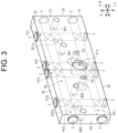
FIG. 3 is a perspective view illustrating a support member; -
FIG. 4 is a partially enlarged view illustrating an air tank, the support member, and electromagnetic on-off valves; -
FIG. 5 is a perspective view illustrating a support member according to a modification; -
FIG. 6 is a partial side view illustrating an air jet loom according to the modification; and -
FIG. 7 is a partial side view illustrating the air jet loom according to the modification. - The following will describe an embodiment of a weft insertion device of an air jet loom with reference to
FIGS. 1 to 4 . - As illustrated in
FIGS. 1 and2 , anair jet loom 100 includes a pair ofside frames 11, arocking shaft 12, asley 13, aprofile reed 16, a main nozzle M, and aweft insertion device 20. - As illustrated in
FIG. 1 , the pair ofside frames 11 is spaced from each other in a width direction W of theair jet loom 100. Although not illustrated in detail, the rockingshaft 12 is mounted on the pair ofside frames 11 so as to extend in the width direction W of theairjet loom 100. Opposite ends of therocking shaft 12 in the extending direction thereof are supported by theside frames 11 so as to reciprocate and be rotatable. - As illustrated in
FIG. 2 , therocking shaft 12 includes anarm 12a that extends above theair jet loom 100. Thearm 12a is formed integrally with the rockingshaft 12. Thesley 13 is supported on an upper end of thearm 12a. Thesley 13 extends in the width direction W of theair jet loom 100. Thesley 13 rotationally moves integrally with the rockingshaft 12. - The
profile reed 16 is supported by thesley 13. A lower end of theprofile reed 16 is fixed to thesley 13. Theprofile reed 16 is formed of a plurality ofdents 16a arranged in a row in the width direction W of theair jet loom 100. It is noted that only one of the plurality ofdents 16a is illustrated inFIG. 2 . - As illustrated in
FIG. 1 , thedents 16a are arranged on thesley 13 at intervals in the width direction W of theair jet loom 100. A lower end of each of thedents 16a is fixed to thesley 13, so that thedents 16a are supported by thesley 13. Theprofile reed 16 has areed passage 16b. Thereed passage 16b extends in the width direction W of theair jet loom 100. That is, thereed passage 16b extends in a direction in which thedents 16a are arranged. Thereed passage 16b is opened at opposite ends of theprofile reed 16 in the direction in which thedents 16a are arranged. - The main nozzle M is connected to a pressure supply source (not illustrated), and a weft yarn Y is ejected from the main nozzle M into the
reed passage 16b. The weft yarn Y ejected into thereed passage 16b travels through thereed passage 16b in the width direction W of theair jet loom 100. That is, theair jet loom 100 inserts the weft yarn Y into thereed passage 16b by the main nozzle M. A direction in which the weft yarn Y ejected from the main nozzle M travels is defined as a weft insertion direction X. The weft insertion direction X coincides with the width direction W of theair jet loom 100. Thus, thereed passage 16b extends in the weft insertion direction X. - The
weft insertion device 20 includes anair tank 10, a plurality of sub-nozzles S, a plurality ofsupport members 21, a plurality of electromagnetic on-offvalves 22, and a plurality offlexible tubes 23. - The
air tank 10 has an elongated shape having a long side direction extending in the width direction W of theair jet loom 100, i.e., the weft insertion direction X. Opposite ends of theair tank 10 in the long side direction thereof are supported by theside frames 11. In other words, theair tank 10 is supported by the pair ofside frames 11 and is mounted over the pair ofside frames 11. Theair tank 10 extends in the width direction W of theair jet loom 100 and functions as a beam of a fixedly provided loom frame. - As illustrated in
FIG. 2 , atank chamber 10b is formed inside theair tank 10. Compressed air is supplied from the pressure supply source (not illustrated) to theair tank 10 and stored in thetank chamber 10b. That is, theair tank 10 stores compressed air. - As illustrated in
FIG. 1 , theair tank 10 has a plurality oftank holes 10a arranged in the long side direction of theair tank 10. That is, the plurality oftank holes 10a is formed in theair tank 10 in the weft insertion direction X. As illustrated inFIG. 4 , a pair of fourth fixing holes H4 is formed in theair tank 10 so that the fourth fixing holes H4 are disposed on opposite sides of each of thetank holes 10a in the weft insertion direction X. - As illustrated in
FIG. 2 , in the air jet loom 100, a side to which theprofile reed 16 moves for beating is defined as a front, and a side to which theprofile reed 16 returns after beating is defined as a rear. It can be said that theprofile reed 16 rotationally moves in a front-rear direction F of the air jet loom 100. - The sub-nozzles S are disposed between the
profile reed 16 and theair tank 10 in the front-rear direction F of the air jet loom 100. The sub-nozzles S are arranged in the long side direction of theair tank 10. In other words, the sub-nozzles S are arranged in the weft insertion direction X. The sub-nozzles S are attached to thesley 13. That is, the sub-nozzles S are supported by thesley 13 so as to be rotationally movable integrally with the rockingshaft 12. - A first end of each of the
flexible tubes 23 is connected to its associated one of the sub-nozzles S. A second end of each of theflexible tubes 23 is connected to its associated one of the electromagnetic on-offvalves 22. - As illustrated in
FIG. 1 , the electromagnetic on-offvalves 22 are attached to theair tank 10 via thesupport members 21. The electromagnetic on-offvalves 22 are arranged in line in the long side direction of theair tank 10. In other words, the electromagnetic on-offvalves 22 are provided in the weft insertion direction X. - The electromagnetic on-off
valves 22 each have oneinlet port 22a through which compressed air flows in, and twooutlet ports 22b. That is, the electromagnetic on-offvalves 22 each have theinlet port 22a through which compressed air flows in. The second end of each of theflexible tube 23 is connected to its associated one of theoutlet ports 22b. Compressed air flowing into the electromagnetic on-offvalves 22 through theinlet ports 22a via thesupport members 21, which will be described later, passes through avalve passage 22c formed inside each of the electromagnetic on-offvalves 22 and is discharged to its associated one of theflexible tubes 23 through its associated one of theoutlet ports 22b. Compressed air is supplied to each of the electromagnetic on-offvalves 22 through its associatedinlet port 22a, and is discharged from its associated two sub-nozzles S via thevalve passage 22c, the twooutlet ports 22b, and the twoflexible tubes 23. - Therefore, compressed air is supplied to the sub-nozzles S from the
air tank 10 via theflexible tubes 23, the electromagnetic on-offvalves 22, and thesupport members 21, which will be described later. Compressed air supplied from theair tank 10 is ejected from the sub-nozzles S. Compressed air is ejected from the sub-nozzles S into thereed passage 16b. - The electromagnetic on-off
valves 22 each are switchable between an energized state in which theinlet port 22a and theoutlet ports 22b are in communication with each other, and a deenergized state in which theinlet port 22a and theoutlet ports 22b are shut off from each other. The electromagnetic on-offvalves 22 each are connected to a control device (not illustrated) and switched between the energized state and the deenergized state in response to a signal from the control device. The control device can control each of the electromagnetic on-offvalves 22 individually. For example, the control device can set one of the plurality of electromagnetic on-offvalves 22 to an energized state and the others of the electromagnetic on-offvalves 22 to the deenergized state. That is, the electromagnetic on-offvalves 22 control supply of compressed air from theair tank 10 to the sub-nozzles S. - As illustrated in
FIG. 4 , the electromagnetic on-offvalves 22 each have a pair of first fixing holes H1. The first fixing holes H1 are opened at one surface of each of the electromagnetic on-offvalves 22 on a side of theair tank 10 and at another surface that is a surface opposite to the one surface. - The
support members 21 each are interposed between the electromagnetic on-offvalves 22 and theair tank 10. Thesupport members 21 each have a plate shape that has a long side extending in the weft insertion direction X, and a thickness extending in the front-rear direction F. Thesupport members 21 each have a plate shape that has a short side extending in an up-down direction U. Thus, thesupport members 21 each have a rectangular plate shape. In the following description, for the sake of description, only onesupport member 21 will be described as an example, though theweft insertion device 20 includes the plurality ofsupport members 21. Additionally, a direction of thesupport member 21 that coincides with the front-rear direction F of the air jet loom 100 is referred to as a thickness direction T. Thesupport member 21 has atank side surface 31 and avalve side surface 32 opposite to thetank side surface 31 in the thickness direction T. That is, thesupport member 21 has a plate shape, and has thetank side surface 31 and thevalve side surface 32 on opposite sides in the thickness direction T. Thesupport member 21 has afirst side surface 33, and asecond side surface 34 that is a surface opposite to thefirst side surface 33 in the weft insertion direction X. Thesupport member 21 is attached to theair tank 10 with the long side direction of thesupport member 21 coinciding with the weft insertion direction X. Thus, the weft insertion direction X of thesupport member 21 may be interpreted as the long side direction of thesupport member 21. Thesupport member 21 is attached to theair tank 10 with the short side direction of thesupport member 21 coinciding with the up-down direction U. Thus, the up-down direction U of thesupport member 21 may be interpreted as the short side direction of thesupport member 21. - In the
support member 21, thefirst side surface 33 is disposed on a side of the main nozzle M in the weft insertion direction X. Thesupport member 21 has alower surface 35 facing downward in the up-down direction U, which is a direction perpendicular to the thickness direction T and the weft insertion direction X, and anupper surface 36 facing upward and opposite to thelower surface 35. - As illustrated in
FIG. 3 , thesupport member 21 has atank connection port 31a formed in thetank side surface 31. That is, thetank side surface 31 has thetank connection port 31a. Thetank connection port 31a is formed in the center of thesupport member 21 in the weft insertion direction X and closer to thelower surface 35 in the up-down direction U. - Further, the
support member 21 has a firstvalve connection port 321a and a secondvalve connection port 322a, which correspond to a plurality of valve connection ports, in thevalve side surface 32. That is, thevalve side surface 32 is a surface different from thetank side surface 31, and has the firstvalve connection port 321a and the secondvalve connection port 322a. The firstvalve connection port 321a is formed at a position closer to thefirst side surface 33 than thetank connection port 31a in the weft insertion direction X. The secondvalve connection port 322a is formed at a position closer to thesecond side surface 34 than thetank connection port 31a in the weft insertion direction X. The firstvalve connection port 321a and the secondvalve connection port 322a are formed at positions spaced from each other in the weft insertion direction X. The firstvalve connection port 321a and the secondvalve connection port 322a are formed closer to theupper surface 36 than thetank connection port 31a in the up-down direction U. - As illustrated in
FIG. 4 , thesupport member 21 is disposed at a position where thetank side surface 31 faces theair tank 10 and thetank connection port 31a is in communication with one of the plurality oftank holes 10a. That is, thesupport member 21 has thetank connection port 31a in communication with one of thetank holes 10a. - A distance from the
tank connection port 31a to the firstvalve connection port 321a in the weft insertion direction X is the same as a distance from thetank connection port 31a to the secondvalve connection port 322a. - The
support member 21 is disposed at a position where thevalve side surface 32 faces the two electromagnetic on-offvalves 22. Further, thesupport member 21 is disposed at a position where theinlet ports 22a of the two electromagnetic on-offvalves 22 are in communication with the firstvalve connection port 321a and the secondvalve connection port 322a, respectively. That is, thesupport member 21 has the firstvalve connection port 321a and the secondvalve connection port 322a in communication with theinlet ports 22a. - As illustrated in
FIG. 3 , aninternal flow passage 40 is formed in an inside of thesupport member 21, and connects thetank connection port 31a with the firstvalve connection port 321a and the secondvalve connection port 322a. Theinternal flow passage 40 has a first horizontal flow passage PX1, a second horizontal flow passage PX2, a first vertical flow passage PZ1, a second vertical flow passage PZ2, a third vertical flow passage PZ3, and a fourth vertical flow passage PZ4. - The first horizontal flow passage PX1 extends in the weft insertion direction X, and is closed by closing members C at the
first side surface 33 and thesecond side surface 34. The second horizontal flow passage PX2 extends in the weft insertion direction X, and is closed by closing members C at thefirst side surface 33 and thesecond side surface 34. The first horizontal flow passage PX1 and the second horizontal flow passage PX2 are arranged in this order from thelower surface 35 to theupper surface 36 in the up-down direction U. - Each of the first to fourth vertical flow passages PZ1 to PZ4 extends in the up-down direction U, and is closed by the closing members C at the
lower surface 35 and theupper surface 36. The first to fourth vertical flow passages PZ1 to PZ4 are arranged in the weft insertion direction X in order of the first vertical flow passage PZ1, the second vertical flow passage PZ2, the third vertical flow passage PZ3, and the fourth vertical flow passage PZ4 from thefirst side surface 33 to thesecond side surface 34. - The second vertical flow passage PZ2 and the third vertical flow passage PZ3 are formed in a central portion of the
support member 21 in the weft insertion direction X. The second vertical flow passage PZ2 and the third vertical flow passage PZ3 are slightly spaced from each other in the weft insertion direction X. The second vertical flow passage PZ2 and the third vertical flow passage PZ3 are disposed at positions overlapping thetank connection port 31a in the thickness direction T of thesupport member 21. - The first vertical flow passage PZ1 is formed at a position spaced from the second vertical flow passage PZ2 on the
first side surface 33 side in the weft insertion direction X. The first vertical flow passage PZ1 is disposed at a position overlapping the firstvalve connection port 321a in the thickness direction T of thesupport member 21. The fourth vertical flow passage PZ4 is formed at a position spaced from the third vertical flow passage PZ3 on thesecond side surface 34 side in the weft insertion direction X. The fourth vertical flow passage PZ4 is disposed at a position overlapping the secondvalve connection port 322a in the thickness direction T of thesupport member 21. A distance between the first vertical flow passage PZ1 and the second vertical flow passage PZ2 in the weft insertion direction X is the same as a distance between the third vertical flow passage PZ3 and the fourth vertical flow passage PZ4 in the weft insertion direction X. - The first horizontal flow passage PX1 and the second horizontal flow passage PX2 are in communication with each other inside the
support member 21 via the first to fourth vertical flow passages PY1 to PY4. In other words, thesupport member 21 has theinternal flow passage 40 formed within a thickness of thesupport member 21. - The second vertical flow passage PZ2 and the third vertical flow passage PZ3 are in communication with the
tank connection port 31a. That is, the second vertical flow passage PZ2 and the third vertical flow passage PZ3 each are opened to thetank side surface 31 through thetank connection port 31a. - The first vertical flow passage PZ1 is in communication with the first
valve connection port 321a. In addition, the fourth vertical flow passage PZ4 is in communication with the secondvalve connection port 322a. That is, the first vertical flow passage PZ1 is opened at thevalve side surface 32 via the firstvalve connection port 321a, and the fourth vertical flow passage PZ4 is opened at thevalve side surface 32 via the secondvalve connection port 322a. - The
tank connection port 31a and the firstvalve connection port 321a are in communication with each other through the second vertical flow passage PZ2, the first horizontal flow passage PX1, the second horizontal flow passage PX2, and the first vertical flow passage PZ1. Thetank connection port 31a and the secondvalve connection port 322a are in communication with each other through the third vertical flow passage PZ3, the first horizontal flow passage PX1, the second horizontal flow passage PX2, and the fourth vertical flow passage PZ4. - The
support member 21 has paired first valve fixing holes BH1 and paired second valve fixing holes BH2 each opened at thetank side surface 31 and thevalve side surface 32. The paired first valve fixing holes BH1 and the paired second valve fixing holes BH2 each correspond to a pair of second fixing holes. The paired first valve fixing holes BH1 and the paired second valve fixing holes BH2 are formed side by side in the weft insertion direction X. - The paired first valve fixing holes BH1 are formed in the
support member 21 closer to thefirst side surface 33 than the central portion in the weft insertion direction X, and the paired second valve fixing holes BH2 is formed in thesupport member 21 closer to thesecond side surface 34 than the central portion in the weft insertion direction X. - As illustrated in
FIG. 4 , the paired first valve fixing holes BH1 are formed at positions at which the firstvalve connection port 321a is disposed between the paired first valve fixing holes BH1 in the weft insertion direction X of thesupport member 21. The paired first valve fixing holes BH1 face the pair of first fixing holes H1 in a state in which the electromagnetic on-offvalves 22 and thesupport member 21 provide communication between theinlet port 22a and the firstvalve connection port 321a. A hole diameter of each of the paired first valve fixing holes BH1 is the same as that of each of the pair of first fixing holes H1 formed in each of the electromagnetic on-offvalves 22. In addition, a pitch between the paired first valve fixing holes BH1 is the same as a pitch between the pair of first fixing holes H1. It is noted that the pitch between the paired first valve fixing holes BH1 corresponds to a distance between the centers of the paired first valve fixing holes BH1 in the weft insertion direction X. In addition, a pitch between the pair of first fixing holes H1 corresponds to a distance between the centers of the first fixing holes H1 in the weft insertion direction X. - The paired second valve fixing holes BH2 are disposed at positions at which the second
valve connection port 322a is disposed between the paired second valve fixing holes BH2 in the weft insertion direction X. The paired second valve fixing holes BH2 face the pair of first fixing holes H1 in a state in which the electromagnetic on-offvalves 22 and thesupport member 21 provide communication between theinlet port 22a and the secondvalve connection port 322a. - Of the electromagnetic on-off
valves 22, one electromagnetic on-offvalve 22 having theinlet port 22a in communication with the paired second valve fixing holes BH2 is different from another electromagnetic on-offvalve 22 having theinlet port 22a in communication with the paired first valve fixing holes BH1. A hole diameter of each of the paired second valve fixing holes BH2 is the same as that of each of the first fixing holes H1 formed in each of the electromagnetic on-offvalves 22. Further, the pitch between the paired second valve fixing holes BH2 is the same as the pitch between the first fixing holes H1. The pitch between the paired second valve fixing holes BH2 is a distance between the centers of the paired second valve fixing holes BH2 in the weft insertion direction X. - As illustrated in
FIGS. 3 and4 , thesupport member 21 has a pair of third fixing holes H3 that are opened at thetank side surface 31 and thevalve side surface 32. The pair of third fixing holes H3 is formed at a central portion of thesupport member 21 in the weft insertion direction X. The third fixing holes H3 are disposed at positions at which thetank connection port 31a is disposed between the third fixing holes H3 in the weft insertion direction X. - The third fixing holes H3 face the pair of fourth fixing holes H4 formed in the
air tank 10 in a state in which the third fixing holes H3 provide communication between thetank hole 10a and thetank connection port 31a. A hole diameter of each of the third fixing holes H3 is the same as that of each of the fourth fixing holes H4. The pitch between the pair of third fixing holes H3 is the same as that between the pair of fourth fixing holes H4. The pitch between the pair of third fixing holes H3 is a distance between the centers of the third fixing holes H3 in the weft insertion direction X. The pitch between the pair of fourth fixing holes H4 is a distance between the centers of the fourth fixing holes H4 in the weft insertion direction X. - In the
support member 21, the hole diameter of each of the paired first valve fixing holes BH1 is the same as that of each of the pair of third fixing holes H3. Further, the pitch between the paired first valve fixing holes BH1 is the same as the pitch between the pair of third fixing holes H3. In thesupport member 21, the hole diameter of each of the paired second valve fixing holes BH2 is the same as that of each of the pair of third fixing holes H3. Further, the pitch between the paired second valve fixing holes BH2 is the same as the pitch between the pair of third fixing holes H3. - Therefore, the hole diameter of each of the first fixing holes H1, the hole diameter of each of the paired first valve fixing holes BH1, the hole diameter of each of the paired second valve fixing holes BH2, the hole diameter of each of the third fixing holes H3, and the hole diameter of each of the fourth fixing holes H4 are the same. The pitch between the pair of first fixing holes H1, the pitch between the paired first valve fixing holes BH1, the pitch between the paired second valve fixing holes BH2, the pitch between the pair of third fixing holes H3, and the pitch between the pair of fourth fixing holes H4 are the same.
- As illustrated in
FIGS. 1 and4 , two electromagnetic on-offvalves 22 are attached to thesupport member 21. Each of the two electromagnetic on-offvalves 22 is fixed to thesupport member 21 by a pair of first fixing pins F1, which corresponds to valve fixing members. A first electromagnetic on-offvalve 221, which is one of the two electromagnetic on-offvalves 22, is provided at a position where theinlet port 22a is in communication with the firstvalve connection port 321a, and a second electromagnetic on-offvalve 222, which is the other of the two electromagnetic on-offvalves 22, is provided at a position where theinlet port 22a is in communication with the secondvalve connection port 322a. The first electromagnetic on-offvalve 221 is fixed to thesupport member 21 with the first fixing pins F1 inserted into the pair of first fixing holes H1 and the paired first valve fixing holes BH1. The second electromagnetic on-offvalve 222 is fixed to thesupport member 21 with the first fixing pins F1 inserted into the pair of first fixing holes H1 and the paired second valve fixing holes BH2. That is, the electromagnetic on-offvalves 22 may be attached to thesupport member 21 with the first fixing pins F1 inserted through the pair of first fixing holes H1 and inserted into the paired first valve fixing holes BH1 and the paired second valve fixing holes BH2. It is noted that the first fixing pins F1 may be press-fitted into the paired first valve fixing holes BH1 and the paired second valve fixing holes BH2, or male threads of the first fixing pins F1 may be screwed into female threads of the paired first valve fixing holes BH1 and the paired second valve fixing holes BH2. - The
support member 21 to which the two electromagnetic on-offvalves 22 are attached is fixed to theair tank 10 with a pair of second fixing pins F2, which corresponds to support fixing members. The pair of second fixing pins F2 are inserted through the pair of third fixing holes H3 and fixed to the pair of fourth fixing holes H4. That is, thesupport member 21 is attachable to theair tank 10 with the pair of second fixing pins F2 inserted through the third fixing holes H3 and inserted into the pair of fourth fixing holes H4. That is, thesupport member 21 is attached to theair tank 10 and supports the electromagnetic on-offvalves 22. The second fixing pins F2 may be press-fitted into the fourth fixing holes H4, or male threads of the second fixing pins F2 may be screwed into female threads of the fourth fixing holes H4. - The electromagnetic on-off
valves 22 may be attached to theair tank 10 without using thesupport member 21. In this case, each of the electromagnetic on-offvalves 22 is provided at a position where theinlet port 22a is in communication with thetank hole 10a, and the first fixing pins F1 inserted through the first fixing holes H1 are inserted into the fourth fixing holes H4. As a result, one electromagnetic on-offvalve 22 can be connected to onetank hole 10a. - As illustrated in
FIGS. 1 and2 , during the operation of the airjet loom 100, the weft yarn Y is ejected from the main nozzle M and travels through thereed passage 16b in the weft insertion direction X. When the weft yarn Y travels through thereed passage 16b, compressed air supplied from theair tank 10 is discharged from the plurality of sub-nozzles S of theweft insertion device 20. Discharge of air from the sub-nozzles S is performed as in a relay, i.e., relay air jet, from the main nozzle M side in the weft insertion direction X. The relay air jet propels the weft yarn Y ejected to into an opening of warp yarns TT. The relay air jet is performed by switching each of the electromagnetic on-offvalves 22 between the energized state and the deenergized state by the control device (not illustrated). Compressed air is supplied to the sub-nozzles S via thesupport member 21, the electromagnetic on-offvalves 22, and theflexible tubes 23. - The weft yarn Y inserted by the
weft insertion device 20 is beaten against a cloth fell N1 by theprofile reed 16 which is rotationally moved by the rockingshaft 12. As a result of the beating, the weft yarn Y and the warp yarns TT form a woven fabric N. - The following will describe operation of the present embodiment.
- In the
weft insertion device 20 provided in the air jet loom 100, compressed air is discharged from the sub-nozzles S to the weft yarn Y inserted in thereed passage 16b. The sub-nozzles S are connected to their associated electromagnetic on-offvalves 22. The electromagnetic on-offvalves 22 control supply of compressed air from theair tank 10 to the sub-nozzles S. Compressed air is supplied to the electromagnetic on-offvalves 22 from theair tank 10 via theinternal flow passage 40 of thesupport member 21. Compressed air stored in theair tank 10 flows into theinternal flow passages 40 of thesupport member 21 via thetank holes 10a and thetank connection ports 31a. Compressed air flowing through theinternal flow passage 40 of thesupport member 21 is supplied to the electromagnetic on-offvalves 22 via the firstvalve connection ports 321a and the secondvalve connection ports 322a. That is, theair tank 10 to which thesupport member 21 is attached supplies compressed air to the two electromagnetic on-offvalves 22 through onetank hole 10a. - The following will describe effects of the present embodiment.
- (1) In the
weft insertion device 20, thesupport member 21 allows the two electromagnetic on-offvalves 22 to be connected to onetank hole 10a. In other words, thesupport member 21 can increase the number of electromagnetic on-offvalves 22 attached to theair tank 10. As a result, theweft insertion device 20 can increase the number of the electromagnetic on-offvalves 22 attached to theair tank 10 by attaching thesupport member 21 without replacing theair tank 10.
Furthermore, by using thesupport member 21, theweft insertion device 20 can increase the number of the electromagnetic on-offvalves 22 in the weft insertion direction X without changing the number of the sub-nozzles S. In this case, the number of the sub-nozzles S connected to one electromagnetic on-offvalve 22 decreases. In other words, theweft insertion device 20 can shorten a distance between each of the electromagnetic on-offvalves 22 and its associated sub-nozzles S connected thereto in the weft insertion direction X, as compared with a case where thesupport member 21 is not provided. As a result, theweft insertion device 20 can reduce the pressure loss of compressed air between the electromagnetic on-offvalves 22 and the sub-nozzles S. - (2) The
support member 21 has a plate-shape, and theinternal flow passage 40 is formed within the thickness of thesupport member 21. For example, as compared with a case where theinternal flow passage 40 has a bent shape in accordance with the bending of thesupport member 21 such as an L shape as viewed in the weft insertion direction X, theinternal flow passage 40 can be manufactured more easily. In other words, the above structure allows thesupport member 21 to be manufactured easily.
In addition, thesupport member 21 is directly attached to theair tank 10 and supports the electromagnetic on-offvalves 22. In thesupport member 21, the flow passage is branched inside thesupport member 21 in order to connect onetank hole 10a and the electromagnetic on-offvalves 22 via theinternal flow passage 40.
As a configuration for connecting the plurality of electromagnetic on-offvalves 22 to onetank hole 10a, for example, a configuration in which a branching member that branches compressed air for the electromagnetic on-offvalves 22 is supported by a support member and the branching member is connected to theair tank 10 by a tubular member or the like can be considered. This configuration requires the branching member and the support member separately. Therefore, the configuration of the present embodiment in which thesupport member 21 is attached to theair tank 10 reduces the number of parts and manhour required for attaching the parts, as compared with the above configuration. Furthermore, since there is no need to attach the tubular member or the like, thesupport member 21 and the electromagnetic on-offvalves 22 may be attached to theair tank 10 easily, as compared with the case where the branching member and theair tank 10 are connected by the tubular member or the like. - (3) In the
support member 21, thetank connection port 31a, the firstvalve connection port 321a, and the secondvalve connection port 322a are formed in thetank side surface 31 and thevalve side surface 32 that are aligned in the thickness direction T. This configuration allows the thickness of thesupport member 21 to be changed while providing thetank connection port 31a, the firstvalve connection port 321a, and the secondvalve connection port 322a. As a result, enlargement of theweft insertion device 20 of the air jet loom 100 may be suppressed by changing the thickness of thesupport member 21 in accordance with a size of a space between theair tank 10 and thearm 12a where thesupport member 21 and the electromagnetic on-offvalves 22 are disposed. - (4) In the
support member 21, the firstvalve connection port 321a and the secondvalve connection port 322a are formed closer to theupper surface 36 than thetank connection port 31a in the up-down direction U of thesupport member 21. In other words, the electromagnetic on-offvalves 22 attached to theair tank 10 by thesupport member 21 are closer to the sub-nozzles S as compared with a case where the electromagnetic on-offvalves 22 are attached to theair tank 10 without thesupport member 21. As a result, in theweft insertion device 20, the distance between the electromagnetic on-offvalves 22 and the sub-nozzles S can be shortened, so that the pressure loss of compressed air occurring between the electromagnetic on-offvalves 22 and the sub-nozzles S can be reduced. - (5) To the
air tank 10, the electromagnetic on-offvalves 22 can be directly attached by inserting the pair of first fixing pins F1 through the pair of first fixing holes H1 and into the pair of fourth fixing holes H4. Further, to theair tank 10, thesupport member 21 can be attached by inserting the second fixing pin F2 through the pair of third fixing holes H3 and into the pair of fourth fixing holes H4. In other words, the pair of fourth fixing holes H4 for attaching thesupport member 21 to theair tank 10 can also be used as fixing holes for directly attaching the electromagnetic on-offvalves 22 to theair tank 10. Therefore, there is no need to provide a new hole in theair tank 10. As a result, theweft insertion device 20 of the air jet loom 100 allows thesupport member 21 to be attached without processing theair tank 10 to which the electromagnetic on-offvalves 22 had been attached. - (6) In the
support member 21, the distance between the first vertical flow passage PZ1 and the second vertical flow passage PZ2 in the weft insertion direction X is the same as the distance between the third vertical flow passage PZ3 and the fourth vertical flow passage PZ4 in the weft insertion direction X. Therefore, the distance from thetank connection port 31a to the firstvalve connection port 321a in the weft insertion direction X is the same as the distance from thetank connection port 31a to the secondvalve connection port 322a in the weft insertion direction X. That is, the distances for compressed air to be supplied to the two electromagnetic on-offvalves 22 supported by thesupport member 21 to pass though theinternal flow passage 40 are equal. In other words, pressure losses of compressed air supplied to the two electromagnetic on-offvalves 22 are equal. Therefore, theweft insertion device 20 allows the pressure of the compressed air supplied from the electromagnetic on-offvalves 22 to be uniform while increasing the number of the electromagnetic on-offvalves 22 attached to theair tank 10. As a result, theweft insertion device 20 can insert the weft yarn Y with high accuracy while increasing the number of the electromagnetic on-offvalves 22. - The above embodiment may be modified as follows. The above embodiment and the following modification may be combined with each other as long as they do not technically contradict each other.
- The
support member 21 may have a valve connection port in communication with theinlet port 22a of each of the electromagnetic on-offvalves 22, in addition to the firstvalve connection port 321a and the secondvalve connection port 322a. In this case, thesupport member 21 has paired valve fixing holes different from the paired first valve fixing holes BH1 and the paired second valve fixing holes BH2. - The hole diameter of each of the third fixing holes H3 does not have to be the same as that of each of the fourth fixing holes H4, and the pitch between the third fixing holes H3 does not have to be the same as that between the fourth fixing holes H4. In this case, in order to attach the
support member 21, holes different from the pair of fourth fixing holes H4 are provided in theair tank 10. - Any one of the dimensions of the
support member 21 in the thickness direction T, in the weft insertion direction X, and in the up-down direction U may be changed as appropriate. In other words, thesupport member 21 does not have to have a plate shape. - As illustrated in
FIG. 5 , thesupport member 21 may be configured such that thesupport member 21 can be disassembled. For example, thesupport member 21 includes a first forming member A1 and a second forming member A2 aligned in the thickness direction T, a sealing member A3 that provides sealing between the first forming member A1 and the second forming member A2, and a plurality of connecting pins A4 for attaching the second forming member A2 to the first forming member A1. Thesupport member 21 is formed by arranging the first forming member A1 and the second forming member A2 facing each other in the thickness direction T. - The
support member 21 has atank side surface 31 on a surface of the first forming member A1 that is different from a surface facing the second forming member A2. That is, the first forming member A1 has thetank connection port 31a. Thetank connection port 31a is opened at opposite surfaces of the first forming member A1 in the thickness direction thereof. - The
support member 21 has avalve side surface 32 on a surface of the second forming member A2 that is different from a surface facing the first forming member A1. That is, the second forming member A2 has the firstvalve connection port 321a and the secondvalve connection port 322a. Each of the firstvalve connection port 321a and the secondvalve connection port 322a is opened at opposite surfaces of the second forming member A2 in the thickness direction. - A flow passage forming space A5 is formed in the
support member 21. The flow passage forming space A5 has a first forming space A51 and a second forming space A52. The first forming space A51 is defined by a first defining portion A511 of the first forming member A1. That is, the first forming space A51 is formed in the first forming member A1. The first forming space A51 is recessed from a surface of the first forming member A1 facing the second forming member A2. The first forming space A51 is opened at the surface where the first defining portion A511 is formed, and in communication with thetank connection port 31a. That is, the first forming member A1 has thetank connection port 31a and the first forming space A51 in communication with thetank connection port 31a. - The second forming space A52 is defined by a second defining portion A521 of the second forming member A2. That is, the second forming space A52 is formed in the second forming member A2. The second forming space A52 is recessed from a surface of the second forming member A2 facing the first forming member A1. The second forming space A52 is opened at the surface where the second defining portion A521 is formed, and in communication with the first
valve connection port 321a and the secondvalve connection port 322a. In other words, the second forming member A2 has the firstvalve connection port 321a and the secondvalve connection port 322a, as well as the second forming space A52 in communication with the firstvalve connection port 321a and the secondvalve connection port 322a. - The first forming member A1 and the second forming member A2 are connected by a plurality of connecting pins A4 so that the first forming space A51 and the second forming space A52 form the flow passage forming space A5. The
tank connection port 31a is in communication with the firstvalve connection port 321a and the secondvalve connection port 322a via the flow passage forming space A5. In other words, theinternal flow passage 40 is formed by the flow passage forming space A5. - It is noted that the second forming member A2 does not have to include the second defining portion A521 and the second forming space A52. In this case, the second forming member A2 closes the first forming space A51. The flow passage forming space A5 is formed in the first forming member A1. Therefore, the
internal flow passage 40 is defined by closing the flow passage forming space A5 with the second forming member A2. - In addition, the first forming member A1 does not have to include the first defining portion A511 and the first forming space A51. In this case, the first forming member A1 closes the second forming space A52. The flow passage forming space A5 is formed in the second forming member A2. Therefore, the
internal flow passage 40 is defined by closing the flow passage forming space A5 with the first forming member A1. In other words, the flow passage forming space A5 is formed in at least one of the first forming member A1 and the second forming member A2, and theinternal flow passage 40 is defined with the flow passage forming space A5 closed by at least the other of the first forming member A1 and the second forming member A2. - In the above configuration, the
internal flow passage 40 is formed by the first forming member A1 and the second forming member A2. This configuration allows the internal flow passage to be formed more easily, as compared with a case where the internal flow passage is formed inside thesupport member 21 formed from a single member. Furthermore, unlike the case where thesupport member 21 is formed from a single member, there is no need to form holes in thesupport member 21 as flow passages. Therefore, theinternal flow passage 40 having a rectangular cross-sectional shape may be formed, for example, by forming the flow passage forming space A5 as a recessed portion. As a result, a path and a cross-sectional shape of theinternal flow passage 40 can be formed more easily, as compared with a case where thesupport member 21 is formed from a single member. Furthermore, the above configuration allows an inside of thesupport member 21 to be hollow that is opened at thetank connection port 31a, the firstvalve connection port 321a, and the secondvalve connection port 322a. In this case, the cross section of theinternal flow passage 40 may be made larger, as compared with the case where thesupport member 21 is formed from a single member. As a result, the pressure loss of the compressed air in theinternal flow passage 40 can be reduced. - The
support member 21 does not have to include only thetank side surface 31, thevalve side surface 32, thefirst side surface 33, thesecond side surface 34, thelower surface 35, and theupper surface 36. For example, as illustrated inFIG. 6 , thesupport member 21 may have an inclined surface D between thevalve side surface 32 and theupper surface 36. - The inclined surface D is inclined with respect to the
valve side surface 32 and theupper surface 36 . The inclined surface D faces a direction in which thereed passage 16b is located as viewed from thesupport member 21 in the up-down direction U of the air jet loom 100. The firstvalve connection port 321a and the secondvalve connection port 322a are each formed in the inclined surface D. That is, thesupport member 21 has the inclined surface D facing the direction in which thereed passage 16b is located, and the electromagnetic on-offvalves 22 are supported on the inclined surface D. The electromagnetic on-offvalves 22 are disposed on the inclined surface D such that theinlet port 22a is in communication with and the firstvalve connection port 321a and the secondvalve connection port 322a. Theinternal flow passage 40 is bent inside thesupport member 21. - The inclined surface D faces the
reed passage 16b and thus faces the sub-nozzles S. In other words, by providing thesupport member 21 with the inclined surface D, the distance between the electromagnetic on-offvalves 22 and the sub-nozzles S may be reduced and the electromagnetic on-offvalves 22 may be oriented in a direction in which the sub-nozzles S are located. As a result, the distance for compressed air flowing between the electromagnetic on-offvalves 22 and the sub-nozzles S may be shortened, and thus the pressure loss of compressed air occurring before it reaches the sub-nozzles S may be reduced. - The
support member 21 does not need to have thetank side surface 31 and thevalve side surface 32 on opposite sides in the thickness direction T. For example, as illustrated inFIG. 7 , thetank side surface 31 and thevalve side surface 32 may face toward theair tank 10. In this case, thesupport member 21 includes a main body portion E1 and a connection portion E2. - The main body portion E1 has a plate shape to which the electromagnetic on-off
valves 22 are attached. The main body portion E1 has a long side extending in the weft insertion direction X and a short side extending in the up-down direction U. A thickness of the main body portion E1 extends in the front-rear direction F. - The connection portion E2 has a plate shape extending from the main body portion E1 toward the
air tank 10. A thickness of the connection portion E2 extends in the up-down direction U. - The
support member 21 has thetank side surface 31, as a surface facing theair tank 10, of surfaces of the connection portion E2. That is, thetank connection port 31a is formed in the connection portion E2. Thesupport member 21 has thevalve side surface 32, as a surface facing theair tank 10, of surfaces of the main body portion E1. That is, a plurality of valve connection ports (not illustrated) is formed in the main body portion E1. - The
internal flow passage 40 is formed in each of the main body portion E1 and the connection portion E2. A main body portion flow passage E3 is formed in the main body portion E1, and a connection portion flow passage E4 is formed in the connection portion E2. The main body portion E1 and the connection portion E2 are connected on thevalve side surface 32 so as to be in communication with the main body portion flow passage E3 and the connection portion flow passage E4. - According to the above configuration, a distance from the electromagnetic on-off
valves 22 attached to thesupport member 21 to the sub-nozzles S is shortened, as compared with the case in which the electromagnetic on-offvalves 22 are attached directly to theair tank 10. In addition, it is possible to reduce the number of times that theflexible tubes 23 each are bent when the electromagnetic on-offvalves 22 and the sub-nozzles S that are located at different positions in the up-down direction U of the air jet loom 100 are connected. As a result, in the above configuration, the pressure loss inside theflexible tubes 23 in compressed air flowing from the electromagnetic on-offvalves 22 to the sub-nozzles S can be reduced.
Claims (5)
- A weft insertion device (20) of an air jet loom (100) in which a weft yarn (Y) is inserted into a reed passage (16b) by a main nozzle (M), the weft insertion device (20) comprising:a plurality of sub-nozzles (S) arranged in a weft insertion direction (X) in which the weft yarn (Y) is inserted, the sub-nozzles (S) being configured to discharge compressed air to the weft yarn (Y) inserted into the reed passage (16b);an air tank (10) in which the compressed air to be discharged from the sub-nozzles (S) is stored, the air tank (10) having a plurality of tank holes (10a) arranged in the weft insertion direction (X);a plurality of electromagnetic on-off valves (22) arranged in the weft insertion direction (X), the electromagnetic on-off valves (22) each having an inlet port (22a) through which the compressed air flows in, and configured to control supply of the compressed air from the air tank (10) to the sub-nozzles (S); anda support member (21) attached to the air tank (10), and supporting the electromagnetic on-off valves (22), characterized in thatthe support member (21) has a tank connection port (31a) in communication with one of the tank holes (10a), and a plurality of valve connection ports (321a, 322a) in communication with the inlet port (22a), andan internal flow passage (40) is formed in an inside of the support member (21), and connects the tank connection port (31a) with the valve connection ports (321a, 322a).
- The weft insertion device (20) of the air jet loom (100) according to claim 1, characterized in thatthe support member (21) hasa tank side surface (31) that has the tank connection port (31a), anda valve side surface (32) that is a surface different from the tank side surface (31) and has the plurality of valve connection ports (321a, 322a), andthe support member (21) has a plate shape, has the tank side surface (31) and the valve side surface (32) on opposite sides of the support member (21) in a thickness direction of the support member (21), and has the internal flow passage (40) formed within a thickness of the support member (21).
- The weft insertion device (20) of the air jet loom (100) according to claim 1 or 2, characterized in thatthe electromagnetic on-off valves (22) each have a pair of first fixing holes (H1),the support member (21) has a pair of second fixing holes (BH1, BH2) and a pair of third fixing holes (H3) different from the pair of second fixing holes (BH1, BH2),the air tank (10) has a pair of fourth fixing holes (H4),the electromagnetic on-off valves (22) each are attachable to the support member (21) with valve fixing members (F1) inserted through the pair of first fixing holes (H1) and inserted into the pair of second fixing holes (BH1, BH2),the support member (21) is attachable to the air tank (10) with support fixing members (F2) inserted though the pair of third fixing holes (H3) and inserted into the pair of fourth fixing holes (H4), anda hole diameter of each of the pair of first fixing holes (H1), a hole diameter of each of the pair of second fixing holes (BH1, BH2), a hole diameter of each of the pair of third fixing holes (H3), and a hole diameter of each of the pair of fourth fixing holes (H4) are the same, and a pitch between the pair of first fixing holes (H1), a pitch between the pair of second fixing holes (BH1, BH2), and a pitch between the pair of third fixing holes (H3), and a pitch between the pair of fourth fixing holes (H4) are the same.
- The weft insertion device (20) of the air jet loom (100) according to claim 2, characterized in thatthe support member (21) includesa first forming member (A1) having the tank connection port (31a), anda second forming member (A2) having the plurality of valve connection ports (321a, 322a),the support member (21) is formed by arranging the first forming member (A1) and the second forming member (A2) facing each other in the thickness direction,a flow passage forming space (A5) is formed in at least one of the first forming member (A1) and the second forming member (A2), andthe internal flow passage (40) is defined with the flow passage forming space (A5) closed by at least the other of the first forming member (A1) and the second forming member (A2).
- The weft insertion device (20) of the air jet loom (100) according to claim 1 or 2, characterized in that
the support member (21) has an inclined surface facing a direction in which the reed passage (16b) is disposed, the electromagnetic on-off valves (22) are supported on the inclined surface, and the valve connection ports (321a, 322a) are opened at the inclined surface.
Applications Claiming Priority (1)
| Application Number | Priority Date | Filing Date | Title |
|---|---|---|---|
| JP2023201712A JP2025087210A (en) | 2023-11-29 | 2023-11-29 | Air jet weaving machine weft insertion device |
Publications (1)
| Publication Number | Publication Date |
|---|---|
| EP4563735A1 true EP4563735A1 (en) | 2025-06-04 |
Family
ID=93432100
Family Applications (1)
| Application Number | Title | Priority Date | Filing Date |
|---|---|---|---|
| EP24211090.6A Withdrawn EP4563735A1 (en) | 2023-11-29 | 2024-11-06 | Air jet loom with weft insertion device |
Country Status (3)
| Country | Link |
|---|---|
| EP (1) | EP4563735A1 (en) |
| JP (1) | JP2025087210A (en) |
| CN (1) | CN120061042A (en) |
Citations (3)
| Publication number | Priority date | Publication date | Assignee | Title |
|---|---|---|---|---|
| EP1086265B1 (en) * | 1998-06-10 | 2002-06-26 | Picanol N.V. | Air feed block for a mechanical loom |
| JP2003239160A (en) | 2002-02-08 | 2003-08-27 | Toyota Industries Corp | Weft inserting apparatus in jet loom |
| EP4163428A1 (en) * | 2021-10-08 | 2023-04-12 | Tsudakoma Kogyo Kabushiki Kaisha | Weft insertion device for air jet loom |
-
2023
- 2023-11-29 JP JP2023201712A patent/JP2025087210A/en active Pending
-
2024
- 2024-11-06 EP EP24211090.6A patent/EP4563735A1/en not_active Withdrawn
- 2024-11-11 CN CN202411598327.3A patent/CN120061042A/en not_active Withdrawn
Patent Citations (3)
| Publication number | Priority date | Publication date | Assignee | Title |
|---|---|---|---|---|
| EP1086265B1 (en) * | 1998-06-10 | 2002-06-26 | Picanol N.V. | Air feed block for a mechanical loom |
| JP2003239160A (en) | 2002-02-08 | 2003-08-27 | Toyota Industries Corp | Weft inserting apparatus in jet loom |
| EP4163428A1 (en) * | 2021-10-08 | 2023-04-12 | Tsudakoma Kogyo Kabushiki Kaisha | Weft insertion device for air jet loom |
Also Published As
| Publication number | Publication date |
|---|---|
| CN120061042A (en) | 2025-05-30 |
| JP2025087210A (en) | 2025-06-10 |
Similar Documents
| Publication | Publication Date | Title |
|---|---|---|
| JP2016172937A (en) | Weft insertion control method in air-jet machine and weft insertion device in air-jet machine | |
| CN101074513B (en) | Picking device for air weaving loom | |
| EP2476788A2 (en) | Weaving method for air jet loom | |
| EP3168346B1 (en) | Air jet loom | |
| EP2610378B1 (en) | Auxiliary nozzle of air jet loom | |
| JP2025087210A (en) | Air jet weaving machine weft insertion device | |
| EP4163428B1 (en) | Weft insertion device for air jet loom | |
| EP3936649B1 (en) | Weft yarn tensioning device | |
| US4244402A (en) | Device for inserting a weft yarn in jet operated weaving machines | |
| EP4575056A1 (en) | Air jet loom | |
| CN101023208B (en) | Jet-weaving machine, particularly an air jet-weaving machine, with a clamping device in the mixing tube | |
| EP2808431B1 (en) | Air jet loom part with weft yarn tension applying apparatus, air jet loom and method of using the air jet loom part | |
| EP3981899B1 (en) | Weft insertion device of air jet loom | |
| EP3964613B1 (en) | Weft insertion device of air jet loom | |
| EP4467696B1 (en) | Air jet loom with weft yarn tensioning device | |
| CN209816399U (en) | Weft insertion system for air jet loom with sley | |
| RU2839502C1 (en) | Receiver for pneumatic loom | |
| JP7429095B2 (en) | air jet loom | |
| CN219099462U (en) | Weft insertion device for shuttleless loom | |
| JP2003221758A (en) | Structural material in weaving machine | |
| JP3405950B2 (en) | Weft guide device for air jet loom | |
| JP3853880B2 (en) | Weft tension applying device in jet loom | |
| CS233626B1 (en) | Weaving loom | |
| CS250167B1 (en) | Apparatus for fabricating an air weaving machine | |
| JPH0262616B2 (en) |
Legal Events
| Date | Code | Title | Description |
|---|---|---|---|
| PUAI | Public reference made under article 153(3) epc to a published international application that has entered the european phase |
Free format text: ORIGINAL CODE: 0009012 |
|
| STAA | Information on the status of an ep patent application or granted ep patent |
Free format text: STATUS: REQUEST FOR EXAMINATION WAS MADE |
|
| 17P | Request for examination filed |
Effective date: 20241106 |
|
| AK | Designated contracting states |
Kind code of ref document: A1 Designated state(s): AL AT BE BG CH CY CZ DE DK EE ES FI FR GB GR HR HU IE IS IT LI LT LU LV MC ME MK MT NL NO PL PT RO RS SE SI SK SM TR |
|
| STAA | Information on the status of an ep patent application or granted ep patent |
Free format text: STATUS: THE APPLICATION HAS BEEN WITHDRAWN |
|
| 18W | Application withdrawn |
Effective date: 20260122 |