EP4563481A1 - Packaging machine configured to produce sealed packages containing a pourable product, removable printing kit for such packaging machine and method for producing packages containing a pourable product - Google Patents
Packaging machine configured to produce sealed packages containing a pourable product, removable printing kit for such packaging machine and method for producing packages containing a pourable product Download PDFInfo
- Publication number
- EP4563481A1 EP4563481A1 EP24214060.6A EP24214060A EP4563481A1 EP 4563481 A1 EP4563481 A1 EP 4563481A1 EP 24214060 A EP24214060 A EP 24214060A EP 4563481 A1 EP4563481 A1 EP 4563481A1
- Authority
- EP
- European Patent Office
- Prior art keywords
- web
- packaging machine
- tube
- printing
- printer device
- Prior art date
- Legal status (The legal status is an assumption and is not a legal conclusion. Google has not performed a legal analysis and makes no representation as to the accuracy of the status listed.)
- Pending
Links
Images



Classifications
-
- B—PERFORMING OPERATIONS; TRANSPORTING
- B65—CONVEYING; PACKING; STORING; HANDLING THIN OR FILAMENTARY MATERIAL
- B65B—MACHINES, APPARATUS OR DEVICES FOR, OR METHODS OF, PACKAGING ARTICLES OR MATERIALS; UNPACKING
- B65B61/00—Auxiliary devices, not otherwise provided for, for operating on sheets, blanks, webs, binding material, containers or packages
- B65B61/02—Auxiliary devices, not otherwise provided for, for operating on sheets, blanks, webs, binding material, containers or packages for perforating, scoring, slitting, or applying code or date marks on material prior to packaging
- B65B61/025—Auxiliary devices, not otherwise provided for, for operating on sheets, blanks, webs, binding material, containers or packages for perforating, scoring, slitting, or applying code or date marks on material prior to packaging for applying, e.g. printing, code or date marks on material prior to packaging
-
- B—PERFORMING OPERATIONS; TRANSPORTING
- B65—CONVEYING; PACKING; STORING; HANDLING THIN OR FILAMENTARY MATERIAL
- B65B—MACHINES, APPARATUS OR DEVICES FOR, OR METHODS OF, PACKAGING ARTICLES OR MATERIALS; UNPACKING
- B65B57/00—Automatic control, checking, warning, or safety devices
- B65B57/02—Automatic control, checking, warning, or safety devices responsive to absence, presence, abnormal feed, or misplacement of binding or wrapping material, containers, or packages
-
- B—PERFORMING OPERATIONS; TRANSPORTING
- B65—CONVEYING; PACKING; STORING; HANDLING THIN OR FILAMENTARY MATERIAL
- B65B—MACHINES, APPARATUS OR DEVICES FOR, OR METHODS OF, PACKAGING ARTICLES OR MATERIALS; UNPACKING
- B65B9/00—Enclosing successive articles, or quantities of material, e.g. liquids or semiliquids, in flat, folded, or tubular webs of flexible sheet material; Subdividing filled flexible tubes to form packages
- B65B9/10—Enclosing successive articles, or quantities of material, in preformed tubular webs, or in webs formed into tubes around filling nozzles, e.g. extruded tubular webs
- B65B9/20—Enclosing successive articles, or quantities of material, in preformed tubular webs, or in webs formed into tubes around filling nozzles, e.g. extruded tubular webs the webs being formed into tubes in situ around the filling nozzles
Definitions
- the present invention relates to a packaging machine configured to produce sealed packages containing a pourable product, preferably a pourable food product.
- the present invention also relates to a removable printing kit for such a packaging machine, and in particular implementable in such a packaging machine in a removable manner.
- the present invention further relates to a method for producing packages containing a pourable product, preferably a pourable food product.
- pourable food products such as fruit juice, UHT (ultra-high temperature-treated) milk, wine, tomato sauce, etc.
- UHT ultra-high temperature-treated milk
- wine tomato sauce
- etc. are sold in packages made of sterilized packaging material.
- a typical example is the parallelepiped-shaped package for pourable food products known as Tetra Brik Aseptic (registered trademark), which is made by folding and sealing a laminated web of packaging material.
- the packaging material has a multilayer structure comprising a base layer, e.g. made of paper, covered on both sides with layers of heat-seal plastic material, e.g. polyethylene.
- the packaging material also comprises a layer of oxygen-barrier material, e.g. an aluminum foil, which is superimposed on a layer of heat-seal plastic material, and is in turn covered with another layer of heat-seal plastic material forming the inner face of the package eventually contacting the food product.
- a layer of oxygen-barrier material e.g. an aluminum foil
- Packages of this sort are normally produced on fully automatic packaging lines, which comprise packaging machines configured to form and fill the packages starting from a multilayer packaging material.
- a continuous tube is formed starting from a web of packaging material initially wound in a reel and fed through a plurality of unwinding rollers.
- the web of packaging material is sterilized by a sterilization unit, e.g. by applying a chemical sterilizing agent, such as hydrogen peroxide solution, which, once sterilization is completed, is removed from the surfaces of the packaging material, e.g. evaporated by heating.
- a chemical sterilizing agent such as hydrogen peroxide solution
- the tube is fed continuously along a first direction, normally a straight vertical direction, is filled with the sterilized food product from above and is formed, sealed and subsequently cut along equally spaced transversal cross-sections extending along a second direction, normally a direction orthogonal to the first direction.
- the known packaging machines comprise a forming and sealing unit configured to form the tube, so as to imprint an external shape to it corresponding to the desired shape of the package, and to seal the tube at equally spaced cross-sections orthogonal to the tube advancement direction.
- a packaging machine of the above type comprises a pair of alternately movable forming and sealing jaws which are controllable with a reciprocating movement in the first direction and in a third direction orthogonal to the first direction and second direction to interact with the tube at successive portions thereof.
- pillow packs are obtained thereby, which have a longitudinal sealing band, a top transversal sealing band and a bottom transversal sealing band.
- the pillow packs are then cut at the cross-sections to be separated from one another and directed to a folding unit of the packaging machine for the final folding thereof.
- the known packaging machines comprise a discard device operatively arranged between the forming and sealing unit and the folding unit and configured to discard the faulty packs.
- the packaging machines of the aforementioned type further comprise a printing unit for printing such information on the finished packages.
- a typical packaging machine comprises at least one printing unit arranged in a position operatively downstream of the folding unit and configured to print the data (usually in the form of an alphanumeric code or bar code) on the filled, formed, sealed and folded packages, thereby defining a printing process.
- the need is felt for improving the synchronization between the packaging material and the printing unit during the aforementioned printing process.
- number 1 indicates as a whole a non-limiting example of a packaging machine configured to produce sealed packages 2 containing a pourable product, preferably a pourable food product such as pasteurized or UHT milk, water, fruit juice, wine, peas, beans, etc.
- a pourable product such as pasteurized or UHT milk, water, fruit juice, wine, peas, beans, etc.
- packaging machine 1 is configured to form, seal and fold packages 2 starting from a web 4 of packaging material, which is initially wound in a reel 4a, and then folded into a tube 3 of packaging material, as explained below.
- packaging machine 1 is part of a packaging line (known per se and not shown) configured for producing, grouping and boxing a plurality of packages in a known manner.
- a packaging line known per se and not shown
- packaging machine 1 comprises:
- Tube folding device 5 and sealing element 40 define together a tube forming unit.
- forming and sealing unit 6 has an axis X along which tube 3 is fed, in use.
- Axis X is parallel to a straight direction, which preferably is a straight vertical direction.
- tube 3 is fed along axis X, downwards, and while being filled from above is formed and sealed by forming and sealing unit 6.
- tube 3 is drawn (downwards) along axis X by forming and sealing unit 6 in a known manner.
- packaging machine 1 is configured to form and seal a plurality of pillow packs 2a containing the pourable product starting from web 4 and tube 3 and then to fold the pillow packs 2a for obtaining the aforementioned formed, sealed and folded packages 2 containing the pourable product.
- pillow packs 2a have a main body 41, with a longitudinal sealing band 42 longitudinally extending along main body 41 and two opposite transversal sealing bands 43, one at each longitudinal end portion of the pack 2a.
- packaging machine 1 also comprises a discarding or sorting device (of the type known and not shown) configured to discard or sort the packs, e.g. by sampling the produced packs.
- the discarding or sorting device may be positioned downstream of the forming and sealing unit 6.
- the discarding device is configured to discard packs 2a, such as packs 2a having a shape, weight, or sealing deviating from the desired ones or packs that are sampled for testing purposes.
- Packaging machine 1 further comprises a printing system 11 comprising a printer device 12 configured to sequentially print codes 13 ( Figures 2 and 4 ) on the packaging material.
- printer device 12 is configured to print codes 13 containing information/data correlated with production events or with the production process.
- each code 13 may contain information and/or data such as a specific (sequential) production lot number or an expiration date.
- each code 13 may contain information and/or data indicative of the settings and/or parameters of the components of the packaging machine 1 interacting with the web 4, such as the folding and sealing unit 6.
- printer device 12 is arranged along advancement path P in a position operatively upstream of forming and sealing unit 6, and is configured to print codes 13 directly on web 4.
- printer device 12 is arranged in a position operatively upstream of tube forming unit (and in detail upstream of tube folding device 5) with respect to advancement path P, for printing codes 13 directly on web 4 prior to the folding of web 4 into tube 3.
- printer device 12 is configured to sequentially print codes 13 on the unfolded web 4, i.e. directly on web 4 before web 4 is folded into tube 3.
- every pack 2a will have a code 13 printed thereon, since codes 13 are provided on the packaging material still in form of web, and therefore before web 4 is transformed into a plurality of packs 2a.
- packaging machine 1 comprises a control unit 14 configured to control the operation of the conveying means, of tube forming unit, of forming and sealing unit 6 and of the folding device.
- control unit 14 is further configured to control the operation of printing system 11, i.e. of printer device 12.
- control unit 14 is further configured to directly send to printer device 12 signals/data correlated with codes 13 to be printed.
- control of the printing system can be performed directly by the packaging machine, e.g. adapting dynamically to transients and events.
- printing system 11 further comprises a sensor device 15 configured to detect a speed (and in particular an advancing speed) of web 4 along advancement path P. Accordingly, control unit 14 is configured to receive from sensor device 15 a speed signal indicative of the detected speed and to control the operation of printer device 12 as a function of such speed signal.
- control unit 14 is configured to adjust a printing cadence of printer device 12 as a function of the speed signal.
- control unit 14 is configured to control a movement of printer device 12 towards and away from web 4 (i.e. from advancement path P) as a function of the speed signal for adjusting a distance of printer device 12 from web 4 (i.e. from advancement path P).
- sensor device 15 includes ( Figures 2 and 3 ) :
- a direct synchronization of printer device 12 with web 4 is provided, which is easier to manage, more reliable and less prone to errors than a synchronization made between a printing unit and the finished packages 2, as it is the case in the prior art configurations.
- sensor device 15 provides a better and direct synchronization of printer device 12 with web 4, as the chain of errors and tolerances is shorter than the one between finished packages 2 and a printing unit arranged downstream of the folding device, as it is the case in the prior art configurations.
- sensor device 15 further comprises a counter-roller 18 configured to abut against roller 16, with the interposition on web 4.
- the detection performed by encoder 17 can better adapt to possible fluctuations in the packaging material thickness or speed, thereby further improving the synchronization between web 4 and printer device 12.
- roller 16 (and therefore also counter-roller 18) is arranged in a position adjacent to printer device 12, so as to define a detection area on the advancing web 4 that is located adjacent to printer device 12.
- roller 16 provides the most accurate speed detection, at an area close to where the printing is carried out, thereby minimizing the effect of possible events, undertensioning and/or overtensioning of web 4 on the speed detection, and shortening the chain of error.
- web 4 consists of web portions 4b.
- the conveying means are configured to advance a sequence of web portions 4b defining the web 4, each web portion 4b being apt to define a respective package 2 after the forming, sealing and folding thereof.
- control unit 14 is further configured to carry out a tracking of each web portion 4b, and then of each pillow pack 2a and package 2, along the packaging machine 1.
- control unit 14 is configured to carry out a method for tracking each web portion 4b, pack 2a, or package 2 as described in the Italian Patent Application No. 102023000007410 , in the name of the same Applicant.
- sensor device 15 may comprise a detector (not shown) configured to sequentially detect data carriers on web 4, each data carrier being indicative of the position and/or speed of a respective web portion 4b, the detector being configured to send to control unit 14 signals correlated with each detection.
- the data carriers may be defined by markers such as optical marks or magnetic marks.
- the detector includes an optical detector for optically detecting the data carriers, or a magnetic detector for magnetically detecting the data carriers, depending on the nature of the data carriers.
- the detector is arranged along the advancement path P in a position operatively upstream of printer device 12.
- the above configuration allows for reducing wear on the packaging material, compared to the sensor device 15 with encoder 17 and roller 16, albeit being less accurate than the roller-encoder system described above.
- packaging machine 1 further comprises a sterilization unit 19 arranged along advancement path P in a position upstream of tube folding device 5 and configured to perform a sterilizing treatment on web 4.
- printer device 12 is arranged in a position upstream of sterilization unit 19, with respect to advancement path P, for printing codes 13 directly on web 4 prior to its sterilization.
- printer device 12 By arranging printer device 12 upstream of such sterilizer, it is ensured that codes 13 are cured by the electron beam, i.e. codes 13 are well-dried on the packaging material, other than being sterilized.
- printer device 12 is an inkjet printer.
- printer device 12 is a laser printer. In such a case, there is no need for any ink to dry.
- each pack 2a has a main body 41, with a longitudinal sealing band 42 longitudinally extending along main body 41 and two opposite transversal sealing bands 43, one at each longitudinal end portion of the pack 2a, as shown in Figure 4 .
- printer device 12 is configured to print a pair of codes 13 on each web portion 4b, so that a first code 13a is located at a part of the web portion 4b corresponding to a first end 41a of the respective pack 2a or package 2 proximal to a first sealing band 43 thereof, and a second code 13b is located at another part of the web portion 4b corresponding to a second end 41b of the respective pack 2a or package 2 proximal to a second sealing band 43 thereof.
- packs 2a and packages 2 are cut in half during tests. Having a unique code 13 in each respective half allows for better detecting to which pack 2a or package 2 the cut half belongs.
- the control unit may be configured to receive an event signal indicative of an event occurring in the packaging machine.
- an event comprises a splice, i.e. a joining of the web of packaging material with a new web belonging to a new reel.
- the control unit may be configured to adjust a control of the printer device 12 as a function of the event signal, preferably varying the printing cadence and/or printing codes 13 indicative of said event.
- the codes 13 may comprise information on the event.
- the code 13 printed on the packages may comprise such splice, in order to identify the web portions 4b in proximity thereof, e.g. the web portion affected by the splice and the neighboring ones.
- printer device 12 and sensor device 15, i.e. printing system 11 are configured to be implemented in packaging machine 1 in a removable manner, so as to define a removable printing kit for packaging machine 1.
- printing system 11 advantageously defines a removable printing kit adapted to be implemented in packaging machine 1, the removable printing kit comprising:
- printing system 11 allows to implement a method for the production of packages 2 containing a pourable product starting from a web 4 of packaging material, the method comprising the steps of:
- the method comprises the steps of:
- codes 13 are printed on the packaging material in form of web 4, and therefore before web 4 is turned into a plurality of packs 2a, every pack 2a and package 2 will have one or more codes 13 printed thereon.
- sensor device 15 provides a better and direct synchronization of printer device 12 with web 4, as the chain of errors and tolerances is shorter than the one between finished packages 2 and a printing unit arranged downstream the folding device, as it is the case in the prior art configurations.
Landscapes
- Engineering & Computer Science (AREA)
- Mechanical Engineering (AREA)
- Containers And Plastic Fillers For Packaging (AREA)
- Auxiliary Devices For And Details Of Packaging Control (AREA)
Abstract
There is described a packaging machine (1) configured for producing sealed packages (2) and comprising: conveying means configured to advance a web (4) of packaging material along an advancement path (P); a tube forming unit (5, 40) configured to fold the web (4) into a tube (3) and to longitudinally seal the tube (3); a forming and sealing unit (6) configured to form the tube (3) and seal the tube (3) along successive transversal cross-sections thereof in order to obtain a sequence of packs (2a); a folding device configured to sequentially fold the packs (2a) in order to obtain a plurality of sealed packages (2); and a printing system (11) comprising a printer device (12) configured to sequentially print codes (13) on the packaging material; the printer device (12) is arranged along the advancement path (P) in a position operatively upstream of the forming and sealing unit (6), and is configured to print said codes (13) directly on the web (4).
Description
- The present invention relates to a packaging machine configured to produce sealed packages containing a pourable product, preferably a pourable food product.
- The present invention also relates to a removable printing kit for such a packaging machine, and in particular implementable in such a packaging machine in a removable manner.
- The present invention further relates to a method for producing packages containing a pourable product, preferably a pourable food product.
- As it is generally known, many pourable food products, such as fruit juice, UHT (ultra-high temperature-treated) milk, wine, tomato sauce, etc., are sold in packages made of sterilized packaging material.
- A typical example is the parallelepiped-shaped package for pourable food products known as Tetra Brik Aseptic (registered trademark), which is made by folding and sealing a laminated web of packaging material.
- The packaging material has a multilayer structure comprising a base layer, e.g. made of paper, covered on both sides with layers of heat-seal plastic material, e.g. polyethylene.
- In the case of aseptic packages for long-storage products, such as UHT milk, the packaging material also comprises a layer of oxygen-barrier material, e.g. an aluminum foil, which is superimposed on a layer of heat-seal plastic material, and is in turn covered with another layer of heat-seal plastic material forming the inner face of the package eventually contacting the food product.
- Packages of this sort are normally produced on fully automatic packaging lines, which comprise packaging machines configured to form and fill the packages starting from a multilayer packaging material.
- In particular, according to a non-limiting example of a packaging machine, a continuous tube is formed starting from a web of packaging material initially wound in a reel and fed through a plurality of unwinding rollers. The web of packaging material is sterilized by a sterilization unit, e.g. by applying a chemical sterilizing agent, such as hydrogen peroxide solution, which, once sterilization is completed, is removed from the surfaces of the packaging material, e.g. evaporated by heating. The web so sterilized is then maintained in a closed, sterile environment, and, advanced by the aforementioned unwinding rollers, is folded and sealed longitudinally to form the tube by means of a known web folding unit.
- The tube is fed continuously along a first direction, normally a straight vertical direction, is filled with the sterilized food product from above and is formed, sealed and subsequently cut along equally spaced transversal cross-sections extending along a second direction, normally a direction orthogonal to the first direction.
- In order to perform the forming and sealing operations, the known packaging machines comprise a forming and sealing unit configured to form the tube, so as to imprint an external shape to it corresponding to the desired shape of the package, and to seal the tube at equally spaced cross-sections orthogonal to the tube advancement direction.
- Generally, a packaging machine of the above type comprises a pair of alternately movable forming and sealing jaws which are controllable with a reciprocating movement in the first direction and in a third direction orthogonal to the first direction and second direction to interact with the tube at successive portions thereof.
- So-called pillow packs are obtained thereby, which have a longitudinal sealing band, a top transversal sealing band and a bottom transversal sealing band. The pillow packs are then cut at the cross-sections to be separated from one another and directed to a folding unit of the packaging machine for the final folding thereof.
- The finished packages are thereby obtained.
- It is known in the field the occurrence of faulty (non-nominal) packs produced by the forming and sealing unit, such as packs having a shape, weight, or sealing deviating from the desired ones.
- To this end, the known packaging machines comprise a discard device operatively arranged between the forming and sealing unit and the folding unit and configured to discard the faulty packs.
- It is also known in the field the need for printing information and/or data on the packages, such as production lot number, expiration date, or the like.
- To this end, the packaging machines of the aforementioned type further comprise a printing unit for printing such information on the finished packages.
- More in particular, a typical packaging machine comprises at least one printing unit arranged in a position operatively downstream of the folding unit and configured to print the data (usually in the form of an alphanumeric code or bar code) on the filled, formed, sealed and folded packages, thereby defining a printing process.
- Although being structurally and functionally valid, the Applicant has observed that the packaging machines of the above type are still open for further improvements.
- In particular, the need is felt for improving the synchronization between the packaging material and the printing unit during the aforementioned printing process.
- Moreover, the need is felt for improving the detection and tracking of pillow packs and packages when the packaging machine undergoes non-nominal, production process related events, and more specifically for improving the detection and tracking of faulty packs.
- It is therefore an object of the present invention to provide a packaging machine, a removable printing kit and a method for production of packages which are designed to meet at least one of the above-mentioned needs in a straightforward and low-cost manner.
- This object is achieved by a packaging machine, a removable printing kit and a method for production of packages as claimed in the respective appended independent claims. Preferred embodiments of the present invention are laid down in the dependent claims.
- A non-limiting embodiment of the present invention will be described by way of example with reference to the accompanying drawings, in which:
-
Figure 1 is a schematic perspective view, with parts removed for clarity, of a packaging machine according to the present invention; -
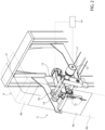
Figures 2 and3 are perspective views, with parts removed for clarity, of a printing system of the packaging machine ofFigure 1 ; and -
Figure 4 is a top view, with parts removed for clarity, of a pillow pack produced with the packaging machine ofFigure 1 . - With reference to
Figure 1 ,number 1 indicates as a whole a non-limiting example of a packaging machine configured to produce sealedpackages 2 containing a pourable product, preferably a pourable food product such as pasteurized or UHT milk, water, fruit juice, wine, peas, beans, etc. - In detail,
packaging machine 1 is configured to form, seal andfold packages 2 starting from aweb 4 of packaging material, which is initially wound in areel 4a, and then folded into atube 3 of packaging material, as explained below. - Preferably,
packaging machine 1 is part of a packaging line (known per se and not shown) configured for producing, grouping and boxing a plurality of packages in a known manner. - As schematized in
Figure 1 ,packaging machine 1 comprises: - conveying means configured to advance
web 4 along an advancement path P; - a
tube folding device 5 configured to progressively foldweb 4 into atube 3; - a
sealing element 40 for longitudinallyseal tube 3, in a manner known and not described in detail; - a
filling device 7 for filling tube 3 (from above) with the pourable product; - a forming and
sealing unit 6 configured to formtube 3 andseal tube 3 along successive transversal cross-sections thereof in order to obtain a sequence ofpillow packs 2a, in a manner known and not described in detail; - an isolation chamber 8 internally defining an environment containing a controlled atmosphere, in particular sterile and/or aseptic gas, preferably sterile and/or aseptic air, and housing the forming and
sealing unit 6, thetube folding device 5, thesealing element 40 and thefilling device 7; - a folding device (not shown) configured to sequentially fold
packs 2a in order to obtain a plurality of sealedpackages 2. -
Tube folding device 5 andsealing element 40 define together a tube forming unit. - Preferably, forming and sealing
unit 6 has an axis X along whichtube 3 is fed, in use. - Axis X is parallel to a straight direction, which preferably is a straight vertical direction.
- Hence, in use,
tube 3 is fed along axis X, downwards, and while being filled from above is formed and sealed by forming and sealingunit 6. - More specifically,
tube 3 is drawn (downwards) along axis X by forming and sealingunit 6 in a known manner. - In this way, a plurality of
pillow packs 2a are obtained. - In light of the above,
packaging machine 1 is configured to form and seal a plurality ofpillow packs 2a containing the pourable product starting fromweb 4 andtube 3 and then to fold thepillow packs 2a for obtaining the aforementioned formed, sealed and foldedpackages 2 containing the pourable product. - As visible in
Figure 4 ,pillow packs 2a have amain body 41, with alongitudinal sealing band 42 longitudinally extending alongmain body 41 and two oppositetransversal sealing bands 43, one at each longitudinal end portion of thepack 2a. - Preferably,
packaging machine 1 also comprises a discarding or sorting device (of the type known and not shown) configured to discard or sort the packs, e.g. by sampling the produced packs. The discarding or sorting device may be positioned downstream of the forming and sealingunit 6. - The discarding device is configured to discard
packs 2a, such aspacks 2a having a shape, weight, or sealing deviating from the desired ones or packs that are sampled for testing purposes. -
Packaging machine 1 further comprises aprinting system 11 comprising aprinter device 12 configured to sequentially print codes 13 (Figures 2 and4 ) on the packaging material. - According to a preferred embodiment,
printer device 12 is configured toprint codes 13 containing information/data correlated with production events or with the production process. - For example, each
code 13 may contain information and/or data such as a specific (sequential) production lot number or an expiration date. - For example, each
code 13 may contain information and/or data indicative of the settings and/or parameters of the components of thepackaging machine 1 interacting with theweb 4, such as the folding andsealing unit 6. - According to one aspect of the present invention,
printer device 12 is arranged along advancement path P in a position operatively upstream of forming and sealingunit 6, and is configured to printcodes 13 directly onweb 4. - More in particular, as visible in
Figure 1 ,printer device 12 is arranged in a position operatively upstream of tube forming unit (and in detail upstream of tube folding device 5) with respect to advancement path P, forprinting codes 13 directly onweb 4 prior to the folding ofweb 4 intotube 3. - In other words,
printer device 12 is configured to sequentiallyprint codes 13 on the unfoldedweb 4, i.e. directly onweb 4 beforeweb 4 is folded intotube 3. - Thanks to this configuration, every
pack 2a will have acode 13 printed thereon, sincecodes 13 are provided on the packaging material still in form of web, and therefore beforeweb 4 is transformed into a plurality ofpacks 2a. - In this way, a number of
packs 2a discarded by the discarding device may be successfully identified. - This is particularly advantageous during tests, during which the
packs 2a (sometimes faulty) may be sampled and tested, the packs providing useful information and data about the test itself. - Advantageously, thanks to the
instant printer device 12, all packs can be identified correctly. That is, due to the printing being performed on theweb 4, it is possible to control accurately the printing process. Conveniently,packaging machine 1 comprises acontrol unit 14 configured to control the operation of the conveying means, of tube forming unit, of forming and sealingunit 6 and of the folding device. - Advantageously,
control unit 14 is further configured to control the operation ofprinting system 11, i.e. ofprinter device 12. - Expediently,
control unit 14 is further configured to directly send toprinter device 12 signals/data correlated withcodes 13 to be printed. - Advantageously, the control of the printing system can be performed directly by the packaging machine, e.g. adapting dynamically to transients and events.
- According to a further aspect of the present invention,
printing system 11 further comprises asensor device 15 configured to detect a speed (and in particular an advancing speed) ofweb 4 along advancement path P. Accordingly,control unit 14 is configured to receive from sensor device 15 a speed signal indicative of the detected speed and to control the operation ofprinter device 12 as a function of such speed signal. - In one embodiment,
control unit 14 is configured to adjust a printing cadence ofprinter device 12 as a function of the speed signal. - In one embodiment,
control unit 14 is configured to control a movement ofprinter device 12 towards and away from web 4 (i.e. from advancement path P) as a function of the speed signal for adjusting a distance ofprinter device 12 from web 4 (i.e. from advancement path P). - According to the preferred and non-limiting embodiment shown,
sensor device 15 includes (Figures 2 and3 ) : - a
roller 16 configured to rotatably abut againstweb 4 and to cooperate in contact withweb 4 so as to convey theweb 4, e.g. theroller 16 can be actuated in rotation by the advancement ofweb 4; and - an
encoder 17 coupled withroller 16 and configured to detect a speed ofweb 4 by means of the rotation of roller 16 (which, as said, is caused by the advancement of web 4). - Thanks to the presence of
sensor device 15, a direct synchronization ofprinter device 12 withweb 4 is provided, which is easier to manage, more reliable and less prone to errors than a synchronization made between a printing unit and thefinished packages 2, as it is the case in the prior art configurations. - In fact,
sensor device 15 provides a better and direct synchronization ofprinter device 12 withweb 4, as the chain of errors and tolerances is shorter than the one betweenfinished packages 2 and a printing unit arranged downstream of the folding device, as it is the case in the prior art configurations. - Preferably,
sensor device 15 further comprises a counter-roller 18 configured to abut againstroller 16, with the interposition onweb 4. - In this way, the detection performed by
encoder 17 can better adapt to possible fluctuations in the packaging material thickness or speed, thereby further improving the synchronization betweenweb 4 andprinter device 12. - Advantageously, roller 16 (and therefore also counter-roller 18) is arranged in a position adjacent to
printer device 12, so as to define a detection area on the advancingweb 4 that is located adjacent toprinter device 12. - The Applicant has observed that such positioning of
roller 16 provides the most accurate speed detection, at an area close to where the printing is carried out, thereby minimizing the effect of possible events, undertensioning and/or overtensioning ofweb 4 on the speed detection, and shortening the chain of error. - As schematized in
Figure 2 ,web 4 consists ofweb portions 4b. - Hence, the conveying means are configured to advance a sequence of
web portions 4b defining theweb 4, eachweb portion 4b being apt to define arespective package 2 after the forming, sealing and folding thereof. - Conveniently,
control unit 14 is further configured to carry out a tracking of eachweb portion 4b, and then of eachpillow pack 2a andpackage 2, along thepackaging machine 1. - More specifically,
control unit 14 is configured to carry out a method for tracking eachweb portion 4b,pack 2a, orpackage 2 as described in theItalian Patent Application No. 102023000007410 - According to an alternative embodiment not shown,
sensor device 15 may comprise a detector (not shown) configured to sequentially detect data carriers onweb 4, each data carrier being indicative of the position and/or speed of arespective web portion 4b, the detector being configured to send to controlunit 14 signals correlated with each detection. - For example, the data carriers may be defined by markers such as optical marks or magnetic marks.
- Accordingly, the detector includes an optical detector for optically detecting the data carriers, or a magnetic detector for magnetically detecting the data carriers, depending on the nature of the data carriers.
- Expediently, the detector is arranged along the advancement path P in a position operatively upstream of
printer device 12. - The above configuration allows for reducing wear on the packaging material, compared to the
sensor device 15 withencoder 17 androller 16, albeit being less accurate than the roller-encoder system described above. - As schematized in
Figure 1 ,packaging machine 1 further comprises asterilization unit 19 arranged along advancement path P in a position upstream oftube folding device 5 and configured to perform a sterilizing treatment onweb 4. - Advantageously,
printer device 12 is arranged in a position upstream ofsterilization unit 19, with respect to advancement path P, forprinting codes 13 directly onweb 4 prior to its sterilization. - In this way, even the printed
code 13, which may consist of ink, is sterilized together with the packaging material. - In one embodiment,
sterilization unit 19 includes an electron-beam sterilizer of the type known, configured to irradiateweb 4 with a beam of electrons. - By arranging
printer device 12 upstream of such sterilizer, it is ensured thatcodes 13 are cured by the electron beam, i.e.codes 13 are well-dried on the packaging material, other than being sterilized. - In one embodiment,
printer device 12 is an inkjet printer. - In one embodiment,
printer device 12 is a laser printer. In such a case, there is no need for any ink to dry. - As said, each
pack 2a has amain body 41, with alongitudinal sealing band 42 longitudinally extending alongmain body 41 and two oppositetransversal sealing bands 43, one at each longitudinal end portion of thepack 2a, as shown inFigure 4 . - Advantageously,
printer device 12 is configured to print a pair ofcodes 13 on eachweb portion 4b, so that afirst code 13a is located at a part of theweb portion 4b corresponding to afirst end 41a of therespective pack 2a orpackage 2 proximal to afirst sealing band 43 thereof, and asecond code 13b is located at another part of theweb portion 4b corresponding to asecond end 41b of therespective pack 2a orpackage 2 proximal to asecond sealing band 43 thereof. - This condition is shown in
Figure 4 . - Thanks to this feature, tracking and identification of
packs 2a andpackages 2, especially during tests, is largely improved. In fact, in some cases packs 2a orpackages 2 are cut in half during tests. Having aunique code 13 in each respective half allows for better detecting to whichpack 2a orpackage 2 the cut half belongs. - The control unit may be configured to receive an event signal indicative of an event occurring in the packaging machine. For example, such event comprises a splice, i.e. a joining of the web of packaging material with a new web belonging to a new reel.
- The control unit may be configured to adjust a control of the
printer device 12 as a function of the event signal, preferably varying the printing cadence and/orprinting codes 13 indicative of said event. For example, thecodes 13 may comprise information on the event. - In case of a splice, the
code 13 printed on the packages may comprise such splice, in order to identify theweb portions 4b in proximity thereof, e.g. the web portion affected by the splice and the neighboring ones. - According to a further aspect of the present invention,
printer device 12 andsensor device 15, i.e.printing system 11, are configured to be implemented inpackaging machine 1 in a removable manner, so as to define a removable printing kit for packagingmachine 1. - In other words,
printing system 11 according to the present invention advantageously defines a removable printing kit adapted to be implemented inpackaging machine 1, the removable printing kit comprising: - a
printer device 12, configured to be removably arranged along advancement path P in a position operatively upstream of forming and sealingunit 6, preferably upstream of the tube forming unit, even more preferably upstream ofsterilization unit 19, forprinting codes 13 directly onweb 4; and - a
sensor device 15 coupled toprinter device 12, configured to be removably arranged along advancement path P and configured to interact with the advancingweb 4 for detecting a speed ofweb 4 along advancement path P and to controlprinter device 12 based on said detection. - Furthermore,
printing system 11 according to the present invention allows to implement a method for the production ofpackages 2 containing a pourable product starting from aweb 4 of packaging material, the method comprising the steps of: - advancing the
web 4 along an advancement path P; - folding the
web 4 into atube 3; - longitudinally sealing the
tube 3; - filling the
tube 3 with the pourable product; - forming and transversally sealing the
tube 3 so as to obtain a plurality ofpacks 2a; - folding the
packs 2a to obtain a plurality ofpackages 2; - sequentially
printing codes 13 on the packaging material; - Conveniently, the method comprises the steps of:
- detecting a speed of the web along the advancement path;
- controlling the step of sequentially
printing codes 13 as a function of the speed detected during the step of detecting. - The advantages of
packaging machine 1, the removable printing kit and the method according to the present invention will be clear from the foregoing description. - In particular, as
codes 13 are printed on the packaging material in form ofweb 4, and therefore beforeweb 4 is turned into a plurality ofpacks 2a, everypack 2a andpackage 2 will have one ormore codes 13 printed thereon. - In this way, even if
packs 2a are discarded by the discarding or sorting device, it is possible to successfully identify them. This is particularly advantageous during tests, during which thepacks 2a (sometimes faulty) may provide useful information and data about the test itself. - Advantageously, thanks to the printing system 11 a correct identification of the packages is possible also in case of events, transients or variations in the tensioning of the web.
- Furthermore, thanks to the presence of
sensor device 15 as described above, a direct synchronization ofprinter device 12 withweb 4 is provided, which is easier to manage, more reliable and less prone to errors than a synchronization made between a printing unit and thefinished packages 2, as it is the case in the prior art configurations. In fact,sensor device 15 provides a better and direct synchronization ofprinter device 12 withweb 4, as the chain of errors and tolerances is shorter than the one betweenfinished packages 2 and a printing unit arranged downstream the folding device, as it is the case in the prior art configurations. - Clearly, changes may be made to
packaging machine 1, the removable printing kit and the related method as described herein without, however, departing from the scope of protection as defined in the accompanying claims.
Claims (16)
- Packaging machine (1) configured for producing sealed packages (2) containing a pourable product starting from a web (4) of packaging material, the packaging machine (1) comprising:- conveying means configured to advance the web (4) along an advancement path (P);- a tube forming unit (5, 40) configured to fold the web (4) into a tube (3) and to longitudinally seal the tube (3);- a forming and sealing unit (6) configured to form the tube (3) and seal the tube (3) along successive transversal cross-sections thereof in order to obtain a sequence of packs (2a);- a folding device configured to sequentially fold the packs (2a) in order to obtain a plurality of sealed packages (2); and- a printing system (11) comprising a printer device (12) configured to sequentially print codes (13) on the packaging material;wherein the printer device (12) is arranged along the advancement path (P) in a position operatively upstream of the forming and sealing unit (6), and is configured to print said codes (13) directly on the web (4) .
- Packaging machine as claimed in claim 1, wherein the printer device (12) is arranged in a position operatively upstream of the tube forming unit (5, 40), with respect to the advancement path (P), for printing said codes (13) directly on the web (4) prior to the folding of the web (4) into said tube (3).
- Packaging machine as claimed in claim 1 or 2, wherein the printing system (11) further comprises a sensor device (15) configured to detect a speed of the web (4) along the advancement path (P);
and wherein the packaging machine (1) further comprises a control unit (14) configured to receive from the sensor device (15) a speed signal indicative of the detected speed, and to control the operation of the printer device (12) as a function of the speed signal. - Packaging machine as claimed in claim 3, wherein the control unit (14) is configured to adjust a printing cadence of the printer device (12) as a function of the speed signal.
- Packaging machine as claimed in claim 3 or 4, wherein the control unit (14) is configured to control a movement of the printer device (12) towards and away from the web (4) as a function of the speed signal for adjusting a distance of the printer device (12) from the web (4).
- Packaging machine as claimed in any one of the claims 3 to 5, wherein the sensor device (15) includes:- a roller (16) configured to rotatably abut against the web (4) and to cooperate in contact with the web (4) so as to be actuated in rotation by the advancement of the web (4); and- an encoder (17) coupled with the roller (16) and configured to detect a speed of the web (4) by means of the rotation of the roller (16).
- Packaging machine as claimed in claim 6, wherein the roller (16) is arranged in a position adjacent to the printer device (12), so as to define a detection area on the advancing web (4) that is located adjacent to the printer device (12).
- Packaging machine as claimed in any of claims 3 to 7, wherein the sensor device (15) comprises a detector configured to sequentially detect data carriers on the web (4), each data carrier being indicative of the position and/or speed of a respective web portion (4b) which is apt to define a respective pack (2a), the detector being configured to send to the control unit (14) signals correlated with each detection;
and wherein the detector is arranged along the advancement path (P) in a position operatively upstream of the printer device (12). - Packaging machine as claimed in any of the foregoing claims and comprising a control unit (14) configured to control the operation of the conveying means, of the tube forming unit (5, 40), of the forming and sealing unit (6) and of the folding device;
and wherein the control unit (14) is further configured to control the operation of the printing system (11) . - Packaging machine as claimed in claim 9, wherein the control unit (14) is further configured to:- receive data indicative of operation of the conveying means, of the tube forming unit (5, 40), of the forming and sealing unit (6) and/or of the folding device, and- printing said codes (13) as a function of said data.
- Packaging machine as claimed in any of the foregoing claims, and comprising a sterilization unit (19) arranged along the advancement path (P) in a position upstream of the tube forming device (5, 40) and configured to perform a sterilizing treatment on the web (4);
wherein the printer device (12) is arranged in a position upstream of the sterilization unit (19), with respect to the advancement path (P), for printing said codes (13) directly on the web (4) prior to its sterilization. - Packaging machine as claimed in any one of the foregoing claims, wherein the conveying means are configured to advance a sequence of web portions (4b) defining said web (4), each web portion (4b) being apt to define a respective package (2) after the forming, sealing and folding thereof, each package (2) having a main body (41) longitudinally delimited by two opposite sealing bands (43);
wherein the printer device (12) is configured to print a plurality of said codes (13) on each web portion (4b), preferably so that a first code (13a) is located at a part of the web portion (4b) corresponding to a first end (41a) of the respective package (2) proximal to a first sealing band (43) thereof, and a second code (13b) is located at another part of the web portion (4b) corresponding to a second end (41b) of the respective package (2) proximal to a second sealing band (43) thereof. - Packaging machine as claimed in claim 3 or 8, wherein the printer device (12) and the sensor device (15) are configured to be implemented in the packaging machine (1) in a removable manner, so as to define a removable printing kit for the packaging machine (1).
- Removable printing kit adapted to be implemented in a packaging machine (1) configured for producing sealed packages (2) containing a pourable product starting from a web (4) of packaging material, the packaging machine (1) comprising a conveying device configured to advance the web (4) along an advancement path (P), a tube forming device (5, 40) configured to fold the web (4) into a tube (3) and to longitudinally seal the tube (3), a forming and sealing unit (6) configured to form the tube (3) and seal the tube (3) along successive transversal cross-sections thereof in order to obtain a sequence of packs (2a), and a folding device configured to sequentially fold the packs (2a) in order to obtain sealed packages (2), the printing kit being removably couplable to the packaging machine (1) and comprising:- a printer device (12) configured to sequentially print codes (13) on the packaging material and to be removably arranged along the advancement path (P) in a position operatively upstream of the forming and sealing unit (6) for printing said codes (13) directly on the web (4); and- a sensor device (15) coupled to the printer device (12), configured to be removably arranged along the advancement path (P) and configured for detecting a speed of the web (4) along the advancement path (P) and to control the printer device (12) based on said detection.
- Method for the production of packages (2) containing a pourable product starting from a web (4) of packaging material, the method comprising the steps of:- advancing the web (4) along an advancement path (P) ;- folding the web (4) into a tube (3);- longitudinally sealing the tube (3);- filling the tube (3) with the pourable product;- forming and transversally sealing the tube (3) so as to obtain a plurality of packs (2a);- folding the packs (2a) to obtain a plurality of packages (2);- sequentially printing codes (13) on the packaging material;wherein the step of printing comprises printing the codes (13) directly on the web (4), prior to the step of folding the web (4).
- Method as claimed in claim 15, and comprising the steps of:- detecting a speed of the web (4) along the advancement path (P);- controlling the step of sequentially printing codes (13) as a function of the speed detected during the step of detecting.
Applications Claiming Priority (1)
| Application Number | Priority Date | Filing Date | Title |
|---|---|---|---|
| IT102023000025584A IT202300025584A1 (en) | 2023-11-30 | 2023-11-30 | PACKAGING MACHINE CONFIGURED TO PRODUCE SEALED PACKAGES CONTAINING A POURABLE PRODUCT, REMOVABLE PRINTING KIT AND METHOD FOR PRODUCING PACKAGES CONTAINING A POURABLE PRODUCT |
Publications (1)
| Publication Number | Publication Date |
|---|---|
| EP4563481A1 true EP4563481A1 (en) | 2025-06-04 |
Family
ID=90363258
Family Applications (1)
| Application Number | Title | Priority Date | Filing Date |
|---|---|---|---|
| EP24214060.6A Pending EP4563481A1 (en) | 2023-11-30 | 2024-11-20 | Packaging machine configured to produce sealed packages containing a pourable product, removable printing kit for such packaging machine and method for producing packages containing a pourable product |
Country Status (3)
| Country | Link |
|---|---|
| EP (1) | EP4563481A1 (en) |
| IT (1) | IT202300025584A1 (en) |
| WO (1) | WO2025114097A1 (en) |
Citations (2)
| Publication number | Priority date | Publication date | Assignee | Title |
|---|---|---|---|---|
| JPH08217039A (en) * | 1995-02-20 | 1996-08-27 | Taisei Kikai:Kk | Printing method in packing machine |
| WO1997024278A1 (en) * | 1995-12-29 | 1997-07-10 | Tetra Laval Holding & Finance S.A. | Packaging material with invisible information |
-
2023
- 2023-11-30 IT IT102023000025584A patent/IT202300025584A1/en unknown
-
2024
- 2024-11-20 WO PCT/EP2024/082908 patent/WO2025114097A1/en active Pending
- 2024-11-20 EP EP24214060.6A patent/EP4563481A1/en active Pending
Patent Citations (2)
| Publication number | Priority date | Publication date | Assignee | Title |
|---|---|---|---|---|
| JPH08217039A (en) * | 1995-02-20 | 1996-08-27 | Taisei Kikai:Kk | Printing method in packing machine |
| WO1997024278A1 (en) * | 1995-12-29 | 1997-07-10 | Tetra Laval Holding & Finance S.A. | Packaging material with invisible information |
Also Published As
| Publication number | Publication date |
|---|---|
| IT202300025584A1 (en) | 2025-05-30 |
| WO2025114097A1 (en) | 2025-06-05 |
Similar Documents
| Publication | Publication Date | Title |
|---|---|---|
| KR101429787B1 (en) | A process for producing a sealed packaging container for storing a liquid food product and a packaging device for carrying out such a process | |
| US12060191B2 (en) | Packaging machine and method for producing sealed packages | |
| US11434028B2 (en) | Method and an apparatus for applying a sealing strip to a web of packaging material | |
| EP1441954B1 (en) | Sheet material for producing packages of food products, and packages made of such material | |
| EP4335758A1 (en) | Packaging machine and method for producing packages from a packaging material | |
| US20040259709A1 (en) | Packaging sheet material for packaging pourable food products | |
| WO2025114097A1 (en) | Packaging machine configured to produce sealed packages containing a pourable product, removable printing kit for such packaging machine and method for producing packages containing a pourable product | |
| US11434097B2 (en) | Magazine unit for a packaging machine, packaging machine having a magazine unit and method for loading a magazine unit | |
| EP4592777A1 (en) | Method and apparatus for performing operations on a packaging material | |
| US12103262B2 (en) | Unit and method for applying opening devices to a web of packaging material | |
| WO2022078753A1 (en) | Pressure element and sealing device for a packaging assembly having a pressure element |
Legal Events
| Date | Code | Title | Description |
|---|---|---|---|
| PUAI | Public reference made under article 153(3) epc to a published international application that has entered the european phase |
Free format text: ORIGINAL CODE: 0009012 |
|
| STAA | Information on the status of an ep patent application or granted ep patent |
Free format text: STATUS: THE APPLICATION HAS BEEN PUBLISHED |
|
| AK | Designated contracting states |
Kind code of ref document: A1 Designated state(s): AL AT BE BG CH CY CZ DE DK EE ES FI FR GB GR HR HU IE IS IT LI LT LU LV MC ME MK MT NL NO PL PT RO RS SE SI SK SM TR |
|
| STAA | Information on the status of an ep patent application or granted ep patent |
Free format text: STATUS: REQUEST FOR EXAMINATION WAS MADE |
|
| 17P | Request for examination filed |
Effective date: 20251204 |