EP4563474A1 - Vertiport system including transfer apparatus using cable - Google Patents
Vertiport system including transfer apparatus using cable Download PDFInfo
- Publication number
- EP4563474A1 EP4563474A1 EP24169163.3A EP24169163A EP4563474A1 EP 4563474 A1 EP4563474 A1 EP 4563474A1 EP 24169163 A EP24169163 A EP 24169163A EP 4563474 A1 EP4563474 A1 EP 4563474A1
- Authority
- EP
- European Patent Office
- Prior art keywords
- cable
- aircraft
- motor
- area
- transfer
- Prior art date
- Legal status (The legal status is an assumption and is not a legal conclusion. Google has not performed a legal analysis and makes no representation as to the accuracy of the status listed.)
- Granted
Links
Images



Classifications
-
- B—PERFORMING OPERATIONS; TRANSPORTING
- B64—AIRCRAFT; AVIATION; COSMONAUTICS
- B64F—GROUND OR AIRCRAFT-CARRIER-DECK INSTALLATIONS SPECIALLY ADAPTED FOR USE IN CONNECTION WITH AIRCRAFT; DESIGNING, MANUFACTURING, ASSEMBLING, CLEANING, MAINTAINING OR REPAIRING AIRCRAFT, NOT OTHERWISE PROVIDED FOR; HANDLING, TRANSPORTING, TESTING OR INSPECTING AIRCRAFT COMPONENTS, NOT OTHERWISE PROVIDED FOR
- B64F1/00—Ground or aircraft-carrier-deck installations
- B64F1/22—Ground or aircraft-carrier-deck installations for handling aircraft
-
- B—PERFORMING OPERATIONS; TRANSPORTING
- B64—AIRCRAFT; AVIATION; COSMONAUTICS
- B64F—GROUND OR AIRCRAFT-CARRIER-DECK INSTALLATIONS SPECIALLY ADAPTED FOR USE IN CONNECTION WITH AIRCRAFT; DESIGNING, MANUFACTURING, ASSEMBLING, CLEANING, MAINTAINING OR REPAIRING AIRCRAFT, NOT OTHERWISE PROVIDED FOR; HANDLING, TRANSPORTING, TESTING OR INSPECTING AIRCRAFT COMPONENTS, NOT OTHERWISE PROVIDED FOR
- B64F1/00—Ground or aircraft-carrier-deck installations
- B64F1/12—Ground or aircraft-carrier-deck installations for anchoring aircraft
- B64F1/125—Mooring or ground handling devices for helicopters
-
- B—PERFORMING OPERATIONS; TRANSPORTING
- B64—AIRCRAFT; AVIATION; COSMONAUTICS
- B64F—GROUND OR AIRCRAFT-CARRIER-DECK INSTALLATIONS SPECIALLY ADAPTED FOR USE IN CONNECTION WITH AIRCRAFT; DESIGNING, MANUFACTURING, ASSEMBLING, CLEANING, MAINTAINING OR REPAIRING AIRCRAFT, NOT OTHERWISE PROVIDED FOR; HANDLING, TRANSPORTING, TESTING OR INSPECTING AIRCRAFT COMPONENTS, NOT OTHERWISE PROVIDED FOR
- B64F1/00—Ground or aircraft-carrier-deck installations
- B64F1/22—Ground or aircraft-carrier-deck installations for handling aircraft
- B64F1/223—Ground or aircraft-carrier-deck installations for handling aircraft for towing aircraft
- B64F1/225—Vehicles specially adapted therefor, e.g. aircraft tow tractors
- B64F1/228—Vehicles specially adapted therefor, e.g. aircraft tow tractors remotely controlled; operating autonomously
-
- B—PERFORMING OPERATIONS; TRANSPORTING
- B64—AIRCRAFT; AVIATION; COSMONAUTICS
- B64F—GROUND OR AIRCRAFT-CARRIER-DECK INSTALLATIONS SPECIALLY ADAPTED FOR USE IN CONNECTION WITH AIRCRAFT; DESIGNING, MANUFACTURING, ASSEMBLING, CLEANING, MAINTAINING OR REPAIRING AIRCRAFT, NOT OTHERWISE PROVIDED FOR; HANDLING, TRANSPORTING, TESTING OR INSPECTING AIRCRAFT COMPONENTS, NOT OTHERWISE PROVIDED FOR
- B64F1/00—Ground or aircraft-carrier-deck installations
- B64F1/02—Ground or aircraft-carrier-deck installations for arresting aircraft, e.g. nets or cables
- B64F1/029—Ground or aircraft-carrier-deck installations for arresting aircraft, e.g. nets or cables using a cable or tether
-
- B—PERFORMING OPERATIONS; TRANSPORTING
- B64—AIRCRAFT; AVIATION; COSMONAUTICS
- B64F—GROUND OR AIRCRAFT-CARRIER-DECK INSTALLATIONS SPECIALLY ADAPTED FOR USE IN CONNECTION WITH AIRCRAFT; DESIGNING, MANUFACTURING, ASSEMBLING, CLEANING, MAINTAINING OR REPAIRING AIRCRAFT, NOT OTHERWISE PROVIDED FOR; HANDLING, TRANSPORTING, TESTING OR INSPECTING AIRCRAFT COMPONENTS, NOT OTHERWISE PROVIDED FOR
- B64F1/00—Ground or aircraft-carrier-deck installations
- B64F1/12—Ground or aircraft-carrier-deck installations for anchoring aircraft
- B64F1/16—Pickets or ground anchors; Wheel chocks
-
- B—PERFORMING OPERATIONS; TRANSPORTING
- B64—AIRCRAFT; AVIATION; COSMONAUTICS
- B64F—GROUND OR AIRCRAFT-CARRIER-DECK INSTALLATIONS SPECIALLY ADAPTED FOR USE IN CONNECTION WITH AIRCRAFT; DESIGNING, MANUFACTURING, ASSEMBLING, CLEANING, MAINTAINING OR REPAIRING AIRCRAFT, NOT OTHERWISE PROVIDED FOR; HANDLING, TRANSPORTING, TESTING OR INSPECTING AIRCRAFT COMPONENTS, NOT OTHERWISE PROVIDED FOR
- B64F1/00—Ground or aircraft-carrier-deck installations
- B64F1/22—Ground or aircraft-carrier-deck installations for handling aircraft
- B64F1/223—Ground or aircraft-carrier-deck installations for handling aircraft for towing aircraft
-
- B—PERFORMING OPERATIONS; TRANSPORTING
- B64—AIRCRAFT; AVIATION; COSMONAUTICS
- B64F—GROUND OR AIRCRAFT-CARRIER-DECK INSTALLATIONS SPECIALLY ADAPTED FOR USE IN CONNECTION WITH AIRCRAFT; DESIGNING, MANUFACTURING, ASSEMBLING, CLEANING, MAINTAINING OR REPAIRING AIRCRAFT, NOT OTHERWISE PROVIDED FOR; HANDLING, TRANSPORTING, TESTING OR INSPECTING AIRCRAFT COMPONENTS, NOT OTHERWISE PROVIDED FOR
- B64F1/00—Ground or aircraft-carrier-deck installations
- B64F1/22—Ground or aircraft-carrier-deck installations for handling aircraft
- B64F1/24—Adaptations of turntables
-
- B—PERFORMING OPERATIONS; TRANSPORTING
- B64—AIRCRAFT; AVIATION; COSMONAUTICS
- B64F—GROUND OR AIRCRAFT-CARRIER-DECK INSTALLATIONS SPECIALLY ADAPTED FOR USE IN CONNECTION WITH AIRCRAFT; DESIGNING, MANUFACTURING, ASSEMBLING, CLEANING, MAINTAINING OR REPAIRING AIRCRAFT, NOT OTHERWISE PROVIDED FOR; HANDLING, TRANSPORTING, TESTING OR INSPECTING AIRCRAFT COMPONENTS, NOT OTHERWISE PROVIDED FOR
- B64F1/00—Ground or aircraft-carrier-deck installations
- B64F1/36—Other airport installations
-
- B—PERFORMING OPERATIONS; TRANSPORTING
- B66—HOISTING; LIFTING; HAULING
- B66D—CAPSTANS; WINCHES; TACKLES, e.g. PULLEY BLOCKS; HOISTS
- B66D1/00—Rope, cable, or chain winding mechanisms; Capstans
- B66D1/28—Other constructional details
- B66D1/40—Control devices
- B66D1/48—Control devices automatic
- B66D1/50—Control devices automatic for maintaining predetermined rope, cable, or chain tension, e.g. in ropes or cables for towing craft, in chains for anchors; Warping or mooring winch-cable tension control
Definitions
- the present disclosure relates to a vertiport system including a transfer apparatus using a cable.
- a UAM vehicle may be an aircraft capable of vertical takeoff and landing flight.
- the development of a vertiport, a UAM vehicle takeoff/landing site, has been required along with the development of a UAM vehicle.
- a vertiport may include infrastructure or systems with support services and equipment for landing, ground handling, and takeoff of manned or unmanned vertical takeoff and landing (VTOL) aircrafts.
- the vertiport may be generally considered to be installed on the rooftops of high-rise buildings or in large parks.
- the vertiport may have a smaller footprint with smaller landing and takeoff regions, as compared to a typical airport with general runways.
- UAM vehicles may require taxiing for various purposes such as passenger boarding and disembarking/charging/parking/hangar transfer within a vertiport.
- Embodiments of the present disclosure provide a vertiport system capable of rapidly and stably transferring an aircraft along a predetermined transfer path within a vertiport and stably fixing the aircraft during transfer and parking of the aircraft.
- a vertiport system including a first area, a second area provided in a position different from that of the first area, and a transfer portion configured to transfer an aircraft between the first area and the second area.
- the transfer portion may include a front transfer unit having a front cable detachably connected to a front portion of the aircraft and a rear transfer unit having a rear cable detachably connected to a rear portion of the aircraft.
- the front cable may be configured to be detachably connected to a nose landing gear member of the aircraft.
- the rear cable may be configured to be detachably connected to a main landing gear member of the aircraft.
- the rear transfer unit may include a first rear transfer unit and a second rear transfer unit respectively connected to two main landing gear members provided in the aircraft.
- the rear cable may include a first rear cable provided in the first rear transfer unit and a second rear cable provided in the second rear transfer unit.
- the front transfer unit may further include a front motor to which the front cable is connected, the front motor being configured to provide a predetermined degree of tension force to the front cable.
- the first rear transfer unit may further include a first rear motor to which the first rear cable is connected, the first rear motor being configured to provide a predetermined degree of tension force to the first rear cable.
- the second rear transfer unit may further include a second rear motor to which the second rear cable is connected, the second rear motor being configured to provide a predetermined degree of tension force to the second rear cable.
- the transfer portion may be configured to generate a predetermined degree of tension force or traction force in at least one of the front cable, the first rear cable, and the second rear cable by driving the front motor, the first rear motor, and the second rear motor in a state in which the front cable, the first rear cable, and the second rear cable are connected to the aircraft.
- the front transfer unit may be disposed in the first area.
- the first rear transfer unit and the second rear transfer unit may be disposed in the second area.
- the aircraft may be transferred between the first area and the second area by driving the front motor, the first rear motor, and the second rear motor in a state in which the front cable, the first rear cable, and the second rear cable are connected thereto.
- the vertiport system may further include a motor controller configured to control the front motor, the first rear motor, and the second rear motor.
- the motor controller may be set to move the aircraft in a rectilinear direction by collaboratively controlling the front motor, the first rear motor, and the second rear motor.
- the motor controller may be set to detect tension force information of the front cable, the first rear cable, and the second rear cable, and to control, based on the detected tension force information, the front motor, the first rear motor, and the second rear motor.
- Each of the front motor, the first rear motor, and the second rear motor may include a sensor configured to measure the tension force information and a communication module configured to transmit the tension force information to the motor controller.
- the rectilinear direction may be a direction parallel to an imaginary straight line connecting a center of the first area and a center of the second area to each other.
- the first area may be a transfer area configured to transfer the aircraft to another area or a facility.
- the second area may be a takeoff and landing area provided for takeoff and landing of the aircraft.
- At least one of the first area and the second area may be configured to be rotatable.
- the vertiport system may further include a control center configured to control takeoff, landing, stopping, or transfer of the aircraft and to provide control information.
- a method of transferring an aircraft in a vertiport system including landing, by an aircraft, in a takeoff and landing area, connecting a front cable and a rear cable to a landing gear member of the aircraft, transferring the aircraft to a transfer area by driving a front motor to which the front cable is connected and a rear motor to which the rear cable is connected, and disconnecting the front cable and the rear cable from the landing gear member.
- the front cable may be connected to a nose landing gear member of the aircraft.
- the rear cable may include a first rear cable and a second rear cable connected to two main landing gear members of the aircraft.
- the rear motor may include a first rear motor corresponding to the first rear cable and a second rear motor corresponding to the second rear cable.
- a predetermined degree of tension force or traction force may be formed in at least one of the front cable, the first rear cable, and the second rear cable by driving the front motor, the first rear motor, and the second rear motor.
- the aircraft In the transferring the aircraft by driving the motor, the aircraft may be moved in a rectilinear direction by collaboratively controlling the front motor, the first rear motor, and the second rear motor.
- the transferring the aircraft by driving the motor may include detecting tension force information of the front cable, the first rear cable, and the second rear cable and controlling, based on the detected tension force information, the front motor, the first rear motor, and the second rear motor.
- an aircraft may be stably transferred and fixed within a vertiport by connecting a cable to a landing gear member of the aircraft, thereby preventing the aircraft from being greatly shaken or overturned by strong winds during transfer and parking of the aircraft.
- equipment such as a tug car may not be used for transfer of an aircraft, thereby reducing air pollution and noise pollution, and stably and efficiently performing a transfer.
- first, second, A, B, (a), (b), and the like may be used herein to describe components. Each of these terminologies is not used to define an essence, order, or sequence of a corresponding component but is used merely to distinguish the corresponding component from other component(s).
- a first component may be referred to as a second component, and similarly the second component may also be referred to as the first component.
- the term "and/or" may include combinations of a plurality of related described items or any of a plurality of related described items.
- An aircraft may refer to a mobility vehicle capable of moving by flying in the sky. That is, the aircraft, in addition to referring to a helicopter, drone, tilt rotor, fixed-wing airplane, and the like, may include vehicles capable of flying in a state in which the vehicles move on the ground using wheels, and the wheels are separated from the ground.
- the aircraft may include a manned aircraft and an unmanned aircraft.
- the manned aircraft may include an airframe capable of operating autonomously in addition to an airframe controlled by a pilot.
- FIG. 1 illustrates a vertiport system 100 according to an example embodiment of the present disclosure.
- FIG. 2 illustrates rear transfer units 140 and 150 of the vertiport system 100 according to an example embodiment of the present disclosure.
- FIG. 1 is a schematic diagram illustrating the vertiport system 100 according to an example embodiment.
- FIG. 2 is an enlarged view of portion A illustrated in FIG. 1 .
- a takeoff and landing site for example, a vertical takeoff and landing airfield or station
- an aircraft 200 capable of vertical takeoff and landing may include infrastructure for accommodating an aircraft from a flight, resetting the aircraft for a subsequent flight, and allowing the aircraft to depart for a subsequent flight.
- the aircraft 200 may be an air mobility vehicle including an urban air mobility (UAM) vehicle and an advanced air mobility (AAM) vehicle, and a type of the aircraft 200 is not particularly limited.
- the vertiport system 100 may refer to various facilities providing space for vertical takeoff and landing of an aircraft, and the vertiport system 100 may be understood as including a verti-hub, a verti-port, or a verti-stop categorized depending on a size thereof.
- the verti-hub may be a largest UAM airfield, may allow large-scale transfer of surrounding traffic such as airports, may have support infrastructure such as charging and maintenance, and may allow a large number of UAM airframes to be parked after the end of operation.
- the vertiport may be a vertical takeoff and landing airfield smaller than that of the verti-hub, may have airframe support infrastructure (charging and maintenance), and may provide passenger convenience facilities.
- the verti-stop may be smaller than the verti-port and may be a small takeoff and landing airfield having one or two parking ramps.
- the vertiport system 100 may include a port body 110, a transfer portion 120, a controller 160, and a control center 170.
- the port body 110 may be configured to allow the aircraft 200 to take off or land, stop, or move.
- the port body 110 may include components for takeoff, landing, stopping, and movement of the aircraft 200.
- the port body 110 may include a takeoff and landing area 111 in which the aircraft 200 takes off or lands and a transfer area 113 for stopping the aircraft 200 or moving the aircraft 200 to another area of the port body 110 (or the vertiport system 100).
- Each of the takeoff and landing area 111 and the transfer area 113 may be configured as one or more areas.
- the takeoff and landing area 111 and the transfer area 113 may be examples of separate areas provided for the aircraft 200 to be transferred, to be positioned, or to stop, and they may also be referred to as a first area and a second area in various example embodiments.
- the takeoff and landing area 111 may be provided in a portion of the port body 110, and the transfer area 113 may be provided in another portion of the port body 110 spaced apart from the takeoff and landing area 111.
- the port body 110 may be formed such that the takeoff and landing area 111 is disposed on one side of a basic area 115, and the transfer area 113 is disposed on the other side of the basic area 115.
- the aircraft 200 may vertically take off or land in the takeoff and landing area 111.
- the aircraft 200, landing in the takeoff and landing area 111, may be transferred to the transfer area 113 through the transfer portion 120.
- the aircraft 200 positioned in the transfer area 113 may be transferred to the takeoff and landing area 111 through the transfer portion 120.
- the takeoff and landing area 111 and the transfer area 113 may be provided in the form of a circular platform installed in the port body 110 (or the basic area 115). In various example embodiments, at least one of the takeoff and landing area 111 and the transfer area 113 may be rotatable with respect to the port body 110.
- the circular platforms of the takeoff and landing area 111 and/or the transfer area 113 may be configured to physically rotate.
- at least one of the takeoff and landing area 111 and the transfer area 113 may include a motor for rotating a circular platform, and the circular platform may be coupled to the motor to be rotated by the motor.
- the transfer area 113 may be rotatable with respect to the port body 110.
- the transfer area 113 (that is, the circular platform of the transfer area 113) may rotate with respect to the basic area 115 and the takeoff and landing area 111 of the port body 110.
- the aircraft 200, stopping in the transfer area 113, may rotate with the transfer area 113 as the transfer area 113 rotates, and a direction in which the aircraft 200 is oriented may be adjusted based on the rotation of the transfer area 113.
- the transfer area 113 may be an area in which the aircraft 200, transferred from the takeoff and landing area 111, temporarily stops before being transferred to another area, or an area in which the aircraft 200, transferred from another area, temporarily stops before being transferred to the takeoff and landing area 111.
- the transfer area 113 may be an area in which the aircraft 200 temporarily stops for boarding and disembarkation of passengers and/or loaded cargo, but the present disclosure is not limited thereto.
- the transfer area 113 may be configured to transfer the aircraft 200 to a maintenance area, a charging area, a boarding and disembarking area, a transit area, and a containment area provided in the vertiport system 100 (or a smart building including the vertiport system 100).
- FIG. 1 may be understood as a schematic diagram illustrating a rooftop of a building including the vertiport system 100, and the transfer area 113 (that is, the circular platform of the transfer area 113) may be configured to ascend and descend within a building.
- the transfer portion 120 may transfer/move the aircraft 200.
- the transfer portion 120 may transfer the aircraft 200 between the takeoff and landing area 111 and the transfer area 113 by towing the aircraft 200 using a cable.
- the takeoff and landing area 111 and the transfer area 113 may be exemplary, and the transfer portion 120 is not necessarily limited to transferring the aircraft 200 between the takeoff and landing area 111 and the transfer area 113, and the transfer portion 120 may be configured to transfer the aircraft 200 between the first area and the second area, spaced apart from each other and separated from each other.
- the transfer portion 120 may include a front transfer unit 130 disposed in the transfer area 113 and connected to a front surface or a front portion of the aircraft 200 and rear transfer units 140 and 150 disposed in the takeoff and landing area 111 and connected to a rear surface or a rear portion of the aircraft 200.
- the front transfer unit 130 may be connected to a nose landing gear member (for example, a nose landing gear member 230 in FIG. 3 ) of the aircraft 200 to transfer the aircraft 200.
- the rear transfer units 140 and 150 each may be connected to a respective main landing gear member of the aircraft 200 (for example, a main landing gear member 240 in FIG. 3 ) to transfer the aircraft 200.
- the front transfer unit 130 and the rear transfer units 140 and 150 may respectively have cables 133, 143, and 153 connected to the nose landing gear member and the main landing gear members of the aircraft 200 and may provide a tension force and/or a traction force to the cables 133, 143, and 153 through motors 131, 141, and 151.
- the front transfer unit 130 and the rear transfer units 140 and 150 may include a cable traction apparatus.
- the rear transfer units 140 and 150 may include a first rear transfer unit 140 and a second rear transfer unit 150.
- the aircraft 200 may include two main landing gear members, and the rear transfer units 140 and 150 may be configured as two transfer units to correspond to the number of main landing gear members.
- the first rear transfer unit 140 may be connected to a first main landing gear member, and the second rear transfer unit 150 may be connected to a second main landing gear member.
- the front transfer unit 130 may include a front motor 131 and a front cable 133.
- the front cable 133 may be connected to the front motor 131, and the front motor 131 may provide a tension force and/or a traction force to the front cable 133.
- the front transfer unit 130 may have a structure in which at least a portion of the front cable 133 is accommodated in the front motor 131 in a state of being wound such that the front cable 133 is unwound from or wound around the front motor 131 by driving the front motor 131.
- the front cable 133 may be wound around at least a portion of the front motor 131 by rotating the front motor 131 in a direction or may be unwound from the front motor 131 by rotating the front motor 131 in an opposite direction in a state in which both ends of the front cable 133 are connected to the front motor 131 and the aircraft 200.
- a traction force and a tension force for transfer of the aircraft 200 may be formed in the front cable 133 based on an operation of winding or unwinding at least a portion of the front cable 133 by controlling the front motor 131.
- the first rear transfer unit 140 may include a first rear motor 141, a first rear cable 143, and a first guide member 145
- the second rear transfer unit 150 may include a second rear motor 151, a second rear cable 153, and a second guide member 155.
- the first rear transfer unit 140 and the second rear transfer unit 150 may be different from each other in terms of a position and a portion connected to the aircraft 200 and may have the same shape and structure.
- the rear cables 143 and 153 may be connected to the rear motors 141 and 151.
- the rear motors 141 and 151 may provide a tension force and/or a traction force to the rear cables 143 and 153.
- the rear transfer units 140 and 150 may have a structure in which at least a portion of the rear cables 143 and 153 is accommodated in the rear motors 141 and 151 in a state of being wound such that the rear cables 143 and 153 are unwound from or wound around the rear motors 141 and 151 by driving the rear motors 141 and 151.
- the rear cables 143 and 153 may be wound around at least a portion of the rear motors 141 and 151 by rotating the rear motors 141 and 151 in a direction or may be unwound from the rear motors 141 and 151 by rotating the rear motors 141 and 151 in an opposite direction in a state in which both ends of the rear cables 143 and 153 are connected to the rear motors 141 and 151 and the aircraft 200.
- a traction force and a tension force for transfer of the aircraft 200 may be formed in the rear cables 143 and 153 based on an operation of winding or unwinding at least a portion of the rear cables 143 and 153 by controlling the rear motors 141 and 151.
- the guide members 145 and 155 may maintain a tension force of the rear cables 143 and 153, connected between the aircraft 200 and the rear motors 141 and 151, and may change a direction of the force. At least a portion of the rear cables 143 and 153 may be connected to and supported by the guide members 145 and 155, thereby extending from the rear motors 141 and 151 across the guide members 145 and 155 toward the aircraft 200.
- the guide members 145 and 155 may change the direction of force by partially bending the rear cables 143 and 153. For example, some sections of the rear cables 143 and 153, positioned between the aircraft 200 and the guide members 145 and 155, may be inclined at a predetermined degree of inclination with respect to some sections of the rear cables 143 and 153, positioned between the rear motors 141 and 151 and the guide members 145 and 155.
- Recesses 155r in which the rear cables 143 and 153 are mounted and received may be formed in the guide members 145 and 155.
- the rear cables 143 and 153 move by the rear motors 141 and 151, the rear cables 143 and 153 may move along the recesses 155r of the guide members 145 and 155.
- the front transfer unit 130 and the rear transfer units 140 and 150 may operate in opposite manners in a process of transferring the aircraft 200.
- the front transfer unit 130 may operate to form a traction force for towing the aircraft 200 as the front cable 133 is wound by the front motor 131, and the rear transfer units 140 and 150 may operate to maintain an appropriate tension force while the rear cables 143 and 153 are unwound by the rear motors 141 and 151, thereby supporting the traction of the front cable 133.
- the rear transfer units 140 and 150 may operate to form a traction force for towing the aircraft 200 as the rear cables 143 and 153 are wound by the rear motors 141 and 151, and the front transfer unit 130 may operate to maintain an appropriate tension force while the front cable 133 is unwound by the front motor 131, thereby supporting the traction of the rear cables 143 and 153.
- connection structure between the transfer portion 120 and the aircraft 200 will be described in more detail below with reference to FIGS. 3 to 5 .
- the controller 160 may control an operation of at least a portion of the vertiport system 100.
- the controller 160 may include a motor controller 161 controlling the motors 131, 141, and 151 of the transfer portion 120 and a platform controller 162 controlling rotation of the transfer area 113.
- the motor controller 161 may independently and/or dependently control operations of the front motor 131 of the front transfer unit 130, the first rear motor 141 of the first rear transfer unit 140, and the second rear motor 151 of the second rear transfer unit 150.
- the motor controller 161 may be set to collaboratively control (or cooperatively control) the front motor 131, the first rear motor 141, and the second rear motor 151, such that the aircraft 200 may move forward and backward in a rectilinear direction when the aircraft 200 is transferred.
- the platform controller 162 may control a rotational operation of a platform of the transfer area 113.
- the present disclosure is not limited to rotation control of the transfer area 113.
- the platform controller 162 may also be configured to control a rotational operation of a platform of the takeoff and landing area 111.
- the control center 170 may comprehensively manage and monitor the vertiport system 100 and may control takeoff, landing, stopping, and transfer of the aircraft 200.
- the control center 170 may be positioned to be adj acent to the takeoff and landing area 111 and may comprehensively consider an operating environment within a control area, thereby providing control information on takeoff, landing, and transfer of the aircraft 200 to the controller 160 and/or a ground crew member.
- FIG. 1 schematically illustrates the vertiport system 100 according to an example embodiment.
- Components of the vertiport system 100 are not limited to those in the illustrated example embodiment, and other components (for example, a takeoff and landing guide unit, a walking area, and the like) may be further included in various example embodiments.
- the vertiport system 100 may include one takeoff and landing area 111 and one transfer area 113, but the present disclosure is not limited thereto.
- at least one of the takeoff and landing area 111 and the transfer area 113 may be configured as two or more areas.
- the vertiport system 100 may include one takeoff and landing area 111 and a plurality of transfer areas 113, and a front transfer unit 130 may be provided in each of the plurality of transfer areas 113.
- the aircraft 200 positioned in the takeoff and landing area 111, may be transferred using a front transfer unit 130 of a transfer area 113 to be transferred, among the plurality of transfer areas 113, and rear transfer units 140 and 150 of the takeoff and landing area 111.
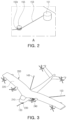
- FIG. 3 illustrates a structure in which the transfer portion 120 of the vertiport system 100 is connected to the aircraft 200 according to an example embodiment of the present disclosure.
- FIG. 4 illustrates a structure in which the front transfer unit 130 of the vertiport system 100 is connected to the aircraft 200 according to an example embodiment of the present disclosure.
- FIG. 5 illustrates a structure in which the rear transfer units 140 and 150 of the vertiport system 100 are connected to the aircraft 200 according to an example embodiment of the present disclosure.
- FIGS. 3 to 5 illustrate a structure in which the transfer units 130, 140, and 150 of the transfer portion 120, illustrated in FIG. 1 , are connected to the aircraft 200.
- FIGS. 3 to 5 will be described with reference to FIG. 1 .
- FIG. 5 illustrates a connection structure between the second rear transfer unit 150 and the aircraft 200, and the connection structure may be substantially the same as a connection structure between the first rear transfer unit 140 and the aircraft 200.
- the vertiport system 100 may include the transfer portion 120 for transfer of the aircraft 200, and the transfer portion 120 may be connected to each of a plurality of landing gear members 230 and 240 of the aircraft 200 to tow and transfer the aircraft 200.
- the aircraft 200 may be an air mobility vehicle capable of vertical takeoff and landing and may include an airframe (or a fuselage) 210 in which passengers board and/or cargo is loaded, a wing portion 220 coupled to an upper portion of the airframe 210, the wing portion 220 including a rotor generating a lifting force, and the plurality of landing gear members 230 and 240 coupled to a lower portion of the airframe 210, the plurality of landing gear members 230 and 240 supporting takeoff, landing, and taxiing of the aircraft 200.
- the plurality of landing gear members 230 and 240 may include a nose landing gear member 230 positioned at the front and two main landing gear members 240 positioned at the rear.
- the transfer portion 120 may include the front transfer unit 130 connected to the nose landing gear member 230 of the aircraft 200 and two rear transfer units (for example, the first rear transfer unit 140 and the second rear transfer unit 150) connected to the two main landing gear members 240 of the aircraft 200.
- the front transfer unit 130 may include the front cable 133 detachably connected to the nose landing gear member 230.
- the first rear transfer unit 140 and the second rear transfer unit 150 may include the first rear cable 143 and the second rear cable 153 detachably connected to the main landing gear members 240, respectively.
- the front cable 133 of the front transfer unit 130 may be connected to the nose landing gear member 230 of the aircraft 200.
- the front transfer unit 130 may be connected to the nose landing gear member 230 in a form in which a wheel 231 of the nose landing gear member 230 is rotatable, when the aircraft 200 is transferred/towed.
- the front cable 133 may include a first hook 133h connected to a wheel cap 232 of the nose landing gear member 230.
- the first hook 133h may be coupled to one end of the front cable 133, and the first hook 133h may be detachably connected to the wheel cap 232 of the nose landing gear member 230.
- the first hook 133h may be fastened to the wheel cap 232.
- the first hook 133h may be separated from the wheel cap 232.
- a connection structure between the front cable 133 and the nose landing gear member 230 is not limited to the form illustrated in FIG. 4 , and the front cable 133 may be detachable and may be connected in various manners within a structure in which the wheel 231 of the nose landing gear member 230 is rotatable, when the aircraft 200 is transferred.
- the second rear cable 153 of the second rear transfer unit 150 may be connected to the main landing gear member 240 of the aircraft 200.
- the second rear transfer unit 150 may be connected to the main landing gear member 240 in a form in which a wheel 241 of the main landing gear member 240 is rotatable, when the aircraft 200 is transferred/towed.
- the second rear cable 153 may include a second hook 153h connected to a support bar 242 supporting the wheel 241 of the main landing gear member 240, and the support bar 242 may include a fastener 243 to which the second hook 153h is fastened.
- the second hook 153h may be coupled to one end of the second rear cable 153, and the second hook 153h may be detachably connected to the fastener 243 of the main landing gear member 240.
- the second hook 153h may be fastened to the fastener 243.
- the second hook 153h may be separated from the fastener 243.
- a connection structure between the second rear cable 153 and the main landing gear member 240 is not limited to the form illustrated in FIG. 5 , and the second rear cable 153 may be detachable and may be connected in various manners within a structure in which the wheel 241 of the main landing gear member 240 is rotatable, when the aircraft 200 is transferred.
- connection structure between the rear transfer units 140 and 150 and the main landing gear member 240 has been described based on the second rear transfer unit 150, and it may be applied to the first rear transfer unit 140 in the same manner.
- the aircraft 200 may include a tricycle landing gear member including one nose landing gear member 230 and two main landing gear members 240.
- types and shapes of the landing gear members 230 and 240 provided in the aircraft 200 are not limited to the illustrated example embodiment.
- a structure in which the front cable 133 and the rear cables 143 and 153 are connected to the aircraft 200 may be appropriately modified depending on the types and shapes of the landing gear members 230 and 240.
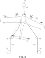
- FIG. 6 illustrates an operation of controlling, by the vertiport system 100, a motor of the transfer portion 120 according to an example embodiment of the present disclosure.
- a vertiport system (for example, the vertiport system 100 in FIG. 1 ) may control the front motor 131, the first rear motor 141, and the second rear motor 151, included in a transfer portion (for example, the transfer portion 120 in FIG. 1 ), thereby stably transferring the aircraft 200.
- a motor controller (for example, the motor controller 161 in FIG. 1 ) of the vertiport system 100 may collaboratively control the front motor 131, the first rear motor 141, and the second rear motor 151 to generate a tension force and/or a traction force in the front cable 133, the first rear cable 143, and the second rear cable 153 for moving the aircraft 200 in a rectilinear direction.
- the rectilinear direction may be parallel to a direction in which a takeoff and landing area 111 and a transfer area 113 oppose each other.
- the rectilinear direction may refer to a direction parallel to an imaginary straight line connecting a center of the takeoff and landing area 111 and a center of the transfer area 113 to each other.
- a moving distance of the aircraft 200 may be a shortest distance.
- a plurality of motors 131, 141, and 151, included in the transfer portion 120, may measure tension forces of the cables 133, 143, and 153 respectively connected thereto and may transmit measured data to the motor controller 161.
- the plurality of motors 131, 141, and 151 may include a sensor (not illustrated) capable of measuring tension forces generated in the cables 133, 143, and 153 and a communication module (not illustrated) capable of transmitting measured tension force data to the motor controller 161.
- FIG. 6 illustrates motor housings forming the exteriors of the front motor 131, the first rear motor 141, and the second rear motor 151.
- rollers around which cables 133, 143, and 153 are wound, sensors, and communication modules may be disposed in the motor housings, respectively.
- the motor controller 161 may control, based on the tension force data transmitted from the front motor 131, the first rear motor 141, and the second rear motor 151, driving of the front motor 131, the first rear motor 141, and the second rear motor 151.
- the motor controller 161 may control the front motor 131, the first rear motor 141, and the second rear motor 151 using the tension force data transmitted from the motors 131, 141, and 151, such that the front cable 133, the first rear cable 143, and the second rear cable 153 may move the aircraft 200 in the rectilinear direction.
- the motor controller 161 may detect, based on the tension force data, a cable having a tension force value greater or less than a reference tension force value, among the front cable 133, the first rear cable 143, and the second rear cable 153, may detect a cable having abnormal behavior, or may control a corresponding motor to set a tension force value of a corresponding cable to the reference tension force value.
- the motor controller 161 may control the second rear motor 151 such that a tension force of the first rear cable 143 increases (for example, see the second rear cable 153 indicated by a dotted line in FIG. 6 ), thereby stably maintaining the tension forces of the front cable 133, the first rear cable 143, and the second rear cable 153 applied to the aircraft 200.
- a direction in which the aircraft 200 is turned in FIG. 6 may be exemplary, and the aircraft 200 may be turned to be oriented in a direction other than the rectilinear direction due to the overall effect of the tension forces applied to the front cable 133, the first rear cable 143, and the second rear cable 153.
- the vertiport system 100 may measure or detect, in real time, tension forces of the plurality of motors 131, 141, and 151 applied to the plurality of cables 133, 143, and 153, and may collaboratively control, based on the measured tension forces, the plurality of motors 131, 141, and 151, thereby stably maintaining a tension force and/or a traction force applied to the aircraft 200 by the plurality of cables 133, 143, and 153, and allowing the aircraft 200 to move forward and backward in the rectilinear direction.
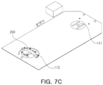
- FIGS. 7A, 7B , and 7C illustrate an operation in which the aircraft 200 is transferred in the vertiport system 100 according to an example embodiment of the present disclosure.
- FIGS. 7A, 7B , and 7C illustrate an operation in which the aircraft 200 lands in the takeoff and landing area 111 and then is transferred to the transfer area 113 by the transfer portion 120.
- FIGS. 7A, 7B , and 7C will be described with reference to FIGS. 1 to 6 .
- the aircraft 200 lands in the takeoff and landing area 111 under the control of the control center 170.
- the front cable 133, the first rear cable 143, and the second rear cable 153 may be connected to a landing gear member of the aircraft 200.
- an operation of fastening the cables 133, 143, and 153 to the landing gear members may be performed by a ground crew member or a worker.
- the aircraft 200 When the aircraft 200 lands in the takeoff and landing area 111, the aircraft 200 may land such that a front surface thereof opposes the front motor 131 or the transfer area 113. In various example embodiments, when the takeoff and landing area 111 is rotatable, the aircraft 200 may land in the takeoff and landing area 111, and then the front surface of the aircraft 200 may rotate such that the front surface of the aircraft 200 opposes the transfer area 113.
- the front cable 133, the first rear cable 143, and the second rear cable 153 may be fastened to the landing gear members of the aircraft 200, and then the front motor 131, the first rear motor 141, and the second rear motor 151 may be driven to transfer the aircraft 200.
- the front motor 131, the first rear motor 141, and the second rear motor 151 may be driven to generate a tension force and/or a traction force for transfer of the aircraft 200 in each of the front cable 133, the first rear cable 143, and the second rear cable 153.
- the front cable 133 When the aircraft 200 is transferred from the takeoff and landing area 111 to the transfer area 113, the front cable 133 may be wound around the front motor 131, and accordingly a length of the front cable 133, positioned between the aircraft 200 and the front motor 131, may decrease.
- the rear cables 143 and 153 may be unwound from the rear motors 141 and 151, and accordingly lengths of the rear cables 143 and 153, positioned between the aircraft 200 and the rear motors 141 and 151, may increase.
- the front cable 133, the first rear cable 143, and the second rear cable 153 may be separated and disconnected from the landing gear member of the aircraft 200.
- an operation of connecting/disconnecting the cables 133, 143, and 153 and the landing gear members to/from each other may be performed by a ground crew member or a worker.
- a direction in which the aircraft 200 is oriented may be adjusted by rotating the transfer area 113, as necessary.
- a front surface of the aircraft 200 immediately after being transferred to the transfer area 113 may be in a state of opposing the front motor 131, and the transfer area 113 may be rotated, such that the front surface of the aircraft 200 may oppose the takeoff and landing area 111 or the rear motors 141 and 151.
- An operation of transferring the aircraft 200, positioned in the transfer area 113, to the takeoff and landing area 111 may be performed in the order of FIGS. 7C , 7B, and 7A .
- the aircraft 200 may be disposed such that the front surface thereof opposes the front motor 131, and then the cables 133, 143, and 153 may be connected to the landing gear members.
- the aircraft 200 may be aligned in a direction in which the front cable 133 is connectable to the nose landing gear member 230 and the rear cables 143 and 153 are connectable to the main landing gear members 240 through rotation of the transfer area 113.
- the transfer area 113 may be rotated such that the front surface of the aircraft 200 is disposed to oppose the front motor 131, and then the front cable 133, the first rear cable 143, and the second rear cable 153 may be connected to the aircraft 200.
- the aircraft 200 when the aircraft 200 temporarily stops on the port body 110 (in particular, the takeoff and landing area 111 and the transfer area 113) and is moved to the takeoff and landing area 111 and the transfer area 113, the aircraft 200 may be connected through the plurality of cables 133, 143, and 153 having a predetermined degree of tension force, and thus may be stably fixed.
- a vertiport may be installed or provided on a roof of a building.
- the aircraft 200 may be prevented or minimized to be overturned or greatly shaken by strong winds generated by the vertiport, when the aircraft 200 is moved and/or parked.
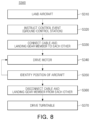
- FIG. 8 illustrates a method S300 of controlling the vertiport system 100 according to an example embodiment of the present disclosure.
- FIG. 8 is a flowchart illustrating the method S300 of controlling the vertiport system 100 described above with reference to FIGS. 1 to 6 . Some operations of FIG. 8 may be performed by at least some components of the vertiport system 100 illustrated in FIGS. 1 to 6 .
- FIG. 8 will be described with reference to FIGS. 1 to 6 , and a repeated description will be omitted.
- the control method S300 of the vertiport system 100 may include an operation in which an aircraft lands (S310), an operation of instructing a control event (S320), an operation of connecting a cable and a landing gear member to each other (S330), an operation of driving a motor (S340), an operation of identifying a position of the aircraft (S350), an operation of disconnecting the cable and the landing gear member from each other (S360), and an operation of driving a turntable (S370).
- the aircraft 200 may land in the takeoff and landing area 111.
- the control center 170 may comprehensively consider an environment within a control area and may transmit control information and an instruction for transfer of the aircraft 200 to the controller 160 and a ground crew member.
- a ground crew member may connect the front cable 133 to the nose landing gear member 230 and may connect the first rear cable 143 and the second rear cable 153 to two main landing gear members 240.
- the aircraft 200 may be transferred by driving a motor through the motor controller 161.
- the motor controller 161 may collaboratively control the front motor 131, the first rear motor 141, and the second rear motor 151, thereby moving the aircraft 200 in a rectilinear direction.
- the position of the aircraft 200 may be identified and whether transfer of the aircraft 200 to the transfer area 113 has been completed may be identified. As a result of identifying the position of the aircraft 200, when additional transfer to the transfer area 113 is necessary, the motor may continue to be driven. When transfer to the transfer area 113 is completed, driving of the motor may be stopped.
- the ground crew member may disconnect the front cable 133 from the nose landing gear member 230 and may disconnect the first rear cable 143 and the second rear cable 153 from the two main landing gear members 240.
- a direction of the aircraft 200 may be adjusted by rotating the transfer area 113 in which the aircraft 200 is positioned.
Landscapes
- Engineering & Computer Science (AREA)
- Mechanical Engineering (AREA)
- Aviation & Aerospace Engineering (AREA)
- Transmission Devices (AREA)
- Control Of Position, Course, Altitude, Or Attitude Of Moving Bodies (AREA)
Abstract
Description
- This application claims the benefit of
Korean Patent Application No. 10-2023-0167964, filed on November 28, 2023 - The present disclosure relates to a vertiport system including a transfer apparatus using a cable.
- Recently, urban air mobility (UAM) vehicles for future transportation and traffic systems have been developed. A UAM vehicle may be an aircraft capable of vertical takeoff and landing flight. The development of a vertiport, a UAM vehicle takeoff/landing site, has been required along with the development of a UAM vehicle.
- A vertiport may include infrastructure or systems with support services and equipment for landing, ground handling, and takeoff of manned or unmanned vertical takeoff and landing (VTOL) aircrafts. The vertiport may be generally considered to be installed on the rooftops of high-rise buildings or in large parks. The vertiport may have a smaller footprint with smaller landing and takeoff regions, as compared to a typical airport with general runways.
- UAM vehicles may require taxiing for various purposes such as passenger boarding and disembarking/charging/parking/hangar transfer within a vertiport.
- Embodiments of the present disclosure provide a vertiport system capable of rapidly and stably transferring an aircraft along a predetermined transfer path within a vertiport and stably fixing the aircraft during transfer and parking of the aircraft.
- According to an embodiment of the present disclosure, there is provided a vertiport system including a first area, a second area provided in a position different from that of the first area, and a transfer portion configured to transfer an aircraft between the first area and the second area. The transfer portion may include a front transfer unit having a front cable detachably connected to a front portion of the aircraft and a rear transfer unit having a rear cable detachably connected to a rear portion of the aircraft.
- The front cable may be configured to be detachably connected to a nose landing gear member of the aircraft. The rear cable may be configured to be detachably connected to a main landing gear member of the aircraft.
- The rear transfer unit may include a first rear transfer unit and a second rear transfer unit respectively connected to two main landing gear members provided in the aircraft. The rear cable may include a first rear cable provided in the first rear transfer unit and a second rear cable provided in the second rear transfer unit.
- The front transfer unit may further include a front motor to which the front cable is connected, the front motor being configured to provide a predetermined degree of tension force to the front cable.
- The first rear transfer unit may further include a first rear motor to which the first rear cable is connected, the first rear motor being configured to provide a predetermined degree of tension force to the first rear cable. The second rear transfer unit may further include a second rear motor to which the second rear cable is connected, the second rear motor being configured to provide a predetermined degree of tension force to the second rear cable.
- The transfer portion may be configured to generate a predetermined degree of tension force or traction force in at least one of the front cable, the first rear cable, and the second rear cable by driving the front motor, the first rear motor, and the second rear motor in a state in which the front cable, the first rear cable, and the second rear cable are connected to the aircraft.
- The front transfer unit may be disposed in the first area. The first rear transfer unit and the second rear transfer unit may be disposed in the second area.
- The aircraft may be transferred between the first area and the second area by driving the front motor, the first rear motor, and the second rear motor in a state in which the front cable, the first rear cable, and the second rear cable are connected thereto.
- The vertiport system may further include a motor controller configured to control the front motor, the first rear motor, and the second rear motor. The motor controller may be set to move the aircraft in a rectilinear direction by collaboratively controlling the front motor, the first rear motor, and the second rear motor.
- The motor controller may be set to detect tension force information of the front cable, the first rear cable, and the second rear cable, and to control, based on the detected tension force information, the front motor, the first rear motor, and the second rear motor.
- Each of the front motor, the first rear motor, and the second rear motor may include a sensor configured to measure the tension force information and a communication module configured to transmit the tension force information to the motor controller.
- The rectilinear direction may be a direction parallel to an imaginary straight line connecting a center of the first area and a center of the second area to each other.
- The first area may be a transfer area configured to transfer the aircraft to another area or a facility. The second area may be a takeoff and landing area provided for takeoff and landing of the aircraft.
- At least one of the first area and the second area may be configured to be rotatable.
- The vertiport system may further include a control center configured to control takeoff, landing, stopping, or transfer of the aircraft and to provide control information.
- According to another embodiment of the present disclosure, there is provided a method of transferring an aircraft in a vertiport system, the method including landing, by an aircraft, in a takeoff and landing area, connecting a front cable and a rear cable to a landing gear member of the aircraft, transferring the aircraft to a transfer area by driving a front motor to which the front cable is connected and a rear motor to which the rear cable is connected, and disconnecting the front cable and the rear cable from the landing gear member.
- The front cable may be connected to a nose landing gear member of the aircraft. The rear cable may include a first rear cable and a second rear cable connected to two main landing gear members of the aircraft. The rear motor may include a first rear motor corresponding to the first rear cable and a second rear motor corresponding to the second rear cable.
- In the transferring the aircraft by driving the motor, a predetermined degree of tension force or traction force may be formed in at least one of the front cable, the first rear cable, and the second rear cable by driving the front motor, the first rear motor, and the second rear motor.
- In the transferring the aircraft by driving the motor, the aircraft may be moved in a rectilinear direction by collaboratively controlling the front motor, the first rear motor, and the second rear motor.
- The transferring the aircraft by driving the motor may include detecting tension force information of the front cable, the first rear cable, and the second rear cable and controlling, based on the detected tension force information, the front motor, the first rear motor, and the second rear motor.
- According to an example embodiment of the present disclosure, an aircraft may be stably transferred and fixed within a vertiport by connecting a cable to a landing gear member of the aircraft, thereby preventing the aircraft from being greatly shaken or overturned by strong winds during transfer and parking of the aircraft.
- In addition, according to an example embodiment of the present disclosure, equipment such as a tug car may not be used for transfer of an aircraft, thereby reducing air pollution and noise pollution, and stably and efficiently performing a transfer.
- The above and other aspects, features, and advantages of embodiments of the present disclosure will be more clearly understood from the following detailed description, taken in conjunction with the accompanying drawings, in which:
-
FIG. 1 illustrates a vertiport system according to an example embodiment of the present disclosure; -
FIG. 2 illustrates a rear transfer unit of a vertiport system according to an example embodiment of the present disclosure; -
FIG. 3 illustrates a structure in which a transfer portion of a vertiport system is connected to an aircraft according to an example embodiment of the present disclosure; -
FIG. 4 illustrates a structure in which a front transfer unit of a vertiport system is connected to an aircraft according to an example embodiment of the present disclosure; -
FIG. 5 illustrates a structure in which a rear transfer unit of a vertiport system is connected to an aircraft according to an example embodiment of the present disclosure; -
FIG. 6 illustrates an operation of controlling, by a vertiport system, a motor of a transfer portion according to an example embodiment of the present disclosure; -
FIGS. 7A, 7B , and7C illustrate an operation in which an aircraft is transferred in a vertiport system according to an example embodiment of the present disclosure; and -
FIG. 8 illustrates a method of controlling a vertiport system according to an example embodiment of the present disclosure. - Various modifications may be made to the example embodiments. Here, the example embodiments are not construed as being limited to the disclosure and should be understood to include all changes, equivalents, and replacements within the idea and the technical scope of the disclosure.
- Terms such as first, second, A, B, (a), (b), and the like may be used herein to describe components. Each of these terminologies is not used to define an essence, order, or sequence of a corresponding component but is used merely to distinguish the corresponding component from other component(s). For example, a first component may be referred to as a second component, and similarly the second component may also be referred to as the first component. The term "and/or" may include combinations of a plurality of related described items or any of a plurality of related described items.
- The terminology used herein is for the purpose of describing particular example embodiments only and is not to be limiting of the example embodiments. As used herein, the singular forms "a," "an," and "the" are intended to include the plural forms as well, unless the context clearly indicates otherwise. As used herein, the term "and/or" includes any one and any combination of any two or more of the associated listed items. It will be further understood that the terms "comprises" and/or "comprising," when used in this code, specify the presence of stated features, integers, steps, operations, elements, components, or a combination thereof, but these terms do not preclude the presence or addition of one or more other features, integers, steps, operations, elements, components, and/or groups thereof.
- Unless otherwise defined herein, all terms used herein including technical or scientific terms have the same meanings as those generally understood by one of ordinary skill in the art. Terms defined in generally used dictionaries should be construed to have meanings matching contextual meanings in the related art and are not to be construed as having an ideal or excessively formal meaning, unless otherwise defined herein.
- An aircraft may refer to a mobility vehicle capable of moving by flying in the sky. That is, the aircraft, in addition to referring to a helicopter, drone, tilt rotor, fixed-wing airplane, and the like, may include vehicles capable of flying in a state in which the vehicles move on the ground using wheels, and the wheels are separated from the ground. In addition, the aircraft may include a manned aircraft and an unmanned aircraft. The manned aircraft may include an airframe capable of operating autonomously in addition to an airframe controlled by a pilot.
- Hereinafter, example embodiments of the present disclosure will be described with reference to the accompanying drawings.
-
FIG. 1 illustrates avertiport system 100 according to an example embodiment of the present disclosure.FIG. 2 illustratesrear transfer units vertiport system 100 according to an example embodiment of the present disclosure. -
FIG. 1 is a schematic diagram illustrating thevertiport system 100 according to an example embodiment.FIG. 2 is an enlarged view of portion A illustrated inFIG. 1 . - The
vertiport system 100 according to an example embodiment, a takeoff and landing site (for example, a vertical takeoff and landing airfield or station) for anaircraft 200 capable of vertical takeoff and landing (VTOL) may include infrastructure for accommodating an aircraft from a flight, resetting the aircraft for a subsequent flight, and allowing the aircraft to depart for a subsequent flight. Here, theaircraft 200 may be an air mobility vehicle including an urban air mobility (UAM) vehicle and an advanced air mobility (AAM) vehicle, and a type of theaircraft 200 is not particularly limited. - The
vertiport system 100 may refer to various facilities providing space for vertical takeoff and landing of an aircraft, and thevertiport system 100 may be understood as including a verti-hub, a verti-port, or a verti-stop categorized depending on a size thereof. For example, the verti-hub may be a largest UAM airfield, may allow large-scale transfer of surrounding traffic such as airports, may have support infrastructure such as charging and maintenance, and may allow a large number of UAM airframes to be parked after the end of operation. The vertiport may be a vertical takeoff and landing airfield smaller than that of the verti-hub, may have airframe support infrastructure (charging and maintenance), and may provide passenger convenience facilities. The verti-stop may be smaller than the verti-port and may be a small takeoff and landing airfield having one or two parking ramps. - Referring to
FIGS. 1 and2 , thevertiport system 100 according to an example embodiment may include aport body 110, a transfer portion 120, acontroller 160, and acontrol center 170. - The
port body 110 may be configured to allow theaircraft 200 to take off or land, stop, or move. For example, theport body 110 may include components for takeoff, landing, stopping, and movement of theaircraft 200. - The
port body 110 may include a takeoff andlanding area 111 in which theaircraft 200 takes off or lands and atransfer area 113 for stopping theaircraft 200 or moving theaircraft 200 to another area of the port body 110 (or the vertiport system 100). Each of the takeoff andlanding area 111 and thetransfer area 113 may be configured as one or more areas. The takeoff andlanding area 111 and thetransfer area 113 may be examples of separate areas provided for theaircraft 200 to be transferred, to be positioned, or to stop, and they may also be referred to as a first area and a second area in various example embodiments. - The takeoff and
landing area 111 may be provided in a portion of theport body 110, and thetransfer area 113 may be provided in another portion of theport body 110 spaced apart from the takeoff andlanding area 111. For example, theport body 110 may be formed such that the takeoff andlanding area 111 is disposed on one side of abasic area 115, and thetransfer area 113 is disposed on the other side of thebasic area 115. - The
aircraft 200 may vertically take off or land in the takeoff andlanding area 111. Theaircraft 200, landing in the takeoff andlanding area 111, may be transferred to thetransfer area 113 through the transfer portion 120. In addition, theaircraft 200 positioned in thetransfer area 113 may be transferred to the takeoff andlanding area 111 through the transfer portion 120. - The takeoff and
landing area 111 and thetransfer area 113 may be provided in the form of a circular platform installed in the port body 110 (or the basic area 115). In various example embodiments, at least one of the takeoff andlanding area 111 and thetransfer area 113 may be rotatable with respect to theport body 110. The circular platforms of the takeoff andlanding area 111 and/or thetransfer area 113 may be configured to physically rotate. For example, at least one of the takeoff andlanding area 111 and thetransfer area 113 may include a motor for rotating a circular platform, and the circular platform may be coupled to the motor to be rotated by the motor. - The
transfer area 113 may be rotatable with respect to theport body 110. For example, the transfer area 113 (that is, the circular platform of the transfer area 113) may rotate with respect to thebasic area 115 and the takeoff andlanding area 111 of theport body 110. Theaircraft 200, stopping in thetransfer area 113, may rotate with thetransfer area 113 as thetransfer area 113 rotates, and a direction in which theaircraft 200 is oriented may be adjusted based on the rotation of thetransfer area 113. - The
transfer area 113 may be an area in which theaircraft 200, transferred from the takeoff andlanding area 111, temporarily stops before being transferred to another area, or an area in which theaircraft 200, transferred from another area, temporarily stops before being transferred to the takeoff andlanding area 111. In addition, as another example, thetransfer area 113 may be an area in which theaircraft 200 temporarily stops for boarding and disembarkation of passengers and/or loaded cargo, but the present disclosure is not limited thereto. - Although not illustrated, the
transfer area 113 may be configured to transfer theaircraft 200 to a maintenance area, a charging area, a boarding and disembarking area, a transit area, and a containment area provided in the vertiport system 100 (or a smart building including the vertiport system 100). For example,FIG. 1 may be understood as a schematic diagram illustrating a rooftop of a building including thevertiport system 100, and the transfer area 113 (that is, the circular platform of the transfer area 113) may be configured to ascend and descend within a building. - The transfer portion 120 may transfer/move the
aircraft 200. For example, the transfer portion 120 may transfer theaircraft 200 between the takeoff andlanding area 111 and thetransfer area 113 by towing theaircraft 200 using a cable. The takeoff andlanding area 111 and thetransfer area 113 may be exemplary, and the transfer portion 120 is not necessarily limited to transferring theaircraft 200 between the takeoff andlanding area 111 and thetransfer area 113, and the transfer portion 120 may be configured to transfer theaircraft 200 between the first area and the second area, spaced apart from each other and separated from each other. - The transfer portion 120 may include a
front transfer unit 130 disposed in thetransfer area 113 and connected to a front surface or a front portion of theaircraft 200 andrear transfer units landing area 111 and connected to a rear surface or a rear portion of theaircraft 200. - The
front transfer unit 130 may be connected to a nose landing gear member (for example, a noselanding gear member 230 inFIG. 3 ) of theaircraft 200 to transfer theaircraft 200. Therear transfer units landing gear member 240 inFIG. 3 ) to transfer theaircraft 200. - The
front transfer unit 130 and therear transfer units cables aircraft 200 and may provide a tension force and/or a traction force to thecables motors front transfer unit 130 and therear transfer units - The
rear transfer units rear transfer unit 140 and a secondrear transfer unit 150. For example, theaircraft 200 may include two main landing gear members, and therear transfer units rear transfer unit 140 may be connected to a first main landing gear member, and the secondrear transfer unit 150 may be connected to a second main landing gear member. - The
front transfer unit 130 may include afront motor 131 and afront cable 133. Thefront cable 133 may be connected to thefront motor 131, and thefront motor 131 may provide a tension force and/or a traction force to thefront cable 133. Thefront transfer unit 130 may have a structure in which at least a portion of thefront cable 133 is accommodated in thefront motor 131 in a state of being wound such that thefront cable 133 is unwound from or wound around thefront motor 131 by driving thefront motor 131. For example, thefront cable 133 may be wound around at least a portion of thefront motor 131 by rotating thefront motor 131 in a direction or may be unwound from thefront motor 131 by rotating thefront motor 131 in an opposite direction in a state in which both ends of thefront cable 133 are connected to thefront motor 131 and theaircraft 200. A traction force and a tension force for transfer of theaircraft 200 may be formed in thefront cable 133 based on an operation of winding or unwinding at least a portion of thefront cable 133 by controlling thefront motor 131. - The first
rear transfer unit 140 may include a firstrear motor 141, a firstrear cable 143, and afirst guide member 145, and the secondrear transfer unit 150 may include a secondrear motor 151, a secondrear cable 153, and asecond guide member 155. For example, the firstrear transfer unit 140 and the secondrear transfer unit 150 may be different from each other in terms of a position and a portion connected to theaircraft 200 and may have the same shape and structure. - The
rear cables rear motors rear motors rear cables rear transfer units rear cables rear motors rear cables rear motors rear motors rear cables rear motors rear motors rear motors rear motors rear cables rear motors aircraft 200. A traction force and a tension force for transfer of theaircraft 200 may be formed in therear cables rear cables rear motors - The
guide members rear cables aircraft 200 and therear motors rear cables guide members rear motors guide members aircraft 200. - The
guide members rear cables rear cables aircraft 200 and theguide members rear cables rear motors guide members -
Recesses 155r in which therear cables guide members rear cables rear motors rear cables recesses 155r of theguide members - The
front transfer unit 130 and therear transfer units aircraft 200. - First, when the
aircraft 200 is transferred from the takeoff andlanding area 111 to thetransfer area 113, thefront transfer unit 130 may operate to form a traction force for towing theaircraft 200 as thefront cable 133 is wound by thefront motor 131, and therear transfer units rear cables rear motors front cable 133. - Conversely, when the
aircraft 200 is transferred from thetransfer area 113 to the takeoff andlanding area 111, therear transfer units aircraft 200 as therear cables rear motors front transfer unit 130 may operate to maintain an appropriate tension force while thefront cable 133 is unwound by thefront motor 131, thereby supporting the traction of therear cables - A connection structure between the transfer portion 120 and the
aircraft 200 will be described in more detail below with reference toFIGS. 3 to 5 . - The
controller 160 may control an operation of at least a portion of thevertiport system 100. Thecontroller 160 may include amotor controller 161 controlling themotors platform controller 162 controlling rotation of thetransfer area 113. - The
motor controller 161 may independently and/or dependently control operations of thefront motor 131 of thefront transfer unit 130, the firstrear motor 141 of the firstrear transfer unit 140, and the secondrear motor 151 of the secondrear transfer unit 150. Themotor controller 161 may be set to collaboratively control (or cooperatively control) thefront motor 131, the firstrear motor 141, and the secondrear motor 151, such that theaircraft 200 may move forward and backward in a rectilinear direction when theaircraft 200 is transferred. - The
platform controller 162 may control a rotational operation of a platform of thetransfer area 113. However, the present disclosure is not limited to rotation control of thetransfer area 113. In various example embodiments, when the takeoff andlanding area 111 is rotatably provided, theplatform controller 162 may also be configured to control a rotational operation of a platform of the takeoff andlanding area 111. - The
control center 170 may comprehensively manage and monitor thevertiport system 100 and may control takeoff, landing, stopping, and transfer of theaircraft 200. Thecontrol center 170 may be positioned to be adj acent to the takeoff andlanding area 111 and may comprehensively consider an operating environment within a control area, thereby providing control information on takeoff, landing, and transfer of theaircraft 200 to thecontroller 160 and/or a ground crew member. -
FIG. 1 schematically illustrates thevertiport system 100 according to an example embodiment. Components of thevertiport system 100 are not limited to those in the illustrated example embodiment, and other components (for example, a takeoff and landing guide unit, a walking area, and the like) may be further included in various example embodiments. - In addition, according to the example embodiment illustrated in
FIG. 1 , thevertiport system 100 may include one takeoff andlanding area 111 and onetransfer area 113, but the present disclosure is not limited thereto. In various example embodiments, at least one of the takeoff andlanding area 111 and thetransfer area 113 may be configured as two or more areas. For example, thevertiport system 100 may include one takeoff andlanding area 111 and a plurality oftransfer areas 113, and afront transfer unit 130 may be provided in each of the plurality oftransfer areas 113. In this case, theaircraft 200, positioned in the takeoff andlanding area 111, may be transferred using afront transfer unit 130 of atransfer area 113 to be transferred, among the plurality oftransfer areas 113, andrear transfer units landing area 111. -
FIG. 3 illustrates a structure in which the transfer portion 120 of thevertiport system 100 is connected to theaircraft 200 according to an example embodiment of the present disclosure.FIG. 4 illustrates a structure in which thefront transfer unit 130 of thevertiport system 100 is connected to theaircraft 200 according to an example embodiment of the present disclosure.FIG. 5 illustrates a structure in which therear transfer units vertiport system 100 are connected to theaircraft 200 according to an example embodiment of the present disclosure. -
FIGS. 3 to 5 illustrate a structure in which thetransfer units FIG. 1 , are connected to theaircraft 200. Hereinafter,FIGS. 3 to 5 will be described with reference toFIG. 1 . -
FIG. 5 illustrates a connection structure between the secondrear transfer unit 150 and theaircraft 200, and the connection structure may be substantially the same as a connection structure between the firstrear transfer unit 140 and theaircraft 200. - Referring to
FIGS. 3 to 5 together withFIG. 1 , thevertiport system 100 according to an example embodiment may include the transfer portion 120 for transfer of theaircraft 200, and the transfer portion 120 may be connected to each of a plurality oflanding gear members aircraft 200 to tow and transfer theaircraft 200. - The
aircraft 200 may be an air mobility vehicle capable of vertical takeoff and landing and may include an airframe (or a fuselage) 210 in which passengers board and/or cargo is loaded, awing portion 220 coupled to an upper portion of theairframe 210, thewing portion 220 including a rotor generating a lifting force, and the plurality oflanding gear members airframe 210, the plurality oflanding gear members aircraft 200. The plurality oflanding gear members landing gear member 230 positioned at the front and two mainlanding gear members 240 positioned at the rear. - The transfer portion 120 may include the
front transfer unit 130 connected to the noselanding gear member 230 of theaircraft 200 and two rear transfer units (for example, the firstrear transfer unit 140 and the second rear transfer unit 150) connected to the two mainlanding gear members 240 of theaircraft 200. - The
front transfer unit 130 may include thefront cable 133 detachably connected to the noselanding gear member 230. The firstrear transfer unit 140 and the secondrear transfer unit 150 may include the firstrear cable 143 and the secondrear cable 153 detachably connected to the mainlanding gear members 240, respectively. - As illustrated in
FIG. 4 , thefront cable 133 of thefront transfer unit 130 may be connected to the noselanding gear member 230 of theaircraft 200. Thefront transfer unit 130 may be connected to the noselanding gear member 230 in a form in which awheel 231 of the noselanding gear member 230 is rotatable, when theaircraft 200 is transferred/towed. Thefront cable 133 may include afirst hook 133h connected to awheel cap 232 of the noselanding gear member 230. For example, thefirst hook 133h may be coupled to one end of thefront cable 133, and thefirst hook 133h may be detachably connected to thewheel cap 232 of the noselanding gear member 230. When theaircraft 200 is transferred, thefirst hook 133h may be fastened to thewheel cap 232. When transfer of theaircraft 200 is completed, thefirst hook 133h may be separated from thewheel cap 232. - A connection structure between the
front cable 133 and the noselanding gear member 230 is not limited to the form illustrated inFIG. 4 , and thefront cable 133 may be detachable and may be connected in various manners within a structure in which thewheel 231 of the noselanding gear member 230 is rotatable, when theaircraft 200 is transferred. - As illustrated in
FIG. 5 , the secondrear cable 153 of the secondrear transfer unit 150 may be connected to the mainlanding gear member 240 of theaircraft 200. The secondrear transfer unit 150 may be connected to the mainlanding gear member 240 in a form in which awheel 241 of the mainlanding gear member 240 is rotatable, when theaircraft 200 is transferred/towed. The secondrear cable 153 may include asecond hook 153h connected to a support bar 242 supporting thewheel 241 of the mainlanding gear member 240, and the support bar 242 may include afastener 243 to which thesecond hook 153h is fastened. For example, thesecond hook 153h may be coupled to one end of the secondrear cable 153, and thesecond hook 153h may be detachably connected to thefastener 243 of the mainlanding gear member 240. When theaircraft 200 is transferred, thesecond hook 153h may be fastened to thefastener 243. When transfer of theaircraft 200 is completed, thesecond hook 153h may be separated from thefastener 243. - A connection structure between the second
rear cable 153 and the mainlanding gear member 240 is not limited to the form illustrated inFIG. 5 , and the secondrear cable 153 may be detachable and may be connected in various manners within a structure in which thewheel 241 of the mainlanding gear member 240 is rotatable, when theaircraft 200 is transferred. - In the above description, the connection structure between the
rear transfer units landing gear member 240 has been described based on the secondrear transfer unit 150, and it may be applied to the firstrear transfer unit 140 in the same manner. - According to the example embodiment illustrated in
FIGS. 3 to 5 , theaircraft 200 may include a tricycle landing gear member including one noselanding gear member 230 and two mainlanding gear members 240. However, types and shapes of thelanding gear members aircraft 200 are not limited to the illustrated example embodiment. In addition, a structure in which thefront cable 133 and therear cables aircraft 200 may be appropriately modified depending on the types and shapes of thelanding gear members -
FIG. 6 illustrates an operation of controlling, by thevertiport system 100, a motor of the transfer portion 120 according to an example embodiment of the present disclosure. - Referring to
FIG. 6 , a vertiport system (for example, thevertiport system 100 inFIG. 1 ) according to an example embodiment may control thefront motor 131, the firstrear motor 141, and the secondrear motor 151, included in a transfer portion (for example, the transfer portion 120 inFIG. 1 ), thereby stably transferring theaircraft 200. - A motor controller (for example, the
motor controller 161 inFIG. 1 ) of thevertiport system 100 may collaboratively control thefront motor 131, the firstrear motor 141, and the secondrear motor 151 to generate a tension force and/or a traction force in thefront cable 133, the firstrear cable 143, and the secondrear cable 153 for moving theaircraft 200 in a rectilinear direction. - Here, the rectilinear direction may be parallel to a direction in which a takeoff and
landing area 111 and atransfer area 113 oppose each other. For example, the rectilinear direction may refer to a direction parallel to an imaginary straight line connecting a center of the takeoff andlanding area 111 and a center of thetransfer area 113 to each other. When theaircraft 200 moves in the rectilinear direction, a moving distance of theaircraft 200 may be a shortest distance. - A plurality of
motors cables motor controller 161. The plurality ofmotors cables motor controller 161. For example, it may be understood thatFIG. 6 illustrates motor housings forming the exteriors of thefront motor 131, the firstrear motor 141, and the secondrear motor 151. Although not illustrated, rollers around whichcables - The
motor controller 161 may control, based on the tension force data transmitted from thefront motor 131, the firstrear motor 141, and the secondrear motor 151, driving of thefront motor 131, the firstrear motor 141, and the secondrear motor 151. For example, themotor controller 161 may control thefront motor 131, the firstrear motor 141, and the secondrear motor 151 using the tension force data transmitted from themotors front cable 133, the firstrear cable 143, and the secondrear cable 153 may move theaircraft 200 in the rectilinear direction. - The
motor controller 161 may detect, based on the tension force data, a cable having a tension force value greater or less than a reference tension force value, among thefront cable 133, the firstrear cable 143, and the secondrear cable 153, may detect a cable having abnormal behavior, or may control a corresponding motor to set a tension force value of a corresponding cable to the reference tension force value. - As illustrated in
FIG. 6 , when the secondrear cable 153 has an insufficient tension force (for example, see the secondrear cable 153 indicated by a solid line inFIG. 6 ), a phenomenon may occur in which theaircraft 200 is turned toward the firstrear cable 143 due to tension forces of thefront cable 133 and the firstrear cable 143. For example, based onFIG. 6 , when the secondrear cable 153 has an insufficient tension force, a front surface of theaircraft 200 may not oppose thefront motor 131, but may be turned toward a right side of thefront motor 131. In this case, themotor controller 161 may control the secondrear motor 151 such that a tension force of the firstrear cable 143 increases (for example, see the secondrear cable 153 indicated by a dotted line inFIG. 6 ), thereby stably maintaining the tension forces of thefront cable 133, the firstrear cable 143, and the secondrear cable 153 applied to theaircraft 200. - A direction in which the
aircraft 200 is turned inFIG. 6 may be exemplary, and theaircraft 200 may be turned to be oriented in a direction other than the rectilinear direction due to the overall effect of the tension forces applied to thefront cable 133, the firstrear cable 143, and the secondrear cable 153. - The
vertiport system 100 according to an example embodiment may measure or detect, in real time, tension forces of the plurality ofmotors cables motors aircraft 200 by the plurality ofcables aircraft 200 to move forward and backward in the rectilinear direction. -
FIGS. 7A, 7B , and7C illustrate an operation in which theaircraft 200 is transferred in thevertiport system 100 according to an example embodiment of the present disclosure. -
FIGS. 7A, 7B , and7C illustrate an operation in which theaircraft 200 lands in the takeoff andlanding area 111 and then is transferred to thetransfer area 113 by the transfer portion 120. Hereinafter,FIGS. 7A, 7B , and7C will be described with reference toFIGS. 1 to 6 . - Referring to
FIG. 7A , theaircraft 200 lands in the takeoff andlanding area 111 under the control of thecontrol center 170. After theaircraft 200 lands in the takeoff andlanding area 111, thefront cable 133, the firstrear cable 143, and the secondrear cable 153 may be connected to a landing gear member of theaircraft 200. For example, an operation of fastening thecables - When the
aircraft 200 lands in the takeoff andlanding area 111, theaircraft 200 may land such that a front surface thereof opposes thefront motor 131 or thetransfer area 113. In various example embodiments, when the takeoff andlanding area 111 is rotatable, theaircraft 200 may land in the takeoff andlanding area 111, and then the front surface of theaircraft 200 may rotate such that the front surface of theaircraft 200 opposes thetransfer area 113. - Referring to
FIG. 7B , thefront cable 133, the firstrear cable 143, and the secondrear cable 153 may be fastened to the landing gear members of theaircraft 200, and then thefront motor 131, the firstrear motor 141, and the secondrear motor 151 may be driven to transfer theaircraft 200. Thefront motor 131, the firstrear motor 141, and the secondrear motor 151 may be driven to generate a tension force and/or a traction force for transfer of theaircraft 200 in each of thefront cable 133, the firstrear cable 143, and the secondrear cable 153. - When the
aircraft 200 is transferred from the takeoff andlanding area 111 to thetransfer area 113, thefront cable 133 may be wound around thefront motor 131, and accordingly a length of thefront cable 133, positioned between theaircraft 200 and thefront motor 131, may decrease. Therear cables rear motors rear cables aircraft 200 and therear motors - Referring to
FIG. 7C , after theaircraft 200 is completely transferred to thetransfer area 113, thefront cable 133, the firstrear cable 143, and the secondrear cable 153 may be separated and disconnected from the landing gear member of theaircraft 200. For example, an operation of connecting/disconnecting thecables - After the
cables aircraft 200 is oriented may be adjusted by rotating thetransfer area 113, as necessary. For example, a front surface of theaircraft 200 immediately after being transferred to thetransfer area 113 may be in a state of opposing thefront motor 131, and thetransfer area 113 may be rotated, such that the front surface of theaircraft 200 may oppose the takeoff andlanding area 111 or therear motors - An operation of transferring the
aircraft 200, positioned in thetransfer area 113, to the takeoff andlanding area 111 may be performed in the order ofFIGS. 7C ,7B, and 7A . Theaircraft 200 may be disposed such that the front surface thereof opposes thefront motor 131, and then thecables aircraft 200 may be aligned in a direction in which thefront cable 133 is connectable to the noselanding gear member 230 and therear cables landing gear members 240 through rotation of thetransfer area 113. - For example, when the front surface of the
aircraft 200, positioned in thetransfer area 113, is disposed to oppose the takeoff andlanding area 111, thetransfer area 113 may be rotated such that the front surface of theaircraft 200 is disposed to oppose thefront motor 131, and then thefront cable 133, the firstrear cable 143, and the secondrear cable 153 may be connected to theaircraft 200. - In the
vertiport system 100 according to an example embodiment, as illustrated inFIGS. 7A and 7B , when theaircraft 200 temporarily stops on the port body 110 (in particular, the takeoff andlanding area 111 and the transfer area 113) and is moved to the takeoff andlanding area 111 and thetransfer area 113, theaircraft 200 may be connected through the plurality ofcables aircraft 200 may be prevented or minimized to be overturned or greatly shaken by strong winds generated by the vertiport, when theaircraft 200 is moved and/or parked. -
FIG. 8 illustrates a method S300 of controlling thevertiport system 100 according to an example embodiment of the present disclosure. -
FIG. 8 is a flowchart illustrating the method S300 of controlling thevertiport system 100 described above with reference toFIGS. 1 to 6 . Some operations ofFIG. 8 may be performed by at least some components of thevertiport system 100 illustrated inFIGS. 1 to 6 . - Hereinafter,
FIG. 8 will be described with reference toFIGS. 1 to 6 , and a repeated description will be omitted. - Referring to
FIG. 8 , the control method S300 of thevertiport system 100 according to an example embodiment may include an operation in which an aircraft lands (S310), an operation of instructing a control event (S320), an operation of connecting a cable and a landing gear member to each other (S330), an operation of driving a motor (S340), an operation of identifying a position of the aircraft (S350), an operation of disconnecting the cable and the landing gear member from each other (S360), and an operation of driving a turntable (S370). - In the operation S310 in which the aircraft lands, the
aircraft 200 may land in the takeoff andlanding area 111. - In the operation S320 of instructing the control event, the
control center 170 may comprehensively consider an environment within a control area and may transmit control information and an instruction for transfer of theaircraft 200 to thecontroller 160 and a ground crew member. - In the operation S330 of connecting the cable and the landing gear member to each other, a ground crew member may connect the
front cable 133 to the noselanding gear member 230 and may connect the firstrear cable 143 and the secondrear cable 153 to two mainlanding gear members 240. - In the operation S340 of driving the motor, the
aircraft 200 may be transferred by driving a motor through themotor controller 161. Themotor controller 161 may collaboratively control thefront motor 131, the firstrear motor 141, and the secondrear motor 151, thereby moving theaircraft 200 in a rectilinear direction. - In the operation S350 of identifying the position of the aircraft, the position of the
aircraft 200 may be identified and whether transfer of theaircraft 200 to thetransfer area 113 has been completed may be identified. As a result of identifying the position of theaircraft 200, when additional transfer to thetransfer area 113 is necessary, the motor may continue to be driven. When transfer to thetransfer area 113 is completed, driving of the motor may be stopped. - In the operation S360 of disconnecting the cable and the landing gear member from each other, when transfer of the
aircraft 200 is completed and driving of the motor is stopped, the ground crew member may disconnect thefront cable 133 from the noselanding gear member 230 and may disconnect the firstrear cable 143 and the secondrear cable 153 from the two mainlanding gear members 240. - In the operation S370 of driving the turntable, a direction of the
aircraft 200 may be adjusted by rotating thetransfer area 113 in which theaircraft 200 is positioned. - While example embodiments have been illustrated and described above, it will be apparent to those skilled in the art that modifications and variations could be made without departing from the scope of the present invention as defined by the appended claims.
- In addition, in example embodiments of the present disclosure, some components may be deleted, and components of respective example embodiments may be combined with each other.
Claims (15)
- A vertiport system comprising:a first area;a second area separate from the first area; anda transfer portion configured to transfer an aircraft between the first area and the second area, wherein the transfer portion comprises a front transfer apparatus having a front cable detachably connectable to a front portion of the aircraft and a rear transfer apparatus having a rear cable detachably connectable to a rear portion of the aircraft.
- The vertiport system of claim 1, wherein:the front cable is configured to be detachably connected to a nose landing gear member of the aircraft; andthe rear cable is configured to be detachably connected to a main landing gear member of the aircraft.
- The vertiport system of claim 1 or 2, wherein:the rear transfer apparatus comprises a first rear transfer apparatus and a second rear transfer apparatus respectively connected to two main landing gear members disposed in the aircraft; andthe rear cable comprises a first rear cable disposed in the first rear transfer apparatus and a second rear cable disposed in the second rear transfer apparatus.
- The vertiport system of one of claims 1-3, wherein the front transfer apparatus further comprises a front motor to which the front cable is connected, the front motor being configured to provide a predetermined degree of tension force to the front cable.
- The vertiport system of claim 3 or of claim 4 in combination with claim 3, wherein:the first rear transfer apparatus further comprises a first rear motor to which the first rear cable is connected, the first rear motor being configured to provide a predetermined degree of tension force to the first rear cable; andthe second rear transfer apparatus further comprises a second rear motor to which the second rear cable is connected, the second rear motor being configured to provide a predetermined degree of tension force to the second rear cable.
- The vertiport system of claim 5, wherein the transfer portion is configured to generate a predetermined degree of tension force or traction force in the front cable, the first rear cable, or the second rear cable by driving the front motor, the first rear motor, or the second rear motor, respectively, in a state in which the front cable, the first rear cable, or the second rear cable is connected to the aircraft.
- The vertiport system of claim 5 or 6, wherein:the front transfer apparatus is disposed in the first area; andthe first rear transfer apparatus and the second rear transfer apparatus are disposed in the second area.
- The vertiport system of one of claims 5-7, wherein the aircraft is configured to be transferred between the first area and the second area by driving the front motor, the first rear motor, and the second rear motor in a state in which the front cable, the first rear cable, and the second rear cable are connected to the front motor, the first rear motor, and the second rear motor, respectively.
- The vertiport system of one of claims 5-8, further comprising a motor controller configured to control the front motor, the first rear motor, and the second rear motor, wherein the motor controller is configured to move the aircraft in a rectilinear direction by collaboratively controlling the front motor, the first rear motor, and the second rear motor.
- The vertiport system of claim 9, wherein the motor controller is configured to:detect tension force information of the front cable, the first rear cable, and the second rear cable; andcontrol the front motor, the first rear motor, and the second rear motor based on the tension force information.
- The vertiport system of claim 10, wherein each of the front motor, the first rear motor, and the second rear motor comprises:a sensor configured to measure the tension force information; anda communication module configured to transmit the tension force information to the motor controller.
- The vertiport system of one of claims 9-11, wherein the rectilinear direction is a direction parallel to an imaginary straight line connecting a center of the first area and a center of the second area to each other.
- The vertiport system of one of claims 1-12, wherein:the first area is a transfer area from which the aircraft is to be transferred to another area or a facility; andthe second area is a takeoff and landing area from which the aircraft takes off and on which the aircraft lands.
- A method of transferring an aircraft in a vertiport system, the method comprising:connecting a front cable and a rear cable to respective landing gear members of the aircraft after the aircraft lands in a takeoff and landing area;transferring the aircraft to a transfer area by driving a front motor to which the front cable is connected and a rear motor to which the rear cable is connected; anddisconnecting the front cable and the rear cable from the landing gear members after transferring the aircraft is completed.
- The method of claim 14, wherein:the front cable is connected to a nose landing gear member of the aircraft;the rear cable comprises a first rear cable and a second rear cable respectively connected to two main landing gear members of the aircraft; andthe rear motor comprises a first rear motor corresponding to the first rear cable and a second rear motor corresponding to the second rear cable.
Applications Claiming Priority (1)
| Application Number | Priority Date | Filing Date | Title |
|---|---|---|---|
| KR1020230167964A KR20250080337A (en) | 2023-11-28 | 2023-11-28 | Vertiport system including transfer device using cables |
Publications (2)
| Publication Number | Publication Date |
|---|---|
| EP4563474A1 true EP4563474A1 (en) | 2025-06-04 |
| EP4563474B1 EP4563474B1 (en) | 2026-01-14 |
Family
ID=90719951
Family Applications (1)
| Application Number | Title | Priority Date | Filing Date |
|---|---|---|---|
| EP24169163.3A Active EP4563474B1 (en) | 2023-11-28 | 2024-04-09 | Vertiport system including transfer apparatus using cable |
Country Status (3)
| Country | Link |
|---|---|
| US (1) | US20250197024A1 (en) |
| EP (1) | EP4563474B1 (en) |
| KR (1) | KR20250080337A (en) |
Citations (7)
| Publication number | Priority date | Publication date | Assignee | Title |
|---|---|---|---|---|
| US4488693A (en) * | 1980-09-05 | 1984-12-18 | Mactaggart Scott & Co., Ltd. | Aircraft handling systems |
| CN106114896A (en) * | 2015-09-11 | 2016-11-16 | 陈德荣 | A kind of method that aircraft carrier hangar aircraft is rapidly feeding aircraft elevator |
| GB2565858A (en) * | 2015-03-31 | 2019-02-27 | Aljo Aluminium Bau Jonuscheit Gmbh | Device and method for moving an aircraft, in particular a helicopter, on board a ship |
| US10351260B2 (en) * | 2017-09-08 | 2019-07-16 | Mactaggart Scott (Holdings) Limited | Aircraft handling system |
| CN111470015A (en) * | 2020-05-19 | 2020-07-31 | 济南环太机电技术有限公司 | Lifting deck type aircraft carrier |
| US20230048651A1 (en) * | 2021-08-11 | 2023-02-16 | Archer Aviation, Inc. | Electric vehicle port |
| US11745898B2 (en) * | 2020-10-14 | 2023-09-05 | Hyundai Motor Company | Docking system for drones and method for operating the same |
Family Cites Families (3)
| Publication number | Priority date | Publication date | Assignee | Title |
|---|---|---|---|---|
| CA900447A (en) * | 1969-01-21 | 1972-05-16 | Baekken Asbjorn | Ship-borne load conveying means |
| US12151829B2 (en) * | 2020-08-06 | 2024-11-26 | Overair, Inc. | Efficient turnaround system for aircraft |
| KR20250080353A (en) * | 2023-11-28 | 2025-06-05 | 현대자동차주식회사 | Vertiport system including transfer unit using rail moving device |
-
2023
- 2023-11-28 KR KR1020230167964A patent/KR20250080337A/en active Pending
-
2024
- 2024-04-08 US US18/629,013 patent/US20250197024A1/en not_active Abandoned
- 2024-04-09 EP EP24169163.3A patent/EP4563474B1/en active Active
Patent Citations (7)
| Publication number | Priority date | Publication date | Assignee | Title |
|---|---|---|---|---|
| US4488693A (en) * | 1980-09-05 | 1984-12-18 | Mactaggart Scott & Co., Ltd. | Aircraft handling systems |
| GB2565858A (en) * | 2015-03-31 | 2019-02-27 | Aljo Aluminium Bau Jonuscheit Gmbh | Device and method for moving an aircraft, in particular a helicopter, on board a ship |
| CN106114896A (en) * | 2015-09-11 | 2016-11-16 | 陈德荣 | A kind of method that aircraft carrier hangar aircraft is rapidly feeding aircraft elevator |
| US10351260B2 (en) * | 2017-09-08 | 2019-07-16 | Mactaggart Scott (Holdings) Limited | Aircraft handling system |
| CN111470015A (en) * | 2020-05-19 | 2020-07-31 | 济南环太机电技术有限公司 | Lifting deck type aircraft carrier |
| US11745898B2 (en) * | 2020-10-14 | 2023-09-05 | Hyundai Motor Company | Docking system for drones and method for operating the same |
| US20230048651A1 (en) * | 2021-08-11 | 2023-02-16 | Archer Aviation, Inc. | Electric vehicle port |
Non-Patent Citations (1)
| Title |
|---|
| UBER: "Fast-Forwarding to a Future of On-Demand Urban Air Transportation Introduction", 27 October 2016 (2016-10-27), pages 1 - 98, XP055807611, Retrieved from the Internet <URL:https://www.uber.com/elevate.pdf> [retrieved on 20210526] * |
Also Published As
| Publication number | Publication date |
|---|---|
| US20250197024A1 (en) | 2025-06-19 |
| KR20250080337A (en) | 2025-06-05 |
| EP4563474B1 (en) | 2026-01-14 |
Similar Documents
| Publication | Publication Date | Title |
|---|---|---|
| US12214873B2 (en) | High-throughput vertiport with parallel handling | |
| EP3604001B1 (en) | Modular aircraft assembly for airborne and ground transport | |
| US20190047342A1 (en) | Vertical takeoff and landing transportation system | |
| EP3307620B1 (en) | Methods and apparatus for distributed airborne transportation system | |
| US11939069B2 (en) | Vertiport with handling robots and a turntable | |
| US20250206463A1 (en) | Systems, methods, and devices for ground maneuvering of aircraft | |
| WO2019135791A2 (en) | Vertical takeoff and landing transportation system | |
| US11858656B2 (en) | Airport parking system for electric taxi driven aircraft | |
| US12397926B2 (en) | Vertiport system including transfer unit using rail moving device | |
| EP4563474B1 (en) | Vertiport system including transfer apparatus using cable | |
| CN111792052A (en) | Aircraft capable of running on the ground, system and method for running the aircraft on the ground | |
| KR20250137035A (en) | System and method for managing smart building for integrated operation of heterogeneous mobility devices | |
| US12043415B2 (en) | Autonomous multi-use subterranean aircraft pull-through system and method of use | |
| WO2023062622A1 (en) | Aircraft |
Legal Events
| Date | Code | Title | Description |
|---|---|---|---|
| PUAI | Public reference made under article 153(3) epc to a published international application that has entered the european phase |
Free format text: ORIGINAL CODE: 0009012 |
|
| STAA | Information on the status of an ep patent application or granted ep patent |
Free format text: STATUS: REQUEST FOR EXAMINATION WAS MADE |
|
| 17P | Request for examination filed |
Effective date: 20250428 |
|
| AK | Designated contracting states |
Kind code of ref document: A1 Designated state(s): AL AT BE BG CH CY CZ DE DK EE ES FI FR GB GR HR HU IE IS IT LI LT LU LV MC ME MK MT NL NO PL PT RO RS SE SI SK SM TR |
|
| GRAP | Despatch of communication of intention to grant a patent |
Free format text: ORIGINAL CODE: EPIDOSNIGR1 |
|
| STAA | Information on the status of an ep patent application or granted ep patent |
Free format text: STATUS: GRANT OF PATENT IS INTENDED |
|
| RIC1 | Information provided on ipc code assigned before grant |
Ipc: B64F 1/223 20240101AFI20251001BHEP Ipc: B64F 1/12 20060101ALI20251001BHEP Ipc: B64F 1/24 20060101ALI20251001BHEP |
|
| INTG | Intention to grant announced |
Effective date: 20251014 |
|
| GRAS | Grant fee paid |
Free format text: ORIGINAL CODE: EPIDOSNIGR3 |
|
| GRAA | (expected) grant |
Free format text: ORIGINAL CODE: 0009210 |
|
| STAA | Information on the status of an ep patent application or granted ep patent |
Free format text: STATUS: THE PATENT HAS BEEN GRANTED |
|
| AK | Designated contracting states |
Kind code of ref document: B1 Designated state(s): AL AT BE BG CH CY CZ DE DK EE ES FI FR GB GR HR HU IE IS IT LI LT LU LV MC ME MK MT NL NO PL PT RO RS SE SI SK SM TR |
|
| REG | Reference to a national code |
Ref country code: CH Ref legal event code: F10 Free format text: ST27 STATUS EVENT CODE: U-0-0-F10-F00 (AS PROVIDED BY THE NATIONAL OFFICE) Effective date: 20260114 Ref country code: GB Ref legal event code: FG4D |
|
| REG | Reference to a national code |
Ref country code: DE Ref legal event code: R096 Ref document number: 602024002008 Country of ref document: DE |
|
| REG | Reference to a national code |
Ref country code: IE Ref legal event code: FG4D |
|
| REG | Reference to a national code |
Ref country code: NL Ref legal event code: MP Effective date: 20260114 |
|
| PG25 | Lapsed in a contracting state [announced via postgrant information from national office to epo] |
Ref country code: NL Free format text: LAPSE BECAUSE OF FAILURE TO SUBMIT A TRANSLATION OF THE DESCRIPTION OR TO PAY THE FEE WITHIN THE PRESCRIBED TIME-LIMIT Effective date: 20260114 |
|
| REG | Reference to a national code |
Ref country code: AT Ref legal event code: MK05 Ref document number: 1876998 Country of ref document: AT Kind code of ref document: T Effective date: 20260114 |
|
| PG25 | Lapsed in a contracting state [announced via postgrant information from national office to epo] |
Ref country code: RS Free format text: LAPSE BECAUSE OF FAILURE TO SUBMIT A TRANSLATION OF THE DESCRIPTION OR TO PAY THE FEE WITHIN THE PRESCRIBED TIME-LIMIT Effective date: 20260414 |
|
| PG25 | Lapsed in a contracting state [announced via postgrant information from national office to epo] |
Ref country code: ES Free format text: LAPSE BECAUSE OF FAILURE TO SUBMIT A TRANSLATION OF THE DESCRIPTION OR TO PAY THE FEE WITHIN THE PRESCRIBED TIME-LIMIT Effective date: 20260114 |
|
| PG25 | Lapsed in a contracting state [announced via postgrant information from national office to epo] |
Ref country code: PL Free format text: LAPSE BECAUSE OF FAILURE TO SUBMIT A TRANSLATION OF THE DESCRIPTION OR TO PAY THE FEE WITHIN THE PRESCRIBED TIME-LIMIT Effective date: 20260114 |
|
| PG25 | Lapsed in a contracting state [announced via postgrant information from national office to epo] |
Ref country code: GR Free format text: LAPSE BECAUSE OF FAILURE TO SUBMIT A TRANSLATION OF THE DESCRIPTION OR TO PAY THE FEE WITHIN THE PRESCRIBED TIME-LIMIT Effective date: 20260415 |
|
| REG | Reference to a national code |
Ref country code: LT Ref legal event code: MG9D |
|
| PG25 | Lapsed in a contracting state [announced via postgrant information from national office to epo] |
Ref country code: LT Free format text: LAPSE BECAUSE OF FAILURE TO SUBMIT A TRANSLATION OF THE DESCRIPTION OR TO PAY THE FEE WITHIN THE PRESCRIBED TIME-LIMIT Effective date: 20260114 |
|
| PGFP | Annual fee paid to national office [announced via postgrant information from national office to epo] |
Ref country code: DE Payment date: 20260227 Year of fee payment: 3 |
|
| PG25 | Lapsed in a contracting state [announced via postgrant information from national office to epo] |
Ref country code: NO Free format text: LAPSE BECAUSE OF FAILURE TO SUBMIT A TRANSLATION OF THE DESCRIPTION OR TO PAY THE FEE WITHIN THE PRESCRIBED TIME-LIMIT Effective date: 20260414 |
|
| PG25 | Lapsed in a contracting state [announced via postgrant information from national office to epo] |
Ref country code: SE Free format text: LAPSE BECAUSE OF FAILURE TO SUBMIT A TRANSLATION OF THE DESCRIPTION OR TO PAY THE FEE WITHIN THE PRESCRIBED TIME-LIMIT Effective date: 20260114 Ref country code: FI Free format text: LAPSE BECAUSE OF FAILURE TO SUBMIT A TRANSLATION OF THE DESCRIPTION OR TO PAY THE FEE WITHIN THE PRESCRIBED TIME-LIMIT Effective date: 20260114 Ref country code: AT Free format text: LAPSE BECAUSE OF FAILURE TO SUBMIT A TRANSLATION OF THE DESCRIPTION OR TO PAY THE FEE WITHIN THE PRESCRIBED TIME-LIMIT Effective date: 20260114 |
|
| PG25 | Lapsed in a contracting state [announced via postgrant information from national office to epo] |
Ref country code: HR Free format text: LAPSE BECAUSE OF FAILURE TO SUBMIT A TRANSLATION OF THE DESCRIPTION OR TO PAY THE FEE WITHIN THE PRESCRIBED TIME-LIMIT Effective date: 20260114 |
|
| PG25 | Lapsed in a contracting state [announced via postgrant information from national office to epo] |
Ref country code: PT Free format text: LAPSE BECAUSE OF FAILURE TO SUBMIT A TRANSLATION OF THE DESCRIPTION OR TO PAY THE FEE WITHIN THE PRESCRIBED TIME-LIMIT Effective date: 20260514 Ref country code: IS Free format text: LAPSE BECAUSE OF FAILURE TO SUBMIT A TRANSLATION OF THE DESCRIPTION OR TO PAY THE FEE WITHIN THE PRESCRIBED TIME-LIMIT Effective date: 20260514 |
|
| PGFP | Annual fee paid to national office [announced via postgrant information from national office to epo] |
Ref country code: FR Payment date: 20260423 Year of fee payment: 3 |
|
| PG25 | Lapsed in a contracting state [announced via postgrant information from national office to epo] |
Ref country code: LV Free format text: LAPSE BECAUSE OF FAILURE TO SUBMIT A TRANSLATION OF THE DESCRIPTION OR TO PAY THE FEE WITHIN THE PRESCRIBED TIME-LIMIT Effective date: 20260114 |
|
| PG25 | Lapsed in a contracting state [announced via postgrant information from national office to epo] |
Ref country code: BG Free format text: LAPSE BECAUSE OF FAILURE TO SUBMIT A TRANSLATION OF THE DESCRIPTION OR TO PAY THE FEE WITHIN THE PRESCRIBED TIME-LIMIT Effective date: 20260114 |