EP4563468A1 - Attachment system for landing gear - Google Patents
Attachment system for landing gear Download PDFInfo
- Publication number
- EP4563468A1 EP4563468A1 EP24215461.5A EP24215461A EP4563468A1 EP 4563468 A1 EP4563468 A1 EP 4563468A1 EP 24215461 A EP24215461 A EP 24215461A EP 4563468 A1 EP4563468 A1 EP 4563468A1
- Authority
- EP
- European Patent Office
- Prior art keywords
- attachment
- landing gear
- receiving element
- attachment element
- receiving
- Prior art date
- Legal status (The legal status is an assumption and is not a legal conclusion. Google has not performed a legal analysis and makes no representation as to the accuracy of the status listed.)
- Pending
Links
Images




Classifications
-
- B—PERFORMING OPERATIONS; TRANSPORTING
- B64—AIRCRAFT; AVIATION; COSMONAUTICS
- B64C—AEROPLANES; HELICOPTERS
- B64C25/00—Alighting gear
- B64C25/02—Undercarriages
-
- B—PERFORMING OPERATIONS; TRANSPORTING
- B64—AIRCRAFT; AVIATION; COSMONAUTICS
- B64C—AEROPLANES; HELICOPTERS
- B64C25/00—Alighting gear
- B64C25/02—Undercarriages
- B64C25/08—Undercarriages non-fixed, e.g. jettisonable
- B64C25/10—Undercarriages non-fixed, e.g. jettisonable retractable, foldable, or the like
-
- B—PERFORMING OPERATIONS; TRANSPORTING
- B64—AIRCRAFT; AVIATION; COSMONAUTICS
- B64C—AEROPLANES; HELICOPTERS
- B64C25/00—Alighting gear
- B64C25/02—Undercarriages
- B64C25/04—Arrangement or disposition on aircraft
-
- B—PERFORMING OPERATIONS; TRANSPORTING
- B64—AIRCRAFT; AVIATION; COSMONAUTICS
- B64C—AEROPLANES; HELICOPTERS
- B64C25/00—Alighting gear
-
- B—PERFORMING OPERATIONS; TRANSPORTING
- B64—AIRCRAFT; AVIATION; COSMONAUTICS
- B64C—AEROPLANES; HELICOPTERS
- B64C25/00—Alighting gear
- B64C25/02—Undercarriages
- B64C25/06—Undercarriages fixed
Definitions
- the present invention relates to landing gears for aircraft, and more specifically to systems for installation of landing gears into a landing gear bay of an aircraft.
- the installation of aircraft landing gears into a landing gear bay can be a complex and time-consuming process in which the landing gear is aligned and fastened to internal structures of the landing gear bay.
- the installation of the landing gear typically requires multiple and often iterated operations to ensure proper alignment with the aircraft body, and can also include dismantling and reconstructing of various components of the landing gear. It is desirable to improve the installation of aircraft landing gears.
- a first aspect of the present invention provides an attachment system for installing a landing gear into a landing gear bay of an aircraft.
- the attachment system comprises an attachment element configured to be attachable to a pivot pin of the landing gear, and a receiving element configured to receive the attachment element when attached to the pivot pin and to secure the landing gear within the landing gear bay.
- the pivot pin is configured to form a rotational coupling between the landing gear and the attachment element, and the receiving element is configured such that the attachment element is insertable into the receiving element from an installation direction when attached to the pivot pin.
- the attachment element is further configured to receive, in the installation direction, a fastener to fasten the attachment element to the receiving element.
- an installation direction which can be considered a general direction in which the landing gear is moved into a landing gear bay during an installation process, and to develop an attachment system which is aligned with this installation direction.
- the landing gear bay is oriented downwards in that it is facing towards the ground during the assembly process of the aircraft, and the landing gear is therefore typically lifted vertically into the landing gear bay during installation.
- the attachment element is configured to receive the fastener in the installation direction
- the attachment element can be fastened to the receiving element in a relatively straightforward manner.
- the landing gear can be lifted into the landing gear bay in the installation direction, the attachment element inserted into the receiving element in the installation direction, and the attachment element fastened to the receiving element in the installation direction.
- the installation operations as described above can be performed from the same direction. This can prevent an engineer, or tools used in the installation process, from needing to reorient themselves during the installation process, which can improve installation speed.
- it can reduce a risk of unwanted movement of the landing gear relative to the landing gear bay which might result from such movement of engineer or tools, thereby improving the reliability of the installation process and further decrease time taken to perform the installation process.
- the attachment system can be contrasted from previous methods or systems for installing landing gears, in which the landing gear is lifted into the landing gear bay and then attached to structures of landing gear bay by fasteners provided perpendicular to the installation direction, for example, which can require an operator to reposition, and/or require disassembly and subsequent reassembly of components such as pintles, bearing inserts, and receiving brackets to install the landing gear. Rather, lifting of the landing gear into the landing gear bay, engagement of the receiving element with the attachment element, and fastening of the receiving element to the attachment element can occur in one relatively continuous stage, all occurring in the installation direction.
- a landing gear can be understood as an undercarriage of the aircraft, for example, and which facilitates movement along the floor when the aircraft is on the ground.
- a landing gear bay can be understood as a cavity provided in an aircraft fuselage, into which the landing gear can be stowed during flight.
- a pivot pin can be understood as a pintle pin or a trunnion, for example, which allows for rotational movement during extraction and retraction of the landing gear, for example when a landing gear is being deployed or stowed into the landing gear bay.
- the receiving element and attachment element can be understood to be, respectively, a bracket, or a recess, or a mousehole, or a cut-out, as appropriate, and the attachment element can be understood as an insert, insertable to the receiving element.
- a fastener can be understood as a device which mechanically affixes, or joins, two or more objects together.
- a fastener can be understood to comprise any one or more of nuts, bolts, screws, clips, ties, anchors, latches, clasps, staples, retainers, and rivets.
- the attachment element may comprise a shape and the receiving element a corresponding, or complementary shape, wherein the shapes may contribute to ease of installation by, for example, aiding self-alignment of the receiving element and the attachment element during insertion, or contribute to distribution of loads, or forces, between the receiving element and the attachment element, or both.
- the attachment element may in some examples comprise a tapered portion configured to be insertable into a correspondingly drafted portion of the receiving element.
- a tapered portion can refer to a portion comprising a first width at a first distance along an axis, and a second width at a second distance along the axis, the first width being different to the second width.
- the tapered portion may be chamfered, or bevelled, for example.
- the tapered portion may be a wedge shaped. The presence of a tapered portion of the attachment element and a correspondingly drafted portion of the receiving element can help during insertion of the attachment element into the receiving element.
- the tapered portion and correspondingly drafted portion can act as a guide such that, during installation, the attachment element is positioned correctly relative to the receiving element.
- the tapered portion and the correspondingly drafted portion can result in self-alignment of the attachment element relative to the receiving element without requiring external assistance from an engineer or tool, for example.
- Substantially all of the attachment element may be considered tapered, or only a discrete portion of the attachment element may be considered tapered.
- the attachment element comprises a curved portion and the receiving element comprises a correspondingly curved portion.
- a curved portion can allow for forces experienced by the attachment element to be readily and evenly transferred to the receiving element, for example. An even transfer of force can reduce a risk that a portion of the receiving element and/or attachment element fails due to excessive loads, for example, and can accordingly improve a lifespan of the receiving element and/or attachment element.
- Substantially all of the attachment element may be considered curved, or only a discrete portion of the attachment element may be considered curved.
- the curved portion of the attachment element is semicircular.
- the curved portion may comprise a major or minor segment of a circle, such that a curved exterior of the attachment element is an arc of a circle.
- the curved portion may be a major minor segment of an ellipse, such that a curved exterior of the attachment element is an arc of an ellipse.
- the attachment element may comprise a plurality of curved portions which combined form a composite structure of curved portions, such as a combination of semicircles, for example.
- a circular shape can allow for improved load transmission of any combination of upward, forward and aft loads originating from the landing gear.
- the attachment element may be tapered and curved in different cross-sectional planes, for example.
- the attachment element may have straight sides but nevertheless be tapered.
- the attachment element may have curved sides.
- the attachment element comprises a flange and the receiving element comprises a corresponding groove for receiving the flange, the flange and groove configured to distribute forces between the attachment element and the receiving element.
- the flange may be of constant thickness and be disposed around an external surface of the attachment element which interfaces with the receiving element.
- the flange may be provided at a specific portion, or specific portions, of the external surface of the attachment element which interfaces with the receiving element.
- the groove may be provided around an internal surface of the receiving element for interfacing with the exterior surface of the attachment element, whereas in other examples the groove is provided at a specific portion, or specific portions, of the internal surface of the receiving element and corresponding with the location of the flange of the attachment element.
- the flange and groove are the tapered portions and/or curved portions of the attachment element and receiving element.
- the installation direction extends vertically through an opening of the landing gear bay.
- the landing gear can thereby be straightforwardly lifted into the landing gear bay, with the landing gear bay oriented in the same direction as it would be during normal operation of the aircraft. This can reduce the need for reorientation of the aircraft during the installation procedure.
- the receiving element is attachable to a structural element of the landing gear bay. That is, the receiving element is a separate structure to the landing gear bay which can be attached to a structural element of the landing gear bay. This can allow for retrofitting, for example, wherein the receiving element is attachable to a pre-existing landing gear bay and hence the attachment system usable within a pre-existing aircraft.
- the structural element of the landing gear bay is a side panel of the landing gear bay.
- the attachment may be attachable to a rib or spar, for example.
- the receiving element comprises a surface for counterboring for fastening the receiving element to the structural element of the landing gear bay.
- This can allow the receiving element to be positioned relative to the structural element, and once correctly positioned, a hole formed such that a fastener can be received for fastening the receiving element to the structural element of the landing gear bay, for example. This can simplify installation by reducing orientational constraints as the receiving element is more flexibly positioned prior to fastening.
- the attachment system further comprises a spacing element disposable between the receiving element and the structural element of the landing gear bay.
- a spacing element may be a shim, for example. This can allow for the receiving element to be positioned more accurately relative to the structural element of the landing gear bay, such that the landing gear can accordingly be positioned properly relative to the landing gear bay.
- the receiving element is formed within a structural element of the landing gear bay. That is, the receiving element may be monolithically integrated within, or otherwise integrated within a volume of, a structural element of the landing gear bay. In examples, the receiving element may be a mousehole, or recess, or cut-out, formed in the structural element of the landing gear bay. This can reduce a spatial footprint of the attachment system because the receiving element is provided within the same volume as a structural element of the landing gear bay, which can reduce space required by the attachment system to be installed into the landing gear bay.
- the structural element is a side panel of the landing gear bay.
- the structural element may be a rib or spar, for example.
- the attachment system further comprises an aircraft skin portion attachable to the attachment element such that, when the attachment element is received by the receiving element, the aircraft skin portion is coplanar with an exterior skin of the aircraft.
- the receiving element being formed within a structural element of the landing gear bay may involve removal of a portion of the exterior skin of the aircraft until the landing gear is installed.
- a corresponding skin portion may be attached, co-planar with the exterior skin, to thereby extend the exterior skin back into this removed portion. This can improve the aerodynamic performance of the exterior skin of the aircraft.
- the attachment system further comprises a load transfer cap attachable between the aircraft skin portion and the structural element of the landing gear bay and configured to distribute a load between the aircraft skin portion and the structural element of the landing gear bay. This can improve load transfer across the aircraft skin which may reduce a risk of damage of the skin due to excessive loads, for example.
- two or more of the attachment element, the receiving element, and the structural element of the landing gear bay are each formed of a same material.
- the same material can mean that the coefficient of thermal expansion is the same for each of the attachment element, the receiving element, and the structural element of the landing gear bay, for example.
- This can mean that, in response to a change in temperature, such as a change in temperature experienced due to increase or decrease in altitude, each of the attachment element, the receiving element, and the structural element of the landing gear bay may expand or contract by a same proportion. This can reduce a risk of inducing unwanted strains through particular elements of the landing gear bay, for example, and in turn improve an operational lifespan of the attachment system.
- the attachment system further comprising a retaining element configured to retain the attachment element in an installation orientation relative to the landing gear.
- a retaining element configured to retain the attachment element in an installation orientation relative to the landing gear. This can allow the attachment element to be oriented correctly initially, and retain that position during the installation procedure. For example, an operator could initially align the attachment element relative to the orientation of the receiving element, prior to the landing gear being lifted into the landing gear bay.
- the retaining element can retain the attachment element in said orientation as the landing gear is lifted into the landing gear bay, such that the attachment element is receivable by the receiving element without requiring further orientational adjustments, or requiring only minor orientational adjustments, for example.
- the retainment element may be a spring connected between the attachment element and the landing gear and configured to allow for a degree of motion but nevertheless return the attachment element to a specific orientation relative to the landing gear.
- the retaining element is a weight disposed in the attachment element and configured to retain the attachment element in a vertical orientation.
- the attachment system further comprises a guidance element disposable on at least one of the attachment element and retaining element and configured to aid movement of the attachment element along the installation direction such that it can be received by the retaining element.
- the guidance element may be a temporary element which is provided during the installation process and subsequently removed, for example.
- the guidance element may be a rod provided on the receiving element and positioned to pass through the fastener receptacle, for example, before being removed and replaced by the fastener once the attachment element has been received by the receiving element. In other examples, it may be a permanent element, but play no further role beyond guiding the attachment element along the installation direction during the installation process.
- the guidance element may comprise a magnet, or plurality of magnets, and corresponding magnetic surface, for example, distributed between the receiving element and the guidance element, which act to attract the attachment element in a specific direction towards the receiving element and thereby guide the attachment element to being received by the receiving element.
- a second aspect of the present invention provides an attachment element for installing a landing gear into a landing gear bay of an aircraft.
- the attachment element comprises a body configured to be attachable to a pivot pin of the landing gear, the pivot pin forming a rotational coupling between the landing gear and the attachment element, the body further configured to be insertable, in an installation direction, into a receiving element of the landing gear bay; and a receptacle for a fastener for fastening the body to the receiving element; wherein the receptacle is configured to receive the fastener from the installation direction.
- a third aspect of the present invention provides a receiving element for installing a landing gear into a landing gear bay of an aircraft.
- the receiving element comprises a recess configured to receive a body of an attachment element attached to a pivot pin of the landing gear, the recess configured such that the body is insertable into the recess from an installation direction, the receiving element configured to receive a fastener for fastening the attachment element to the receiving element, the receiving element configured to receive the fastener in the installation direction.
- a fourth aspect of the present invention provides an aircraft comprising the attachment system of the first aspect, the attachment element of the second aspect or the receiving element of the third aspect.
- Figure 1 schematically illustrates an example of an attachment system 100 according to an embodiment of the present invention.
- the attachment system 100 is for installing a landing gear 20 into a landing gear bay 1100 of an aircraft 1000.
- the attachment system 100 comprises an attachment element 150 which is attached to the landing gear 20, and a receiving element 120 which is arranged within the landing gear bay 1100.
- the landing gear 20 can be installed by lifting the landing gear 20 along an installation direction, labelled in Figure 1 by the indicative arrow ID, into the landing gear bay 1100.
- the attachment element 150 is insertable into the receiving element 120, to which it is fastened by a fastener 130 (not illustrated in Figure 1 ) to secure the landing gear 20 within the landing gear bay 1100.
- the receiving element 120 and attachment element 150 are configured such that the insertion of the attachment element 150 to the receiving element 120 is in the installation direction and such that the fastener is received in the installation direction.
- the attachment element 150 is attached to a pivot pin 24 located at the end of a portion 22 of the landing gear 20, the portion 22 being a part of the landing gear 20 to typically form the attachment point of a landing gear into a landing gear bay, such as a main fitting or a drag stay, for example.
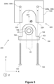
- Figure 2 illustrates the attachment system 100 in a front-on view according to a first embodiment
- Figure 3 illustrates the attachment system of the first embodiment in side view
- the receiving element 120 is a separate element from structures of the landing gear bay 1100, and which can be provided to the landing gear bay 1100 by attachment to those structures, generally designated 1102.
- the attachment element 150 comprises a body 152.
- the body 152 is a load-bearing structure which is receivable by the receiving element 120, and whose precise shape can vary between examples.
- the geometry of the body 152 is described relative to the directional axes x, y, z identified in Figure 2 .
- the y-axis is parallel to the installation direction described in Figure 1 and so, in the context of a landing gear bay facing downwards, the y-axis is a vertical direction.
- the body 152 comprises a head portion 152a and a foot portion 152b.
- the head portion 152a is above the foot portion 152b relative to the y-axis.
- the geometry of the head portion 152a comprises a curved portion, in this example being a semicircular portion, with a radius of curvature in the x-y plane, and a portion comprising straight sides and having constant width, relative to the x-axis.
- the head portion 152a comprises an external surface which comprises curved and straight-sided portions and which can be considered arch-shaped.
- the foot portion 152b is adjacent to the head portion and connected to the portion of the head portion 152a comprising straight sides, such that the semicircular portion forms a distal end of the body 152 relative to the foot portion 152b.
- the foot portion 152b has a width, relative to the x-axis, larger than the head portion 152a such that it comprises protruding portions 158 which extend either side of the width of the head portion 152a.
- the receiving element 120 comprises a recess 122.
- the recess 122 is for receiving the attachment element 150, and the receiving element 120 is for supporting the load of the attachment element 150 which, in use, comprises the attached landing gear 20.
- the recess 122 can be considered to be complementary to the body 152 such that a surface of the recess 122 substantially matches an exterior surface of the body 152.
- the recess 122 comprises a surface which comprises curved and straight-sided portions and which matches the head portion 152a such that, when the head portion 152a is inserted within the recess 122 of the receiving element 120, the recess 122 and head portion 152a of the body 152 form a continuous interface of contacting surfaces.
- the recess 122 is shaped such that the body 152 is inserted into the recess 122 along the y-direction.
- the attachment element 150 is insertable into the receiving element 120 in the installation direction.
- the receiving element further comprises a horizontal bottom surface 129 in the direction of the x-axis which, when the head portion 152a is inserted into and is in contact with the recess 122, contacts the protruding portions 158 of the foot portion 152b.
- the foot portion 152b of the body 152 of the attachment element 150 comprises fastener receptacles 154.
- two receptacles 154 are provided, but more generally a single receptacle or a plurality of receptacles may be present for use with a corresponding number of fasteners.
- the fastener receptacles 154 are through-holes which are aligned in the y-direction, that is, extending from foot portion 152b to head portion 152a of the body 152 in the installation direction.
- the horizontal bottom surface 129 of the receiving element 128 further comprises fastener receptacles 124.
- the fastener receptacles 124 of the receiving element are, in this example, cylindrical boreholes which extend vertically through the receiving element 120, in the direction of the y-axis and hence in the installation direction.
- barrel nuts 126a are disposed within horizontal boreholes 126b.
- Fasteners 130 such as a bolt in this example, are insertable through the fastener receptacles 154 of the attachment element 150 and the fastener receptacles 124 of the receiving element 120.
- the fastener 130 When the attachment element 150 is received by the receiving element 120, the fastener 130 is inserted through the fastener receptacles 154 of the attachment element 150 and the fastener receptacles 124 of the receiving element 120 and engages with the barrel nuts 126a located in the horizontal boreholes 126b.
- the fastener receptacles 154, 124 and contacting surfaces 129, 158 are configured such the fastener 130 is thereby operable to fasten the attachment element 150 to the receiving element 120.
- the receiving element 120 and attachment element 150 comprise features, such as contacting surfaces perpendicular to the direction of the fastener, which enable a fastener 130 to secure the receiving element 120 and attachment element 150 together such that their relative movement is prevented, and so the load of the attachment element 150 and attached landing gear 20 can be supported by the receiving element 120.
- the landing gear 20 is attached to the attachment element 150 by a pivot pin 24.
- the pivot pin 20 is disposed at the end of a portion of the landing gear such as a stay or strut, and allows for a rotational coupling between the attachment element 150 and the landing gear 20.
- the pivot pin 20 may be considered a trunnion or a pintle, but more generally can be understood to represent a rotational coupling between landing gear 20 and the attachment system 100, the precise form of which may vary between examples.
- the pivot pin 24 is received by an aperture 156a, in the body 152 of the attachment element 150.
- the aperture 156a comprises a bearing 156b which further improves the rotational coupling of the attachment element 150 to the landing gear 20.
- the pivot pin 24 may itself comprise elements permitting rotational coupling such that the attachment element 150 itself does not require a bearing.
- the receiving element 120 in this example further comprises a backplate 128.
- the backplate is for attachment of the receiving element 120 to a structural element 1102 of the landing gear bay 1100.
- the backplate 128 extends away from the recess 122 in the x and y plane to increase a surface area of the receiving element 128 in contact with the structural element 1102. This can allow loads to be distributed across a greater area of the structural element 1102 of the landing gear bay 1100.
- Surfaces 129 of the backplate 128 are available for counterboring, such that the backplate 128 and hence receiving element 128 can be fastened to the structural element 1102 of the landing gear bay 1100.
- the backplate 128 may have thicker portions which are specifically designated for counterboring, whereas in other examples all or substantially all of the backplate 128 may be suitable for counterboring.
- the receiving element can first be precisely aligned relative to the structural element 1102 based on the necessary positioning of the landing gear 20 within the landing gear bay 1100, and then the backplate 128 counterbored for fastening to the structural element 1102 once said alignment has occurred. This can allow for a more accurate installation of the landing gear 20.
- the use of adhesives or alternative fastening mechanisms may be used in addition to or alternatively to fastening the backplate 128 to the structural element 1102.
- the receiving element 120 may not have a backplate 128, but fastening of the receiving element 120 to the structural element 1102 provided by additional fastener receptacles, for example.
- the attachment system 100 further comprises a spacing element 330 which can be provided between the receiving element and the structural element 1102.
- the spacing element can aid with aligning the receiving element 120 precisely relative to the structural element 1102 such that the landing gear 20 is correctly positioned within the landing gear bay 1100 once installed.
- the spacing element 330 can be considered to be a shim, for example.
- the attachment system 100 may comprise a plurality of spacing elements 330 having different respective thicknesses, for example, such than an engineer can select an appropriately sized spacing element 330 for use in the installation.
- FIG. 4 schematically illustrates the attachment element 150 in side view.
- the pivot pin 24 may comprise a flared end 27 which prevents it from sliding out of the aperture 156a and bearing 156b as the flared end 27 is wider than the aperture 156a and contact surfaces of the body 152 if the pivot pin 24 is pulled in a direction out of the aperture 156a.
- the flared end 27 may be integrated within the pivot pin 24 itself, or may be a separate attachment attached to the end of the pivot pin 24 during the installation process. Accordingly, in some examples the attachment element 150 may be attached to the pivot pin 24 prior to the pivot pin 24 being attached to the landing gear 20.
- Figure 5 illustrates the attachment system 100 in a front-on view according to a second embodiment.
- the receiving element herein designated 220
- the receiving element is formed within a structural element of the landing gear bay 1100, designated 1104.
- the attachment element 150 may be the same as or substantially similar to those examples described for the first embodiment.
- the structural element 1104 in which the receiving element 220 of the second embodiment is formed may correspond to the structural element 1102 to which the receiving element 120 of the first embodiment is attached.
- both structural elements 1102, 1104 may be side panels of the landing gear bay.
- a recess 222 is formed in the structure 1104 of the landing gear bay 1100.
- the structure 1104 is a side panel of the landing gear bay.
- the recess 222 is a mousehole formed in the structure 1104.
- the structure 1104 is initially manufactured with the recess 222, whereas in other examples an existing structure 1104 is modified to include the recess 222.
- the recess 222 is complementary to the shape of the body 152 of the attachment element 150. Therefore, the recess 222 in this example is substantially arch-shaped, but in other examples may have other shapes according to the attachment element 150 with which it is to be used.
- the structure 1104 also comprises fastener receptacles 224 which are for receiving the fasteners 130 provided through the fastener receptacles 154 of the attachment element 150. Corresponding horizontal boreholes 226a and barrel nuts 126b are provided, the barrel nuts 126b for engaging with the fasteners 130.
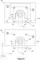
- Figure 6 schematically illustrates the attachment system 100 of the first embodiment, and the attachment system 200 of the second embodiment each in assembled form, with the attachment element 150 inserted into the receiving element 120, 220 and the fastener 130 fastened to secure the attachment element 150 to the receiving element 120, 220.
- the landing gear 20 is attached by the attachment system 100 to the structure 1102 of the landing gear bay 1100.
- the landing gear 20 is attached by the attachment system 200 to the structure 1104 of the landing gear bay 1100.
- the landing gear 20 is movably coupled to the landing gear bay 1100 such that the landing gear 20 can be reoriented to allow for retraction into a stowed position in the landing gear bay 1100 and deployment from the landing gear bay 1100.
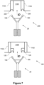
- Figure 7 schematically illustrates the attachment system 100 of the first embodiment, and the attachment system 200 of the second embodiment, each within view of the landing gear bay 1000.
- Each embodiment can allow the installation of the landing gear 20 in the installation direction as the attachment element 150 is received by the receiving element 120, 220 in the installation direction, and subsequently fastened by the fastener 130 (not shown in Figure 7 ).
- the attachment system 100 of the first embodiment is attached to the structural element 1102 and protrudes into the landing gear bay 1100.
- the attachment system 200 of the second embodiment is formed within the structural element 1104 and so the receiving element 220 may be aligned with the boundary of the landing gear bay.
- the structural element 1102 of the landing gear bay 1100 described for the first embodiment and structural element 1102 of the landing gear bay 1100 described for the second embodiment may otherwise be the same structural element, beyond the differences described previously.
- both attachment systems 100, 200 may use a side panel of the landing gear bay 1100 as the structural element to which they are secured or formed in.
- first and second attachment element are attached to main fitting pintles of the landing gear
- a third and fourth attachment element are attached to dragstay pintles of the landing gear, each of which can be a portion 22 of the landing gear 20.
- First, second, third and fourth receiving elements are correspondingly positioned within the landing gear bay, either as per the first embodiment or as per the second embodiment.
- a mixture of receiving elements may be used, for example wherein the dragstay pintle attachment elements are received by receiving elements of the first embodiment and the main fitting pintle attachment elements are received by receiving elements of the second embodiment.
- Figures 8a-f illustrate variations on the attachment element 150 and corresponding variations of the receiving element 120, 220.
- the variations are equally applicable to the first embodiment and the second embodiment.
- the skilled person will understand, upon reading the following description of the figures, how each described variation could be combined with the other described variations, such that the illustrated variations do not represent an exhaustive list but rather each highlights a particular feature which may be included in embodiments of the attachment system 100, 200. Accordingly, a "first" example here is labelled “first” in reference to the collection of variations depicted by Figures 8a-f , rather than being a first in the context of the entire description.
- Figure 8a illustrates a side-view of a first example of the attachment element body 152-1 in which the body 152-1 comprises parallel sides. That is, top and bottom sides of the body 152-1 are parallel, wherein top and bottom are in reference to the y -axis, or the installation direction. Similarly, front and back sides are parallel, wherein front and back is in reference to sides at different positions along the z -axis.
- a first example of the recess 122-1 of the receiving element 120 also comprises parallel sides in the same cross-section, as the recess 122-1 has a complementary shape to the first example of the attachment element body 152-1.
- Figure 8b illustrates a side view of a second example of the attachment element body 152-2 in which the body 152-2 is tapered.
- the entire body 152-2 is illustrated as being tapered in the cross-section presented by Figure 8b but more generally, just a portion of the attachment element body 152-2 might be tapered.
- a thickness of the entire body 152-2 relative to the z- axis, as measured between the front and back sides decreases along the height of the attachment element body 152-2.
- the top of the attachment element body 152-2, the point highest on the z-axis and which can be considered to extend furthest into the recess 122 of the receiving element 120, is narrower than the bottom of the attachment element body 152-2.
- the attachment element body 152-2 comprises opposite sides which are not parallel.
- a second example of the recess 122-2 comprises correspondingly drafted sides which are of complementary shape to the second example of the attachment element body 152-2.
- Providing a taper in this manner can assist insertion of the attachment element 150 into the receiving element 120 because the top of the attachment element body 152-2 is narrower than an opening of the recess 122-2 into which the attachment element body 152-2 is inserted, which can make it easier to insert. Because the recess 122-2 is correspondingly drafted to the tapered attachment element body 152-2, once the attachment element 150 is fully inserted into the receiving element 120 a contacting interface is formed between recess 122-2 and the attachment element body 150-2. Forces can be transferred across this contacting interface.
- Figure 8c illustrates a third example of an attachment element 150 in which the attachment element body 152-3 is provided with a flange 153.
- the flange is provided on the top surface of the attachment element body 152-3, but other variations are possible, as illustrated by Figures 8e and 8f and described shortly.
- the flange 153 is tapered, but in other examples it may comprise parallel sides. That is, similar to the tapered profile of the second example of attachment element body 152-2, in the y -direction, or the installation direction, the thickness of the flange 153 decreases, the thickness being in the front-back direction, or the z-direction.
- a third example of the recess 122-3 comprises a groove 123 which corresponds to the flange 153, such that when the attachment element body 152-3 is inserted into the recess 122-3, the flange 153 is received by the groove 123.
- the flange can further improve distribution of forces between the attachment element 150 and the receiving element 120 by reacting to lateral loads placed upon the attachment element, for example, and can also serve as a confirmation of proper insertion of the attachment element 150 within the receiving element 120 by ensuring the attachment element 150 is stood-off from the receiving element 120 until the flange 153 is inserted into the groove 123.
- Figure 8d illustrates a fourth example of an attachment element body 152-4 in front-on view.
- the attachment element body 152-4 of Figure 8d does not comprise a curved portion.
- the attachment element body 152-4 comprises a tapered profile in the front-on view. That is, the lateral sides, relative to the x-axis, are non-parallel and change in thickness relative to the height of the attachment element body 152-4.
- the tapered profile described in Figure 8b towards the top of the attachment element body 152-4 the attachment element body 152-4 is thinner whilst towards the bottom of the attachment element 152-4 the attachment element body 152-4 is thicker, in this example in the direction of the x-axis.
- attachment element body 152 can be tapered in both the x -axis and the y -axis, in other words combining the features of Figure 8a with Figure 8d . Whilst not depicted in Figure 8d , it will be appreciated that the receiving element is correspondingly drafted to be complementary with the tapered attachment element body 152-4.
- Figure 8e illustrates a fifth example of an attachment element 150 which comprises an attachment element body 152 substantially similar to that depicted in Figures 2-6 , but comprising multiple flange portions 153a, 153b, 153c.
- the multiple flange portions are distributed around the external surface of the attachment element body 152.
- a first flange portion 153a is formed on a first lateral side of the attachment element body 152.
- a second flange portion 153b is formed on a top side of the attachment element body 152.
- a third flange portion 153c is formed on a second lateral side of the attachment element opposite the first lateral side, such that the attachment element body 152 is between the first flange portion 153a and the third flange portion 152b.
- the receiving element 120 (not pictured in Figure 8e ) comprises corresponding first, second and third grooves to respectively receive a flange portion 153a-c.
- the second flange portion 153b can be guided into position in its receiving groove as the first and third flange portions 153a,c are received by their respective grooves during insertion of the attachment element 150 into the receiving element 120. This can further improve the ease of installation.
- each flange is itself curved in the x-y plane.
- This curve can further aid insertion of the flange into the groove in a similar manner to that described for the taper profile in Figures 8b-d .
- the curved flanges may, in examples, also comprise a taper profile in the back-front direction, for example.
- Figure 8f describes a fourth example of a flange 153-d which can be provided to the attachment element body 152.
- the flange is provided around a majority of the attachment element body 152, and can be thought of as providing a perimeter around the attachment element body 152.
- the recess of the receiving element is formed by surfaces in the x and z planes, such that an inserted attachment element is prevented from movement in x and z directions by the surrounding recess surfaces.
- the receiving element encapsulates the attachment element in x and z directions when inserted, such as the examples illustrated in Figures 8a-8c .
- the front and back sides of the attachment element are flush with front and back sides of the receiving element, such as that visible in the cross-section of Figure 11b . That is, the front and back sides of the attachment element are aligned with the front and back sides of the attachment element relative to the z axis.
- motion in the z-axis can be prevented by the presence of flanges and grooves which are located more internally to the recess and attachment element, as described for figures 8c, 8e and 8f .
- Having flush front and back surfaces of the receiving element and attachment element can reduce a spatial footprint of the attachment system in the z-direction, for example, which can increase space available in the landing gear bay 1100.
- Figures 9 and 10 illustrate additional elements which, in examples, may be provided within the attachment system 100, 200 to assist in the installation of the landing gear 20.
- counterweight elements 160 are provided on the attachment element 150.
- the attachment element 150 in being movably coupled to the landing gear 20 by the pivot pin 24, may experience reorientation during installation of the landing gear 20, such as when the landing gear 20 is lifted into the landing gear bay 1100.
- the counterweight elements 160 are provided to reduce or prevent reorientation of the attachment element 150 and thereby ensure that the attachment element 150 is straightforwardly received by the receiving element 120.
- the counterweight elements 160 may be provided below the coupling point formed by pivot pin 24, bearing 156b and aperture 156a of the attachment element 150. This can lower the centre of mass of the attachment element 150 and increase the mass of the attachment element 150 to thereby increase a period of oscillation of the attachment element 150, improving its stability during the installation process.
- the counterweight elements 160 in being provided on the attachment element 150 and being pulled downwards by gravity, indicated by arrow g , can thereby ensure the attachment element is correctly oriented relative to the installation direction, even given that the attachment element is movably connected to the landing gear 20.
- the counterweight elements 160 can be considered to be retaining elements, which retain the components of the attachment system within an orientation such that the attachment element 150 is insertable within the receiving element 120.
- retaining elements may be additionally or alternatively provided.
- a spring may be attached between the landing gear 20 and the attachment element 150. The spring, in being compressible and expandible, allows for a degree of movement of the attachment element 150 relative to the landing gear 20, but returns the attachment element 150 to a neutral position, which can be arranged to align with the receiving element 120. This can allow for small adjustments for the attachment element 150 during insertion into the receiving element 120, whilst preventing or resisting larger reorientations which would prevent insertion of the attachment element 150 into the receiving element 120.
- a pair of magnets 164a, 164b are provided in the example of Figure 10 .
- a first magnet 164a of the pair is provided on the receiving element 120
- a second magnet 164b of the pair is provided on the attachment element 150.
- the first magnet 164a is provided towards the opening of the recess 122
- the second magnet 164b is provided on the top of the attachment element 150 such that, as the attachment element 150 approaches the receiving element 120 for insertion, the first magnet and the second magnet attract one another and thereby help guide the attachment element 150 into the receiving element 120.
- a magnet may be provided on the receiving element, whilst the attachment element comprises a paramagnetic material for attraction to the magnet.
- a pair of guidance rods 162a, 162b are provided in the example of Figure 10 .
- the guidance rods 162a, 162b are attached to the receiving element 120 and extend in a vertical direction, that is in the y-direction, or in the direction of installation.
- the first guidance rod 162a is positioned such that it can received by the fastener receptacle 154. Once received by the fastener receptacle 154, the guidance rod 162a acts to guide the attachment element 150 to insertion into the receiving element 120.
- the first guidance rod 162a is removable, such that once the guidance element 150 is inserted into the receiving element 120, the guidance rod 162 can be removed and replaced by the fastener 130 to fasten the attachment element 150 to the receiving element 120.
- the second guidance rod 162b is positioned such that it can be received by a dedicated guidance rod receptacle 166 provided on the attachment element 150.
- the second guidance rod 162b may also be temporary, being removed once the attachment element 150 is inserted into the receiving element 120, or may be permanent, and serve the sole purpose of guiding the attachment element 150 into the receiving element 120, for example, but remaining in place once inserted.
- magnets may be provided to the guidance rods and the receptacles, for example, to aid insertion of the guidance rods through their respective receptacles.
- Figures 11a and 11b illustrate further features which may be provided to the attachment system 200 of the second embodiment. It will be appreciated that, in examples, providing the receiving element 120 directly within a structural element 1104 of the landing gear bay 1100 may disrupt the external aircraft skin 1110. In the example of Figures 11a and 11b , a portion of the aircraft skin 111 1a has been removed such that the attachment element 150 can be inserted into the receiving element 120. Accordingly, a replacement aircraft skin portion 1111b is provided after insertion of the attachment element 150 into the receiving element 120. The replacement aircraft skin portion 1111b is attached to the bottom of the attachment element 150 such that the replacement aircraft skin portion 111 1b is coplanar with the external aircraft skin 1110. This can improve the aerodynamic performance of the aircraft around the landing gear bay area.
- a skin doubler 1112 can be provided to further reinforce the replacement aircraft skin portion 1111b.
- a load transfer cap 170 can be provided to be fastened to and transfer load between any of the external aircraft skin 1110, and replacement aircraft skin portion 11 11b, and the structural element 1104 and the attachment element 150.
- the attachment system may comprise other components for local reinforcement of the surrounding structures, for example other structural elements of the landing gear bay, the aircraft exterior skin, or a combination thereof.
- the receiving element 120 and attachment element 150 may be formed of metal or composite materials, for example.
- the structural element 1102, 1104 of the landing gear bay 1100 is also formed from the same metal or composite materials.
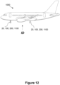
- Figure 12 illustrates the aircraft 1000 comprising the landing gear 20 installed into the landing gear bay 1100 by the attachment system 100, 200 described herein.
- the aircraft 1000 in comprising the attachment systems 100, 200, can be manufactured more quickly due to the decreased complexity of the installation process. Furthermore, should maintenance of the aircraft 1000 be required.
- the attachment system 100, 200 is provided in the nose landing gear of the aircraft and the attachment system 100, 200 is attached to side panels of the nose landing gear bay, or the receiving element 220 is formed within side panels of the nose landing gear bay.
- the attachment system 100, 200 described herein may be provided as a kit of parts, for example, and attachment elements may be provided separately to receiving elements, for example.
- different attachment elements may be used with a receiving element, and different receiving elements may be used with an attachment element.
- This can allow an attachment or receiving element to be chosen based on the landing gear or aircraft, for example.
- Providing the attachment and receiving element separately can allow for replacement attachment or receiving elements to be provided for maintenance purposes, for example.
- the fasteners for fastening the attachment element to the receiving element have been in the form of a bolt passing through the attachment element and engaging a barrel nut provided in the receiving element.
- the skilled person will appreciate that other fasteners may be provided which are similar installable and securable in the installation direction.
- the fasteners have been provided in the installation direction. However, this does not preclude other fasteners being provided, for example once the attachment element is initially secured by the receiving element, to reinforce the aforementioned fasteners provided in the installation direction.
Landscapes
- Engineering & Computer Science (AREA)
- Mechanical Engineering (AREA)
- Aviation & Aerospace Engineering (AREA)
- Gears, Cams (AREA)
- Retarders (AREA)
- Gear Transmission (AREA)
- General Details Of Gearings (AREA)
- Connection Of Plates (AREA)
Abstract
Disclosed is an attachment system for installing a landing gear into a landing gear bay of an aircraft. The attachment system comprises an attachment element configured to be attachable to the landing gear; and a receiving element configured to receive the attachment element and secure the landing gear within the landing gear bay. The receiving element is configured such that the attachment element is insertable into the receiving element from an installation direction, and the attachment element is configured to receive, in the installation direction, a fastener to fasten the attachment element to the receiving element.
Description
- The present invention relates to landing gears for aircraft, and more specifically to systems for installation of landing gears into a landing gear bay of an aircraft.
- The installation of aircraft landing gears into a landing gear bay can be a complex and time-consuming process in which the landing gear is aligned and fastened to internal structures of the landing gear bay. The installation of the landing gear typically requires multiple and often iterated operations to ensure proper alignment with the aircraft body, and can also include dismantling and reconstructing of various components of the landing gear. It is desirable to improve the installation of aircraft landing gears.
- A first aspect of the present invention provides an attachment system for installing a landing gear into a landing gear bay of an aircraft. The attachment system comprises an attachment element configured to be attachable to a pivot pin of the landing gear, and a receiving element configured to receive the attachment element when attached to the pivot pin and to secure the landing gear within the landing gear bay. The pivot pin is configured to form a rotational coupling between the landing gear and the attachment element, and the receiving element is configured such that the attachment element is insertable into the receiving element from an installation direction when attached to the pivot pin. The attachment element is further configured to receive, in the installation direction, a fastener to fasten the attachment element to the receiving element.
- It is an insight of the inventors to recognise an installation direction, which can be considered a general direction in which the landing gear is moved into a landing gear bay during an installation process, and to develop an attachment system which is aligned with this installation direction. Typically, the landing gear bay is oriented downwards in that it is facing towards the ground during the assembly process of the aircraft, and the landing gear is therefore typically lifted vertically into the landing gear bay during installation. By allowing the attachment element to be inserted into the receiving element in the installation direction, the attachment system is readily operable at the installation stage and the need for further operations and reorientations to engage the attachment element with the receiving element can therefore be avoided.
- Furthermore, because the attachment element is configured to receive the fastener in the installation direction, the attachment element can be fastened to the receiving element in a relatively straightforward manner. For example, the landing gear can be lifted into the landing gear bay in the installation direction, the attachment element inserted into the receiving element in the installation direction, and the attachment element fastened to the receiving element in the installation direction. Thus, the installation operations as described above can be performed from the same direction. This can prevent an engineer, or tools used in the installation process, from needing to reorient themselves during the installation process, which can improve installation speed. Furthermore, it can reduce a risk of unwanted movement of the landing gear relative to the landing gear bay which might result from such movement of engineer or tools, thereby improving the reliability of the installation process and further decrease time taken to perform the installation process.
- The attachment system can be contrasted from previous methods or systems for installing landing gears, in which the landing gear is lifted into the landing gear bay and then attached to structures of landing gear bay by fasteners provided perpendicular to the installation direction, for example, which can require an operator to reposition, and/or require disassembly and subsequent reassembly of components such as pintles, bearing inserts, and receiving brackets to install the landing gear. Rather, lifting of the landing gear into the landing gear bay, engagement of the receiving element with the attachment element, and fastening of the receiving element to the attachment element can occur in one relatively continuous stage, all occurring in the installation direction.
- As used herein, a landing gear can be understood as an undercarriage of the aircraft, for example, and which facilitates movement along the floor when the aircraft is on the ground. As used herein, a landing gear bay can be understood as a cavity provided in an aircraft fuselage, into which the landing gear can be stowed during flight. As used herein, a pivot pin can be understood as a pintle pin or a trunnion, for example, which allows for rotational movement during extraction and retraction of the landing gear, for example when a landing gear is being deployed or stowed into the landing gear bay. As used herein, the receiving element and attachment element can be understood to be, respectively, a bracket, or a recess, or a mousehole, or a cut-out, as appropriate, and the attachment element can be understood as an insert, insertable to the receiving element. As used herein, a fastener can be understood as a device which mechanically affixes, or joins, two or more objects together. For example, a fastener can be understood to comprise any one or more of nuts, bolts, screws, clips, ties, anchors, latches, clasps, staples, retainers, and rivets.
- Optionally, the attachment element may comprise a shape and the receiving element a corresponding, or complementary shape, wherein the shapes may contribute to ease of installation by, for example, aiding self-alignment of the receiving element and the attachment element during insertion, or contribute to distribution of loads, or forces, between the receiving element and the attachment element, or both.
- Accordingly, the attachment element may in some examples comprise a tapered portion configured to be insertable into a correspondingly drafted portion of the receiving element. A tapered portion can refer to a portion comprising a first width at a first distance along an axis, and a second width at a second distance along the axis, the first width being different to the second width. The tapered portion may be chamfered, or bevelled, for example. The tapered portion may be a wedge shaped. The presence of a tapered portion of the attachment element and a correspondingly drafted portion of the receiving element can help during insertion of the attachment element into the receiving element. For example, the tapered portion and correspondingly drafted portion can act as a guide such that, during installation, the attachment element is positioned correctly relative to the receiving element. In this sense, the tapered portion and the correspondingly drafted portion can result in self-alignment of the attachment element relative to the receiving element without requiring external assistance from an engineer or tool, for example. Substantially all of the attachment element may be considered tapered, or only a discrete portion of the attachment element may be considered tapered.
- Accordingly, in some examples, the attachment element comprises a curved portion and the receiving element comprises a correspondingly curved portion. A curved portion can allow for forces experienced by the attachment element to be readily and evenly transferred to the receiving element, for example. An even transfer of force can reduce a risk that a portion of the receiving element and/or attachment element fails due to excessive loads, for example, and can accordingly improve a lifespan of the receiving element and/or attachment element. Substantially all of the attachment element may be considered curved, or only a discrete portion of the attachment element may be considered curved.
- Accordingly, in some examples, the curved portion of the attachment element is semicircular. In other examples, the curved portion may comprise a major or minor segment of a circle, such that a curved exterior of the attachment element is an arc of a circle. In other examples, the curved portion may be a major minor segment of an ellipse, such that a curved exterior of the attachment element is an arc of an ellipse. In examples, the attachment element may comprise a plurality of curved portions which combined form a composite structure of curved portions, such as a combination of semicircles, for example. A circular shape can allow for improved load transmission of any combination of upward, forward and aft loads originating from the landing gear.
- The attachment element may be tapered and curved in different cross-sectional planes, for example. In a first cross-section, the attachment element may have straight sides but nevertheless be tapered. In a second cross-section, such as perpendicular to the first, the attachment element may have curved sides.
- Accordingly, in some examples, the attachment element comprises a flange and the receiving element comprises a corresponding groove for receiving the flange, the flange and groove configured to distribute forces between the attachment element and the receiving element. In examples, the flange may be of constant thickness and be disposed around an external surface of the attachment element which interfaces with the receiving element. In other examples, the flange may be provided at a specific portion, or specific portions, of the external surface of the attachment element which interfaces with the receiving element. Similarly, the groove may be provided around an internal surface of the receiving element for interfacing with the exterior surface of the attachment element, whereas in other examples the groove is provided at a specific portion, or specific portions, of the internal surface of the receiving element and corresponding with the location of the flange of the attachment element. In examples, the flange and groove are the tapered portions and/or curved portions of the attachment element and receiving element.
- Optionally, the attachment element further comprises a bearing element for receiving the pivot pin of the landing gear. The bearing element can improve the rotational coupling of the pivot pin to the attachment element such that the landing gear can be more easily deployed and retracted, for example. The bearing element may be a bushing, for example.
- Optionally, the installation direction extends vertically through an opening of the landing gear bay. The landing gear can thereby be straightforwardly lifted into the landing gear bay, with the landing gear bay oriented in the same direction as it would be during normal operation of the aircraft. This can reduce the need for reorientation of the aircraft during the installation procedure.
- Optionally, the receiving element is attachable to a structural element of the landing gear bay. That is, the receiving element is a separate structure to the landing gear bay which can be attached to a structural element of the landing gear bay. This can allow for retrofitting, for example, wherein the receiving element is attachable to a pre-existing landing gear bay and hence the attachment system usable within a pre-existing aircraft.
- Optionally, where the receiving element is attachable to a structural element of the landing gear bay, the structural element of the landing gear bay is a side panel of the landing gear bay. In other examples, the attachment may be attachable to a rib or spar, for example.
- Optionally, the receiving element comprises a surface for counterboring for fastening the receiving element to the structural element of the landing gear bay. This can allow the receiving element to be positioned relative to the structural element, and once correctly positioned, a hole formed such that a fastener can be received for fastening the receiving element to the structural element of the landing gear bay, for example. This can simplify installation by reducing orientational constraints as the receiving element is more flexibly positioned prior to fastening.
- Optionally, the attachment system further comprises a spacing element disposable between the receiving element and the structural element of the landing gear bay. Such a spacing element may be a shim, for example. This can allow for the receiving element to be positioned more accurately relative to the structural element of the landing gear bay, such that the landing gear can accordingly be positioned properly relative to the landing gear bay.
- Optionally, the receiving element is formed within a structural element of the landing gear bay. That is, the receiving element may be monolithically integrated within, or otherwise integrated within a volume of, a structural element of the landing gear bay. In examples, the receiving element may be a mousehole, or recess, or cut-out, formed in the structural element of the landing gear bay. This can reduce a spatial footprint of the attachment system because the receiving element is provided within the same volume as a structural element of the landing gear bay, which can reduce space required by the attachment system to be installed into the landing gear bay.
- Optionally, where the receiving element is formed within a structural element of the landing gear bay, the structural element is a side panel of the landing gear bay. In other examples, the structural element may be a rib or spar, for example.
- Optionally, the attachment system further comprises an aircraft skin portion attachable to the attachment element such that, when the attachment element is received by the receiving element, the aircraft skin portion is coplanar with an exterior skin of the aircraft. The receiving element being formed within a structural element of the landing gear bay may involve removal of a portion of the exterior skin of the aircraft until the landing gear is installed. A corresponding skin portion may be attached, co-planar with the exterior skin, to thereby extend the exterior skin back into this removed portion. This can improve the aerodynamic performance of the exterior skin of the aircraft.
- Optionally, the attachment system further comprises a load transfer cap attachable between the aircraft skin portion and the structural element of the landing gear bay and configured to distribute a load between the aircraft skin portion and the structural element of the landing gear bay. This can improve load transfer across the aircraft skin which may reduce a risk of damage of the skin due to excessive loads, for example.
- Optionally, two or more of the attachment element, the receiving element, and the structural element of the landing gear bay are each formed of a same material. The same material can mean that the coefficient of thermal expansion is the same for each of the attachment element, the receiving element, and the structural element of the landing gear bay, for example. This can mean that, in response to a change in temperature, such as a change in temperature experienced due to increase or decrease in altitude, each of the attachment element, the receiving element, and the structural element of the landing gear bay may expand or contract by a same proportion. This can reduce a risk of inducing unwanted strains through particular elements of the landing gear bay, for example, and in turn improve an operational lifespan of the attachment system.
- Optionally, the attachment system further comprising a retaining element configured to retain the attachment element in an installation orientation relative to the landing gear. This can allow the attachment element to be oriented correctly initially, and retain that position during the installation procedure. For example, an operator could initially align the attachment element relative to the orientation of the receiving element, prior to the landing gear being lifted into the landing gear bay. The retaining element can retain the attachment element in said orientation as the landing gear is lifted into the landing gear bay, such that the attachment element is receivable by the receiving element without requiring further orientational adjustments, or requiring only minor orientational adjustments, for example. In examples, the retainment element may be a spring connected between the attachment element and the landing gear and configured to allow for a degree of motion but nevertheless return the attachment element to a specific orientation relative to the landing gear.
- Optionally, when the installation direction extends vertically through an opening of the landing gear bay, the retaining element is a weight disposed in the attachment element and configured to retain the attachment element in a vertical orientation.
- Optionally, the attachment system further comprises a guidance element disposable on at least one of the attachment element and retaining element and configured to aid movement of the attachment element along the installation direction such that it can be received by the retaining element. The guidance element may be a temporary element which is provided during the installation process and subsequently removed, for example. The guidance element may be a rod provided on the receiving element and positioned to pass through the fastener receptacle, for example, before being removed and replaced by the fastener once the attachment element has been received by the receiving element. In other examples, it may be a permanent element, but play no further role beyond guiding the attachment element along the installation direction during the installation process. The guidance element may comprise a magnet, or plurality of magnets, and corresponding magnetic surface, for example, distributed between the receiving element and the guidance element, which act to attract the attachment element in a specific direction towards the receiving element and thereby guide the attachment element to being received by the receiving element.
- A second aspect of the present invention provides an attachment element for installing a landing gear into a landing gear bay of an aircraft. The attachment element comprises a body configured to be attachable to a pivot pin of the landing gear, the pivot pin forming a rotational coupling between the landing gear and the attachment element, the body further configured to be insertable, in an installation direction, into a receiving element of the landing gear bay; and a receptacle for a fastener for fastening the body to the receiving element; wherein the receptacle is configured to receive the fastener from the installation direction.
- A third aspect of the present invention provides a receiving element for installing a landing gear into a landing gear bay of an aircraft. The receiving element comprises a recess configured to receive a body of an attachment element attached to a pivot pin of the landing gear, the recess configured such that the body is insertable into the recess from an installation direction, the receiving element configured to receive a fastener for fastening the attachment element to the receiving element, the receiving element configured to receive the fastener in the installation direction.
- It will be appreciated that benefits described previously for the first aspect of the invention are equally applicable to the second and third aspects of the invention where appropriate.
- A fourth aspect of the present invention provides an aircraft comprising the attachment system of the first aspect, the attachment element of the second aspect or the receiving element of the third aspect.
- In comprising the attachment system, the attachment element, or the receiving element, the landing gear can be more straightforwardly installed and uninstalled. Accordingly, such an aircraft can be manufactured more quickly due to the simplified installation process described above. Additionally or alternatively, it can be more straightforward to perform maintenance on the aircraft and thereby can reduce operational downtime of the aircraft, for example, as the landing gear is more readily removed and reinstalled.
- Embodiments of the invention will now be described, by way of example only, with reference to the accompanying drawings, in which:
-
Figure 1 shows a schematic side-view of an attachment system, according to an embodiment of the present invention; -
Figure 2 shows a schematic view of an attachment system in a front-view, according to an embodiment of the present invention; -
Figures 3 and 4 show schematic views of the attachment system in a side-view, according to an embodiment of the present invention; -
Figure 5 shows a schematic view of an attachment system in a front view, according to a further embodiment of the present invention; -
Figures 6 and7 show schematic views of attachment systems according to embodiments of the present invention; -
Figures 8a-f shows schematic views of attachment elements and receiving elements according to embodiments of the present invention; -
Figures 9 and 10 show schematic views of guidance elements and retaining elements according to embodiments of the present invention; -
Figures 11a, 11b show schematic views of the aircraft skin and an attachment system according to an embodiment of the present invention; -
Figure 12 illustrates an aircraft comprising the attachment system of the present invention. -
Figure 1 schematically illustrates an example of anattachment system 100 according to an embodiment of the present invention. - Considering, first, the general purpose of the attachment system 100: the
attachment system 100 is for installing alanding gear 20 into alanding gear bay 1100 of anaircraft 1000. Theattachment system 100 comprises anattachment element 150 which is attached to thelanding gear 20, and a receivingelement 120 which is arranged within thelanding gear bay 1100. Thelanding gear 20 can be installed by lifting thelanding gear 20 along an installation direction, labelled inFigure 1 by the indicative arrow ID, into thelanding gear bay 1100. Theattachment element 150 is insertable into the receivingelement 120, to which it is fastened by a fastener 130 (not illustrated inFigure 1 ) to secure thelanding gear 20 within thelanding gear bay 1100. The receivingelement 120 andattachment element 150 are configured such that the insertion of theattachment element 150 to the receivingelement 120 is in the installation direction and such that the fastener is received in the installation direction. Theattachment element 150 is attached to apivot pin 24 located at the end of aportion 22 of thelanding gear 20, theportion 22 being a part of thelanding gear 20 to typically form the attachment point of a landing gear into a landing gear bay, such as a main fitting or a drag stay, for example. - Examples of the
attachment element 150 and the receivingelement 120 of theattachment system 100 will now be described in more detail. -
Figure 2 illustrates theattachment system 100 in a front-on view according to a first embodiment, andFigure 3 illustrates the attachment system of the first embodiment in side view. In the first embodiment, the receivingelement 120 is a separate element from structures of thelanding gear bay 1100, and which can be provided to thelanding gear bay 1100 by attachment to those structures, generally designated 1102. - The
attachment element 150 comprises abody 152. Generally, thebody 152 is a load-bearing structure which is receivable by the receivingelement 120, and whose precise shape can vary between examples. The geometry of thebody 152 is described relative to the directional axes x, y, z identified inFigure 2 . The y-axis is parallel to the installation direction described inFigure 1 and so, in the context of a landing gear bay facing downwards, the y-axis is a vertical direction. In this example, thebody 152 comprises ahead portion 152a and afoot portion 152b. Thehead portion 152a is above thefoot portion 152b relative to the y-axis. The geometry of thehead portion 152a comprises a curved portion, in this example being a semicircular portion, with a radius of curvature in the x-y plane, and a portion comprising straight sides and having constant width, relative to the x-axis. In other words, thehead portion 152a comprises an external surface which comprises curved and straight-sided portions and which can be considered arch-shaped. Thefoot portion 152b is adjacent to the head portion and connected to the portion of thehead portion 152a comprising straight sides, such that the semicircular portion forms a distal end of thebody 152 relative to thefoot portion 152b. Thefoot portion 152b has a width, relative to the x-axis, larger than thehead portion 152a such that it comprises protruding portions 158 which extend either side of the width of thehead portion 152a. - The receiving
element 120 comprises arecess 122. Generally, therecess 122 is for receiving theattachment element 150, and the receivingelement 120 is for supporting the load of theattachment element 150 which, in use, comprises the attachedlanding gear 20. Therecess 122 can be considered to be complementary to thebody 152 such that a surface of therecess 122 substantially matches an exterior surface of thebody 152. In this example, therecess 122 comprises a surface which comprises curved and straight-sided portions and which matches thehead portion 152a such that, when thehead portion 152a is inserted within therecess 122 of the receivingelement 120, therecess 122 andhead portion 152a of thebody 152 form a continuous interface of contacting surfaces. As seen inFigure 2 , therecess 122 is shaped such that thebody 152 is inserted into therecess 122 along the y-direction. In other words, theattachment element 150 is insertable into the receivingelement 120 in the installation direction. The receiving element further comprises ahorizontal bottom surface 129 in the direction of the x-axis which, when thehead portion 152a is inserted into and is in contact with therecess 122, contacts the protruding portions 158 of thefoot portion 152b. - The
foot portion 152b of thebody 152 of theattachment element 150 comprisesfastener receptacles 154. In this example, tworeceptacles 154 are provided, but more generally a single receptacle or a plurality of receptacles may be present for use with a corresponding number of fasteners. The fastener receptacles 154 are through-holes which are aligned in the y-direction, that is, extending fromfoot portion 152b tohead portion 152a of thebody 152 in the installation direction. Thehorizontal bottom surface 129 of the receivingelement 128 further comprisesfastener receptacles 124. The fastener receptacles 124 of the receiving element are, in this example, cylindrical boreholes which extend vertically through the receivingelement 120, in the direction of the y-axis and hence in the installation direction. At a distal end of thefastener receptacles 124 of the receiving element, located away from thehorizontal bottom surface 129,barrel nuts 126a are disposed withinhorizontal boreholes 126b.Fasteners 130, such as a bolt in this example, are insertable through thefastener receptacles 154 of theattachment element 150 and thefastener receptacles 124 of the receivingelement 120. When theattachment element 150 is received by the receivingelement 120, thefastener 130 is inserted through thefastener receptacles 154 of theattachment element 150 and thefastener receptacles 124 of the receivingelement 120 and engages with thebarrel nuts 126a located in thehorizontal boreholes 126b. The fastener receptacles 154, 124 and contactingsurfaces 129, 158 are configured such thefastener 130 is thereby operable to fasten theattachment element 150 to the receivingelement 120. More generally than the specific example illustrated here, it will be appreciated that the receivingelement 120 andattachment element 150 comprise features, such as contacting surfaces perpendicular to the direction of the fastener, which enable afastener 130 to secure the receivingelement 120 andattachment element 150 together such that their relative movement is prevented, and so the load of theattachment element 150 and attachedlanding gear 20 can be supported by the receivingelement 120. - The
landing gear 20 is attached to theattachment element 150 by apivot pin 24. Thepivot pin 20 is disposed at the end of a portion of the landing gear such as a stay or strut, and allows for a rotational coupling between theattachment element 150 and thelanding gear 20. In examples, thepivot pin 20 may be considered a trunnion or a pintle, but more generally can be understood to represent a rotational coupling betweenlanding gear 20 and theattachment system 100, the precise form of which may vary between examples. Generally, thepivot pin 24 is received by anaperture 156a, in thebody 152 of theattachment element 150. In this example, theaperture 156a comprises a bearing 156b which further improves the rotational coupling of theattachment element 150 to thelanding gear 20. In other examples, thepivot pin 24 may itself comprise elements permitting rotational coupling such that theattachment element 150 itself does not require a bearing. - The receiving
element 120 in this example further comprises abackplate 128. The backplate is for attachment of the receivingelement 120 to astructural element 1102 of thelanding gear bay 1100. Thebackplate 128 extends away from therecess 122 in the x and y plane to increase a surface area of the receivingelement 128 in contact with thestructural element 1102. This can allow loads to be distributed across a greater area of thestructural element 1102 of thelanding gear bay 1100.Surfaces 129 of thebackplate 128 are available for counterboring, such that thebackplate 128 and hence receivingelement 128 can be fastened to thestructural element 1102 of thelanding gear bay 1100. In some examples, thebackplate 128 may have thicker portions which are specifically designated for counterboring, whereas in other examples all or substantially all of thebackplate 128 may be suitable for counterboring. In providing a relatively blank surface for counterboring, the receiving element can first be precisely aligned relative to thestructural element 1102 based on the necessary positioning of thelanding gear 20 within thelanding gear bay 1100, and then thebackplate 128 counterbored for fastening to thestructural element 1102 once said alignment has occurred. This can allow for a more accurate installation of thelanding gear 20. - In other examples, the use of adhesives or alternative fastening mechanisms may be used in addition to or alternatively to fastening the
backplate 128 to thestructural element 1102. In other examples, the receivingelement 120 may not have abackplate 128, but fastening of the receivingelement 120 to thestructural element 1102 provided by additional fastener receptacles, for example. - In some examples, the
attachment system 100 further comprises aspacing element 330 which can be provided between the receiving element and thestructural element 1102. The spacing element can aid with aligning the receivingelement 120 precisely relative to thestructural element 1102 such that thelanding gear 20 is correctly positioned within thelanding gear bay 1100 once installed. Thespacing element 330 can be considered to be a shim, for example. Theattachment system 100 may comprise a plurality ofspacing elements 330 having different respective thicknesses, for example, such than an engineer can select an appropriatelysized spacing element 330 for use in the installation. -
Figure 4 schematically illustrates theattachment element 150 in side view. Thepivot pin 24 may comprise a flaredend 27 which prevents it from sliding out of theaperture 156a and bearing 156b as the flaredend 27 is wider than theaperture 156a and contact surfaces of thebody 152 if thepivot pin 24 is pulled in a direction out of theaperture 156a. The flaredend 27 may be integrated within thepivot pin 24 itself, or may be a separate attachment attached to the end of thepivot pin 24 during the installation process. Accordingly, in some examples theattachment element 150 may be attached to thepivot pin 24 prior to thepivot pin 24 being attached to thelanding gear 20. -
Figure 5 illustrates theattachment system 100 in a front-on view according to a second embodiment. In the second embodiment, the receiving element, herein designated 220, is formed within a structural element of thelanding gear bay 1100, designated 1104. Theattachment element 150 may be the same as or substantially similar to those examples described for the first embodiment. Similarly, thestructural element 1104 in which the receivingelement 220 of the second embodiment is formed may correspond to thestructural element 1102 to which the receivingelement 120 of the first embodiment is attached. For example, bothstructural elements - In the second embodiment, a
recess 222 is formed in thestructure 1104 of thelanding gear bay 1100. In this example, thestructure 1104 is a side panel of the landing gear bay. Therecess 222 is a mousehole formed in thestructure 1104. In some examples, thestructure 1104 is initially manufactured with therecess 222, whereas in other examples an existingstructure 1104 is modified to include therecess 222. As described for the first embodiment, therecess 222 is complementary to the shape of thebody 152 of theattachment element 150. Therefore, therecess 222 in this example is substantially arch-shaped, but in other examples may have other shapes according to theattachment element 150 with which it is to be used. Thestructure 1104 also comprisesfastener receptacles 224 which are for receiving thefasteners 130 provided through thefastener receptacles 154 of theattachment element 150. Correspondinghorizontal boreholes 226a and barrel nuts 126b are provided, the barrel nuts 126b for engaging with thefasteners 130. -
Figure 6 schematically illustrates theattachment system 100 of the first embodiment, and theattachment system 200 of the second embodiment each in assembled form, with theattachment element 150 inserted into the receivingelement fastener 130 fastened to secure theattachment element 150 to the receivingelement landing gear 20 is attached by theattachment system 100 to thestructure 1102 of thelanding gear bay 1100. Similarly, thelanding gear 20 is attached by theattachment system 200 to thestructure 1104 of thelanding gear bay 1100. Once attached by eitherattachment system landing gear 20 is movably coupled to thelanding gear bay 1100 such that thelanding gear 20 can be reoriented to allow for retraction into a stowed position in thelanding gear bay 1100 and deployment from thelanding gear bay 1100. -
Figure 7 schematically illustrates theattachment system 100 of the first embodiment, and theattachment system 200 of the second embodiment, each within view of thelanding gear bay 1000. Each embodiment can allow the installation of thelanding gear 20 in the installation direction as theattachment element 150 is received by the receivingelement Figure 7 ). As described previously, theattachment system 100 of the first embodiment is attached to thestructural element 1102 and protrudes into thelanding gear bay 1100. As described previously, theattachment system 200 of the second embodiment is formed within thestructural element 1104 and so the receivingelement 220 may be aligned with the boundary of the landing gear bay. Thestructural element 1102 of thelanding gear bay 1100 described for the first embodiment andstructural element 1102 of thelanding gear bay 1100 described for the second embodiment may otherwise be the same structural element, beyond the differences described previously. For example, bothattachment systems landing gear bay 1100 as the structural element to which they are secured or formed in. - In examples, four attachment element and receiving element pairs are used to install a
landing gear 20. For example, a first and second attachment element are attached to main fitting pintles of the landing gear, and a third and fourth attachment element are attached to dragstay pintles of the landing gear, each of which can be aportion 22 of thelanding gear 20. First, second, third and fourth receiving elements are correspondingly positioned within the landing gear bay, either as per the first embodiment or as per the second embodiment. A mixture of receiving elements may be used, for example wherein the dragstay pintle attachment elements are received by receiving elements of the first embodiment and the main fitting pintle attachment elements are received by receiving elements of the second embodiment. -
Figures 8a-f illustrate variations on theattachment element 150 and corresponding variations of the receivingelement attachment system Figures 8a-f , rather than being a first in the context of the entire description. -
Figure 8a illustrates a side-view of a first example of the attachment element body 152-1 in which the body 152-1 comprises parallel sides. That is, top and bottom sides of the body 152-1 are parallel, wherein top and bottom are in reference to the y-axis, or the installation direction. Similarly, front and back sides are parallel, wherein front and back is in reference to sides at different positions along the z-axis. Correspondingly, a first example of the recess 122-1 of the receivingelement 120 also comprises parallel sides in the same cross-section, as the recess 122-1 has a complementary shape to the first example of the attachment element body 152-1. -
Figure 8b illustrates a side view of a second example of the attachment element body 152-2 in which the body 152-2 is tapered. For clarity, the entire body 152-2 is illustrated as being tapered in the cross-section presented byFigure 8b but more generally, just a portion of the attachment element body 152-2 might be tapered. Relative to the y-axis, or the installation direction, a thickness of the entire body 152-2 relative to the z-axis, as measured between the front and back sides, decreases along the height of the attachment element body 152-2. The top of the attachment element body 152-2, the point highest on the z-axis and which can be considered to extend furthest into therecess 122 of the receivingelement 120, is narrower than the bottom of the attachment element body 152-2. In other words, the attachment element body 152-2 comprises opposite sides which are not parallel. Correspondingly, a second example of the recess 122-2 comprises correspondingly drafted sides which are of complementary shape to the second example of the attachment element body 152-2. - Providing a taper in this manner can assist insertion of the
attachment element 150 into the receivingelement 120 because the top of the attachment element body 152-2 is narrower than an opening of the recess 122-2 into which the attachment element body 152-2 is inserted, which can make it easier to insert. Because the recess 122-2 is correspondingly drafted to the tapered attachment element body 152-2, once theattachment element 150 is fully inserted into the receiving element 120 a contacting interface is formed between recess 122-2 and the attachment element body 150-2. Forces can be transferred across this contacting interface. -
Figure 8c illustrates a third example of anattachment element 150 in which the attachment element body 152-3 is provided with aflange 153. The flange is provided on the top surface of the attachment element body 152-3, but other variations are possible, as illustrated byFigures 8e and 8f and described shortly. In the example ofFigure 8c , theflange 153 is tapered, but in other examples it may comprise parallel sides. That is, similar to the tapered profile of the second example of attachment element body 152-2, in the y-direction, or the installation direction, the thickness of theflange 153 decreases, the thickness being in the front-back direction, or the z-direction. A third example of the recess 122-3 comprises agroove 123 which corresponds to theflange 153, such that when the attachment element body 152-3 is inserted into the recess 122-3, theflange 153 is received by thegroove 123. The flange can further improve distribution of forces between theattachment element 150 and the receivingelement 120 by reacting to lateral loads placed upon the attachment element, for example, and can also serve as a confirmation of proper insertion of theattachment element 150 within the receivingelement 120 by ensuring theattachment element 150 is stood-off from the receivingelement 120 until theflange 153 is inserted into thegroove 123. -
Figure 8d illustrates a fourth example of an attachment element body 152-4 in front-on view. Compared to the examples illustrated inFigures 2-6 , for example, the attachment element body 152-4 ofFigure 8d does not comprise a curved portion. Instead, the attachment element body 152-4 comprises a tapered profile in the front-on view. That is, the lateral sides, relative to the x-axis, are non-parallel and change in thickness relative to the height of the attachment element body 152-4. Similarly to the tapered profile described inFigure 8b , towards the top of the attachment element body 152-4 the attachment element body 152-4 is thinner whilst towards the bottom of the attachment element 152-4 the attachment element body 152-4 is thicker, in this example in the direction of the x-axis. In examples theattachment element body 152 can be tapered in both the x-axis and the y-axis, in other words combining the features ofFigure 8a withFigure 8d . Whilst not depicted inFigure 8d , it will be appreciated that the receiving element is correspondingly drafted to be complementary with the tapered attachment element body 152-4. -
Figure 8e illustrates a fifth example of anattachment element 150 which comprises anattachment element body 152 substantially similar to that depicted inFigures 2-6 , but comprising multiple flange portions 153a, 153b, 153c. The multiple flange portions are distributed around the external surface of theattachment element body 152. A first flange portion 153a is formed on a first lateral side of theattachment element body 152. A second flange portion 153b is formed on a top side of theattachment element body 152. A third flange portion 153c is formed on a second lateral side of the attachment element opposite the first lateral side, such that theattachment element body 152 is between the first flange portion 153a and thethird flange portion 152b. The receiving element 120 (not pictured inFigure 8e ) comprises corresponding first, second and third grooves to respectively receive a flange portion 153a-c. In this configuration, the second flange portion 153b can be guided into position in its receiving groove as the first and third flange portions 153a,c are received by their respective grooves during insertion of theattachment element 150 into the receivingelement 120. This can further improve the ease of installation. Once all flanges 153a-c are received by respective grooves, they can aid the transfer of loads between the attachment element and the receiving element. Additionally, in the example ofFigure 8e , each flange is itself curved in the x-y plane. This curve can further aid insertion of the flange into the groove in a similar manner to that described for the taper profile inFigures 8b-d . The curved flanges may, in examples, also comprise a taper profile in the back-front direction, for example. -
Figure 8f describes a fourth example of a flange 153-d which can be provided to theattachment element body 152. In this example, the flange is provided around a majority of theattachment element body 152, and can be thought of as providing a perimeter around theattachment element body 152. - Considering the shapes of the receiving
element 120 andattachment element 150 more generally: in some examples, the recess of the receiving element is formed by surfaces in the x and z planes, such that an inserted attachment element is prevented from movement in x and z directions by the surrounding recess surfaces. In other words, the receiving element encapsulates the attachment element in x and z directions when inserted, such as the examples illustrated inFigures 8a-8c . However, in other examples the front and back sides of the attachment element are flush with front and back sides of the receiving element, such as that visible in the cross-section ofFigure 11b . That is, the front and back sides of the attachment element are aligned with the front and back sides of the attachment element relative to the z axis. In such examples, motion in the z-axis can be prevented by the presence of flanges and grooves which are located more internally to the recess and attachment element, as described forfigures 8c, 8e and 8f . Having flush front and back surfaces of the receiving element and attachment element can reduce a spatial footprint of the attachment system in the z-direction, for example, which can increase space available in thelanding gear bay 1100. -
Figures 9 and 10 illustrate additional elements which, in examples, may be provided within theattachment system landing gear 20. - In
Figure 9 ,counterweight elements 160 are provided on theattachment element 150. Theattachment element 150, in being movably coupled to thelanding gear 20 by thepivot pin 24, may experience reorientation during installation of thelanding gear 20, such as when thelanding gear 20 is lifted into thelanding gear bay 1100. Thecounterweight elements 160 are provided to reduce or prevent reorientation of theattachment element 150 and thereby ensure that theattachment element 150 is straightforwardly received by the receivingelement 120. For example, thecounterweight elements 160 may be provided below the coupling point formed bypivot pin 24, bearing 156b andaperture 156a of theattachment element 150. This can lower the centre of mass of theattachment element 150 and increase the mass of theattachment element 150 to thereby increase a period of oscillation of theattachment element 150, improving its stability during the installation process. More generally, thecounterweight elements 160, in being provided on theattachment element 150 and being pulled downwards by gravity, indicated by arrow g, can thereby ensure the attachment element is correctly oriented relative to the installation direction, even given that the attachment element is movably connected to thelanding gear 20. - The
counterweight elements 160 can be considered to be retaining elements, which retain the components of the attachment system within an orientation such that theattachment element 150 is insertable within the receivingelement 120. In other examples, other examples of retaining elements may be additionally or alternatively provided. For example, a spring may be attached between thelanding gear 20 and theattachment element 150. The spring, in being compressible and expandible, allows for a degree of movement of theattachment element 150 relative to thelanding gear 20, but returns theattachment element 150 to a neutral position, which can be arranged to align with the receivingelement 120. This can allow for small adjustments for theattachment element 150 during insertion into the receivingelement 120, whilst preventing or resisting larger reorientations which would prevent insertion of theattachment element 150 into the receivingelement 120. - In
Figure 10 , two examples of guidance elements are illustrated. - A pair of
magnets Figure 10 . In the example ofFigure 10 , afirst magnet 164a of the pair is provided on the receivingelement 120, and asecond magnet 164b of the pair is provided on theattachment element 150. Thefirst magnet 164a is provided towards the opening of therecess 122 and thesecond magnet 164b is provided on the top of theattachment element 150 such that, as theattachment element 150 approaches the receivingelement 120 for insertion, the first magnet and the second magnet attract one another and thereby help guide theattachment element 150 into the receivingelement 120. In other examples, there may be only one permanent magnet provided, and it may be used to attract a magnetic material on the corresponding element, for example. For example, a magnet may be provided on the receiving element, whilst the attachment element comprises a paramagnetic material for attraction to the magnet. - A pair of
guidance rods Figure 10 . Theguidance rods element 120 and extend in a vertical direction, that is in the y-direction, or in the direction of installation. For explanatory purposes, two example configurations of the guidance rods are presented here. Thefirst guidance rod 162a is positioned such that it can received by thefastener receptacle 154. Once received by thefastener receptacle 154, theguidance rod 162a acts to guide theattachment element 150 to insertion into the receivingelement 120. Thefirst guidance rod 162a is removable, such that once theguidance element 150 is inserted into the receivingelement 120, the guidance rod 162 can be removed and replaced by thefastener 130 to fasten theattachment element 150 to the receivingelement 120. Thesecond guidance rod 162b is positioned such that it can be received by a dedicatedguidance rod receptacle 166 provided on theattachment element 150. Thesecond guidance rod 162b may also be temporary, being removed once theattachment element 150 is inserted into the receivingelement 120, or may be permanent, and serve the sole purpose of guiding theattachment element 150 into the receivingelement 120, for example, but remaining in place once inserted. - In further examples, magnets may be provided to the guidance rods and the receptacles, for example, to aid insertion of the guidance rods through their respective receptacles.
-
Figures 11a and 11b illustrate further features which may be provided to theattachment system 200 of the second embodiment. It will be appreciated that, in examples, providing the receivingelement 120 directly within astructural element 1104 of thelanding gear bay 1100 may disrupt theexternal aircraft skin 1110. In the example ofFigures 11a and 11b , a portion of the aircraft skin 111 1a has been removed such that theattachment element 150 can be inserted into the receivingelement 120. Accordingly, a replacementaircraft skin portion 1111b is provided after insertion of theattachment element 150 into the receivingelement 120. The replacementaircraft skin portion 1111b is attached to the bottom of theattachment element 150 such that the replacement aircraft skin portion 111 1b is coplanar with theexternal aircraft skin 1110. This can improve the aerodynamic performance of the aircraft around the landing gear bay area. Askin doubler 1112 can be provided to further reinforce the replacementaircraft skin portion 1111b. Aload transfer cap 170 can be provided to be fastened to and transfer load between any of theexternal aircraft skin 1110, and replacement aircraft skin portion 11 11b, and thestructural element 1104 and theattachment element 150. - More generally, the attachment system may comprise other components for local reinforcement of the surrounding structures, for example other structural elements of the landing gear bay, the aircraft exterior skin, or a combination thereof.
- The receiving
element 120 andattachment element 150 may be formed of metal or composite materials, for example. In some embodiments, thestructural element landing gear bay 1100 is also formed from the same metal or composite materials. -
Figure 12 illustrates theaircraft 1000 comprising thelanding gear 20 installed into thelanding gear bay 1100 by theattachment system aircraft 1000, in comprising theattachment systems aircraft 1000 be required. - In examples, the
attachment system attachment system element 220 is formed within side panels of the nose landing gear bay. - The
attachment system - Above embodiments are to be understood as an illustrative example of the invention. Further embodiments of the invention are envisaged:
- For example, in the above examples, the fasteners for fastening the attachment element to the receiving element have been in the form of a bolt passing through the attachment element and engaging a barrel nut provided in the receiving element. The skilled person will appreciate that other fasteners may be provided which are similar installable and securable in the installation direction.
- In the above examples, the fasteners have been provided in the installation direction. However, this does not preclude other fasteners being provided, for example once the attachment element is initially secured by the receiving element, to reinforce the aforementioned fasteners provided in the installation direction.
- It is be understood that any feature described in relation to any one embodiment may be used alone, or in combination with other features described, and may also be used in combination with one or more features of any other of the embodiments, or any combination of any other embodiments. Furthermore, equivalents and modifications not described above may also be employed without departing from the scope of the invention, which is defined in the accompanying claims.
- It is to be noted that the term "or" as used herein is to be interpreted to mean "and/or", unless expressly stated otherwise.
Claims (15)
- An attachment system for installing a landing gear into a landing gear bay of an aircraft, the attachment system comprising:an attachment element configured to be attachable to a pivot pin of the landing gear, the pivot pin forming a rotational coupling between the landing gear and the attachment element; anda receiving element configured to receive the attachment element when attached to the pivot pin, and to secure the landing gear within the landing gear bay; whereinthe receiving element is configured such that the attachment element is insertable into the receiving element from an installation direction, andthe attachment element is configured to receive, in the installation direction, a fastener to fasten the attachment element to the receiving element.
- The attachment system of claim 1, wherein the attachment element comprises a tapered portion configured to be insertable into a corresponding drafted portion of the receiving element.
- The attachment system of claims 1 or 2, wherein the attachment element comprises a curved portion and the receiving element comprises a corresponding curved portion, optionally wherein the curved portion of the attachment element is semicircular.
- The attachment system of any previous claim, wherein the attachment element comprises a flange and the receiving element comprises a corresponding groove for receiving the flange, the flange and groove configured to distribute forces between the attachment element and the receiving element.
- The attachment system of any previous claim, wherein the attachment element further comprises a bearing element for receiving the pivot pin of the landing gear.
- The attachment system of any previous claim, wherein the receiving element is attachable to a structural element of the landing gear bay, optionally wherein the structural element of the landing gear bay is a side panel of the landing gear bay.
- The attachment system of claim 6, wherein the receiving element comprises a surface for counterboring for fastening the receiving element to the structural element of the landing gear bay; and/or further comprising a spacing element disposable between the receiving element and the structural element of the landing gear bay
- The attachment system of any of claims 1 to 5, wherein the receiving element is formed within a structural element of the landing gear bay, optionally wherein the structural element of the landing gear bay is a side panel of the landing gear bay.
- The attachment of system of claim 8, further comprising an aircraft skin portion attachable to the attachment element such that, when the attachment element is received by the receiving element, the aircraft skin portion is coplanar with an exterior skin of the aircraft, optionally further comprising a load transfer cap attachable between the aircraft skin portion and the structural element of the landing gear bay and configured to distribute a load between the aircraft skin portion and the structural element of the landing gear bay.
- The attachment system of any one of claims 6 to 9 wherein the attachment element, the receiving element, and the structural element of the landing gear bay are each formed of a same material.
- The attachment system of any previous claim, (i) further comprising a retaining element configured to retain the attachment element in an installation orientation relative to the landing gear, optionally wherein the retaining element is a weight disposed in the attachment element and configured to retain the attachment element in a vertical orientation; and/or (ii) wherein the installation direction extends vertically through an opening of the landing gear bay.
- The attachment system of any previous claim, further comprising a guidance element disposable on at least one of the attachment element and retaining element and configured to aid movement of the attachment element along the installation direction such that it can be received by the retaining element.
- An attachment element for installing a landing gear into a landing gear bay of an aircraft, the attachment element comprising:a body configured to be attachable to a pivot pin of the landing gear, the pivot pin forming a rotational coupling between the landing gear and the attachment element, the body further configured to be insertable, in an installation direction, into a receiving element of the landing gear bay; anda receptacle for a fastener for fastening the body to the receiving element;wherein the receptacle is configured to receive the fastener from the installation direction.
- A receiving element for installing a landing gear into a landing gear bay of an aircraft, the receiving element comprising:a recess configured to receive a body of an attachment element attached to a pivot pin of the landing gear, the recess configured such that the body is insertable into the recess from an installation direction,the receiving element configured to receive a fastener for fastening the attachment element to the receiving element, the receiving element configured to receive the fastener in the installation direction.
- An aircraft comprising the attachment system of any of claims 1-12, the attachment element of claim 13, or the receiving element of claim 14.
Applications Claiming Priority (1)
| Application Number | Priority Date | Filing Date | Title |
|---|---|---|---|
| GB2318161.3A GB2636098A (en) | 2023-11-28 | 2023-11-28 | Attachment system for landing gear |
Publications (1)
| Publication Number | Publication Date |
|---|---|
| EP4563468A1 true EP4563468A1 (en) | 2025-06-04 |
Family
ID=89429040
Family Applications (1)
| Application Number | Title | Priority Date | Filing Date |
|---|---|---|---|
| EP24215461.5A Pending EP4563468A1 (en) | 2023-11-28 | 2024-11-26 | Attachment system for landing gear |
Country Status (4)
| Country | Link |
|---|---|
| US (1) | US20250171136A1 (en) |
| EP (1) | EP4563468A1 (en) |
| CN (1) | CN120057253A (en) |
| GB (1) | GB2636098A (en) |
Citations (3)
| Publication number | Priority date | Publication date | Assignee | Title |
|---|---|---|---|---|
| US7344108B2 (en) * | 2004-06-03 | 2008-03-18 | The Boeing Company | Landing assist apparatus interface bulkhead and method of installation |
| US20130048783A1 (en) * | 2011-08-22 | 2013-02-28 | Andrija Ekmedzic | Landing gear attachment |
| CN104802984B (en) * | 2013-12-16 | 2018-11-02 | 埃姆普里萨有限公司 | aircraft landing gear attachment and aircraft |
-
2023
- 2023-11-28 GB GB2318161.3A patent/GB2636098A/en active Pending
-
2024
- 2024-11-26 CN CN202411699976.2A patent/CN120057253A/en active Pending
- 2024-11-26 EP EP24215461.5A patent/EP4563468A1/en active Pending
- 2024-11-27 US US18/961,555 patent/US20250171136A1/en active Pending
Patent Citations (3)
| Publication number | Priority date | Publication date | Assignee | Title |
|---|---|---|---|---|
| US7344108B2 (en) * | 2004-06-03 | 2008-03-18 | The Boeing Company | Landing assist apparatus interface bulkhead and method of installation |
| US20130048783A1 (en) * | 2011-08-22 | 2013-02-28 | Andrija Ekmedzic | Landing gear attachment |
| CN104802984B (en) * | 2013-12-16 | 2018-11-02 | 埃姆普里萨有限公司 | aircraft landing gear attachment and aircraft |
Also Published As
| Publication number | Publication date |
|---|---|
| GB202318161D0 (en) | 2024-01-10 |
| GB2636098A (en) | 2025-06-11 |
| US20250171136A1 (en) | 2025-05-29 |
| CN120057253A (en) | 2025-05-30 |
Similar Documents
| Publication | Publication Date | Title |
|---|---|---|
| US11242129B2 (en) | Aerofoil structure and method of assembly | |
| EP2792595B1 (en) | Winglet attach fitting and method for attaching a split winglet to a wing | |
| EP2277777B1 (en) | Method for mounting torsion boxes for use in aeronautics | |
| CN111003141B (en) | Method and device for attaching a fuselage frame to a wing box | |
| EP3409579B1 (en) | Aircraft, aircraft wings and associated shear ties | |
| CN109987237B (en) | Aircraft assembly including a primary structure of an attachment pylon secured to a wing box in the leading edge region with a more compact fitting | |
| EP3498594B1 (en) | Aerofoil structures | |
| EP2669187A2 (en) | Method of coupling aerofoil surface structures and an aerofoil assembly | |
| CA2644539A1 (en) | Aircraft component | |
| US7997530B2 (en) | Airplane fairing panel adjustable fitting assembly, kit and method | |
| EP3473539B1 (en) | An aircraft assembly including a wingtip device | |
| US10472044B2 (en) | Aircraft joint | |
| US20250171136A1 (en) | Attachment system for landing gear | |
| EP3476714B1 (en) | Mechanisms, systems and methods to allow step-adjustment of aerodynamic surfaces | |
| US7229049B2 (en) | Unitized rotary actuator hinge fitting | |
| US20070102578A1 (en) | Coordination hole apparatus and methods of use | |
| US11027823B2 (en) | Holding device for an aircraft actuator | |
| EP3321185B1 (en) | Integrated strut support fittings with underwing longerons | |
| CN212401599U (en) | Replacing tool for support rib | |
| EP4596393A1 (en) | Fitting structure for aircraft fuselage | |
| EP4282751B1 (en) | Load introduction system and a method for manufacturing a load introduction system | |
| EP4286695A1 (en) | Sliding nut | |
| EP4603381A1 (en) | Winglet systems and methods for aircraft | |
| CN117622465A (en) | Aircraft with replaceable wingtips and wingtip replacement method |
Legal Events
| Date | Code | Title | Description |
|---|---|---|---|
| PUAI | Public reference made under article 153(3) epc to a published international application that has entered the european phase |
Free format text: ORIGINAL CODE: 0009012 |
|
| STAA | Information on the status of an ep patent application or granted ep patent |
Free format text: STATUS: THE APPLICATION HAS BEEN PUBLISHED |
|
| AK | Designated contracting states |
Kind code of ref document: A1 Designated state(s): AL AT BE BG CH CY CZ DE DK EE ES FI FR GB GR HR HU IE IS IT LI LT LU LV MC ME MK MT NL NO PL PT RO RS SE SI SK SM TR |
|
| STAA | Information on the status of an ep patent application or granted ep patent |
Free format text: STATUS: REQUEST FOR EXAMINATION WAS MADE |
|
| 17P | Request for examination filed |
Effective date: 20251204 |