EP4563459A1 - Outboard motor and boat - Google Patents
Outboard motor and boat Download PDFInfo
- Publication number
- EP4563459A1 EP4563459A1 EP24209485.2A EP24209485A EP4563459A1 EP 4563459 A1 EP4563459 A1 EP 4563459A1 EP 24209485 A EP24209485 A EP 24209485A EP 4563459 A1 EP4563459 A1 EP 4563459A1
- Authority
- EP
- European Patent Office
- Prior art keywords
- coolant
- motor
- flow path
- pump
- boat
- Prior art date
- Legal status (The legal status is an assumption and is not a legal conclusion. Google has not performed a legal analysis and makes no representation as to the accuracy of the status listed.)
- Pending
Links
Images




Classifications
-
- B—PERFORMING OPERATIONS; TRANSPORTING
- B63—SHIPS OR OTHER WATERBORNE VESSELS; RELATED EQUIPMENT
- B63H—MARINE PROPULSION OR STEERING
- B63H20/00—Outboard propulsion units, e.g. outboard motors or Z-drives; Arrangements thereof on vessels
- B63H20/28—Arrangements, apparatus and methods for handling cooling-water in outboard drives, e.g. cooling-water intakes
-
- B—PERFORMING OPERATIONS; TRANSPORTING
- B63—SHIPS OR OTHER WATERBORNE VESSELS; RELATED EQUIPMENT
- B63H—MARINE PROPULSION OR STEERING
- B63H20/00—Outboard propulsion units, e.g. outboard motors or Z-drives; Arrangements thereof on vessels
- B63H20/001—Arrangements, apparatus and methods for handling fluids used in outboard drives
-
- H—ELECTRICITY
- H02—GENERATION; CONVERSION OR DISTRIBUTION OF ELECTRIC POWER
- H02K—DYNAMO-ELECTRIC MACHINES
- H02K9/00—Arrangements for cooling or ventilating
- H02K9/19—Arrangements for cooling or ventilating for machines with closed casing and closed-circuit cooling using a liquid cooling medium, e.g. oil
-
- B—PERFORMING OPERATIONS; TRANSPORTING
- B63—SHIPS OR OTHER WATERBORNE VESSELS; RELATED EQUIPMENT
- B63H—MARINE PROPULSION OR STEERING
- B63H20/00—Outboard propulsion units, e.g. outboard motors or Z-drives; Arrangements thereof on vessels
- B63H20/007—Trolling propulsion units
-
- B—PERFORMING OPERATIONS; TRANSPORTING
- B63—SHIPS OR OTHER WATERBORNE VESSELS; RELATED EQUIPMENT
- B63H—MARINE PROPULSION OR STEERING
- B63H20/00—Outboard propulsion units, e.g. outboard motors or Z-drives; Arrangements thereof on vessels
- B63H20/32—Housings
-
- B—PERFORMING OPERATIONS; TRANSPORTING
- B63—SHIPS OR OTHER WATERBORNE VESSELS; RELATED EQUIPMENT
- B63H—MARINE PROPULSION OR STEERING
- B63H21/00—Use of propulsion power plant or units on vessels
- B63H21/12—Use of propulsion power plant or units on vessels the vessels being motor-driven
- B63H21/17—Use of propulsion power plant or units on vessels the vessels being motor-driven by electric motor
Definitions
- the present invention relates to an outboard motor and a boat.
- a boat includes a hull and an outboard motor mounted to a rear portion of the hull.
- the outboard motor is a device that generates thrust to propel the boat.
- An outboard motor has been disclosed that includes an electric motor as a drive source, an inverter that controls the drive of the electric motor, a cooling water pipe that forms at least a part of a cooling water flow path through which cooling water circulates to cool the electric motor and inverter, and a pump connected to the cooling water pipe to circulate the cooling water (see, e.g., JP 2022-34677 A ).
- an outboard motor that includes an electric motor as a drive source, it is desired to improve the cooling efficiency of each device that forms the outboard motor in order to improve the durability of the outboard motor.
- An outboard motor disclosed herein includes a drive source, a motor control device, one or multiple coolant tubes, a pump, and an air vent.
- the drive source includes an electric motor.
- the motor control device is arranged at a position higher than the electric motor and controls the electric motor.
- the coolant tube forms at least a part of a coolant flow path through which coolant that cools the electric motor and the motor control device circulates.
- the pump is connected to the coolant tube to pump the coolant.
- the air vent is located at an uppermost portion of the coolant flow path.
- the coolant flow path is configured such that the coolant pumped by the pump flows in the order of the motor control device, the air vent, and the electric motor.
- the outboard motor may be configured such that the pump is arranged at a position lower than the motor control device.
- the motor control device which is located at a position higher than the pump, to reach the air vent, which is located at an uppermost portion of the coolant flow path. This makes it less likely for air to be trapped in the section from the pump to the air vent, thereby more effectively improving the cooling efficiency of the outboard motor.
- the outboard motor may be configured to further include a control case that houses the motor control device, wherein the coolant flow path includes a space formed inside the control case, the multiple coolant tubes include a first coolant tube that is connected to the control case and forms a part of the coolant flow path that extends from the control case to the air vent, and the lower end of the first coolant tube is the connection position with the control case.
- the coolant flow path includes a space formed inside the control case
- the multiple coolant tubes include a first coolant tube that is connected to the control case and forms a part of the coolant flow path that extends from the control case to the air vent, and the lower end of the first coolant tube is the connection position with the control case.
- the outboard motor may be configured to include a filler that is a filling port for the coolant in the coolant flow path and is located at a position higher than the electric motor, wherein the coolant flow path is configured such that the coolant pumped by the pump flows in the order of the motor control device, the air vent, the electric motor, and the filler.
- the coolant flow path is configured such that the coolant pumped by the pump flows in the order of the motor control device, the air vent, the electric motor, and the filler.
- the outboard motor may be configured to include a motor cooling device arranged to surround the outer circumference of the electric motor, wherein the coolant flow path includes a space formed inside the motor cooling device, the multiple coolant tubes includes a second coolant tube that is connected to the motor cooling device and forms a part of the coolant flow path that extends from the motor cooling device to the filler, and the lower end of the second coolant tube is the connection position with the motor cooling device.
- the outboard motor may be configured such that the outlet of the pump is formed at a substantially uppermost portion of the pump. According to this configuration, since the outlet of the pump is formed at a substantially uppermost portion of the pump, it is less likely for air to be trapped inside the pump, thereby more effectively improving the cooling efficiency of the outboard motor.
- Another outboard motor disclosed herein includes a drive source, a motor control device, one or multiple coolant tubes, a pump, and an air vent.
- the drive source includes an electric motor.
- the motor control device controls the electric motor.
- the coolant tube forms at least a part of a coolant flow path through which coolant that cools the electric motor and the motor control device circulates.
- the pump is connected to the coolant tube to pump the coolant.
- the air vent is located at an uppermost portion of the coolant flow path.
- the coolant flow path is configured such that the coolant pumped by the pump flows in the order of the motor control device, the air vent, and the electric motor.
- the technology disclosed herein can be implemented in various aspects, including, e.g., an outboard motor, a boat provided with an outboard motor and a hull, among other forms.
- FIG. 1 is a perspective view schematically illustrating a configuration of a boat 10 of this embodiment.
- FIG. 1 and other drawings described below show arrows representing each direction with respect to the position of the boat 10. More specifically, each drawing shows arrows representing the front direction (FRONT), rear direction (REAR), left direction (LEFT), right direction (RIGHT), upper direction (UPPER), and lower direction (LOWER), respectively.
- the front-rear direction, left-right direction, and upper-lower direction are orthogonal to each other. It should be noted that, in this specification, axes, members, and the like extending in the front-rear direction need not necessarily be parallel to the front-rear direction.
- Axes and members extending in the front-rear direction include axes and members inclined within the range of ⁇ 45° to the front-rear direction.
- axes and members extending in the upper-lower direction include axes and members inclined within a range of ⁇ 45° to the upper-lower direction
- axes and members extending in the left-right direction include axes and members inclined within a range of ⁇ 45° to the left-right direction.
- the boat 10 includes a hull 200 and an outboard motor 100.
- the boat 10 has only one outboard motor 100, but the boat 10 may have multiple outboard motors 100.
- the hull 200 is a part of the boat 10 for occupants to ride.
- the hull 200 includes a hull main body 202 including a living space 204, a pilot seat 240 installed in the living space 204, and an operating device 250 installed near the pilot seat 240.
- the operating device 250 is a device for steering the boat and includes, e.g., a steering wheel 252, a shift/throttle lever 254, a joystick 255, a monitor 256, and an input device 258.
- the hull 200 includes a partition wall 220 to partition the rear end of the living space 204 and a transom 210 disposed at the rear end of the hull 200. In the front-rear direction, a space 206 is provided between the transom 210 and the partition wall 220.
- FIG. 2 is a side view schematically illustrating a configuration of an outboard motor 100 of this embodiment.
- the outboard motor 100 in the reference attitude will be described below unless otherwise specified.
- the reference attitude is an attitude in which the rotation axis Ac of the output shaft 123, which will be described later, extends in the upper-lower direction, and the rotation axis Ap of the propeller shaft 135, which will be described later, extends in the front-rear direction.
- the front-rear direction, the left-right direction, and the upper-lower direction are respectively defined based on the outboard motor 100 in the reference attitude.
- the outboard motor 100 is a device that generates thrust to propel the boat 10.
- the outboard motor 100 is attached to the transom 210 at a rear portion of the hull 200.
- the outboard motor 100 includes an outboard motor main body 110 and a suspension device 150.
- the outboard motor main body 110 includes a waterproof case 112, a middle case 116, a lower case 118, a motor assembly 120, a control assembly 500, a transmission mechanism 130, a propeller 111, and a steering mechanism 140.
- the waterproof case 112 is a housing located at an upper portion of the outboard motor main body 110.
- the waterproof case 112 houses an electric motor 122 described below and other electrical components to protect the electric motor 122 and electrical components from being exposed to seawater.
- the waterproof case 112 includes an upper cover 113 constituting the upper part of the waterproof case 112 and a lower box 114 constituting the lower part of the waterproof case 112.
- the lower box 114 has a box-shaped configuration with an open top.
- the upper cover 113 is removably attached to the lower box 114 so as to cover the open top of the lower box 114.
- the middle case 116 is a housing located below the waterproof case 112 and arranged near the center of the outboard motor main body 110 in the upper-lower direction. The upper part of the middle case 116 is connected to the lower box 114 of the waterproof case 112.
- the lower case 118 is a housing located below the middle case 116 and arranged at the bottom of the outboard motor main body 110.
- the motor assembly 120 is housed inside the waterproof case 112.
- the motor assembly 120 includes an electric motor 122 as a driving source.
- the electric motor 122 is a prime mover that generates power.
- the electric motor 122 has an output shaft 123 that outputs the driving force generated by the electric motor 122.
- the output shaft 123 is arranged in an attitude in which its rotation axis Ac extends in the upper-lower direction.
- the control assembly 500 is housed inside the waterproof case 112 and is arranged at a position higher than the motor assembly 120.
- the control assembly 500 controls the rotation of the electric motor 122 and the like. The detailed structure of the control assembly 500 is described later.
- the transmission mechanism 130 transmits the driving force of the electric motor 122 to the propeller 111.
- the transmission mechanism 130 includes a primary reduction gear 300, a drive shaft 133, and a propeller shaft 135.
- the primary reduction gear 300 is housed inside the waterproof case 112 and is arranged at a position lower than the motor assembly 120.
- the primary reduction gear 300 is connected to the output shaft 123 of the electric motor 122 and the drive shaft 133.
- the primary reduction gear 300 reduces the driving force of the electric motor 122 and transmits it to the drive shaft 133. This allows the propeller 111 to rotate at a desired torque.
- the drive shaft 133 is a rod-shaped member that transmits power to the propeller shaft 135 and is arranged in an attitude extending in the upper-lower direction.
- the drive shaft 133 is housed so that it spans the inside of the waterproof case 112, the inside of the middle case 116, and the inside of the lower case 118.
- the propeller shaft 135 is a rod-shaped member that is arranged in an attitude extending in the front-rear direction at a height relatively lower than the outboard motor main body 110.
- the propeller shaft 135 rotates together with the propeller 111.
- the front end of the propeller shaft 135 is housed in the lower case 118, and the rear end of the propeller shaft 135 protrudes rearward from the lower case 118.
- a gear is provided at the lower end of the drive shaft 133 and at the front end of the propeller shaft 135, respectively.
- the rotation of the drive shaft 133 is transmitted to the propeller shaft 135 by meshing the gears of the drive shaft 133 and the propeller shaft 135.
- the propeller 111 is a rotating member with multiple blades and is attached to the rear end of the propeller shaft 135.
- the propeller 111 rotates along with the rotation of the propeller shaft 135 about the rotation axis Ap.
- the propeller 111 generates thrust to propel the boat 10 by rotating.
- the steering mechanism 140 is a mechanism that controls changes in the traveling direction of the boat 10.
- the steering mechanism 140 has a steering shaft 141.
- the steering shaft 141 is a hollow tubular member arranged to surround the outer circumference of the drive shaft 133. At least a part of the steering shaft 141 is housed in the middle case 116 and is supported so as to be rotatable about the rotation axis As.
- the lower portion of the steering shaft 141 protrudes downward from the middle case 116 and is connected to the lower case 118.
- the steering shaft 141 rotates about the rotation axis As, for example, by the driving force of the drive motor (not shown) housed in the middle case 116.
- the lower case 118 connected to the steering shaft 141 also rotates, and the direction of the propeller 111 is changed. This changes the direction of the thrust generated by the propeller 111 to enable the steering of the boat 10.
- the suspension device 150 is a device to suspend the outboard motor main body 110 to the hull 200.
- the suspension device 150 includes a pair of left and right clamp brackets 152, a tilt shaft 154, and a swivel bracket 156.
- the pair of left and right clamp brackets 152 are disposed behind the hull 200 in a state separated from each other in the left-right direction and are fixed to the transom 210 of the hull 200 by using, e.g., bolts.
- the tilt shaft 154 is a rod-shaped member and is rotatably supported by the clamp brackets 152.
- the tilt axis At which is the center line of the tilt shaft 154, constitutes the horizontal (left-right) axis of the outboard motor 100 during tilting.
- the swivel bracket 156 is disposed so as to be sandwiched between the pair of clamp brackets 152 and is supported by the clamp brackets 152 via the tilt shaft 154 so as to be rotatable about the tilt axis At.
- the swivel bracket 156 is driven to rotate about the tilt axis At relative to the clamp bracket 152 by a tilting device (not shown) that includes an actuator such as a hydraulic cylinder.
- the outboard motor main body 110 supported by the swivel bracket 156 also rotates about the tilt axis At. This achieves the tilting operation of rotating the outboard motor main body 110 in the upper-lower direction with respect to the hull 200.
- the outboard motor 100 can change the angle of the outboard motor main body 110 about the tilt axis At in the range from the tilt-down state in which the propeller 111 is disposed under the water (the state in which the outboard motor 100 is in the reference attitude) to the tilt-up state in which the propeller 111 is disposed above the water surface. Trimming operation for adjusting the attitude of the boat 10 during travel can also be performed by adjusting the angle about the tilt axis At of the outboard motor main body 110.
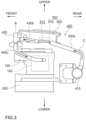
- FIG. 3 is an explanatory view schematically illustrating part of the internal configuration of the outboard motor main body 110.
- FIG. 4 is an explanatory view illustrating a configuration of a coolant flow path 400.
- FIGS. 3 and 4 show the internal structure housed within the waterproof case 112.
- the outboard motor 100 includes the coolant flow path 400, which is a series of flow paths through which coolant liquid C circulates.
- the coolant liquid C circulates inside the outboard motor main body 110 to cool the electric motor 122 and the MCU 510 described below.
- the coolant liquid C is an antifreeze solution mainly composed of e.g., ethylene glycol or propylene glycol.
- the coolant liquid C is an example of the coolant.
- the control assembly 500 includes a control case 502, a motor control unit (MCU) 510, and a power supply line 520 (see FIG. 2 ).
- the MCU 510 is a circuit board that controls the rotation of the electric motor 122 and the like.
- the control case 502 houses the MCU 510. Inside the control case 502, there is a space 512 that is a flow path for the coolant liquid C. In other words, the coolant flow path 400 includes the space 512 formed inside the control case 502.
- the power supply line 520 supplies power to the MCU 510 from a battery or the like (not shown) installed in the hull 200.
- the MCU 510 is an example of the motor control device.
- the outboard motor 100 further includes a motor cooling device 126, an air vent 420, a filler 450, a heat exchanger 440, a pump 410, and multiple coolant tubes 430a to 430f.
- the motor cooling device 126 has a ring-shaped configuration when viewed in the upper-lower direction and is arranged to surround the outer circumference of the electric motor 122. Inside the motor cooling device 126, a space is formed that is a flow path for the coolant liquid C. In other words, the coolant flow path 400 includes the space formed inside the motor cooling device 126.
- the air vent 420 includes an opening for releasing air that has mixed into the coolant flow path 400 to the atmosphere. By removing air from the coolant flow path 400, the air vent 420 improves the cooling efficiency of the electric motor 122 and the MCU 510.
- the air vent 420 is located at an uppermost portion of the coolant flow path 400.
- the filler 450 includes an opening that functions as a filling port for the coolant liquid C in the coolant flow path 400.
- the opening of the filler 450 also has a function for releasing air that has mixed into the coolant flow path 400 to the atmosphere.
- the filler 450 is located at a relatively higher position in the coolant flow path 400, and more specifically, it is located at a position higher than the electric motor 122 and the motor cooling device 126.
- the heat exchanger 440 is a device in which heat exchange occurs between the coolant liquid C and seawater that is pumped up from outside the outboard motor 100 by a pump (not shown).
- the coolant liquid C becomes relatively hot as it passes near the electric motor 122 and the MCU 510 and is cooled by exchanging heat with seawater in the heat exchanger 440.
- the pump 410 is a device that pumps the coolant liquid C.
- the pump 410 is connected to the coolant tube 430a described below and the coolant tube 430f described below.
- the coolant liquid C circulates through the coolant flow path 400 by the operation of the pump 410.
- the pump 410 is located at a relatively lower position in the coolant flow path 400, and more specifically, it is located at a height lower than the MCU 510 and the control case 502.
- the multiple coolant tubes 430a to 430f are tubular members that are hollow from one end to the other end, and the space formed inside each of them forms at least a part of the coolant flow path 400.
- Each of the coolant tubes 430a to 430f is configured such that the coolant liquid C flows from one end to the other end by the operation of the pump 410.
- the coolant tube 430a forms a portion of the coolant flow path 400 that extends from the pump 410 to the control case 502.
- One end of the coolant tube 430a is connected to the pump 410 to communicate with the flow path of the coolant liquid C formed in the pump 410.
- the other end of the coolant tube 430a is connected to the control case 502 to communicate with the space 512 of the control case 502.
- the coolant tube 430b forms a portion of the coolant flow path 400 that extends from the control case 502 to the air vent 420.
- One end of the coolant tube 430b is connected to the control case 502 to communicate with the space 512 of the control case 502.
- the other end of the coolant tube 430b is connected to the end of one end of the coolant tube 430c to communicate with the coolant tube 430c.
- the lower end of the coolant tube 430b (the lowest portion in the coolant tube 430b) is the connection position with the control case 502.
- the coolant tube 430b is an example of the first coolant tube.
- the coolant tube 430c forms a portion of the coolant flow path 400 that extends from the air vent 420 to the motor cooling device 126.
- One end of the coolant tube 430c is connected to the air vent 420.
- the other end of the coolant tube 430c is connected to the motor cooling device 126 to communicate with the space formed inside the motor cooling device 126.
- the coolant tube 430d forms a portion of the coolant flow path 400 that extends from the motor cooling device 126 to the filler 450.
- One end of the coolant tube 430d is connected to the motor cooling device 126 to communicate with the space formed inside the motor cooling device 126.
- the other end of the coolant tube 430d is connected to the end of one end of the coolant tube 430e to communicate with the coolant tube 430e.
- the lower end of the coolant tube 430d (the lowest portion in the coolant tube 430d) is the connection position with the motor cooling device 126.
- the coolant tube 430d is an exam ple of the second coolant tube.
- the coolant tube 430e forms a portion of the coolant flow path 400 that extends from the filler 450 to the heat exchanger 440.
- One end of the coolant tube 430e is connected to the filler 450.
- the other end of the coolant tube 430e is connected to the heat exchanger 440 to communicate with the flow path of the coolant liquid C formed in the heat exchanger 440.
- the coolant tube 430f forms a portion of the coolant flow path 400 that extends from the heat exchanger 440 to the pump 410.
- One end of the coolant tube 430f is connected to the heat exchanger 440 to communicate with the flow path of the coolant liquid C formed in the heat exchanger 440.
- the other end of the coolant tube 430f is connected to the pump 410 to communicate with the flow path of the coolant liquid C formed in the pump 410.
- the coolant flow path 400 is configured such that the coolant liquid C pumped by the pump 410 flows in the order of the MCU 510, the air vent 420, the motor cooling device 126, the filler 450, and the heat exchanger 440, and then circulates back to the pump 410.
- the coolant liquid C flows out of the pump 410, passes through the coolant tube 430a, and flows into space 512.
- the coolant liquid C that flows into space 512 flows near the MCU 510 to cool the MCU 510.
- the coolant liquid C flows out of the space 512, passes through the coolant tube 430b, and flows into the coolant tube 430c to flow near the air vent 420. If air has been mixed into the coolant liquid C at this time, the air flows towards the air vent 420, which is located at a position higher than the connection position between the coolant tubes 430b, 430c and is released to the atmosphere via the air vent 420 (arrow A in FIGS. 3 and 4 ).
- the coolant liquid C passes through the coolant tube 430c and flows into the space formed inside the motor cooling device 126.
- the coolant liquid C that flows into the space formed inside the motor cooling device 126 flows near the electric motor 122 to cool the electric motor 122.
- the coolant liquid C flows out of the space formed inside the motor cooling device 126, passes through the coolant tube 430d, and flows into the coolant tube 430e to flow near the filler 450. If air has been mixed into the coolant liquid C at this time, the air flows towards the filler 450, which is located at a position higher than the connection position between the coolant tubes 430d and 430e, and is released to the atmosphere via the filler 450 (arrow A in FIGS. 3 and 4 ).
- the coolant liquid C passes through the coolant tube 430e and flows into the heat exchanger 440.
- the coolant liquid C is cooled by exchanging heat with seawater pumped in from outside the outboard motor 100.
- the coolant liquid C flows out of the heat exchanger 440, passes through the coolant tube 430f, and flows into the pump 410.
- the coolant liquid C circulates through the coolant flow path 400.
- FIG. 5 is an explanatory view illustrating a detailed configuration of the pump 410.
- the pump 410 is formed with a suction port 412 and a discharge port 414.
- the suction port 412 is the part connected to the coolant tube 430f and is the part into which the coolant liquid C flows from the outside of the pump 410.
- the suction port 412 is formed near the center of the pump 410 in the upper-lower direction.
- the discharge port 414 is the part connected to the coolant tube 430a and is the part from which the coolant liquid C flows out towards the outside of the pump 410.
- the discharge port 414 is formed at a substantially uppermost portion of the pump 410.
- the present embodiment of the outboard motor 100 includes the drive source, the MCU 510, the multiple coolant tubes 430a to 430f, the pump 410, and the air vent 420.
- the drive source includes the electric motor 122.
- the MCU 510 is arranged at a position higher than the electric motor 122 and controls the electric motor 122.
- the coolant tubes 430a to 430f form at least a part of the coolant flow path 400 through which the coolant liquid C circulates to cool the electric motor 122 and the MCU 510.
- the pump 410 is connected to the coolant tubes 430a and 430f to pump the coolant liquid C.
- the air vent 420 is located at an uppermost portion of the coolant flow path 400.
- the coolant flow path 400 is configured such that the coolant liquid C pumped by the pump 410 flows in the order of the MCU 510, the air vent 420, and the electric motor 122.
- the present outboard motor 100 of this embodiment e.g., when filling the coolant flow path 400 with the coolant liquid C, if air also enters the coolant flow path 400, the air pumped by the pump 410 along with the coolant liquid C will pass through the MCU 510 to reach the air vent 420 located at the uppermost portion of the coolant flow path 400.
- This makes it less likely for air to be trapped near the MCU 510, which is one of the devices that constitute the outboard motor 100 and tends to become relatively hot, thereby improving the cooling efficiency of the outboard motor 100.
- the durability of each device that constitutes the outboard motor 100 is improved, and this in turn improves the durability of the outboard motor 100.
- the pump 410 is arranged at a position lower than the MCU 510.
- the air pumped by the pump 410 along with the coolant liquid C will pass through the MCU 510, which is located at a position higher than the pump 410 to reach the air vent 420, which is located at an uppermost portion of the coolant flow path 400. This makes it less likely for air to be trapped in the section from the pump 410 to the air vent 420, thereby more effectively improving the cooling efficiency of the outboard motor 100.
- the outboard motor 100 of this embodiment further includes the control case 502 that houses the MCU 510, the coolant flow path 400 includes the space 512 formed inside the control case 502, the multiple coolant tubes 430a to 430f include the coolant tube 430b that is connected to the control case 502 and forms a part of the coolant flow path 400 that extends from the control case 502 to the air vent 420, and the lower end of the coolant tube 430b is the connection position with the control case 502.
- the air pumped by the pump 410 along with the coolant liquid C will pass through the control case 502, enter into the coolant tube 430b, and flow from the connection position with the control case 502, which is the lower end of the coolant tube 430b, towards the air vent 420.
- the outboard motor 100 of this embodiment further includes the filler 450 that is a filling port for the coolant liquid C in the coolant flow path 400 and is located at a position higher than the electric motor 122, the coolant flow path 400 is configured such that the coolant liquid C pumped by the pump 410 flows in the order of the MCU 510, the air vent 420, the electric motor 122, and the filler 450.
- the air pumped by the pump 410 along with the coolant liquid C will pass through the electric motor 122 to reach the filler 450, which is located at a position higher than the electric motor 122. This makes it less likely for air to be trapped near the electric motor 122, which is one of the devices that constitute the outboard motor 100 and tends to become relatively hot, thereby more effectively improving the cooling efficiency of the outboard motor 100.
- the outboard motor 100 further includes the motor cooling device 126 arranged to surround the outer circumference of the electric motor 122, the coolant flow path 400 includes a space formed inside the motor cooling device 126, the multiple coolant tubes 430a to 430f includes the coolant tube 430d that is connected to the motor cooling device 126 and forms a part of the coolant flow path 400 that extends from the motor cooling device 126 to the filler 450, and the lower end of the coolant tube 430d is the connection position with the motor cooling device 126.
- the air pumped by the pump 410 along with the coolant liquid C will pass through the motor cooling device 126, enter into the coolant tube 430d, and flow from the connection position with the motor cooling device 126, which is the lower end of the coolant tube 430d, towards the filler 450.
- the discharge port 414 of the pump 410 is formed at a substantially uppermost portion of the pump 410. According to the present outboard motor 100 of this embodiment, since the discharge port 414 of the pump 410 is formed at a substantially uppermost portion of the pump 410, it is less likely for air to be trapped inside the pump 410, thereby more effectively improving the cooling efficiency of the outboard motor 100.
- the configuration of the boat 10 and the outboard motor 100 of the preferred embodiment is an example and may be variously modified.
- the drive source of the above embodiment only includes the electric motor 122.
- the drive source may include both the electric motor and an engine such as an internal combustion engine.
- the MCU 510 is arranged at a position higher than the electric motor 122.
- the MCU may be arranged at a position lower than the electric motor.
- coolant tubes 430a to 430f there are multiple coolant tubes 430a to 430f. Alternatively, only one coolant tube may be provided.
- the pump 410 is arranged at a position lower than the MCU 510.
- the pump may be arranged at a position higher than the MCU.
- the space 512 is formed in the control case 502, and the MCU 510 is cooled by the coolant liquid C flowing into the space 512.
- the coolant tube may be arranged near the MCU, and the MCU may be cooled by the coolant liquid flowing through the coolant tube.
- a space is formed inside the motor cooling device 126, and the electric motor 122 is cooled by the coolant liquid C flowing into the space inside the motor cooling device 126.
- the coolant tube may be arranged near the electric motor, and the electric motor may be cooled by the coolant fluid flowing through the coolant tube.
- the lower end of the coolant tube 430b is the connection position with the control case 502. Alternatively, another connection position may be selected. Similarly, in the above embodiment, the lower end of the coolant tube 430d is the connection position with the motor cooling device 126. Alternatively, another connection position may be selected.
- the discharge port 414 of the pump 410 is formed at a substantially uppermost portion. Alternatively, another portion may be selected.
- coolant liquid C (antifreeze mainly composed of ethylene glycol or propylene glycol) is shown as an example coolant.
- another type of coolant may be selected as long as it cools the electric motor and motor control device.
- the motor control device is exemplified by the MCU 510.
- another motor control device such as an inverter may be selected.
Landscapes
- Engineering & Computer Science (AREA)
- Chemical & Material Sciences (AREA)
- Combustion & Propulsion (AREA)
- Mechanical Engineering (AREA)
- Ocean & Marine Engineering (AREA)
- Power Engineering (AREA)
- Motor Or Generator Cooling System (AREA)
Abstract
Description
- The present invention relates to an outboard motor and a boat.
- A boat includes a hull and an outboard motor mounted to a rear portion of the hull. The outboard motor is a device that generates thrust to propel the boat.
- An outboard motor has been disclosed that includes an electric motor as a drive source, an inverter that controls the drive of the electric motor, a cooling water pipe that forms at least a part of a cooling water flow path through which cooling water circulates to cool the electric motor and inverter, and a pump connected to the cooling water pipe to circulate the cooling water (see, e.g.,
JP 2022-34677 A - In an outboard motor that includes an electric motor as a drive source, it is desired to improve the cooling efficiency of each device that forms the outboard motor in order to improve the durability of the outboard motor.
- It is the object of the present invention to provide an outboard motor having high cooling efficiency and high durability of the outboard motor.
- According to the present invention said object is solved by an outboard motor having the features of independent claim 1. Preferred embodiments are laid down in the dependent claims.
- Accordingly, the technology disclosed herein can be implemented in the following aspects.
- An outboard motor disclosed herein includes a drive source, a motor control device, one or multiple coolant tubes, a pump, and an air vent. The drive source includes an electric motor. The motor control device is arranged at a position higher than the electric motor and controls the electric motor. The coolant tube forms at least a part of a coolant flow path through which coolant that cools the electric motor and the motor control device circulates. The pump is connected to the coolant tube to pump the coolant. The air vent is located at an uppermost portion of the coolant flow path. The coolant flow path is configured such that the coolant pumped by the pump flows in the order of the motor control device, the air vent, and the electric motor.
- In this outboard motor, e.g., when filling the coolant flow path with the coolant, if air also enters the coolant flow path, the air pumped by the pump along with the coolant will pass through the motor control device to reach the air vent located at the uppermost portion of the coolant flow path. This makes it less likely for air to be trapped near the motor control device, which is one of the devices that constitute the outboard motor and tends to become relatively hot, thereby improving the cooling efficiency of the outboard motor.
- The outboard motor may be configured such that the pump is arranged at a position lower than the motor control device. According to this configuration, e.g., when filling the coolant flow path with the coolant, if air also enters the coolant flow path, the air pumped by the pump along with the coolant will pass through the motor control device, which is located at a position higher than the pump, to reach the air vent, which is located at an uppermost portion of the coolant flow path. This makes it less likely for air to be trapped in the section from the pump to the air vent, thereby more effectively improving the cooling efficiency of the outboard motor.
- The outboard motor may be configured to further include a control case that houses the motor control device, wherein the coolant flow path includes a space formed inside the control case, the multiple coolant tubes include a first coolant tube that is connected to the control case and forms a part of the coolant flow path that extends from the control case to the air vent, and the lower end of the first coolant tube is the connection position with the control case. According to this configuration, e.g., when filling the coolant flow path with the coolant, if air also enters the coolant flow path, the air pumped by the pump along with the coolant will pass through the control case, enter into the first coolant tube, and flow from the connection position with the control case, which is the lower end of the first coolant tube, towards the air vent. This makes it less likely for air to be trapped in the section from the pump to the air vent, thereby more effectively improving the cooling efficiency of the outboard motor.
- The outboard motor may be configured to include a filler that is a filling port for the coolant in the coolant flow path and is located at a position higher than the electric motor, wherein the coolant flow path is configured such that the coolant pumped by the pump flows in the order of the motor control device, the air vent, the electric motor, and the filler. According to this configuration, e.g., when filling the coolant flow path with the coolant, if air also enters the coolant flow path, the air pumped by the pump along with the coolant will pass through the electric motor to reach the filler, which is located at a position higher than the electric motor. This makes it less likely for air to be trapped near the electric motor, which is one of the devices that constitute the outboard motor and tends to become relatively hot, thereby more effectively improving the cooling efficiency of the outboard motor.
- The outboard motor may be configured to include a motor cooling device arranged to surround the outer circumference of the electric motor, wherein the coolant flow path includes a space formed inside the motor cooling device, the multiple coolant tubes includes a second coolant tube that is connected to the motor cooling device and forms a part of the coolant flow path that extends from the motor cooling device to the filler, and the lower end of the second coolant tube is the connection position with the motor cooling device. According to this configuration, e.g., when filling the coolant flow path with the coolant, if air also enters the coolant flow path, the air pumped by the pump along with the coolant will pass through the motor cooling device, enter into the second coolant tube, and flow from the connection position with the motor cooling device, which is the lower end of the second coolant tube, towards the filler. This makes it less likely for air to be trapped in the section from the motor cooling device to the filler, thereby more effectively improving the cooling efficiency of the outboard motor.
- The outboard motor may be configured such that the outlet of the pump is formed at a substantially uppermost portion of the pump. According to this configuration, since the outlet of the pump is formed at a substantially uppermost portion of the pump, it is less likely for air to be trapped inside the pump, thereby more effectively improving the cooling efficiency of the outboard motor.
- Another outboard motor disclosed herein includes a drive source, a motor control device, one or multiple coolant tubes, a pump, and an air vent. The drive source includes an electric motor. The motor control device controls the electric motor. The coolant tube forms at least a part of a coolant flow path through which coolant that cools the electric motor and the motor control device circulates. The pump is connected to the coolant tube to pump the coolant. The air vent is located at an uppermost portion of the coolant flow path. The coolant flow path is configured such that the coolant pumped by the pump flows in the order of the motor control device, the air vent, and the electric motor.
- In this outboard motor, e.g., when filling the coolant flow path with the coolant, if air also enters the coolant flow path, the air pumped by the pump along with the coolant will pass through the motor control device to reach the air vent located at the uppermost portion of the coolant flow path. This makes it less likely for air to be trapped near the motor control device, which is one of the devices that constitute the outboard motor and tends to become relatively hot, thereby improving the cooling efficiency of the outboard motor.
- The technology disclosed herein can be implemented in various aspects, including, e.g., an outboard motor, a boat provided with an outboard motor and a hull, among other forms.
- In this outboard motor, e.g., when filling the coolant flow path with the coolant, if air also enters the coolant flow path, the air pumped by the pump along with the coolant will pass through the motor control device to reach the air vent located at the uppermost portion of the coolant flow path. This makes it less likely for air to be trapped near the motor control device, which is one of the devices that constitute the outboard motor and tends to become relatively hot, thereby improving the cooling efficiency of the outboard motor.
-
-
FIG. 1 is a perspective view schematically illustrating a configuration of a boat of this embodiment. -
FIG. 2 is a side view schematically illustrating a configuration of an outboard motor of this embodiment. -
FIG. 3 is an explanatory view schematically illustrating part of the internal configuration of the outboard motor main body. -
FIG. 4 is an explanatory view illustrating a configuration of a coolant flow path. -
FIG. 5 is an explanatory view illustrating a detailed configuration of a pump. -
FIG. 1 is a perspective view schematically illustrating a configuration of aboat 10 of this embodiment.FIG. 1 and other drawings described below show arrows representing each direction with respect to the position of theboat 10. More specifically, each drawing shows arrows representing the front direction (FRONT), rear direction (REAR), left direction (LEFT), right direction (RIGHT), upper direction (UPPER), and lower direction (LOWER), respectively. The front-rear direction, left-right direction, and upper-lower direction are orthogonal to each other. It should be noted that, in this specification, axes, members, and the like extending in the front-rear direction need not necessarily be parallel to the front-rear direction. Axes and members extending in the front-rear direction include axes and members inclined within the range of ±45° to the front-rear direction. Similarly, axes and members extending in the upper-lower direction include axes and members inclined within a range of ±45° to the upper-lower direction, and axes and members extending in the left-right direction include axes and members inclined within a range of ±45° to the left-right direction. - The
boat 10 includes ahull 200 and anoutboard motor 100. In this embodiment, theboat 10 has only oneoutboard motor 100, but theboat 10 may havemultiple outboard motors 100. - The
hull 200 is a part of theboat 10 for occupants to ride. Thehull 200 includes a hullmain body 202 including aliving space 204, apilot seat 240 installed in theliving space 204, and anoperating device 250 installed near thepilot seat 240. Theoperating device 250 is a device for steering the boat and includes, e.g., asteering wheel 252, a shift/throttle lever 254, ajoystick 255, amonitor 256, and aninput device 258. Thehull 200 includes apartition wall 220 to partition the rear end of theliving space 204 and atransom 210 disposed at the rear end of thehull 200. In the front-rear direction, aspace 206 is provided between thetransom 210 and thepartition wall 220. -
FIG. 2 is a side view schematically illustrating a configuration of anoutboard motor 100 of this embodiment. Theoutboard motor 100 in the reference attitude will be described below unless otherwise specified. The reference attitude is an attitude in which the rotation axis Ac of theoutput shaft 123, which will be described later, extends in the upper-lower direction, and the rotation axis Ap of thepropeller shaft 135, which will be described later, extends in the front-rear direction. The front-rear direction, the left-right direction, and the upper-lower direction are respectively defined based on theoutboard motor 100 in the reference attitude. - The
outboard motor 100 is a device that generates thrust to propel theboat 10. Theoutboard motor 100 is attached to thetransom 210 at a rear portion of thehull 200. Theoutboard motor 100 includes an outboard motormain body 110 and asuspension device 150. - The outboard motor
main body 110 includes awaterproof case 112, amiddle case 116, alower case 118, amotor assembly 120, acontrol assembly 500, atransmission mechanism 130, apropeller 111, and asteering mechanism 140. - The
waterproof case 112 is a housing located at an upper portion of the outboard motormain body 110. Thewaterproof case 112 houses anelectric motor 122 described below and other electrical components to protect theelectric motor 122 and electrical components from being exposed to seawater. Thewaterproof case 112 includes anupper cover 113 constituting the upper part of thewaterproof case 112 and alower box 114 constituting the lower part of thewaterproof case 112. Thelower box 114 has a box-shaped configuration with an open top. Theupper cover 113 is removably attached to thelower box 114 so as to cover the open top of thelower box 114. - The
middle case 116 is a housing located below thewaterproof case 112 and arranged near the center of the outboard motormain body 110 in the upper-lower direction. The upper part of themiddle case 116 is connected to thelower box 114 of thewaterproof case 112. - The
lower case 118 is a housing located below themiddle case 116 and arranged at the bottom of the outboard motormain body 110. - The
motor assembly 120 is housed inside thewaterproof case 112. Themotor assembly 120 includes anelectric motor 122 as a driving source. Theelectric motor 122 is a prime mover that generates power. Theelectric motor 122 has anoutput shaft 123 that outputs the driving force generated by theelectric motor 122. Theoutput shaft 123 is arranged in an attitude in which its rotation axis Ac extends in the upper-lower direction. - The
control assembly 500 is housed inside thewaterproof case 112 and is arranged at a position higher than themotor assembly 120. Thecontrol assembly 500 controls the rotation of theelectric motor 122 and the like. The detailed structure of thecontrol assembly 500 is described later. - The
transmission mechanism 130 transmits the driving force of theelectric motor 122 to thepropeller 111. Thetransmission mechanism 130 includes aprimary reduction gear 300, adrive shaft 133, and apropeller shaft 135. - The
primary reduction gear 300 is housed inside thewaterproof case 112 and is arranged at a position lower than themotor assembly 120. Theprimary reduction gear 300 is connected to theoutput shaft 123 of theelectric motor 122 and thedrive shaft 133. Theprimary reduction gear 300 reduces the driving force of theelectric motor 122 and transmits it to thedrive shaft 133. This allows thepropeller 111 to rotate at a desired torque. - The
drive shaft 133 is a rod-shaped member that transmits power to thepropeller shaft 135 and is arranged in an attitude extending in the upper-lower direction. Thedrive shaft 133 is housed so that it spans the inside of thewaterproof case 112, the inside of themiddle case 116, and the inside of thelower case 118. - The
propeller shaft 135 is a rod-shaped member that is arranged in an attitude extending in the front-rear direction at a height relatively lower than the outboard motormain body 110. Thepropeller shaft 135 rotates together with thepropeller 111. The front end of thepropeller shaft 135 is housed in thelower case 118, and the rear end of thepropeller shaft 135 protrudes rearward from thelower case 118. - A gear is provided at the lower end of the
drive shaft 133 and at the front end of thepropeller shaft 135, respectively. The rotation of thedrive shaft 133 is transmitted to thepropeller shaft 135 by meshing the gears of thedrive shaft 133 and thepropeller shaft 135. - The
propeller 111 is a rotating member with multiple blades and is attached to the rear end of thepropeller shaft 135. Thepropeller 111 rotates along with the rotation of thepropeller shaft 135 about the rotation axis Ap. Thepropeller 111 generates thrust to propel theboat 10 by rotating. - The
steering mechanism 140 is a mechanism that controls changes in the traveling direction of theboat 10. Thesteering mechanism 140 has asteering shaft 141. The steeringshaft 141 is a hollow tubular member arranged to surround the outer circumference of thedrive shaft 133. At least a part of thesteering shaft 141 is housed in themiddle case 116 and is supported so as to be rotatable about the rotation axis As. The lower portion of thesteering shaft 141 protrudes downward from themiddle case 116 and is connected to thelower case 118. The steeringshaft 141 rotates about the rotation axis As, for example, by the driving force of the drive motor (not shown) housed in themiddle case 116. When thesteering shaft 141 rotates, thelower case 118 connected to thesteering shaft 141 also rotates, and the direction of thepropeller 111 is changed. This changes the direction of the thrust generated by thepropeller 111 to enable the steering of theboat 10. - The
suspension device 150 is a device to suspend the outboard motormain body 110 to thehull 200. Thesuspension device 150 includes a pair of left andright clamp brackets 152, atilt shaft 154, and aswivel bracket 156. - The pair of left and
right clamp brackets 152 are disposed behind thehull 200 in a state separated from each other in the left-right direction and are fixed to thetransom 210 of thehull 200 by using, e.g., bolts. - The
tilt shaft 154 is a rod-shaped member and is rotatably supported by theclamp brackets 152. The tilt axis At, which is the center line of thetilt shaft 154, constitutes the horizontal (left-right) axis of theoutboard motor 100 during tilting. - The
swivel bracket 156 is disposed so as to be sandwiched between the pair ofclamp brackets 152 and is supported by theclamp brackets 152 via thetilt shaft 154 so as to be rotatable about the tilt axis At. Theswivel bracket 156 is driven to rotate about the tilt axis At relative to theclamp bracket 152 by a tilting device (not shown) that includes an actuator such as a hydraulic cylinder. - When the
swivel bracket 156 rotates about the tilt axis At with respect to theclamp bracket 152, the outboard motormain body 110 supported by theswivel bracket 156 also rotates about the tilt axis At. This achieves the tilting operation of rotating the outboard motormain body 110 in the upper-lower direction with respect to thehull 200. By this tilting operation, theoutboard motor 100 can change the angle of the outboard motormain body 110 about the tilt axis At in the range from the tilt-down state in which thepropeller 111 is disposed under the water (the state in which theoutboard motor 100 is in the reference attitude) to the tilt-up state in which thepropeller 111 is disposed above the water surface. Trimming operation for adjusting the attitude of theboat 10 during travel can also be performed by adjusting the angle about the tilt axis At of the outboard motormain body 110. -
FIG. 3 is an explanatory view schematically illustrating part of the internal configuration of the outboard motormain body 110.FIG. 4 is an explanatory view illustrating a configuration of acoolant flow path 400.FIGS. 3 and4 show the internal structure housed within thewaterproof case 112. As shown inFIGS. 3 and4 , theoutboard motor 100 includes thecoolant flow path 400, which is a series of flow paths through which coolant liquid C circulates. - The coolant liquid C circulates inside the outboard motor
main body 110 to cool theelectric motor 122 and theMCU 510 described below. The coolant liquid C is an antifreeze solution mainly composed of e.g., ethylene glycol or propylene glycol. The coolant liquid C is an example of the coolant. - As shown in
FIG. 3 , thecontrol assembly 500 includes acontrol case 502, a motor control unit (MCU) 510, and a power supply line 520 (seeFIG. 2 ). TheMCU 510 is a circuit board that controls the rotation of theelectric motor 122 and the like. Thecontrol case 502 houses theMCU 510. Inside thecontrol case 502, there is aspace 512 that is a flow path for the coolant liquid C. In other words, thecoolant flow path 400 includes thespace 512 formed inside thecontrol case 502. Thepower supply line 520 supplies power to theMCU 510 from a battery or the like (not shown) installed in thehull 200. TheMCU 510 is an example of the motor control device. - As shown in
FIG. 4 , theoutboard motor 100 further includes amotor cooling device 126, anair vent 420, afiller 450, aheat exchanger 440, apump 410, andmultiple coolant tubes 430a to 430f. - The
motor cooling device 126 has a ring-shaped configuration when viewed in the upper-lower direction and is arranged to surround the outer circumference of theelectric motor 122. Inside themotor cooling device 126, a space is formed that is a flow path for the coolant liquid C. In other words, thecoolant flow path 400 includes the space formed inside themotor cooling device 126. - The
air vent 420 includes an opening for releasing air that has mixed into thecoolant flow path 400 to the atmosphere. By removing air from thecoolant flow path 400, theair vent 420 improves the cooling efficiency of theelectric motor 122 and theMCU 510. Theair vent 420 is located at an uppermost portion of thecoolant flow path 400. - The
filler 450 includes an opening that functions as a filling port for the coolant liquid C in thecoolant flow path 400. The opening of thefiller 450 also has a function for releasing air that has mixed into thecoolant flow path 400 to the atmosphere. Thefiller 450 is located at a relatively higher position in thecoolant flow path 400, and more specifically, it is located at a position higher than theelectric motor 122 and themotor cooling device 126. - The
heat exchanger 440 is a device in which heat exchange occurs between the coolant liquid C and seawater that is pumped up from outside theoutboard motor 100 by a pump (not shown). The coolant liquid C becomes relatively hot as it passes near theelectric motor 122 and theMCU 510 and is cooled by exchanging heat with seawater in theheat exchanger 440. - The
pump 410 is a device that pumps the coolant liquid C. Thepump 410 is connected to thecoolant tube 430a described below and thecoolant tube 430f described below. The coolant liquid C circulates through thecoolant flow path 400 by the operation of thepump 410. Thepump 410 is located at a relatively lower position in thecoolant flow path 400, and more specifically, it is located at a height lower than theMCU 510 and thecontrol case 502. - The
multiple coolant tubes 430a to 430f are tubular members that are hollow from one end to the other end, and the space formed inside each of them forms at least a part of thecoolant flow path 400. Each of thecoolant tubes 430a to 430f is configured such that the coolant liquid C flows from one end to the other end by the operation of thepump 410. - The
coolant tube 430a forms a portion of thecoolant flow path 400 that extends from thepump 410 to thecontrol case 502. One end of thecoolant tube 430a is connected to thepump 410 to communicate with the flow path of the coolant liquid C formed in thepump 410. The other end of thecoolant tube 430a is connected to thecontrol case 502 to communicate with thespace 512 of thecontrol case 502. - The
coolant tube 430b forms a portion of thecoolant flow path 400 that extends from thecontrol case 502 to theair vent 420. One end of thecoolant tube 430b is connected to thecontrol case 502 to communicate with thespace 512 of thecontrol case 502. In addition, the other end of thecoolant tube 430b is connected to the end of one end of thecoolant tube 430c to communicate with thecoolant tube 430c. In addition, the lower end of thecoolant tube 430b (the lowest portion in thecoolant tube 430b) is the connection position with thecontrol case 502. Thecoolant tube 430b is an example of the first coolant tube. - The
coolant tube 430c forms a portion of thecoolant flow path 400 that extends from theair vent 420 to themotor cooling device 126. One end of thecoolant tube 430c is connected to theair vent 420. The other end of thecoolant tube 430c is connected to themotor cooling device 126 to communicate with the space formed inside themotor cooling device 126. - The
coolant tube 430d forms a portion of thecoolant flow path 400 that extends from themotor cooling device 126 to thefiller 450. One end of thecoolant tube 430d is connected to themotor cooling device 126 to communicate with the space formed inside themotor cooling device 126. In addition, the other end of thecoolant tube 430d is connected to the end of one end of thecoolant tube 430e to communicate with thecoolant tube 430e. The lower end of thecoolant tube 430d (the lowest portion in thecoolant tube 430d) is the connection position with themotor cooling device 126. Thecoolant tube 430d is an exam ple of the second coolant tube. - The
coolant tube 430e forms a portion of thecoolant flow path 400 that extends from thefiller 450 to theheat exchanger 440. One end of thecoolant tube 430e is connected to thefiller 450. The other end of thecoolant tube 430e is connected to theheat exchanger 440 to communicate with the flow path of the coolant liquid C formed in theheat exchanger 440. - The
coolant tube 430f forms a portion of thecoolant flow path 400 that extends from theheat exchanger 440 to thepump 410. One end of thecoolant tube 430f is connected to theheat exchanger 440 to communicate with the flow path of the coolant liquid C formed in theheat exchanger 440. The other end of thecoolant tube 430f is connected to thepump 410 to communicate with the flow path of the coolant liquid C formed in thepump 410. - The
coolant flow path 400 is configured such that the coolant liquid C pumped by thepump 410 flows in the order of theMCU 510, theair vent 420, themotor cooling device 126, thefiller 450, and theheat exchanger 440, and then circulates back to thepump 410. - Specifically, first, the coolant liquid C flows out of the
pump 410, passes through thecoolant tube 430a, and flows intospace 512. The coolant liquid C that flows intospace 512 flows near theMCU 510 to cool theMCU 510. - Next, the coolant liquid C flows out of the
space 512, passes through thecoolant tube 430b, and flows into thecoolant tube 430c to flow near theair vent 420. If air has been mixed into the coolant liquid C at this time, the air flows towards theair vent 420, which is located at a position higher than the connection position between thecoolant tubes FIGS. 3 and4 ). - Next, the coolant liquid C passes through the
coolant tube 430c and flows into the space formed inside themotor cooling device 126. The coolant liquid C that flows into the space formed inside themotor cooling device 126 flows near theelectric motor 122 to cool theelectric motor 122. - Next, the coolant liquid C flows out of the space formed inside the
motor cooling device 126, passes through thecoolant tube 430d, and flows into thecoolant tube 430e to flow near thefiller 450. If air has been mixed into the coolant liquid C at this time, the air flows towards thefiller 450, which is located at a position higher than the connection position between thecoolant tubes FIGS. 3 and4 ). - Next, the coolant liquid C passes through the
coolant tube 430e and flows into theheat exchanger 440. In theheat exchanger 440, the coolant liquid C is cooled by exchanging heat with seawater pumped in from outside theoutboard motor 100. - Next, the coolant liquid C flows out of the
heat exchanger 440, passes through thecoolant tube 430f, and flows into thepump 410. Thus, the coolant liquid C circulates through thecoolant flow path 400. -
FIG. 5 is an explanatory view illustrating a detailed configuration of thepump 410. Thepump 410 is formed with asuction port 412 and adischarge port 414. Thesuction port 412 is the part connected to thecoolant tube 430f and is the part into which the coolant liquid C flows from the outside of thepump 410. Thesuction port 412 is formed near the center of thepump 410 in the upper-lower direction. Thedischarge port 414 is the part connected to thecoolant tube 430a and is the part from which the coolant liquid C flows out towards the outside of thepump 410. Thedischarge port 414 is formed at a substantially uppermost portion of thepump 410. - As explained above, the present embodiment of the
outboard motor 100 includes the drive source, theMCU 510, themultiple coolant tubes 430a to 430f, thepump 410, and theair vent 420. The drive source includes theelectric motor 122. TheMCU 510 is arranged at a position higher than theelectric motor 122 and controls theelectric motor 122. Thecoolant tubes 430a to 430f form at least a part of thecoolant flow path 400 through which the coolant liquid C circulates to cool theelectric motor 122 and theMCU 510. Thepump 410 is connected to thecoolant tubes air vent 420 is located at an uppermost portion of thecoolant flow path 400. Thecoolant flow path 400 is configured such that the coolant liquid C pumped by thepump 410 flows in the order of theMCU 510, theair vent 420, and theelectric motor 122. - According to the present
outboard motor 100 of this embodiment, e.g., when filling thecoolant flow path 400 with the coolant liquid C, if air also enters thecoolant flow path 400, the air pumped by thepump 410 along with the coolant liquid C will pass through theMCU 510 to reach theair vent 420 located at the uppermost portion of thecoolant flow path 400. This makes it less likely for air to be trapped near theMCU 510, which is one of the devices that constitute theoutboard motor 100 and tends to become relatively hot, thereby improving the cooling efficiency of theoutboard motor 100. By improving the cooling efficiency of theoutboard motor 100, the durability of each device that constitutes theoutboard motor 100 is improved, and this in turn improves the durability of theoutboard motor 100. - In addition, in the
outboard motor 100 of this embodiment, thepump 410 is arranged at a position lower than theMCU 510. According to the presentoutboard motor 100 of this embodiment, e.g., when filling thecoolant flow path 400 with the coolant liquid C, if air also enters thecoolant flow path 400, the air pumped by thepump 410 along with the coolant liquid C will pass through theMCU 510, which is located at a position higher than thepump 410 to reach theair vent 420, which is located at an uppermost portion of thecoolant flow path 400. This makes it less likely for air to be trapped in the section from thepump 410 to theair vent 420, thereby more effectively improving the cooling efficiency of theoutboard motor 100. - In addition, the
outboard motor 100 of this embodiment further includes thecontrol case 502 that houses theMCU 510, thecoolant flow path 400 includes thespace 512 formed inside thecontrol case 502, themultiple coolant tubes 430a to 430f include thecoolant tube 430b that is connected to thecontrol case 502 and forms a part of thecoolant flow path 400 that extends from thecontrol case 502 to theair vent 420, and the lower end of thecoolant tube 430b is the connection position with thecontrol case 502. According to the presentoutboard motor 100 of this embodiment, e.g., when filling thecoolant flow path 400 with the coolant liquid C, if air also enters thecoolant flow path 400, the air pumped by thepump 410 along with the coolant liquid C will pass through thecontrol case 502, enter into thecoolant tube 430b, and flow from the connection position with thecontrol case 502, which is the lower end of thecoolant tube 430b, towards theair vent 420. This makes it less likely for air to be trapped in the section from thepump 410 to theair vent 420, thereby more effectively improving the cooling efficiency of theoutboard motor 100. - In addition, the
outboard motor 100 of this embodiment further includes thefiller 450 that is a filling port for the coolant liquid C in thecoolant flow path 400 and is located at a position higher than theelectric motor 122, thecoolant flow path 400 is configured such that the coolant liquid C pumped by thepump 410 flows in the order of theMCU 510, theair vent 420, theelectric motor 122, and thefiller 450. According to the presentoutboard motor 100 of this embodiment, e.g., when filling thecoolant flow path 400 with the coolant liquid C, if air also enters thecoolant flow path 400, the air pumped by thepump 410 along with the coolant liquid C will pass through theelectric motor 122 to reach thefiller 450, which is located at a position higher than theelectric motor 122. This makes it less likely for air to be trapped near theelectric motor 122, which is one of the devices that constitute theoutboard motor 100 and tends to become relatively hot, thereby more effectively improving the cooling efficiency of theoutboard motor 100. - In addition, the
outboard motor 100 further includes themotor cooling device 126 arranged to surround the outer circumference of theelectric motor 122, thecoolant flow path 400 includes a space formed inside themotor cooling device 126, themultiple coolant tubes 430a to 430f includes thecoolant tube 430d that is connected to themotor cooling device 126 and forms a part of thecoolant flow path 400 that extends from themotor cooling device 126 to thefiller 450, and the lower end of thecoolant tube 430d is the connection position with themotor cooling device 126. According to the presentoutboard motor 100 of this embodiment, e.g., when filling thecoolant flow path 400 with the coolant liquid C, if air also enters thecoolant flow path 400, the air pumped by thepump 410 along with the coolant liquid C will pass through themotor cooling device 126, enter into thecoolant tube 430d, and flow from the connection position with themotor cooling device 126, which is the lower end of thecoolant tube 430d, towards thefiller 450. This makes it less likely for air to be trapped in the section from themotor cooling device 126 to thefiller 450, thereby more effectively improving the cooling efficiency of theoutboard motor 100. - In addition, in the
outboard motor 100 of this embodiment, thedischarge port 414 of thepump 410 is formed at a substantially uppermost portion of thepump 410. According to the presentoutboard motor 100 of this embodiment, since thedischarge port 414 of thepump 410 is formed at a substantially uppermost portion of thepump 410, it is less likely for air to be trapped inside thepump 410, thereby more effectively improving the cooling efficiency of theoutboard motor 100. - The configuration of the
boat 10 and theoutboard motor 100 of the preferred embodiment is an example and may be variously modified. For example, the drive source of the above embodiment only includes theelectric motor 122. Alternatively, the drive source may include both the electric motor and an engine such as an internal combustion engine. - In the above embodiment, the
MCU 510 is arranged at a position higher than theelectric motor 122. Alternatively, the MCU may be arranged at a position lower than the electric motor. - In the above embodiment, there are
multiple coolant tubes 430a to 430f. Alternatively, only one coolant tube may be provided. - In the above embodiment, the
pump 410 is arranged at a position lower than theMCU 510. Alternatively, the pump may be arranged at a position higher than the MCU. - In the above embodiment, the
space 512 is formed in thecontrol case 502, and theMCU 510 is cooled by the coolant liquid C flowing into thespace 512. Alternatively, the coolant tube may be arranged near the MCU, and the MCU may be cooled by the coolant liquid flowing through the coolant tube. Similarly, in the above embodiment, a space is formed inside themotor cooling device 126, and theelectric motor 122 is cooled by the coolant liquid C flowing into the space inside themotor cooling device 126. Alternatively, the coolant tube may be arranged near the electric motor, and the electric motor may be cooled by the coolant fluid flowing through the coolant tube. - In the above embodiment, the lower end of the
coolant tube 430b is the connection position with thecontrol case 502. Alternatively, another connection position may be selected. Similarly, in the above embodiment, the lower end of thecoolant tube 430d is the connection position with themotor cooling device 126. Alternatively, another connection position may be selected. - In the above embodiment, the
discharge port 414 of thepump 410 is formed at a substantially uppermost portion. Alternatively, another portion may be selected. - In the above embodiment, coolant liquid C (antifreeze mainly composed of ethylene glycol or propylene glycol) is shown as an example coolant. Alternatively, another type of coolant may be selected as long as it cools the electric motor and motor control device.
- In the above embodiment, the motor control device is exemplified by the
MCU 510. Alternatively, another motor control device such as an inverter may be selected.
Claims (8)
- An outboard motor (100), configured to be attached to a boat (10) in a reference attitude with regard to a front-rear direction of the boat (10), a left-right direction of the boat (10), and an upper-lower direction of the boat (10), the outboard motor (100) comprising:a drive source including an electric motor (122);a motor control device (510) configured to control the electric motor (122);one or multiple coolant tubes (430a to 430f) that form at least a part of a coolant flow path (400) and are configured for a coolant (C) that cools the electric motor (122) andthe motor control device (510) to circulate through;a pump (410) connected to the coolant tube and configured to pump the coolant (C); andan air vent (420) located at an uppermost portion of the coolant flow path (400) with regard to the upper-lower direction of the boat (10), whereinthe coolant flow path (400) is configured such that the coolant (C) pumped by the pump (410) flows in the order of the motor control device (510), the air vent (420),and the electric motor (122).
- The outboard motor (100) according to claim 1, wherein the motor control device (510) is arranged at a position higher than the electric motor (122) with regard to the upper-lower direction of the boat (10).
- The outboard motor (100) according to claim 1 or 2, wherein the pump (410) is arranged at a position lower than the motor control device (510) with regard to the upper-lower direction of the boat (10).
- The outboard motor (100) according to any one of claims 1 to 3, further comprising:a control case (502) that houses the motor control device (510), whereinthe coolant flow path (400) includes a space (512) formed inside the control case (502),the multiple coolant tubes (430a to 430f) includes a first coolant tube (430b) that is connected to the control case (502) and forms a part of the coolant flow path (400) that extends from the control case (502) to the air vent (420), andthe lower end of the first coolant tube (430b), with regard to the upper-lower direction of the boat (10), is a connection position with the control case (502).
- The outboard motor (100) according to any one of claims 1 to 4, further comprising:a filler (450) that is a filling port for the coolant (C) in the coolant flow path (400) and is located at a position higher than the electric motor (122) with regard to the upper-lower direction of the boat (10), whereinthe coolant flow path (400) is configured such that the coolant (C) pumped by the pump (410) flows in the order of the motor control device (510), the air vent (420), the electric motor (122), and the filler (450).
- The outboard motor (100) according to claim 5, further comprising:a motor cooling device (126) arranged to surround an outer circumference of the electric motor (122), whereinthe coolant flow path (400) includes a space formed inside the motor cooling device (126),the multiple coolant tubes (430a to 430f) includes a second coolant tube (430d) that is connected to the motor cooling device (126) and forms a part of the coolant flow path (400) that extends from the motor cooling device (126) to the filler (450), andthe lower end of the second coolant tube (430d), with regard to the upper-lower direction of the boat (10), is a connection position with the motor cooling device (126).
- The outboard motor (100) according to any one of claims 1 to 6, wherein a pump outlet is formed at a substantially uppermost portion of the pump (410) with regard to the upper-lower direction of the boat (10).
- A boat (10), comprising:a hull (200); andthe outboard motor (100) according to any one of claims 1 to 7 mounted to a rear portion of the hull (200) with regard to the front-rear direction of the boat (10) in the reference attitude with regard to the front-rear direction of the boat (10), the left-right direction of the boat (10), and the upper-lower direction of the boat (10).
Applications Claiming Priority (1)
| Application Number | Priority Date | Filing Date | Title |
|---|---|---|---|
| JP2023191229A JP2025078922A (en) | 2023-11-09 | 2023-11-09 | Outboard motors and marine vehicles |
Publications (1)
| Publication Number | Publication Date |
|---|---|
| EP4563459A1 true EP4563459A1 (en) | 2025-06-04 |
Family
ID=93333941
Family Applications (1)
| Application Number | Title | Priority Date | Filing Date |
|---|---|---|---|
| EP24209485.2A Pending EP4563459A1 (en) | 2023-11-09 | 2024-10-29 | Outboard motor and boat |
Country Status (3)
| Country | Link |
|---|---|
| US (1) | US20250153822A1 (en) |
| EP (1) | EP4563459A1 (en) |
| JP (1) | JP2025078922A (en) |
Citations (4)
| Publication number | Priority date | Publication date | Assignee | Title |
|---|---|---|---|---|
| CN201264717Y (en) * | 2008-09-08 | 2009-07-01 | 苏州百胜动力机器有限公司 | Water-cooling electric outboard engine |
| JP2022034677A (en) | 2020-08-19 | 2022-03-04 | スズキ株式会社 | Ship propulsion machine |
| US20230086934A1 (en) * | 2021-09-17 | 2023-03-23 | Suzuki Motor Corporation | Ship propulsion machine and ship propulsion machine set |
| WO2023084244A1 (en) * | 2021-11-11 | 2023-05-19 | Saietta Group PLC | An outboard for watercraft |
-
2023
- 2023-11-09 JP JP2023191229A patent/JP2025078922A/en active Pending
-
2024
- 2024-10-29 EP EP24209485.2A patent/EP4563459A1/en active Pending
- 2024-11-01 US US18/934,523 patent/US20250153822A1/en active Pending
Patent Citations (4)
| Publication number | Priority date | Publication date | Assignee | Title |
|---|---|---|---|---|
| CN201264717Y (en) * | 2008-09-08 | 2009-07-01 | 苏州百胜动力机器有限公司 | Water-cooling electric outboard engine |
| JP2022034677A (en) | 2020-08-19 | 2022-03-04 | スズキ株式会社 | Ship propulsion machine |
| US20230086934A1 (en) * | 2021-09-17 | 2023-03-23 | Suzuki Motor Corporation | Ship propulsion machine and ship propulsion machine set |
| WO2023084244A1 (en) * | 2021-11-11 | 2023-05-19 | Saietta Group PLC | An outboard for watercraft |
Also Published As
| Publication number | Publication date |
|---|---|
| US20250153822A1 (en) | 2025-05-15 |
| JP2025078922A (en) | 2025-05-21 |
Similar Documents
| Publication | Publication Date | Title |
|---|---|---|
| US8333626B2 (en) | Hybrid outboard motor | |
| JP2022034677A (en) | Ship propulsion machine | |
| JP2024065430A (en) | Outboard motors and marine vehicles | |
| JP2023044489A (en) | Hybrid ship propulsion machine | |
| CN114829249A (en) | Marine propulsion unit and marine vessel | |
| EP3934977A1 (en) | A marine outboard motor with drive shaft and cooling system | |
| EP4707159A1 (en) | Electric propulsion device | |
| JP2010221754A (en) | Outboard motor | |
| US20250153822A1 (en) | Outboard motor and boat | |
| US20240359785A1 (en) | Outboard motor and boat | |
| EP4390077B1 (en) | Outboard motor | |
| EP4566937B1 (en) | Outboard motor and boat | |
| EP4454994A1 (en) | Outboard motor and boat | |
| JP2023094184A (en) | Outboard motor | |
| US20240359783A1 (en) | Outboard motor and boat | |
| US20240343371A1 (en) | Outboard motor and boat | |
| KR100300565B1 (en) | Marine drive apparatus | |
| EP4707157A1 (en) | Marine propulsion device | |
| US20240208628A1 (en) | Outboard motor | |
| US20250206432A1 (en) | Boat propulsion device, boat, and movable body | |
| US20240343372A1 (en) | Outboard motor and boat | |
| US12097944B2 (en) | Marine propulsion device | |
| JP2026041187A (en) | electric propulsion machine | |
| JP2023125742A (en) | Outboard engine |
Legal Events
| Date | Code | Title | Description |
|---|---|---|---|
| PUAI | Public reference made under article 153(3) epc to a published international application that has entered the european phase |
Free format text: ORIGINAL CODE: 0009012 |
|
| STAA | Information on the status of an ep patent application or granted ep patent |
Free format text: STATUS: THE APPLICATION HAS BEEN PUBLISHED |
|
| AK | Designated contracting states |
Kind code of ref document: A1 Designated state(s): AL AT BE BG CH CY CZ DE DK EE ES FI FR GB GR HR HU IE IS IT LI LT LU LV MC ME MK MT NL NO PL PT RO RS SE SI SK SM TR |
|
| P01 | Opt-out of the competence of the unified patent court (upc) registered |
Free format text: CASE NUMBER: UPC_APP_2227_4563459/2025 Effective date: 20250801 |
|
| STAA | Information on the status of an ep patent application or granted ep patent |
Free format text: STATUS: REQUEST FOR EXAMINATION WAS MADE |
|
| 17P | Request for examination filed |
Effective date: 20251118 |