EP4563445A1 - Vehicle - Google Patents
Vehicle Download PDFInfo
- Publication number
- EP4563445A1 EP4563445A1 EP23845703.0A EP23845703A EP4563445A1 EP 4563445 A1 EP4563445 A1 EP 4563445A1 EP 23845703 A EP23845703 A EP 23845703A EP 4563445 A1 EP4563445 A1 EP 4563445A1
- Authority
- EP
- European Patent Office
- Prior art keywords
- longitudinal beam
- pillar
- vehicle
- front longitudinal
- cross beam
- Prior art date
- Legal status (The legal status is an assumption and is not a legal conclusion. Google has not performed a legal analysis and makes no representation as to the accuracy of the status listed.)
- Pending
Links
Images

Classifications
-
- B—PERFORMING OPERATIONS; TRANSPORTING
- B62—LAND VEHICLES FOR TRAVELLING OTHERWISE THAN ON RAILS
- B62D—MOTOR VEHICLES; TRAILERS
- B62D25/00—Superstructure or monocoque structure sub-units; Parts or details thereof not otherwise provided for
- B62D25/20—Floors or bottom sub-units
- B62D25/2009—Floors or bottom sub-units in connection with other superstructure subunits
- B62D25/2018—Floors or bottom sub-units in connection with other superstructure subunits the subunits being front structures
-
- B—PERFORMING OPERATIONS; TRANSPORTING
- B62—LAND VEHICLES FOR TRAVELLING OTHERWISE THAN ON RAILS
- B62D—MOTOR VEHICLES; TRAILERS
- B62D21/00—Understructures, i.e. chassis frame on which a vehicle body may be mounted
- B62D21/02—Understructures, i.e. chassis frame on which a vehicle body may be mounted comprising longitudinally or transversely arranged frame members
-
- B—PERFORMING OPERATIONS; TRANSPORTING
- B60—VEHICLES IN GENERAL
- B60K—ARRANGEMENT OR MOUNTING OF PROPULSION UNITS OR OF TRANSMISSIONS IN VEHICLES; ARRANGEMENT OR MOUNTING OF PLURAL DIVERSE PRIME-MOVERS IN VEHICLES; AUXILIARY DRIVES FOR VEHICLES; INSTRUMENTATION OR DASHBOARDS FOR VEHICLES; ARRANGEMENTS IN CONNECTION WITH COOLING, AIR INTAKE, GAS EXHAUST OR FUEL SUPPLY OF PROPULSION UNITS IN VEHICLES
- B60K1/00—Arrangement or mounting of electrical propulsion units
- B60K1/04—Arrangement or mounting of electrical propulsion units of the electric storage means for propulsion
-
- B—PERFORMING OPERATIONS; TRANSPORTING
- B62—LAND VEHICLES FOR TRAVELLING OTHERWISE THAN ON RAILS
- B62D—MOTOR VEHICLES; TRAILERS
- B62D25/00—Superstructure or monocoque structure sub-units; Parts or details thereof not otherwise provided for
- B62D25/04—Door pillars ; windshield pillars
-
- B—PERFORMING OPERATIONS; TRANSPORTING
- B62—LAND VEHICLES FOR TRAVELLING OTHERWISE THAN ON RAILS
- B62D—MOTOR VEHICLES; TRAILERS
- B62D25/00—Superstructure or monocoque structure sub-units; Parts or details thereof not otherwise provided for
- B62D25/08—Front or rear portions
- B62D25/082—Engine compartments
-
- B—PERFORMING OPERATIONS; TRANSPORTING
- B62—LAND VEHICLES FOR TRAVELLING OTHERWISE THAN ON RAILS
- B62D—MOTOR VEHICLES; TRAILERS
- B62D25/00—Superstructure or monocoque structure sub-units; Parts or details thereof not otherwise provided for
- B62D25/08—Front or rear portions
- B62D25/14—Dashboards as superstructure sub-units
- B62D25/145—Dashboards as superstructure sub-units having a crossbeam incorporated therein
-
- B—PERFORMING OPERATIONS; TRANSPORTING
- B62—LAND VEHICLES FOR TRAVELLING OTHERWISE THAN ON RAILS
- B62D—MOTOR VEHICLES; TRAILERS
- B62D25/00—Superstructure or monocoque structure sub-units; Parts or details thereof not otherwise provided for
- B62D25/20—Floors or bottom sub-units
- B62D25/2009—Floors or bottom sub-units in connection with other superstructure subunits
-
- B—PERFORMING OPERATIONS; TRANSPORTING
- B62—LAND VEHICLES FOR TRAVELLING OTHERWISE THAN ON RAILS
- B62D—MOTOR VEHICLES; TRAILERS
- B62D25/00—Superstructure or monocoque structure sub-units; Parts or details thereof not otherwise provided for
- B62D25/20—Floors or bottom sub-units
- B62D25/2009—Floors or bottom sub-units in connection with other superstructure subunits
- B62D25/2027—Floors or bottom sub-units in connection with other superstructure subunits the subunits being rear structures
-
- B—PERFORMING OPERATIONS; TRANSPORTING
- B62—LAND VEHICLES FOR TRAVELLING OTHERWISE THAN ON RAILS
- B62D—MOTOR VEHICLES; TRAILERS
- B62D25/00—Superstructure or monocoque structure sub-units; Parts or details thereof not otherwise provided for
- B62D25/20—Floors or bottom sub-units
- B62D25/2009—Floors or bottom sub-units in connection with other superstructure subunits
- B62D25/2036—Floors or bottom sub-units in connection with other superstructure subunits the subunits being side panels, sills or pillars
-
- B—PERFORMING OPERATIONS; TRANSPORTING
- B62—LAND VEHICLES FOR TRAVELLING OTHERWISE THAN ON RAILS
- B62D—MOTOR VEHICLES; TRAILERS
- B62D25/00—Superstructure or monocoque structure sub-units; Parts or details thereof not otherwise provided for
- B62D25/20—Floors or bottom sub-units
- B62D25/2009—Floors or bottom sub-units in connection with other superstructure subunits
- B62D25/2045—Floors or bottom sub-units in connection with other superstructure subunits the subunits being fire walls
-
- B—PERFORMING OPERATIONS; TRANSPORTING
- B60—VEHICLES IN GENERAL
- B60K—ARRANGEMENT OR MOUNTING OF PROPULSION UNITS OR OF TRANSMISSIONS IN VEHICLES; ARRANGEMENT OR MOUNTING OF PLURAL DIVERSE PRIME-MOVERS IN VEHICLES; AUXILIARY DRIVES FOR VEHICLES; INSTRUMENTATION OR DASHBOARDS FOR VEHICLES; ARRANGEMENTS IN CONNECTION WITH COOLING, AIR INTAKE, GAS EXHAUST OR FUEL SUPPLY OF PROPULSION UNITS IN VEHICLES
- B60K1/00—Arrangement or mounting of electrical propulsion units
- B60K1/04—Arrangement or mounting of electrical propulsion units of the electric storage means for propulsion
- B60K2001/0405—Arrangement or mounting of electrical propulsion units of the electric storage means for propulsion characterised by their position
- B60K2001/0438—Arrangement under the floor
-
- B—PERFORMING OPERATIONS; TRANSPORTING
- B62—LAND VEHICLES FOR TRAVELLING OTHERWISE THAN ON RAILS
- B62D—MOTOR VEHICLES; TRAILERS
- B62D25/00—Superstructure or monocoque structure sub-units; Parts or details thereof not otherwise provided for
- B62D25/08—Front or rear portions
- B62D25/081—Cowls
Definitions
- the present disclosure relates to the technical field of electric vehicles, and more specifically, to a vehicle.
- the battery pack is usually arranged underneath the vehicle.
- the battery pack is connected to a vehicle body assembly on two sides in a width direction through connection points arranged on two sides.
- the battery pack is connected to the vehicle body assembly only in the width direction of the vehicle body assembly, causing the battery pack to be unable to effectively improve torsional performance of the vehicle body.
- the present disclosure is intended to resolve one of technical problems in the related art at least to some extent.
- the present disclosure provides a vehicle.
- the vehicle according to the present disclosure includes a left front longitudinal beam, a right front longitudinal beam, a left A-pillar, a right A-pillar, a windshield upper cross beam, and a battery pack.
- the left front longitudinal beam and the right front longitudinal beam are arranged spaced apart in a width direction of the vehicle.
- the left A-pillar and the right A-pillar are arranged spaced apart in the width direction of the vehicle.
- the left front longitudinal beam is connected to a lower section of the left A-pillar.
- the right front longitudinal beam is connected to a lower section of the right A-pillar.
- Two ends of the windshield upper cross beam are respectively connected to an upper section of the left A-pillar and an upper section of the right A-pillar.
- a front end of the battery pack is directly connected to the left front longitudinal beam and the right front longitudinal beam respectively.
- the left front longitudinal beam, the right front longitudinal beam, the left A-pillar, the right A-pillar, the windshield upper cross beam, and the battery pack form a first A-pillar annular force transmission structure.
- the front end of the battery pack is directly connected to the left front longitudinal beam and the right front longitudinal beam respectively, to cause the left front longitudinal beam, the battery pack, the right front longitudinal beam, the right A-pillar, the windshield upper cross beam, and the left A-pillar to form the first A-pillar annular force transmission structure in front of a passenger compartment and upper front of the battery pack. Therefore, the battery pack is used as a part of the first A-pillar annular force transmission structure, which can effectively enhance strength of the first A-pillar annular force transmission structure, improve torsional resistance thereof, and improve torsional strength of the vehicle.
- orientation or position relationships indicated by the terms such as “center”, “longitudinal”, “transverse”, “length”, “width”, “upper”, “lower”, “front”, “rear”, “left”, “right”, “vertical”, “horizontal”, “top”, “bottom”, “inner”, “outer”, and “circumferential direction” are based on orientation or position relationships shown in the accompanying drawings, and are used only for ease and brevity of illustration and description, rather than indicating or implying that the mentioned apparatus or component must have a particular orientation or must be constructed and operated in a particular orientation. Therefore, such terms should not be construed as a limitation on the present disclosure.
- connection may be a fixed connection, a detachable connection, or an integral connection; or the connection may be a mechanical connection or an electrical connection; or the connection may be a direct connection, an indirect connection through an intermediate medium, internal communication between two elements, or an interaction relationship between two elements.
- connection may be a fixed connection, a detachable connection, or an integral connection; or the connection may be a mechanical connection or an electrical connection; or the connection may be a direct connection, an indirect connection through an intermediate medium, internal communication between two elements, or an interaction relationship between two elements.
- a vehicle 100 in the embodiments of the present disclosure is described below with reference to FIG. 1 to FIG. 7 .
- the vehicle includes a left front longitudinal beam 111, a right front longitudinal beam 112, a left A-pillar 131, a right A-pillar 132, a windshield upper cross beam 14, and a battery pack 16.
- the left front longitudinal beam 111 and the right front longitudinal beam 112 are arranged spaced apart in a width direction of the vehicle 100.
- the left A-pillar 131 and the right A-pillar 132 are arranged spaced apart in the width direction of the vehicle 100.
- the left front longitudinal beam 111 is connected to a lower section of the left A-pillar 131.
- the right front longitudinal beam 112 is connected to a lower section of the right A-pillar 132.
- Two ends of the windshield upper cross beam 14 are respectively connected to an upper section of the left A-pillar 131 and an upper section of the right A-pillar 132.
- a front end 161 of the battery pack is directly connected to the left front longitudinal beam 111 and the right front longitudinal beam 112 respectively.
- the left front longitudinal beam 111, the right front longitudinal beam 112, the left A-pillar 131, the right A-pillar 132, the windshield upper cross beam 14, and the battery pack 16 form a first A-pillar annular force transmission structure 1.
- the vehicle 100 in the embodiments of the present disclosure includes a left front longitudinal beam 111, a right front longitudinal beam 112, a left A-pillar 131, a right A-pillar 132, a windshield upper cross beam 14, and a battery pack 16.
- the left A-pillar 131 and the right A-pillar 132 are arranged spaced apart in a width direction of the vehicle 100.
- Two ends of the windshield upper cross beam 14 are respectively connected to an upper section of the left A-pillar 131 and an upper section of the right A-pillar 132, thereby connecting the left A-pillar 131 and the right A-pillar 132 together at the upper sections thereof.
- the left front longitudinal beam 111 and the right front longitudinal beam 112 are arranged spaced apart in the width direction of the vehicle 100.
- the front end 161 of the battery pack is directly connected to the left front longitudinal beam 111 and the right front longitudinal beam 112 respectively, thereby connecting the left front longitudinal beam 111 and the right front longitudinal beam 112 together in the width direction of the vehicle 100.
- the left front longitudinal beam 111 is connected to a lower section of the left A-pillar 131.
- a rear section of the right longitudinal beam is connected to a lower section of the right A-pillar 132, thereby connecting the left A-pillar 131 and the right A-pillar 132 at the lower sections thereof.
- the left front longitudinal beam 111, the battery pack 16, the right front longitudinal beam 112, the right A-pillar 132, the windshield upper cross beam 14, and the left A-pillar 131 form a first A-pillar annular force transmission structure 1. Since the battery pack 16 has relatively great strength and stiffness, the battery pack 16 is used as a part of the first A-pillar annular force transmission structure 1, which can effectively enhance strength of the first A-pillar annular force transmission structure 1, improve torsional resistance, and improve torsional strength of the vehicle 100.
- the front end of the battery pack 161 is directly connected to the left front longitudinal beam 111 and the right front longitudinal beam 112 respectively, to cause the left front longitudinal beam 111, the battery pack 16, the right front longitudinal beam 112, the right A-pillar 132, the windshield upper cross beam 14, and the left A-pillar 131 to form the first A-pillar annular force transmission structure 1.
- the first A-pillar annular force transmission structure 1 the torsional strength of the vehicle 100 can be improved.
- the battery pack 16 is only provided with connection points on two sides of the vehicle 100 in the width direction, and is not connected to an A-pillar 13 at the front end of the vehicle 100.
- the front end 161 of the battery pack is directly connected to the left front longitudinal beam 111 and the right front longitudinal beam 112 respectively, thereby forming the first A-pillar annular force transmission structure 1 with the left front longitudinal beam 111, the right front longitudinal beam 112, the right A-pillar 132, the windshield upper cross beam 14, and the left A-pillar 131, which can effectively enhance the strength of the first A-pillar annular force transmission structure 1, improve the torsional resistance, and improve the torsional strength of the vehicle 100.
- the vehicle 100 further includes a dashboard lower cross beam 21.
- the dashboard lower cross beam 21 is arranged between the left front longitudinal beam 111 and the right front longitudinal beam 112, and is respectively connected to the left front longitudinal beam 111 and the right front longitudinal beam 112.
- the left front longitudinal beam 111, the right front longitudinal beam 112, the left A-pillar 131, the right A-pillar 132, the windshield upper cross beam 14, and the dashboard lower cross beam 21 form a second A-pillar annular force transmission structure 2.
- the second A-pillar annular force transmission structure 2 is combined with the first A-pillar annular force transmission structure 1 to improve the torsional strength of the vehicle 100.
- a projection of the battery pack 16 in an up-down direction of the vehicle 100 at least partially overlaps with a projection of the dashboard lower cross beam 21 in the up-down direction of the vehicle 100, so that the battery pack 16 and the dashboard lower cross beam 21 at least partially form a superimposed double-layer structure in a height direction of the vehicle 100, which can improve the strength of the first A-pillar annular force transmission structure 1, improve the torsion resistance, and improve the torsional strength of the vehicle 100.
- the projection of the dashboard lower cross beam 21 in the up-down direction of the vehicle 100 completely falls within the projection of the battery pack 16 in the up-down direction of the vehicle 100.
- the front end 161 of the battery pack is directly connected to the dashboard lower cross beam 21.
- the front end 161 of the battery pack is directly connected to the dashboard lower cross beam 21, so that the first A-pillar annular force transmission structure 1 and the second A-pillar annular force transmission structure 2 are connected together, thereby enhancing the strength of the first A-pillar annular force transmission structure 1, and improving the torsional resistance of the vehicle 100.
- the left front longitudinal beam 111 includes a rear section 151 of the left front longitudinal beam.
- the right front longitudinal beam 112 includes a rear section 152 of the right front longitudinal beam.
- the rear section 151 of the left front longitudinal beam is respectively connected to the left A-pillar 131 and the dashboard lower cross beam 21.
- the rear section 152 of the right front longitudinal beam is respectively connected to the right A-pillar 132 and the dashboard lower cross beam 21.
- the vehicle 100 further includes a rear floor upper cross beam 33, a left shelf support plate 311, a right shelf support plate 312, and a shelf connecting plate 32.
- the left shelf support plate 311 and the right shelf support plate 312 are arranged spaced apart in a width direction of the vehicle 100.
- Two ends of the rear floor upper cross beam 33 are respectively connected to a lower section of the left shelf support plate 311 and a lower section of the right shelf support plate 312.
- Two ends of the shelf connecting plate 32 are respectively connected to an upper section of the left shelf support plate 311 and an upper section of the right shelf support plate 312.
- the rear floor upper cross beam 33, the left shelf support plate 311, the right shelf support plate 312, and the shelf connecting plate 32 form a first C-pillar annular structure 3.
- the left shelf support plate 311 and the right shelf support plate 312 are connected by the shelf connecting plate 32 at the upper sections thereof, and are connected by the rear floor upper cross beam 33 at the lower sections thereof. In this way, the left shelf support plate 311, the shelf connecting plate 32, the rear floor upper cross beam 33, and the right shelf support plate 312 form the first C-pillar annular structure 3, which improves the structural strength of the vehicle 100 at a C-pillar.
- the rear floor upper cross beam 33 is arranged at a front end of the rear floor 5. Left and right ends of the rear floor 5 are respectively connected to an inner wheel housing panel. First joints are connected to two ends of the rear floor upper cross beam 33. The two ends of the rear floor upper cross beam 33 are respectively connected to the left shelf support plate 311 and the right shelf support plate 312 through the first joint.
- the left shelf support plate 311 includes a left shelf front support plate and a left shelf rear support plate.
- upper ends of the first joints are connected to a lower end of the left shelf front support plate and a lower end of the left shelf rear support plate.
- An upper end of the left shelf front support plate and an upper end of the left shelf rear support plate are connected to one end of the shelf connecting plate 32.
- the upper ends of the first joint are connected to a lower end of a right shelf front support plate and a lower end of a right shelf rear support plate.
- An upper end of the right shelf front support plate and an upper end of the right shelf rear support plate are connected to another end of the shelf connecting plate 32.
- the vehicle 100 further includes a left C-pillar 34 and a right C-pillar 35.
- the left shelf support plate 311 is connected to the left C-pillar 34.
- the right shelf support plate 312 is connected to the right C-pillar 35.
- the first C-pillar annular structure 3 is connected to the left C-pillar 34 and the right C-pillar 35 through the left shelf support plate 311 and the right shelf support plate 312, which can further effectively enhance the torsional stiffness of the vehicle 100 and improve the torsional resistance while enhancing the strength of the first C-pillar annular structure 3.
- the vehicle 100 further includes a middle floor lower cross beam 4, a left rear longitudinal beam 411, and a right rear longitudinal beam 412.
- the left rear longitudinal beam 411 and the right rear longitudinal beam 412 are arranged spaced apart in the width direction of the vehicle 100.
- Two ends of the middle floor lower cross beam 4 are respectively connected to the left rear longitudinal beam 411 and the right rear longitudinal beam 412.
- Two ends of the rear floor upper cross beam 33 are respectively connected to the left rear longitudinal beam 411 and the right rear longitudinal beam 412.
- the left rear longitudinal beam 411 and the right rear longitudinal beam 412 are connected at a front end by the middle floor lower cross beam 4 and connected at a rear end by the rear floor upper cross beam 33, thereby forming a closed second C-pillar annular structure, which improves the structural strength of the vehicle 100 in the position, facilitates the overall structural strength of the vehicle 100, and then can effectively improve the torsional stiffness of the vehicle 100 and improve the torsional resistance while enhancing the strength of the first C-pillar annular structure 3.
- a rear end 162 of the battery pack is connected to the middle floor lower cross beam 4, so that the battery pack 16, a front section of the left rear longitudinal beam 411, the rear floor upper cross beam 33, and a front section of the right rear longitudinal beam 412 form a closed third C-pillar annular structure, which improves connection strength between the battery pack 16 and the vehicle 100, improves the structural strength of the vehicle 100 in the position, and facilitates the overall structural strength of the vehicle 100.
- the first C-pillar annular structure 3 can be further enhanced to improve the torsional strength of the vehicle 100.
- the vehicle 100 further includes a rear floor 5.
- the rear floor upper cross beam 33 is connected to the rear floor 5.
- the left rear longitudinal beam 411 includes a left rear longitudinal beam sealing plate 51.
- the left rear longitudinal beam sealing plate 51 is respectively connected to the middle floor lower cross beam 4 and the rear floor 5.
- the right rear longitudinal beam 412 includes a right rear longitudinal beam sealing plate 52.
- the right rear longitudinal beam sealing plate 52 is respectively connected to the middle floor lower cross beam 4 and the rear floor 5.
- a fourth C-pillar annular structure is formed by connecting the middle floor lower cross beam 4 and the rear floor upper cross beam 33 by the left rear longitudinal beam sealing plate 51 and the right rear longitudinal beam sealing plate 52.
- the fourth C-pillar annular structure is connected to the first C-pillar annular structure 3, which enhances the strength of the first C-pillar annular structure 3.
- the vehicle 100 further includes a seat mounting cross beam 53.
- the seat mounting cross beam 53 is respectively connected to the left rear longitudinal beam sealing plate 51 and the right rear longitudinal beam sealing plate 52.
- a fifth C-pillar annular structure may be formed by connecting the seat mounting cross beam 53 and the middle floor lower cross beam 4 by the left rear longitudinal beam sealing plate 51 and the right rear longitudinal beam sealing plate 52.
- the fifth C-pillar annular structure is connected to the first C-pillar annular structure 3, which enhances the strength of the first C-pillar annular structure 3.
- the vehicle 100 further includes a left sill beam 54 and a right sill beam 55.
- the left sill beam 54 and the right sill beam 55 are arranged spaced apart in the width direction of the vehicle 100.
- the left sill beam 54 is connected to the left A-pillar 131.
- the right sill beam 55 is connected to the right A-pillar 132.
- Two sides of the battery pack 16 are directly connected to the left sill beam 54 and the right sill beam 55 respectively.
- the left front longitudinal beam 111 is connected to the left sill beam 54, and the right front longitudinal beam 112 is connected to the right sill beam 55.
- the left front longitudinal beam 111 is connected to the left sill beam 54, and the right front longitudinal beam 112 is connected to the right sill beam 55, thereby enhancing the strength of the first A-pillar annular force transmission structure 1, improving the torsional resistance, and improving the torsional strength of the vehicle 100.
- the vehicle 100 further includes the middle floor lower cross beam 4.
- Two ends of the middle floor lower cross beam 4 are connected to the left sill beam 54 and the right sill beam 55.
- the rear end 162 of the battery pack is connected to the middle floor lower cross beam 4.
- the middle floor lower cross beam 4 and the dashboard lower cross beam 21 are connected by the left sill beam 54, the right sill beam 55, the left front longitudinal beam 111, and the right front longitudinal beam 112, to form an overall annular force transmission structure.
- a battery mounting point is arranged on each of the left sill beam 54, the right sill beam 55, the left front longitudinal beam 111, the right front longitudinal beam 112, the middle floor lower cross beam 4, and the dashboard lower cross beam 21.
- the battery pack 16 is connected to the overall annular force transmission structure through the battery mounting points, which can enhance the strength of the overall annular force transmission structure, thereby improving the torsional stiffness of the vehicle 100 and improving handling of the vehicle 100.
- the left rear longitudinal beam is further connected to the left sill beam, and the right rear longitudinal beam is further connected to the right rear longitudinal beam, so that the left rear longitudinal beam and the right rear longitudinal beam can effectively enhance the strength of the overall annular force transmission structure and improve force transmission capability and the torsional resistance.
- the front end 161 of the battery pack is connected to the battery mounting point on the dashboard lower cross beam 21.
- the rear end 162 of the battery pack is connected to the battery mounting point on the middle floor lower cross beam 4.
- a left side 163 of the battery pack is connected to the battery mounting point on the left sill beam 54.
- a right side 164 of the battery pack is connected to the battery mounting point on the right sill beam 55, which can effectively reduce a weight of the vehicle, increase a ground clearance of the vehicle or increase space inside the vehicle, or reduce a vehicle height to improve the handling.
- At least part of an upper surface of the battery pack 16 is formed as a floor of the vehicle 100.
- the battery pack 16 is connected to a vehicle body through a battery connection plate, and a gap between the battery pack 16 and a vehicle body structure is sealed.
Landscapes
- Engineering & Computer Science (AREA)
- Chemical & Material Sciences (AREA)
- Combustion & Propulsion (AREA)
- Transportation (AREA)
- Mechanical Engineering (AREA)
- Body Structure For Vehicles (AREA)
- Arrangement Or Mounting Of Propulsion Units For Vehicles (AREA)
Abstract
Description
- The present disclosure claims priority to
Chinese Patent Application No. "202210911282.5", filed by the BYD Co., Ltd. on July 29, 2022 - The present disclosure relates to the technical field of electric vehicles, and more specifically, to a vehicle.
- To protect a battery pack of an electric vehicle, the battery pack is usually arranged underneath the vehicle. In the related art, the battery pack is connected to a vehicle body assembly on two sides in a width direction through connection points arranged on two sides. However, the battery pack is connected to the vehicle body assembly only in the width direction of the vehicle body assembly, causing the battery pack to be unable to effectively improve torsional performance of the vehicle body.
- The present disclosure is intended to resolve one of technical problems in the related art at least to some extent.
- The present disclosure provides a vehicle.
- The vehicle according to the present disclosure includes a left front longitudinal beam, a right front longitudinal beam, a left A-pillar, a right A-pillar, a windshield upper cross beam, and a battery pack. The left front longitudinal beam and the right front longitudinal beam are arranged spaced apart in a width direction of the vehicle. The left A-pillar and the right A-pillar are arranged spaced apart in the width direction of the vehicle. The left front longitudinal beam is connected to a lower section of the left A-pillar. The right front longitudinal beam is connected to a lower section of the right A-pillar. Two ends of the windshield upper cross beam are respectively connected to an upper section of the left A-pillar and an upper section of the right A-pillar. A front end of the battery pack is directly connected to the left front longitudinal beam and the right front longitudinal beam respectively. The left front longitudinal beam, the right front longitudinal beam, the left A-pillar, the right A-pillar, the windshield upper cross beam, and the battery pack form a first A-pillar annular force transmission structure.
- In the vehicle according to this embodiment of the present disclosure, the front end of the battery pack is directly connected to the left front longitudinal beam and the right front longitudinal beam respectively, to cause the left front longitudinal beam, the battery pack, the right front longitudinal beam, the right A-pillar, the windshield upper cross beam, and the left A-pillar to form the first A-pillar annular force transmission structure in front of a passenger compartment and upper front of the battery pack. Therefore, the battery pack is used as a part of the first A-pillar annular force transmission structure, which can effectively enhance strength of the first A-pillar annular force transmission structure, improve torsional resistance thereof, and improve torsional strength of the vehicle.
- Part of additional aspects and advantages of the present disclosure is provided in the following description. The part becomes apparent from the following description, or is learned through practice of the present disclosure.
-
-
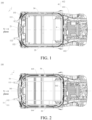
FIG. 1 is a bottom view of a vehicle without a battery pack being mounted according to an embodiment of the present disclosure; -
FIG. 2 is a bottom view of a vehicle with a battery pack being mounted to a vehicle bottom according to an embodiment of the present disclosure; -
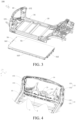
FIG. 3 is an exploded view of a vehicle according to an embodiment of the present disclosure; -
FIG. 4 is a schematic diagram of an A-pillar of a vehicle according to an embodiment of the present disclosure; -
FIG. 5 is a schematic diagram of a rear floor of a vehicle according to an embodiment of the present disclosure; -
FIG. 6 is a schematic diagram of a tail end of a vehicle according to an embodiment of the present disclosure; and -
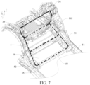
FIG. 7 is a schematic diagram of a tail end of a vehicle with a middle floor being removed according to an embodiment of the present disclosure. - Embodiments of the present disclosure are described in detail below. Examples of the embodiments are shown in accompany drawings. Same or similar elements or elements having same or similar functions are denoted by same or similar reference numerals throughout the description. The embodiments described below with reference to the accompanying drawings are exemplary and intended to explain the present disclosure, and should not be construed as a limitation on the present disclosure.
- In the description of the present disclosure, it should be understood that orientation or position relationships indicated by the terms such as "center", "longitudinal", "transverse", "length", "width", "upper", "lower", "front", "rear", "left", "right", "vertical", "horizontal", "top", "bottom", "inner", "outer", and "circumferential direction" are based on orientation or position relationships shown in the accompanying drawings, and are used only for ease and brevity of illustration and description, rather than indicating or implying that the mentioned apparatus or component must have a particular orientation or must be constructed and operated in a particular orientation. Therefore, such terms should not be construed as a limitation on the present disclosure.
- In the present disclosure, unless otherwise explicitly specified or defined, the terms such as "mount", "connected", "connection", and "fix" should be understood in a broad sense. For example, the connection may be a fixed connection, a detachable connection, or an integral connection; or the connection may be a mechanical connection or an electrical connection; or the connection may be a direct connection, an indirect connection through an intermediate medium, internal communication between two elements, or an interaction relationship between two elements. A person of ordinary skill in the art may understand the specific meanings of the foregoing terms in the present disclosure according to specific situations.
- A
vehicle 100 in the embodiments of the present disclosure is described below with reference toFIG. 1 to FIG. 7 . - Referring to
FIG. 1, FIG. 2 , andFIG. 4 , the embodiments of the present disclosure provide thevehicle 100. The vehicle includes a left frontlongitudinal beam 111, a right frontlongitudinal beam 112, aleft A-pillar 131, aright A-pillar 132, a windshieldupper cross beam 14, and abattery pack 16. The left frontlongitudinal beam 111 and the right frontlongitudinal beam 112 are arranged spaced apart in a width direction of thevehicle 100. The left A-pillar 131 and theright A-pillar 132 are arranged spaced apart in the width direction of thevehicle 100. The left frontlongitudinal beam 111 is connected to a lower section of theleft A-pillar 131. The right frontlongitudinal beam 112 is connected to a lower section of theright A-pillar 132. Two ends of the windshieldupper cross beam 14 are respectively connected to an upper section of theleft A-pillar 131 and an upper section of theright A-pillar 132. Afront end 161 of the battery pack is directly connected to the left frontlongitudinal beam 111 and the right frontlongitudinal beam 112 respectively. The left frontlongitudinal beam 111, the right frontlongitudinal beam 112, theleft A-pillar 131, theright A-pillar 132, the windshieldupper cross beam 14, and thebattery pack 16 form a first A-pillar annular force transmission structure 1. - Referring to
FIG. 1, FIG. 2 , andFIG. 4 , thevehicle 100 in the embodiments of the present disclosure includes a left frontlongitudinal beam 111, a right frontlongitudinal beam 112, aleft A-pillar 131, aright A-pillar 132, a windshieldupper cross beam 14, and abattery pack 16. Theleft A-pillar 131 and theright A-pillar 132 are arranged spaced apart in a width direction of thevehicle 100. Two ends of the windshieldupper cross beam 14 are respectively connected to an upper section of theleft A-pillar 131 and an upper section of theright A-pillar 132, thereby connecting theleft A-pillar 131 and theright A-pillar 132 together at the upper sections thereof. The left frontlongitudinal beam 111 and the right frontlongitudinal beam 112 are arranged spaced apart in the width direction of thevehicle 100. Thefront end 161 of the battery pack is directly connected to the left frontlongitudinal beam 111 and the right frontlongitudinal beam 112 respectively, thereby connecting the left frontlongitudinal beam 111 and the right frontlongitudinal beam 112 together in the width direction of thevehicle 100. The left frontlongitudinal beam 111 is connected to a lower section of theleft A-pillar 131. A rear section of the right longitudinal beam is connected to a lower section of theright A-pillar 132, thereby connecting theleft A-pillar 131 and theright A-pillar 132 at the lower sections thereof. In this case, the left frontlongitudinal beam 111, thebattery pack 16, the right frontlongitudinal beam 112, theright A-pillar 132, the windshieldupper cross beam 14, and theleft A-pillar 131 form a first A-pillar annular force transmission structure 1. Since thebattery pack 16 has relatively great strength and stiffness, thebattery pack 16 is used as a part of the first A-pillar annular force transmission structure 1, which can effectively enhance strength of the first A-pillar annular force transmission structure 1, improve torsional resistance, and improve torsional strength of thevehicle 100. - In this way, in the
vehicle 100 according to the embodiments of the present disclosure, the front end of thebattery pack 161 is directly connected to the left frontlongitudinal beam 111 and the right frontlongitudinal beam 112 respectively, to cause the left frontlongitudinal beam 111, thebattery pack 16, the right frontlongitudinal beam 112, theright A-pillar 132, the windshieldupper cross beam 14, and theleft A-pillar 131 to form the first A-pillar annular force transmission structure 1. Through the first A-pillar annular force transmission structure 1, the torsional strength of thevehicle 100 can be improved. - Compared with some technologies, the
battery pack 16 is only provided with connection points on two sides of thevehicle 100 in the width direction, and is not connected to anA-pillar 13 at the front end of thevehicle 100. In the present disclosure, thefront end 161 of the battery pack is directly connected to the left frontlongitudinal beam 111 and the right frontlongitudinal beam 112 respectively, thereby forming the first A-pillar annular force transmission structure 1 with the left frontlongitudinal beam 111, the right frontlongitudinal beam 112, theright A-pillar 132, the windshieldupper cross beam 14, and theleft A-pillar 131, which can effectively enhance the strength of the first A-pillar annular force transmission structure 1, improve the torsional resistance, and improve the torsional strength of thevehicle 100. - In some embodiments of the present disclosure, referring to
FIG. 1 andFIG. 4 , thevehicle 100 further includes a dashboardlower cross beam 21. The dashboardlower cross beam 21 is arranged between the left frontlongitudinal beam 111 and the right frontlongitudinal beam 112, and is respectively connected to the left frontlongitudinal beam 111 and the right frontlongitudinal beam 112. The left frontlongitudinal beam 111, the right frontlongitudinal beam 112, the left A-pillar 131, the right A-pillar 132, the windshieldupper cross beam 14, and the dashboardlower cross beam 21 form a second A-pillar annularforce transmission structure 2. The second A-pillar annularforce transmission structure 2 is combined with the first A-pillar annular force transmission structure 1 to improve the torsional strength of thevehicle 100. - In some embodiments of the present disclosure, referring to
FIG. 2 , a projection of thebattery pack 16 in an up-down direction of thevehicle 100 at least partially overlaps with a projection of the dashboardlower cross beam 21 in the up-down direction of thevehicle 100, so that thebattery pack 16 and the dashboardlower cross beam 21 at least partially form a superimposed double-layer structure in a height direction of thevehicle 100, which can improve the strength of the first A-pillar annular force transmission structure 1, improve the torsion resistance, and improve the torsional strength of thevehicle 100. - In some embodiments, referring to
FIG. 2 , the projection of the dashboardlower cross beam 21 in the up-down direction of thevehicle 100 completely falls within the projection of thebattery pack 16 in the up-down direction of thevehicle 100. - In some embodiments of the present disclosure, referring to
FIG. 4 , thefront end 161 of the battery pack is directly connected to the dashboardlower cross beam 21. Thefront end 161 of the battery pack is directly connected to the dashboardlower cross beam 21, so that the first A-pillar annular force transmission structure 1 and the second A-pillar annularforce transmission structure 2 are connected together, thereby enhancing the strength of the first A-pillar annular force transmission structure 1, and improving the torsional resistance of thevehicle 100. - In some embodiments of the present disclosure, referring to
FIG. 1 , the left frontlongitudinal beam 111 includes arear section 151 of the left front longitudinal beam. The right frontlongitudinal beam 112 includes arear section 152 of the right front longitudinal beam. Therear section 151 of the left front longitudinal beam is respectively connected to the left A-pillar 131 and the dashboardlower cross beam 21. Therear section 152 of the right front longitudinal beam is respectively connected to the right A-pillar 132 and the dashboardlower cross beam 21. - In some embodiments of the present disclosure, referring to
FIG. 5 and FIG. 6 , thevehicle 100 further includes a rear floorupper cross beam 33, a leftshelf support plate 311, a rightshelf support plate 312, and ashelf connecting plate 32. The leftshelf support plate 311 and the rightshelf support plate 312 are arranged spaced apart in a width direction of thevehicle 100. Two ends of the rear floorupper cross beam 33 are respectively connected to a lower section of the leftshelf support plate 311 and a lower section of the rightshelf support plate 312. Two ends of theshelf connecting plate 32 are respectively connected to an upper section of the leftshelf support plate 311 and an upper section of the rightshelf support plate 312. The rear floorupper cross beam 33, the leftshelf support plate 311, the rightshelf support plate 312, and theshelf connecting plate 32 form a first C-pillarannular structure 3. - The left
shelf support plate 311 and the rightshelf support plate 312 are connected by theshelf connecting plate 32 at the upper sections thereof, and are connected by the rear floorupper cross beam 33 at the lower sections thereof. In this way, the leftshelf support plate 311, theshelf connecting plate 32, the rear floorupper cross beam 33, and the rightshelf support plate 312 form the first C-pillarannular structure 3, which improves the structural strength of thevehicle 100 at a C-pillar. - The rear floor
upper cross beam 33 is arranged at a front end of therear floor 5. Left and right ends of therear floor 5 are respectively connected to an inner wheel housing panel. First joints are connected to two ends of the rear floorupper cross beam 33. The two ends of the rear floorupper cross beam 33 are respectively connected to the leftshelf support plate 311 and the rightshelf support plate 312 through the first joint. The leftshelf support plate 311 includes a left shelf front support plate and a left shelf rear support plate. On a left side of the rear floorupper cross beam 33, upper ends of the first joints are connected to a lower end of the left shelf front support plate and a lower end of the left shelf rear support plate. An upper end of the left shelf front support plate and an upper end of the left shelf rear support plate are connected to one end of theshelf connecting plate 32. On a right side of the rear floorupper cross beam 33, the upper ends of the first joint are connected to a lower end of a right shelf front support plate and a lower end of a right shelf rear support plate. An upper end of the right shelf front support plate and an upper end of the right shelf rear support plate are connected to another end of theshelf connecting plate 32. - In some embodiments of the present disclosure, referring to
FIG. 6 andFIG. 7 , thevehicle 100 further includes a left C-pillar 34 and a right C-pillar 35. The leftshelf support plate 311 is connected to the left C-pillar 34. The rightshelf support plate 312 is connected to the right C-pillar 35. The first C-pillarannular structure 3 is connected to the left C-pillar 34 and the right C-pillar 35 through the leftshelf support plate 311 and the rightshelf support plate 312, which can further effectively enhance the torsional stiffness of thevehicle 100 and improve the torsional resistance while enhancing the strength of the first C-pillarannular structure 3. - In some embodiments of the present disclosure, referring to
FIG. 1 , thevehicle 100 further includes a middle floorlower cross beam 4, a left rearlongitudinal beam 411, and a right rearlongitudinal beam 412. The left rearlongitudinal beam 411 and the right rearlongitudinal beam 412 are arranged spaced apart in the width direction of thevehicle 100. Two ends of the middle floorlower cross beam 4 are respectively connected to the left rearlongitudinal beam 411 and the right rearlongitudinal beam 412. Two ends of the rear floorupper cross beam 33 are respectively connected to the left rearlongitudinal beam 411 and the right rearlongitudinal beam 412. - The left rear
longitudinal beam 411 and the right rearlongitudinal beam 412 are connected at a front end by the middle floorlower cross beam 4 and connected at a rear end by the rear floorupper cross beam 33, thereby forming a closed second C-pillar annular structure, which improves the structural strength of thevehicle 100 in the position, facilitates the overall structural strength of thevehicle 100, and then can effectively improve the torsional stiffness of thevehicle 100 and improve the torsional resistance while enhancing the strength of the first C-pillarannular structure 3. - In some embodiments of the present disclosure, referring to
FIG. 7 , arear end 162 of the battery pack is connected to the middle floorlower cross beam 4, so that thebattery pack 16, a front section of the left rearlongitudinal beam 411, the rear floorupper cross beam 33, and a front section of the right rearlongitudinal beam 412 form a closed third C-pillar annular structure, which improves connection strength between thebattery pack 16 and thevehicle 100, improves the structural strength of thevehicle 100 in the position, and facilitates the overall structural strength of thevehicle 100. In addition, the first C-pillarannular structure 3 can be further enhanced to improve the torsional strength of thevehicle 100. - In some embodiments of the present disclosure, referring to
FIG. 6 andFIG. 7 , thevehicle 100 further includes arear floor 5. The rear floorupper cross beam 33 is connected to therear floor 5. The left rearlongitudinal beam 411 includes a left rear longitudinalbeam sealing plate 51. The left rear longitudinalbeam sealing plate 51 is respectively connected to the middle floorlower cross beam 4 and therear floor 5. The right rearlongitudinal beam 412 includes a right rear longitudinalbeam sealing plate 52. The right rear longitudinalbeam sealing plate 52 is respectively connected to the middle floorlower cross beam 4 and therear floor 5. A fourth C-pillar annular structure is formed by connecting the middle floorlower cross beam 4 and the rear floorupper cross beam 33 by the left rear longitudinalbeam sealing plate 51 and the right rear longitudinalbeam sealing plate 52. The fourth C-pillar annular structure is connected to the first C-pillarannular structure 3, which enhances the strength of the first C-pillarannular structure 3. - In some embodiments of the present disclosure, referring to
FIG. 6 andFIG. 7 , thevehicle 100 further includes a seat mountingcross beam 53. The seat mountingcross beam 53 is respectively connected to the left rear longitudinalbeam sealing plate 51 and the right rear longitudinalbeam sealing plate 52. A fifth C-pillar annular structure may be formed by connecting the seat mountingcross beam 53 and the middle floorlower cross beam 4 by the left rear longitudinalbeam sealing plate 51 and the right rear longitudinalbeam sealing plate 52. The fifth C-pillar annular structure is connected to the first C-pillarannular structure 3, which enhances the strength of the first C-pillarannular structure 3. - In some embodiments of the present disclosure, referring to
FIG. 3 , thevehicle 100 further includes aleft sill beam 54 and aright sill beam 55. Theleft sill beam 54 and theright sill beam 55 are arranged spaced apart in the width direction of thevehicle 100. Theleft sill beam 54 is connected to the left A-pillar 131. Theright sill beam 55 is connected to the right A-pillar 132. Two sides of thebattery pack 16 are directly connected to theleft sill beam 54 and theright sill beam 55 respectively. - The
left sill beam 54 and theright sill beam 55 form mounting beams of thebattery pack 16 on two sides of thevehicle 100. The two sides of thebattery pack 16 are connected to theleft sill beam 54 and theright sill beam 55. Theleft sill beam 54 is connected to the left A-pillar 131, and theright sill beam 55 is connected to the right A-pillar 132, to enable better involvement of thebattery pack 16 in the first A-pillar annular force transmission structure 1, which can better enhance the strength of the first A-pillar annular force transmission structure 1, improve the torsional resistance, and improve the torsional strength of thevehicle 100. - In some embodiments of the present disclosure, the left front
longitudinal beam 111 is connected to theleft sill beam 54, and the right frontlongitudinal beam 112 is connected to theright sill beam 55. The left frontlongitudinal beam 111 is connected to theleft sill beam 54, and the right frontlongitudinal beam 112 is connected to theright sill beam 55, thereby enhancing the strength of the first A-pillar annular force transmission structure 1, improving the torsional resistance, and improving the torsional strength of thevehicle 100. - In some embodiments of the present disclosure, referring to
FIG. 6 andFIG. 7 , thevehicle 100 further includes the middle floorlower cross beam 4. Two ends of the middle floorlower cross beam 4 are connected to theleft sill beam 54 and theright sill beam 55. Therear end 162 of the battery pack is connected to the middle floorlower cross beam 4. The middle floorlower cross beam 4 and the dashboardlower cross beam 21 are connected by theleft sill beam 54, theright sill beam 55, the left frontlongitudinal beam 111, and the right frontlongitudinal beam 112, to form an overall annular force transmission structure. A battery mounting point is arranged on each of theleft sill beam 54, theright sill beam 55, the left frontlongitudinal beam 111, the right frontlongitudinal beam 112, the middle floorlower cross beam 4, and the dashboardlower cross beam 21. Thebattery pack 16 is connected to the overall annular force transmission structure through the battery mounting points, which can enhance the strength of the overall annular force transmission structure, thereby improving the torsional stiffness of thevehicle 100 and improving handling of thevehicle 100. - The left rear longitudinal beam is further connected to the left sill beam, and the right rear longitudinal beam is further connected to the right rear longitudinal beam, so that the left rear longitudinal beam and the right rear longitudinal beam can effectively enhance the strength of the overall annular force transmission structure and improve force transmission capability and the torsional resistance.
- The
front end 161 of the battery pack is connected to the battery mounting point on the dashboardlower cross beam 21. Therear end 162 of the battery pack is connected to the battery mounting point on the middle floorlower cross beam 4. Aleft side 163 of the battery pack is connected to the battery mounting point on theleft sill beam 54. Aright side 164 of the battery pack is connected to the battery mounting point on theright sill beam 55, which can effectively reduce a weight of the vehicle, increase a ground clearance of the vehicle or increase space inside the vehicle, or reduce a vehicle height to improve the handling. - In some embodiments of the present disclosure, at least part of an upper surface of the
battery pack 16 is formed as a floor of thevehicle 100. Thebattery pack 16 is connected to a vehicle body through a battery connection plate, and a gap between thebattery pack 16 and a vehicle body structure is sealed. - In the descriptions of the specification, a description with reference to a term such as "an embodiment", "some embodiments", "an example", "a specific example", or "some examples" means that specific features, structures, materials, or characteristics described with reference to the embodiment or the example are included in at least one embodiment or example of the present disclosure. In this specification, schematic descriptions of the foregoing terms are not necessarily directed at the same embodiment or example. Moreover, the specific features, structures, materials, or characteristics described may be combined in a proper manner in any one or more embodiments or examples. In addition, a person skilled in the art may integrate or combine different embodiments or examples described in the specification and features of the different embodiments or examples as long as they are not contradictory to each other.
- Although the embodiments of the present disclosure have been shown and described above, it may be understood that the above embodiments are exemplary and cannot be construed as a limitation on the present disclosure. A person of ordinary skill in the art may make changes, modifications, replacements, or variations to the above embodiments within the scope of the present disclosure.
Claims (15)
- A vehicle, characterised in that, comprising:a left front longitudinal beam and a right front longitudinal beam, the left front longitudinal beam and the right front longitudinal beam being arranged spaced apart in a width direction of the vehicle;a left A-pillar and a right A-pillar, the left A-pillar and the right A-pillar being arranged spaced apart in the width direction of the vehicle, the left front longitudinal beam being connected to a lower section of the left A-pillar, and the right front longitudinal beam being connected to a lower section of the right A-pillar;a windshield upper cross beam, two ends of the windshield upper cross beam being respectively connected to an upper section of the left A-pillar and an upper section of the right A-pillar; anda battery pack, a front end of the battery pack being directly connected to the left front longitudinal beam and the right front longitudinal beam respectively,wherein the left front longitudinal beam, the right front longitudinal beam, the left A-pillar, the right A-pillar, the windshield upper cross beam, and the battery pack form a first A-pillar annular force transmission structure.
- The vehicle according to claim 1, the vehicle further comprising a dashboard lower cross beam, the dashboard lower cross beam being arranged between the left front longitudinal beam and the right front longitudinal beam, and being respectively connected to the left front longitudinal beam and the right front longitudinal beam,
wherein the left front longitudinal beam, the right front longitudinal beam, the left A-pillar, the right A-pillar, the windshield upper cross beam, and the dashboard lower cross beam form a second A-pillar annular force transmission structure. - The vehicle according to claim 2, wherein a projection of the battery pack in an up-down direction of the vehicle at least partially overlaps with a projection of the dashboard lower cross beam in the up-down direction of the vehicle.
- The vehicle according to claim 3, wherein the front end of the battery pack is directly connected to the dashboard lower cross beam.
- The vehicle according to claim 3 or 4, wherein the left front longitudinal beam comprises a rear section of the left front longitudinal beam, and the right front longitudinal beam comprises a rear section of the right front longitudinal beam,
wherein the rear section of the left front longitudinal beam is respectively connected to the left A-pillar and the dashboard lower cross beam; and the rear section of the right front longitudinal beam is respectively connected to the right A-pillar and the dashboard lower cross beam. - The vehicle according to any of claims 1 to 5, the vehicle further comprising:a rear floor upper cross beam;a left shelf support plate and a right shelf support plate, the left shelf support plate and the right shelf support plate being arranged spaced apart in the width direction of the vehicle, and two ends of the rear floor upper cross beam being respectively connected to a lower section of the left shelf support plate and a lower section of the right shelf support plate; anda shelf connecting plate, two ends of the shelf connecting plate being respectively connected to an upper section of the left shelf support plate and an upper section of the right shelf support plate,wherein the rear floor upper cross beam, the left shelf support plate, the right shelf support plate, and the shelf connecting plate form a first C-pillar annular structure.
- The vehicle according to claim 6, the vehicle further comprising a left C-pillar and a right C-pillar, the left shelf support plate being connected to the left C-pillar, and the right shelf support plate being connected to the right C-pillar.
- The vehicle according to claim 7, the vehicle further comprising:a middle floor lower cross beam; anda left rear longitudinal beam and a right rear longitudinal beam, the left rear longitudinal beam and the right rear longitudinal beam being arranged spaced apart in the width direction of the vehicle, two ends of the middle floor lower cross beam being respectively connected to the left rear longitudinal beam and the right rear longitudinal beam, and the two ends of the rear floor upper cross beam being respectively connected to the left rear longitudinal beam and the right rear longitudinal beam.
- The vehicle according to claim 8, wherein a rear end of the battery pack is connected to the middle floor lower cross beam.
- The vehicle according to claim 9, the vehicle further comprising:a rear floor, the rear floor upper cross beam being connected to the rear floor,the left rear longitudinal beam comprising a left rear longitudinal beam sealing plate, the left rear longitudinal beam sealing plate being respectively connected to the middle floor lower cross beam and the rear floor,the right rear longitudinal beam comprising a right rear longitudinal beam sealing plate, and the right rear longitudinal beam sealing plate being respectively connected to the middle floor lower cross beam and the rear floor.
- The vehicle according to claim 10, the vehicle further comprising:
a seat mounting cross beam, the seat mounting cross beam being respectively connected to the left rear longitudinal beam sealing plate and the right rear longitudinal beam sealing plate. - The vehicle according to any of claims 4 to 11, the vehicle further comprising:
a left sill beam and a right sill beam, the left sill beam and the right sill beam being arranged spaced apart in the width direction of the vehicle, the left sill beam being connected to the left A-pillar, the right sill beam being connected to the right A-pillar, and two sides of the battery pack being directly connected to the left sill beam and the right sill beam respectively. - The vehicle according to claim 12, wherein the left front longitudinal beam is connected to the left sill beam; and the right front longitudinal beam is connected to the right sill beam.
- The vehicle according to claim 12 or 13, the vehicle further comprising:a middle floor lower cross beam, two ends of the middle floor lower cross beam being connected to the left sill beam and the right sill beam, anda rear end of the battery pack being connected to the middle floor lower cross beam.
- The vehicle according to claim 14, wherein at least part of an upper surface of the battery pack is formed as a vehicle floor.
Applications Claiming Priority (2)
| Application Number | Priority Date | Filing Date | Title |
|---|---|---|---|
| CN202210911282.5A CN117508346A (en) | 2022-07-29 | 2022-07-29 | vehicle |
| PCT/CN2023/109873 WO2024022499A1 (en) | 2022-07-29 | 2023-07-28 | Vehicle |
Publications (2)
| Publication Number | Publication Date |
|---|---|
| EP4563445A1 true EP4563445A1 (en) | 2025-06-04 |
| EP4563445A4 EP4563445A4 (en) | 2025-11-05 |
Family
ID=89705519
Family Applications (1)
| Application Number | Title | Priority Date | Filing Date |
|---|---|---|---|
| EP23845703.0A Pending EP4563445A4 (en) | 2022-07-29 | 2023-07-28 | VEHICLE |
Country Status (6)
| Country | Link |
|---|---|
| US (1) | US20250171088A1 (en) |
| EP (1) | EP4563445A4 (en) |
| JP (1) | JP2025524189A (en) |
| KR (1) | KR20250029234A (en) |
| CN (1) | CN117508346A (en) |
| WO (1) | WO2024022499A1 (en) |
Families Citing this family (2)
| Publication number | Priority date | Publication date | Assignee | Title |
|---|---|---|---|---|
| CN114919666A (en) * | 2022-06-06 | 2022-08-19 | 蔚来汽车科技(安徽)有限公司 | Vehicle and front cabin framework of vehicle body |
| CN119821521B (en) * | 2025-02-27 | 2025-10-28 | 浙江极氪智能科技有限公司 | Vehicle body structure and vehicle |
Family Cites Families (13)
| Publication number | Priority date | Publication date | Assignee | Title |
|---|---|---|---|---|
| JP4308285B2 (en) * | 2007-07-17 | 2009-08-05 | 本田技研工業株式会社 | Subframe structure |
| CN104670335A (en) * | 2015-03-17 | 2015-06-03 | 安徽江淮汽车股份有限公司 | Automobile body and automobile |
| CN109204503B (en) * | 2017-06-30 | 2020-12-25 | 比亚迪股份有限公司 | Vehicle body structure and vehicle |
| CN108001540B (en) * | 2017-11-14 | 2020-08-04 | 北京汽车股份有限公司 | Lower vehicle body frame and vehicle with same |
| CN108790760A (en) * | 2018-05-16 | 2018-11-13 | 浙江零跑科技有限公司 | A kind of Battery pack installation structure of electric vehicle |
| CN108609049A (en) * | 2018-06-13 | 2018-10-02 | 力帆实业(集团)股份有限公司 | A kind of electric vehicle lower body frame |
| CN111169547B (en) * | 2018-10-24 | 2021-06-18 | 比亚迪股份有限公司 | Body force transmission structure and automobile |
| CN209479788U (en) * | 2018-12-13 | 2019-10-11 | 威马汽车科技集团有限公司 | Automobile and its body structure |
| CN209667213U (en) * | 2019-03-22 | 2019-11-22 | 广州汽车集团股份有限公司 | A kind of forward engine room assembly structure and the automobile with it |
| CN212099083U (en) * | 2020-03-25 | 2020-12-08 | 广州汽车集团股份有限公司 | A lower body structure and vehicle |
| CN213007574U (en) * | 2020-07-24 | 2021-04-20 | 比亚迪股份有限公司 | Vehicle battery package installation frame and vehicle |
| CN215436623U (en) * | 2021-01-11 | 2022-01-07 | 广州汽车集团股份有限公司 | Steel-aluminum hybrid vehicle body frame structure |
| CN114789754B (en) * | 2021-08-13 | 2024-05-24 | 长城汽车股份有限公司 | Lower rear structure |
-
2022
- 2022-07-29 CN CN202210911282.5A patent/CN117508346A/en active Pending
-
2023
- 2023-07-28 JP JP2025504737A patent/JP2025524189A/en active Pending
- 2023-07-28 KR KR1020257003383A patent/KR20250029234A/en active Pending
- 2023-07-28 EP EP23845703.0A patent/EP4563445A4/en active Pending
- 2023-07-28 WO PCT/CN2023/109873 patent/WO2024022499A1/en not_active Ceased
-
2025
- 2025-01-27 US US19/037,903 patent/US20250171088A1/en active Pending
Also Published As
| Publication number | Publication date |
|---|---|
| JP2025524189A (en) | 2025-07-25 |
| WO2024022499A1 (en) | 2024-02-01 |
| US20250171088A1 (en) | 2025-05-29 |
| CN117508346A (en) | 2024-02-06 |
| EP4563445A4 (en) | 2025-11-05 |
| KR20250029234A (en) | 2025-03-04 |
Similar Documents
| Publication | Publication Date | Title |
|---|---|---|
| US20250171088A1 (en) | Vehicle | |
| US11124237B2 (en) | Front structure of vehicle body | |
| US8668252B2 (en) | Vehicle body floor structure | |
| US11807306B2 (en) | Vehicle body structure | |
| US10086881B2 (en) | Front vehicle body structure | |
| CN110304152B (en) | Front body structure of vehicle | |
| CN110304151B (en) | Front body structure of vehicle | |
| CN207826349U (en) | Automobile front wall structure and body of a motor car | |
| CN110304149B (en) | Front body structure of vehicle | |
| US12612111B2 (en) | Rear vehicle body structure | |
| US12420868B2 (en) | Rear structure of vehicle body | |
| KR20230099254A (en) | Front vehicle body structure | |
| CN115892246A (en) | Floor structure and have its vehicle behind automobile body | |
| CN116902088A (en) | vehicle body components and vehicle | |
| CN112849271B (en) | Vehicle front structure | |
| CN218505983U (en) | Vehicle body tail frame structure and vehicle | |
| US20250136183A1 (en) | Vehicle | |
| CN219838625U (en) | Vehicle with a vehicle body having a vehicle body support | |
| US20240190519A1 (en) | Joint structure of vehicle body | |
| US11541946B2 (en) | Transmission mount of rear wheel drive vehicle | |
| JP2023139435A (en) | vehicle subframe | |
| US20230202571A1 (en) | Side Body Structure for Vehicle | |
| US20250222988A1 (en) | Front structure of vehicle body | |
| KR20230099255A (en) | Front vehicle body structure | |
| CN119283978B (en) | Rear body structure and vehicle |
Legal Events
| Date | Code | Title | Description |
|---|---|---|---|
| STAA | Information on the status of an ep patent application or granted ep patent |
Free format text: STATUS: THE INTERNATIONAL PUBLICATION HAS BEEN MADE |
|
| PUAI | Public reference made under article 153(3) epc to a published international application that has entered the european phase |
Free format text: ORIGINAL CODE: 0009012 |
|
| STAA | Information on the status of an ep patent application or granted ep patent |
Free format text: STATUS: REQUEST FOR EXAMINATION WAS MADE |
|
| 17P | Request for examination filed |
Effective date: 20250227 |
|
| AK | Designated contracting states |
Kind code of ref document: A1 Designated state(s): AL AT BE BG CH CY CZ DE DK EE ES FI FR GB GR HR HU IE IS IT LI LT LU LV MC ME MK MT NL NO PL PT RO RS SE SI SK SM TR |
|
| A4 | Supplementary search report drawn up and despatched |
Effective date: 20251006 |
|
| DAV | Request for validation of the european patent (deleted) | ||
| DAX | Request for extension of the european patent (deleted) | ||
| RIC1 | Information provided on ipc code assigned before grant |
Ipc: B62D 21/02 20060101AFI20250929BHEP Ipc: B62D 25/20 20060101ALI20250929BHEP Ipc: B60K 1/04 20190101ALI20250929BHEP Ipc: B62D 25/08 20060101ALI20250929BHEP Ipc: B62D 25/04 20060101ALI20250929BHEP Ipc: B62D 25/14 20060101ALI20250929BHEP |