EP4563442A1 - Adaptor, adaptor apparatus, and child carrier - Google Patents
Adaptor, adaptor apparatus, and child carrier Download PDFInfo
- Publication number
- EP4563442A1 EP4563442A1 EP24216409.3A EP24216409A EP4563442A1 EP 4563442 A1 EP4563442 A1 EP 4563442A1 EP 24216409 A EP24216409 A EP 24216409A EP 4563442 A1 EP4563442 A1 EP 4563442A1
- Authority
- EP
- European Patent Office
- Prior art keywords
- adaptor
- fitting
- locking member
- operating
- groove
- Prior art date
- Legal status (The legal status is an assumption and is not a legal conclusion. Google has not performed a legal analysis and makes no representation as to the accuracy of the status listed.)
- Pending
Links
Images






Classifications
-
- B—PERFORMING OPERATIONS; TRANSPORTING
- B62—LAND VEHICLES FOR TRAVELLING OTHERWISE THAN ON RAILS
- B62B—HAND-PROPELLED VEHICLES, e.g. HAND CARTS OR PERAMBULATORS; SLEDGES
- B62B7/00—Carriages for children; Perambulators, e.g. dolls' perambulators
- B62B7/04—Carriages for children; Perambulators, e.g. dolls' perambulators having more than one wheel axis; Steering devices therefor
- B62B7/14—Carriages for children; Perambulators, e.g. dolls' perambulators having more than one wheel axis; Steering devices therefor with detachable or rotatably-mounted body
- B62B7/142—Means for securing the body to the frame
-
- B—PERFORMING OPERATIONS; TRANSPORTING
- B62—LAND VEHICLES FOR TRAVELLING OTHERWISE THAN ON RAILS
- B62B—HAND-PROPELLED VEHICLES, e.g. HAND CARTS OR PERAMBULATORS; SLEDGES
- B62B9/00—Accessories or details specially adapted for children's carriages or perambulators
- B62B9/10—Perambulator bodies; Equipment therefor
- B62B9/12—Perambulator bodies; Equipment therefor involving parts that are adjustable, attachable or detachable
-
- A—HUMAN NECESSITIES
- A47—FURNITURE; DOMESTIC ARTICLES OR APPLIANCES; COFFEE MILLS; SPICE MILLS; SUCTION CLEANERS IN GENERAL
- A47D—FURNITURE SPECIALLY ADAPTED FOR CHILDREN
- A47D13/00—Other nursery furniture
- A47D13/02—Baby-carriers; Carry-cots
- A47D13/025—Baby-carriers; Carry-cots for carrying children in seated position
-
- B—PERFORMING OPERATIONS; TRANSPORTING
- B62—LAND VEHICLES FOR TRAVELLING OTHERWISE THAN ON RAILS
- B62B—HAND-PROPELLED VEHICLES, e.g. HAND CARTS OR PERAMBULATORS; SLEDGES
- B62B7/00—Carriages for children; Perambulators, e.g. dolls' perambulators
- B62B7/04—Carriages for children; Perambulators, e.g. dolls' perambulators having more than one wheel axis; Steering devices therefor
- B62B7/14—Carriages for children; Perambulators, e.g. dolls' perambulators having more than one wheel axis; Steering devices therefor with detachable or rotatably-mounted body
-
- B—PERFORMING OPERATIONS; TRANSPORTING
- B62—LAND VEHICLES FOR TRAVELLING OTHERWISE THAN ON RAILS
- B62B—HAND-PROPELLED VEHICLES, e.g. HAND CARTS OR PERAMBULATORS; SLEDGES
- B62B2205/00—Hand-propelled vehicles or sledges being foldable or dismountable when not in use
- B62B2205/20—Catches; Locking or releasing an articulation
-
- B—PERFORMING OPERATIONS; TRANSPORTING
- B62—LAND VEHICLES FOR TRAVELLING OTHERWISE THAN ON RAILS
- B62B—HAND-PROPELLED VEHICLES, e.g. HAND CARTS OR PERAMBULATORS; SLEDGES
- B62B2205/00—Hand-propelled vehicles or sledges being foldable or dismountable when not in use
- B62B2205/30—Detachable, retractable or collapsible load supporting means
Definitions
- the present disclosure relates to the field of child appliance technologies, and in particular, to an adaptor, an adaptor apparatus, and a child carrier.
- An adaptor can be used to detachably mount a baby carrier, such as a baby seat or a carry cot, on a baby stroller.
- Conventional adaptors generally have complex structures and are inconvenient to operate.
- the present disclosure provides an adaptor, an adaptor apparatus, and a child carrier, which are easy to operate and have a small space.
- an adaptor is provided.
- the adaptor is used for a child carrier including a carrier body and a frame body.
- the adaptor includes a connecting base, a locking member, an operating member, and a traction assembly.
- the connecting base has a first connecting portion and a second connecting portion, the first connecting portion being adapted to be connected to the carrier body.
- the locking member is movably arranged on the second connecting portion of the connecting base and has a lock position and an unlock position, when the locking member is at the lock position, the locking member is configured to lock a fitting member arranged on the frame body to connect the adaptor to the frame body, and when the locking member is at the unlock position, the locking member is configured to unlock the fitting member to allow the adaptor to be separated from the frame body.
- the operating member is movably arranged on the connecting base.
- the traction assembly is connected to the locking member and the operating member respectively. The operating member is operable to drive the traction assembly to drive the locking member to move from the lock position to the unlock position.
- the fitting member is a clamping rod
- the locking member is rotatably arranged on the second connecting portion and has a hook portion, the hook portion being configured to be engaged with the fitting member.
- the second connecting portion is provided with an engaging groove, the engaging groove being configured to be engaged with a side wall of a fitting base arranged on the frame body.
- the second connecting portion is provided with a locking groove.
- the locking member When the locking member is at the lock position, the locking member at least partially extends into the locking groove and locks the fitting member, so as to limit the fitting member within the locking groove.
- the locking member When the locking member is at the unlock position, the locking member exits the locking groove, thereby allowing the fitting member to be separated from the connecting base.
- the adaptor further includes a reset member, the reset member being connected to the locking member, and the reset member being adapted to bias the locking member to move the locking member towards the lock position.
- the traction assembly includes: a traction member and a sheath.
- One end of the traction member is connected to the locking member, and the other end of the traction member is connected to the operating member.
- the sheath sleeves the traction member.
- the connecting base includes a first housing and a second housing, the first housing being provided with an accommodating groove, the second housing covering a groove opening of the accommodating groove, at least part of the operating member is accommodated in the accommodating groove, and the traction assembly is accommodated in the accommodating groove; and
- the locking member has a pivot portion, the pivot portion being rotatably arranged in the accommodating groove, and when the locking member is at the lock position, at least part of the hook portion is capable of extending out of the accommodating groove.
- a side wall of the accommodating groove is provided with an operating port, the operating port being in communication with the accommodating groove, and the operating member is movably inserted into the operating port and has a first position and a second position.
- the operating member has an operating portion, and when the operating member is at the first position, at least part of the operating portion extends out of the accommodating groove.
- the traction assembly includes a traction member, the traction member including a first end, a second end, and a middle part between the first end and the second end, the first end being connected to the locking member, and the second end being connected to the operating member.
- the connecting base is provided with a protruding portion, and the middle part abuts against the protruding portion.
- the operating member is movably arranged on the connecting base, and when the operating member moves from the first position to the second position, a distance between the first end and the second end decreases.
- the second housing is provided with an operating port, the operating port being in communication with the accommodating groove.
- the operating member includes a main body portion and an operating portion, the main body portion being movably arranged in the accommodating groove, and the operating member at least partially extends out of the accommodating groove through the operating port.
- an adaptor apparatus includes a fitting assembly and the adaptor in any one of the above embodiments.
- the fitting assembly is configured to be connected to a frame body of a child carrier, the fitting assembly includes a fitting base and a fitting member arranged on the fitting base, and the fitting assembly has a receiving groove and is provided with the fitting member.
- the connecting base of the adaptor is adapted to be at least partially inserted into the receiving groove, and the locking member selectively locks the fitting member.
- the fitting member is a clamping rod, two ends of the clamping rod being connected to a pair of side walls of the receiving groove respectively.
- the second connecting portion of the connecting base is provided with an engaging groove, and at least part of the second connecting portion is inserted into the receiving groove, the engaging groove being engaged with a side wall of the receiving groove.
- a child carrier includes a frame body, a carrier body, and the adaptor apparatus in any one of the above embodiments.
- the fitting assembly of the adaptor apparatus is connected to the frame body, and the adaptor of the adaptor apparatus is detachably connected to the fitting assembly and the carrier body.
- the frame body includes a wheel frame and a seat frame connected to the wheel frame.
- Two adaptor apparatuses are provided, and each fitting assembly is connected to the wheel frame and the seat frame respectively.
- first and second are used for descriptive purposes only, which cannot be construed as indicating or implying a relative importance, or implicitly specifying the number of the indicated technical features. Therefore, the features defined with “first” and “second” may explicitly or implicitly include at least one feature. In the description of the present disclosure, "a plurality of” means at least two, such as two or three, unless otherwise defined explicitly and specifically.
- the terms “mount”, “connect”, “join”, and “fix” should be understood in a broad sense, which may be, for example, a fixed connection, a detachable connection, or an integral connection; a mechanical connection or an electrical connection; or a direct connection, an indirect connection via an intermediate medium, an internal connection between two elements, or interaction between two elements. Those of ordinary skill in the art can understand specific meanings of these terms in the present disclosure according to specific situations.
- a first feature being “on” or “under” a second feature may be the case that the first feature is in direct contact with the second feature, or the first feature is in indirect contact with the second feature via an intermediate medium.
- the expression the first feature being “over”, “above” and “on top of” the second feature may be the case that the first feature is directly above or obliquely above the second feature, or only means that the level of the first feature is higher than that of the second feature.
- the expression the first feature being "below”, “underneath” or “under” the second feature may be the case that the first feature is directly underneath or obliquely underneath the second feature, or only means that the level of the first feature is lower than that of the second feature.
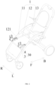
- FIG. 1 is a perspective view of a child carrier according to some embodiments of the present disclosure.
- the child carrier includes a frame body 1, a carrier body 2, and an adaptor apparatus 30.
- the carrier body 2 is detachably connected to the frame body 1 through the adaptor apparatus 30.
- the child carrier is, for example, a child stroller.
- the child stroller may be a single stroller, a double stroller, or the like.
- the carrier body may be, for example, a carry cot, a stroller seat, or the like.
- the adaptor apparatus 30 includes an adaptor 3 and a fitting assembly 4.
- the adaptor 3 is detachably connected to the fitting assembly 4.
- the adaptor 3 and the adaptor apparatus 30 are described together below when the child carrier is described.
- the frame body 1 includes a wheel frame 11, a push handle 13, and a seat frame 12 connected to the wheel frame 11 and the push handle 13.
- the seat frame 12 may be further provided with another stroller seat, so that the child carrier can accommodate two children (including infants and toddlers) at the same time.
- the child carrier may alternatively be provided only with the carrier body 2. By replacing different types of carrier bodies 2, the child carrier can meet requirements of children of different ages and sizes in different scenarios.
- the seat frame 12 is substantially U-shaped, and the seat frame 12 has two free end portions 121.
- the two free end portions 121 When the child carrier is in an unfolded state, the two free end portions 121 respectively extend in a direction away from the push handle 13 (that is, forward in a front-rear direction).
- the two free end portions 121 are each provided with the fitting assembly 4.
- the two fitting assemblies 4 are respectively fixedly connected or detachably connected to the wheel frame 11.
- the adaptor 3 is connected to the carrier body 2 and the fitting assembly 4 respectively, to detachably connect the carrier body 2 to the frame body 1. That is, the carrier body 2 is respectively connected to the two free end portions 121 of the seat frame 12 through two adaptor apparatuses 30.
- the stroller seat may also be directly connected to the fitting assembly 4, which is not limited in the present disclosure.
- orientation terms related to the child carrier such as “front”, “rear”, “upper”, “lower”, “left”, and “right” are based on “front”, “back”, “upper”, “lower”, “left”, and “right” orientations of the child carrier traveling normally.
- arrows L and R schematically show “left” and “right” directions
- arrows F and B schematically show “front” and “rear” directions.
- the two adaptor apparatuses 30 are symmetrically arranged on the frame body 1, and structures of the two adaptor apparatuses 30 are mirrored symmetrically in a left-right direction.
- the adaptor apparatus 30 provided on the left side of the frame body 1 is used as an example for description.
- the fitting assembly 4 includes a fitting base 42 and a fitting member 41 arranged on the fitting base 42.
- the fitting base 42 is substantially cuboid.
- the fitting base 42 has a receiving groove 425.
- the receiving groove 425 has a front side wall 421 and a rear side wall 422 that are substantially located in the front-rear direction, and a left side wall 423 and a right side wall 424 that are substantially located in the left-right direction.
- the rear side wall 422 is connected to the free end portion 121 of the seat frame 12 and is detachably connected to the wheel frame 11 through a connecting member (such as a screw, a bolt, or a rivet).
- the fitting member 41 is accommodated in the receiving groove 425.
- the fitting member 41 is, for example, a clamping rod, and two ends of the clamping rod are connected to a pair of side walls of the receiving groove 425 respectively. More specifically, one end of the clamping rod is connected to the left side wall 423, the other end of the clamping rod is connected to the right side wall 424, and the fitting member 41 extends substantially along the left-right direction.
- the fitting member 41 may be located outside the receiving groove 425 of the fitting base 42.
- the fitting base 42 may not be provided, and the fitting member 41 is directly arranged on the frame body 1 (e.g., the seat frame 12), which is not limited in the present disclosure.
- the adaptor 3 includes a connecting base 31, a locking member 32, an operating member 33, a traction assembly 34, and a reset member 35.
- the connecting base 31 is substantially L-shaped.
- the connecting base 31 has a first connecting portion 311 and a second connecting portion 312.
- the first connecting portion 311 extends upwards substantially along an up-down direction.
- the second connecting portion 312 extends rearwards substantially along the front-rear direction.
- the first connecting portion 311 is adapted to be connected to the carrier body 2.
- the first connecting portion 311 is adapted to be detachably connected to a side portion of the carrier body 2.
- the second connecting portion 312 is adapted to be detachably connected to the frame body 1.
- the second connecting portion 312 of the connecting base 31 is provided with an engaging groove 317, an opening of the engaging groove 317 is downward, and an opening of the receiving groove 425 of the fitting base 42 is upward.
- the connecting base 31 is in insertion fit with the fitting base 42 substantially in the up-down direction. That is, an insertion direction of the connecting base 31 and the fitting base 42 is substantially perpendicular to a normal traveling direction of the child carrier. In this way, during normal traveling of the child carrier, the separation of the connecting base 31 from the fitting base 42 can be better restricted.
- at least part of the second connecting portion 312 is inserted into the receiving groove 425, and the engaging groove 317 is engaged with a side wall of the receiving groove 425.
- the engaging groove 317 passes through left and right sides of the connecting base 31. That is, the engaging groove 317 extends substantially along the left-right direction, and the engaging groove 317 is engaged with the front side wall 421 of the receiving groove 425.
- Left and right sides of the second connecting portion 312 are limited respectively by inner walls of the receiving groove 425, so as to restrict movement of the adaptor 3 relative to the fitting assembly 4 in the left-right direction.
- One end of the second connecting portion 312 away from the first connecting portion 311 has a limiting protrusion 3121.
- the limiting protrusion 3121 abuts against an end face of the rear side wall 422 of the receiving groove 425. In this way, the second connecting portion 312 can be inserted into the receiving groove 425 more firmly, reducing relative shaking between the connecting base 31 and the fitting base 42.
- the locking member 32 When the locking member 32 is at the unlock position, the locking member 32 unlocks the fitting member 41 (i.e., the locking member 32 is separated from the fitting member 41, so as to allow the adaptor 3 to be separated from the fitting assembly 4 to allow the adaptor 3 to be separated from the frame body 1, thereby allowing the carrier body 2 to be separated from the frame body 1.
- the carrier body 2 can be detachably mounted on the frame body 1 easily.
- the second connecting portion 312 is provided with a locking groove 313, and the fitting member 41 (i.e., the clamping rod) is adapted to be engaged in the locking groove 313.
- a groove opening of the locking groove 313 is downward, the locking groove 313 passes through left and right sides of the connecting base 31, and an extension direction of the locking groove 313 is substantially the same as that of the engaging groove 317.
- the hook portion 321 at least partially extends into the locking groove 313 and is engaged with the clamping rod, to limit the fitting member 41 in the locking groove 313. At least part of the hook portion 321 is below the clamping rod.
- the adaptor 3 cannot move relative to the fitting assembly 4 in both the front-rear and up-down directions. Therefore, movement of the carrier body 2 relative to the frame body 1 in the front-rear and up-down directions can be restricted.
- the hook portion 321 exits the locking groove 313, thereby allowing the fitting member 41 to be separated from the connecting base 31.
- movement of the fitting member 41 in the up-down direction and the front-rear direction can be restricted, so as to connect the adaptor 3 to the fitting assembly 4 more firmly.
- the reset member 35 is connected to the locking member 32, and the reset member 35 is adapted to bias the locking member 32 to rotate the locking member 32 towards the lock position, and the operating member 33 is driven by the traction assembly 34 to move from the second position to the first position.
- the reset member 35 is, for example, a torsional spring
- the reset member 35 is arranged in the accommodating groove 314 and sleeves the boss portion 318, one pin of the reset member 35 (i.e., the torsional spring) abuts against the locking member 32, and the other pin of the reset member 35 (i.e., the torsional spring) abuts against an inner wall of the accommodating groove 314.
- the reset member 35 is in an elastic energy storage state, and an elastic restoring force of the reset member 35 causes the locking member 32 to have a tendency to rotate towards the lock position.
- the operating member 33 is movably arranged on the connecting base 31 and is drivingly connected to the locking member 32 through the traction assembly 34. Specifically, at least part of the operating member 33 is accommodated in the accommodating groove 314.
- the operating member 33 has a first position and a second position. When the operating member 33 is at the first position, the locking member 32 is at the lock position where engagement with the fitting member 41 can be realized, so as to fixedly connect the connecting base 31 to the fitting assembly 4.
- the operating member 33 drives, through the traction assembly 34, the locking member 32 to move from the lock position to the unlock position.
- the locking member 32 rotates to the unlock position where disengagement from the fitting member 41 can be realized, so that the connecting base 31 can be separated from the fitting assembly 4 and the reset member 35 is in the elastic energy storage state.
- the locking member 32 rotates from the unlock position to the lock position under the elastic restoring force of the reset member 35, and the operating member 33 is driven by the traction assembly 34 to move from the second position and return to the first position.
- the operating member 33 is connected to the locking member 32 through the traction assembly 34, and there is no need to tie a position of the operating member 33 to a position of the locking member 32 (that is, the position of the operating member 33 may not be restricted by the structure and the position of the locking member 32), so that the position of the operating member 33 can be set more flexibly, thereby facilitating a user's operation.
- the operating member 33 and the locking member 32 are arranged relatively far away from each other.
- a length of a rotating arm that rotates the locking member 32 can be adjusted by adjusting a connection position between the traction assembly 34 and the locking member 32, which helps realize a remote operation on the operating member 33 (even if the locking member 32 has a longer rotating arm), so that the user can operate the operating member 33 with less effort.
- the operating member 33 can reduce their footprint, thereby reducing an overall volume of the adaptor 3.
- the traction assembly 34 is accommodated in the accommodating groove 314 and connected between the locking member 32 and the operating member 33.
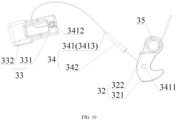
- the traction assembly 34 includes a traction member 341 and a sheath 342. One end (i.e., a first end 3411) of the traction member 341 is connected to the locking member 32. Referring to FIG. 10 , the other end (i.e., a second end 3412) of the traction member 341 is connected to the operating member 33.
- the traction member 341 includes a traction rope (such as a steel wire, a steel cable, or a carbon fiber rope) and a first terminal and a second terminal that are respectively provided at two ends of the traction rope.
- the first terminal serves as the first end 3411
- the second terminal serves as the second end 3412
- the traction rope forms a middle part 3413 of the traction member 341.
- the traction member 341 may not be provided with the first terminal and/or the second terminal, one end of the traction rope serves as the first end 3411, and/or the other end of the traction rope serves as the second end 3412, which is not limited in the present disclosure.
- the sheath 342 sleeves the traction member 341. Specifically, the sheath 342 sleeves the traction rope of the traction member 341.
- the sheath 342 is configured to guide an extension direction of the traction member 341 and prevent entanglement and knotting of the traction member 341 in a loose state.
- the sheath 342 is connected to the connecting base 31.
- the sheath 342 may alternatively sleeve the traction member 341 and is not connected to the connecting base 31, which is not limited in the present disclosure.
- a side wall of the accommodating groove 314 is provided with an operating port 315, the operating port 315 is substantially located at the first connecting portion 311 of the connecting base 31, and the operating port 315 is in communication with the accommodating groove 314.
- the operating port 315 is located on a side of the first connecting portion 311 away from the limiting protrusion 3121 (i.e., the operating port 315 is located on a front side surface of the first connecting portion 311).
- the operating member 33 is movably inserted into the operating port 315.
- the operating member 33 can move substantially in the front-rear direction. In this embodiment, when the operating portion 332 is pressed along the front-rear direction, the operating member 33 moves from the first position to the second position.
- the operating member 33 has a main body portion 331 and an operating portion 332.
- the main body portion 331 is accommodated in the accommodating groove 314 and connected to the second end 3412 of the traction member 341.
- the operating member 33 is at the first position, at least part of the operating portion 332 extends out of the accommodating groove 314, so that the operating member 33 can be moved by operating the operating portion 332.
- the connecting base 31 is provided with a protruding portion 316, and the protruding portion 316 may be arranged next to the operating member 33, or may be arranged between the operating member 33 and the bottom wall of the accommodating groove 314.
- the middle part 3413 of the traction member 341 abuts against the protruding portion 316. That is, the middle part 3413 of the traction member 341 detours from the protruding portion 316 to change a movement direction of the traction member 341.
- the first end 3411 of the traction member 341 is connected to the locking member 32, and the second end 3412 passes through or passes around the protruding portion 316 and is connected to the main body portion 331 of the operating member 33.
- a movement direction of the second end 3412 of the traction member 341 can be changed, so that when the operating member 332 moves towards the locking member 32, the traction member 341 is in a tensioned state, thereby driving the locking member 32 to rotate towards the operating member 33.
- the operating portion 332 when the operating portion 332 is pressed to move the operating member 33 from the first position to the second position (i.e., the operating member 33 is pressed to move backwards), the operating member 33 moves towards the locking member 32, a distance between the first end 3411 and the second end 3412 decreases, and the traction member 341 is in the tensioned state, thereby driving the locking member 32 to rotate from the lock position to the unlock position.
- the operating member 33 When a pressing force on the operating member 33 is removed (i.e., the operating member 33 is not pressed), the operating member 33 no longer applies an external force to the traction member 341, the locking member 32 rotates from the unlock position to the lock position under the elastic restoring force of the reset member 35, and the operating member 33 is driven by the traction member 341 to move forward from the second position and return to the first position. In this process, the operating member 33 and the locking member 32 are switched to positions away from each other, and the distance between the first end 3411 and the second end 3412 increases.
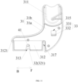
- FIG. 11 is a right view of the adaptor 3 according to some other embodiments of the present disclosure. This embodiment has at least the following differences from the above embodiments.
- the operating port 315 is arranged on the second housing 3 1b, and the operating port 315 is in communication with the accommodating groove 314.
- the operating member 33 includes a main body portion 331 and an operating portion 332.
- the main body portion 331 is movably arranged in the accommodating groove 314.
- the bottom wall of the accommodating groove 314 is provided with a guide groove 43.
- the main body portion 331 is slidably connected to the guide groove 43.
- the operating member 33 at least partially extends out of the accommodating groove 314 through the operating port 315, so that the operating portion 332 is operated to move the operating member 33 between the first position and the second position. In this embodiment, the operating member 33 moves substantially in the up-down direction.
- the operating member 33 when the operating portion 332 of the operating member 33 is pulled upwards in the up-down direction, the operating member 33 moves from the first position to the second position, and the traction member 341 is in the tensioned state, thereby driving the locking member 32 to rotate from the lock position to the unlock position.
- the operating member 33 When the operating member 33 is no longer pulled, the operating member 33 no longer applies an external force to the traction member 341, the locking member 32 rotates from the unlock position to the lock position under the elastic restoring force of the reset member 35, and the operating member 33 is driven by the traction member 341 to move downwards from the second position and return to the first position.
Landscapes
- Engineering & Computer Science (AREA)
- Chemical & Material Sciences (AREA)
- Combustion & Propulsion (AREA)
- Transportation (AREA)
- Mechanical Engineering (AREA)
- Health & Medical Sciences (AREA)
- Public Health (AREA)
- Carriages For Children, Sleds, And Other Hand-Operated Vehicles (AREA)
- Accommodation For Nursing Or Treatment Tables (AREA)
Abstract
An adaptor (3) for a child carrier including a carrier body (2) and a frame body (1) is disclosed. The adaptor includes: a connecting base (31), a locking member (32), an operating member (33), and a traction assembly (34). The connecting base has a first connecting portion (311) and a second connecting portion (312). The first connecting portion (311) is adapted to be connected to the carrier body (2). The locking member (32) is movably arranged on the second connecting portion (312) and has a lock position and an unlock position. When the locking member (32) is at the lock position, the locking member (32) locks a fitting member (41) arranged on the frame body (1) to connect the adaptor (3) to the frame body (1), and when the locking member (32) is at the unlock position, the locking member (32) unlocks the fitting member (41) to allow the adaptor (3) to be separated from the frame body (1).
Description
- The present disclosure relates to the field of child appliance technologies, and in particular, to an adaptor, an adaptor apparatus, and a child carrier.
- An adaptor can be used to detachably mount a baby carrier, such as a baby seat or a carry cot, on a baby stroller. Conventional adaptors generally have complex structures and are inconvenient to operate.
- The present disclosure provides an adaptor, an adaptor apparatus, and a child carrier, which are easy to operate and have a small space.
- According to an aspect of the present disclosure, an adaptor is provided. The adaptor is used for a child carrier including a carrier body and a frame body. The adaptor includes a connecting base, a locking member, an operating member, and a traction assembly. The connecting base has a first connecting portion and a second connecting portion, the first connecting portion being adapted to be connected to the carrier body. The locking member is movably arranged on the second connecting portion of the connecting base and has a lock position and an unlock position, when the locking member is at the lock position, the locking member is configured to lock a fitting member arranged on the frame body to connect the adaptor to the frame body, and when the locking member is at the unlock position, the locking member is configured to unlock the fitting member to allow the adaptor to be separated from the frame body. The operating member is movably arranged on the connecting base. The traction assembly is connected to the locking member and the operating member respectively. The operating member is operable to drive the traction assembly to drive the locking member to move from the lock position to the unlock position.
- In an embodiment, the fitting member is a clamping rod, and the locking member is rotatably arranged on the second connecting portion and has a hook portion, the hook portion being configured to be engaged with the fitting member.
- In an embodiment, the second connecting portion is provided with an engaging groove, the engaging groove being configured to be engaged with a side wall of a fitting base arranged on the frame body.
- In an embodiment, the second connecting portion is provided with a locking groove. When the locking member is at the lock position, the locking member at least partially extends into the locking groove and locks the fitting member, so as to limit the fitting member within the locking groove. When the locking member is at the unlock position, the locking member exits the locking groove, thereby allowing the fitting member to be separated from the connecting base.
- In an embodiment, the adaptor further includes a reset member, the reset member being connected to the locking member, and the reset member being adapted to bias the locking member to move the locking member towards the lock position.
- In an embodiment, the traction assembly includes: a traction member and a sheath. One end of the traction member is connected to the locking member, and the other end of the traction member is connected to the operating member. The sheath sleeves the traction member.
- In an embodiment, the connecting base includes a first housing and a second housing, the first housing being provided with an accommodating groove, the second housing covering a groove opening of the accommodating groove, at least part of the operating member is accommodated in the accommodating groove, and the traction assembly is accommodated in the accommodating groove; and
- The locking member has a pivot portion, the pivot portion being rotatably arranged in the accommodating groove, and when the locking member is at the lock position, at least part of the hook portion is capable of extending out of the accommodating groove.
- In an embodiment, a side wall of the accommodating groove is provided with an operating port, the operating port being in communication with the accommodating groove, and the operating member is movably inserted into the operating port and has a first position and a second position. The operating member has an operating portion, and when the operating member is at the first position, at least part of the operating portion extends out of the accommodating groove.
- In an embodiment, the traction assembly includes a traction member, the traction member including a first end, a second end, and a middle part between the first end and the second end, the first end being connected to the locking member, and the second end being connected to the operating member. The connecting base is provided with a protruding portion, and the middle part abuts against the protruding portion. The operating member is movably arranged on the connecting base, and when the operating member moves from the first position to the second position, a distance between the first end and the second end decreases.
- In an embodiment, the second housing is provided with an operating port, the operating port being in communication with the accommodating groove. The operating member includes a main body portion and an operating portion, the main body portion being movably arranged in the accommodating groove, and the operating member at least partially extends out of the accommodating groove through the operating port.
- According to another aspect of the present disclosure, an adaptor apparatus is provided. The adaptor apparatus includes a fitting assembly and the adaptor in any one of the above embodiments. The fitting assembly is configured to be connected to a frame body of a child carrier, the fitting assembly includes a fitting base and a fitting member arranged on the fitting base, and the fitting assembly has a receiving groove and is provided with the fitting member. The connecting base of the adaptor is adapted to be at least partially inserted into the receiving groove, and the locking member selectively locks the fitting member.
- In an embodiment, the fitting member is a clamping rod, two ends of the clamping rod being connected to a pair of side walls of the receiving groove respectively.
- In an embodiment, the second connecting portion of the connecting base is provided with an engaging groove, and at least part of the second connecting portion is inserted into the receiving groove, the engaging groove being engaged with a side wall of the receiving groove.
- According to yet another aspect of the present disclosure, a child carrier is provided. The child carrier includes a frame body, a carrier body, and the adaptor apparatus in any one of the above embodiments. The fitting assembly of the adaptor apparatus is connected to the frame body, and the adaptor of the adaptor apparatus is detachably connected to the fitting assembly and the carrier body.
- In an embodiment, the frame body includes a wheel frame and a seat frame connected to the wheel frame. Two adaptor apparatuses are provided, and each fitting assembly is connected to the wheel frame and the seat frame respectively.
- The accompanying drawings forming part of the present disclosure are intended to provide further understanding of the present disclosure. Exemplary embodiments of the present disclosure and descriptions thereof are intended to explain the present disclosure, and do not constitute any inappropriate limitation on the present disclosure.
- In order to more clearly illustrate the technical solutions in embodiments of the present disclosure, the accompanying drawings used in the description of the embodiments will be briefly introduced below. It is apparent that, the accompanying drawings in the following description are only some embodiments of the present disclosure, and other drawings can be obtained by those of ordinary skill in the art from the provided drawings without creative efforts.
- In addition, the accompanying drawings are not drawn to 1: 1 scale, and relative sizes of various elements in the accompanying drawings are drawn by way of examples only to facilitate understanding of the present disclosure, and not necessarily to true scale. In the drawings;
-
FIG. 1 is a perspective view of a child carrier according to some embodiments of the present disclosure; -
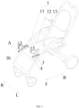
FIG. 2 is a perspective view of the child carrier inFIG. 1 after a carrier body is removed; -
FIG. 3 is a perspective view of the child carrier inFIG. 1 after the carrier body and an adaptor are removed; -
FIG. 4 is a schematic exploded view of an adaptor apparatus of the child carrier inFIG. 1 ; -
FIG. 5 is an enlarged view of a portion A inFIG. 4 ; -
FIG. 6 is a left view of the adaptor according to some embodiments of the present disclosure; -
FIG. 7 is a right view of the adaptor inFIG. 6 ; -
FIG. 8 is a right view of the adaptor inFIG. 7 after a second housing is removed, with a locking member being at a lock position; -
FIG. 9 is a right view of the adaptor inFIG. 7 after the second housing is removed, with the locking member being at an unlock position; -
FIG. 10 is a perspective view of the adaptor inFIG. 6 after a connecting base is removed; -
FIG. 11 is a right view of the adaptor according to some other embodiments of the present disclosure; -
FIG. 12 is a right view of the adaptor inFIG. 11 after the second housing is removed, with the locking member being at the lock position; and -
FIG. 13 is a perspective view of the adaptor inFIG. 11 after the connecting base is removed. - In order to make the above objectives, features, and advantages of the present disclosure more obvious and understandable, specific implementations of the present disclosure are described in detail below with reference to the accompanying drawings. In the following description, many specific details are set forth in order to fully understand the present disclosure. However, the present disclosure can be implemented in many other ways different from those described herein, and those skilled in the art can make similar improvements without departing from the connotation of the present disclosure. Therefore, the present disclosure is not limited by the specific embodiments disclosed below.
- In the description of the present disclosure, it should be understood that the orientation or position relationships indicated by the terms "central", "longitudinal", "transverse", "length", "width", "thickness", "upper", "lower", "front", "back", "left", "right", "vertical", "horizontal", "top", "bottom", "inner", "outer", "clockwise", "counterclockwise", "axial", "radial", "circumferential", and the like are based on the orientation or position relationships shown in the accompanying drawings and are intended to facilitate the description of the present disclosure and simplify the description only, rather than indicating or implying that the apparatus or element referred to must have a particular orientation or be constructed and operated in a particular orientation, and therefore are not to be interpreted as limiting the present disclosure.
- In addition, the terms "first" and "second" are used for descriptive purposes only, which cannot be construed as indicating or implying a relative importance, or implicitly specifying the number of the indicated technical features. Therefore, the features defined with "first" and "second" may explicitly or implicitly include at least one feature. In the description of the present disclosure, "a plurality of" means at least two, such as two or three, unless otherwise defined explicitly and specifically.
- In the present disclosure, unless otherwise specified and defined explicitly, the terms "mount", "connect", "join", and "fix" should be understood in a broad sense, which may be, for example, a fixed connection, a detachable connection, or an integral connection; a mechanical connection or an electrical connection; or a direct connection, an indirect connection via an intermediate medium, an internal connection between two elements, or interaction between two elements. Those of ordinary skill in the art can understand specific meanings of these terms in the present disclosure according to specific situations.
- In the present disclosure, unless otherwise explicitly specified and defined, the expression a first feature being "on" or "under" a second feature may be the case that the first feature is in direct contact with the second feature, or the first feature is in indirect contact with the second feature via an intermediate medium. Furthermore, the expression the first feature being "over", "above" and "on top of" the second feature may be the case that the first feature is directly above or obliquely above the second feature, or only means that the level of the first feature is higher than that of the second feature. The expression the first feature being "below", "underneath" or "under" the second feature may be the case that the first feature is directly underneath or obliquely underneath the second feature, or only means that the level of the first feature is lower than that of the second feature.
- It should be noted that when one element is referred to as being "fixed to" or "arranged on" another element, it may be directly disposed on the another element or an intermediate element may exist. When one element is considered to be "connected to" another element, it may be directly connected to the another element or an intermediate element may co-exist. The terms "vertical", "horizontal", "left", "right" and similar expressions used herein are for illustrative purposes only and do not represent an only implementation.
- The present disclosure provides an
adaptor 3, anadaptor apparatus 30, and a child carrier provided with theadaptor apparatus 30. Referring toFIG. 1, FIG. 1 is a perspective view of a child carrier according to some embodiments of the present disclosure. The child carrier includes aframe body 1, acarrier body 2, and anadaptor apparatus 30. Thecarrier body 2 is detachably connected to theframe body 1 through theadaptor apparatus 30. The child carrier is, for example, a child stroller. The child stroller may be a single stroller, a double stroller, or the like. The carrier body may be, for example, a carry cot, a stroller seat, or the like. Theadaptor apparatus 30 includes anadaptor 3 and afitting assembly 4. Theadaptor 3 is detachably connected to thefitting assembly 4. Theadaptor 3 and theadaptor apparatus 30 are described together below when the child carrier is described. - As shown in
FIG. 1 to FIG. 3 , theframe body 1 includes awheel frame 11, apush handle 13, and aseat frame 12 connected to thewheel frame 11 and the push handle 13. In some embodiments, in addition to thecarrier body 2, theseat frame 12 may be further provided with another stroller seat, so that the child carrier can accommodate two children (including infants and toddlers) at the same time. Certainly, in some other embodiments, the child carrier may alternatively be provided only with thecarrier body 2. By replacing different types ofcarrier bodies 2, the child carrier can meet requirements of children of different ages and sizes in different scenarios. Referring toFIG. 1 to FIG. 3 , theseat frame 12 is substantially U-shaped, and theseat frame 12 has twofree end portions 121. When the child carrier is in an unfolded state, the twofree end portions 121 respectively extend in a direction away from the push handle 13 (that is, forward in a front-rear direction). The twofree end portions 121 are each provided with thefitting assembly 4. The twofitting assemblies 4 are respectively fixedly connected or detachably connected to thewheel frame 11. Theadaptor 3 is connected to thecarrier body 2 and thefitting assembly 4 respectively, to detachably connect thecarrier body 2 to theframe body 1. That is, thecarrier body 2 is respectively connected to the twofree end portions 121 of theseat frame 12 through twoadaptor apparatuses 30. In other embodiments not illustrated, when thecarrier body 2 is a stroller seat, the stroller seat may also be directly connected to thefitting assembly 4, which is not limited in the present disclosure. - It should be noted that, unless otherwise explicitly specified and defined, in various embodiments of the present disclosure, orientation terms related to the child carrier such as "front", "rear", "upper", "lower", "left", and "right" are based on "front", "back", "upper", "lower", "left", and "right" orientations of the child carrier traveling normally. In the figure, arrows L and R schematically show "left" and "right" directions, and arrows F and B schematically show "front" and "rear" directions. These orientation terms are intended only to make the description of the embodiments of the present disclosure clearer and are not intended to unduly limit the protection scope of the present disclosure.
- As shown in
FIG. 2 andFIG. 4 , the twoadaptor apparatuses 30 are symmetrically arranged on theframe body 1, and structures of the twoadaptor apparatuses 30 are mirrored symmetrically in a left-right direction. For ease of description, theadaptor apparatus 30 provided on the left side of theframe body 1 is used as an example for description. - Referring to
FIG. 4 andFIG. 5 , thefitting assembly 4 includes afitting base 42 and afitting member 41 arranged on thefitting base 42. Thefitting base 42 is substantially cuboid. Thefitting base 42 has a receivinggroove 425. The receivinggroove 425 has afront side wall 421 and arear side wall 422 that are substantially located in the front-rear direction, and aleft side wall 423 and aright side wall 424 that are substantially located in the left-right direction. Therear side wall 422 is connected to thefree end portion 121 of theseat frame 12 and is detachably connected to thewheel frame 11 through a connecting member (such as a screw, a bolt, or a rivet). In this embodiment, at least part of thefitting member 41 is accommodated in the receivinggroove 425. Specifically, thefitting member 41 is, for example, a clamping rod, and two ends of the clamping rod are connected to a pair of side walls of the receivinggroove 425 respectively. More specifically, one end of the clamping rod is connected to theleft side wall 423, the other end of the clamping rod is connected to theright side wall 424, and thefitting member 41 extends substantially along the left-right direction. Certainly, in some other embodiments not illustrated, thefitting member 41 may be located outside the receivinggroove 425 of thefitting base 42. In some other embodiments not illustrated, thefitting base 42 may not be provided, and thefitting member 41 is directly arranged on the frame body 1 (e.g., the seat frame 12), which is not limited in the present disclosure. - As shown in
FIG. 6 to FIG. 9 , theadaptor 3 includes a connectingbase 31, a lockingmember 32, an operatingmember 33, atraction assembly 34, and areset member 35. The connectingbase 31 is substantially L-shaped. The connectingbase 31 has a first connectingportion 311 and a second connectingportion 312. The first connectingportion 311 extends upwards substantially along an up-down direction. The second connectingportion 312 extends rearwards substantially along the front-rear direction. Referring toFIG. 1 andFIG. 2 together, the first connectingportion 311 is adapted to be connected to thecarrier body 2. Specifically, the first connectingportion 311 is adapted to be detachably connected to a side portion of thecarrier body 2. The second connectingportion 312 is adapted to be detachably connected to theframe body 1. - As shown in
FIG. 5 to FIG. 7 , the second connectingportion 312 of the connectingbase 31 is provided with an engaginggroove 317, an opening of the engaginggroove 317 is downward, and an opening of the receivinggroove 425 of thefitting base 42 is upward. The connectingbase 31 is in insertion fit with thefitting base 42 substantially in the up-down direction. That is, an insertion direction of the connectingbase 31 and thefitting base 42 is substantially perpendicular to a normal traveling direction of the child carrier. In this way, during normal traveling of the child carrier, the separation of the connectingbase 31 from thefitting base 42 can be better restricted. In this embodiment, at least part of the second connectingportion 312 is inserted into the receivinggroove 425, and the engaginggroove 317 is engaged with a side wall of the receivinggroove 425. The engaginggroove 317 passes through left and right sides of the connectingbase 31. That is, the engaginggroove 317 extends substantially along the left-right direction, and the engaginggroove 317 is engaged with thefront side wall 421 of the receivinggroove 425. Left and right sides of the second connectingportion 312 are limited respectively by inner walls of the receivinggroove 425, so as to restrict movement of theadaptor 3 relative to thefitting assembly 4 in the left-right direction. One end of the second connectingportion 312 away from the first connectingportion 311 has a limitingprotrusion 3121. When the second connectingportion 312 is in insertion fit with the receivinggroove 425, the limitingprotrusion 3121 abuts against an end face of therear side wall 422 of the receivinggroove 425. In this way, the second connectingportion 312 can be inserted into the receivinggroove 425 more firmly, reducing relative shaking between the connectingbase 31 and thefitting base 42. - In some embodiments, as shown in
FIG. 8 to FIG. 10 , the lockingmember 32 is movably arranged on the connectingbase 31. Specifically, the lockingmember 32 is rotatably arranged on the second connectingportion 312 of the connectingbase 31 and has a lock position and an unlock position. When the lockingmember 32 is at the lock position, the lockingmember 32 locks thefitting member 41 to connect theadaptor 3 to theframe body 1. Thefitting assembly 4 is arranged on theframe body 1, and theadaptor 3 is detachably connected to thecarrier body 2. Therefore, through the fit between theadaptor 3 and thefitting member 41 of thefitting assembly 4, thecarrier body 2 is fixed to theframe body 1. When the lockingmember 32 is at the unlock position, the lockingmember 32 unlocks the fitting member 41 (i.e., the lockingmember 32 is separated from thefitting member 41, so as to allow theadaptor 3 to be separated from thefitting assembly 4 to allow theadaptor 3 to be separated from theframe body 1, thereby allowing thecarrier body 2 to be separated from theframe body 1. In this way, through theadaptor 3 and theadaptor apparatus 30 according to this embodiment, thecarrier body 2 can be detachably mounted on theframe body 1 easily. - Referring to
FIG. 7 to FIG. 9 , the connectingbase 31 includes afirst housing 31a and asecond housing 31b, and thesecond housing 31b is detachably connected to thefirst housing 31a. Thefirst housing 31a is provided with anaccommodating groove 314, and thesecond housing 31b covers a groove opening of theaccommodating groove 314. The lockingmember 32 is at least partially accommodated in theaccommodating groove 314. The lockingmember 32 has ahook portion 321 and apivot portion 322. Thehook portion 321 is adapted to be engaged with the clampingrod 41, to realize a detachable connection between theadaptor 3 and thefitting assembly 4. Thepivot portion 322 is rotatably arranged in theaccommodating groove 314. When the lockingmember 32 is at the lock position, at least part of thehook portion 321 can extend out of theaccommodating groove 314 to be engaged with thefitting member 41. When the lockingmember 32 is at the unlock position, thehook portion 321 retracts into theaccommodating groove 314 to be disengaged from thefitting member 41. Specifically, thefirst housing 31a is provided with aboss portion 318, theboss portion 318 is located in theaccommodating groove 314 and is fixedly connected to or integrally formed on a bottom wall of theaccommodating groove 314, thepivot portion 322 of the lockingmember 32 is rotatably arranged on theboss portion 318, and theboss portion 318 limits an axis of rotation of the lockingmember 32. The axis of rotation extends substantially along the left-right direction. In this embodiment, the second connectingportion 312 is provided with a lockinggroove 313, and the fitting member 41 (i.e., the clamping rod) is adapted to be engaged in the lockinggroove 313. A groove opening of the lockinggroove 313 is downward, the lockinggroove 313 passes through left and right sides of the connectingbase 31, and an extension direction of the lockinggroove 313 is substantially the same as that of the engaginggroove 317. When the lockingmember 32 is at the lock position, thehook portion 321 at least partially extends into the lockinggroove 313 and is engaged with the clamping rod, to limit thefitting member 41 in the lockinggroove 313. At least part of thehook portion 321 is below the clamping rod. Through a joint limiting effect of thehook portion 321 and a groove wall of the lockinggroove 313 on the clamping rod, theadaptor 3 cannot move relative to thefitting assembly 4 in both the front-rear and up-down directions. Therefore, movement of thecarrier body 2 relative to theframe body 1 in the front-rear and up-down directions can be restricted. When the lockingmember 32 is at the unlock position, thehook portion 321 exits the lockinggroove 313, thereby allowing thefitting member 41 to be separated from the connectingbase 31. Through the fitting between the lockinggroove 313 and the lockingmember 32, movement of thefitting member 41 in the up-down direction and the front-rear direction can be restricted, so as to connect theadaptor 3 to thefitting assembly 4 more firmly. - Still referring to
FIG. 7 to FIG. 9 , thereset member 35 is connected to the lockingmember 32, and thereset member 35 is adapted to bias the lockingmember 32 to rotate the lockingmember 32 towards the lock position, and the operatingmember 33 is driven by thetraction assembly 34 to move from the second position to the first position. In this embodiment, thereset member 35 is, for example, a torsional spring, thereset member 35 is arranged in theaccommodating groove 314 and sleeves theboss portion 318, one pin of the reset member 35 (i.e., the torsional spring) abuts against the lockingmember 32, and the other pin of the reset member 35 (i.e., the torsional spring) abuts against an inner wall of theaccommodating groove 314. When the lockingmember 32 is at the unlock position, thereset member 35 is in an elastic energy storage state, and an elastic restoring force of thereset member 35 causes the lockingmember 32 to have a tendency to rotate towards the lock position. - In some embodiments, as shown in
FIG. 7 to FIG. 9 , the operatingmember 33 is movably arranged on the connectingbase 31 and is drivingly connected to the lockingmember 32 through thetraction assembly 34. Specifically, at least part of the operatingmember 33 is accommodated in theaccommodating groove 314. The operatingmember 33 has a first position and a second position. When the operatingmember 33 is at the first position, the lockingmember 32 is at the lock position where engagement with thefitting member 41 can be realized, so as to fixedly connect the connectingbase 31 to thefitting assembly 4. When the operatingmember 33 moves from the first position to the second position under an external force, the operatingmember 33 drives, through thetraction assembly 34, the lockingmember 32 to move from the lock position to the unlock position. When the operatingmember 33 moves to the second position, the lockingmember 32 rotates to the unlock position where disengagement from thefitting member 41 can be realized, so that the connectingbase 31 can be separated from thefitting assembly 4 and thereset member 35 is in the elastic energy storage state. When no external force is applied to the operatingmember 33, the lockingmember 32 rotates from the unlock position to the lock position under the elastic restoring force of thereset member 35, and the operatingmember 33 is driven by thetraction assembly 34 to move from the second position and return to the first position. - In this embodiment, the operating
member 33 is connected to the lockingmember 32 through thetraction assembly 34, and there is no need to tie a position of the operatingmember 33 to a position of the locking member 32 (that is, the position of the operatingmember 33 may not be restricted by the structure and the position of the locking member 32), so that the position of the operatingmember 33 can be set more flexibly, thereby facilitating a user's operation. In this embodiment, the operatingmember 33 and the lockingmember 32 are arranged relatively far away from each other. In this way, a length of a rotating arm that rotates the lockingmember 32 can be adjusted by adjusting a connection position between thetraction assembly 34 and the lockingmember 32, which helps realize a remote operation on the operating member 33 (even if the lockingmember 32 has a longer rotating arm), so that the user can operate the operatingmember 33 with less effort. In addition, in this embodiment, through the connection between thetraction assembly 34 and the lockingmember 32, the operatingmember 33 can reduce their footprint, thereby reducing an overall volume of theadaptor 3. - Referring to
FIG. 8 to FIG. 9 , thetraction assembly 34 is accommodated in theaccommodating groove 314 and connected between the lockingmember 32 and the operatingmember 33. Thetraction assembly 34 includes atraction member 341 and asheath 342. One end (i.e., a first end 3411) of thetraction member 341 is connected to the lockingmember 32. Referring toFIG. 10 , the other end (i.e., a second end 3412) of thetraction member 341 is connected to the operatingmember 33. Thetraction member 341 includes a traction rope (such as a steel wire, a steel cable, or a carbon fiber rope) and a first terminal and a second terminal that are respectively provided at two ends of the traction rope. The first terminal serves as thefirst end 3411, the second terminal serves as thesecond end 3412, and the traction rope forms amiddle part 3413 of thetraction member 341. In some other embodiments not illustrated, thetraction member 341 may not be provided with the first terminal and/or the second terminal, one end of the traction rope serves as thefirst end 3411, and/or the other end of the traction rope serves as thesecond end 3412, which is not limited in the present disclosure. Thesheath 342 sleeves thetraction member 341. Specifically, thesheath 342 sleeves the traction rope of thetraction member 341. Thesheath 342 is configured to guide an extension direction of thetraction member 341 and prevent entanglement and knotting of thetraction member 341 in a loose state. In this embodiment, at least one end of thesheath 342 is connected to the connectingbase 31. Certainly, in other embodiments not illustrated, thesheath 342 may alternatively sleeve thetraction member 341 and is not connected to the connectingbase 31, which is not limited in the present disclosure. - As shown in
FIG. 8 to FIG. 10 , a side wall of theaccommodating groove 314 is provided with anoperating port 315, the operatingport 315 is substantially located at the first connectingportion 311 of the connectingbase 31, and the operatingport 315 is in communication with theaccommodating groove 314. Specifically, the operatingport 315 is located on a side of the first connectingportion 311 away from the limiting protrusion 3121 (i.e., the operatingport 315 is located on a front side surface of the first connecting portion 311). The operatingmember 33 is movably inserted into the operatingport 315. The operatingmember 33 can move substantially in the front-rear direction. In this embodiment, when the operatingportion 332 is pressed along the front-rear direction, the operatingmember 33 moves from the first position to the second position. The operatingmember 33 has amain body portion 331 and an operatingportion 332. Themain body portion 331 is accommodated in theaccommodating groove 314 and connected to thesecond end 3412 of thetraction member 341. When the operatingmember 33 is at the first position, at least part of the operatingportion 332 extends out of theaccommodating groove 314, so that the operatingmember 33 can be moved by operating the operatingportion 332. - As shown in
FIG. 8 to FIG. 10 , the connectingbase 31 is provided with a protrudingportion 316, and the protrudingportion 316 may be arranged next to the operatingmember 33, or may be arranged between the operatingmember 33 and the bottom wall of theaccommodating groove 314. Themiddle part 3413 of thetraction member 341 abuts against the protrudingportion 316. That is, themiddle part 3413 of thetraction member 341 detours from the protrudingportion 316 to change a movement direction of thetraction member 341. In other words, thefirst end 3411 of thetraction member 341 is connected to the lockingmember 32, and thesecond end 3412 passes through or passes around the protrudingportion 316 and is connected to themain body portion 331 of the operatingmember 33. In this way, a movement direction of thesecond end 3412 of thetraction member 341 can be changed, so that when the operatingmember 332 moves towards the lockingmember 32, thetraction member 341 is in a tensioned state, thereby driving the lockingmember 32 to rotate towards the operatingmember 33. - In this embodiment, when the operating
portion 332 is pressed to move the operatingmember 33 from the first position to the second position (i.e., the operatingmember 33 is pressed to move backwards), the operatingmember 33 moves towards the lockingmember 32, a distance between thefirst end 3411 and thesecond end 3412 decreases, and thetraction member 341 is in the tensioned state, thereby driving the lockingmember 32 to rotate from the lock position to the unlock position. When a pressing force on the operatingmember 33 is removed (i.e., the operatingmember 33 is not pressed), the operatingmember 33 no longer applies an external force to thetraction member 341, the lockingmember 32 rotates from the unlock position to the lock position under the elastic restoring force of thereset member 35, and the operatingmember 33 is driven by thetraction member 341 to move forward from the second position and return to the first position. In this process, the operatingmember 33 and the lockingmember 32 are switched to positions away from each other, and the distance between thefirst end 3411 and thesecond end 3412 increases. -
FIG. 11 is a right view of theadaptor 3 according to some other embodiments of the present disclosure. This embodiment has at least the following differences from the above embodiments. - In another embodiment, as shown in
FIG. 11 to FIG. 13 , the operatingport 315 is arranged on thesecond housing 3 1b, and the operatingport 315 is in communication with theaccommodating groove 314. The operatingmember 33 includes amain body portion 331 and an operatingportion 332. Themain body portion 331 is movably arranged in theaccommodating groove 314. The bottom wall of theaccommodating groove 314 is provided with aguide groove 43. Themain body portion 331 is slidably connected to theguide groove 43. The operatingmember 33 at least partially extends out of theaccommodating groove 314 through the operatingport 315, so that the operatingportion 332 is operated to move the operatingmember 33 between the first position and the second position. In this embodiment, the operatingmember 33 moves substantially in the up-down direction. - In this embodiment, when the operating
portion 332 of the operatingmember 33 is pulled upwards in the up-down direction, the operatingmember 33 moves from the first position to the second position, and thetraction member 341 is in the tensioned state, thereby driving the lockingmember 32 to rotate from the lock position to the unlock position. When the operatingmember 33 is no longer pulled, the operatingmember 33 no longer applies an external force to thetraction member 341, the lockingmember 32 rotates from the unlock position to the lock position under the elastic restoring force of thereset member 35, and the operatingmember 33 is driven by thetraction member 341 to move downwards from the second position and return to the first position. - The technical features in the above embodiments may be randomly combined. For concise description, not all possible combinations of the technical features in the above embodiments are described. However, all the combinations of the technical features are to be considered as falling within the scope described in this specification provided that they do not conflict with each other.
- The above embodiments only describe several implementations of the present disclosure, and their description is specific and detailed, but cannot therefore be understood as a limitation on the patent scope of the present disclosure. It should be noted that those of ordinary skill in the art may further make variations and improvements without departing from the conception of the present disclosure.
Claims (15)
- An adaptor (3) for a child carrier including a carrier body (2) and a frame body (1), the adaptor (3) comprising:a connecting base (31) having a first connecting portion (311) and a second connecting portion (312), the first connecting portion (311) being adapted to be connected to the carrier body (2);a locking member (32) movably arranged on the second connecting portion (312) of the connecting base (31) and having a lock position and an unlock position, wherein, when the locking member (32) is at the lock position, the locking member (32) being configured to lock a fitting member (41) arranged on the frame body (1) to connect the adaptor (3) to the frame body (1), and when the locking member (32) is at the unlock position, the locking member (32) being configured to unlock the fitting member (41) to allow the adaptor (3) to be separated from the frame body (1);an operating member (33) movably arranged on the connecting base (31); anda traction assembly (34) connected to the locking member (32) and the operating member (33) respectively;wherein the operating member (33) is operable to drive the traction assembly (34) to drive the locking member (32) to move from the lock position to the unlock position.
- The adaptor (3) of claim 1, wherein the fitting member (41) is a clamping rod, and the locking member (32) is rotatably arranged on the second connecting portion (312) and has a hook portion (321) configured to be engaged with the fitting member (41).
- The adaptor (3) of claim 1 or 2, wherein the second connecting portion (312) is provided with an engaging groove (317) configured to be engaged with a side wall of a fitting base (42) arranged on the frame body (1).
- The adaptor (3) of any one of claims 1 to 3, wherein:the second connecting portion (312) is provided with a locking groove (313); andwhen the locking member (32) is at the lock position, the locking member (32) at least partially extends into the locking groove (313) and locks the fitting member (41), so as to limit the fitting member (41) within the locking groove (313), and when the locking member (32) is at the unlock position, the locking member (32) exits the locking groove (313), thereby allowing the fitting member (41) to be separated from the connecting base (31).
- The adaptor (3) of any one of claims 1 to 4, further comprising a reset member (35), the reset member (35) being connected to the locking member (32), and the reset member (35) being adapted to bias the locking member (32) to move the locking member (32) towards the lock position.
- The adaptor (3) of any one of claims 1 to 5, wherein the traction assembly (34) comprises:a traction member (341) having an end connected to the locking member (32), and another end connected to the operating member (33); anda sheath (342) sleeving the traction member (341).
- The adaptor (3) of claim 2, optionally in combination with any one of the claims 3 to 6, wherein:the connecting base (31) comprises a first housing (31a) and a second housing (31b), the first housing (31a) being provided with an accommodating groove (314), the second housing (31b) covering a groove opening of the accommodating groove (314), wherein at least part of the operating member (33) is accommodated in the accommodating groove (314), and the traction assembly (34) is accommodated in the accommodating groove (314); andthe locking member (32) has a pivot portion (322), the pivot portion (322) being rotatably arranged in the accommodating groove (314), and when the locking member (32) is at the lock position, at least part of the hook portion (321) is capable of extending out of the accommodating groove (314).
- The adaptor (3) of claim 7, wherein:a side wall of the accommodating groove (314) is provided with an operating port (315), the operating port (315) being in communication with the accommodating groove (314), and the operating member (33) is movably inserted into the operating port (315) and has a first position and a second position; andthe operating member (33) has an operating portion (332), and when the operating member (33) is at the first position, at least part of the operating portion (332) extends out of the accommodating groove (314).
- The adaptor (3) of claim 7 or 8, wherein:the second housing (31b) is provided with an operating port (315), the operating port (315) being in communication with the accommodating groove (314); andthe operating member (33) comprises a main body portion (331) and an operating portion (332), the main body portion (331) being movably arranged in the accommodating groove (314), and the operating member (33) at least partially extends out of the accommodating groove (314) through the operating port (315).
- The adaptor (3) of any one of claims 1 to 9, wherein:the traction assembly (34) comprises a traction member (341), wherein the traction member (341) comprising a first end (3411), a second end (3412), and a middle part (3413) between the first end (3411) and the second end (3412), the first end (3411) being connected to the locking member (32), and the second end (3412) being connected to the operating member (33);the connecting base (31) is provided with a protruding portion (316), and the middle part (3413) abuts against the protruding portion (316); andthe operating member (33) is movably arranged on the connecting base (31), and when the operating member (33) moves from the first position to the second position, a distance between the first end (3411) and the second end (3412) decreases.
- An adaptor apparatus (30), comprising:the adaptor (3) of any one of claims 1 to 10; anda fitting assembly (4) configured to be connected to a frame body (1) of a child carrier, the fitting assembly (4) comprising a fitting base (42) and a fitting member (41) arranged on the fitting base (42), the fitting assembly (4) having a receiving groove (425) and being provided with the fitting member (41),wherein the connecting base (31) of the adaptor (3) is adapted to be at least partially inserted into the receiving groove (425), and the locking member (32) is adapted to selectively lock the fitting member (41).
- The adaptor apparatus (30) of claim 11, wherein the fitting member (41) is a clamping rod, two ends of the clamping rod being connected to a pair of side walls of the receiving groove (425) respectively.
- The adaptor apparatus (30) of claim 11 or 12, wherein the second connecting portion (312) of the connecting base (31) is provided with an engaging groove (317), and at least part of the second connecting portion (312) is inserted into the receiving groove (425), the engaging groove (317) being engaged with a side wall of the receiving groove (425).
- A child carrier, comprising:a frame body (1);a carrier body (2); andthe adaptor apparatus (30) of any one of claims 11 to 13,wherein the fitting assembly (4) of the adaptor apparatus (30) is connected to the frame body (1), and the adaptor (3) of the adaptor apparatus (30) is detachably connected to the fitting assembly (4) and the carrier body (2).
- The child carrier of claim 14, wherein:the frame body (1) comprises a wheel frame (11) and a seat frame (12) connected to the wheel frame (11); andtwo adaptor apparatuses (30) are provided, and each fitting assembly (4) is connected to the wheel frame (11) and the seat frame (12) respectively.
Applications Claiming Priority (1)
| Application Number | Priority Date | Filing Date | Title |
|---|---|---|---|
| CN202311628035.5A CN120057084A (en) | 2023-11-30 | 2023-11-30 | Adapter, adapter device and child carrier |
Publications (1)
| Publication Number | Publication Date |
|---|---|
| EP4563442A1 true EP4563442A1 (en) | 2025-06-04 |
Family
ID=93742734
Family Applications (1)
| Application Number | Title | Priority Date | Filing Date |
|---|---|---|---|
| EP24216409.3A Pending EP4563442A1 (en) | 2023-11-30 | 2024-11-29 | Adaptor, adaptor apparatus, and child carrier |
Country Status (4)
| Country | Link |
|---|---|
| US (1) | US20250178658A1 (en) |
| EP (1) | EP4563442A1 (en) |
| CN (1) | CN120057084A (en) |
| TW (1) | TW202523540A (en) |
Families Citing this family (1)
| Publication number | Priority date | Publication date | Assignee | Title |
|---|---|---|---|---|
| TWD237995S (en) * | 2023-09-14 | 2025-05-01 | 瑞士商明門瑞士股份有限公司 (瑞士) | Child stroller adapter |
Citations (4)
| Publication number | Priority date | Publication date | Assignee | Title |
|---|---|---|---|---|
| DE202007009450U1 (en) * | 2007-07-05 | 2007-10-04 | Curt Würstl Vermögensverwaltungs-Gmbh & Co. Kg | Adapter for children's or pushchair car racks |
| EP1808354B1 (en) * | 2006-01-12 | 2009-08-05 | Play, S.A. | Combination of an adapter, an infant pushchair and an infant article |
| CN210101727U (en) * | 2019-05-20 | 2020-02-21 | 湖北睿智儿童用品有限公司 | Joint, children's handcart and children's car seat |
| US11685419B2 (en) * | 2021-01-08 | 2023-06-27 | Wonderland Switzerland Ag | Child stroller apparatus |
-
2023
- 2023-11-30 CN CN202311628035.5A patent/CN120057084A/en active Pending
-
2024
- 2024-11-14 TW TW113143885A patent/TW202523540A/en unknown
- 2024-11-26 US US18/961,268 patent/US20250178658A1/en active Pending
- 2024-11-29 EP EP24216409.3A patent/EP4563442A1/en active Pending
Patent Citations (4)
| Publication number | Priority date | Publication date | Assignee | Title |
|---|---|---|---|---|
| EP1808354B1 (en) * | 2006-01-12 | 2009-08-05 | Play, S.A. | Combination of an adapter, an infant pushchair and an infant article |
| DE202007009450U1 (en) * | 2007-07-05 | 2007-10-04 | Curt Würstl Vermögensverwaltungs-Gmbh & Co. Kg | Adapter for children's or pushchair car racks |
| CN210101727U (en) * | 2019-05-20 | 2020-02-21 | 湖北睿智儿童用品有限公司 | Joint, children's handcart and children's car seat |
| US11685419B2 (en) * | 2021-01-08 | 2023-06-27 | Wonderland Switzerland Ag | Child stroller apparatus |
Also Published As
| Publication number | Publication date |
|---|---|
| US20250178658A1 (en) | 2025-06-05 |
| TW202523540A (en) | 2025-06-16 |
| CN120057084A (en) | 2025-05-30 |
Similar Documents
| Publication | Publication Date | Title |
|---|---|---|
| JP7355907B2 (en) | Stroller with folding mechanism triggered by child carrier | |
| US5865447A (en) | Controlling structure of a stroller | |
| US20250178658A1 (en) | Adaptor, adaptor apparatus, and child carrier | |
| US8251382B2 (en) | Stroller and seat assembly mechanism for a stroller | |
| US8827283B2 (en) | Mounting system and method of installing a child support accessory on a stroller frame | |
| EP4737269A2 (en) | Child stroller apparatus | |
| EP1180448B1 (en) | Child seat base | |
| CN105313940A (en) | stroller device | |
| US12037039B2 (en) | Child stroller apparatus | |
| EP3708462B1 (en) | A carriage frame folding device that can be unlocked along with the folding of the seat | |
| US12280816B2 (en) | Stroller, stroller frame and folding device thereof | |
| GB2445628A (en) | A safety guard mounting device | |
| WO2005054001A1 (en) | One-hand fold handle for infant carrier | |
| CN114802407A (en) | Fixing device, and passenger device and carrier device using the same | |
| TWI847906B (en) | Folding joint and child carrier | |
| CN104553905B (en) | Child safety seat for automobiles | |
| JP2006071888A (en) | Connector plug of optical connector and optical connector | |
| JP5331733B2 (en) | Electric vacuum cleaner | |
| CN221068188U (en) | Baby carriage frame | |
| CN221642541U (en) | Connecting seats, carriers and child carriers | |
| CN223850475U (en) | Connection structure and infant carrier | |
| WO2025168056A1 (en) | Child safety seat | |
| CN204367930U (en) | Child safety seat for automobiles | |
| EP4454973A1 (en) | Seat-equipped childcare apparatus | |
| CN104670047B (en) | Car safety child seat |
Legal Events
| Date | Code | Title | Description |
|---|---|---|---|
| PUAI | Public reference made under article 153(3) epc to a published international application that has entered the european phase |
Free format text: ORIGINAL CODE: 0009012 |
|
| STAA | Information on the status of an ep patent application or granted ep patent |
Free format text: STATUS: REQUEST FOR EXAMINATION WAS MADE |
|
| 17P | Request for examination filed |
Effective date: 20241129 |
|
| AK | Designated contracting states |
Kind code of ref document: A1 Designated state(s): AL AT BE BG CH CY CZ DE DK EE ES FI FR GB GR HR HU IE IS IT LI LT LU LV MC ME MK MT NL NO PL PT RO RS SE SI SK SM TR |