EP4563423A1 - Parking brake control arrangement - Google Patents
Parking brake control arrangement Download PDFInfo
- Publication number
- EP4563423A1 EP4563423A1 EP23212653.2A EP23212653A EP4563423A1 EP 4563423 A1 EP4563423 A1 EP 4563423A1 EP 23212653 A EP23212653 A EP 23212653A EP 4563423 A1 EP4563423 A1 EP 4563423A1
- Authority
- EP
- European Patent Office
- Prior art keywords
- vehicle
- parking brake
- indication
- driver
- indicates
- Prior art date
- Legal status (The legal status is an assumption and is not a legal conclusion. Google has not performed a legal analysis and makes no representation as to the accuracy of the status listed.)
- Pending
Links
Images


Classifications
-
- B—PERFORMING OPERATIONS; TRANSPORTING
- B60—VEHICLES IN GENERAL
- B60T—VEHICLE BRAKE CONTROL SYSTEMS OR PARTS THEREOF; BRAKE CONTROL SYSTEMS OR PARTS THEREOF, IN GENERAL; ARRANGEMENT OF BRAKING ELEMENTS ON VEHICLES IN GENERAL; PORTABLE DEVICES FOR PREVENTING UNWANTED MOVEMENT OF VEHICLES; VEHICLE MODIFICATIONS TO FACILITATE COOLING OF BRAKES
- B60T7/00—Brake-action initiating means
- B60T7/12—Brake-action initiating means for automatic initiation; for initiation not subject to will of driver or passenger
- B60T7/14—Brake-action initiating means for automatic initiation; for initiation not subject to will of driver or passenger operated upon collapse of driver
-
- B—PERFORMING OPERATIONS; TRANSPORTING
- B60—VEHICLES IN GENERAL
- B60Q—ARRANGEMENT OF SIGNALLING OR LIGHTING DEVICES, THE MOUNTING OR SUPPORTING THEREOF OR CIRCUITS THEREFOR, FOR VEHICLES IN GENERAL
- B60Q9/00—Arrangement or adaptation of signal devices not provided for in one of main groups B60Q1/00 - B60Q7/00, e.g. haptic signalling
- B60Q9/002—Arrangement or adaptation of signal devices not provided for in one of main groups B60Q1/00 - B60Q7/00, e.g. haptic signalling for parking purposes, e.g. for warning the driver that his vehicle has contacted or is about to contact an obstacle
-
- B—PERFORMING OPERATIONS; TRANSPORTING
- B60—VEHICLES IN GENERAL
- B60T—VEHICLE BRAKE CONTROL SYSTEMS OR PARTS THEREOF; BRAKE CONTROL SYSTEMS OR PARTS THEREOF, IN GENERAL; ARRANGEMENT OF BRAKING ELEMENTS ON VEHICLES IN GENERAL; PORTABLE DEVICES FOR PREVENTING UNWANTED MOVEMENT OF VEHICLES; VEHICLE MODIFICATIONS TO FACILITATE COOLING OF BRAKES
- B60T13/00—Transmitting braking action from initiating means to ultimate brake actuator with power assistance or drive; Brake systems incorporating such transmitting means, e.g. air-pressure brake systems
- B60T13/10—Transmitting braking action from initiating means to ultimate brake actuator with power assistance or drive; Brake systems incorporating such transmitting means, e.g. air-pressure brake systems with fluid assistance, drive, or release
- B60T13/24—Transmitting braking action from initiating means to ultimate brake actuator with power assistance or drive; Brake systems incorporating such transmitting means, e.g. air-pressure brake systems with fluid assistance, drive, or release the fluid being gaseous
- B60T13/26—Compressed-air systems
- B60T13/38—Brakes applied by springs or weights and released by compressed air
- B60T13/385—Control arrangements therefor
-
- B—PERFORMING OPERATIONS; TRANSPORTING
- B60—VEHICLES IN GENERAL
- B60T—VEHICLE BRAKE CONTROL SYSTEMS OR PARTS THEREOF; BRAKE CONTROL SYSTEMS OR PARTS THEREOF, IN GENERAL; ARRANGEMENT OF BRAKING ELEMENTS ON VEHICLES IN GENERAL; PORTABLE DEVICES FOR PREVENTING UNWANTED MOVEMENT OF VEHICLES; VEHICLE MODIFICATIONS TO FACILITATE COOLING OF BRAKES
- B60T13/00—Transmitting braking action from initiating means to ultimate brake actuator with power assistance or drive; Brake systems incorporating such transmitting means, e.g. air-pressure brake systems
- B60T13/10—Transmitting braking action from initiating means to ultimate brake actuator with power assistance or drive; Brake systems incorporating such transmitting means, e.g. air-pressure brake systems with fluid assistance, drive, or release
- B60T13/66—Electrical control in fluid-pressure brake systems
- B60T13/68—Electrical control in fluid-pressure brake systems by electrically-controlled valves
- B60T13/683—Electrical control in fluid-pressure brake systems by electrically-controlled valves in pneumatic systems or parts thereof
-
- B—PERFORMING OPERATIONS; TRANSPORTING
- B60—VEHICLES IN GENERAL
- B60T—VEHICLE BRAKE CONTROL SYSTEMS OR PARTS THEREOF; BRAKE CONTROL SYSTEMS OR PARTS THEREOF, IN GENERAL; ARRANGEMENT OF BRAKING ELEMENTS ON VEHICLES IN GENERAL; PORTABLE DEVICES FOR PREVENTING UNWANTED MOVEMENT OF VEHICLES; VEHICLE MODIFICATIONS TO FACILITATE COOLING OF BRAKES
- B60T7/00—Brake-action initiating means
- B60T7/12—Brake-action initiating means for automatic initiation; for initiation not subject to will of driver or passenger
-
- B—PERFORMING OPERATIONS; TRANSPORTING
- B60—VEHICLES IN GENERAL
- B60T—VEHICLE BRAKE CONTROL SYSTEMS OR PARTS THEREOF; BRAKE CONTROL SYSTEMS OR PARTS THEREOF, IN GENERAL; ARRANGEMENT OF BRAKING ELEMENTS ON VEHICLES IN GENERAL; PORTABLE DEVICES FOR PREVENTING UNWANTED MOVEMENT OF VEHICLES; VEHICLE MODIFICATIONS TO FACILITATE COOLING OF BRAKES
- B60T8/00—Arrangements for adjusting wheel-braking force to meet varying vehicular or ground-surface conditions, e.g. limiting or varying distribution of braking force
- B60T8/17—Using electrical or electronic regulation means to control braking
- B60T8/171—Detecting parameters used in the regulation; Measuring values used in the regulation
-
- B—PERFORMING OPERATIONS; TRANSPORTING
- B60—VEHICLES IN GENERAL
- B60T—VEHICLE BRAKE CONTROL SYSTEMS OR PARTS THEREOF; BRAKE CONTROL SYSTEMS OR PARTS THEREOF, IN GENERAL; ARRANGEMENT OF BRAKING ELEMENTS ON VEHICLES IN GENERAL; PORTABLE DEVICES FOR PREVENTING UNWANTED MOVEMENT OF VEHICLES; VEHICLE MODIFICATIONS TO FACILITATE COOLING OF BRAKES
- B60T8/00—Arrangements for adjusting wheel-braking force to meet varying vehicular or ground-surface conditions, e.g. limiting or varying distribution of braking force
- B60T8/17—Using electrical or electronic regulation means to control braking
- B60T8/172—Determining control parameters used in the regulation, e.g. by calculations involving measured or detected parameters
-
- B—PERFORMING OPERATIONS; TRANSPORTING
- B60—VEHICLES IN GENERAL
- B60N—SEATS SPECIALLY ADAPTED FOR VEHICLES; VEHICLE PASSENGER ACCOMMODATION NOT OTHERWISE PROVIDED FOR
- B60N2/00—Seats specially adapted for vehicles; Arrangement or mounting of seats in vehicles
- B60N2/002—Seats provided with an occupancy detection means mounted therein or thereon
-
- B—PERFORMING OPERATIONS; TRANSPORTING
- B60—VEHICLES IN GENERAL
- B60T—VEHICLE BRAKE CONTROL SYSTEMS OR PARTS THEREOF; BRAKE CONTROL SYSTEMS OR PARTS THEREOF, IN GENERAL; ARRANGEMENT OF BRAKING ELEMENTS ON VEHICLES IN GENERAL; PORTABLE DEVICES FOR PREVENTING UNWANTED MOVEMENT OF VEHICLES; VEHICLE MODIFICATIONS TO FACILITATE COOLING OF BRAKES
- B60T2220/00—Monitoring, detecting driver behaviour; Signalling thereof; Counteracting thereof
-
- B—PERFORMING OPERATIONS; TRANSPORTING
- B60—VEHICLES IN GENERAL
- B60T—VEHICLE BRAKE CONTROL SYSTEMS OR PARTS THEREOF; BRAKE CONTROL SYSTEMS OR PARTS THEREOF, IN GENERAL; ARRANGEMENT OF BRAKING ELEMENTS ON VEHICLES IN GENERAL; PORTABLE DEVICES FOR PREVENTING UNWANTED MOVEMENT OF VEHICLES; VEHICLE MODIFICATIONS TO FACILITATE COOLING OF BRAKES
- B60T2250/00—Monitoring, detecting, estimating vehicle conditions
Definitions
- the disclosure relates generally to vehicle sub-system control.
- the disclosure relates to a parking brake control arrangement.
- the disclosure can be applied to heavy-duty vehicles, such as trucks, buses, and construction equipment, among other vehicle types.
- heavy-duty vehicles such as trucks, buses, and construction equipment, among other vehicle types.
- the disclosure may be described with respect to a particular vehicle, the disclosure is not restricted to any particular vehicle.
- Various vehicles in particular various heavy duty vehicles, are provided with systems for automatically activating the parking brake if it is determined that the driver is not in the driver's seat.
- a parking brake control arrangement for controlling operation of a parking brake of a vehicle, configured to: receive a first indication of whether or not a driver of the vehicle is present in a driver's seat of the vehicle; receive a second indication of whether or not the vehicle being in motion; receive a third indication of whether or not the vehicle is in a towing mode; and control, when the first indication indicates that the driver is absent from the driver's seat, the second indication indicates that the vehicle is in movement, and the third indication indicates that the vehicle is not in the towing mode, the parking brake of the vehicle from a disengaged state to an engaged state.
- the first aspect of the disclosure may seek to provide for improved automatic activation of the parking brake of a vehicle.
- a technical benefit may include that automatic activation of the parking brake may be prevented when it has been indicated that the vehicle is to be towed.
- it can be prevented that the parking brake is engaged when towing starts while the driver is not in the driver's seat of the vehicle. This may in turn reduce the risk of vehicle damage resulting from towing.
- the first indication may indicate that the driver is absent from the driver's seat when a weight sensor in the driver's seat indicates that the driver is likely not sitting in the driver's seat and a seat belt sensor indicates that a seat belt of the driver's seat is unlocked.
- a technical benefit may include to reduce the risk of an incorrect indication that the driver is absent from the driver's seat, thereby reducing the risk of automatic engagement of the parking brake when the driver is in fact in the seat.
- the parking brake control arrangement may be configured to: control, when the first indication indicates that the driver is absent from the driver's seat, the second indication indicates that the vehicle is in motion, and the third indication indicates that the vehicle is in the towing mode, the parking brake of the vehicle to be in the disengaged state.
- a technical benefit may include to allow towing of the vehicle with the driver outside the cabin, without the parking brake being automatically engaged. This may reduce the risk of damage to the vehicle that may otherwise occur due to the parking brake being automatically engaged in response to detecting that the driver is not in the cabin.
- the parking brake control arrangement may be configured to: control, when the first indication indicates that the driver is present in the driver's seat, or the second indication indicates that the vehicle is stationary, or the third indication indicates that the vehicle is in the towing mode, the parking brake of the vehicle from the engaged state to the disengaged state.
- a technical benefit may include to provide an improved combination of safety and convenience, by automatically engaging the parking brake, and then automatically disengaging the parking brake when certain conditions are fulfilled.
- the parking brake may be automatically disengaged when it is detected that the driver has returned to the cabin, or when it is detected that a towing state has been activated.
- the towing state may, for example, be activated by manually operating a switch, or by actuation of a detector coupled to a towing interface of the vehicle.
- the parking brake control arrangement may comprise a switching arrangement controllable to connect a power source to an actuator of the parking brake of the vehicle.
- a technical benefit may include that this is a reliable way of controlling the automatic engagement of the parking brake of the vehicle.
- the switching arrangement may comprise a plurality of controllable switches, the switches being arranged to connect the power source to the actuator of the parking brake of the vehicle in response to the first indication indicating that the driver is absent from the driver's seat, the second indication indicating that the vehicle is in motion, and the third indication indicating that the vehicle is not in the towing mode.
- a technical benefit may include that this is a reliable way of controlling the automatic engagement of the parking brake of the vehicle.
- parking brake control arrangement may comprise a switching arrangement controllable to connect a power source to an actuator of the parking brake of the vehicle, the switching arrangement including: a first switch controllable from a non-conducting state to a conducting state in response to receiving an indication that the driver is likely not sitting in the driver's seat; a second switch coupled in series with the first switch, and controllable from a non-conducting state to a conducting state in response to receiving an indication that the seat belt of the driver's seat is unlocked; a third switch coupled in series with the first switch and the second switch, and controllable from a non-conducting state to a conducting state in response to receiving the indication that the vehicle is in motion; and a fourth switch coupled in series with the first, second, and third switches, controllable from a non-conducting state to a conducting state in response to receiving the indication that the vehicle is not in the towing mode.
- a technical benefit may include that this is a reliable and convenient way of controlling the automatic engagement and disengagement of the parking brake of the vehicle, reducing the risk of damage to the vehicle during towing, as compared to vehicles equipped with known systems for automatically engaging the parking brake in response to detecting that the driver has left the cabin.
- the parking brake control arrangement may be included in a parking brake system for a heavy duty vehicle, further comprising: an air reservoir arrangement for storing pressurized air for operation of the parking brake system; an air brake chamber configured to engage a parking brake of the vehicle when an air pressure inside the air brake chamber is lower than a predefined parking brake threshold pressure.
- the parking brake control arrangement is arranged to control, when the first indication indicates that the driver is absent from the driver's seat, the second indication indicates that the vehicle is in motion, and the third indication indicates that the vehicle is not in the towing mode, the air pressure inside the air brake chamber to become lower than the predefined parking brake threshold pressure.
- the parking brake system may comprise a flow control device connected to the air reservoir arrangement via a first fluid conduit and connected to the air brake chamber via a second fluid conduit, the flow control device being controllable between a first state in which it allows flow of air from the air reservoir arrangement into the second fluid conduit, and a second state in which it allows air from the second fluid conduit to be discharged from the parking brake system; and the parking brake control arrangement is configured to control the flow control device to the second state when the first indication indicates that the driver is absent from the driver's seat, the second indication indicates that the vehicle is in motion, and the third indication indicates that the vehicle is not in the towing mode.
- the flow control device may comprise an actuator configured to transition the flow control device from the first state to the second state when the actuator is connected to a power source; and the parking brake control arrangement may comprise a switching arrangement controllable to connect a power source to the actuator of the flow control device.
- the parking brake control arrangement may comprise a switching arrangement controllable to connect a power source to the actuator of the flow control device, the switching arrangement including: a first switch controllable from a non-conducting state to a conducting state in response to receiving an indication that the driver is likely not sitting in the driver's seat; a second switch coupled in series with the first switch, and controllable from a non-conducting state to a conducting state in response to receiving an indication that the seat belt of the driver's seat is unlocked; a third switch coupled in series with the first switch and the second switch, and controllable from a non-conducting state to a conducting state in response to receiving the indication that the vehicle is in motion; and a fourth switch coupled in series with the first, second, and third switches, and controllable from a non-conducting state to a conducting state in response to receiving the indication that the vehicle is not in the towing mode.
- a technical benefit may include that this is a reliable and convenient way of controlling the automatic engagement and disengagement of the parking brake of the vehicle, reducing the risk of damage to the vehicle during towing, as compared to vehicles equipped with known systems for automatically engaging the parking brake in response to detecting that the driver has left the cabin.
- the parking brake system may comprise a power source connected to the switching arrangement of the parking brake control arrangement.
- the actuator of the flow control device may comprise a solenoid.
- the parking brake system may be comprised in a vehicle further including vehicle wheels.
- the parking brake system may be actuatable to brake at least one of the vehicle wheels.
- the vehicle may comprise an alert system configured to provide an alert external to the vehicle in response to the parking brake control arrangement of the parking brake system controlling the parking brake of the vehicle from the disengaged state to the engaged state.
- a technical benefit may include that persons in the vicinity of the vehicle may be warned, enabling them to stay out of the way until the vehicle has come to a stop.
- a method of controlling operation of a parking brake of a vehicle comprising: receiving a first indication of whether or not a driver of the vehicle is present in a driver's seat of the vehicle; receiving a second indication of whether or not the vehicle being in motion; receiving a third indication of whether or not the vehicle is in a towing mode; and controlling, when the first indication indicates that the driver is absent from the driver's seat, the second indication indicates that the vehicle is in motion, and the third indication indicates that the vehicle is not in the towing mode, the parking brake of the vehicle from a disengaged state to an engaged state.
- the second aspect of the disclosure may seek to provide for improved automatic activation of the parking brake of a vehicle.
- a technical benefit may include that automatic activation of the parking brake may be prevented when it has been indicated that the vehicle is to be towed.
- it can be prevented that the parking brake is engaged when towing starts while the driver is not in the driver's seat of the vehicle. This may in turn reduce the risk of vehicle damage resulting from towing.
- FIG. 1 is an exemplary vehicle according to an example.
- the vehicle 1, here in the form of a truck, comprises at least one vehicle wheel 3, a parking brake system 5, an air reservoir arrangement 7, and a parking brake control arrangement 9.
- the parking brake control arrangement 9 may be considered to be included in the parking brake system 5, and is adapted to control operation of the parking brake system 5.
- FIG. 2 is an exemplary parking brake system 5 according to an example.
- the exemplary parking brake system 5 comprises the above-mentioned air reservoir arrangement 7, the above-mentioned parking brake control arrangement 9, an air brake chamber 11, and fluid conduit 13 connecting the air reservoir 7 and the air brake chamber 11.
- the parking brake system 5 can generally be manually controlled by the driver to allow the driver to engage the parking brake when the vehicle 1 has, for example, been parked.
- the driver would normally manually engage the parking brake before leaving the cabin of the vehicle 1 to unload items to be delivered.
- it is, per se known to automatically engage the parking brake when receiving an indication that the driver has left the cabin.
- this condition for automatically engaging the parking brake may be sufficient.
- the present inventors have, however, realized that the, per se , known automatic engagement of the parking brake when receiving an indication that the driver has left the cabin, has certain drawbacks.
- the present inventors have realized that the driver is likely to leave the cabin of a vehicle that is about to be towed, before towing, and that automatic engagement of the parking brake in that situation would be likely to result in serious damage to the vehicle.
- examples of the parking brake control arrangement uses an indication of whether or not the vehicle is in a towing mode as an additional condition for automatic engagement of the parking brake.
- the parking brake control arrangement 9 is configured to receive a first indication 15, a second indication 17, and a third indication 19.
- the first indication 15 indicates whether or not the driver of the vehicle 1 is present in the driver's seat of the vehicle 1, the second indication 17 indicates whether or not the vehicle 1 is in motion, and the third indication 19 indicates whether or not the vehicle 1 is in the above-mentioned towing mode.
- the first indication 15 may, for example, be a weight indication from a weight sensor (not shown) in the driver's seat, or a seat belt indication from a seat belt switch (not shown), or a logical combination of such indications.
- the second indication 17 may be an indication from one or more wheel sensors (not shown).
- the third indication 19 may be an indication from a manually operated towing switch (not shown), or an indication that may be provided automatically when the vehicle 1 to be towed is coupled to a tow truck.
- the parking brake control arrangement 9 is configured to control the parking brake of the vehicle 1 from a disengaged state to an engaged state, when the first indication 15 indicates that the driver is absent from the driver's seat, the second indication 17 indicates that the vehicle 1 is in movement, and the third indication 19 indicates that the vehicle 1 is not in the towing mode.
- the parking brake control arrangement 9 may directly control the air brake chamber 11, and/or may control flow of air along at least a portion of the fluid conduit 13 that is connected to the air brake chamber 11.
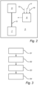
- FIG. 3 is an exemplary method according to an example.
- a first indication 15 of whether or not a driver of the vehicle 1 is present in a driver's seat of the vehicle 1 is received S1.
- a second indication 17 of whether or not the vehicle 1 being in motion is received S2.
- a third indication 19 of whether or not the vehicle 1 is in a towing mode is received S3.
- the indications are received by the parking brake control arrangement 9, which controls S4, when the first indication 15 indicates that the driver is absent from the driver's seat, the second indication 17 indicates that the vehicle 1 is in motion, and the third indication 19 indicates that the vehicle 1 is not in the towing mode, the parking brake of the vehicle 1 from a disengaged state to an engaged state.
- FIG. 4 is an exemplary parking brake system 5 according to an example.
- the parking brake system 5 comprises a flow control device 21.
- the flow control device 21 is connected to the air reservoir arrangement 7 via a first fluid conduit 23 and connected to the air brake chamber 11 via a second fluid conduit 25.
- the flow control device 21 is controllable between a first state in which it allows flow of air from the air reservoir arrangement 7 into the second fluid conduit 25, and a second state in which it allows air from the second fluid conduit 25 to be discharged from the parking brake system.
- the parking brake control arrangement 9 is configured to control the flow control device 21 to the second state when the first indication 15 indicates that the driver is absent from the driver's seat, the second indication 17 indicates that the vehicle 1 is in motion, and the third indication 19 indicates that the vehicle 1 is not in the towing mode.
- the parking brake control arrangement 9 may additionally be configured to control the flow control device 21 to the first state when the first indication 15 indicates that the driver is present in the driver's seat, or the second indication 17 indicates that the vehicle is stationary, or the third indication 19 indicates that the vehicle 1 is in the towing mode.
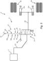
- FIG. 5 is an exemplary parking brake system 5 according to an example.
- the parking brake system 5 is indicated as comprising a first air brake chamber 11a coupled to a first vehicle wheel 3a, and a second air brake chamber 11b coupled to a second vehicle wheel 3b.
- the schematically illustrated air brake chambers 3a-b operate by actuating the brakes of the respective wheels 3a-b when the air pressure inside the respective air brake chambers 11a-b falls below a predefined parking brake threshold pressure.
- the air pressure inside the air brake chambers 11a-b is controlled using a flow control device 21.
- the flow control device 21 is exemplified as comprising a directional control valve 22, a spring 24, and an actuator 41, here in the form of a solenoid.
- the spring 24 urges the directional control valve 22 to the position indicated in FIG. 5 , where the directional control valve 22 connects the air reservoir to the air brake chambers 11a-b, via the first fluid conduit 23 and the second fluid conduit 25, to thereby maintain the pressure inside the air brake chambers 1 1a-b, keeping the parking brakes of the wheels 3a-b disengaged.
- the actuator 41 When the actuator 41 is energized, it pushes the directional control valve 22 away, compressing the spring 24 and connecting the air brake chambers 11a-b to the surroundings via the second fluid conduit, thereby allowing the pressure inside the air brake chambers 11a-b to fall below the parking brake threshold pressure. This results in the air brake chambers 11a-b actuating the brakes of the wheels 3a-b.
- the actuator 41 in this example a solenoid, is energized when the switching arrangement 27 of the parking brake control arrangement 9 connects the actuator 41 to a power source.
- the power source is represented by a first potential V1 and a second potential V2.
- the switching arrangement 27 comprises a first switch 29, a second switch 31, a third switch 33, and a fourth switch 35, all coupled in series between a power source terminal (in this case V1) and the actuator 41.
- Each of the switches is controllable between a non-conducting state and a conducting state, and current can only flow through the actuator when each of the switches is in its conducting state.
- the first switch 29 is controllable from its non-conducting state to its conducting state in response to receiving an indication 15a that the driver is likely not sitting in the driver's seat
- the second switch 31 is controllable from its non-conducting state to its conducting state in response to receiving an indication 15b that the seat belt of the driver's seat is unlocked
- the third switch 33 is controllable from its non-conducting state to its conducting state in response to receiving an indication 17 that the vehicle is in motion
- the fourth switch 35 is controllable from its non-conducting state to its conducting state in response to receiving an indication 19 that the vehicle is not in the towing mode.
- Relative terms such as “below” or “above” or “upper” or “lower” or “horizontal” or “vertical” may be used herein to describe a relationship of one element to another element as illustrated in the Figures. It will be understood that these terms and those discussed above are intended to encompass different orientations of the device in addition to the orientation depicted in the Figures. It will be understood that when an element is referred to as being “connected” or “coupled” to another element, it can be directly connected or coupled to the other element, or intervening elements may be present. In contrast, when an element is referred to as being “directly connected” or “directly coupled” to another element, there are no intervening elements present.
Landscapes
- Engineering & Computer Science (AREA)
- Transportation (AREA)
- Mechanical Engineering (AREA)
- Human Computer Interaction (AREA)
- Regulating Braking Force (AREA)
Abstract
Description
- The disclosure relates generally to vehicle sub-system control. In particular aspects, the disclosure relates to a parking brake control arrangement. The disclosure can be applied to heavy-duty vehicles, such as trucks, buses, and construction equipment, among other vehicle types. Although the disclosure may be described with respect to a particular vehicle, the disclosure is not restricted to any particular vehicle.
- Various vehicles, in particular various heavy duty vehicles, are provided with systems for automatically activating the parking brake if it is determined that the driver is not in the driver's seat.
- It would be desirable to provide for improved automatic activation of the parking brake of a vehicle.
- According to a first aspect of the disclosure, there is provided a parking brake control arrangement for controlling operation of a parking brake of a vehicle, configured to: receive a first indication of whether or not a driver of the vehicle is present in a driver's seat of the vehicle; receive a second indication of whether or not the vehicle being in motion; receive a third indication of whether or not the vehicle is in a towing mode; and control, when the first indication indicates that the driver is absent from the driver's seat, the second indication indicates that the vehicle is in movement, and the third indication indicates that the vehicle is not in the towing mode, the parking brake of the vehicle from a disengaged state to an engaged state. The first aspect of the disclosure may seek to provide for improved automatic activation of the parking brake of a vehicle. A technical benefit may include that automatic activation of the parking brake may be prevented when it has been indicated that the vehicle is to be towed. Hereby, it can be prevented that the parking brake is engaged when towing starts while the driver is not in the driver's seat of the vehicle. This may in turn reduce the risk of vehicle damage resulting from towing.
- Optionally in some examples, including in at least one preferred example, the first indication may indicate that the driver is absent from the driver's seat when a weight sensor in the driver's seat indicates that the driver is likely not sitting in the driver's seat and a seat belt sensor indicates that a seat belt of the driver's seat is unlocked. A technical benefit may include to reduce the risk of an incorrect indication that the driver is absent from the driver's seat, thereby reducing the risk of automatic engagement of the parking brake when the driver is in fact in the seat.
- Optionally in some examples, including in at least one preferred example, the parking brake control arrangement may be configured to: control, when the first indication indicates that the driver is absent from the driver's seat, the second indication indicates that the vehicle is in motion, and the third indication indicates that the vehicle is in the towing mode, the parking brake of the vehicle to be in the disengaged state. A technical benefit may include to allow towing of the vehicle with the driver outside the cabin, without the parking brake being automatically engaged. This may reduce the risk of damage to the vehicle that may otherwise occur due to the parking brake being automatically engaged in response to detecting that the driver is not in the cabin.
- Optionally in some examples, including in at least one preferred example, the parking brake control arrangement may be configured to: control, when the first indication indicates that the driver is present in the driver's seat, or the second indication indicates that the vehicle is stationary, or the third indication indicates that the vehicle is in the towing mode, the parking brake of the vehicle from the engaged state to the disengaged state. A technical benefit may include to provide an improved combination of safety and convenience, by automatically engaging the parking brake, and then automatically disengaging the parking brake when certain conditions are fulfilled. In particular, the parking brake may be automatically disengaged when it is detected that the driver has returned to the cabin, or when it is detected that a towing state has been activated. The towing state may, for example, be activated by manually operating a switch, or by actuation of a detector coupled to a towing interface of the vehicle.
- Optionally in some examples, including in at least one preferred example, the parking brake control arrangement may comprise a switching arrangement controllable to connect a power source to an actuator of the parking brake of the vehicle. A technical benefit may include that this is a reliable way of controlling the automatic engagement of the parking brake of the vehicle.
- Optionally in some examples, including in at least one preferred example, the switching arrangement may comprise a plurality of controllable switches, the switches being arranged to connect the power source to the actuator of the parking brake of the vehicle in response to the first indication indicating that the driver is absent from the driver's seat, the second indication indicating that the vehicle is in motion, and the third indication indicating that the vehicle is not in the towing mode. A technical benefit may include that this is a reliable way of controlling the automatic engagement of the parking brake of the vehicle.
- Optionally in some examples, including in at least one preferred example, parking brake control arrangement may comprise a switching arrangement controllable to connect a power source to an actuator of the parking brake of the vehicle, the switching arrangement including: a first switch controllable from a non-conducting state to a conducting state in response to receiving an indication that the driver is likely not sitting in the driver's seat; a second switch coupled in series with the first switch, and controllable from a non-conducting state to a conducting state in response to receiving an indication that the seat belt of the driver's seat is unlocked; a third switch coupled in series with the first switch and the second switch, and controllable from a non-conducting state to a conducting state in response to receiving the indication that the vehicle is in motion; and a fourth switch coupled in series with the first, second, and third switches, controllable from a non-conducting state to a conducting state in response to receiving the indication that the vehicle is not in the towing mode. A technical benefit may include that this is a reliable and convenient way of controlling the automatic engagement and disengagement of the parking brake of the vehicle, reducing the risk of damage to the vehicle during towing, as compared to vehicles equipped with known systems for automatically engaging the parking brake in response to detecting that the driver has left the cabin.
- Optionally in some examples, including in at least one preferred example, the parking brake control arrangement according to examples of the present disclosure may be included in a parking brake system for a heavy duty vehicle, further comprising: an air reservoir arrangement for storing pressurized air for operation of the parking brake system; an air brake chamber configured to engage a parking brake of the vehicle when an air pressure inside the air brake chamber is lower than a predefined parking brake threshold pressure. The parking brake control arrangement is arranged to control, when the first indication indicates that the driver is absent from the driver's seat, the second indication indicates that the vehicle is in motion, and the third indication indicates that the vehicle is not in the towing mode, the air pressure inside the air brake chamber to become lower than the predefined parking brake threshold pressure.
- Optionally in some examples, including in at least one preferred example, the parking brake system may comprise a flow control device connected to the air reservoir arrangement via a first fluid conduit and connected to the air brake chamber via a second fluid conduit, the flow control device being controllable between a first state in which it allows flow of air from the air reservoir arrangement into the second fluid conduit, and a second state in which it allows air from the second fluid conduit to be discharged from the parking brake system; and the parking brake control arrangement is configured to control the flow control device to the second state when the first indication indicates that the driver is absent from the driver's seat, the second indication indicates that the vehicle is in motion, and the third indication indicates that the vehicle is not in the towing mode.
- Optionally in some examples, including in at least one preferred example, the flow control device may comprise an actuator configured to transition the flow control device from the first state to the second state when the actuator is connected to a power source; and the parking brake control arrangement may comprise a switching arrangement controllable to connect a power source to the actuator of the flow control device.
- Optionally in some examples, including in at least one preferred example, the parking brake control arrangement may comprise a switching arrangement controllable to connect a power source to the actuator of the flow control device, the switching arrangement including: a first switch controllable from a non-conducting state to a conducting state in response to receiving an indication that the driver is likely not sitting in the driver's seat; a second switch coupled in series with the first switch, and controllable from a non-conducting state to a conducting state in response to receiving an indication that the seat belt of the driver's seat is unlocked; a third switch coupled in series with the first switch and the second switch, and controllable from a non-conducting state to a conducting state in response to receiving the indication that the vehicle is in motion; and a fourth switch coupled in series with the first, second, and third switches, and controllable from a non-conducting state to a conducting state in response to receiving the indication that the vehicle is not in the towing mode. A technical benefit may include that this is a reliable and convenient way of controlling the automatic engagement and disengagement of the parking brake of the vehicle, reducing the risk of damage to the vehicle during towing, as compared to vehicles equipped with known systems for automatically engaging the parking brake in response to detecting that the driver has left the cabin.
- Optionally in some examples, including in at least one preferred example, the parking brake system may comprise a power source connected to the switching arrangement of the parking brake control arrangement.
- Optionally in some examples, including in at least one preferred example, the actuator of the flow control device may comprise a solenoid.
- Optionally in some examples, including in at least one preferred example, the parking brake system may be comprised in a vehicle further including vehicle wheels. The parking brake system may be actuatable to brake at least one of the vehicle wheels.
- Optionally in some examples, including in at least one preferred example, the vehicle may comprise an alert system configured to provide an alert external to the vehicle in response to the parking brake control arrangement of the parking brake system controlling the parking brake of the vehicle from the disengaged state to the engaged state. A technical benefit may include that persons in the vicinity of the vehicle may be warned, enabling them to stay out of the way until the vehicle has come to a stop.
- According to a second aspect of the disclosure, there is provided a method of controlling operation of a parking brake of a vehicle, the method comprising: receiving a first indication of whether or not a driver of the vehicle is present in a driver's seat of the vehicle; receiving a second indication of whether or not the vehicle being in motion; receiving a third indication of whether or not the vehicle is in a towing mode; and controlling, when the first indication indicates that the driver is absent from the driver's seat, the second indication indicates that the vehicle is in motion, and the third indication indicates that the vehicle is not in the towing mode, the parking brake of the vehicle from a disengaged state to an engaged state. The second aspect of the disclosure may seek to provide for improved automatic activation of the parking brake of a vehicle. A technical benefit may include that automatic activation of the parking brake may be prevented when it has been indicated that the vehicle is to be towed. Hereby, it can be prevented that the parking brake is engaged when towing starts while the driver is not in the driver's seat of the vehicle. This may in turn reduce the risk of vehicle damage resulting from towing.
- The disclosed aspects, examples (including any preferred examples), and/or accompanying claims may be suitably combined with each other as would be apparent to anyone of ordinary skill in the art. Additional features and advantages are disclosed in the following description, claims, and drawings, and in part will be readily apparent therefrom to those skilled in the art or recognized by practicing the disclosure as described herein.
- Examples are described in more detail below with reference to the appended drawings.
-
FIG. 1 is an exemplary vehicle according to an example. -
FIG. 2 is an exemplary parking brake system according to an example. -
FIG. 3 is an exemplary method according to an example. -
FIG. 4 is an exemplary parking brake system according to an example. -
FIG. 5 is an exemplary parking brake system according to an example. - The detailed description set forth below provides information and examples of the disclosed technology with sufficient detail to enable those skilled in the art to practice the disclosure.
-
FIG. 1 is an exemplary vehicle according to an example. Thevehicle 1, here in the form of a truck, comprises at least one vehicle wheel 3, aparking brake system 5, anair reservoir arrangement 7, and a parkingbrake control arrangement 9. The parkingbrake control arrangement 9 may be considered to be included in theparking brake system 5, and is adapted to control operation of theparking brake system 5. -
FIG. 2 is an exemplaryparking brake system 5 according to an example. Referring toFIG. 2 , the exemplaryparking brake system 5 comprises the above-mentionedair reservoir arrangement 7, the above-mentioned parkingbrake control arrangement 9, anair brake chamber 11, andfluid conduit 13 connecting theair reservoir 7 and theair brake chamber 11. Although not explicitly shown inFIG. 2 , it should be understood that theparking brake system 5 can generally be manually controlled by the driver to allow the driver to engage the parking brake when thevehicle 1 has, for example, been parked. For instance, in the case of a delivery, the driver would normally manually engage the parking brake before leaving the cabin of thevehicle 1 to unload items to be delivered. To address the possibility that the driver may forget to manually engage the parking brake before leaving the cabin of thevehicle 1, it is, per se, known to automatically engage the parking brake when receiving an indication that the driver has left the cabin. - Normally, this condition for automatically engaging the parking brake (that the driver has left the cabin) may be sufficient. The present inventors have, however, realized that the, per se, known automatic engagement of the parking brake when receiving an indication that the driver has left the cabin, has certain drawbacks. In particular, the present inventors have realized that the driver is likely to leave the cabin of a vehicle that is about to be towed, before towing, and that automatic engagement of the parking brake in that situation would be likely to result in serious damage to the vehicle.
- To address this problem, and to provide for a reduced risk of vehicle damage resulting from towing, examples of the parking brake control arrangement according to the present disclosure uses an indication of whether or not the vehicle is in a towing mode as an additional condition for automatic engagement of the parking brake.
- Referring to
FIG. 2 , the parkingbrake control arrangement 9 is configured to receive afirst indication 15, asecond indication 17, and athird indication 19. Thefirst indication 15 indicates whether or not the driver of thevehicle 1 is present in the driver's seat of thevehicle 1, thesecond indication 17 indicates whether or not thevehicle 1 is in motion, and thethird indication 19 indicates whether or not thevehicle 1 is in the above-mentioned towing mode. Thefirst indication 15 may, for example, be a weight indication from a weight sensor (not shown) in the driver's seat, or a seat belt indication from a seat belt switch (not shown), or a logical combination of such indications. Thesecond indication 17 may be an indication from one or more wheel sensors (not shown). Thethird indication 19 may be an indication from a manually operated towing switch (not shown), or an indication that may be provided automatically when thevehicle 1 to be towed is coupled to a tow truck. - The parking
brake control arrangement 9 is configured to control the parking brake of thevehicle 1 from a disengaged state to an engaged state, when thefirst indication 15 indicates that the driver is absent from the driver's seat, thesecond indication 17 indicates that thevehicle 1 is in movement, and thethird indication 19 indicates that thevehicle 1 is not in the towing mode. In the exemplary case ofFIG. 2 , where theparking brake system 5 of thevehicle 1 is an air brake system, the parkingbrake control arrangement 9 may directly control theair brake chamber 11, and/or may control flow of air along at least a portion of thefluid conduit 13 that is connected to theair brake chamber 11. -
FIG. 3 is an exemplary method according to an example. According to the exemplary method, afirst indication 15 of whether or not a driver of thevehicle 1 is present in a driver's seat of thevehicle 1 is received S1. Asecond indication 17 of whether or not thevehicle 1 being in motion is received S2. Athird indication 19 of whether or not thevehicle 1 is in a towing mode is received S3. The indications are received by the parkingbrake control arrangement 9, which controls S4, when thefirst indication 15 indicates that the driver is absent from the driver's seat, thesecond indication 17 indicates that thevehicle 1 is in motion, and thethird indication 19 indicates that thevehicle 1 is not in the towing mode, the parking brake of thevehicle 1 from a disengaged state to an engaged state. -
FIG. 4 is an exemplaryparking brake system 5 according to an example. The difference between the exemplaryparking brake system 5 inFIG. 4 and that inFIG. 2 is that theparking brake system 5 comprises aflow control device 21. As is indicated inFIG. 4 , theflow control device 21 is connected to theair reservoir arrangement 7 via a firstfluid conduit 23 and connected to theair brake chamber 11 via a secondfluid conduit 25. Theflow control device 21 is controllable between a first state in which it allows flow of air from theair reservoir arrangement 7 into the secondfluid conduit 25, and a second state in which it allows air from the secondfluid conduit 25 to be discharged from the parking brake system. - The parking
brake control arrangement 9 is configured to control theflow control device 21 to the second state when thefirst indication 15 indicates that the driver is absent from the driver's seat, thesecond indication 17 indicates that thevehicle 1 is in motion, and thethird indication 19 indicates that thevehicle 1 is not in the towing mode. The parkingbrake control arrangement 9 may additionally be configured to control theflow control device 21 to the first state when thefirst indication 15 indicates that the driver is present in the driver's seat, or thesecond indication 17 indicates that the vehicle is stationary, or thethird indication 19 indicates that thevehicle 1 is in the towing mode. -
FIG. 5 is an exemplaryparking brake system 5 according to an example. InFIG. 5 , theparking brake system 5 is indicated as comprising a firstair brake chamber 11a coupled to afirst vehicle wheel 3a, and a secondair brake chamber 11b coupled to asecond vehicle wheel 3b. As is common in air brake systems, the schematically illustratedair brake chambers 3a-b operate by actuating the brakes of therespective wheels 3a-b when the air pressure inside the respectiveair brake chambers 11a-b falls below a predefined parking brake threshold pressure. The air pressure inside theair brake chambers 11a-b is controlled using aflow control device 21. - In the exemplary parking brake system in
FIG. 5 , theflow control device 21 is exemplified as comprising adirectional control valve 22, aspring 24, and anactuator 41, here in the form of a solenoid. Thespring 24 urges thedirectional control valve 22 to the position indicated inFIG. 5 , where thedirectional control valve 22 connects the air reservoir to theair brake chambers 11a-b, via the firstfluid conduit 23 and the secondfluid conduit 25, to thereby maintain the pressure inside theair brake chambers 1 1a-b, keeping the parking brakes of thewheels 3a-b disengaged. When theactuator 41 is energized, it pushes thedirectional control valve 22 away, compressing thespring 24 and connecting theair brake chambers 11a-b to the surroundings via the second fluid conduit, thereby allowing the pressure inside theair brake chambers 11a-b to fall below the parking brake threshold pressure. This results in theair brake chambers 11a-b actuating the brakes of thewheels 3a-b. - In the example configuration of
FIG. 5 , theactuator 41, in this example a solenoid, is energized when the switchingarrangement 27 of the parkingbrake control arrangement 9 connects theactuator 41 to a power source. InFIG. 5 , the power source is represented by a first potential V1 and a second potential V2. The switchingarrangement 27 comprises afirst switch 29, asecond switch 31, athird switch 33, and afourth switch 35, all coupled in series between a power source terminal (in this case V1) and theactuator 41. Each of the switches is controllable between a non-conducting state and a conducting state, and current can only flow through the actuator when each of the switches is in its conducting state. - In
FIG. 5 , thefirst switch 29 is controllable from its non-conducting state to its conducting state in response to receiving anindication 15a that the driver is likely not sitting in the driver's seat, thesecond switch 31 is controllable from its non-conducting state to its conducting state in response to receiving anindication 15b that the seat belt of the driver's seat is unlocked, thethird switch 33 is controllable from its non-conducting state to its conducting state in response to receiving anindication 17 that the vehicle is in motion, and thefourth switch 35 is controllable from its non-conducting state to its conducting state in response to receiving anindication 19 that the vehicle is not in the towing mode. As is clear from the simplified circuit diagram inFIG. 5 , all of these conditions need to be fulfilled for theactuator 41 to be energized and shift thedirectional control valve 22 to let air out of theair brake chambers 11a-b. When at least one condition is no longer fulfilled, such as if thevehicle 1 is in the towing mode, theactuator 41 will be disconnected from the power source, allowing thespring 24 to shift thedirectional control valve 22 back to the state illustrated inFIG. 5 , where pressurized air from theair reservoir 7 is provided to theair brake chambers 1 1a-b, causing theair brake chambers 11a-b to disengage the brakes of the wheels 3 a-b. - The terminology used herein is for the purpose of describing particular aspects only and is not intended to be limiting of the disclosure. As used herein, the singular forms "a," "an," and "the" are intended to include the plural forms as well, unless the context clearly indicates otherwise. As used herein, the term "and/or" includes any and all combinations of one or more of the associated listed items. It will be further understood that the terms "comprises," "comprising," "includes," and/or "including" when used herein specify the presence of stated features, integers, actions, steps, operations, elements, and/or components, but do not preclude the presence or addition of one or more other features, integers, actions, steps, operations, elements, components, and/or groups thereof.
- It will be understood that, although the terms first, second, etc., may be used herein to describe various elements, these elements should not be limited by these terms. These terms are only used to distinguish one element from another. For example, a first element could be termed a second element, and, similarly, a second element could be termed a first element without departing from the scope of the present disclosure.
- Relative terms such as "below" or "above" or "upper" or "lower" or "horizontal" or "vertical" may be used herein to describe a relationship of one element to another element as illustrated in the Figures. It will be understood that these terms and those discussed above are intended to encompass different orientations of the device in addition to the orientation depicted in the Figures. It will be understood that when an element is referred to as being "connected" or "coupled" to another element, it can be directly connected or coupled to the other element, or intervening elements may be present. In contrast, when an element is referred to as being "directly connected" or "directly coupled" to another element, there are no intervening elements present.
- Unless otherwise defined, all terms (including technical and scientific terms) used herein have the same meaning as commonly understood by one of ordinary skill in the art to which this disclosure belongs. It will be further understood that terms used herein should be interpreted as having a meaning consistent with ∑their meaning in the context of this specification and the relevant art and will not be interpreted in an idealized or overly formal sense unless expressly so defined herein.
- It is to be understood that the present disclosure is not limited to the aspects described above and illustrated in the drawings; rather, the skilled person will recognize that many changes and modifications may be made within the scope of the present disclosure and appended claims. In the drawings and specification, there have been disclosed aspects for purposes of illustration only and not for purposes of limitation, the scope of the disclosure being set forth in the following claims.
Claims (15)
- A parking brake control arrangement (9) for controlling operation of a parking brake (5) of a vehicle (1), configured to:receive a first indication (15) of whether or not a driver of the vehicle (1) is present in a driver's seat of the vehicle (1);receive a second indication (17) of whether or not the vehicle being in motion;receive a third indication (19) of whether or not the vehicle (1) is in a towing mode; andcontrol, when the first indication (15) indicates that the driver is absent from the driver's seat, the second indication (17) indicates that the vehicle (1) is in movement, and the third indication (19) indicates that the vehicle (1) is not in the towing mode, the parking brake (5) of the vehicle (1) from a disengaged state to an engaged state.
- The parking brake control arrangement (9) of claim 1, the first indication (15) indicating that the driver is absent from the driver's seat when a weight sensor in the driver's seat indicates that the driver is likely not sitting in the driver's seat and a seat belt sensor indicates that a seat belt of the driver's seat is unlocked.
- The parking brake control arrangement (9) of claim 1 or 2, the parking brake control arrangement (9) being configured to:
control, when the first indication (15) indicates that the driver is absent from the driver's seat, the second indication (17) indicates that the vehicle (1) is in motion, and the third indication (19) indicates that the vehicle (1) is in the towing mode, the parking brake (5) of the vehicle (1) to be in the disengaged state. - The parking brake control arrangement (9) of any one of claims 1 to 3, the parking brake control arrangement (9) being configured to:
control, when the first indication (15) indicates that the driver is present in the driver's seat, or the second indication (17) indicates that the vehicle (1) is stationary, or the third indication (19) indicates that the vehicle is in the towing mode, the parking brake (5) of the vehicle (1) from the engaged state to the disengaged state. - The parking brake control arrangement (9) of any one of claims 1 to 4, the parking brake control arrangement (9) comprising:
a switching arrangement (27) controllable to connect a power source (37) to an actuator (41) of the parking brake (5) of the vehicle (1). - The parking brake control arrangement (9) of claim 5, the switching arrangement (27) comprising a plurality of controllable switches, the switches being arranged to connect the power source (37) to the actuator (41) of the parking brake (5) of the vehicle (1) in response to the first indication (15) indicating that the driver is absent from the driver's seat, the second indication (17) indicating that the vehicle (1) is in motion, and the third indication (19) indicating that the vehicle (1) is not in the towing mode.
- The parking brake control arrangement (9) of claim 2, the parking brake control arrangement (9) comprising a switching arrangement (27) controllable to connect a power source (37) to an actuator (41) of the parking brake (5) of the vehicle (1), the switching arrangement (27) including:a first switch (29) controllable from a non-conducting state to a conducting state in response to receiving an indication (15a) that the driver is likely not sitting in the driver's seat;a second switch (31) coupled in series with the first switch (29), and controllable from a non-conducting state to a conducting state in response to receiving an indication (15b) that the seat belt of the driver's seat is unlocked;a third switch (33) coupled in series with the first switch (29) and the second switch (31), and controllable from a non-conducting state to a conducting state in response to receiving the indication (17) that the vehicle (1) is in motion; anda fourth switch (35) coupled in series with the first (29), second (31), and third (33) switches, controllable from a non-conducting state to a conducting state in response to receiving the indication (19) that the vehicle (1) is not in the towing mode.
- A parking brake system (5) for a heavy duty vehicle (1), comprising:an air reservoir arrangement (7) for storing pressurized air for operation of the parking brake system (5);an air brake chamber (11) configured to engage a parking brake of the vehicle (1) when an air pressure inside the air brake chamber (11) is lower than a predefined parking brake threshold pressure; andthe parking brake control arrangement (9) of any one of claims 1 to 7 arranged to control, when the first indication (15) indicates that the driver is absent from the driver's seat, the second indication (17) indicates that the vehicle is in motion, and the third indication (19) indicates that the vehicle (1) is not in the towing mode, the air pressure inside the air brake chamber (11) to become lower than the predefined parking brake threshold pressure.
- The parking brake system (5) of claim 8, wherein:the parking brake system (5) comprises a flow control device (21) connected to the air reservoir arrangement (7) via a first fluid conduit (23) and connected to the air brake chamber (11) via a second fluid conduit (25), the flow control device (21) being controllable between a first state in which it allows flow of air from the air reservoir arrangement (7) into the second fluid conduit (25), and a second state in which it allows air from the second fluid conduit (25) to be discharged from the parking brake system (5); andthe parking brake control arrangement (9) is configured to control the flow control device (21) to the second state when the first indication (15) indicates that the driver is absent from the driver's seat, the second indication (17) indicates that the vehicle (1) is in motion, and the third indication (19) indicates that the vehicle (1) is not in the towing mode.
- The parking brake system (5) of claim 9, wherein:the flow control device (21) comprises an actuator (41) configured to transition the flow control device (21) from the first state to the second state when the actuator (41) is connected to a power source (37); andthe parking brake control arrangement (9) comprises a switching arrangement (27) controllable to connect a power source (37) to the actuator (41) of the flow control device (21).
- The parking brake system (5) of claim 10, the parking brake control arrangement (9) comprising a switching arrangement (21) controllable to connect a power source (37) to the actuator (41) of the flow control device (21), the switching arrangement (27) including:a first switch (29) controllable from a non-conducting state to a conducting state in response to receiving an indication (15a) that the driver is likely not sitting in the driver's seat;a second switch (31) coupled in series with the first switch (29), and controllable from a non-conducting state to a conducting state in response to receiving an indication (15b) that the seat belt of the driver's seat is unlocked;a third switch (33) coupled in series with the first switch (29) and the second switch (31), and controllable from a non-conducting state to a conducting state in response to receiving the indication (17) that the vehicle (1) is in motion; anda fourth switch (35) coupled in series with the first (29), second (31), and third (33) switches, and controllable from a non-conducting state to a conducting state in response to receiving the indication (19) that the vehicle (1) is not in the towing mode.
- The parking brake system (5) of claim 10 or 11, comprising a power source (37) connected to the switching arrangement (27) of the parking brake control arrangement (9).
- A vehicle (1) comprising:vehicle wheels (3); andthe parking brake system (5) of any of claims 8 to 13 actuatable to brake at least one of the vehicle wheels (3).
- The vehicle (1) of claim 13, comprising an alert system configured to provide an alert external to the vehicle (1) in response to the parking brake control arrangement (9) of the parking brake system (5) controlling the parking brake of the vehicle (1) from the disengaged state to the engaged state.
- A method of controlling operation of a parking brake (5) of a vehicle (1), the method comprising:receiving (S1) a first indication (15) of whether or not a driver of the vehicle (1) is present in a driver's seat of the vehicle (1);receiving (S2) a second indication (17) of whether or not the vehicle (1) being in motion;receiving (S3) a third indication (19) of whether or not the vehicle (1) is in a towing mode; andcontrolling (S4), when the first indication (15) indicates that the driver is absent from the driver's seat, the second indication (17) indicates that the vehicle (1) is in motion, and the third indication (19) indicates that the vehicle (1) is not in the towing mode, the parking brake (5) of the vehicle (1) from a disengaged state to an engaged state.
Priority Applications (2)
| Application Number | Priority Date | Filing Date | Title |
|---|---|---|---|
| EP23212653.2A EP4563423A1 (en) | 2023-11-28 | 2023-11-28 | Parking brake control arrangement |
| US18/950,018 US20250170994A1 (en) | 2023-11-28 | 2024-11-16 | Parking brake control arrangement |
Applications Claiming Priority (1)
| Application Number | Priority Date | Filing Date | Title |
|---|---|---|---|
| EP23212653.2A EP4563423A1 (en) | 2023-11-28 | 2023-11-28 | Parking brake control arrangement |
Publications (1)
| Publication Number | Publication Date |
|---|---|
| EP4563423A1 true EP4563423A1 (en) | 2025-06-04 |
Family
ID=88978200
Family Applications (1)
| Application Number | Title | Priority Date | Filing Date |
|---|---|---|---|
| EP23212653.2A Pending EP4563423A1 (en) | 2023-11-28 | 2023-11-28 | Parking brake control arrangement |
Country Status (2)
| Country | Link |
|---|---|
| US (1) | US20250170994A1 (en) |
| EP (1) | EP4563423A1 (en) |
Families Citing this family (1)
| Publication number | Priority date | Publication date | Assignee | Title |
|---|---|---|---|---|
| US20260048723A1 (en) * | 2024-08-13 | 2026-02-19 | Volvo Truck Corporation | Computer system for temporarily disabling an automatic application of a parking brake of a vehicle, vehicle comprising such a computer system, method, computer program product and non-transitory computer-readable storage medium |
Citations (3)
| Publication number | Priority date | Publication date | Assignee | Title |
|---|---|---|---|---|
| EP1063453B1 (en) * | 1999-06-25 | 2005-01-26 | Volkswagen Aktiengesellschaft | Control unit for an automatic parking lock of a vehicle |
| US9381895B1 (en) * | 2012-12-07 | 2016-07-05 | Randall H. SMATHERS | Parking brake safety system |
| US20170043752A1 (en) * | 2015-08-13 | 2017-02-16 | Paul H. Stoloff | Electric parking brake control using steering wheel torque to determine driver presence |
-
2023
- 2023-11-28 EP EP23212653.2A patent/EP4563423A1/en active Pending
-
2024
- 2024-11-16 US US18/950,018 patent/US20250170994A1/en active Pending
Patent Citations (3)
| Publication number | Priority date | Publication date | Assignee | Title |
|---|---|---|---|---|
| EP1063453B1 (en) * | 1999-06-25 | 2005-01-26 | Volkswagen Aktiengesellschaft | Control unit for an automatic parking lock of a vehicle |
| US9381895B1 (en) * | 2012-12-07 | 2016-07-05 | Randall H. SMATHERS | Parking brake safety system |
| US20170043752A1 (en) * | 2015-08-13 | 2017-02-16 | Paul H. Stoloff | Electric parking brake control using steering wheel torque to determine driver presence |
Also Published As
| Publication number | Publication date |
|---|---|
| US20250170994A1 (en) | 2025-05-29 |
Similar Documents
| Publication | Publication Date | Title |
|---|---|---|
| US9248817B2 (en) | Anti-rollaway device for trucks and equipment with fluid and electrically actuated brakes | |
| CN116075452B (en) | Commercial vehicle trailer - compressed air system | |
| CN106166993B (en) | Method and device for operating a vehicle capable of autonomous driving | |
| EP2334525B1 (en) | Method for operating a brake system of a work machine and brake system for a work machine | |
| CN115210120A (en) | Method and parking brake device for an autonomously drivable vehicle | |
| US20250170994A1 (en) | Parking brake control arrangement | |
| CN107972656B (en) | Remote start control apparatus and method considering operating state of parking brake | |
| US20110087386A1 (en) | Method for actuating the neutral position in an automatic or automated transmission of a motor vehicle, and corresponding motor vehicle | |
| US20090210124A1 (en) | Method and device for controlling a motor vehicle comprising an electronically controlled brake system with driving dynamics control | |
| US20180251111A1 (en) | Pneumatic Braking Device | |
| EP1945487B1 (en) | Reverse braking system | |
| US6997521B2 (en) | Parking and service brake control system for a vehicle | |
| CN112533805A (en) | Electropneumatic parking brake system with shut-off valve and method for controlling an electronically controlled pneumatic brake system | |
| CN114248738B (en) | Compressed air unit for trailers | |
| CN107472190B (en) | Car remote control lock system | |
| KR20230154045A (en) | Belt retractor units and vehicles equipped with these belt retractor units | |
| US12545338B2 (en) | Tractor fifth wheel safety system and method of using the same | |
| US12145416B2 (en) | Air supply control arrangement for a heavy-duty vehicle comprising a lift axle | |
| EP4431352B1 (en) | A brake release system for a vehicle comprising a parking brake having a brake chamber | |
| US20240101080A1 (en) | System and method for the automatic deployment of a park control valve in an air braking vehicle | |
| US9873413B2 (en) | Parking brake remote actuation | |
| EP4431350A1 (en) | A pneumatic arrangement for a braking system | |
| CN115379972A (en) | Braking system for autonomous vehicle | |
| US20250100520A1 (en) | Pneumatic brake arrangement, vehicle comprising such an arrangement, and method for parking and de-parking such a vehicle | |
| CA2651403A1 (en) | Anti-rollaway device for trucks and equipment with fluid and electrically actuated brakes |
Legal Events
| Date | Code | Title | Description |
|---|---|---|---|
| PUAI | Public reference made under article 153(3) epc to a published international application that has entered the european phase |
Free format text: ORIGINAL CODE: 0009012 |
|
| STAA | Information on the status of an ep patent application or granted ep patent |
Free format text: STATUS: THE APPLICATION HAS BEEN PUBLISHED |
|
| AK | Designated contracting states |
Kind code of ref document: A1 Designated state(s): AL AT BE BG CH CY CZ DE DK EE ES FI FR GB GR HR HU IE IS IT LI LT LU LV MC ME MK MT NL NO PL PT RO RS SE SI SK SM TR |
|
| STAA | Information on the status of an ep patent application or granted ep patent |
Free format text: STATUS: REQUEST FOR EXAMINATION WAS MADE |
|
| 17P | Request for examination filed |
Effective date: 20251110 |
|
| GRAP | Despatch of communication of intention to grant a patent |
Free format text: ORIGINAL CODE: EPIDOSNIGR1 |
|
| STAA | Information on the status of an ep patent application or granted ep patent |
Free format text: STATUS: GRANT OF PATENT IS INTENDED |
|
| RIC1 | Information provided on ipc code assigned before grant |
Ipc: B60T 7/14 20060101AFI20251117BHEP Ipc: B60N 2/00 20060101ALI20251117BHEP Ipc: B60T 7/12 20060101ALI20251117BHEP |
|
| INTG | Intention to grant announced |
Effective date: 20251222 |