EP4563407A1 - Seat cushion structure and child safety seat - Google Patents
Seat cushion structure and child safety seat Download PDFInfo
- Publication number
- EP4563407A1 EP4563407A1 EP24216592.6A EP24216592A EP4563407A1 EP 4563407 A1 EP4563407 A1 EP 4563407A1 EP 24216592 A EP24216592 A EP 24216592A EP 4563407 A1 EP4563407 A1 EP 4563407A1
- Authority
- EP
- European Patent Office
- Prior art keywords
- seat cushion
- child
- seat
- cushion
- thickness
- Prior art date
- Legal status (The legal status is an assumption and is not a legal conclusion. Google has not performed a legal analysis and makes no representation as to the accuracy of the status listed.)
- Pending
Links
Images


Classifications
-
- B—PERFORMING OPERATIONS; TRANSPORTING
- B60—VEHICLES IN GENERAL
- B60N—SEATS SPECIALLY ADAPTED FOR VEHICLES; VEHICLE PASSENGER ACCOMMODATION NOT OTHERWISE PROVIDED FOR
- B60N2/00—Seats specially adapted for vehicles; Arrangement or mounting of seats in vehicles
- B60N2/24—Seats specially adapted for vehicles; Arrangement or mounting of seats in vehicles for particular purposes or particular vehicles
- B60N2/26—Seats specially adapted for vehicles; Arrangement or mounting of seats in vehicles for particular purposes or particular vehicles for children
- B60N2/28—Seats readily mountable on, and dismountable from, existing seats or other parts of the vehicle
- B60N2/2851—Seats readily mountable on, and dismountable from, existing seats or other parts of the vehicle provided with head-rests
-
- B—PERFORMING OPERATIONS; TRANSPORTING
- B60—VEHICLES IN GENERAL
- B60N—SEATS SPECIALLY ADAPTED FOR VEHICLES; VEHICLE PASSENGER ACCOMMODATION NOT OTHERWISE PROVIDED FOR
- B60N2/00—Seats specially adapted for vehicles; Arrangement or mounting of seats in vehicles
- B60N2/24—Seats specially adapted for vehicles; Arrangement or mounting of seats in vehicles for particular purposes or particular vehicles
- B60N2/26—Seats specially adapted for vehicles; Arrangement or mounting of seats in vehicles for particular purposes or particular vehicles for children
- B60N2/28—Seats readily mountable on, and dismountable from, existing seats or other parts of the vehicle
- B60N2/2866—Seats readily mountable on, and dismountable from, existing seats or other parts of the vehicle booster cushions, e.g. to lift a child to allow proper use of the conventional safety belts
-
- B—PERFORMING OPERATIONS; TRANSPORTING
- B60—VEHICLES IN GENERAL
- B60N—SEATS SPECIALLY ADAPTED FOR VEHICLES; VEHICLE PASSENGER ACCOMMODATION NOT OTHERWISE PROVIDED FOR
- B60N2/00—Seats specially adapted for vehicles; Arrangement or mounting of seats in vehicles
- B60N2/24—Seats specially adapted for vehicles; Arrangement or mounting of seats in vehicles for particular purposes or particular vehicles
- B60N2/26—Seats specially adapted for vehicles; Arrangement or mounting of seats in vehicles for particular purposes or particular vehicles for children
- B60N2/28—Seats readily mountable on, and dismountable from, existing seats or other parts of the vehicle
- B60N2/2842—Seats readily mountable on, and dismountable from, existing seats or other parts of the vehicle adapted to carry the child, when dismounted from the vehicle
- B60N2/2845—Seats readily mountable on, and dismountable from, existing seats or other parts of the vehicle adapted to carry the child, when dismounted from the vehicle having handles
-
- B—PERFORMING OPERATIONS; TRANSPORTING
- B60—VEHICLES IN GENERAL
- B60N—SEATS SPECIALLY ADAPTED FOR VEHICLES; VEHICLE PASSENGER ACCOMMODATION NOT OTHERWISE PROVIDED FOR
- B60N2/00—Seats specially adapted for vehicles; Arrangement or mounting of seats in vehicles
- B60N2/24—Seats specially adapted for vehicles; Arrangement or mounting of seats in vehicles for particular purposes or particular vehicles
- B60N2/26—Seats specially adapted for vehicles; Arrangement or mounting of seats in vehicles for particular purposes or particular vehicles for children
- B60N2/28—Seats readily mountable on, and dismountable from, existing seats or other parts of the vehicle
- B60N2/2881—Upholstery, padded or cushioned members therefor
Definitions
- the present disclosure relates to a seat cushion structure and a child safety seat including the seat cushion structure.
- a child safety seat is a device specifically designed for children, which can reduce impact on a child that is restrained in the safety seat during a car riding in the event of a car collision or sudden deceleration, thereby decreasing injuries to the child and effectively improving the riding safety of the child.
- a seat cushion structure is often added to the safety seat, to further support the child's body and improve comfort and safety.
- the present disclosure aims to provide a reliable and safe seat cushion structure and a child safety seat including the seat cushion structure.
- a seat cushion structure is provided and applicable to a seat body of a child safety seat.
- the seat cushion structure includes: a back cushion configured to support a back of a child, the back cushion having a first surface and a second surface opposite to the first surface, the first surface configured to face the child; and a seat cushion configured to support a hip of the child.
- the back cushion is provided with a pushing portion, and the pushing portion makes the first surface of the back cushion push the back of the child, allowing the back and the head of the child tend to be in a same straight line; and/or the seat cushion is provided with a blocking portion configured to block the child from sliding down.
- the pushing portion is on the first surface or the second surface of the back cushion, and an outer surface of the pushing portion forms at least a part of the first surface of the back cushion or at least a part of the second surface of the back cushion.
- the back cushion is integrally made with the pushing portion, and an outer surface of the pushing portion forms at least a part of the second surface of the back cushion.
- the pushing portion is configured as a protrusion protruding in a direction away from the first surface of the seat cushion.
- the pushing portion increases a material thickness of the back cushion at the pushing portion, causing the pushing portion to exhibit a raised shape; or the back cushion has a constant material thickness but is curved and bulged to form a raised shape at the pushing portion.
- the back cushion has a first end and a second end along an up-down direction, and the first end of the back cushion is away from the seat cushion relative to the second end of the back cushion; the back cushion has a first thickness at the first end, a second thickness at the second end, and a third thickness at the pushing portion, the third thickness being greater than the second thickness.
- the third thickness is greater than the first thickness.
- the pushing portion is in a middle position between the first end and the second end of the back cushion, and extends at least a part of a left-right width of the back cushion along a left-right direction of the back cushion.
- the back cushion is provided with a ventilation hole extending from the first surface to the second surface of the back cushion.
- the seat cushion has a first end and a second end opposite to the first end; the first end of the seat cushion is connected to a second end of the back cushion through an arc-shaped transition; and the second end of the seat cushion extends forward and upward.
- the seat cushion and the back cushion are integrally made.
- the seat cushion has a first surface and a second surface opposite to the first surface, and the first surface of the seat cushion is configured to face the child; and the first surface of the seat cushion and the second surface of the seat cushion are inclined forward and upward, and a distance between the first surface of the seat cushion and the second surface of the seat cushion gradually increases in a forward and upward direction.
- a first angle is formed between a connection line of the first surface of the seat cushion and a connection line of the second surface of the seat cushion, and the first angle is not less than 8° and not greater than 25°.
- the first angle is 11°.
- the seat cushion has a first surface and a second surface opposite to the first surface, and the first surface of the seat cushion is configured to face the child; and a second angle is formed between a connection line of the first surface of the back cushion and a connection line of the first surface of the seat cushion, and the second angle is not less than 101° and not greater than 110°.
- the second angle is 105°.
- the seat cushion also has a third surface at the second end of the seat cushion, and the third surface connects the first surface of the seat cushion with the second surface of the seat cushion.
- the second surface of the seat cushion extends forward and upward beyond the first surface, and the third surface is connected to the first surface through an arc-shaped transition.
- the blocking portion is in the form of a protrusion extending forward and upward, and an outer surface of the blocking portion forms at least a part of the first surface of the seat cushion and forms the third surface of the seat cushion.
- a thickness of the back cushion at the second end is a second thickness
- a thickness between an end of the straight segment close to the arc segment and a second surface of the seat cushion is a fourth thickness, which is greater than the second thickness
- a thickness between the first surface of the seat cushion and the second surface of the seat cushion and adjacent to the third surface of the seat cushion is a fifth thickness, which is greater than the fourth thickness.
- the seat cushion is provided with an avoidance portion configured to avoid a crotch belt assembly arranged on a seating portion of the seat body.
- the avoidance portion is in the form of an avoidance notch recessed rearward from the third surface of the seat cushion, and the avoidance notch has an avoidance portion limiting surface.
- the avoidance portion limiting surface is perpendicular to the second surface of the seat cushion or extends obliquely from front to rear and from top to bottom relative to the second surface of the seat cushion.
- a child safety seat including a seat body and a support structure arranged on the seat body.
- the support structure includes: a headrest configured to support a head of a child; and the seat cushion structure described above.
- the headrest has a first end and a second end in an upper and down direction, and the first end of the headrest is away from the seat cushion structure relative to the second end of the headrest.
- An upper protrusion is provided at the first end of the headrest; and/or a side protrusion is provided at each of left and right sides of the headrest.
- the headrest has a first surface and a second surface opposite to the first surface, and the first surface is configured to face the child; a transition portion is provided at the second end of the headrest and is bent downwardly toward the second surface of the headrest relative to other portions of the headrest.
- a thickness of the headrest at the transition portion is a sixth thickness, which is less than a first thickness of the back cushion at a first end of the back cushion away from the seat cushion.
- a third angle is formed between a second surface of the seat cushion and the horizontal plane and is not less than 25° and not greater than 55°.
- the third angle is 40°.
- a child safety seat including a seat body; and a seat cushion structure, removably arranged on the seat body and including a back cushion and a seat cushion, the seat cushion having a first surface configured to face a child.
- a fourth angle is formed between a first surface of the seat cushion and the horizontal plane and is not less than 33° and not greater than 80°.
- the fourth angle is not less than 36° and not greater than 70°.
- the fourth angle is 51°.
- the seat cushion structure according to the present disclosure can effectively prevent the child sitting thereon from losing protection of the headrest due to downward sliding of the child's body, and can provide effective and safe support for the child, so that the head and body of the child are in a straight line, avoiding danger caused by the child's head bending toward the child's body, to provide reliable and safe support for the child.
- the seat body 12 may be divided into a backrest and a seat.
- the child safety seat 10 is detachably mounted on the car seat.
- the child safety seat 10 typically includes a handle 14 that spans both end sides of the seat body 12 in a width direction.
- the child safety seat 10 as shown in FIG. 1 is in the form of a basket, which may be mounted on the car seat or the child stroller for use, or may be lifted for separate use.
- the child safety seat 10 also has a crotch belt assembly 16 that is connected to the seat of the seat body 12.
- the crotch belt assembly 16 includes a crotch belt and a buckle connected to the crotch belt.
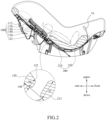
- FIG. 2 illustrates a side view of a support structure 20 according to the present disclosure
- the child safety seat 10 includes the support structure 20.
- the support structure 20 includes a headrest 100 and a seat cushion structure 200.
- the headrest 100 is configured to support a child's head.
- the seat cushion structure 200 is detachably arranged on the seat body 12 of the child safety seat 10 and configured to support the child's back and hip.
- the seat cushion structure 200 may further support legs (e.g., thighs) of the child.
- the seat cushion structure 200 can provide better support for young and small-sized children.
- FIG. 2 also schematically illustrates that the child is supported by the support structure 20, with the head resting on the headrest 100 and the back and hip resting on the seat cushion structure 200, and the head and the back are substantially in a same straight line 1.
- the headrest 100 is movable longitudinally along the backrest of the seat body 12 to adjust a height position of the headrest 100.
- the headrest 100 has a first surface 130 and a second surface 140 opposite to the first surface 130.
- the first surface 130 is configured to face the child's head.
- the headrest 100 has a first end 110 and a second end 120.
- the first end 110 of the headrest 100 is away from the seat cushion structure 200 relative to the second end 120 of the headrest.
- the second end 120 of the headrest 100 is close to the seat cushion structure 200 relative to the first end 110 of the headrest 100, and the first end 110 is provided with an upper protrusion 112.
- a side protrusion 113 (as shown in FIG.
- a transition portion 122 is also provided at the second end 120 of the headrest 100 and is bent downwardly toward the second surface 140 relative to other portions of the headrest 100.
- a downward bent part of the transition portion 122 may be a downward arc segment, or may be a downward inclined surface, or may be other downward curved or bent segments.
- the seat cushion structure 200 has a certain degree of hardness to provide sufficient support for children, and the seat cushion structure 200 may, for example, be made of PU foam or EVA foam.
- the seat cushion structure 200 may be arranged inside an outer cloth cover (not shown).
- the outer cloth cover covers outside of the seat cushion structure 200, and the seat cushion structure is kept inside the outer cloth cover by a zipper, a Velcro tape, a buckle, a magnetic buckle, a loop or the like, facilitating replacement and cleaning of the outer cloth cover.
- the outer cloth cover is relatively soft and skin-friendly, and may be made of materials such as Uli fabric or knitted fabric.
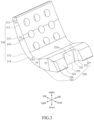
- FIG. 3 is a schematic view of the seat cushion structure 200 according to the present disclosure
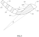
- FIG. 4 is a side view of the seat cushion structure 200 according to the present disclosure
- FIG. 5 shows a side sectional view of the seat cushion structure 200 according to the present disclosure.
- the seat cushion structure 200 includes a back cushion 210 and a seat cushion 220.
- the back cushion 210 supports the child's back, while the seat cushion 220 supports the child's hip or supports the child's hip and legs (such as thighs).
- the back cushion 210 has a first end 213 and a second end 214, and the first end 213 of the back cushion 210 is away from the seat cushion 220 relative to the second end 214 of the back cushion 210.
- a first surface 211 of the back cushion 210 is a surface configured to face the child
- a second surface 212 of the back cushion 210 is a surface configured to face away from the child.
- At least one of the first surface 211 and the second surface 212 of the back cushion 210 is provided with a pushing portion 215.
- the pushing portion 215 can prop up the back cushion 210 after the seat cushion structure 200 is placed on the child safety seat 10, so that the child's back can be better propped up, and the head and back of the child can be relatively stretched, preventing the child's head from bending toward the child's back and affecting the child's breathing.
- the pushing portion 215 may be in a middle area of the back cushion 210 in a length direction, or at other positions between the first end 213 of the back cushion 210 and the second end 214 of the back cushion 210.
- the pushing portion 215 extends at least a part of a left-right width of the back cushion 210 along a left-right direction of the back cushion 210.
- the pushing portion 215 is arranged at a side of the back cushion 210 facing away from the first surface 211, that is, the pushing portion 215 is at the second surface 212 of the back cushion 210, and an outer surface of the pushing portion 215 forms at least a part of the second surface 212 of the back cushion 210. Consequently, the pushing portion 215 can abut against the backrest of the child safety seat or the stroller, and meanwhile can prop up (push up) the first surface 211 of the back cushion 210 against the child's back.
- the pushing portion 215 protrudes in an arc shape, so that the second surface 212 of the back cushion 210 overall has an arc shape, and an approximately middle part of the arc shape further protrudes toward the backrest of the child safety seat or the stroller.
- the back cushion 210 may be integrally made with the pushing portion 215, and the pushing portion 215 protrudes in a direction away from the first surface 211.
- the pushing portion 215 is certainly not limited to the arc shape mentioned above.
- the pushing portion in other forms, for example in the form of a bump, is also feasible as long as it can prop up the child's back and reduce an angle at which the child's head bends toward the child's body.
- the pushing portion 215 may not be formed by integral made of the back cushion 210.
- a base of the back cushion 210 and the pushing portion 215 are separately made, and then the pushing portion 215 is bonded to the base by gluing, clamping, or binding, such that the base and the pushing portion together form the back cushion 210.
- the pushing portion 215 is substantially distributed in the middle area of the second surface 212 of the back cushion 210, so that the outer surface of the pushing portion 215 forms a part of the second surface 212 of the back cushion 210.
- the outer surface of the pushing portion 215 may form the entire second surface 212 of the back cushion 210.
- the pushing portion 215 is located at the first surface 211 of the back cushion 210, and the outer surface of the pushing portion 215 forms at least a part of the first surface 211 of the back cushion 210, which can prop up the first surface 211 of the back cushion 210 against the child's back.
- FIG. 4 shows that the back cushion 210 has a first thickness T1 at the first end 213 and a second thickness T2 at the second end 214, while the back cushion 210 has a third thickness T3 at the pushing portion 215, in which the third thickness T3 is greater than the second thickness T2 and also greater than the first thickness T1.
- the pushing portion 215 in this embodiment increases the material thickness of the back cushion 210 at the pushing portion 215, causing the pushing portion 215 to exhibit a raised shape, so that the first surface 211 of the back cushion 210 can push the child's back forward and upward.
- the pushing portion 215 in this embodiment may also be called a back thickening portion.
- the child's back may be propped up by a curved shape of the pushing portion 215; for example, the material thickness remains unchanged, but the pushing portion 215 is curved and bulged to form the raised shape.
- the arrangement of the pushing portion 215 can make the child's back more stretched, thereby leading to more stretch between the head and the back, avoiding excessive inward bending of the child's back, and facilitating smooth breathing of the child. It should be noted that in other embodiments, the pushing portion 215 may not be raised, as long as it can push up the child's back, so that the back and head of the child tend to be in the same straight line.
- the back cushion 210 is also provided with a ventilation hole 216.
- a ventilation hole 216 There may be a plurality of ventilation holes 216 extending from the first surface 211 to the second surface 212 of the back cushion 210.
- the ventilation holes 216 shown in the figure are circular. However, in other embodiments, the ventilation holes 216 may also be designed in other shapes, such as elliptical, runway-shaped, strip-shaped, square, rectangular, etc.
- the back cushion 210 and the seat cushion 220 are integrally made; a first end 223 of the seat cushion 220 and the second end 214 of the back cushion 210 are connected as a whole, and the connection is smooth and curved.
- the back cushion 210 and the seat cushion 220 which are integrally made, are arranged at an angle to each other. To achieve optimal riding comfort, the connection between the back cushion 210 and the seat cushion 220 is curved.
- the back cushion 210 and the seat cushion 220 may also be separately made and combined with each other.
- the seat cushion 220 has the first end 223 and a second end 224 opposite to the first end.
- the first end 223 of the seat cushion 220 is connected to the second end 214 of the back cushion 210 through an arc-shaped transition, and the second end 224 of the seat cushion 220 extends forward and upward.
- the seat cushion 220 has a first surface 221 and a second surface 222 opposite to the first surface 221, and the first surface 221 is configured to face the child.
- the first surface 221 of the seat cushion 220 includes an arc segment 221a connected to the second end 214 of the back cushion 210 and a straight segment 221b connected to the arc segment 221a, the straight segment 221b extending substantially straight forward and upward.
- the seat cushion 220 also has a third surface 227 at the second end 224 of the seat cushion 220, and the third surface 227 connects the first surface 221 of the seat cushion 210 with the second surface 222 of the seat cushion 210. As shown in FIGS. 3 and 5 , the third surface 227 and the first surface 221 are connected to each other through an arc-shaped transition.
- the seat cushion 220 also has a blocking portion 226, and the blocking portion 226 can block downward sliding of the sitting child, so that the seat cushion 220 can support the child, help maintain the position of the child's head, and prevent the child from sliding down during sleep or vehicle bumps and hence prevent the child's head from excessively bending toward the back.
- the seat cushion 220 is formed as a whole by integral made.
- the seat cushion 220 may also include a plurality of separate parts, with the blocking portion 226 molded separately from other parts and connected together with each other to collectively form the seat cushion 220.
- the blocking portion 226 is located at the second end 224 of the seat cushion 220 and is in the form of a protrusion extending diagonally upward.
- the blocking portion 226 is located diagonally above the seat cushion 220, and an outer surface of the blocking portion 226 forms at least a part of the first surface 221 of the seat cushion 220 and forms the third surface 227 of the seat cushion 220. Due to the arc-shaped transition between the first surface 221 and the third surface 227, legs (e.g., lower legs) of the child who is elder or has a larger body size can rest against the third surface 227 for comfortable support. A thickness between the first surface 221 and the second surface 222 of the seat cushion 220 gradually increases from the first end 223 of the seat cushion 220 toward an end adjacent to the third surface 227 of the seat cushion 220.
- the first end 223 of the seat cushion 220 is integrally connected to the second end 214 of the back cushion 210.
- a thickness of the seat cushion 220 at its first end 223, i.e., a thickness between an end (close to the back cushion 210) of the arc segment 221a of the first surface 221 of the seat cushion 220 and the second surface 222 of the seat cushion 220 is the second thickness T2 of the back cushion 210 at its second end 214.
- a thickness between an end (close to the arc segment 221a) of the straight segment 221b of the first surface 221 of the seat cushion 220 and the second surface 222 of the seat cushion 220 is a fourth thickness T4, which is greater than the second thickness T2.
- a thickness between the first surface 221 and the second surface 222 of the seat cushion 220 and adjacent to its third surface 227 is a fifth thickness T5, which is greater than the fourth thickness T4.
- a maximum thickness of the seat cushion 220 is the fifth thickness T5 mentioned above.
- a thickness between the straight segment 221b of the first surface 221 and the second surface 222 also gradually increases from an end close to the back cushion 210 to an end close to the third surface 227.
- the second surface 222 of the seat cushion 210 extends forward and upward beyond the first surface 221, and the third surface 227 forms an inclined surface with an arc-shaped transition and connects the first surface 221 with the second surface 222.
- FIG. 6 is a partially side view of the seat cushion 220 according to the present disclosure.
- connection line of the first surface 221 of the seat cushion 220 i.e., a part of the outer surface of the blocking portion 226 in this embodiment
- the above settings of the blocking portion 226 can also provide better support for the child thereon, improving the comfort, stability, and safety of the ride.
- the first surface 221 of the seat cushion 220 and the second surface 222 of the seat cushion 220 both have an arc-shaped transition;
- the first angle ⁇ may be defined by an extension line (i.e., the connection line) of the first surface 221 of the seat cushion 220 and an extension line (i.e., the connection line) of the second surface 222 of the seat cushion 220;
- the second angle ⁇ may be defined by the extension line (i.e., the connection line) of the first surface 221 of the seat cushion 220 and an extension line (i.e., the connection line) of the first surface 211 of the back cushion 210.
- the bottom of the seat body 12 is arc-shaped.
- the horizontal plane is substantially tangent to the bottom of the seat body 12, and the third angle ⁇ may be defined by the extension line of the second surface 222 of the seat cushion 220 and a tangent line of the bottom of the seat body 12.
- the back cushion 210 and the seat cushion 220 may not be connected through any arc-shaped transition but rather may be directly and straightly connected, forming a clear angle origin, in which case the first angle ⁇ may be directly obtained.
- the second angle ⁇ , the third angle ⁇ , and the fourth angle ⁇ may be directly defined without need for extension lines, based on specific shape changes of the seat cushion structure 200 and the bottom of the seat body 12.
- the blocking portion 226 is substantially distributed in a front area of the first surface 221 of the seat cushion 220, such that the outer surface of the blocking portion 226 forms a part of the first surface 221 of the seat cushion 220 (e.g., the straight segment 221b of the first surface 221 of the seat cushion 220) and the third surface 227.
- the outer surface of the blocking portion 226 may form the entire first surface 221 of the seat cushion 220 and/or the third surface 227 of the seat cushion 220.
- the second end 224 of the seat cushion 220 is provided with an avoidance portion 225 to avoid the crotch belt assembly 16 arranged on a seating portion of the seat body 12.
- the avoidance portion 225 may be in the form of an avoidance notch, recessed inward from the third surface 227 of the seat cushion 220, as shown in FIGS. 3 and 5 .
- the avoidance portion 225 may also be in the form of an avoidance hole.
- the crotch belt assembly 16 passes through the avoidance portion 225, the crotch belt assembly 16 can limit and block the seat cushion structure 200, preventing it from sliding down. As a result, cooperation between the avoidance portion 225 and the crotch belt assembly 16 enable the seat cushion structure 200 to better support the child and reduce the risk of downward slide of the child.
- the avoidance portion 225 is an avoidance notch, and an avoidance portion limiting surface 225a is substantially perpendicular to the second surface 222 of the seat cushion 220.
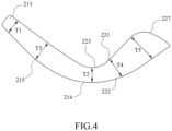
- FIG. 7 which is a partially sectional view of another embodiment of the avoidance portion 225 according to the present disclosure, the avoidance portion limiting surface 225a in this embodiment is inclined downward and inward (i.e., inclined from front to rear and from top to bottom).
- a direction of force exerted by the crotch belt on the avoidance portion limiting surface 225a can tend to be further toward the headrest 100, which facilitates support for the seat cushion structure 200 and prevents the seat cushion structure 200 from sliding down.
- the headrest 100 and the seat cushion structure 200 as described above can provide overall support for the child's body, allowing the child's back and head to stretch relatively (i.e., the back and the head tend to stretch in a straight line, instead of the head bending excessively toward the back), and ensuring smooth breathing of the child.
- the thickness of the back cushion 210 at the first end 213 is the first thickness T1
- a thickness of the headrest 100 at the transition portion 122 is a sixth thickness T6, in which the first thickness T1 is greater than the sixth thickness T6. Consequently, even if the child's head is located at a lower position of the headrest 100, the child's back can still be supported upward relative to the head.
- the head When the child's back is supported upward, the head is driven to stretch away from the back, which in turn allows the child's head resting against the headrest 100 and the child's back resting against the back cushion 210 to be substantially in the same straight line, with a smooth transition between the head and the back, reducing the suffocation risk of the child.
- the first thickness T1 is smaller than the fifth thickness T5 mentioned above (as shown in FIG. 4 ).
- the thickness at each position of the seat cushion structure 200 described above is based on a direction of a support force provided by the seat cushion structure 200 at that position as a thickness direction.
- the thickness direction at each position will vary when the shape of the seat cushion structure 200 is curved.
- thickness directions of the first thickness T1 and the second thickness T2 are not parallel in FIGS. 3 , 4 , and 5 .
- the seat cushion structure 200 when the seat cushion structure 200 cooperates with the seat body 12 in such a way as to enable the first surface 221 of the seat cushion 220 to be inclined at a certain angle with respect to the horizontal plane of the bottom of the seat body 12, the child sits on the seat cushion 220 and is supported by the first surface 221 of a certain inclination, which can also serve to block the child from sliding down.
- an inner surface of the seating portion of the seat body i.e., a surface in contact with the second surface of the seat cushion
- the seat cushion structure 200 is arranged in the seat body 12.
- the angle between the first surface 221 of the seat cushion 220 and the horizontal plane is the aforementioned fourth angle ⁇ , which is not less than 33° and not greater than 80° (i.e., 33° ⁇ ⁇ ⁇ 80°).
- the headrest 100 and the seat cushion structure 200 are separately molded; the headrest 100 is connected to the backrest of the child safety seat 10 and is adjustable in position relative to the backrest; and the seat cushion structure 200 is separately placed in the seat body 12.
- the headrest 100 and the seat cushion structure 200 may both be detachable structures independent of the seat body 12.
- the headrest 100 and the seat cushion structure 200 may be accommodated in different spaces of a same outer cloth cover, allowing the support structure 20 to be detachably placed inside the seat body 12.
- the headrest 100 and the seat cushion structure 200 may be separately accommodated in different outer cloth covers, and then connected together through structures such as a Velcro, a snap fastener, or a zipper.
- the headrest 100 and the seat cushion structure 200 may be integrally molded.
- FIG. 8 is a schematic view of a seat cushion structure 200' according to a comparative embodiment
- FIG. 9 is a schematic view of a support structure 20' according to a comparative embodiment.
- the seat cushion structure 200' is not provided with any pushing portion or any blocking portion, and a surface of the seat cushion structure 200' facing the child tends to be smooth as a whole; and the headrest 100' is not provided with any transition portion. Consequently, when the child is sleeping or the child safety seat bumps with the car movement, the child is very easy to slide down, and the child's head also moves down at the same time, so that as shown in FIG. 9 , the child's head bends toward the back, which can easily affect breathing smoothness of the child.
- the headrest 100 can support the child's head
- the seat cushion structure 200 can support the child's back and hip.
- the second end 120 of the headrest 100 is provided with the transition portion 122
- the back cushion 210 of the seat cushion structure 200 is provided with the pushing portion 215, so that the support structure 20 overall can better support the child's body, making the head and body tend to stretch, substantially in a straight line, and avoiding the risk of suffocation caused by the head bending toward the back.
- the seat cushion 220 of the seat cushion structure 200 is provided with the blocking portion 226, which can limit and block the child, prevent the child from sliding down, and provide more comfortable and safe support for the child sitting thereon.
- the avoidance portion 225 of the seat cushion 220 of the seat cushion structure 200 can allow the crotch belt assembly 16 of the child safety seat 10 to pass through, in order to position the seat cushion structure 200 and further prevent the child from sliding down, thereby providing safe, comfortable, and reliable support for the child.
- a distribution range of the pushing portion in the back cushion may be set to correspond to the movement range of the child's back, so that the head and body of the child always tend to stretch (i.e., when the child lies down normally and slides down, the head and body can both tend to stretch), substantially in the straight line.
- the distribution range of the pushing portion in the back cushion in the present disclosure may only correspond to a range where the child's back is after sliding down.
Landscapes
- Engineering & Computer Science (AREA)
- Health & Medical Sciences (AREA)
- Child & Adolescent Psychology (AREA)
- General Health & Medical Sciences (AREA)
- Aviation & Aerospace Engineering (AREA)
- Transportation (AREA)
- Mechanical Engineering (AREA)
- Seats For Vehicles (AREA)
Abstract
A seat cushion structure (200) and a child safety seat (10) are provided. The seat cushion structure (200) is applicable to a seat body (12) of the child safety seat (10). The seat cushion structure (200) includes: a back cushion (210) configured to support a back of a child and having a first surface (211) configured to face the child and a second surface (212) opposite to the first surface (211); and a seat cushion (220) configured to support a hip of the child. The back cushion (210) is provided with a pushing portion (215), and the pushing portion (215) makes the first surface (211) of the back cushion (210) push the back of the child, allowing the back and the head of the child tend to be in a same straight line; and/or the seat cushion (220) is provided with a blocking portion (226) configured to block the child from sliding down. The seat cushion structure (200) according to the present disclosure can provide efficient and safe support for the child, make the child's head and body keep a stretched state, and avoid danger caused by the child's head bending toward the child's body, to provide the child with safe support.
Description
- The present disclosure relates to a seat cushion structure and a child safety seat including the seat cushion structure.
- A child safety seat is a device specifically designed for children, which can reduce impact on a child that is restrained in the safety seat during a car riding in the event of a car collision or sudden deceleration, thereby decreasing injuries to the child and effectively improving the riding safety of the child.
- For children who are younger or have a smaller body size, a seat cushion structure is often added to the safety seat, to further support the child's body and improve comfort and safety.
- However, there are irrationalities in the design of existing seat cushion structures, so that the child's body is prone to sliding down during the riding, causing the child's head to separate from safety protection of a headrest unit. Moreover, due to an unreasonable angle design of the existing seat cushion structures, the child's head may bend toward the body when sliding occurs, and there is a risk of suffocation when the child's chin touches the child's chest for a long time. Consequently, the existing seat cushion structures cannot provide comfortable, reliable, and safe support for children.
- Accordingly, the present disclosure aims to provide a reliable and safe seat cushion structure and a child safety seat including the seat cushion structure.
- To this end, according to a technical solution of the present disclosure, a seat cushion structure is provided and applicable to a seat body of a child safety seat. The seat cushion structure includes: a back cushion configured to support a back of a child, the back cushion having a first surface and a second surface opposite to the first surface, the first surface configured to face the child; and a seat cushion configured to support a hip of the child. The back cushion is provided with a pushing portion, and the pushing portion makes the first surface of the back cushion push the back of the child, allowing the back and the head of the child tend to be in a same straight line; and/or the seat cushion is provided with a blocking portion configured to block the child from sliding down.
- According to an embodiment, the pushing portion is on the first surface or the second surface of the back cushion, and an outer surface of the pushing portion forms at least a part of the first surface of the back cushion or at least a part of the second surface of the back cushion.
- According to an embodiment, the back cushion is integrally made with the pushing portion, and an outer surface of the pushing portion forms at least a part of the second surface of the back cushion.
- According to an embodiment, the pushing portion is configured as a protrusion protruding in a direction away from the first surface of the seat cushion.
- According to an embodiment, the pushing portion increases a material thickness of the back cushion at the pushing portion, causing the pushing portion to exhibit a raised shape; or the back cushion has a constant material thickness but is curved and bulged to form a raised shape at the pushing portion.
- According to an embodiment, the back cushion has a first end and a second end along an up-down direction, and the first end of the back cushion is away from the seat cushion relative to the second end of the back cushion; the back cushion has a first thickness at the first end, a second thickness at the second end, and a third thickness at the pushing portion, the third thickness being greater than the second thickness.
- According to an embodiment, the third thickness is greater than the first thickness.
- According to an embodiment, the pushing portion is in a middle position between the first end and the second end of the back cushion, and extends at least a part of a left-right width of the back cushion along a left-right direction of the back cushion.
- According to an embodiment, the back cushion is provided with a ventilation hole extending from the first surface to the second surface of the back cushion.
- According to an embodiment, the seat cushion has a first end and a second end opposite to the first end; the first end of the seat cushion is connected to a second end of the back cushion through an arc-shaped transition; and the second end of the seat cushion extends forward and upward.
- According to an embodiment, the seat cushion and the back cushion are integrally made.
- According to an embodiment, the seat cushion has a first surface and a second surface opposite to the first surface, and the first surface of the seat cushion is configured to face the child; and the first surface of the seat cushion includes an arc segment connected to the second end of the back cushion and a straight segment connected to the arc segment.
- According to an embodiment, the seat cushion has a first surface and a second surface opposite to the first surface, and the first surface of the seat cushion is configured to face the child; and the first surface of the seat cushion and the second surface of the seat cushion are inclined forward and upward, and a distance between the first surface of the seat cushion and the second surface of the seat cushion gradually increases in a forward and upward direction.
- According to an embodiment, a first angle is formed between a connection line of the first surface of the seat cushion and a connection line of the second surface of the seat cushion, and the first angle is not less than 8° and not greater than 25°.
- According to an embodiment, the first angle is 11°.
- According to an embodiment, the seat cushion has a first surface and a second surface opposite to the first surface, and the first surface of the seat cushion is configured to face the child; and a second angle is formed between a connection line of the first surface of the back cushion and a connection line of the first surface of the seat cushion, and the second angle is not less than 101° and not greater than 110°.
- According to an embodiment, the second angle is 105°.
- According to an embodiment, the seat cushion also has a third surface at the second end of the seat cushion, and the third surface connects the first surface of the seat cushion with the second surface of the seat cushion.
- According to an embodiment, the second surface of the seat cushion extends forward and upward beyond the first surface, and the third surface is connected to the first surface through an arc-shaped transition.
- According to an embodiment, the blocking portion is in the form of a protrusion extending forward and upward, and an outer surface of the blocking portion forms at least a part of the first surface of the seat cushion and forms the third surface of the seat cushion.
- According to an embodiment, a thickness of the back cushion at the second end is a second thickness, and a thickness between an end of the straight segment close to the arc segment and a second surface of the seat cushion is a fourth thickness, which is greater than the second thickness.
- According to an embodiment, a thickness between the first surface of the seat cushion and the second surface of the seat cushion and adjacent to the third surface of the seat cushion is a fifth thickness, which is greater than the fourth thickness.
- According to an embodiment, the seat cushion is provided with an avoidance portion configured to avoid a crotch belt assembly arranged on a seating portion of the seat body.
- According to an embodiment, the avoidance portion is in the form of an avoidance notch recessed rearward from the third surface of the seat cushion, and the avoidance notch has an avoidance portion limiting surface. The avoidance portion limiting surface is perpendicular to the second surface of the seat cushion or extends obliquely from front to rear and from top to bottom relative to the second surface of the seat cushion.
- According to another aspect of the present disclosure, a child safety seat is provided, including a seat body and a support structure arranged on the seat body. The support structure includes: a headrest configured to support a head of a child; and the seat cushion structure described above.
- According to an embodiment, the headrest has a first end and a second end in an upper and down direction, and the first end of the headrest is away from the seat cushion structure relative to the second end of the headrest. An upper protrusion is provided at the first end of the headrest; and/or a side protrusion is provided at each of left and right sides of the headrest.
- According to an embodiment, the headrest has a first surface and a second surface opposite to the first surface, and the first surface is configured to face the child; a transition portion is provided at the second end of the headrest and is bent downwardly toward the second surface of the headrest relative to other portions of the headrest.
- According to an embodiment, a thickness of the headrest at the transition portion is a sixth thickness, which is less than a first thickness of the back cushion at a first end of the back cushion away from the seat cushion.
- According to an embodiment, when a bottom of the seat body is placed on a horizontal plane, a third angle is formed between a second surface of the seat cushion and the horizontal plane and is not less than 25° and not greater than 55°.
- According to an embodiment, the third angle is 40°.
- According to still another aspect of the present disclosure, a child safety seat is provided, including a seat body; and a seat cushion structure, removably arranged on the seat body and including a back cushion and a seat cushion, the seat cushion having a first surface configured to face a child. When a bottom of the seat body is placed on a horizontal plane, a fourth angle is formed between a first surface of the seat cushion and the horizontal plane and is not less than 33° and not greater than 80°.
- According to an embodiment, the fourth angle is not less than 36° and not greater than 70°.
- According to an embodiment, the fourth angle is 51°.
- The seat cushion structure according to the present disclosure can effectively prevent the child sitting thereon from losing protection of the headrest due to downward sliding of the child's body, and can provide effective and safe support for the child, so that the head and body of the child are in a straight line, avoiding danger caused by the child's head bending toward the child's body, to provide reliable and safe support for the child.
- The accompanying drawings are included herein to provide further understanding of the present disclosure, and are incorporated into and constitute a part of this specification. The drawings illustrate embodiments of the present disclosure and, together with the following description, serve to explain principles of the present disclosure.
- In the drawings:
-
FIG. 1 is a schematic view of a child safety seat according to the present disclosure; -
FIG. 2 illustrates a side view and a partially enlarged view of a support structure according to the present disclosure; -
FIG. 3 is a schematic view of a seat cushion structure according to the present disclosure; -
FIG. 4 is a side view of a seat cushion structure according to the present disclosure; -
FIG. 5 is a side sectional view of a seat cushion structure according to the present disclosure; -
FIG. 6 is a partially side view of a seat cushion according to the present disclosure; -
FIG. 7 is a partially sectional view of another embodiment of an avoidance portion according to the present disclosure. -
FIG. 8 is a schematic view of a seat cushion structure according to a comparative embodiment; and -
FIG. 9 is a schematic view of a support structure according to a comparative embodiment. - Reference numerals:
- Child safety seats: 10
-
Seat body 12
Plastic body 12a,Foam body 12b -
Handle 14 -
Crotch belt assembly 16
-
- Support structure: 20, 20'
-
Headrest 100, 100'-
First end 110
Upper protrusion 112,Side protrusion 113 -
Second end 120
Transition portion 122 -
First surface 130 -
Second surface 140
-
-
Seat cushion structure 200, 200'-
Back cushion 210-
First surface 211,Second surface 212, First end 213 -
Second end 214, Pushingportion 215,Ventilation hole 216
-
-
Seat cushion 220-
First surface 221,Second surface 222,Third surface 227 -
Arc segment 221a,Straight segment 221b -
First end 223,Second end 224, Blockingportion 226 -
Avoidance portion 225, Avoidanceportion limiting surface 225a
-
-
-
- β: First angle
- α: Second angle
- γ: Third angle
- δ: Fourth angle
- l: Straight Line
- T1: First thickness
- T2: Second thickness
- T3: Third thickness
- T4: Fourth thickness
- T5: Fifth thickness
- T6: Sixth thickness
- Exemplary embodiments will be described below in detail with reference to the accompanying drawings. Although the present disclosure is prone to various modifications and alternatives, specific embodiments are illustrated by way of example in the accompanying drawings. However, the present disclosure should not be construed as being limited to the embodiments set forth herein, but rather the present disclosure covers all modifications, equivalents, and alternatives that fall within the spirit and scope of the embodiments.
- The following description is based on a child safety seat as an example, but a seat cushion structure and a support structure according to the present disclosure can also be applied to other children equipment that require support for children, such as child dining chairs and various types of strollers. Referring to
FIG. 1 , which is a schematic view of achild safety seat 10 according to the present disclosure, thechild safety seat 10 may be mounted on a car seat and includes aseat body 12. Theseat body 12 consists of two parts, namely, aplastic body 12a and afoam body 12b. Theplastic body 12a forms a frame of theseat body 12, and thefoam body 12b is at an inner side of theplastic body 12a to provide a passenger with a more comfortable seating space. - Referring to
FIG. 1 , theseat body 12 may be divided into a backrest and a seat. Thechild safety seat 10 is detachably mounted on the car seat. For portability, thechild safety seat 10 typically includes ahandle 14 that spans both end sides of theseat body 12 in a width direction. Thechild safety seat 10 as shown inFIG. 1 is in the form of a basket, which may be mounted on the car seat or the child stroller for use, or may be lifted for separate use. In addition, thechild safety seat 10 also has acrotch belt assembly 16 that is connected to the seat of theseat body 12. Thecrotch belt assembly 16 includes a crotch belt and a buckle connected to the crotch belt. Thechild safety seat 10 also has a shoulder belt and/or a waist belt (not shown), and connectors (not shown) on the shoulder belt and the waist belt are also fastened to the buckle. In such a way, the crotch belt and the shoulder belt can form a three-point safety belt; or the crotch belt, the shoulder belt, and the waist belt can form a five-point safety belt. - As shown in
FIGS. 1 and2, FIG. 2 illustrates a side view of asupport structure 20 according to the present disclosure, and thechild safety seat 10 includes thesupport structure 20. Thesupport structure 20 includes aheadrest 100 and aseat cushion structure 200. Theheadrest 100 is configured to support a child's head. Theseat cushion structure 200 is detachably arranged on theseat body 12 of thechild safety seat 10 and configured to support the child's back and hip. For a child who has a small body size, theseat cushion structure 200 may further support legs (e.g., thighs) of the child. Theseat cushion structure 200 can provide better support for young and small-sized children.FIG. 2 also schematically illustrates that the child is supported by thesupport structure 20, with the head resting on theheadrest 100 and the back and hip resting on theseat cushion structure 200, and the head and the back are substantially in a same straight line 1. - The
headrest 100 is movable longitudinally along the backrest of theseat body 12 to adjust a height position of theheadrest 100. Theheadrest 100 has afirst surface 130 and asecond surface 140 opposite to thefirst surface 130. Thefirst surface 130 is configured to face the child's head. Theheadrest 100 has afirst end 110 and asecond end 120. Thefirst end 110 of theheadrest 100 is away from theseat cushion structure 200 relative to thesecond end 120 of the headrest. Thesecond end 120 of theheadrest 100 is close to theseat cushion structure 200 relative to thefirst end 110 of theheadrest 100, and thefirst end 110 is provided with anupper protrusion 112. In an optional embodiment, a side protrusion 113 (as shown inFIG. 1 ) is provided at each of left and right sides of theheadrest 100, and theupper protrusion 112 and theside protrusions 113 protrude outward relative to thefirst surface 130 of theheadrest 100, to provide all-around protection for the child's head. Atransition portion 122 is also provided at thesecond end 120 of theheadrest 100 and is bent downwardly toward thesecond surface 140 relative to other portions of theheadrest 100. A downward bent part of thetransition portion 122 may be a downward arc segment, or may be a downward inclined surface, or may be other downward curved or bent segments. - As shown in
FIGS. 1 and2 , theseat cushion structure 200 has a certain degree of hardness to provide sufficient support for children, and theseat cushion structure 200 may, for example, be made of PU foam or EVA foam. Theseat cushion structure 200 may be arranged inside an outer cloth cover (not shown). For example, the outer cloth cover covers outside of theseat cushion structure 200, and the seat cushion structure is kept inside the outer cloth cover by a zipper, a Velcro tape, a buckle, a magnetic buckle, a loop or the like, facilitating replacement and cleaning of the outer cloth cover. The outer cloth cover is relatively soft and skin-friendly, and may be made of materials such as Uli fabric or knitted fabric. - Referring to
FIGS. 3 ,4 , and5 ,FIG. 3 is a schematic view of theseat cushion structure 200 according to the present disclosure;FIG. 4 is a side view of theseat cushion structure 200 according to the present disclosure; andFIG. 5 shows a side sectional view of theseat cushion structure 200 according to the present disclosure. Theseat cushion structure 200 includes aback cushion 210 and aseat cushion 220. Theback cushion 210 supports the child's back, while theseat cushion 220 supports the child's hip or supports the child's hip and legs (such as thighs). Theback cushion 210 has afirst end 213 and asecond end 214, and thefirst end 213 of theback cushion 210 is away from theseat cushion 220 relative to thesecond end 214 of theback cushion 210. - A
first surface 211 of theback cushion 210 is a surface configured to face the child, and asecond surface 212 of theback cushion 210 is a surface configured to face away from the child. At least one of thefirst surface 211 and thesecond surface 212 of theback cushion 210 is provided with a pushingportion 215. The pushingportion 215 can prop up theback cushion 210 after theseat cushion structure 200 is placed on thechild safety seat 10, so that the child's back can be better propped up, and the head and back of the child can be relatively stretched, preventing the child's head from bending toward the child's back and affecting the child's breathing. - The pushing
portion 215 may be in a middle area of theback cushion 210 in a length direction, or at other positions between thefirst end 213 of theback cushion 210 and thesecond end 214 of theback cushion 210. The pushingportion 215 extends at least a part of a left-right width of theback cushion 210 along a left-right direction of theback cushion 210. - In this embodiment, the pushing
portion 215 is arranged at a side of theback cushion 210 facing away from thefirst surface 211, that is, the pushingportion 215 is at thesecond surface 212 of theback cushion 210, and an outer surface of the pushingportion 215 forms at least a part of thesecond surface 212 of theback cushion 210. Consequently, the pushingportion 215 can abut against the backrest of the child safety seat or the stroller, and meanwhile can prop up (push up) thefirst surface 211 of theback cushion 210 against the child's back. The pushingportion 215 according to this embodiment protrudes in an arc shape, so that thesecond surface 212 of theback cushion 210 overall has an arc shape, and an approximately middle part of the arc shape further protrudes toward the backrest of the child safety seat or the stroller. Theback cushion 210 may be integrally made with the pushingportion 215, and the pushingportion 215 protrudes in a direction away from thefirst surface 211. The pushingportion 215 is certainly not limited to the arc shape mentioned above. The pushing portion in other forms, for example in the form of a bump, is also feasible as long as it can prop up the child's back and reduce an angle at which the child's head bends toward the child's body. In other embodiments, the pushingportion 215 may not be formed by integral made of theback cushion 210. For example, a base of theback cushion 210 and the pushingportion 215 are separately made, and then the pushingportion 215 is bonded to the base by gluing, clamping, or binding, such that the base and the pushing portion together form theback cushion 210. - It should be noted that in this embodiment, the pushing
portion 215 is substantially distributed in the middle area of thesecond surface 212 of theback cushion 210, so that the outer surface of the pushingportion 215 forms a part of thesecond surface 212 of theback cushion 210. In other embodiments, the outer surface of the pushingportion 215 may form the entiresecond surface 212 of theback cushion 210. Alternatively, the pushingportion 215 is located at thefirst surface 211 of theback cushion 210, and the outer surface of the pushingportion 215 forms at least a part of thefirst surface 211 of theback cushion 210, which can prop up thefirst surface 211 of theback cushion 210 against the child's back. -
FIG. 4 shows that theback cushion 210 has a first thickness T1 at thefirst end 213 and a second thickness T2 at thesecond end 214, while theback cushion 210 has a third thickness T3 at the pushingportion 215, in which the third thickness T3 is greater than the second thickness T2 and also greater than the first thickness T1. - It should be noted that the pushing
portion 215 in this embodiment increases the material thickness of theback cushion 210 at the pushingportion 215, causing the pushingportion 215 to exhibit a raised shape, so that thefirst surface 211 of theback cushion 210 can push the child's back forward and upward. The pushingportion 215 in this embodiment may also be called a back thickening portion. In other embodiments, the child's back may be propped up by a curved shape of the pushingportion 215; for example, the material thickness remains unchanged, but the pushingportion 215 is curved and bulged to form the raised shape. In this embodiment, the arrangement of the pushingportion 215 can make the child's back more stretched, thereby leading to more stretch between the head and the back, avoiding excessive inward bending of the child's back, and facilitating smooth breathing of the child. It should be noted that in other embodiments, the pushingportion 215 may not be raised, as long as it can push up the child's back, so that the back and head of the child tend to be in the same straight line. - As shown in
FIG. 3 , theback cushion 210 is also provided with aventilation hole 216. There may be a plurality ofventilation holes 216 extending from thefirst surface 211 to thesecond surface 212 of theback cushion 210. The ventilation holes 216 shown in the figure are circular. However, in other embodiments, the ventilation holes 216 may also be designed in other shapes, such as elliptical, runway-shaped, strip-shaped, square, rectangular, etc. - As shown in
FIG. 3 , in this embodiment, theback cushion 210 and theseat cushion 220 are integrally made; afirst end 223 of theseat cushion 220 and thesecond end 214 of theback cushion 210 are connected as a whole, and the connection is smooth and curved. In combination withFIG. 5 , according to the embodiment shown in the figure, theback cushion 210 and theseat cushion 220, which are integrally made, are arranged at an angle to each other. To achieve optimal riding comfort, the connection between theback cushion 210 and theseat cushion 220 is curved. Certainly, in other embodiments, theback cushion 210 and theseat cushion 220 may also be separately made and combined with each other. - As shown in
FIGS. 3 and5 , theseat cushion 220 has thefirst end 223 and asecond end 224 opposite to the first end. Thefirst end 223 of theseat cushion 220 is connected to thesecond end 214 of theback cushion 210 through an arc-shaped transition, and thesecond end 224 of theseat cushion 220 extends forward and upward. Theseat cushion 220 has afirst surface 221 and asecond surface 222 opposite to thefirst surface 221, and thefirst surface 221 is configured to face the child. As mentioned above, in this embodiment, due to the arc-shaped transition between theback cushion 210 and theseat cushion 220, thefirst surface 221 of theseat cushion 220 includes anarc segment 221a connected to thesecond end 214 of theback cushion 210 and astraight segment 221b connected to thearc segment 221a, thestraight segment 221b extending substantially straight forward and upward. - The
seat cushion 220 also has athird surface 227 at thesecond end 224 of theseat cushion 220, and thethird surface 227 connects thefirst surface 221 of theseat cushion 210 with thesecond surface 222 of theseat cushion 210. As shown inFIGS. 3 and5 , thethird surface 227 and thefirst surface 221 are connected to each other through an arc-shaped transition. - The
seat cushion 220 also has a blockingportion 226, and the blockingportion 226 can block downward sliding of the sitting child, so that theseat cushion 220 can support the child, help maintain the position of the child's head, and prevent the child from sliding down during sleep or vehicle bumps and hence prevent the child's head from excessively bending toward the back. In this embodiment, theseat cushion 220 is formed as a whole by integral made. In other embodiments, theseat cushion 220 may also include a plurality of separate parts, with the blockingportion 226 molded separately from other parts and connected together with each other to collectively form theseat cushion 220. - As shown in
FIGS. 3 and5 , in this embodiment, the blockingportion 226 is located at thesecond end 224 of theseat cushion 220 and is in the form of a protrusion extending diagonally upward. Referring toFIGS. 3 and5 , the blockingportion 226 is located diagonally above theseat cushion 220, and an outer surface of the blockingportion 226 forms at least a part of thefirst surface 221 of theseat cushion 220 and forms thethird surface 227 of theseat cushion 220. Due to the arc-shaped transition between thefirst surface 221 and thethird surface 227, legs (e.g., lower legs) of the child who is elder or has a larger body size can rest against thethird surface 227 for comfortable support. A thickness between thefirst surface 221 and thesecond surface 222 of theseat cushion 220 gradually increases from thefirst end 223 of theseat cushion 220 toward an end adjacent to thethird surface 227 of theseat cushion 220. - In this embodiment, the
first end 223 of theseat cushion 220 is integrally connected to thesecond end 214 of theback cushion 210. Referring toFIG. 4 , a thickness of theseat cushion 220 at itsfirst end 223, i.e., a thickness between an end (close to the back cushion 210) of thearc segment 221a of thefirst surface 221 of theseat cushion 220 and thesecond surface 222 of theseat cushion 220, is the second thickness T2 of theback cushion 210 at itssecond end 214. A thickness between an end (close to thearc segment 221a) of thestraight segment 221b of thefirst surface 221 of theseat cushion 220 and thesecond surface 222 of theseat cushion 220 is a fourth thickness T4, which is greater than the second thickness T2. A thickness between thefirst surface 221 and thesecond surface 222 of theseat cushion 220 and adjacent to itsthird surface 227 is a fifth thickness T5, which is greater than the fourth thickness T4. In this embodiment, a maximum thickness of theseat cushion 220 is the fifth thickness T5 mentioned above. - As shown in
FIG. 5 , a thickness between thestraight segment 221b of thefirst surface 221 and thesecond surface 222 also gradually increases from an end close to theback cushion 210 to an end close to thethird surface 227. In this embodiment, thesecond surface 222 of theseat cushion 210 extends forward and upward beyond thefirst surface 221, and thethird surface 227 forms an inclined surface with an arc-shaped transition and connects thefirst surface 221 with thesecond surface 222. - Referring to
FIGS. 5 and6, FIG. 6 is a partially side view of theseat cushion 220 according to the present disclosure. In order to comply with ergonomics and provide a more comfortable riding experience, and meanwhile to realize the positioning and blocking function of the blockingportion 226, an angle between a connection line of thefirst surface 221 of the seat cushion 220 (i.e., a part of the outer surface of the blockingportion 226 in this embodiment) and a connection line of thesecond surface 222 of theseat cushion 220 is a first angle β, which is not less than 8° and not greater than 25° (i.e., 8° ≤ β ≤ 25°), according to some embodiments, β=11°. An angle between the connection line of thefirst surface 221 of the seat cushion 220 (i.e., a part of the outer surface of the blockingportion 226 in this embodiment) and a connection line of thefirst surface 211 of theback cushion 210 is a second angle α, which is not less than 101° and not greater than 110° (i.e., 101° ≤ α ≤ 110°), according to some embodiments, α=105°. When a bottom of theseat body 12 is supported by a horizontal plane, an angle between thesecond surface 222 of theseat cushion 220 and the horizontal plane is a third angle γ, which is not less than 25° and not greater than 55° (i.e., 25° ≤ γ ≤ 55°), according to some embodiments, γ=40°. The above settings of the blockingportion 226 can also provide better support for the child thereon, improving the comfort, stability, and safety of the ride. - As shown in
FIG. 6 , when the bottom of theseat body 12 is supported by the horizontal plane, an angle between thefirst surface 221 of theseat cushion 220 and the horizontal plane is a fourth angle δ, which is not less than 33° and not greater than 80° (i.e., 33° ≤ δ ≤ 80°). More specifically, the fourth angle δ is not less than 30° and not greater than 70° (i.e., 30° ≤ δ ≤ 70°), according to some embodiments, δ=51°. - It should be noted that in this embodiment, the
first surface 221 of theseat cushion 220 and thesecond surface 222 of theseat cushion 220 both have an arc-shaped transition; the first angle β may be defined by an extension line (i.e., the connection line) of thefirst surface 221 of theseat cushion 220 and an extension line (i.e., the connection line) of thesecond surface 222 of theseat cushion 220; the second angle α may be defined by the extension line (i.e., the connection line) of thefirst surface 221 of theseat cushion 220 and an extension line (i.e., the connection line) of thefirst surface 211 of theback cushion 210. As shown inFIG. 6 , the bottom of theseat body 12 is arc-shaped. When the bottom of theseat body 12 is supported by the horizontal plane, the horizontal plane is substantially tangent to the bottom of theseat body 12, and the third angle γ may be defined by the extension line of thesecond surface 222 of theseat cushion 220 and a tangent line of the bottom of theseat body 12. In other embodiments, theback cushion 210 and theseat cushion 220 may not be connected through any arc-shaped transition but rather may be directly and straightly connected, forming a clear angle origin, in which case the first angle β may be directly obtained. Similarly, in other embodiments, the second angle α, the third angle γ, and the fourth angle δ may be directly defined without need for extension lines, based on specific shape changes of theseat cushion structure 200 and the bottom of theseat body 12. - It should be noted that in this embodiment, the blocking
portion 226 is substantially distributed in a front area of thefirst surface 221 of theseat cushion 220, such that the outer surface of the blockingportion 226 forms a part of thefirst surface 221 of the seat cushion 220 (e.g., thestraight segment 221b of thefirst surface 221 of the seat cushion 220) and thethird surface 227. In other embodiments, the outer surface of the blockingportion 226 may form the entirefirst surface 221 of theseat cushion 220 and/or thethird surface 227 of theseat cushion 220. - As shown in
FIGS. 3 and5 , thesecond end 224 of theseat cushion 220 is provided with anavoidance portion 225 to avoid thecrotch belt assembly 16 arranged on a seating portion of theseat body 12. Theavoidance portion 225 may be in the form of an avoidance notch, recessed inward from thethird surface 227 of theseat cushion 220, as shown inFIGS. 3 and5 . Certainly, theavoidance portion 225 may also be in the form of an avoidance hole. - Since the
crotch belt assembly 16 passes through theavoidance portion 225, thecrotch belt assembly 16 can limit and block theseat cushion structure 200, preventing it from sliding down. As a result, cooperation between theavoidance portion 225 and thecrotch belt assembly 16 enable theseat cushion structure 200 to better support the child and reduce the risk of downward slide of the child. - In the embodiment as shown in
FIG. 3 , theavoidance portion 225 is an avoidance notch, and an avoidanceportion limiting surface 225a is substantially perpendicular to thesecond surface 222 of theseat cushion 220. As shown inFIG. 7 , which is a partially sectional view of another embodiment of theavoidance portion 225 according to the present disclosure, the avoidanceportion limiting surface 225a in this embodiment is inclined downward and inward (i.e., inclined from front to rear and from top to bottom). When the crotch belt abuts against the avoidanceportion limiting surface 225a, a direction of force exerted by the crotch belt on the avoidanceportion limiting surface 225a can tend to be further toward theheadrest 100, which facilitates support for theseat cushion structure 200 and prevents theseat cushion structure 200 from sliding down. - The
headrest 100 and theseat cushion structure 200 as described above can provide overall support for the child's body, allowing the child's back and head to stretch relatively (i.e., the back and the head tend to stretch in a straight line, instead of the head bending excessively toward the back), and ensuring smooth breathing of the child. In this embodiment, as shown inFIG. 2 , the thickness of theback cushion 210 at thefirst end 213 is the first thickness T1, and a thickness of theheadrest 100 at thetransition portion 122 is a sixth thickness T6, in which the first thickness T1 is greater than the sixth thickness T6. Consequently, even if the child's head is located at a lower position of theheadrest 100, the child's back can still be supported upward relative to the head. When the child's back is supported upward, the head is driven to stretch away from the back, which in turn allows the child's head resting against theheadrest 100 and the child's back resting against theback cushion 210 to be substantially in the same straight line, with a smooth transition between the head and the back, reducing the suffocation risk of the child. Further, the first thickness T1 is smaller than the fifth thickness T5 mentioned above (as shown inFIG. 4 ). - It should be noted that the thickness at each position of the
seat cushion structure 200 described above is based on a direction of a support force provided by theseat cushion structure 200 at that position as a thickness direction. Hence, the thickness direction at each position will vary when the shape of theseat cushion structure 200 is curved. For example, thickness directions of the first thickness T1 and the second thickness T2 are not parallel inFIGS. 3 ,4 , and5 . - It should be noted that in other embodiments, regardless of how the thickness of the
seat cushion 220 is set and regardless of whether there is a blocking portion in the form of a protrusion, when theseat cushion structure 200 cooperates with theseat body 12 in such a way as to enable thefirst surface 221 of theseat cushion 220 to be inclined at a certain angle with respect to the horizontal plane of the bottom of theseat body 12, the child sits on theseat cushion 220 and is supported by thefirst surface 221 of a certain inclination, which can also serve to block the child from sliding down. For example, an inner surface of the seating portion of the seat body (i.e., a surface in contact with the second surface of the seat cushion) has an inwardly bulged portion, and theseat cushion structure 200 is arranged in theseat body 12. When the bottom of theseat body 12 is supported by the horizontal plane, the angle between thefirst surface 221 of theseat cushion 220 and the horizontal plane is the aforementioned fourth angle δ, which is not less than 33° and not greater than 80° (i.e., 33° ≤ δ ≤ 80°). - It should also be noted that in this embodiment, the
headrest 100 and theseat cushion structure 200 are separately molded; theheadrest 100 is connected to the backrest of thechild safety seat 10 and is adjustable in position relative to the backrest; and theseat cushion structure 200 is separately placed in theseat body 12. In other embodiments, theheadrest 100 and theseat cushion structure 200 may both be detachable structures independent of theseat body 12. For example, theheadrest 100 and theseat cushion structure 200 may be accommodated in different spaces of a same outer cloth cover, allowing thesupport structure 20 to be detachably placed inside theseat body 12. Alternatively, theheadrest 100 and theseat cushion structure 200 may be separately accommodated in different outer cloth covers, and then connected together through structures such as a Velcro, a snap fastener, or a zipper. Alternatively, theheadrest 100 and theseat cushion structure 200 may be integrally molded. - Referring to
FIGS. 8 and9 ,FIG. 8 is a schematic view of a seat cushion structure 200' according to a comparative embodiment, andFIG. 9 is a schematic view of a support structure 20' according to a comparative embodiment. For the seat cushion structure 200' in this comparative embodiment, the seat cushion structure 200' is not provided with any pushing portion or any blocking portion, and a surface of the seat cushion structure 200' facing the child tends to be smooth as a whole; and the headrest 100' is not provided with any transition portion. Consequently, when the child is sleeping or the child safety seat bumps with the car movement, the child is very easy to slide down, and the child's head also moves down at the same time, so that as shown inFIG. 9 , the child's head bends toward the back, which can easily affect breathing smoothness of the child. - On the contrary, when the
support structure 20 according to the present disclosure is mounted on theseat body 12 of thechild safety seat 10, theheadrest 100 can support the child's head, and theseat cushion structure 200 can support the child's back and hip. Meanwhile, thesecond end 120 of theheadrest 100 is provided with thetransition portion 122, and theback cushion 210 of theseat cushion structure 200 is provided with the pushingportion 215, so that thesupport structure 20 overall can better support the child's body, making the head and body tend to stretch, substantially in a straight line, and avoiding the risk of suffocation caused by the head bending toward the back. In addition, theseat cushion 220 of theseat cushion structure 200 is provided with the blockingportion 226, which can limit and block the child, prevent the child from sliding down, and provide more comfortable and safe support for the child sitting thereon. Theavoidance portion 225 of theseat cushion 220 of theseat cushion structure 200 can allow thecrotch belt assembly 16 of thechild safety seat 10 to pass through, in order to position theseat cushion structure 200 and further prevent the child from sliding down, thereby providing safe, comfortable, and reliable support for the child. - It should be noted that when the child lies down and sits normally, the child's back is at a relatively upper position, but when the child slides down, the child's back also slides down to a lower position and has a certain range of movement. In the present disclosure, a distribution range of the pushing portion in the back cushion may be set to correspond to the movement range of the child's back, so that the head and body of the child always tend to stretch (i.e., when the child lies down normally and slides down, the head and body can both tend to stretch), substantially in the straight line. Certainly, in other embodiments, if it can be ensured by other structures that the child breathes smoothly when lying down and sitting normally, the distribution range of the pushing portion in the back cushion in the present disclosure may only correspond to a range where the child's back is after sliding down.
Claims (15)
- A seat cushion structure (200), applicable to a seat body (12) of a child safety seat (10), and comprising:a back cushion (210) configured to support a back of a child, the back cushion (210) having a first surface (211) and a second surface (212) opposite to the first surface (211), the first surface (211) configured to face the child; anda seat cushion (220) configured to support a hip of the child,wherein the back cushion (210) is provided with a pushing portion (215), and the pushing portion (215) makes the first surface (211) of the back cushion (210) push the back of the child, allowing the back and the head of the child tend to be in a same straight line; and/orwherein the seat cushion (220) is provided with a blocking portion (226) configured to block the child from sliding down.
- The seat cushion structure (200) according to claim 1, wherein the pushing portion (215) is on one of the first surface (211) and the second surface (212) of the back cushion (210), and an outer surface of the pushing portion (215) forms at least a part of the first surface (211) of the back cushion (210) or at least a part of the second surface (212) of the back cushion (210).
- The seat cushion structure (200) according to claim 1 or 2, wherein the seat cushion (220) is integrally made with the pushing portion (215), and an outer surface of the pushing portion (215) forms at least a part of the second surface (212) of the back cushion (210);
wherein the pushing portion (215) is configured as a protrusion protruding in a direction away from a first surface (221) of the seat cushion (220). - The seat cushion structure (200) according to any one of the preceding claims, wherein the back cushion (210) has a first end (213) and a second end (214) along an up-down direction, and the first end (213) of the back cushion (210) is away from the seat cushion (220) relative to the second end (214) of the back cushion (210);
wherein the back cushion (210) has a first thickness (T1) at the first end (213), a second thickness (T2) at the second end (214), and a third thickness (T3) at the pushing portion (215), wherein the third thickness (T3) is greater than the second thickness (T2). - The seat cushion structure according to claim 4, wherein the third thickness (T3) is greater than the first thickness (T1).
- The seat cushion structure (200) according to any one of the preceding claims, wherein the seat cushion (220) has a first end (223) and a second end (224) opposite to the first end (223); wherein the first end (223) of the seat cushion (220) is connected to a second end (214) of the back cushion (210) through an arc-shaped transition; and the second end (224) of the seat cushion extends forward and upward.
- The seat cushion structure (200) according to any one of the preceding claims, wherein the seat cushion (220) has a first surface (221) and a second surface (222) opposite to the first surface (221), and the first surface (221) of the seat cushion (220) is configured to face the child; and
wherein the first surface (221) of the seat cushion (220) and the second surface (222) of the seat cushion (220) are inclined forward and upward, and a distance between the first surface (221) of the seat cushion (220) and the second surface (222) of the seat cushion (220) gradually increases in a forward and upward direction. - The seat cushion structure (200) according to claim 7, wherein a first angle (β) is formed between a connection line of the first surface (221) of the seat cushion (220) and a connection line of the second surface (222) of the seat cushion (220), and the first angle (β) is not less than 8° and not greater than 25°.
- The seat cushion structure (200) according to any one of the preceding claims, wherein the seat cushion (220) has a first surface (221) and a second surface (222) opposite to the first surface (221), and the first surface (221) of the seat cushion (220) is configured to face the child; and
a second angle (α) is formed between a connection line of the first surface (211) of the back cushion (210) and a connection line of the first surface (221) of the seat cushion (220), and the second angle (α) is not less than 101° and not greater than 110°. - The seat cushion structure (200) according to any one of the preceding claims, wherein the seat cushion (220) also has a third surface (227) at a second end (224) of the seat cushion (220), and the third surface (227) connects a first surface (221) of the seat cushion (220) with a second surface (222) of the seat cushion (220),
wherein the blocking portion (226) is in the form of a protrusion extending forward and upward, and an outer surface of the blocking portion (226) forms at least a part of the first surface (221) of the seat cushion (220) and forms the third surface (227) of the seat cushion (220). - The seat cushion structure (200) according to any one of the preceding claims, wherein the seat cushion (220) also has a third surface (227) at the second end (224) of the seat cushion (220), and the third surface (227) connects a first surface (221) of the seat cushion (220) with a second surface (222) of the seat cushion (220),
wherein a thickness of the back cushion (210) at the second end (214) is a second thickness (T2), and a thickness between an end of the straight segment (221b) close to the arc segment (221a) and a second surface (222) of the seat cushion (220) is a fourth thickness (T4), which is greater than the second thickness (T2). - The seat cushion structure (200) according to claim 11, wherein a thickness between the first surface (221) of the seat cushion (220) and the second surface (222) of the seat cushion (220) and adjacent to the third surface (227) of the seat cushion (220) is a fifth thickness (T5), which is greater than the fourth thickness (T4).
- A child safety seat (10), comprising a seat body (12) and a support structure arranged on the seat body (12), wherein the support structure comprises:a headrest (100) configured to support a head of a child; andthe seat cushion structure (200) according to any one of claims 1 to 12.
- The child safety seat (10) according to claim 13, wherein the headrest (100) has a first end (110) and a second end (120) in an upper and down direction, and the first end (110) of the headrest (100) is away from the seat cushion structure (200) relative to the second end (120) of the headrest (100), wherein an upper protrusion (112) is provided at the first end (110) of the headrest (100); and/or a side protrusion (113) is provided at each of left and right sides of the headrest (100).
- The child safety seat (10) according to claim 13 or 14, wherein, when a bottom of the seat body (12) is placed on a horizontal plane, a third angle (γ) is formed between a second surface (222) of the seat cushion (220) and the horizontal plane and is not less than 25° and not greater than 55°.
Applications Claiming Priority (2)
| Application Number | Priority Date | Filing Date | Title |
|---|---|---|---|
| CN202311649863 | 2023-12-01 | ||
| CN202311870098.1A CN120080780A (en) | 2023-12-01 | 2023-12-29 | Seat cushion structure and child safety seat |
Publications (1)
| Publication Number | Publication Date |
|---|---|
| EP4563407A1 true EP4563407A1 (en) | 2025-06-04 |
Family
ID=93742830
Family Applications (1)
| Application Number | Title | Priority Date | Filing Date |
|---|---|---|---|
| EP24216592.6A Pending EP4563407A1 (en) | 2023-12-01 | 2024-11-29 | Seat cushion structure and child safety seat |
Country Status (6)
| Country | Link |
|---|---|
| US (1) | US20250178492A1 (en) |
| EP (1) | EP4563407A1 (en) |
| JP (1) | JP2025089294A (en) |
| AU (1) | AU2024267056A1 (en) |
| DE (1) | DE102024135427A1 (en) |
| TW (1) | TW202523522A (en) |
Families Citing this family (1)
| Publication number | Priority date | Publication date | Assignee | Title |
|---|---|---|---|---|
| CN119116796A (en) * | 2023-06-13 | 2024-12-13 | 明门(中国)幼童用品有限公司 | Support structures, seat cushion structures and child safety seats |
Citations (1)
| Publication number | Priority date | Publication date | Assignee | Title |
|---|---|---|---|---|
| US20070108810A1 (en) * | 2005-10-07 | 2007-05-17 | Combi Corporation | Cushion for retaining posture of child and structure using same cushion |
Family Cites Families (1)
| Publication number | Priority date | Publication date | Assignee | Title |
|---|---|---|---|---|
| JP2007125935A (en) * | 2005-11-01 | 2007-05-24 | Combi Corp | Child seat cushion |
-
2024
- 2024-11-27 US US18/962,549 patent/US20250178492A1/en active Pending
- 2024-11-28 TW TW113146111A patent/TW202523522A/en unknown
- 2024-11-29 EP EP24216592.6A patent/EP4563407A1/en active Pending
- 2024-11-29 AU AU2024267056A patent/AU2024267056A1/en active Pending
- 2024-11-29 DE DE102024135427.5A patent/DE102024135427A1/en active Pending
- 2024-12-02 JP JP2024209695A patent/JP2025089294A/en active Pending
Patent Citations (1)
| Publication number | Priority date | Publication date | Assignee | Title |
|---|---|---|---|---|
| US20070108810A1 (en) * | 2005-10-07 | 2007-05-17 | Combi Corporation | Cushion for retaining posture of child and structure using same cushion |
Also Published As
| Publication number | Publication date |
|---|---|
| AU2024267056A1 (en) | 2025-06-19 |
| DE102024135427A1 (en) | 2025-06-05 |
| JP2025089294A (en) | 2025-06-12 |
| TW202523522A (en) | 2025-06-16 |
| US20250178492A1 (en) | 2025-06-05 |
Similar Documents
| Publication | Publication Date | Title |
|---|---|---|
| US8752739B2 (en) | Baby carrier | |
| US8210617B2 (en) | Child restraint system | |
| US7588291B2 (en) | Breathable infant support pad and head support | |
| US7344192B2 (en) | Child car seat | |
| CN101351356A (en) | car seat | |
| US20090167065A1 (en) | Reboard system | |
| US20130088063A1 (en) | Child Neck Support Apparatus for Seats | |
| KR20000057936A (en) | Juvenile safety car seat, protector, protector for child-care instrument, child-care instrument and bed for neonate | |
| EP2412566B1 (en) | Cushion for retaining posture of child and structure using same cushion | |
| EP4563407A1 (en) | Seat cushion structure and child safety seat | |
| JPWO2003104060A1 (en) | baby carriage | |
| CN100590016C (en) | Cushion for baby carriage | |
| JP2022106688A (en) | Shoulder belt assembly and baby carriage | |
| EP0745036B1 (en) | Infant car seats | |
| TWI849349B (en) | Seat belt adjustment mechanism and child safety seat | |
| JP2012135497A (en) | Chair | |
| CN213940357U (en) | Support structures and child carriers | |
| CN120080780A (en) | Seat cushion structure and child safety seat | |
| JP2006141680A (en) | Baby carrier | |
| CN101311028B (en) | Children seat | |
| TWI902120B (en) | Headrest adjusting mechanism and baby carrier | |
| CN221635401U (en) | Comfortable cloth chair for children | |
| EP4596314A1 (en) | Cushioning structure, cushioning assembly and child carrier system | |
| KR200424779Y1 (en) | Children's royal seat for a combined stroller | |
| JP2024136541A (en) | Infant seat |
Legal Events
| Date | Code | Title | Description |
|---|---|---|---|
| PUAI | Public reference made under article 153(3) epc to a published international application that has entered the european phase |
Free format text: ORIGINAL CODE: 0009012 |
|
| STAA | Information on the status of an ep patent application or granted ep patent |
Free format text: STATUS: REQUEST FOR EXAMINATION WAS MADE |
|
| 17P | Request for examination filed |
Effective date: 20241129 |
|
| AK | Designated contracting states |
Kind code of ref document: A1 Designated state(s): AL AT BE BG CH CY CZ DE DK EE ES FI FR GB GR HR HU IE IS IT LI LT LU LV MC ME MK MT NL NO PL PT RO RS SE SI SK SM TR |