EP4563354A1 - Inkjet recording device and method for manufacturing drying cylinder - Google Patents
Inkjet recording device and method for manufacturing drying cylinder Download PDFInfo
- Publication number
- EP4563354A1 EP4563354A1 EP23845990.3A EP23845990A EP4563354A1 EP 4563354 A1 EP4563354 A1 EP 4563354A1 EP 23845990 A EP23845990 A EP 23845990A EP 4563354 A1 EP4563354 A1 EP 4563354A1
- Authority
- EP
- European Patent Office
- Prior art keywords
- drying cylinder
- outer peripheral
- peripheral surface
- substrate
- ink
- Prior art date
- Legal status (The legal status is an assumption and is not a legal conclusion. Google has not performed a legal analysis and makes no representation as to the accuracy of the status listed.)
- Pending
Links
Images





Classifications
-
- B—PERFORMING OPERATIONS; TRANSPORTING
- B41—PRINTING; LINING MACHINES; TYPEWRITERS; STAMPS
- B41J—TYPEWRITERS; SELECTIVE PRINTING MECHANISMS, i.e. MECHANISMS PRINTING OTHERWISE THAN FROM A FORME; CORRECTION OF TYPOGRAPHICAL ERRORS
- B41J11/00—Devices or arrangements of selective printing mechanisms, e.g. ink-jet printers or thermal printers, for supporting or handling copy material in sheet or web form
- B41J11/0015—Devices or arrangements of selective printing mechanisms, e.g. ink-jet printers or thermal printers, for supporting or handling copy material in sheet or web form for treating before, during or after printing or for uniform coating or laminating the copy material before or after printing
- B41J11/002—Curing or drying the ink on the copy materials, e.g. by heating or irradiating
- B41J11/0024—Curing or drying the ink on the copy materials, e.g. by heating or irradiating using conduction means, e.g. by using a heated platen
- B41J11/00242—Controlling the temperature of the conduction means
-
- B—PERFORMING OPERATIONS; TRANSPORTING
- B24—GRINDING; POLISHING
- B24B—MACHINES, DEVICES, OR PROCESSES FOR GRINDING OR POLISHING; DRESSING OR CONDITIONING OF ABRADING SURFACES; FEEDING OF GRINDING, POLISHING, OR LAPPING AGENTS
- B24B29/00—Machines or devices for polishing surfaces on work by means of tools made of soft or flexible material with or without the application of solid or liquid polishing agents
- B24B29/02—Machines or devices for polishing surfaces on work by means of tools made of soft or flexible material with or without the application of solid or liquid polishing agents designed for particular workpieces
- B24B29/04—Machines or devices for polishing surfaces on work by means of tools made of soft or flexible material with or without the application of solid or liquid polishing agents designed for particular workpieces for rotationally symmetrical workpieces, e.g. ball-, cylinder- or cone-shaped workpieces
-
- B—PERFORMING OPERATIONS; TRANSPORTING
- B41—PRINTING; LINING MACHINES; TYPEWRITERS; STAMPS
- B41J—TYPEWRITERS; SELECTIVE PRINTING MECHANISMS, i.e. MECHANISMS PRINTING OTHERWISE THAN FROM A FORME; CORRECTION OF TYPOGRAPHICAL ERRORS
- B41J11/00—Devices or arrangements of selective printing mechanisms, e.g. ink-jet printers or thermal printers, for supporting or handling copy material in sheet or web form
- B41J11/0015—Devices or arrangements of selective printing mechanisms, e.g. ink-jet printers or thermal printers, for supporting or handling copy material in sheet or web form for treating before, during or after printing or for uniform coating or laminating the copy material before or after printing
- B41J11/002—Curing or drying the ink on the copy materials, e.g. by heating or irradiating
- B41J11/0021—Curing or drying the ink on the copy materials, e.g. by heating or irradiating using irradiation
- B41J11/00216—Curing or drying the ink on the copy materials, e.g. by heating or irradiating using irradiation using infrared [IR] radiation or microwaves
-
- B—PERFORMING OPERATIONS; TRANSPORTING
- B41—PRINTING; LINING MACHINES; TYPEWRITERS; STAMPS
- B41J—TYPEWRITERS; SELECTIVE PRINTING MECHANISMS, i.e. MECHANISMS PRINTING OTHERWISE THAN FROM A FORME; CORRECTION OF TYPOGRAPHICAL ERRORS
- B41J11/00—Devices or arrangements of selective printing mechanisms, e.g. ink-jet printers or thermal printers, for supporting or handling copy material in sheet or web form
- B41J11/0015—Devices or arrangements of selective printing mechanisms, e.g. ink-jet printers or thermal printers, for supporting or handling copy material in sheet or web form for treating before, during or after printing or for uniform coating or laminating the copy material before or after printing
- B41J11/002—Curing or drying the ink on the copy materials, e.g. by heating or irradiating
- B41J11/0024—Curing or drying the ink on the copy materials, e.g. by heating or irradiating using conduction means, e.g. by using a heated platen
-
- B—PERFORMING OPERATIONS; TRANSPORTING
- B41—PRINTING; LINING MACHINES; TYPEWRITERS; STAMPS
- B41J—TYPEWRITERS; SELECTIVE PRINTING MECHANISMS, i.e. MECHANISMS PRINTING OTHERWISE THAN FROM A FORME; CORRECTION OF TYPOGRAPHICAL ERRORS
- B41J15/00—Devices or arrangements of selective printing mechanisms, e.g. ink-jet printers or thermal printers, specially adapted for supporting or handling copy material in continuous form, e.g. webs
- B41J15/16—Means for tensioning or winding the web
-
- B—PERFORMING OPERATIONS; TRANSPORTING
- B41—PRINTING; LINING MACHINES; TYPEWRITERS; STAMPS
- B41J—TYPEWRITERS; SELECTIVE PRINTING MECHANISMS, i.e. MECHANISMS PRINTING OTHERWISE THAN FROM A FORME; CORRECTION OF TYPOGRAPHICAL ERRORS
- B41J2/00—Typewriters or selective printing mechanisms characterised by the printing or marking process for which they are designed
- B41J2/005—Typewriters or selective printing mechanisms characterised by the printing or marking process for which they are designed characterised by bringing liquid or particles selectively into contact with a printing material
- B41J2/01—Ink jet
-
- B—PERFORMING OPERATIONS; TRANSPORTING
- B41—PRINTING; LINING MACHINES; TYPEWRITERS; STAMPS
- B41J—TYPEWRITERS; SELECTIVE PRINTING MECHANISMS, i.e. MECHANISMS PRINTING OTHERWISE THAN FROM A FORME; CORRECTION OF TYPOGRAPHICAL ERRORS
- B41J29/00—Details of, or accessories for, typewriters or selective printing mechanisms not otherwise provided for
- B41J29/377—Cooling or ventilating arrangements
-
- B—PERFORMING OPERATIONS; TRANSPORTING
- B41—PRINTING; LINING MACHINES; TYPEWRITERS; STAMPS
- B41M—PRINTING, DUPLICATING, MARKING, OR COPYING PROCESSES; COLOUR PRINTING
- B41M5/00—Duplicating or marking methods; Sheet materials for use therein
Definitions
- the present invention relates to an ink jet recording device and a method of manufacturing a drying cylinder, and particularly relates to a technique of drying a recording medium on which an image is formed.
- JP2020-082650A discloses a medium drying device comprising a heating unit that heats a peripheral surface of a rotating cylindrical drum, and a drying unit that brings the circumferential surface into contact with a front surface side of a long continuous printed medium to which a liquid containing a resin is adhered, and dries the liquid adhered to a back surface side.
- a contact area between the drying cylinder and the recording medium is as large as possible.
- slippage may occur due to air (entrained air) generated between the drying cylinder and the recording medium, and transport performance may deteriorate.
- a surface of the drying cylinder is often processed to have an uneven shape such as a suction or grooved roll for allowing the entrained air to escape.
- the present invention has been made in view of such circumstances, and an object of the present invention is to provide an ink jet recording device and a method of manufacturing a drying cylinder, which suppress drying unevenness while suppressing slippage of a recording medium.
- an ink jet recording device comprising: an ink jet head that applies an ink to a recording surface of a recording medium to form an image; and a drying cylinder that heats the recording medium by bringing the recording surface of the recording medium to which the ink is applied into contact with an outer peripheral surface of the drying cylinder, in which the outer peripheral surface of the drying cylinder has a maximum static friction coefficient of 0.54 or less and an arithmetic average roughness of 1.6 ⁇ m or more, and a solvent amount of the ink on the recording surface that comes into contact with the outer peripheral surface of the drying cylinder is 200 ⁇ g/cm 2 or less. According to this aspect, it is possible to suppress the drying unevenness while suppressing the slippage of the recording medium.
- An ink jet recording device is the ink jet recording device according to the first aspect, further comprising a transport device that transports the recording medium, in which the transport device applies a tension of 50 N/m or more and 800 N/m or less to the recording medium.
- An ink jet recording device is the ink jet recording device according to the first or second aspect, in which the drying cylinder includes a heater, and the heater sets a temperature of the outer peripheral surface of the drying cylinder to 30°C or higher and 300°C or lower.
- An ink jet recording device is the ink jet recording device according to any one of the first to third aspects, in which the drying cylinder includes a motor that rotates the drying cylinder about a shaft of the drying cylinder, and the drying cylinder transports the recording medium while holding the recording medium on the outer peripheral surface.
- An ink jet recording device is the ink jet recording device according to any one of the first to fourth aspects, in which a moisture content of the recording medium before the ink is applied to the recording surface is 1.2% or more and 14.3% or less.
- An ink jet recording device is the ink jet recording device according to any one of the first to fifth aspects, in which the drying cylinder sets a temperature of the recording medium to 90°C or higher and 180°C or lower.
- An inkjet recording device is the ink jet recording device according to any one of the first to sixth aspects, in which the ink contains a wax, and a melting point of the wax is 90°C or lower. Furthermore, the melting point of the wax is preferably 47°C or higher.
- An ink jet recording device is the ink jet recording device according to any one of the first to seventh aspects, in which the outer peripheral surface of the drying cylinder has the maximum static friction coefficient of 0.1 or more and the arithmetic average roughness of 10.4 ⁇ m or less, and the solvent amount of the ink on the recording surface that comes into contact with the outer peripheral surface of the drying cylinder is 100 ⁇ g/cm 2 or more.
- the solvent amount of the ink on the recording surface that comes into contact with the outer peripheral surface of the drying cylinder is more preferably 148 ⁇ g/cm 2 or less.
- an ink jet recording device comprising: a first ink jet head that applies an ink to a first recording surface of a recording medium to form an image; a first drying cylinder that heats the recording medium by bringing a second recording surface, which is an opposite surface of the first recording surface of the recording medium to which the ink is applied, into contact with a first outer peripheral surface; a reversing mechanism that reverses front and back sides of the recording medium; a second ink jet head that applies the ink to the second recording surface of the recording medium to form an image; a second drying cylinder that heats the recording medium by bringing the first recording surface of the recording medium into contact with a second outer peripheral surface, in which a solvent amount of the ink on the first recording surface in the first drying cylinder is 200 ⁇ g/cm 2 or less, and the second outer peripheral surface of the second drying cylinder has a maximum static friction coefficient of 0.54 or less and an arithmetic average
- a method of manufacturing a drying cylinder comprising: performing a roughening treatment on an outer peripheral surface of a cylinder having a cylindrical shape; and performing a smoothing treatment on the outer peripheral surface on which the roughening treatment is performed, to make the outer peripheral surface have a maximum static friction coefficient of 0.54 or less and an arithmetic average roughness of 1.6 ⁇ m or more.
- a method of manufacturing a drying cylinder according to an eleventh aspect is the method of manufacturing a drying cylinder according to the tenth aspect, in which, in the smoothing treatment, a maximum height roughness of the outer peripheral surface of the cylinder is reduced by 0.35 ⁇ m or more.
- a method of manufacturing a drying cylinder according to a twelfth aspect is the method of manufacturing a drying cylinder according to the tenth or eleventh aspect, in which the smoothing treatment is performed by buff polishing.
- the present invention it is possible to suppress the drying unevenness while suppressing the slippage of the recording medium.
- a traveling direction of a substrate S is referred to as a transport direction
- a direction perpendicular to the transport direction and parallel to a recording surface of the substrate S is referred to as a width direction.
- Fig. 1 is an overall configuration diagram of an ink jet recording device 10.
- the ink jet recording device 10 is a printing system that transports a substrate S, which is a long roll-shaped recording medium, in a so-called roll-to-roll method and forms an image by aqueous ink jet printing of a single-pass method without applying a pretreatment liquid.
- the ink jet recording device 10 comprises a paper feed unit 12, a pre-drying unit 14, a front surface printing and main drying unit 16, a reversing unit 18, a back surface printing and main drying unit 20, and a paper discharge unit 22.
- the paper feed unit 12 comprises a delivery roller (not shown) around which the substrate S on which the image is not yet formed is wound in a roll shape.
- the paper feed unit 12 supplies the substrate S on which the image is not yet formed by rotationally driving the delivery roller by a motor (not shown).
- the substrate S supplied from the delivery roller is transported to the pre-drying unit 14.
- the pre-drying unit 14 heats and preliminarily dries the substrate S while transporting the substrate S, by a heating device (not shown).
- the substrate S discharged from the pre-drying unit 14 is transported to the front surface printing and main drying unit 16.
- the front surface printing and main drying unit 16 applies aqueous ink to a front surface of the substrate S (an example of a "recording surface” and an example of a “first recording surface”) using an ink jet head 32 (see Fig. 2 , an example of a “first ink jet head”) while transporting the substrate S, and forms an image.
- the front surface printing and main drying unit 16 dries the aqueous ink applied to the substrate S by a radiation heating unit 34 (see Fig. 2 ) and a drying cylinder 36 (see Fig. 2 ) while transporting the substrate S.
- the substrate S discharged from the front surface printing and main drying unit 16 is transported to the reversing unit 18.
- the reversing unit 18 includes a turn bar (not shown).
- the turn bar (an example of a "reversing mechanism") reverses front and back sides of the substrate S.
- the substrate S of which the front and back sides are reversed is transported to the back surface printing and main drying unit 20.
- the back surface printing and main drying unit 20 is configured similarly to the front surface printing and main drying unit 16.
- the back surface printing and main drying unit 20 applies aqueous ink to a back surface of the substrate S (an example of a "recording surface” and an example of a “second recording surface") using the ink jet head 32 (an example of a "second ink jet head”) while transporting the substrate S, and forms an image.
- the back surface printing and main drying unit 20 dries the aqueous ink applied to the substrate S by the radiation heating unit 34 and the drying cylinder 36 while transporting the substrate S.
- the substrate S discharged from the back surface printing and main drying unit 20 is transported to the paper discharge unit 22.
- the paper discharge unit 22 comprises a winding roll (not shown) connected to a motor (not shown).
- the winding roll is rotationally driven by the motor so that the paper discharge unit 22 winds the substrate S on which the image is formed around the winding roll.
- the front surface printing and main drying unit 16 and the back surface printing and main drying unit 20 have the same configuration.
- a printing and main drying unit 60 will be described.
- Fig. 2 is a configuration diagram showing an outline of the printing and main drying unit 60.
- the printing and main drying unit 60 comprises a plurality of pass rollers 30, the ink jet head 32, the radiation heating unit 34, and the drying cylinder 36.
- the plurality of pass rollers 30 are disposed on a transport path of the substrate S in the printing and main drying unit 60.
- the substrate S carried into the printing and main drying unit 60 is transported inside the printing and main drying unit 60 by the pass rollers 30 and is discharged to the outside of the printing and main drying unit 60.
- the ink jet head 32 is disposed at a position facing the recording surface of the substrate S to be transported.
- the recording surface of the substrate S is the front surface of the substrate S in a case of the front surface printing and main drying unit 16, and is the back surface of the substrate S in a case of the back surface printing and main drying unit 20.
- the ink jet head 32 is a liquid jetting head that forms an image by applying the aqueous ink to the recording surface of the substrate S by an ink jet method.
- the ink jet head 32 is configured as a line type recording head that can form an image on the transported substrate S by one-time scanning.
- the ink jet head 32 comprises a nozzle surface (not shown) on which a plurality of nozzles, which are jetting ports of the aqueous ink, are two-dimensionally arranged, and the nozzle surface is disposed to face the recording of the substrate S.
- the ink jet head 32 can be configured by connecting a plurality of head modules in the width direction of the substrate S.
- the aqueous ink is supplied to the ink jet head 32 from an ink tank (not shown) via a pipe path (not shown).
- the aqueous ink refers to an ink obtained by dissolving or dispersing a coloring material such as a dye or a pigment in water and a water-soluble solvent.
- a coloring material such as a dye or a pigment in water and a water-soluble solvent.
- an aqueous pigment ink is used as the aqueous ink.
- the aqueous ink contains a wax.
- the substrate S is guided by the pass rollers 30 and transported from a position facing the ink jet head 32 to a position facing the radiation heating unit 34.
- the radiation heating unit 34 includes an infrared heater (not shown).
- the infrared heater heats the substrate S by radiating infrared rays toward the surface of the substrate S.
- the radiation heating unit 34 may comprise a hot air fan that supplies hot air to the surface of the substrate S.
- the substrate S is guided by the pass rollers 30 and transported to the drying cylinder 36 from a position facing the radiation heating unit 34.
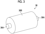
- Fig. 3 is a perspective view of the drying cylinder 36.
- the drying cylinder 36 is formed of a cylindrical steel use stainless (SUS), and comprises a rotation shaft 36A and an outer peripheral surface 36B.
- SUS cylindrical steel use stainless
- the substrate S is wound around the outer peripheral surface 36B of the drying cylinder 36.
- the outer peripheral surface 36B of the drying cylinder 36 is heated by a heater 36C provided inside the drying cylinder 36.
- the drying cylinder 36 heats the substrate S by bringing the substrate S into contact with the outer peripheral surface 36B.
- the drying cylinder 36 is rotationally driven about the rotation shaft 36Aby a motor 36D.
- the drying cylinder 36 rotates about the rotation shaft 36A while holding an opposite surface, which is a surface of the substrate S opposite to the recording surface, on the outer peripheral surface 36B, and thus the substrate S is transported while being heated from the opposite surface.
- the opposite surface of the substrate S is the back surface of the substrate S in a case of the front surface printing and main drying unit 16, and is the front surface of the substrate S in a case of the back surface printing and main drying unit 20.
- the substrate S heated by the drying cylinder 36 is guided by the pass rollers 30 and discharged from the drying cylinder 36 to the outside of the printing and main drying unit 60.
- Fig. 4 is a block diagram showing an electric configuration of the ink jet recording device 10.
- the ink jet recording device 10 comprises an overall control unit 50, a transport control unit 52, a pre-drying control unit 54, a printing control unit 56, and a drying control unit 58.
- the overall control unit 50 performs overall control of the ink jet recording device 10.
- the overall control unit 50 comprises a processor 50A and a memory 50B.
- the processor 50A executes a command stored in the memory 50B.
- a hardware structure of the processor 50A is various processors as described below.
- the various processors include a central processing unit (CPU) that is a general-purpose processor acting as various functional units by executing software (program), a graphics processing unit (GPU) that is a processor specialized in image processing, a programmable logic device (PLD) such as a field programmable gate array (FPGA) that is a processor having a circuit configuration changeable after manufacture, a dedicated electric circuit such as an application specific integrated circuit (ASIC) that is a processor having a circuit configuration dedicatedly designed to execute specific processing, and the like.
- CPU central processing unit
- GPU graphics processing unit
- PLD programmable logic device
- FPGA field programmable gate array
- ASIC application specific integrated circuit
- One processing unit may be configured by using one of these various processors, or may be configured by using two or more processors of the same type or different types (for example, a plurality of FPGAs, or a combination of a CPU and an FPGA, or a combination of a CPU and a GPU).
- a plurality of functional units may be configured by one processor.
- one processor constitutes the plurality of functional units
- first there is a form in which a combination of one or more CPUs and software constitutes one processor, as represented by a computer, such as a client and a server, and the processor acts as the plurality of functional units.
- a processor that realizes functions of the entire system including the plurality of functional units with one integrated circuit (IC) chip is used, as represented by a system on chip (SoC) or the like.
- SoC system on chip
- various functional units are configured by using one or more of the above-described various processors as hardware structures.
- the hardware structure of the various processors is more specifically an electric circuit (circuitry) in which circuit elements such as semiconductor elements are combined.
- the memory 50B stores a command to be executed by the processor 50A.
- the memory 50B includes a random access memory (RAM) and a read only memory (ROM).
- the processor 50A executes software using various programs and parameters stored in the ROM with the RAM as a work area and executes various types of processing for controlling the ink jet recording device 10 using the parameters stored in the ROM or the like.
- the transport control unit 52 controls the motor of the paper feed unit 12, the turn bar of the reversing unit 18, and the motor (an example of a "transport device") of the paper discharge unit 22 to apply a predetermined transport tension (an example of a "tension") to the substrate S and transport the substrate S at a predetermined transport speed.
- the transport control unit 52 controls driving of the drying cylinders 36 of the front surface printing and main drying unit 16 and the back surface printing and main drying unit 20.
- the pre-drying control unit 54 controls the heating device of the pre-drying unit 14 to preliminarily dry the substrate S.
- the printing control unit 56 controls the ink jet heads 32 of the front surface printing and main drying unit 16 and the back surface printing and main drying unit 20 to form an image on the substrate S.
- the drying control unit 58 controls the radiation heating units 34 and the drying cylinders 36 of the front surface printing and main drying unit 16 and the back surface printing and main drying unit 20 to dry the ink applied to the substrate S.
- the substrate S supplied from the paper feed unit 12 is transported to the pre-drying unit 14 and is preliminarily dried.
- the preliminarily dried substrate S is transported to the front surface printing and main drying unit 16.
- the substrate S is guided by the pass rollers 30 and transported to a position facing the inkjet head 32.
- the ink jet head 32 jets liquid droplets of the aqueous ink toward the front surface of the substrate S.
- the image is formed on the front surface of the substrate S by the liquid droplets adhering to the front surface of the substrate S.
- the substrate S is transported to a position facing the radiation heating unit 34.
- the radiation heating unit 34 heats the substrate S with the infrared heater. In this manner, the drying of the aqueous ink applied to the front surface of the substrate S is promoted.
- the substrate S is guided by the pass rollers 30 and transported to the drying cylinder 36 from a position facing the radiation heating unit 34.
- the substrate S is wound around the outer peripheral surface 36B of the drying cylinder 36.
- the drying cylinder 36 rotates while bringing the outer peripheral surface 36B into contact with the back surface of the substrate S, thereby transporting the substrate S while heating the substrate S from the back surface. In this manner, the drying of the aqueous ink applied to the front surface of the substrate S is promoted.
- the substrate S on which the aqueous ink applied to the front surface is dried is discharged to the outside of the front surface printing and main drying unit 16.
- the substrate S discharged from the front surface printing and main drying unit 16 is transported to the reversing unit 18, and the front and back sides thereof are reversed by the turn bar.
- the substrate S of which the front and back sides are reversed is transported to the back surface printing and main drying unit 20.
- the substrate S is guided by the pass rollers 30 and transported to a position facing the ink jet head 32.
- the ink jet head 32 jets liquid droplets of the aqueous ink toward the back surface of the substrate S.
- the image is formed on the back surface of the substrate S by the liquid droplets adhering to the back surface of the substrate S.
- the substrate S is transported to a position facing the radiation heating unit 34.
- the radiation heating unit 34 heats the substrate S with the infrared heater. In this manner, the drying of the aqueous ink applied to the back surface of the substrate S is promoted.
- the substrate S is guided by the pass rollers 30 and transported to the drying cylinder 36 from a position facing the radiation heating unit 34.
- the substrate S is wound around the outer peripheral surface 36B of the drying cylinder 36.
- the drying cylinder 36 rotates while bringing the outer peripheral surface 36B into contact with the front surface of the substrate S, thereby transporting the substrate S while heating the substrate S from the front surface. In this manner, the drying of the aqueous ink applied to the back surface of the substrate S is promoted.
- the substrate S on which the aqueous ink applied to the back surface is dried is discharged to the outside of the back surface printing and main drying unit 20.
- the substrate S discharged from the back surface printing and main drying unit 20 is transported to the paper discharge unit 22 and is wound around the winding roll.
- the ink jet recording device 10 transports the substrate S in the order of the paper feed unit 12, the pre-drying unit 14, the front surface printing and main drying unit 16, the reversing unit 18, the back surface printing and main drying unit 20, and the paper discharge unit 22, and performs each treatment on the substrate S to manufacture a printed matter.
- a degree of an image defect generated in a case where the front surface of the substrate S on which a blue solid image was formed was rubbed with the outer peripheral surface 36B of the drying cylinder 36 at a surface pressure of 0.42 [kg/cm 2 ] was evaluated.
- the degree of the image defect was rated as follows. The grade 3 or higher is pass.
- the maximum static friction coefficient was changed using two polishing methods of buff polishing and abrasive polishing.
- the maximum static friction coefficient was measured by a gradient method partially conforming to JIS P 8147: 2010, using a drying cylinder sample with respect to the substrate.
- OK Top Coat manufactured by Oji Paper Co., Ltd., "Top Coat” is a registered trademark
- the drying cylinder sample has a cylindrical shape with ⁇ 100 [mm] and a length of 1000 [mm].
- Fig. 5 is a graph showing a result of the evaluation of the degree of the image defect, in which the maximum static friction coefficient is plotted on a horizontal axis and an image defect grade is plotted on a vertical axis.
- a dotted line shown in Fig. 5 is an approximate curve for each plotted point. As shown in Fig. 5 , it was found that the smaller the maximum static friction coefficient, the better the image defect grade, and the maximum static friction coefficient of 0.54 or less is a pass level.
- the maximum static friction coefficient may be measured using a portable friction meter 3D MUSE TYPE37i (manufactured by Shinto Scientific Co., Ltd.). With this device, a drying cylinder sample is not required.
- a floating amount h 0 [ ⁇ m] of the substrate from the drying cylinder can be represented by the following Expression 1.
- R is a radius [m] of a drying cylinder
- ⁇ is a gas viscosity [Pa ⁇ s]
- T is a tension [N] of a substrate
- w is a width (length in a width direction) [m] of the substrate
- Ur is a speed [m/min] of the drying cylinder
- Uw is a transport speed [m/min] of the substrate.
- ⁇ is a composite surface roughness [ ⁇ m] of the outer peripheral surface of the drying cylinder, and can be represented by the following Expression 2.
- ⁇ Rq 2 + Rw 2 1 / 2
- a key parameter of the floating amount is the arithmetic average roughness of the outer peripheral surface of the drying cylinder, and the larger the arithmetic average roughness, the better.
- a method of processing a drying cylinder for changing a maximum static friction coefficient and an arithmetic average roughness of the outer peripheral surface includes first performing a roughening treatment (blasting treatment) on an outer peripheral surface of a cylinder having a cylindrical shape, next performing a plating treatment on the outer peripheral surface, and finally performing a smoothing treatment (polishing) on the outer peripheral surface.
- blasting treatment examples include sand blasting, shot blasting, grit blasting, and wet blasting.
- Examples of a polishing method include abrasive polishing, buff polishing, barrel polishing, belt polishing, and lapping polishing.
- abrasive polishing alumina, silicon carbide, diamond, and cubic boron nitride (CBN) are used.
- CBN cubic boron nitride
- buff polishing linen, cotton, wool, and sponge are used.
- the maximum static friction coefficient and the arithmetic average roughness of the outer peripheral surface of the drying cylinder can be changed by changing the blasting treatment and the polishing method. For example, as shown in Fig. 5 , the maximum static friction coefficient tends to be smaller in the buff polishing than in the abrasive polishing.
- Figs. 6A to 6D is an enlarged image of the outer peripheral surface of the drying cylinder.
- Fig. 6A is an enlarged image of the outer peripheral surface subjected to the abrasive polishing
- Fig. 6B is an image obtained by further enlarging Fig. 6A
- Fig. 6C is an enlarged image of the outer peripheral surface subjected to the buff polishing
- Fig. 6D is an image obtained by further enlarging Fig. 6C .
- the outer peripheral surface processed by the buff polishing is flatter than the outer peripheral surface processed by the abrasive polishing. Therefore, it is considered that the surface pressure and the maximum static friction coefficient are lower in the buff polishing than in the abrasive polishing. That is, as the method of processing the drying cylinder, it is preferable to perform a smoothing treatment by the buff polishing.
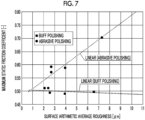
- Fig. 7 is a graph showing a relationship between the arithmetic average roughness [ ⁇ m] of the outer peripheral surface of the drying cylinder and the maximum static friction coefficient.
- Fig. 7 shows a drying cylinder of which an outer peripheral surface is subjected to the abrasive polishing and a drying cylinder of which an outer peripheral surface is subjected to the buff polishing. Dotted lines shown in Fig. 7 are approximate straight lines for plotted points of the abrasive polishing and plotted points of the buff polishing.
- the maximum static friction coefficient increases as the arithmetic average roughness increases, but in the buff polishing, the maximum static friction coefficient hardly changes even though the arithmetic average roughness increases.
- Fig. 8 is a table showing the arithmetic average roughness of the outer peripheral surface of the drying cylinder before and after the smoothing treatment.
- a maximum height roughness Rz [ ⁇ m] was increased before and after polishing.
- the maximum height roughness Rz was reduced by 0.35 [ ⁇ m] or more before and after polishing. That is, as the method of processing the drying cylinder, it is preferable to reduce the maximum height roughness of the outer peripheral surface of the drying cylinder by 0.35 or more in the smoothing treatment of the buff polishing.
- the substrate S is dried by the radiation heating unit 34 and the drying cylinder 36.
- the drying is too weak, an image surface is very sticky, and thus the measures for the drying cylinder 36 described above may not be sufficient.
- the occurrence of white spots and blisters was evaluated for the drying cylinder of which the outer peripheral surface was subjected to the buff polishing and the drying cylinder of which the outer peripheral surface was subjected to the abrasive polishing.
- the solvent amount of the ink on the recording surface of the substrate was changed to 50 to 300 [ ⁇ g/cm 2 ].
- the solvent of the ink is uniformly distributed in each substrate.
- the evaluation of the occurrence of the white spots and the blisters was determined as follows. The grades A, B, and C are pass, and the grade D is fail.
- Fig. 9 is a table showing evaluation results of white spots and blisters.
- the occurrence of white spots and blisters was determined to be the grade C or higher in a case where the solvent amount was in a range of 50 to 300 [ ⁇ g/cm 2 ].
- the occurrence of white spots was determined to be the grade D in a case where the solvent amount was 300 [ ⁇ g/cm 2 ] and 250 [ ⁇ g/cm 2 ].
- the solvent amount of the ink on the recording surface of the substrate that comes into contact with the outer peripheral surface of the drying cylinder is preferably 200 [ ⁇ g/cm 2 ] or less, and more preferably 148 [ ⁇ g/cm 2 ] or less.
- the solvent amount of the ink on the front surface of the substrate S that comes into contact with the outer peripheral surface 36B of the drying cylinder 36 of the back surface printing and main drying unit 20 can be set to a desired solvent amount by drying the substrate S by the radiation heating unit 34 and the drying cylinder 36 of the front surface printing and main drying unit 16.
- the solvent amount of the ink is small, but since excessive drying can affect the quality of the printed matter itself, such as causing blisters, it is practically preferable that the solvent amount is 50 [ ⁇ g/cm 2 ] or more.
- temperatures of the radiation heating unit 34 and the drying cylinder 36 are adjusted such that the temperature of the substrate S is in a range of 90 [°C] or more and 180 [°C] or less. That is, the drying cylinder 36 sets the temperature of the substrate S to 90 [°C] or higher and 180 [°C] or lower while the substrate S is in contact with the drying cylinder 36.
- the maximum static friction coefficient of the outer peripheral surface 36B of the drying cylinder 36 is set to 0.1 or more.
- the arithmetic average roughness of the outer peripheral surface 36B of the drying cylinder 36 is set to 10.4 [ ⁇ m] or less obtained from an intersection point between an approximate straight line for the plotted points of the abrasive polishing shown in Fig. 7 and 0.8, which is a realistic value of the maximum static friction coefficient.
- the measures for the outer peripheral surface 36B of the drying cylinder 36 described above become more effective by satisfying the following.
- the transport tension of the substrate S is set in a range of 50 [N/m] or more and 800 [N/m] or less according to the transport speed of the substrate S and the application.
- the temperature of the outer peripheral surface of the drying cylinder 36 is set in a range of 30 [°C] or more and 300 [°C] or less according to the transport speed and the type of the substrate S. Since the drying cylinder 36 is driving, and no speed difference occurs between the drying cylinder 36 and the substrate S, image defects are less likely to occur than in a case where the drying cylinder 36 is driven.
- the substrate S is paper.
- the paper is not limited to inkjet dedicated paper, and includes paper mainly composed of cellulose, such as coated paper.
- the substrate S may be art paper, coated paper, lightweight coated paper, cast paper, or fine coated paper.
- the substrate S may have a moisture content of 1.2% or more and 14.3% or less before the ink is applied to the recording surface.
- the moisture content of the substrate S can be adjusted by the pre-drying unit 14.
- the moisture content of the substrate S can be adjusted by the radiation heating unit 34 and the drying cylinder 36 of the front surface printing and main drying unit 16.
- a melting point of the wax contained in the ink is important for reducing stickiness.
- the melting point of the wax may be 90°C or lower.
- the melting point of the wax is preferably as low as possible as long as the wax does not bleed at room temperature (the wax does not separate and precipitate on the surface of the image), but a low melting point of a paraffin wax of 47°C or higher is appropriate.
- the drying cylinder 36 can achieve its original purpose of contact heating the substrate, without damaging the image surface, and can suppress slippage during transport.
- Fig. 10 is a configuration diagram showing an outline of a printing and main drying unit 60A according to a first modification example. Parts common to Fig. 2 will be designated by the same reference numerals and will not be described in detail.
- the printing and main drying unit 60A comprises ink jet heads 32C, 32M, 32Y, and 32K and a printing cylinder 38.
- the plurality of pass rollers 30 are disposed on a transport path of the substrate S in the printing and main drying unit 60.
- the substrate S carried into the printing and main drying unit 60 is transported to the printing cylinder 38 by the pass rollers 30.
- the substrate S is wound around an outer peripheral surface of the printing cylinder 38.
- the printing cylinder 38 is rotationally driven by a motor (not shown) about a rotation shaft (not shown).
- the printing cylinder 38 holds an opposite surface of the substrate S opposite to the recording surface on the outer peripheral surface and rotates about the rotation shaft to transport the substrate S.
- the outer peripheral surface may be provided with an adsorption hole for adsorbing the substrate S to the outer peripheral surface.
- the ink jet heads 32C, 32M, 32Y, and 32K are liquid jetting heads that jet aqueous inks of cyan (C), magenta (M), yellow (Y), and black (K) by an ink jet method, respectively.
- Each of the ink jet heads 32C, 32M, 32Y, and 32K is disposed at regular intervals along the transport path of the substrate S using the printing cylinder 38.
- the substrate S which is transported by the printing cylinder 38 and has the recording surface on which the image is formed by the inkjet heads 32C, 32M, 32Y, and 32K is transported to the drying cylinder 36.
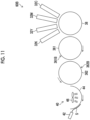
- Fig. 11 is a configuration diagram showing an outline of a printing and main drying unit 60B according to a second modification example. Parts common to Fig. 10 will be designated by the same reference numerals and will not be described in detail.
- the printing and main drying unit 60B is a unit for forming an image on the recording surface of the substrate S in a sheet form, and comprises a first drying cylinder 361, a second drying cylinder 362, and a cooling unit 40.
- the substrate S which is transported by the printing cylinder 38 and has the recording surface on which the image is formed by the ink jet heads 32C, 32M, 32Y, and 32K is delivered from the printing cylinder 38 to the first drying cylinder 361.
- the first drying cylinder 361 rotates about a rotation shaft with a first outer peripheral surface 361B in contact with the recording surface of the substrate S, thereby transporting the substrate S while heating the substrate S from the recording surface.
- the substrate S on which drying of the aqueous ink is promoted is delivered from the first drying cylinder 361 to the second drying cylinder 362.
- the second drying cylinder 362 rotates about a rotation shaft by bringing a second outer peripheral surface 362B into contact with the opposite surface of the substrate S opposite to the recording surface, thereby transporting the substrate S while heating the substrate S from the opposite surface.
- the substrate S on which drying of the aqueous ink is promoted is delivered from the second drying cylinder 362 to the cooling unit 40.
- the cooling unit 40 comprises a holding portion 42, a sliding cooling member 44, and a cold air fan 46.
- the holding portion 42 holds a tip part of the substrate S delivered from the second drying cylinder 362 and transports the substrate S in a transport path along the sliding cooling member 44.
- the substrate S transported by the holding portion 42 has a recording surface that slides on the sliding cooling member 44.
- the sliding cooling member 44 is cooled by the cold air fan 46 from a side opposite to a surface on which the substrate S slides. Therefore, the substrate S is cooled by the sliding cooling member 44 and is discharged to the outside of the printing and main drying unit 60B.
- the substrate S an example of paper has been described as the substrate S, but various recording media can be used as the substrate S regardless of the material and shape, such as a resin sheet and a film.
Landscapes
- Health & Medical Sciences (AREA)
- General Health & Medical Sciences (AREA)
- Toxicology (AREA)
- Engineering & Computer Science (AREA)
- Mechanical Engineering (AREA)
- Ink Jet (AREA)
Abstract
Description
- The present invention relates to an ink jet recording device and a method of manufacturing a drying cylinder, and particularly relates to a technique of drying a recording medium on which an image is formed.
- It is known that a rub resistance and blocking can be suppressed by drying a recording medium on which ink is applied to form an image, such that an amount of a residual solvent is a certain amount or less. However, in a double-sided roll printer that forms images on both surfaces of a roll substrate, only by a certain amount or more of drying, it is difficult to prevent damage to the image on an uneven surface required to suppress slippage of the recording medium during transportation.
- In the first place, some inkjet printing devices have a drying cylinder that dries an image by heat transfer after the image is formed on a recording medium. For example,
JP2020-082650A - In order to efficiently dry a recording medium on a drying cylinder, it is preferable that a contact area between the drying cylinder and the recording medium is as large as possible. However, in a case where the drying cylinder has a flat structure, slippage may occur due to air (entrained air) generated between the drying cylinder and the recording medium, and transport performance may deteriorate. As a solution, a surface of the drying cylinder is often processed to have an uneven shape such as a suction or grooved roll for allowing the entrained air to escape. On the other hand, in a double-sided printer or the like, in drying after image formation on a back surface, an image formation region on a front surface where the image is previously formed comes into contact with a protruding portion on the surface of the drying cylinder, and thus an ink film is peeled off at a contact portion, and image defects such as white spots may occur.
- The present invention has been made in view of such circumstances, and an object of the present invention is to provide an ink jet recording device and a method of manufacturing a drying cylinder, which suppress drying unevenness while suppressing slippage of a recording medium.
- In order to achieve the above object, according to a first aspect of the present disclosure, there is provided an ink jet recording device comprising: an ink jet head that applies an ink to a recording surface of a recording medium to form an image; and a drying cylinder that heats the recording medium by bringing the recording surface of the recording medium to which the ink is applied into contact with an outer peripheral surface of the drying cylinder, in which the outer peripheral surface of the drying cylinder has a maximum static friction coefficient of 0.54 or less and an arithmetic average roughness of 1.6 µm or more, and a solvent amount of the ink on the recording surface that comes into contact with the outer peripheral surface of the drying cylinder is 200 µg/cm2 or less. According to this aspect, it is possible to suppress the drying unevenness while suppressing the slippage of the recording medium.
- An ink jet recording device according to a second aspect of the present disclosure is the ink jet recording device according to the first aspect, further comprising a transport device that transports the recording medium, in which the transport device applies a tension of 50 N/m or more and 800 N/m or less to the recording medium.
- An ink jet recording device according to a third aspect of the present disclosure is the ink jet recording device according to the first or second aspect, in which the drying cylinder includes a heater, and the heater sets a temperature of the outer peripheral surface of the drying cylinder to 30°C or higher and 300°C or lower.
- An ink jet recording device according to a fourth aspect of the present disclosure is the ink jet recording device according to any one of the first to third aspects, in which the drying cylinder includes a motor that rotates the drying cylinder about a shaft of the drying cylinder, and the drying cylinder transports the recording medium while holding the recording medium on the outer peripheral surface.
- An ink jet recording device according to a fifth aspect of the present disclosure is the ink jet recording device according to any one of the first to fourth aspects, in which a moisture content of the recording medium before the ink is applied to the recording surface is 1.2% or more and 14.3% or less.
- An ink jet recording device according to a sixth aspect of the present disclosure is the ink jet recording device according to any one of the first to fifth aspects, in which the drying cylinder sets a temperature of the recording medium to 90°C or higher and 180°C or lower.
- An inkjet recording device according to a seventh aspect of the present disclosure is the ink jet recording device according to any one of the first to sixth aspects, in which the ink contains a wax, and a melting point of the wax is 90°C or lower. Furthermore, the melting point of the wax is preferably 47°C or higher.
- An ink jet recording device according to an eighth aspect of the present disclosure is the ink jet recording device according to any one of the first to seventh aspects, in which the outer peripheral surface of the drying cylinder has the maximum static friction coefficient of 0.1 or more and the arithmetic average roughness of 10.4 µm or less, and the solvent amount of the ink on the recording surface that comes into contact with the outer peripheral surface of the drying cylinder is 100 µg/cm2 or more. The solvent amount of the ink on the recording surface that comes into contact with the outer peripheral surface of the drying cylinder is more preferably 148 µg/cm2 or less.
- In order to achieve the above object, according to a ninth aspect of the present disclosure, there is provided an ink jet recording device comprising: a first ink jet head that applies an ink to a first recording surface of a recording medium to form an image; a first drying cylinder that heats the recording medium by bringing a second recording surface, which is an opposite surface of the first recording surface of the recording medium to which the ink is applied, into contact with a first outer peripheral surface; a reversing mechanism that reverses front and back sides of the recording medium; a second ink jet head that applies the ink to the second recording surface of the recording medium to form an image; a second drying cylinder that heats the recording medium by bringing the first recording surface of the recording medium into contact with a second outer peripheral surface, in which a solvent amount of the ink on the first recording surface in the first drying cylinder is 200 µg/cm2 or less, and the second outer peripheral surface of the second drying cylinder has a maximum static friction coefficient of 0.54 or less and an arithmetic average roughness of 1.6 µm or more. According to this aspect, it is possible to suppress the drying unevenness while suppressing the slippage of the recording medium.
- In order to achieve the above object, according to a tenth aspect of the present disclosure, there is provided a method of manufacturing a drying cylinder, comprising: performing a roughening treatment on an outer peripheral surface of a cylinder having a cylindrical shape; and performing a smoothing treatment on the outer peripheral surface on which the roughening treatment is performed, to make the outer peripheral surface have a maximum static friction coefficient of 0.54 or less and an arithmetic average roughness of 1.6 µm or more. According to this aspect, it is possible to manufacture a drying cylinder that suppresses the drying unevenness while suppressing the slippage of the recording medium.
- A method of manufacturing a drying cylinder according to an eleventh aspect is the method of manufacturing a drying cylinder according to the tenth aspect, in which, in the smoothing treatment, a maximum height roughness of the outer peripheral surface of the cylinder is reduced by 0.35 µm or more.
- A method of manufacturing a drying cylinder according to a twelfth aspect is the method of manufacturing a drying cylinder according to the tenth or eleventh aspect, in which the smoothing treatment is performed by buff polishing.
- According to the present invention, it is possible to suppress the drying unevenness while suppressing the slippage of the recording medium.
-
-
Fig. 1 is an overall configuration diagram of an ink jet recording device. -
Fig. 2 is a configuration diagram showing an outline of a printing and main drying unit. -
Fig. 3 is a perspective view of a drying cylinder. -
Fig. 4 is a block diagram showing an electric configuration of the ink jet recording device. -
Fig. 5 is a graph showing a result of evaluation of a degree of an image defect. -
Figs. 6A to 6D is an enlarged image of an outer peripheral surface of the drying cylinder. -
Fig. 7 is a graph showing a relationship between an arithmetic average roughness and a maximum static friction coefficient of the outer peripheral surface of the drying cylinder. -
Fig. 8 is a table showing an arithmetic average roughness of the outer peripheral surface of the drying cylinder before and after smoothing processing. -
Fig. 9 is a table showing evaluation results of white spots and blisters. -
Fig. 10 is a configuration diagram showing an outline of a printing and main drying unit according to a first modification example. -
Fig. 11 is a configuration diagram showing an outline of a printing and main drying unit according to a second modification example. - Hereinafter, a preferred embodiment of the present invention will be described with reference to the accompanying drawings. In the following, a traveling direction of a substrate S is referred to as a transport direction, and a direction perpendicular to the transport direction and parallel to a recording surface of the substrate S is referred to as a width direction.
-
Fig. 1 is an overall configuration diagram of an inkjet recording device 10. The inkjet recording device 10 is a printing system that transports a substrate S, which is a long roll-shaped recording medium, in a so-called roll-to-roll method and forms an image by aqueous ink jet printing of a single-pass method without applying a pretreatment liquid. As shown inFig. 1 , the inkjet recording device 10 comprises apaper feed unit 12, apre-drying unit 14, a front surface printing andmain drying unit 16, areversing unit 18, a back surface printing andmain drying unit 20, and apaper discharge unit 22. - The
paper feed unit 12 comprises a delivery roller (not shown) around which the substrate S on which the image is not yet formed is wound in a roll shape. Thepaper feed unit 12 supplies the substrate S on which the image is not yet formed by rotationally driving the delivery roller by a motor (not shown). The substrate S supplied from the delivery roller is transported to thepre-drying unit 14. - The
pre-drying unit 14 heats and preliminarily dries the substrate S while transporting the substrate S, by a heating device (not shown). The substrate S discharged from thepre-drying unit 14 is transported to the front surface printing andmain drying unit 16. - The front surface printing and
main drying unit 16 applies aqueous ink to a front surface of the substrate S (an example of a "recording surface" and an example of a "first recording surface") using an ink jet head 32 (seeFig. 2 , an example of a "first ink jet head") while transporting the substrate S, and forms an image. In addition, the front surface printing andmain drying unit 16 dries the aqueous ink applied to the substrate S by a radiation heating unit 34 (seeFig. 2 ) and a drying cylinder 36 (seeFig. 2 ) while transporting the substrate S. The substrate S discharged from the front surface printing andmain drying unit 16 is transported to thereversing unit 18. - The
reversing unit 18 includes a turn bar (not shown). The turn bar (an example of a "reversing mechanism") reverses front and back sides of the substrate S. The substrate S of which the front and back sides are reversed is transported to the back surface printing andmain drying unit 20. - The back surface printing and
main drying unit 20 is configured similarly to the front surface printing andmain drying unit 16. The back surface printing andmain drying unit 20 applies aqueous ink to a back surface of the substrate S (an example of a "recording surface" and an example of a "second recording surface") using the ink jet head 32 (an example of a "second ink jet head") while transporting the substrate S, and forms an image. In addition, the back surface printing andmain drying unit 20 dries the aqueous ink applied to the substrate S by theradiation heating unit 34 and the dryingcylinder 36 while transporting the substrate S. The substrate S discharged from the back surface printing andmain drying unit 20 is transported to thepaper discharge unit 22. - The
paper discharge unit 22 comprises a winding roll (not shown) connected to a motor (not shown). The winding roll is rotationally driven by the motor so that thepaper discharge unit 22 winds the substrate S on which the image is formed around the winding roll. - The front surface printing and
main drying unit 16 and the back surface printing andmain drying unit 20 have the same configuration. Here, a printing andmain drying unit 60 will be described. -
Fig. 2 is a configuration diagram showing an outline of the printing andmain drying unit 60. The printing andmain drying unit 60 comprises a plurality ofpass rollers 30, theink jet head 32, theradiation heating unit 34, and the dryingcylinder 36. - The plurality of
pass rollers 30 are disposed on a transport path of the substrate S in the printing andmain drying unit 60. The substrate S carried into the printing andmain drying unit 60 is transported inside the printing andmain drying unit 60 by thepass rollers 30 and is discharged to the outside of the printing andmain drying unit 60. - The
ink jet head 32 is disposed at a position facing the recording surface of the substrate S to be transported. The recording surface of the substrate S is the front surface of the substrate S in a case of the front surface printing andmain drying unit 16, and is the back surface of the substrate S in a case of the back surface printing andmain drying unit 20. Theink jet head 32 is a liquid jetting head that forms an image by applying the aqueous ink to the recording surface of the substrate S by an ink jet method. Theink jet head 32 is configured as a line type recording head that can form an image on the transported substrate S by one-time scanning. Theink jet head 32 comprises a nozzle surface (not shown) on which a plurality of nozzles, which are jetting ports of the aqueous ink, are two-dimensionally arranged, and the nozzle surface is disposed to face the recording of the substrate S. - The
ink jet head 32 can be configured by connecting a plurality of head modules in the width direction of the substrate S. The aqueous ink is supplied to theink jet head 32 from an ink tank (not shown) via a pipe path (not shown). - The aqueous ink refers to an ink obtained by dissolving or dispersing a coloring material such as a dye or a pigment in water and a water-soluble solvent. Here, an aqueous pigment ink is used as the aqueous ink. In addition, the aqueous ink contains a wax.
- The substrate S is guided by the
pass rollers 30 and transported from a position facing theink jet head 32 to a position facing theradiation heating unit 34. - The
radiation heating unit 34 includes an infrared heater (not shown). The infrared heater heats the substrate S by radiating infrared rays toward the surface of the substrate S. Theradiation heating unit 34 may comprise a hot air fan that supplies hot air to the surface of the substrate S. - The substrate S is guided by the
pass rollers 30 and transported to the dryingcylinder 36 from a position facing theradiation heating unit 34. -
Fig. 3 is a perspective view of the dryingcylinder 36. As shown inFig. 3 , the dryingcylinder 36 is formed of a cylindrical steel use stainless (SUS), and comprises arotation shaft 36A and an outerperipheral surface 36B. - Returning to the description of
Fig. 2 , the substrate S is wound around the outerperipheral surface 36B of the dryingcylinder 36. The outerperipheral surface 36B of the dryingcylinder 36 is heated by aheater 36C provided inside the dryingcylinder 36. The dryingcylinder 36 heats the substrate S by bringing the substrate S into contact with the outerperipheral surface 36B. In addition, the dryingcylinder 36 is rotationally driven about the rotation shaft 36Aby amotor 36D. The dryingcylinder 36 rotates about therotation shaft 36A while holding an opposite surface, which is a surface of the substrate S opposite to the recording surface, on the outerperipheral surface 36B, and thus the substrate S is transported while being heated from the opposite surface. The opposite surface of the substrate S is the back surface of the substrate S in a case of the front surface printing andmain drying unit 16, and is the front surface of the substrate S in a case of the back surface printing andmain drying unit 20. - The substrate S heated by the drying
cylinder 36 is guided by thepass rollers 30 and discharged from the dryingcylinder 36 to the outside of the printing andmain drying unit 60. -
Fig. 4 is a block diagram showing an electric configuration of the inkjet recording device 10. The inkjet recording device 10 comprises anoverall control unit 50, atransport control unit 52, apre-drying control unit 54, aprinting control unit 56, and a dryingcontrol unit 58. - The
overall control unit 50 performs overall control of the inkjet recording device 10. Theoverall control unit 50 comprises aprocessor 50A and amemory 50B. - The
processor 50A executes a command stored in thememory 50B. A hardware structure of theprocessor 50A is various processors as described below. The various processors include a central processing unit (CPU) that is a general-purpose processor acting as various functional units by executing software (program), a graphics processing unit (GPU) that is a processor specialized in image processing, a programmable logic device (PLD) such as a field programmable gate array (FPGA) that is a processor having a circuit configuration changeable after manufacture, a dedicated electric circuit such as an application specific integrated circuit (ASIC) that is a processor having a circuit configuration dedicatedly designed to execute specific processing, and the like. - One processing unit may be configured by using one of these various processors, or may be configured by using two or more processors of the same type or different types (for example, a plurality of FPGAs, or a combination of a CPU and an FPGA, or a combination of a CPU and a GPU). In addition, a plurality of functional units may be configured by one processor. As an example in which one processor constitutes the plurality of functional units, first, there is a form in which a combination of one or more CPUs and software constitutes one processor, as represented by a computer, such as a client and a server, and the processor acts as the plurality of functional units. Second, there is a form in which a processor that realizes functions of the entire system including the plurality of functional units with one integrated circuit (IC) chip is used, as represented by a system on chip (SoC) or the like. As described above, various functional units are configured by using one or more of the above-described various processors as hardware structures.
- Furthermore, the hardware structure of the various processors is more specifically an electric circuit (circuitry) in which circuit elements such as semiconductor elements are combined.
- The
memory 50B stores a command to be executed by theprocessor 50A. Thememory 50B includes a random access memory (RAM) and a read only memory (ROM). Theprocessor 50A executes software using various programs and parameters stored in the ROM with the RAM as a work area and executes various types of processing for controlling the inkjet recording device 10 using the parameters stored in the ROM or the like. - The
transport control unit 52 controls the motor of thepaper feed unit 12, the turn bar of the reversingunit 18, and the motor (an example of a "transport device") of thepaper discharge unit 22 to apply a predetermined transport tension (an example of a "tension") to the substrate S and transport the substrate S at a predetermined transport speed. In addition, thetransport control unit 52 controls driving of the dryingcylinders 36 of the front surface printing andmain drying unit 16 and the back surface printing andmain drying unit 20. - The
pre-drying control unit 54 controls the heating device of thepre-drying unit 14 to preliminarily dry the substrate S. - The
printing control unit 56 controls the ink jet heads 32 of the front surface printing andmain drying unit 16 and the back surface printing andmain drying unit 20 to form an image on the substrate S. In addition, the dryingcontrol unit 58 controls theradiation heating units 34 and the dryingcylinders 36 of the front surface printing andmain drying unit 16 and the back surface printing andmain drying unit 20 to dry the ink applied to the substrate S. - The substrate S supplied from the
paper feed unit 12 is transported to thepre-drying unit 14 and is preliminarily dried. The preliminarily dried substrate S is transported to the front surface printing andmain drying unit 16. - In the front surface printing and
main drying unit 16, the substrate S is guided by thepass rollers 30 and transported to a position facing theinkjet head 32. Theink jet head 32 jets liquid droplets of the aqueous ink toward the front surface of the substrate S. The image is formed on the front surface of the substrate S by the liquid droplets adhering to the front surface of the substrate S. - Subsequently, the substrate S is transported to a position facing the
radiation heating unit 34. Theradiation heating unit 34 heats the substrate S with the infrared heater. In this manner, the drying of the aqueous ink applied to the front surface of the substrate S is promoted. - Further, the substrate S is guided by the
pass rollers 30 and transported to the dryingcylinder 36 from a position facing theradiation heating unit 34. The substrate S is wound around the outerperipheral surface 36B of the dryingcylinder 36. The dryingcylinder 36 rotates while bringing the outerperipheral surface 36B into contact with the back surface of the substrate S, thereby transporting the substrate S while heating the substrate S from the back surface. In this manner, the drying of the aqueous ink applied to the front surface of the substrate S is promoted. - The substrate S on which the aqueous ink applied to the front surface is dried is discharged to the outside of the front surface printing and
main drying unit 16. - The substrate S discharged from the front surface printing and
main drying unit 16 is transported to the reversingunit 18, and the front and back sides thereof are reversed by the turn bar. The substrate S of which the front and back sides are reversed is transported to the back surface printing andmain drying unit 20. - In the back surface printing and
main drying unit 20, the substrate S is guided by thepass rollers 30 and transported to a position facing theink jet head 32. Theink jet head 32 jets liquid droplets of the aqueous ink toward the back surface of the substrate S. The image is formed on the back surface of the substrate S by the liquid droplets adhering to the back surface of the substrate S. - Subsequently, the substrate S is transported to a position facing the
radiation heating unit 34. Theradiation heating unit 34 heats the substrate S with the infrared heater. In this manner, the drying of the aqueous ink applied to the back surface of the substrate S is promoted. - Further, the substrate S is guided by the
pass rollers 30 and transported to the dryingcylinder 36 from a position facing theradiation heating unit 34. The substrate S is wound around the outerperipheral surface 36B of the dryingcylinder 36. The dryingcylinder 36 rotates while bringing the outerperipheral surface 36B into contact with the front surface of the substrate S, thereby transporting the substrate S while heating the substrate S from the front surface. In this manner, the drying of the aqueous ink applied to the back surface of the substrate S is promoted. - The substrate S on which the aqueous ink applied to the back surface is dried is discharged to the outside of the back surface printing and
main drying unit 20. The substrate S discharged from the back surface printing andmain drying unit 20 is transported to thepaper discharge unit 22 and is wound around the winding roll. - As described above, the ink
jet recording device 10 transports the substrate S in the order of thepaper feed unit 12, thepre-drying unit 14, the front surface printing andmain drying unit 16, the reversingunit 18, the back surface printing andmain drying unit 20, and thepaper discharge unit 22, and performs each treatment on the substrate S to manufacture a printed matter. - A relationship between the maximum static friction coefficient of the outer
peripheral surface 36B of the dryingcylinder 36 of the back surface printing andmain drying unit 20 and an image defect on the front surface of the substrate S due to the contact with the outerperipheral surface 36B was investigated. - Here, a degree of an image defect generated in a case where the front surface of the substrate S on which a blue solid image was formed was rubbed with the outer
peripheral surface 36B of the dryingcylinder 36 at a surface pressure of 0.42 [kg/cm2] was evaluated. The degree of the image defect was rated as follows. Thegrade 3 or higher is pass. - 5: very good
- 4: good
- 3: acceptable
- 2: poor
- 1: very poor
- The maximum static friction coefficient was changed using two polishing methods of buff polishing and abrasive polishing. The maximum static friction coefficient was measured by a gradient method partially conforming to JIS P 8147: 2010, using a drying cylinder sample with respect to the substrate.
- As the substrate, OK Top Coat (manufactured by Oji Paper Co., Ltd., "Top Coat" is a registered trademark) having a basis weight of 127 [grams per square meter (gsm)] was used. The drying cylinder sample has a cylindrical shape with φ100 [mm] and a length of 1000 [mm].
-
Fig. 5 is a graph showing a result of the evaluation of the degree of the image defect, in which the maximum static friction coefficient is plotted on a horizontal axis and an image defect grade is plotted on a vertical axis. In addition, a dotted line shown inFig. 5 is an approximate curve for each plotted point. As shown inFig. 5 , it was found that the smaller the maximum static friction coefficient, the better the image defect grade, and the maximum static friction coefficient of 0.54 or less is a pass level. - The maximum static friction coefficient may be measured using a portable friction meter 3D MUSE TYPE37i (manufactured by Shinto Scientific Co., Ltd.). With this device, a drying cylinder sample is not required.
- Next, the slippage of the substrate during the transport in the drying cylinder will be investigated. In general, in a case of roll transport, it is sufficient to reduce a floating amount of the substrate from the drying cylinder in order to suppress the slippage. Here, a floating amount h0 [µm] of the substrate from the drying cylinder can be represented by the following
Expression 1.
Expression 1, R is a radius [m] of a drying cylinder, η is a gas viscosity [Pa × s], T is a tension [N] of a substrate, w is a width (length in a width direction) [m] of the substrate, Ur is a speed [m/min] of the drying cylinder, and Uw is a transport speed [m/min] of the substrate. - In general, the substrate does not reach full floating in a case where h0 < 3σ is satisfied. σ is a composite surface roughness [µm] of the outer peripheral surface of the drying cylinder, and can be represented by the following
Expression 2.
Expression 2, Rq is a root mean square roughness [µm] of the outer peripheral surface of the drying cylinder represented by Rq = Ra × 1.25 in a case where Ra is an arithmetic average roughness [µm] of the outer peripheral surface of the drying cylinder, and Rw is an arithmetic average roughness [µm] of the surface of the substrate. - From
Expression 2, a key parameter of the floating amount is the arithmetic average roughness of the outer peripheral surface of the drying cylinder, and the larger the arithmetic average roughness, the better. - Here, in a case where R = 0.35 [m], η = 0.000018 [Pa × s], T = 350 [N], w = 0.52 [m], Ur = 40 [m/min], Uw = 40 [m/min], and Rw = 1.5 [µm] are set as a configuration example of the ink
jet recording device 10, the arithmetic average roughness Ra [µm] of the outer peripheral surface of the drying cylinder, which is required for a theoretical floating amount not to reach full floating, is 1.6 [µm] or more. - A method of processing a drying cylinder for changing a maximum static friction coefficient and an arithmetic average roughness of the outer peripheral surface (an example of a "method of manufacturing a drying cylinder") includes first performing a roughening treatment (blasting treatment) on an outer peripheral surface of a cylinder having a cylindrical shape, next performing a plating treatment on the outer peripheral surface, and finally performing a smoothing treatment (polishing) on the outer peripheral surface.
- Examples of the blasting treatment include sand blasting, shot blasting, grit blasting, and wet blasting.
- Examples of a polishing method include abrasive polishing, buff polishing, barrel polishing, belt polishing, and lapping polishing.
- For the abrasive polishing, alumina, silicon carbide, diamond, and cubic boron nitride (CBN) are used. For the buff polishing, linen, cotton, wool, and sponge are used.
- The maximum static friction coefficient and the arithmetic average roughness of the outer peripheral surface of the drying cylinder can be changed by changing the blasting treatment and the polishing method. For example, as shown in
Fig. 5 , the maximum static friction coefficient tends to be smaller in the buff polishing than in the abrasive polishing. -
Figs. 6A to 6D is an enlarged image of the outer peripheral surface of the drying cylinder.Fig. 6A is an enlarged image of the outer peripheral surface subjected to the abrasive polishing, andFig. 6B is an image obtained by further enlargingFig. 6A . In addition,Fig. 6C is an enlarged image of the outer peripheral surface subjected to the buff polishing, andFig. 6D is an image obtained by further enlargingFig. 6C . As shown inFigs. 6A to 6D , the outer peripheral surface processed by the buff polishing is flatter than the outer peripheral surface processed by the abrasive polishing. Therefore, it is considered that the surface pressure and the maximum static friction coefficient are lower in the buff polishing than in the abrasive polishing. That is, as the method of processing the drying cylinder, it is preferable to perform a smoothing treatment by the buff polishing. -
Fig. 7 is a graph showing a relationship between the arithmetic average roughness [µm] of the outer peripheral surface of the drying cylinder and the maximum static friction coefficient.Fig. 7 shows a drying cylinder of which an outer peripheral surface is subjected to the abrasive polishing and a drying cylinder of which an outer peripheral surface is subjected to the buff polishing. Dotted lines shown inFig. 7 are approximate straight lines for plotted points of the abrasive polishing and plotted points of the buff polishing. As shown inFig. 7 , in the abrasive polishing, the maximum static friction coefficient increases as the arithmetic average roughness increases, but in the buff polishing, the maximum static friction coefficient hardly changes even though the arithmetic average roughness increases. -
Fig. 8 is a table showing the arithmetic average roughness of the outer peripheral surface of the drying cylinder before and after the smoothing treatment. As shown inFig. 8 , in a case of the abrasive polishing, a maximum height roughness Rz [µm] was increased before and after polishing. On the other hand, in a case of the buff polishing, the maximum height roughness Rz was reduced by 0.35 [µm] or more before and after polishing. That is, as the method of processing the drying cylinder, it is preferable to reduce the maximum height roughness of the outer peripheral surface of the drying cylinder by 0.35 or more in the smoothing treatment of the buff polishing. - After the image is formed, the substrate S is dried by the
radiation heating unit 34 and the dryingcylinder 36. In a case where the drying is too weak, an image surface is very sticky, and thus the measures for the dryingcylinder 36 described above may not be sufficient. - The occurrence of white spots and blisters was evaluated for the drying cylinder of which the outer peripheral surface was subjected to the buff polishing and the drying cylinder of which the outer peripheral surface was subjected to the abrasive polishing. Here, the solvent amount of the ink on the recording surface of the substrate was changed to 50 to 300 [µg/cm2]. The solvent of the ink is uniformly distributed in each substrate. In
Fig. 9 , the evaluation of the occurrence of the white spots and the blisters was determined as follows. The grades A, B, and C are pass, and the grade D is fail. - A: very good
- B: good
- C: acceptable
- D: unacceptable
-
Fig. 9 is a table showing evaluation results of white spots and blisters. As shown inFig. 9 , in the drying cylinder of which the outer peripheral surface is subjected to the buff polishing, the occurrence of white spots and blisters was determined to be the grade C or higher in a case where the solvent amount was in a range of 50 to 300 [µg/cm2]. On the other hand, in the drying cylinder of which the outer peripheral surface was subjected to the abrasive polishing, the occurrence of white spots was determined to be the grade D in a case where the solvent amount was 300 [µg/cm2] and 250 [µg/cm2]. - From this result, it was found that the solvent amount of the ink on the recording surface of the substrate that comes into contact with the outer peripheral surface of the drying cylinder is preferably 200 [µg/cm2] or less, and more preferably 148 [µg/cm2] or less. The solvent amount of the ink on the front surface of the substrate S that comes into contact with the outer
peripheral surface 36B of the dryingcylinder 36 of the back surface printing andmain drying unit 20 can be set to a desired solvent amount by drying the substrate S by theradiation heating unit 34 and the dryingcylinder 36 of the front surface printing andmain drying unit 16. - It is preferable that the solvent amount of the ink is small, but since excessive drying can affect the quality of the printed matter itself, such as causing blisters, it is practically preferable that the solvent amount is 50 [µg/cm2] or more.
- In order to satisfy this solvent amount, temperatures of the
radiation heating unit 34 and the dryingcylinder 36 are adjusted such that the temperature of the substrate S is in a range of 90 [°C] or more and 180 [°C] or less. That is, the dryingcylinder 36 sets the temperature of the substrate S to 90 [°C] or higher and 180 [°C] or lower while the substrate S is in contact with the dryingcylinder 36. - Since the maximum static friction coefficient is often 0.1 or more regardless of whether the material is a metal or a non-metal, the maximum static friction coefficient of the outer
peripheral surface 36B of the dryingcylinder 36 is set to 0.1 or more. In addition, the arithmetic average roughness of the outerperipheral surface 36B of the dryingcylinder 36 is set to 10.4 [µm] or less obtained from an intersection point between an approximate straight line for the plotted points of the abrasive polishing shown inFig. 7 and 0.8, which is a realistic value of the maximum static friction coefficient. The measures for the outerperipheral surface 36B of the dryingcylinder 36 described above become more effective by satisfying the following. - In the ink
jet recording device 10, the transport tension of the substrate S is set in a range of 50 [N/m] or more and 800 [N/m] or less according to the transport speed of the substrate S and the application. In addition, the temperature of the outer peripheral surface of the dryingcylinder 36 is set in a range of 30 [°C] or more and 300 [°C] or less according to the transport speed and the type of the substrate S. Since the dryingcylinder 36 is driving, and no speed difference occurs between the dryingcylinder 36 and the substrate S, image defects are less likely to occur than in a case where the dryingcylinder 36 is driven. - The substrate S is paper. The paper is not limited to inkjet dedicated paper, and includes paper mainly composed of cellulose, such as coated paper. For example, the substrate S may be art paper, coated paper, lightweight coated paper, cast paper, or fine coated paper. The substrate S may have a moisture content of 1.2% or more and 14.3% or less before the ink is applied to the recording surface. In a case where an image is formed on the front surface of the substrate S, the moisture content of the substrate S can be adjusted by the
pre-drying unit 14. In a case where an image is formed on the back surface of the substrate S, the moisture content of the substrate S can be adjusted by theradiation heating unit 34 and the dryingcylinder 36 of the front surface printing andmain drying unit 16. - A melting point of the wax contained in the ink is important for reducing stickiness. The melting point of the wax may be 90°C or lower. The melting point of the wax is preferably as low as possible as long as the wax does not bleed at room temperature (the wax does not separate and precipitate on the surface of the image), but a low melting point of a paraffin wax of 47°C or higher is appropriate.
- With the ink
jet recording device 10 that satisfies the above-described conditions, the dryingcylinder 36 can achieve its original purpose of contact heating the substrate, without damaging the image surface, and can suppress slippage during transport. -
Fig. 10 is a configuration diagram showing an outline of a printing andmain drying unit 60A according to a first modification example. Parts common toFig. 2 will be designated by the same reference numerals and will not be described in detail. - The printing and
main drying unit 60A comprises ink jet heads 32C, 32M, 32Y, and 32K and aprinting cylinder 38. - The plurality of
pass rollers 30 are disposed on a transport path of the substrate S in the printing andmain drying unit 60. The substrate S carried into the printing andmain drying unit 60 is transported to theprinting cylinder 38 by thepass rollers 30. The substrate S is wound around an outer peripheral surface of theprinting cylinder 38. - The
printing cylinder 38 is rotationally driven by a motor (not shown) about a rotation shaft (not shown). In addition, theprinting cylinder 38 holds an opposite surface of the substrate S opposite to the recording surface on the outer peripheral surface and rotates about the rotation shaft to transport the substrate S. The outer peripheral surface may be provided with an adsorption hole for adsorbing the substrate S to the outer peripheral surface. - The ink jet heads 32C, 32M, 32Y, and 32K are liquid jetting heads that jet aqueous inks of cyan (C), magenta (M), yellow (Y), and black (K) by an ink jet method, respectively. Each of the ink jet heads 32C, 32M, 32Y, and 32K is disposed at regular intervals along the transport path of the substrate S using the
printing cylinder 38. - Here, a configuration in which four colors of inks of cyan, magenta, yellow, and black are used is exemplified, but the combination of the ink colors and the number of the colors are not limited to the present embodiment, and light ink, dark ink, and special color ink may be added as necessary.
- The substrate S which is transported by the
printing cylinder 38 and has the recording surface on which the image is formed by the inkjet heads 32C, 32M, 32Y, and 32K is transported to the dryingcylinder 36. -
Fig. 11 is a configuration diagram showing an outline of a printing andmain drying unit 60B according to a second modification example. Parts common toFig. 10 will be designated by the same reference numerals and will not be described in detail. - The printing and
main drying unit 60B is a unit for forming an image on the recording surface of the substrate S in a sheet form, and comprises afirst drying cylinder 361, asecond drying cylinder 362, and acooling unit 40. - The substrate S which is transported by the
printing cylinder 38 and has the recording surface on which the image is formed by the ink jet heads 32C, 32M, 32Y, and 32K is delivered from theprinting cylinder 38 to thefirst drying cylinder 361. - The
first drying cylinder 361 rotates about a rotation shaft with a first outerperipheral surface 361B in contact with the recording surface of the substrate S, thereby transporting the substrate S while heating the substrate S from the recording surface. The substrate S on which drying of the aqueous ink is promoted is delivered from thefirst drying cylinder 361 to thesecond drying cylinder 362. - The
second drying cylinder 362 rotates about a rotation shaft by bringing a second outerperipheral surface 362B into contact with the opposite surface of the substrate S opposite to the recording surface, thereby transporting the substrate S while heating the substrate S from the opposite surface. The substrate S on which drying of the aqueous ink is promoted is delivered from thesecond drying cylinder 362 to thecooling unit 40. - The cooling
unit 40 comprises a holdingportion 42, a sliding coolingmember 44, and acold air fan 46. The holdingportion 42 holds a tip part of the substrate S delivered from thesecond drying cylinder 362 and transports the substrate S in a transport path along the sliding coolingmember 44. The substrate S transported by the holdingportion 42 has a recording surface that slides on the sliding coolingmember 44. The sliding coolingmember 44 is cooled by thecold air fan 46 from a side opposite to a surface on which the substrate S slides. Therefore, the substrate S is cooled by the sliding coolingmember 44 and is discharged to the outside of the printing andmain drying unit 60B. - In the present embodiment, an example of paper has been described as the substrate S, but various recording media can be used as the substrate S regardless of the material and shape, such as a resin sheet and a film.
- The technical scope of the present invention is not limited to the scope according to the embodiment described above. The configurations and the like in each embodiment can be appropriately combined between the embodiments without departing from the gist of the present invention.
-
- 10: ink jet recording device
- 12: paper feed unit
- 14: pre-drying unit
- 16: front surface printing and main drying unit
- 18: reversing unit
- 20: back surface printing and main drying unit
- 22: paper discharge unit
- 30: pass roller
- 32: ink jet head
- 32C: ink jet head
- 32K: ink jet head
- 32M: ink jet head
- 32Y: ink jet head
- 34: radiation heating unit
- 36: drying cylinder
- 36A: rotation shaft
- 36B: outer peripheral surface
- 36C: heater
- 36D: motor
- 38: printing cylinder
- 40: cooling unit
- 42: holding portion
- 44: sliding cooling member
- 46: cold air fan
- 50: overall control unit
- 50A: processor
- 50B: memory
- 52: transport control unit
- 54: pre-drying control unit
- 56: printing control unit
- 58: drying control unit
- 60: printing and main drying unit
- 60A: printing and main drying unit
- 60B: printing and main drying unit
- 361: first drying cylinder
- 361B: first outer peripheral surface
- 362: second drying cylinder
- 362B: second outer peripheral surface
- S: substrate
Claims (12)
- An ink jet recording device comprising:an ink jet head that applies an ink to a recording surface of a recording medium to form an image; anda drying cylinder that heats the recording medium by bringing the recording surface of the recording medium to which the ink is applied into contact with an outer peripheral surface of the drying cylinder,wherein the outer peripheral surface of the drying cylinder has a maximum static friction coefficient of 0.54 or less and an arithmetic average roughness of 1.6 µm or more, anda solvent amount of the ink on the recording surface that comes into contact with the outer peripheral surface of the drying cylinder is 200 µg/cm2 or less.
- The ink jet recording device according to claim 1, further comprising:a transport device that transports the recording medium,wherein the transport device applies a tension of 50 N/m or more and 800 N/m or less to the recording medium.
- The ink jet recording device according to claim 1,wherein the drying cylinder includes a heater, andthe heater sets a temperature of the outer peripheral surface of the drying cylinder to 30°C or higher and 300°C or lower.
- The ink jet recording device according to claim 1,wherein the drying cylinder includes a motor that rotates the drying cylinder about a shaft of the drying cylinder, andthe drying cylinder transports the recording medium while holding the recording medium on the outer peripheral surface.
- The ink jet recording device according to claim 1,
wherein a moisture content of the recording medium before the ink is applied to the recording surface is 1.2% or more and 14.3% or less. - The ink jet recording device according to claim 1,
wherein the drying cylinder sets a temperature of the recording medium to 90°C or higher and 180°C or lower. - The ink jet recording device according to claim 1,wherein the ink contains a wax, anda melting point of the wax is 90°C or lower.
- The ink jet recording device according to any one of claims 1 to 7,wherein the outer peripheral surface of the drying cylinder has the maximum static friction coefficient of 0.1 or more and the arithmetic average roughness of 10.4 µm or less, andthe solvent amount of the ink on the recording surface that comes into contact with the outer peripheral surface of the drying cylinder is 100 µg/cm2 or more.
- An ink jet recording device comprising:a first ink jet head that applies an ink to a first recording surface of a recording medium to form an image;a first drying cylinder that heats the recording medium by bringing a second recording surface, which is an opposite surface of the first recording surface of the recording medium to which the ink is applied, into contact with a first outer peripheral surface;a reversing mechanism that reverses front and back sides of the recording medium;a second ink jet head that applies the ink to the second recording surface of the recording medium to form an image;a second drying cylinder that heats the recording medium by bringing the first recording surface of the recording medium into contact with a second outer peripheral surface,wherein a solvent amount of the ink on the first recording surface in the first drying cylinder is 200 µg/cm2 or less, andthe second outer peripheral surface of the second drying cylinder has a maximum static friction coefficient of 0.54 or less and an arithmetic average roughness of 1.6 µm or more.
- A method of manufacturing a drying cylinder, comprising:performing a roughening treatment on an outer peripheral surface of a cylinder having a cylindrical shape; andperforming a smoothing treatment on the outer peripheral surface on which the roughening treatment is performed, to make the outer peripheral surface have a maximum static friction coefficient of 0.54 or less and an arithmetic average roughness of 1.6 µm or more.
- The method of manufacturing a drying cylinder according to claim 10,
wherein, in the smoothing treatment, a maximum height roughness of the outer peripheral surface of the cylinder is reduced by 0.35 µm or more. - The method of manufacturing a drying cylinder according to claim 10 or 11,
wherein the smoothing treatment is performed by buff polishing.
Applications Claiming Priority (2)
| Application Number | Priority Date | Filing Date | Title |
|---|---|---|---|
| JP2022118859 | 2022-07-26 | ||
| PCT/JP2023/019634 WO2024024252A1 (en) | 2022-07-26 | 2023-05-26 | Inkjet recording device and method for manufacturing drying cylinder |
Publications (2)
| Publication Number | Publication Date |
|---|---|
| EP4563354A1 true EP4563354A1 (en) | 2025-06-04 |
| EP4563354A4 EP4563354A4 (en) | 2025-12-10 |
Family
ID=89706068
Family Applications (1)
| Application Number | Title | Priority Date | Filing Date |
|---|---|---|---|
| EP23845990.3A Pending EP4563354A4 (en) | 2022-07-26 | 2023-05-26 | INK BLASTING DEVICE AND METHOD FOR MAKING A DRY CYLINDER |
Country Status (4)
| Country | Link |
|---|---|
| US (1) | US20250121613A1 (en) |
| EP (1) | EP4563354A4 (en) |
| JP (1) | JPWO2024024252A1 (en) |
| WO (1) | WO2024024252A1 (en) |
Family Cites Families (12)
| Publication number | Priority date | Publication date | Assignee | Title |
|---|---|---|---|---|
| JP2003122152A (en) * | 2001-10-10 | 2003-04-25 | Sharp Corp | Heating device and image forming apparatus including the same |
| JP4528675B2 (en) * | 2004-06-22 | 2010-08-18 | 富士フイルム株式会社 | Manufacturing method of image recording medium |
| JP2008040400A (en) * | 2006-08-10 | 2008-02-21 | Fuji Xerox Co Ltd | Development device, image forming apparatus using the same, developer carrier, and method for producing the same |
| JP5088888B2 (en) * | 2008-08-28 | 2012-12-05 | 富士フイルム株式会社 | Inkjet recording method |
| JP5479538B2 (en) * | 2011-08-19 | 2014-04-23 | 富士フイルム株式会社 | Image forming apparatus and image forming method |
| US8985758B2 (en) * | 2012-12-17 | 2015-03-24 | Xerox Corporation | Oxygen plasma to improve wetting of aqueous latex inks on low surface energy elastomeric surfaces |
| JP2015219451A (en) * | 2014-05-20 | 2015-12-07 | キヤノン株式会社 | Fixing device |
| JP6728823B2 (en) * | 2016-03-18 | 2020-07-22 | 株式会社リコー | Image forming method and image forming apparatus |
| JP6955689B2 (en) * | 2017-07-28 | 2021-10-27 | 株式会社リコー | Image forming device |
| JP7052415B2 (en) * | 2018-02-28 | 2022-04-12 | 株式会社リコー | Image forming method and image forming device |
| JP2020082650A (en) | 2018-11-30 | 2020-06-04 | 株式会社リコー | Medium drying device, printing device, drum cleaning method and program |
| CN114728487A (en) * | 2019-11-27 | 2022-07-08 | 住友电工超效能高分子股份有限公司 | Shaped body |
-
2023
- 2023-05-26 WO PCT/JP2023/019634 patent/WO2024024252A1/en not_active Ceased
- 2023-05-26 EP EP23845990.3A patent/EP4563354A4/en active Pending
- 2023-05-26 JP JP2024536805A patent/JPWO2024024252A1/ja active Pending
-
2024
- 2024-12-26 US US19/002,572 patent/US20250121613A1/en active Pending
Also Published As
| Publication number | Publication date |
|---|---|
| WO2024024252A1 (en) | 2024-02-01 |
| JPWO2024024252A1 (en) | 2024-02-01 |
| US20250121613A1 (en) | 2025-04-17 |
| EP4563354A4 (en) | 2025-12-10 |
Similar Documents
| Publication | Publication Date | Title |
|---|---|---|
| JP5148363B2 (en) | Image forming apparatus and maintenance method | |
| JP4963683B2 (en) | Inkjet recording device | |
| JP6168596B2 (en) | Drying device and printing device | |
| JP5202663B2 (en) | Matting agent coating apparatus and inkjet recording apparatus | |
| JP5225407B2 (en) | Matting agent applying apparatus and ink jet recording apparatus | |
| WO2018143052A1 (en) | Printing device | |
| JP2015205414A (en) | Ink jet printer and ink jet printing method | |
| JP2012131065A (en) | Recording medium conveying apparatus and image forming apparatus | |
| JP5224524B2 (en) | Inkjet recording device | |
| JP2016161187A (en) | Method and device for drying moisture adjustment building material | |
| EP4563354A1 (en) | Inkjet recording device and method for manufacturing drying cylinder | |
| JP6633988B2 (en) | Printing apparatus and printing method | |
| US20250128522A1 (en) | Medium processing device and liquid application system | |
| JP2009234234A (en) | Image forming device and image forming method | |
| JP5480661B2 (en) | Inkjet recording apparatus and inkjet recording method | |
| JP2011168020A (en) | Ink jet recording apparatus and ink jet recording method | |
| JP5841426B2 (en) | Image recording apparatus, preliminary drying apparatus, image recording method, and preliminary drying method | |
| JP7407210B2 (en) | Inkjet printing device and printing method | |
| JP7234646B2 (en) | Applicator, device for ejecting liquid | |
| JP2012179724A (en) | Printing method and inkjet recording apparatus | |
| JP6658746B2 (en) | Ink jet recording device | |
| US20250346048A1 (en) | Printing apparatus and printing method | |
| JP2012176551A (en) | Matting agent applicator and inkjet recorder | |
| JP2011168019A (en) | Inkjet recording apparatus and inkjet recording method | |
| JP7320077B2 (en) | Printing apparatus and method, and printed matter manufacturing method |
Legal Events
| Date | Code | Title | Description |
|---|---|---|---|
| STAA | Information on the status of an ep patent application or granted ep patent |
Free format text: STATUS: THE INTERNATIONAL PUBLICATION HAS BEEN MADE |
|
| PUAI | Public reference made under article 153(3) epc to a published international application that has entered the european phase |
Free format text: ORIGINAL CODE: 0009012 |
|
| STAA | Information on the status of an ep patent application or granted ep patent |
Free format text: STATUS: REQUEST FOR EXAMINATION WAS MADE |
|
| 17P | Request for examination filed |
Effective date: 20250124 |
|
| AK | Designated contracting states |
Kind code of ref document: A1 Designated state(s): AL AT BE BG CH CY CZ DE DK EE ES FI FR GB GR HR HU IE IS IT LI LT LU LV MC ME MK MT NL NO PL PT RO RS SE SI SK SM TR |
|
| DAV | Request for validation of the european patent (deleted) | ||
| DAX | Request for extension of the european patent (deleted) | ||
| A4 | Supplementary search report drawn up and despatched |
Effective date: 20251106 |
|
| RIC1 | Information provided on ipc code assigned before grant |
Ipc: B41J 2/01 20060101AFI20251031BHEP Ipc: B41M 5/00 20060101ALI20251031BHEP Ipc: B24B 29/04 20060101ALI20251031BHEP Ipc: B41J 11/00 20060101ALI20251031BHEP Ipc: B41J 15/16 20060101ALI20251031BHEP Ipc: B41J 29/377 20060101ALI20251031BHEP |