EP4563350A1 - Electrolyser with nickel alloy 3d printed electrode - Google Patents
Electrolyser with nickel alloy 3d printed electrode Download PDFInfo
- Publication number
- EP4563350A1 EP4563350A1 EP23315446.7A EP23315446A EP4563350A1 EP 4563350 A1 EP4563350 A1 EP 4563350A1 EP 23315446 A EP23315446 A EP 23315446A EP 4563350 A1 EP4563350 A1 EP 4563350A1
- Authority
- EP
- European Patent Office
- Prior art keywords
- electrode
- electrolysis device
- cathodic
- anodic
- anodic electrode
- Prior art date
- Legal status (The legal status is an assumption and is not a legal conclusion. Google has not performed a legal analysis and makes no representation as to the accuracy of the status listed.)
- Pending
Links
Images
Classifications
-
- B—PERFORMING OPERATIONS; TRANSPORTING
- B33—ADDITIVE MANUFACTURING TECHNOLOGY
- B33Y—ADDITIVE MANUFACTURING, i.e. MANUFACTURING OF THREE-DIMENSIONAL [3D] OBJECTS BY ADDITIVE DEPOSITION, ADDITIVE AGGLOMERATION OR ADDITIVE LAYERING, e.g. BY 3D PRINTING, STEREOLITHOGRAPHY OR SELECTIVE LASER SINTERING
- B33Y80/00—Products made by additive manufacturing
-
- C—CHEMISTRY; METALLURGY
- C22—METALLURGY; FERROUS OR NON-FERROUS ALLOYS; TREATMENT OF ALLOYS OR NON-FERROUS METALS
- C22C—ALLOYS
- C22C19/00—Alloys based on nickel or cobalt
- C22C19/03—Alloys based on nickel or cobalt based on nickel
-
- C—CHEMISTRY; METALLURGY
- C22—METALLURGY; FERROUS OR NON-FERROUS ALLOYS; TREATMENT OF ALLOYS OR NON-FERROUS METALS
- C22C—ALLOYS
- C22C19/00—Alloys based on nickel or cobalt
- C22C19/03—Alloys based on nickel or cobalt based on nickel
- C22C19/05—Alloys based on nickel or cobalt based on nickel with chromium
- C22C19/051—Alloys based on nickel or cobalt based on nickel with chromium and Mo or W
- C22C19/057—Alloys based on nickel or cobalt based on nickel with chromium and Mo or W with the maximum Cr content being less 10%
-
- C—CHEMISTRY; METALLURGY
- C22—METALLURGY; FERROUS OR NON-FERROUS ALLOYS; TREATMENT OF ALLOYS OR NON-FERROUS METALS
- C22C—ALLOYS
- C22C19/00—Alloys based on nickel or cobalt
- C22C19/03—Alloys based on nickel or cobalt based on nickel
- C22C19/05—Alloys based on nickel or cobalt based on nickel with chromium
- C22C19/058—Alloys based on nickel or cobalt based on nickel with chromium without Mo and W
-
- C—CHEMISTRY; METALLURGY
- C25—ELECTROLYTIC OR ELECTROPHORETIC PROCESSES; APPARATUS THEREFOR
- C25B—ELECTROLYTIC OR ELECTROPHORETIC PROCESSES FOR THE PRODUCTION OF COMPOUNDS OR NON-METALS; APPARATUS THEREFOR
- C25B1/00—Electrolytic production of inorganic compounds or non-metals
- C25B1/01—Products
- C25B1/02—Hydrogen or oxygen
- C25B1/04—Hydrogen or oxygen by electrolysis of water
-
- C—CHEMISTRY; METALLURGY
- C25—ELECTROLYTIC OR ELECTROPHORETIC PROCESSES; APPARATUS THEREFOR
- C25B—ELECTROLYTIC OR ELECTROPHORETIC PROCESSES FOR THE PRODUCTION OF COMPOUNDS OR NON-METALS; APPARATUS THEREFOR
- C25B11/00—Electrodes; Manufacture thereof not otherwise provided for
- C25B11/02—Electrodes; Manufacture thereof not otherwise provided for characterised by shape or form
-
- C—CHEMISTRY; METALLURGY
- C25—ELECTROLYTIC OR ELECTROPHORETIC PROCESSES; APPARATUS THEREFOR
- C25B—ELECTROLYTIC OR ELECTROPHORETIC PROCESSES FOR THE PRODUCTION OF COMPOUNDS OR NON-METALS; APPARATUS THEREFOR
- C25B11/00—Electrodes; Manufacture thereof not otherwise provided for
- C25B11/04—Electrodes; Manufacture thereof not otherwise provided for characterised by the material
- C25B11/051—Electrodes formed of electrocatalysts on a substrate or carrier
- C25B11/055—Electrodes formed of electrocatalysts on a substrate or carrier characterised by the substrate or carrier material
- C25B11/057—Electrodes formed of electrocatalysts on a substrate or carrier characterised by the substrate or carrier material consisting of a single element or compound
- C25B11/061—Metal or alloy
-
- C—CHEMISTRY; METALLURGY
- C25—ELECTROLYTIC OR ELECTROPHORETIC PROCESSES; APPARATUS THEREFOR
- C25B—ELECTROLYTIC OR ELECTROPHORETIC PROCESSES FOR THE PRODUCTION OF COMPOUNDS OR NON-METALS; APPARATUS THEREFOR
- C25B9/00—Cells or assemblies of cells; Constructional parts of cells; Assemblies of constructional parts, e.g. electrode-diaphragm assemblies; Process-related cell features
- C25B9/17—Cells comprising dimensionally-stable non-movable electrodes; Assemblies of constructional parts thereof
- C25B9/19—Cells comprising dimensionally-stable non-movable electrodes; Assemblies of constructional parts thereof with diaphragms
-
- B—PERFORMING OPERATIONS; TRANSPORTING
- B22—CASTING; POWDER METALLURGY
- B22F—WORKING METALLIC POWDER; MANUFACTURE OF ARTICLES FROM METALLIC POWDER; MAKING METALLIC POWDER; APPARATUS OR DEVICES SPECIALLY ADAPTED FOR METALLIC POWDER
- B22F10/00—Additive manufacturing of workpieces or articles from metallic powder
- B22F10/20—Direct sintering or melting
- B22F10/28—Powder bed fusion, e.g. selective laser melting [SLM] or electron beam melting [EBM]
-
- C—CHEMISTRY; METALLURGY
- C22—METALLURGY; FERROUS OR NON-FERROUS ALLOYS; TREATMENT OF ALLOYS OR NON-FERROUS METALS
- C22C—ALLOYS
- C22C1/00—Making non-ferrous alloys
- C22C1/04—Making non-ferrous alloys by powder metallurgy
- C22C1/0433—Nickel- or cobalt-based alloys
-
- Y—GENERAL TAGGING OF NEW TECHNOLOGICAL DEVELOPMENTS; GENERAL TAGGING OF CROSS-SECTIONAL TECHNOLOGIES SPANNING OVER SEVERAL SECTIONS OF THE IPC; TECHNICAL SUBJECTS COVERED BY FORMER USPC CROSS-REFERENCE ART COLLECTIONS [XRACs] AND DIGESTS
- Y02—TECHNOLOGIES OR APPLICATIONS FOR MITIGATION OR ADAPTATION AGAINST CLIMATE CHANGE
- Y02E—REDUCTION OF GREENHOUSE GAS [GHG] EMISSIONS, RELATED TO ENERGY GENERATION, TRANSMISSION OR DISTRIBUTION
- Y02E60/00—Enabling technologies; Technologies with a potential or indirect contribution to GHG emissions mitigation
- Y02E60/30—Hydrogen technology
- Y02E60/36—Hydrogen production from non-carbon containing sources, e.g. by water electrolysis
Definitions
- the present disclosure relates to water electrolysis devices, otherwise called water splitting devices or electrolyzers, intended for the production of hydrogen gas, i.e. H 2 .
- the present disclosure relates particularly to nickel alloy 3D-printed electrodes for such electrolysis devices.
- Hydrogen gas has many possible applications, like the production of agricultural fertilizers, auxiliary products in oil refineries, and various industrial chemical processes.
- hydrogen gas is a fuel to be used in fuel cells. Furthermore, hydrogen gas is a long-term energy storage solution, suitable to be produced from renewable energy sources. Unlike pure electrical solutions used in transportation systems, the production and consumption of hydrogen gas are timely unrelated.
- Electrolyzers are devices used to produce hydrogen and oxygen by electrochemical water splitting. As mentioned above, it is possible to power such devices with excess renewable energy, using hydrogen as a means for energy storage along with batteries, for example. Electrolyzers using liquid electrolytes generally fall into one of three main technologies currently available, namely anion exchange membrane (AEM), proton exchange membrane (PEM), and liquid alkaline systems (AWE). Liquid alkaline systems and PEM systems are the most established technologies. AEM electrolyzers constitute a relatively new technology that is of particular interest herein.
- AEM anion exchange membrane
- PEM proton exchange membrane
- AWE liquid alkaline systems
- AEM and PEM electrolyzers use two catalytic electrodes arranged in a solution and separated by a membrane.
- PEM electrolyzers catalytic electrodes are substantially made of precious metals (platinum (Pt) for the cathode, and ruthenium (Ru) or iridium (Ir) for the anode) which are rare and expensive elements.
- AEM and AWE systems are one of the targets of the present disclosure.
- AEM systems rely on the transfer of hydroxide ions (OH - ) through a specific membrane arranged in an alkaline solution and interposed between the two catalytic electrodes.
- the inventors have conducted extensive studies and experiments to find out the most relevant electrode configuration in view of the above viewpoint.
- the studies and experiments have resulted in features exhibited in the promoted electrodes, believed to be superior to known solutions such as electrodeposited electrodes.
- surface patterns shall be construed as recesses and/or projections, more generally any 3D shape not aligned with a local 2D surface of the electrode (the local plane of the outer surface).
- Recesses can be blind holes. Recesses exhibit generally a concave shape.
- Projections exhibit generally a convex shape, projections are projecting outwardly from the local plane of the electrode's outer surface.
- composition and geometry of the cathodic and anodic electrodes bring efficiency and stability to the use of said electrodes.
- the cost-effectiveness of the electrodes is advantageous, enabling scaling up of the electrolysis device at the industrial level.
- the electrode composition exhibits a good catalytic effect, with long-term stability, characterized by no detrimental alteration of the active surface, no degradation of the electrode, and no release of metals in the solution.
- the first surface patterns promote nucleation and growth of bubbles, as well as their easy release and evacuation, avoiding undesired bubble screen effect.
- a third chemical element can be added to the nickel base and the second chemical element.
- the promoted solution is valid for AEM configuration namely anion exchange membrane, and for AWE namely liquid alkaline systems.
- the anodic electrode is made of a nickel alloy, with a nickel base alloyed with at least one element chosen among chromium, molybdenum, cobalt and iron, and the anodic electrode is also manufactured by an additive manufacturing process, from a second mixed metallic powder compound, and the anodic electrode exhibits an outer surface comprising a plurality of second surface patterns.
- surface patterns shall be construed as recesses and/or projections as discussed above. More generally, any 3D shape not aligned with a local 2D surface of the electrode is possible.
- the cathodic electrode and the anodic electrode are manufactured via a Selective Laser Melting process, from respectively the first and second mixed metallic powder compounds.
- This technique allows manufacturing electrodes with complex and precise shapes and patterns, with a sub-millimetric resolution (typically between 0,2 and 1 mm).
- the pH of the aqueous alkaline solution is > 13, preferably > 13,5 using preferentially KOH.
- Potassium hydroxide brings hydroxide ions that convey electrical current in the solution.
- the first mixed metallic powder compound may comprise, in mass proportions, X percent of cobalt or molybdenum and 100-X % of nickel, resulting in a cathodic electrode made of NiCo alloy or NiMo alloy.
- X lies between 2 and 40. According to a peculiar example, X can be comprised between 8 and 12.
- the electrode can be made of a ternary alloy such as NiCoCr alloy or NiMoCr alloy.
- the second mixed metallic powder compound comprises, in mass proportions, Y percent of iron or molybdenum and 100-Y % of nickel resulting in an anodic electrode made of NiFe alloy or NiMo alloy. Ternary alloy is also considered for the anodic electrode.
- the recesses are arranged in an array/matrix having a pitch (E1) comprised between 1 mm and 8 mm, preferably between 1 mm and 2,5 mm.
- E1 a pitch comprised between 1 mm and 8 mm, preferably between 1 mm and 2,5 mm.
- a high density of surface patterns is therefore provided to maximize the number of bubble nucleation sites.
- each projection exhibits a projection height comprised between 0,1 mm and 0,4 mm, preferably between 0,2 mm and 0,3 mm.
- one or more linearly extending rib such as a bead.
- the rib extends substantially vertically.
- each of the cathodic electrode and the anodic electrode comprises a number of recess and/or projections per cm 2 comprised between 2 and 32, preferably between 16 and 32.
- a high density of surface patterns is therefore provided to maximize the number of bubble nucleation sites.
- the illustrated electrolysis device 10 comprises a container 4.
- the container 4 accommodates an aqueous alkaline solution 5.
- the aqueous alkaline solution is based on KOH (potassium hydroxide) wherein K + and OH - ions convey electrical charges.
- the aqueous alkaline solution is strongly alkaline, namely the pH of the aqueous alkaline solution is > 13, preferably the pH is > 13,5.
- the electrolysis device 10 comprises a cathodic electrode 1 and an anodic electrode 2.
- a current is selectively applied by an electrical generator 9 between the cathodic electrode 1 and the anodic electrode 2.
- the electrolysis device is configured to produce hydrogen gas from water when the electrical generator 9 applies a current density of at least 50 mA per cm 2 which corresponds to a voltage of at most 1,9 V.
- a base activation voltage at starting currents is 1,23 V.
- Overvoltage atop 1,23 V is depending on Ohmic resistance and charge transfer (1,23 V corresponds to the standard oxidation potential for the H 2 O/O 2 couple). A low overvoltage is beneficial to the efficiency of the electrolysis process.
- the electrolysis device further comprises an anion exchange membrane 3 separating the container into first and second portions, the cathodic electrode 1 being arranged in the first portion, and the anodic electrode 2 being arranged in the second portion.
- H 2 is produced at the cathodic electrode.
- O 2 is produced at the anodic electrode.
- the half-reactions in both AEM and AWE electrolyzers are as follows: Anode : 4 OH - (aq) ⁇ 2 H 2 O (l) + 4 e - + O 2(g)
- Cathode 4 H 2 O (l) + 4 e - ⁇ 2 H 2(g) + 4 OH - (aq)
- the container 4 may be pressurized, such that Hz is outputted at the container pressure. Furthermore, H 2 compression might be required to hold H 2 in high pressure storage conditions.
- the pressure inside the container may be several bars or even several dozens of bars.
- Electrodes composition and surface patterns.
- the cathodic electrode 1 is made of a nickel alloy, with a nickel base alloyed with at least one element chosen among chromium, molybdenum, cobalt and iron.
- the anodic electrode 2 is also made of a nickel alloy, with a nickel base alloyed with at least one element chosen among chromium, molybdenum, cobalt and iron.
- the cathodic electrode and the anodic electrode are manufactured thanks to an additive manufacturing process, for example via a Selective Laser Melting process from mixed metallic powder compounds.
- Selective Laser Melting process melt subsequent layers of powder, with a layer having a thickness of about 20 ⁇ m (micrometer).
- the cathodic electrode 1 is manufactured from a first mixed metallic powder compound.
- the first mixed metallic powder compound may comprise, in mass proportions, X percent of cobalt and 100-X % of nickel, resulting in a cathodic electrode made of NiCo alloy.
- the first mixed metallic powder compound may comprise, X percent of molybdenum and 100-X % of nickel, resulting in a cathodic electrode made of NiMo alloy.
- X may lie between 2 and 40. According to a peculiar example, X can be comprised between 8 and 12.
- a third chemical element can be added to the nickel base and the second chemical element (Co or Mo) to give a ternary alloy.
- Chromium can be used as such third element to be included in the mixed metallic powder compound. Therefore, the cathodic electrode can be made of a ternary alloy such as NiCoCr alloy or NiMoCr alloy. Percentage of Cr can be comprised between 1% and 10%.
- the anodic electrode 2 is manufactured from a second mixed metallic powder compound.
- the second mixed metallic powder compound may comprise, in mass proportions, Y percent of iron and 100-Y % of nickel resulting in an anodic electrode made of NiFe alloy.
- the second mixed metallic powder compound may comprise, Y percent of molybdenum and 100-Y % of nickel resulting in an anodic electrode made of NiMo alloy.
- the anodic electrode can be designed as a ternary alloy such as NiFeCr alloy or NiMoCr alloy. Percentage of Cr can be comprised between 1% and 10%.
- Y lies between 2 and 40. According to a peculiar example, Y can be comprised between 6 and 14.
- Preparation of powder mixtures implies extensive mixing and stirring of the two or three powder components, such that the powder compound is highly homogeneous when introduced in the 3D SLM printer.
- the cathodic electrode 1 exhibits an outer surface comprising a plurality of first surface patterns.
- the anodic electrode 2 exhibits an outer surface comprising a plurality of first surface patterns.
- each surface pattern is a localized recess.
- Each recess 6 exhibits a recess depth H6 comprised between 0,1 mm and 0,4 mm. In preferred examples, the recess depth lies between 0,2 mm and 0,3 mm.
- Each recess 6 exhibits a base size, namely the circumscribed circle diameter D6 in the circular example.
- the base size D6 is comprised between 0,3 mm and 1 mm, preferably between 0,3 mm and 0,4 mm.
- Each recess 6 can have an inward conical shape, an inward frustoconical shape, an inverted pyramid shape, etc...
- the recess base may be circular or polygonal, without excluding other geometrical shapes.
- the recesses 6 are arranged in an array/matrix having a pitch E1 as depicted in Figures 2 and 4 .
- the pitch E1 is comprised between 1 mm and 8 mm, preferably between 1 mm and 2,5 mm.
- a high density of surface patterns, here recesses, is therefore provided to maximize the number of bubble nucleation sites.
- the recesses can be arranged in staggered rows or else.
- grooves 64 there may be provided grooves 64.
- the groove depth is comprised between 0,1 mm and 0,4 mm.
- neighboring grooves are spaced by a distance comprised between 1 mm and 3 mm.
- the groove 64 extends substantially vertically. Such grooves promote bubbles growth and bubbles upward evacuation.
- Each projection exhibits a projection height H7 comprised between 0,1 mm and 0,4 mm.
- Each projection 7 exhibits a base size, namely the circumscribed circle diameter D7 in the circular depicted example.
- the base size D7 is comprised between 0,3 mm and 1 mm, preferably between 0,3 mm and 0,4 mm.
- Each projection 7 can have an outward conical shape, a frustoconical shape, a pyramid shape, etc...
- the projection base may be circular or polygonal, without excluding other geometrical shapes.
- the arrangement and pitch E1 of the projections can be similar to what is discussed above for the recesses.
- Vertical grooves 64 are distributed on all the outer surface. Grooves can also be arranged in the inner wall of the cylinder.
- the promoted solution to obtain electrodes involves only one manufacturing step. It requires a CAD file to be inputted in the 3D printer, and the prescribed powder mixture. Small sized blind holes can be included in the CAD design. The accuracy of the resulting electrodes depends on the precision of the 3D printing machine. Small recesses as discussed above can be easily achieved with a good accuracy and a good repeatability.
- the inventors have generally achieved a sustained performance regarding energy efficiency of less than 55 kWh per kilogram H 2 . According to some embodiments of the present invention, an energy efficiency of less than 50 kWh per kilogram H 2 is achieved.
- Electrodes can be used several hours, several days continuously without any physical or chemical alteration.
Landscapes
- Chemical & Material Sciences (AREA)
- Engineering & Computer Science (AREA)
- Materials Engineering (AREA)
- Metallurgy (AREA)
- Organic Chemistry (AREA)
- Chemical Kinetics & Catalysis (AREA)
- Electrochemistry (AREA)
- Mechanical Engineering (AREA)
- Inorganic Chemistry (AREA)
- Manufacturing & Machinery (AREA)
- Electrodes For Compound Or Non-Metal Manufacture (AREA)
- Electrolytic Production Of Non-Metals, Compounds, Apparatuses Therefor (AREA)
Abstract
An electrolysis device configured to produce hydrogen gas from water, the electrolysis device comprising a container (4), the container accommodating an aqueous alkaline solution (5), a cathodic electrode (1), and an anodic electrode (2), an electrical current being selectively applied between the cathodic electrode and the anodic electrode, wherein the cathodic electrode and possibly the anodic electrode, is made of a nickel alloy, with a nickel base alloyed with at least one element chosen among chromium, molybdenum, cobalt and iron, wherein the cathodic electrode and the anodic electrode are manufactured by an additive manufacturing process, from respective first and second mixed metallic powder compounds, wherein the cathodic and anodic electrodes exhibit an outer surface comprising a plurality of first surface patterns (6,7).
Description
- The present disclosure relates to water electrolysis devices, otherwise called water splitting devices or electrolyzers, intended for the production of hydrogen gas, i.e. H2. The present disclosure relates particularly to nickel alloy 3D-printed electrodes for such electrolysis devices.
- Hydrogen gas has many possible applications, like the production of agricultural fertilizers, auxiliary products in oil refineries, and various industrial chemical processes.
- Another fast-growing application relates to transportation systems where hydrogen gas is believed to be the most promising solution when considering the broadly appreciated overall ecological impacts of all competing solutions.
- In transportation systems, hydrogen gas is a fuel to be used in fuel cells. Furthermore, hydrogen gas is a long-term energy storage solution, suitable to be produced from renewable energy sources. Unlike pure electrical solutions used in transportation systems, the production and consumption of hydrogen gas are timely unrelated.
- Electrolyzers are devices used to produce hydrogen and oxygen by electrochemical water splitting. As mentioned above, it is possible to power such devices with excess renewable energy, using hydrogen as a means for energy storage along with batteries, for example. Electrolyzers using liquid electrolytes generally fall into one of three main technologies currently available, namely anion exchange membrane (AEM), proton exchange membrane (PEM), and liquid alkaline systems (AWE). Liquid alkaline systems and PEM systems are the most established technologies. AEM electrolyzers constitute a relatively new technology that is of particular interest herein.
- AEM and PEM electrolyzers use two catalytic electrodes arranged in a solution and separated by a membrane. PEM electrolyzers catalytic electrodes are substantially made of precious metals (platinum (Pt) for the cathode, and ruthenium (Ru) or iridium (Ir) for the anode) which are rare and expensive elements.
- The choice and design of catalytic electrodes in AEM and AWE systems are one of the targets of the present disclosure. Besides, AEM systems rely on the transfer of hydroxide ions (OH-) through a specific membrane arranged in an alkaline solution and interposed between the two catalytic electrodes.
- As known per se, the half-reactions in AEM and AWE electrolyzers are as follows:
Anode : 4 OH- (aq) → 2 H2O(l) + 4 e- + O2(g)
Cathode : 4 H2O(l) + 4 e- → 2 H2(g) + 4 OH- (aq)
- When considering large scale H2 production, the issue of electrode efficiency and stability over time is critical, both for cathodic electrode and anodic electrode.
- The inventors have conducted extensive studies and experiments to find out the most relevant electrode configuration in view of the above viewpoint. The studies and experiments have resulted in features exhibited in the promoted electrodes, believed to be superior to known solutions such as electrodeposited electrodes.
- According to one aspect of the present disclosure, it is disclosed an electrolysis device configured to produce hydrogen gas from water, the electrolysis device comprising a container (4), the container accommodating an aqueous alkaline solution (5), a cathodic electrode (1), and an anodic electrode (2),
- an electrical current being selectively applied between the cathodic electrode and the anodic electrode,
- wherein the cathodic electrode is made of a nickel (Ni) alloy, with a nickel base alloyed with at least one element chosen among chromium (Cr), molybdenum (Mo), cobalt (Co) and iron (Fe),
- wherein at least the cathodic electrode is manufactured by an additive manufacturing process (i.e. 3D printing), from a first mixed metallic powder compound,
- wherein the cathodic electrode exhibits an outer surface comprising a plurality of first surface patterns.
- Here, "surface patterns" shall be construed as recesses and/or projections, more generally any 3D shape not aligned with a local 2D surface of the electrode (the local plane of the outer surface).
- The advantages of 3D printing over electrodeposition on moulded or machined body are discussed below in this disclosure.
- Recesses can be blind holes. Recesses exhibit generally a concave shape.
- Projections exhibit generally a convex shape, projections are projecting outwardly from the local plane of the electrode's outer surface.
- The composition and geometry of the cathodic and anodic electrodes bring efficiency and stability to the use of said electrodes.
- Furthermore, the cost-effectiveness of the electrodes is advantageous, enabling scaling up of the electrolysis device at the industrial level.
- The electrode composition exhibits a good catalytic effect, with long-term stability, characterized by no detrimental alteration of the active surface, no degradation of the electrode, and no release of metals in the solution.
- The first surface patterns promote nucleation and growth of bubbles, as well as their easy release and evacuation, avoiding undesired bubble screen effect.
- It should be understood that ternary alloys are encompassed within the scope presented above. A third chemical element can be added to the nickel base and the second chemical element.
- Advantageously, the promoted solution is valid for AEM configuration namely anion exchange membrane, and for AWE namely liquid alkaline systems.
- According to one aspect, also the anodic electrode is made of a nickel alloy, with a nickel base alloyed with at least one element chosen among chromium, molybdenum, cobalt and iron, and the anodic electrode is also manufactured by an additive manufacturing process, from a second mixed metallic powder compound, and the anodic electrode exhibits an outer surface comprising a plurality of second surface patterns.
- Likewise here, "surface patterns" shall be construed as recesses and/or projections as discussed above. More generally, any 3D shape not aligned with a local 2D surface of the electrode is possible.
- According to a further aspect, the cathodic electrode and the anodic electrode are manufactured via a Selective Laser Melting process, from respectively the first and second mixed metallic powder compounds. This technique allows manufacturing electrodes with complex and precise shapes and patterns, with a sub-millimetric resolution (typically between 0,2 and 1 mm).
- According to a further aspect, the pH of the aqueous alkaline solution is > 13, preferably > 13,5 using preferentially KOH. Potassium hydroxide brings hydroxide ions that convey electrical current in the solution.
- According to a further aspect, the first mixed metallic powder compound may comprise, in mass proportions, X percent of cobalt or molybdenum and 100-X % of nickel, resulting in a cathodic electrode made of NiCo alloy or NiMo alloy.
- For example, X lies between 2 and 40. According to a peculiar example, X can be comprised between 8 and 12.
- Furthermore, chromium can be used as a third element to be included in the mixed metallic powder compound. Therefore, the electrode can be made of a ternary alloy such as NiCoCr alloy or NiMoCr alloy.
- According to a further aspect, the second mixed metallic powder compound comprises, in mass proportions, Y percent of iron or molybdenum and 100-Y % of nickel resulting in an anodic electrode made of NiFe alloy or NiMo alloy. Ternary alloy is also considered for the anodic electrode.
- For example, Y lies between 2 and 40. According to a peculiar example, Y can be comprised between 6 and 14.
- According to a further aspect, each surface pattern is a localized / individualized surface pattern.
- Such individualized surface patterns favor nucleation and the bubbles moving.
- According to a further aspect, each surface pattern is a localized recess. The inventors have found that recesses exhibit somehow a better efficiency than projections when considering bubbles nucleation and growth.
- According to a further aspect, each recess exhibits a recess depth comprised between 0,1 mm and 0,4 mm, preferably between 0,2 mm and 0,3 mm.
- According to a further aspect, each recess exhibits a base size (e.g. circumscribed circle diameter) (D6) comprised between 0,3 mm and 1 mm, preferably between 0,3 mm and 0,4 mm. Each recess can have an inward conical shape, an inward frustoconical shape, an inverted pyramid shape, etc... The recess base may be circular or polygonal, without excluding other shapes.
- According to a further aspect, on each of the cathodic electrode and the anodic electrode, the recesses are arranged in an array/matrix having a pitch (E1) comprised between 1 mm and 8 mm, preferably between 1 mm and 2,5 mm. A high density of surface patterns is therefore provided to maximize the number of bubble nucleation sites.
- According to a further aspect, there is provided one or more linearly extending groove. The groove extends substantially vertically. Such grooves promote bubbles growth and bubbles upward evacuation.
- According to a further aspect, each surface pattern is a localized projection. Convex shapes are easier to inspect and measure.
- According to a further aspect, each projection exhibits a projection height comprised between 0,1 mm and 0,4 mm, preferably between 0,2 mm and 0,3 mm.
- According to a further aspect, each projection exhibits a base size (circumscribed circle diameter) (D7) comprised between 0,3 mm and 1 mm, preferably between 0,3 mm and 0,4 mm. Each projection can have an outward conical shape, a frustoconical shape, an inverted pyramid shape, etc... The projection base may be circular or polygonal, without excluding other shapes.
- According to a further aspect, on each of the cathodic electrode and the anodic electrode, the projections are arranged in an array/matrix having a pitch (E1) comprised between 1 mm and 8 mm, preferably between 1 mm and 2.5 mm.
- According to a further aspect, there is provided one or more linearly extending rib, such as a bead. The rib extends substantially vertically.
- According to a further aspect, the surface may exhibit a surface roughness comprised between 3 µm and 8 µm (micrometer). This surface roughness may alter the surface aerophobicity enabling a facilitated release of the gas bubbles.
- According to a further aspect, each of the cathodic electrode and the anodic electrode exhibits a functional surface of at least 25 cm2. This is larger than surfaces usually practiced in laboratories. In the present context, there is no upper limit for the electrode surfaces. Large 3D printers are increasingly available.
- According to a further aspect, each of the cathodic electrode and the anodic electrode comprises a number of recess and/or projections per cm2 comprised between 2 and 32, preferably between 16 and 32. A high density of surface patterns is therefore provided to maximize the number of bubble nucleation sites.
- According to a further aspect, each of the cathodic electrode and the anodic electrode conveys an electric current corresponding to a minimum rate of 50 mA per cm2 of an overall electrode surface.
- According to a further aspect, each of the cathodic electrode and the anodic electrode comprises a body (8) with an outer surface from which the surface patterns take reference, the body having a plate like shape or a cylindrical shape or a spiral shape or a coil/snake shape.
- According to a further aspect, the electrolysis device may further comprise an anion exchange membrane (3) separating the container into first and second portions, the cathodic electrode being arranged in the first portion, and the anodic electrode being arranged in the second portion. This is an AEM configuration namely anion exchange membrane.
- Other features and advantages of the invention appear from the following detailed description of its embodiments, given by way of non-limiting example, and with reference to the accompanying drawings, in which:
-
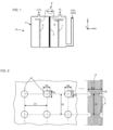
Figure 1 shows a schematic diagram of an example of an electrolysis device in which the promoted electrodes can be used, -
Figure 2 illustrates a detailed view of examples of surface patterns formed as recesses, with a front face view on the left side and a section view on the right side, -
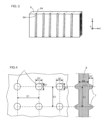
Figure 3 illustrates schematically a portion of an electrode with vertical grooves, -
Figure 4 illustrates a detailed view of examples of surface patterns formed as projections, with a front face view on the left side and a section view on the right side, -
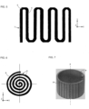
Figure 5 shows a section view of an example of an electrode body having a snake shape, -
Figure 6 shows a section view of an example of an electrode body having a spiral shape, -
Figure 7 illustrates a perspective view of an example of electrode having a cylindrical shape. - In the figures, the same references denote identical or similar elements. For the sake of clarity, various elements may not be represented at scale.
- Referring to
Figure 1 , the illustratedelectrolysis device 10 comprises acontainer 4. In the illustrated example, thecontainer 4 accommodates an aqueousalkaline solution 5. The aqueous alkaline solution is based on KOH (potassium hydroxide) wherein K+ and OH- ions convey electrical charges. The aqueous alkaline solution is strongly alkaline, namely the pH of the aqueous alkaline solution is > 13, preferably the pH is > 13,5. - The
electrolysis device 10 comprises a cathodic electrode 1 and ananodic electrode 2. - A current is selectively applied by an
electrical generator 9 between the cathodic electrode 1 and theanodic electrode 2. The electrolysis device is configured to produce hydrogen gas from water when theelectrical generator 9 applies a current density of at least 50 mA per cm2 which corresponds to a voltage of at most 1,9 V. As a reminder, a base activation voltage at starting currents is 1,23 V. Overvoltage atop 1,23 V is depending on Ohmic resistance and charge transfer (1,23 V corresponds to the standard oxidation potential for the H2O/O2 couple). A low overvoltage is beneficial to the efficiency of the electrolysis process. - In the illustrated example, the electrolysis device further comprises an
anion exchange membrane 3 separating the container into first and second portions, the cathodic electrode 1 being arranged in the first portion, and theanodic electrode 2 being arranged in the second portion. - As known per se, H2 is produced at the cathodic electrode. O2 is produced at the anodic electrode. As known per se, the half-reactions in both AEM and AWE electrolyzers are as follows:
Anode : 4 OH- (aq) → 2 H2O(l) + 4 e- + O2(g)
Cathode : 4 H2O(l) + 4 e- → 2 H2(g) + 4 OH- (aq)
- The
container 4 may be pressurized, such that Hz is outputted at the container pressure. Furthermore, H2 compression might be required to hold H2 in high pressure storage conditions. The pressure inside the container may be several bars or even several dozens of bars. - The cathodic electrode 1 is made of a nickel alloy, with a nickel base alloyed with at least one element chosen among chromium, molybdenum, cobalt and iron.
- The
anodic electrode 2 is also made of a nickel alloy, with a nickel base alloyed with at least one element chosen among chromium, molybdenum, cobalt and iron. - The cathodic electrode and the anodic electrode are manufactured thanks to an additive manufacturing process, for example via a Selective Laser Melting process from mixed metallic powder compounds.
- Selective Laser Melting process melt subsequent layers of powder, with a layer having a thickness of about 20 µm (micrometer).
- The cathodic electrode 1 is manufactured from a first mixed metallic powder compound. The first mixed metallic powder compound may comprise, in mass proportions, X percent of cobalt and 100-X % of nickel, resulting in a cathodic electrode made of NiCo alloy. Likewise, the first mixed metallic powder compound may comprise, X percent of molybdenum and 100-X % of nickel, resulting in a cathodic electrode made of NiMo alloy. For example, X may lie between 2 and 40. According to a peculiar example, X can be comprised between 8 and 12.
- A third chemical element can be added to the nickel base and the second chemical element (Co or Mo) to give a ternary alloy. Chromium can be used as such third element to be included in the mixed metallic powder compound. Therefore, the cathodic electrode can be made of a ternary alloy such as NiCoCr alloy or NiMoCr alloy. Percentage of Cr can be comprised between 1% and 10%.
- The
anodic electrode 2 is manufactured from a second mixed metallic powder compound. The second mixed metallic powder compound may comprise, in mass proportions, Y percent of iron and 100-Y % of nickel resulting in an anodic electrode made of NiFe alloy. Likewise, the second mixed metallic powder compound may comprise, Y percent of molybdenum and 100-Y % of nickel resulting in an anodic electrode made of NiMo alloy. - As for the cathodic electrode, the anodic electrode can be designed as a ternary alloy such as NiFeCr alloy or NiMoCr alloy. Percentage of Cr can be comprised between 1% and 10%.
- For example, Y lies between 2 and 40. According to a peculiar example, Y can be comprised between 6 and 14.
- Preparation of powder mixtures implies extensive mixing and stirring of the two or three powder components, such that the powder compound is highly homogeneous when introduced in the 3D SLM printer.
- The cathodic electrode 1 exhibits an outer surface comprising a plurality of first surface patterns. Similarly, the
anodic electrode 2 exhibits an outer surface comprising a plurality of first surface patterns.Figures 2 to 7 and their relative comments apply both to cathodic and anodic electrodes. - As illustrated in
Figure 2 , there may be provided recesses 6. Each surface pattern is a localized recess. - Each
recess 6 exhibits a recess depth H6 comprised between 0,1 mm and 0,4 mm. In preferred examples, the recess depth lies between 0,2 mm and 0,3 mm. Eachrecess 6 exhibits a base size, namely the circumscribed circle diameter D6 in the circular example. The base size D6 is comprised between 0,3 mm and 1 mm, preferably between 0,3 mm and 0,4 mm. Eachrecess 6 can have an inward conical shape, an inward frustoconical shape, an inverted pyramid shape, etc... The recess base may be circular or polygonal, without excluding other geometrical shapes. - The
recesses 6 are arranged in an array/matrix having a pitch E1 as depicted inFigures 2 and4 . The pitch E1 is comprised between 1 mm and 8 mm, preferably between 1 mm and 2,5 mm. A high density of surface patterns, here recesses, is therefore provided to maximize the number of bubble nucleation sites. Besides a regular array, the recesses can be arranged in staggered rows or else. - As illustrated in
Figure 3 , there may be providedgrooves 64. The groove depth is comprised between 0,1 mm and 0,4 mm. In some embodiments, neighboring grooves are spaced by a distance comprised between 1 mm and 3 mm. Thegroove 64 extends substantially vertically. Such grooves promote bubbles growth and bubbles upward evacuation. - As illustrated in
Figure 4 , there may be providedprojections 7. Each projection exhibits a projection height H7 comprised between 0,1 mm and 0,4 mm. Eachprojection 7 exhibits a base size, namely the circumscribed circle diameter D7 in the circular depicted example. - The base size D7 is comprised between 0,3 mm and 1 mm, preferably between 0,3 mm and 0,4 mm. Each
projection 7 can have an outward conical shape, a frustoconical shape, a pyramid shape, etc... The projection base may be circular or polygonal, without excluding other geometrical shapes. The arrangement and pitch E1 of the projections can be similar to what is discussed above for the recesses. - There may be provided linear projections, such as a rib (not illustrated) similar to the groove discussed above. The rib extends substantially in a vertical direction. The rib height is comprised between 0,1 mm and 0,4 mm.
- Each of the cathodic electrode and the anodic electrode comprises a number of recess and/or projections per cm2 comprised between 2 and 32, preferably between 16 and 32. A high density of surface patterns is therefore provided to maximize the number of bubble nucleation sites.
- Each of the cathodic electrode 1 and the
anodic electrode 2 comprises abody 8 with an outer surface from which the surface patterns take reference. In some embodiments, the body may have a thickness E8 comprised between 3 mm and 6 mm. Thicker or thinner bodies are also possible. - By contrast to
Figures 1 to 4 that show a planar electrode body,Figures 5 to 7 show other body shapes. Generally, thebody 8 may have a plate like shape or a cylindrical shape or a spiral shape or a coil/snake shape. - On the figures, Z denotes the vertical direction whereas X and Y denote two horizontal directions.
-
Figure 5 shows abody 8 having a coil/snake shape.Recesses 6 andprojections 7 are represented schematically in some regions on the left side, but of course, the entire surface of the body can be populated with recesses (or respectively projections 7). -
Figure 6 shows abody 8 having a spiral shape.Recesses 6 are represented schematically only in some regions, but of course, the entire surface of thebody 8 can be populated with recesses (or alternately projections). -
Figure 7 shows abody 8 having a cylindrical shape having an axis A. -
Vertical grooves 64 are distributed on all the outer surface. Grooves can also be arranged in the inner wall of the cylinder. - SLM 3D printing is advantageous over electrodeposition on moulded or machined body. More precisely, in the known art, in a first step, a body is fabricated by molding. Machining can be optionally applied to the body. Thereafter, the body is immersed in a liquid and an electrodeposition or a hydrothermal process is applied to the body. However, the thickness of the deposited layer is not perfectly mastered and depends on operational conditions. Further, if the body comprises small sized blind holes, deposition tends to overfill the small sized blind holes, therefore giving inhomogeneous deposition.
- By contrast, the promoted solution to obtain electrodes involves only one manufacturing step. It requires a CAD file to be inputted in the 3D printer, and the prescribed powder mixture. Small sized blind holes can be included in the CAD design. The accuracy of the resulting electrodes depends on the precision of the 3D printing machine. Small recesses as discussed above can be easily achieved with a good accuracy and a good repeatability.
- Regarding efficiency, each of the cathodic electrode 1 and the
anodic electrode 2 conveys an electric current density of at least 50 mA per cm2 of an overall electrode surface. - Thanks to the promoted electrodes, the inventors have generally achieved a sustained performance regarding energy efficiency of less than 55 kWh per kilogram H2. According to some embodiments of the present invention, an energy efficiency of less than 50 kWh per kilogram H2 is achieved.
- Electrodes can be used several hours, several days continuously without any physical or chemical alteration.
Claims (15)
- An electrolysis device configured to produce hydrogen gas from water,the electrolysis device comprising a container (4), the container accommodating an aqueous alkaline solution (5), a cathodic electrode (1), and an anodic electrode (2),an electrical current being selectively applied between the cathodic electrode and the anodic electrode,wherein the cathodic electrode is made of a nickel alloy, with a nickel base alloyed with at least one element chosen among chromium, molybdenum, cobalt and iron,wherein at least the cathodic electrode is manufactured by an additive manufacturing process, from a first mixed metallic powder compound, wherein the cathodic electrode exhibits an outer surface comprising a plurality of first surface patterns (6,7).
- The electrolysis device according to claim 1, wherein also the anodic electrode is made of a nickel alloy, with a nickel base alloyed with at least one element chosen among chromium, molybdenum, cobalt and iron, and wherein the anodic electrode is manufactured by an additive manufacturing process, from a second mixed metallic powder compound, wherein the anodic electrode exhibits an outer surface comprising a plurality of second surface patterns.
- The electrolysis device according to claim 2, wherein the cathodic electrode and the anodic electrode are manufactured via a Selective Laser Melting process, from respectively the first and second mixed metallic powder compounds.
- The electrolysis device according to claim 1, wherein the first mixed metallic powder compound comprises, in mass proportions, X percent of cobalt or molybdenum and 100-X % of nickel, resulting in a cathodic electrode made of NiCo or NiMo alloy.
- The electrolysis device according to claim 2, wherein the second mixed metallic powder compound comprises, in mass proportions, Y percent of iron or molybdenum and 100-Y % of nickel resulting in an anodic electrode made of NiFe alloy or NiMo alloy.
- The electrolysis device according to any of the claims 1 to 5, wherein each surface pattern is a localized or individualized surface pattern, preferably each surface pattern is a recess (6).
- The electrolysis device according to claim 6, wherein each recess exhibits a recess depth (H6) comprised between 0,1 mm and 0,4 mm, preferably between 0,2 mm and 0,3 mm.
- The electrolysis device according to any of the claims 6 to 7, wherein each recess exhibits a base size, such as a circumscribed circle diameter, (D6) comprised between 0,3 mm and 1 mm, preferably between 0,3 mm and 0,4 mm.
- The electrolysis device according to any of the claims 6 to 8, wherein on each of the cathodic electrode and the anodic electrode, the recesses are arranged in an array/matrix having a pitch (E1) comprised between 1 mm and 8 mm, preferably between 1 mm and 2.5 mm.
- The electrolysis device according to any of the claims 1 to 5, wherein there is provided one or more linearly extending grooves (64).
- The electrolysis device according to any of the claims 1 to 5, wherein each surface pattern is a localized or individualized projection (7).
- The electrolysis device according to any of the claims 2 to 11, wherein each of the cathodic electrode and the anodic electrode comprises a number of recesses and/or projections per cm2 comprised between 2 and 32, preferably between 16 and 32.
- The electrolysis device according to any of the claims 2 to 12, wherein each of the cathodic electrode and the anodic electrode conveys an electric current corresponding to a minimum of 50 mA per cm2 of an overall electrode surface.
- The electrolysis device according to any of the claims 2 to 13, wherein each of the cathodic electrode and the anodic electrode comprises a body (8) with an outer surface from which the surface patterns take reference, the body having a plate like shape or a cylindrical shape or a spiral shape or a coil or snake shape.
- The electrolysis device according to any of the claims 2 to 14, further comprising an anion exchange membrane (3) separating the container into first and second portions, the cathodic electrode being arranged in the first portion, and the anodic electrode being arranged in the second portion.
Priority Applications (2)
| Application Number | Priority Date | Filing Date | Title |
|---|---|---|---|
| EP23315446.7A EP4563350A1 (en) | 2023-12-01 | 2023-12-01 | Electrolyser with nickel alloy 3d printed electrode |
| PCT/EP2024/084169 WO2025114571A1 (en) | 2023-12-01 | 2024-11-29 | Electrolyser with nickel alloy 3d printed electrode |
Applications Claiming Priority (1)
| Application Number | Priority Date | Filing Date | Title |
|---|---|---|---|
| EP23315446.7A EP4563350A1 (en) | 2023-12-01 | 2023-12-01 | Electrolyser with nickel alloy 3d printed electrode |
Publications (1)
| Publication Number | Publication Date |
|---|---|
| EP4563350A1 true EP4563350A1 (en) | 2025-06-04 |
Family
ID=89474772
Family Applications (1)
| Application Number | Title | Priority Date | Filing Date |
|---|---|---|---|
| EP23315446.7A Pending EP4563350A1 (en) | 2023-12-01 | 2023-12-01 | Electrolyser with nickel alloy 3d printed electrode |
Country Status (2)
| Country | Link |
|---|---|
| EP (1) | EP4563350A1 (en) |
| WO (1) | WO2025114571A1 (en) |
Citations (3)
| Publication number | Priority date | Publication date | Assignee | Title |
|---|---|---|---|---|
| US20220290319A1 (en) * | 2019-09-05 | 2022-09-15 | Thyssenkrupp Uhde Chlorine Engineers Gmbh | Cross-flow water electrolysis |
| CN115613049A (en) * | 2022-10-17 | 2023-01-17 | 西北工业大学 | A high-efficiency water-splitting electrode based on 3D printing nickel-iron alloy and its preparation method |
| CN116555800A (en) * | 2023-05-24 | 2023-08-08 | 北京工业大学 | A self-supporting electrode for electrocatalytic water splitting and its preparation method |
-
2023
- 2023-12-01 EP EP23315446.7A patent/EP4563350A1/en active Pending
-
2024
- 2024-11-29 WO PCT/EP2024/084169 patent/WO2025114571A1/en active Pending
Patent Citations (3)
| Publication number | Priority date | Publication date | Assignee | Title |
|---|---|---|---|---|
| US20220290319A1 (en) * | 2019-09-05 | 2022-09-15 | Thyssenkrupp Uhde Chlorine Engineers Gmbh | Cross-flow water electrolysis |
| CN115613049A (en) * | 2022-10-17 | 2023-01-17 | 西北工业大学 | A high-efficiency water-splitting electrode based on 3D printing nickel-iron alloy and its preparation method |
| CN116555800A (en) * | 2023-05-24 | 2023-08-08 | 北京工业大学 | A self-supporting electrode for electrocatalytic water splitting and its preparation method |
Non-Patent Citations (1)
| Title |
|---|
| XU QIUCHENG ET AL: "Anion Exchange Membrane Water Electrolyzer: Electrode Design, Lab-Scaled Testing System and Performance Evaluation", ENERGYCHEM, vol. 4, no. 5, 1 September 2022 (2022-09-01), pages 100087, XP093128778, ISSN: 2589-7780, Retrieved from the Internet <URL:https://dx.doi.org/10.1016/j.enchem.2022.100087> DOI: 10.1016/j.enchem.2022.100087 * |
Also Published As
| Publication number | Publication date |
|---|---|
| WO2025114571A1 (en) | 2025-06-05 |
Similar Documents
| Publication | Publication Date | Title |
|---|---|---|
| Li et al. | Low-temperature water electrolysis: fundamentals, progress, and new strategies | |
| KR102123840B1 (en) | Unitizied bipolar plate with electrodes for water electolysis and water electrolyzer | |
| Hudkins et al. | Rapid prototyping of electrolyzer flow field plates | |
| US10619255B2 (en) | Anode for alkaline water electrolysis and method for producing anode for alkaline water electrolysis | |
| US6872286B2 (en) | Water electrolysis cell | |
| Vidales et al. | Evaluation of nickel-molybdenum-oxides as cathodes for hydrogen evolution by water electrolysis in acidic, alkaline, and neutral media | |
| Zhang et al. | Hydrogen production by traditional and novel alkaline water electrolysis on nickel or iron based electrocatalysts | |
| Guo et al. | Direct electrodeposition of Ni‐Co‐S on carbon paper as an efficient cathode for anion exchange membrane water electrolysers | |
| CN105780050A (en) | Preparing method for phosphate group Ni-Fe hydroxide doped nano-film catalyst used for decomposing water | |
| KR20150104474A (en) | Alkaline anion exchange membrane water electrolyzer using Ni electrodeposited hydrophilic porous carbon material and method for preparing the same | |
| KR102556499B1 (en) | Bifunctional electrocatalysts for OER and HER comprising cobalt phosphide and platinum, and substrate comprising the same | |
| Zhao et al. | Process kinetics for the electrocatalytic hydrogen evolution reaction on carbon-based Ni/NiO nanocomposite in a single-chamber microbial electrolysis cell | |
| Yeon et al. | Electrodeposited nickel phosphide supported by copper foam for proton exchange membrane water electrolyzer | |
| Wang et al. | From laboratory to industrial scale: nickel-based catalysts for hydrogen evolution under highcurrent–density alkaline electrolysis: WW Wang et al | |
| Kublanovsky et al. | Electrocatalytic properties of molybdenum and tungsten alloys in the hydrogen evolution reaction | |
| Lavorante et al. | Straight‐parallel electrodes and variable gap for hydrogen and oxygen evolution reactions | |
| WO2025114571A1 (en) | Electrolyser with nickel alloy 3d printed electrode | |
| Phillips et al. | Zero gap cell design for alkaline electrolysis | |
| Ghouri et al. | Hydrogen production from seawater electrolysis | |
| KR102390091B1 (en) | Development of efficient electrocatalyst using multicomponent base metal alloys | |
| JP2007046130A (en) | Electrolytic hydrogen production system and production method thereof | |
| Gonsalves et al. | Electrochemical water electrolysis using electrodeposited (NiMo) coatings from a low concentration bath | |
| CN116508180A (en) | Components for electrochemical cells as well as redox flow battery cells, fuel cell cells and electrolyzers | |
| Zhang et al. | Noble-metal-free OER electrocatalysts working at high current densities over | |
| US20240368783A1 (en) | Electrolyzer electrocatalyst comprising cobalt (co) oxide, zirconium (zr) and a noble metal, an electrode comprising the electrocatalyst and the use of the electrocatalyst in an electrolysis process |
Legal Events
| Date | Code | Title | Description |
|---|---|---|---|
| PUAI | Public reference made under article 153(3) epc to a published international application that has entered the european phase |
Free format text: ORIGINAL CODE: 0009012 |
|
| STAA | Information on the status of an ep patent application or granted ep patent |
Free format text: STATUS: THE APPLICATION HAS BEEN PUBLISHED |
|
| AK | Designated contracting states |
Kind code of ref document: A1 Designated state(s): AL AT BE BG CH CY CZ DE DK EE ES FI FR GB GR HR HU IE IS IT LI LT LU LV MC ME MK MT NL NO PL PT RO RS SE SI SK SM TR |
|
| STAA | Information on the status of an ep patent application or granted ep patent |
Free format text: STATUS: REQUEST FOR EXAMINATION WAS MADE |
|
| 17P | Request for examination filed |
Effective date: 20251204 |