EP4563316A2 - Wire harness connector boot molding - Google Patents
Wire harness connector boot molding Download PDFInfo
- Publication number
- EP4563316A2 EP4563316A2 EP24216305.3A EP24216305A EP4563316A2 EP 4563316 A2 EP4563316 A2 EP 4563316A2 EP 24216305 A EP24216305 A EP 24216305A EP 4563316 A2 EP4563316 A2 EP 4563316A2
- Authority
- EP
- European Patent Office
- Prior art keywords
- outer shell
- connector
- hole
- inner shells
- molding system
- Prior art date
- Legal status (The legal status is an assumption and is not a legal conclusion. Google has not performed a legal analysis and makes no representation as to the accuracy of the status listed.)
- Pending
Links
Images





Classifications
-
- B—PERFORMING OPERATIONS; TRANSPORTING
- B29—WORKING OF PLASTICS; WORKING OF SUBSTANCES IN A PLASTIC STATE IN GENERAL
- B29C—SHAPING OR JOINING OF PLASTICS; SHAPING OF MATERIAL IN A PLASTIC STATE, NOT OTHERWISE PROVIDED FOR; AFTER-TREATMENT OF THE SHAPED PRODUCTS, e.g. REPAIRING
- B29C33/00—Moulds or cores; Details thereof or accessories therefor
- B29C33/38—Moulds or cores; Details thereof or accessories therefor characterised by the material or the manufacturing process
- B29C33/3842—Manufacturing moulds, e.g. shaping the mould surface by machining
-
- B—PERFORMING OPERATIONS; TRANSPORTING
- B29—WORKING OF PLASTICS; WORKING OF SUBSTANCES IN A PLASTIC STATE IN GENERAL
- B29C—SHAPING OR JOINING OF PLASTICS; SHAPING OF MATERIAL IN A PLASTIC STATE, NOT OTHERWISE PROVIDED FOR; AFTER-TREATMENT OF THE SHAPED PRODUCTS, e.g. REPAIRING
- B29C33/00—Moulds or cores; Details thereof or accessories therefor
- B29C33/30—Mounting, exchanging or centering
- B29C33/301—Modular mould systems [MMS], i.e. moulds built up by stacking mould elements, e.g. plates, blocks, rods
-
- B—PERFORMING OPERATIONS; TRANSPORTING
- B29—WORKING OF PLASTICS; WORKING OF SUBSTANCES IN A PLASTIC STATE IN GENERAL
- B29B—PREPARATION OR PRETREATMENT OF THE MATERIAL TO BE SHAPED; MAKING GRANULES OR PREFORMS; RECOVERY OF PLASTICS OR OTHER CONSTITUENTS OF WASTE MATERIAL CONTAINING PLASTICS
- B29B11/00—Making preforms
- B29B11/06—Making preforms by moulding the material
- B29B11/08—Injection moulding
-
- B—PERFORMING OPERATIONS; TRANSPORTING
- B29—WORKING OF PLASTICS; WORKING OF SUBSTANCES IN A PLASTIC STATE IN GENERAL
- B29C—SHAPING OR JOINING OF PLASTICS; SHAPING OF MATERIAL IN A PLASTIC STATE, NOT OTHERWISE PROVIDED FOR; AFTER-TREATMENT OF THE SHAPED PRODUCTS, e.g. REPAIRING
- B29C33/00—Moulds or cores; Details thereof or accessories therefor
- B29C33/0011—Moulds or cores; Details thereof or accessories therefor thin-walled moulds
-
- B—PERFORMING OPERATIONS; TRANSPORTING
- B29—WORKING OF PLASTICS; WORKING OF SUBSTANCES IN A PLASTIC STATE IN GENERAL
- B29C—SHAPING OR JOINING OF PLASTICS; SHAPING OF MATERIAL IN A PLASTIC STATE, NOT OTHERWISE PROVIDED FOR; AFTER-TREATMENT OF THE SHAPED PRODUCTS, e.g. REPAIRING
- B29C33/00—Moulds or cores; Details thereof or accessories therefor
- B29C33/12—Moulds or cores; Details thereof or accessories therefor with incorporated means for positioning inserts, e.g. labels
-
- B—PERFORMING OPERATIONS; TRANSPORTING
- B29—WORKING OF PLASTICS; WORKING OF SUBSTANCES IN A PLASTIC STATE IN GENERAL
- B29C—SHAPING OR JOINING OF PLASTICS; SHAPING OF MATERIAL IN A PLASTIC STATE, NOT OTHERWISE PROVIDED FOR; AFTER-TREATMENT OF THE SHAPED PRODUCTS, e.g. REPAIRING
- B29C33/00—Moulds or cores; Details thereof or accessories therefor
- B29C33/30—Mounting, exchanging or centering
- B29C33/306—Exchangeable mould parts, e.g. cassette moulds, mould inserts
-
- B—PERFORMING OPERATIONS; TRANSPORTING
- B29—WORKING OF PLASTICS; WORKING OF SUBSTANCES IN A PLASTIC STATE IN GENERAL
- B29C—SHAPING OR JOINING OF PLASTICS; SHAPING OF MATERIAL IN A PLASTIC STATE, NOT OTHERWISE PROVIDED FOR; AFTER-TREATMENT OF THE SHAPED PRODUCTS, e.g. REPAIRING
- B29C39/00—Shaping by casting, i.e. introducing the moulding material into a mould or between confining surfaces without significant moulding pressure; Apparatus therefor
- B29C39/22—Component parts, details or accessories; Auxiliary operations
- B29C39/24—Feeding the material into the mould
-
- B—PERFORMING OPERATIONS; TRANSPORTING
- B60—VEHICLES IN GENERAL
- B60R—VEHICLES, VEHICLE FITTINGS, OR VEHICLE PARTS, NOT OTHERWISE PROVIDED FOR
- B60R16/00—Electric or fluid circuits specially adapted for vehicles and not otherwise provided for; Arrangement of elements of electric or fluid circuits specially adapted for vehicles and not otherwise provided for
- B60R16/02—Electric or fluid circuits specially adapted for vehicles and not otherwise provided for; Arrangement of elements of electric or fluid circuits specially adapted for vehicles and not otherwise provided for electric constitutive elements
- B60R16/0207—Wire harnesses
- B60R16/0215—Protecting, fastening and routing means therefor
-
- H—ELECTRICITY
- H01—ELECTRIC ELEMENTS
- H01R—ELECTRICALLY-CONDUCTIVE CONNECTIONS; STRUCTURAL ASSOCIATIONS OF A PLURALITY OF MUTUALLY-INSULATED ELECTRICAL CONNECTING ELEMENTS; COUPLING DEVICES; CURRENT COLLECTORS
- H01R13/00—Details of coupling devices of the kinds covered by groups H01R12/70 or H01R24/00 - H01R33/00
- H01R13/46—Bases; Cases
- H01R13/516—Means for holding or embracing insulating body, e.g. casing, hoods
-
- H—ELECTRICITY
- H01—ELECTRIC ELEMENTS
- H01R—ELECTRICALLY-CONDUCTIVE CONNECTIONS; STRUCTURAL ASSOCIATIONS OF A PLURALITY OF MUTUALLY-INSULATED ELECTRICAL CONNECTING ELEMENTS; COUPLING DEVICES; CURRENT COLLECTORS
- H01R43/00—Apparatus or processes specially adapted for manufacturing, assembling, maintaining, or repairing of line connectors or current collectors or for joining electric conductors
- H01R43/18—Apparatus or processes specially adapted for manufacturing, assembling, maintaining, or repairing of line connectors or current collectors or for joining electric conductors for manufacturing bases or cases for contact members
-
- H—ELECTRICITY
- H01—ELECTRIC ELEMENTS
- H01R—ELECTRICALLY-CONDUCTIVE CONNECTIONS; STRUCTURAL ASSOCIATIONS OF A PLURALITY OF MUTUALLY-INSULATED ELECTRICAL CONNECTING ELEMENTS; COUPLING DEVICES; CURRENT COLLECTORS
- H01R43/00—Apparatus or processes specially adapted for manufacturing, assembling, maintaining, or repairing of line connectors or current collectors or for joining electric conductors
- H01R43/20—Apparatus or processes specially adapted for manufacturing, assembling, maintaining, or repairing of line connectors or current collectors or for joining electric conductors for assembling or disassembling contact members with insulating base, case or sleeve
- H01R43/24—Assembling by moulding on contact members
-
- B—PERFORMING OPERATIONS; TRANSPORTING
- B29—WORKING OF PLASTICS; WORKING OF SUBSTANCES IN A PLASTIC STATE IN GENERAL
- B29K—INDEXING SCHEME ASSOCIATED WITH SUBCLASSES B29B, B29C OR B29D, RELATING TO MOULDING MATERIALS OR TO MATERIALS FOR MOULDS, REINFORCEMENTS, FILLERS OR PREFORMED PARTS, e.g. INSERTS
- B29K2883/00—Use of polymers having silicon, with or without sulfur, nitrogen, oxygen, or carbon only, in the main chain, as mould material
- B29K2883/005—LSR, i.e. liquid silicone rubbers, or derivatives thereof
-
- B—PERFORMING OPERATIONS; TRANSPORTING
- B29—WORKING OF PLASTICS; WORKING OF SUBSTANCES IN A PLASTIC STATE IN GENERAL
- B29L—INDEXING SCHEME ASSOCIATED WITH SUBCLASS B29C, RELATING TO PARTICULAR ARTICLES
- B29L2031/00—Other particular articles
- B29L2031/34—Electrical apparatus, e.g. sparking plugs or parts thereof
- B29L2031/36—Plugs, connectors, or parts thereof
Definitions
- the application relates generally to wire harnesses and, more particularly, to a system and a method for molding a connector boot over a connector of a wire harness.
- Wiring harnesses also know as cable harnesses or wiring harnesses, mounted to aircraft engines are subject to various sources of stress including: vibrations, thermal cycles to name a few. Over time, wire connector boots can crack and or be otherwise damaged necessitating repair or replacement. Connector boots can also be damaged during handling, including installation or removal.
- a molding system for molding a connector boot over a connector of a wire harness comprising a mold assembly including an outer shell having a first outer shell part and a second outer shell part configured to be assembled together around the wire harness, the first and second outer shell parts defining an internal cavity bounded by a cavity surface; and interchangeable inner shells selectively removably positionable in the internal cavity of the outer shell, the interchangeable inner shells having an outer surface geometry that is complementary to a geometry of the cavity surface of the internal cavity of the outer shell, and different inner surface geometries corresponding to respective outer surface geometries of different connector boot models.
- a molding system for forming a molded component over a wire harness, the molding system comprising: an outer shell comprising a pair of metallic shell halves configured to be joined together to define a mold cavity around the wire harness, the mold cavity bounded by a cavity surface; interchangeable inner shells removably positionable in the mold cavity, each of the interchangeable inner shells comprising a pair of silicon shell halves, the interchangeable inner shells having an outer surface that is a positive of the cavity surface of the mold cavity of the outer shell, wherein a first inner shell of the interchangeable inner shells has a first inner surface geometry, wherein a second inner shell of the interchangeable inner shells has a second inner surface geometry, and wherein the first inner surface geometry is different from the second inner surface geometry.
- a molding system comprising an outer shell having a pair of shell halves configured to be joined together to define a mold cavity, the mold cavity bounded by a cavity surface; interchangeable inner shells removably positionable in the mold cavity, each of the interchangeable inner shells comprising a pair of shell halves, the interchangeable inner shells having an outer surface that is a positive of the cavity surface of the mold cavity of the outer shell, wherein a first inner shell of the interchangeable inner shells has a first inner surface geometry, wherein a second inner shell of the interchangeable inner shells has a second inner surface geometry, and wherein the first inner surface geometry is different from the second inner surface geometry.
- the molding system further comprises dummy connectors selectively positionable in the internal cavity of the outer shell for molding respective ones of the interchangeable inner shells, the dummy connectors each including: a main body having a connector boot portion receivable in the internal cavity, a cable portion and a connector portion, the connector portion and the cable portion configured to respectively extend through and seal a corresponding connector hole and a corresponding cable hole in the outer shell.
- the outer shell has an inner shell injection hole for injecting a first resin into the internal cavity of the outer shell around a selected one of the dummy connectors, and a connector boot injection port engaged with a fitting defining a connector boot injection hole for injecting a second resin in the internal cavity for molding the connector boot over the connector of the wire harness, and wherein each of the dummy connectors further has a connector boot plug extending from the main body to plug the connector boot injection hole during molding of a selected one of the interchangeable inner shells, the connector boot plug configured to form an injection hole in the selected one of the interchangeable inner shells.
- the outer shell has first and second overflow holes
- each of the dummy connectors has an overflow hole plug extending from the main body to plug the first overflow hole of the outer shell during the molding of the selected one of the interchangeable inner shells, the overflow hole plug configured to form a third overflow hole in the selected one of the interchangeable inner shells.
- the outer shell has a connector hole and a cable hole for respectively accommodating a connector portion and a cable portion of the wire harness, the connector hole extending centrally through a cylindrical protrusion extending outwardly from the outer shell, and wherein the mold assembly further comprises: a cap rotatably engageable with the cylindrical protrusion, the cap rotatably connectable to the connector of the wire harness, and a dial to allow the cap to be rotated to a desired angular position, the dial including an angular scale and a pointer provided on respective ones of the outer shell and the cap.
- the angular scale comprises a circular clocking scale including angle markings from 0 degrees to 360 degrees provided on the outer shell around the cylindrical protrusion, the pointer provided in the form of a visual mark on an outer cylindrical surface of the cap.
- fasteners are provided for releasably securing the cap in the desired angular position on the cylindrical protrusion.
- the fasteners include set screws threadedly engaged in respective side holes defined in the cap for engagement with an outer surface of the cylindrical protrusion.
- the cap defines a drive socket for rotatably drivingly engaging the connector.
- the outer shell has a first cable hole, a second cable hole, and a connector hole, wherein the first cable hole and the connector hole are axially aligned along a straight line and disposed on opposed first and second parallel sides of the outer shell, the second cable hole disposed on a third side of the outer shell perpendicular to the first and second parallel sides, the second cable hole extending along an axis perpendicular to the straight line, and wherein the mold assembly further comprises a plug to plug a selected one of the first cable hole and the second cable hole.
- the molding system further comprises: a syringe fluidly connected to a or the fitting engaged with the connector boot injection port defined in a bottom surface of the outer shell of the mold assembly; a syringe pump operatively connected to the syringe; and a fixture comprising a retaining mechanism for holding the mold assembly, the retaining mechanism articulated to a column.
- the column extends upwardly from a base, the base including a table clamp configured for releasably securing the fixture to a table.
- the outer shell is a metal outer shell
- the interchangeable inner shells are silicon inner shells, the metal outer shell and the silicon inner shells having registering injection holes (and/or ports) and overflow holes respectively defined in a bottom wall and an opposed upper wall thereof.
- the outer shell is a metal outer shell
- the interchangeable inner shells are silicon inner shells
- the metal outer shell has a or the connector boot injection port defined in a bottom wall thereof and in register with an injection hole defined in a bottom wall of the silicon inner shells
- the metal outer shell has an or the overflow hole defined in an upper wall thereof opposed to the bottom wall of the metal outer shell, the overflow hole of the metal outer shell in register with an overflow hole of the silicon inner shells defined in an upper wall opposed to the bottom wall of the silicon inner shells.
- the outer shell is a metal outer shell
- the interchangeable inner shells are silicon inner shells
- the metal outer shell has a or the connector boot injection port defined in a bottom wall thereof and engaged with a fitting defining a or the connector boot injection hole
- the connector boot injection hole in register with an injection hole defined in a bottom wall of the silicon inner shells
- the metal outer shell has an or the overflow hole defined in an upper wall thereof opposed to the bottom wall of the metal outer shell, the overflow hole of the metal outer shell in register with an overflow hole of the silicon inner shells defined in an upper wall opposed to the bottom wall of the silicon inner shells.
- the connector hole has an annular inner shoulder configured to form a seat for a corresponding outer shoulder on the connector of the wire harness, the seat facing outside of the internal cavity of the outer shell.
- the molding system further comprises a dummy connector, the dummy connector having a main body which has an outer geometry based on the design specifications of a connector of the wire harness, the dummy connector positionable in the mold cavity for molding the first inner shell of the interchangeable inner shells within the outer shell, the dummy connector including a first arm extending upwardly from the main body to produce an overflow hole in a top surface of the first inner shell, and a second arm extending downwardly from the main body to produce an injection hole in a bottom surface of the first inner shell, the injection hole and the overflow hole of the first inner shell respectively registering with a corresponding injection hole (and/or port) and a corresponding overflow hole in the outer shell.
- the dummy connector further a third arm projecting from the main body, the third arm configured to form a cable hole in the first inner shell, the cable hole configured for accommodating a cable portion of the wire harness.
- the outer shell has a connector hole configured for accommodating a connector of the wire harness, the connector hole extending through a cylindrical projection extending from an outer surface of the outer shell, and wherein the molding system further comprises a cap rotatably engaged on the cylindrical projection, the cap having a socket configured for driving engagement with the connector of the wire harness.
- a scale comprising angular markings is provided around the cylindrical projection on the outer surface of the outer shell, and wherein an indicator mark is provided on an outer cylindrical surface of the cap for alignment with a predetermined one of the angular markings on the outer shell.
- set screws are threadedly engaged with corresponding threaded holes extending through the cap for engagement with the cylindrical projection, the set screws operable for releasably securing the cap to the cylindrical projection.
- Fig. 1 illustrates a wire harness A having a cable B including a bundle of wires connected to a connector C that is, in turn, configured for connection with a receptacle or mating connector D of a piece of equipment, such as an aircraft engine component E, to transfer electrical power, signals or data.
- a connector boot F is molded over the connector C of the wire harness A to provide strain relief and increase the attachment between the cable B and the connector C.
- the connector boot F is molded from a suitable resin material (e.g., epoxy), which once fully cured, is adapted to withstand the environmental conditions in which the wire harness A is to be installed and provide sufficient strength to effectively limit the bend radius of the wire harness A and prevent damages caused by kinking or snagging, impacts, vibrations, pressure and temperature to name a few.
- the mating connectors C and D may be provided with alignment/keying features to prevent mating in an incorrect orientation.
- a first one of the connectors e.g., the wire harness connector C
- the connector C of the exemplified wire harness A is a right-angle connector.
- the connector C could have other configurations.
- the connector of the wire harness could be a linear/straight connector.
- Fig. 2 illustrates parts of a molding system 10 suitable for molding a connector boot over the connector of a wire harness, such as the wire harness A exemplified in Fig. 1 .
- the system 10 generally comprises a mold assembly 12 having an outer shell 14 and a set of interchangeable inner shells 16a, 16b, 16c...(only 3 sets of inner shells being illustrated for brevity) selectively removably positionable in a complementary fashion inside the outer shell 14, the inner shells 16a, 16b, 16c... having different internal surface geometries for molding different geometries of connector boots in a same base mold (i.e., in the same outer shell 14).
- the mold assembly 12 facilitates the change of connector boot form/geometry to be molded without changing the entire mold. That is different connector boot models/geometries can be molded over different wire harnesses using the same base mold.
- Such a mold assembly with interchangeable inner shells uses lesser tools, requires the handling of lesser parts and consequently generates economic savings.
- the outer shell 14 of the mold assembly 12 may be provided in the form of a rigid metal shell comprising a first outer shell part and a second outer shell part configured to be assembled together around the connector C of the wire harness A.
- the first and second outer shell parts respectively correspond to the bottom half 14a and the top half 14b of the outer shell 14 (i.e., the outer shell 14 is divided into two halves adapted to be assembled along a median horizontal parting line).
- the bottom and top halves 14a, 14b of the outer shell 14 define an internal cavity 14c bounded by a cavity surface 14d.
- each inner shell 16a, 16b, 16c... can be removably received in a unique position as a lining over the cavity surface 14d of the outer shell 14.
- the interchangeable inner shells 16a, 16b, 16c... can be molded inside the outer shell 14.
- dummy connectors are selectively positioned in the internal cavity 14c of the outer shell 14 for molding respective ones of the interchangeable inner shells 16a, 16b, 16c...
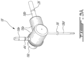
- Fig. 3a illustrates an example of such a dummy connector 18.
- the exemplified dummy connector 18 has a main body, which replicates the geometry/shape of the wire harness connector C over which the connector boot F is to be molded. That is the main body of the dummy connector 18 has the same outer geometrical features/outline as the connector C over which the connector boot F will be molded.
- the dummy connector 18 can be created by any suitable means.
- the dummy connector 18 can be machined from a solid block of material, such as aluminum, based on measurements taken from an existing connector of a wire harness or from a CAD model generated from the design specifications of the original connector.
- the model created with CAD can be manufactured as a physical component using any suitable manufacturing processes, such as CNC machining, 3D printing, additive manufacturing or any other suitable manufacturing processes.
- the dummy connector 18 illustrated in Fig. 3a is based on the design specifications of a right-angle connector. However, it is understood that the same principles could be applied to other angularly oriented connectors, including linear/straight connectors and 45 degrees connectors to name a few.
- the main body of the exemplified connector 18 comprises a connector boot portion 18a (i.e., the portion of the connector over which the connector boot is to be molded), a cable portion 18b extending from a cable side of the connector boot portion 18a and a connector portion 18c extending from the connector contact side of the connector boot portion 18a.
- the cable portion 18b and the connector portion 18c respectively correspond to a portion of the cable B extending from the right-angle connector C and to the connecting end portion of the connector C projecting out from the connector boot F on the wire harness A shown in Fig. 1 .
- the cable portion 18b and the connector portion 18c of the dummy connector 18 are respectively received in corresponding cable and connector holes 20 and 22 defined in the outer shell 14.
- the cable hole 20 and the connector hole 22 are defined in two different orthogonal sides of the outer shell 14. According to some embodiments and as shown in Figs.
- the outer shell 14 can be provided with a second cable hole 21 that is axially aligned with the connector hole 22, thereby allowing the same outer shell 14 to be used for both linear and right-angle connector applications.
- the mold assembly 12 may further comprise a cable hole plug 24 to plug the unused cable hole (i.e., the right-angle cable hole 20 or the straight cable hole 21) of the outer shell 14 during molding.
- the parting plane of the bottom and top halves 14a, 14b of the outer shell 14 extends centrally through the cable and connector holes 20, 21 and 22 (i.e., a first half of the cable and connector holes is defined in the bottom half 14a of the outer shell 14 and a second haft of the cable and connector holes is defined in the top half 14b of the outer shell 14).
- O-rings 26 may be provided on the cable portion 18b and the connector portion 18c of the dummy connector 18 to seal the cable and connector holes 20, 21 and 22 during molding of the inner shell 16a, 16b, 16c...
- Other suitable sealing arrangements are contemplated.
- the cable portion 18b and the connector portion 18c of the dummy connector 18 act as support arms for supporting the connector boot portion 18a in the internal cavity 14c of the outer shell 14.
- the cable portion 18b and the connector portion 18c can be integral to the connector boot portion 18a or detachably mounted thereto.
- the dummy connector 18 further comprises a connector boot injection hole plug or first arm 18d extending downwardly from the connector boot portion 18a of the main body of the dummy connector 18 to plug an injection hole 28 defined in a fitting 30 threadedly engaged in a connector boot injection port 32 defined in a bottom wall 34 of the bottom half 14a of the outer shell 14. It can be appreciated that the arm 18d will form an injection hole in the inner shell 16a after the same has been molded over the dummy connector 18. As shown in Figs.
- an O-ring 36 can be provided on the first arm 18d to enhance sealing of the injection hole 28 of the fitting 30 from the internal cavity 14c of the outer shell 14 during the molding of the inner shell 16a.
- the first arm 18d can be threadedly mounted or otherwise detachably connected to the connector boot portion 18a of the main body of the dummy connector 18.
- the dummy connector 18 further comprises an overflow hole plug or second arm 18e extending upwardly from the connector boot portion 18a of the main body of the dummy connector 18 for plugging a first overflow hole 40 defined in a top wall 42 of the top half 14b of the outer shell 14. It can be appreciated that this second arm 18e will produce an overflow hole in the inner shell 16a after the same has been molded in the outer shell 14 over the dummy connector 18.
- An O-ring 44 may be provided on the second arm 18e to better seal the overflow hole 40 during molding of the inner shell 16a.
- the second arm 18e can be threadedly mounted or otherwise detachably connected to the connector boot portion 18a of the main body of the dummy connector 18.
- the dummy connector 18 is positioned on the bottom half 14a of the outer shell 14 with the cable portion 18b and the connector portion 18c respectively resting on the bottom half of the cable hole 20 and the connector hole 22 and with the first arm 18d of the dummy connector 18 engaged in the connector boot injection hole 28 of the injection fitting 30.
- the plug 24 is also positioned in the bottom half of the unused cable hole 21.
- the top half 14b of the outer shell 14 is seated on top of the bottom half 14a of the outer shell 14 with the second arm 18e of the dummy connector 18 extending into the overflow hole 40, and the two outer shell halves 14a, 14b are clamped together to imprison the connector boot portion 18a of the dummy connector 18 within the internal cavity of the outer shell 14.
- Dowel pins or the like may be provided at the mounting interface of the bottom and top halves 14a, 14b of the outer shell 14 to ensure proper alignment.
- the dowel pins may be mounted in corresponding holes defined in the parting plane of the bottom and top halves 14a, 14b of the outer shell 14.
- the resin e.g., the silicon resin
- the resin is allowed to cure to form the inner shell 16a around the dummy connector 18 and then the outer shell 14 is opened.
- the molded inner shell 16a is retrieved from the outer shell 14 and cut in half, thereby providing bottom and top inner shell halves 16a', 16a" respectively positionable in a complementary fashion inside the bottom and top outer shell halves 14a, 14b for the subsequent molding of the connector boot F over the connector C of the wire harness A.
- the so produced inner shell 16a has an injection hole/passage 52 and an overflow hole 54 which are respectively aligned in registry with the corresponding connector boot injection hole 28 and the overflow hole 40 of the outer shell 14. In this way, the inner shell and the outer shell halves may be assembled together to form a mold assembly to mold a connector boot F over a given model of connector of virtually any wire harnesses.
- the molding system 10 further comprises a cap 60 having a clocking feature to angularly adjust the position of the keying/aligning features (such as the exemplified key G and keyway H of mating connectors C and D illustrated in Fig. 1 ) of connectors of wiring harnesses prior to molding connector boots over the connectors.
- the cap 60 is rotatably engageable over a cylindrical hollow protrusion or neck 62 projecting outwardly from the outer shell 14 centrally around the connector hole 22 in which the connector C of the wire harness A is to be positioned for the molding of the connector boot F, as shown in Fig. 4A .
- the cap 60 has a polygonal socket 64 (a square socket in the illustrated example) defined in one end thereof for driving engagement with a mating polygonal flange 66 (a square flange in the illustrated example) of a connector/receptacle corresponding to the connector/receptacle D of the aircraft equipment E to which the connector C of the wire harness A is to be connected in a predetermined relative angular orientation.
- a polygonal socket 64 a square socket in the illustrated example
- a mating polygonal flange 66 a square flange in the illustrated example
- the connector/receptacle D with the polygonal flange 66 is first connected to the mating connector C of the wire harness A and the wire harness A is positioned in the bottom half of the mold assembly 12 (i.e., the bottom half 14a of the outer shell 14 lined with the bottom half 16a' of the inner shell 16 as shown in Fig. 4a ) with the mating portions of the connectors C, D accommodated inside the hollow cylindrical protrusion or neck 62 and with the flange 66 of the equipment connector/receptacle D lying outside of the neck/cylindrical protrusion 62 of the outer shell 14.
- the top half of the mold assembly (the top half 14b of the outer shell 14 lined with the top half 16a" of the inner shell 16) is positioned over the bottom half of the mold assembly and the two mold halves are secured together.
- the cap 60 is engaged over the cylindrical projection 62 so as to engage the polygonal flange 66 of the flanged connector D with the corresponding polygonal socket 64 of the cap 60.
- the cap 60 is rotated to rotate the connectors C, D to a predetermined angular position.
- a dial including an angular scale 70 and a pointer 72 is provided on respective ones of the outer shell 14 and the cap 60 to precisely adjust the angular position of the connectors C, D.
- the angular scale 70 comprises a circular scale including angle markings from 0 degrees to 360 degrees on the outer shell 14 around the cylindrical protrusion 62.
- the pointer 72 may be provided in the form of a visual mark or line on an outer circumferential surface of the cap 60.
- the system further comprises fasteners 76 ( Fig. 4a ) for releasably securing the cap 60 in the desired angular position on the cylindrical protrusion 62 of the outer shell 14.
- the fasteners 76 may be provided in the form of set screws threadedly engaged in respective side holes 78 ( Figs. 4b and 4c ) defined in the cap 60 for engagement with the outer surface of the cylindrical protrusion 62.
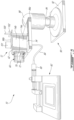
- the molding system 10 may further comprise a syringe 80 fluidly connected to the fitting 30 of the connector boot injection port 32 in the bottom wall 34 of the bottom half 14a of the outer shell 14.
- the system 10 may also comprise a syringe pump 82 operatively connected to the syringe 80 for injecting a resin mixture into the mold assembly 12 for molding the connector boot F over the connector C of the wire harness A.
- the syringe pump 82 may be adjusted to inject the resin mixture at a predetermined flow rate.
- a flexible tube 84 may be used to fluidly connect the syringe 80 to the fitting 30 on the mold assembly 12.
- the system 10 may further comprise a fixture 90 for holding the mold assembly 12 during the injection process.
- the fixture 90 comprises a base 92 including a table clamp, a column 94 projecting upwardly from the base 92 and any suitable mold retaining mechanisms, such as a pair of mold clamping plates 96a, 96b, articulately mounted to the column 94 via a ball joint 98 or the like.
- the exemplified retaining mechanism comprise a base plate 96a upon which the mold assembly 12 may be seated and a top plate 96b engageable on a pair of threaded rods 100 projecting upwardly from the base plate 96a.
- Wing nuts 102 are threadedly engageable with the threaded rods 100 for clamping the mold assembly 12 between the top plate 96b and the base plate 96a.
- a locking mechanism is operatively connected to the ball joint 98 for releasably holding the pair of mold clamping plates 96a, 96b in different positions relative to the column 94 and the base 92 during the injection process.
- the molding system 10 can be used to mold a replacement connector boot over the connector of an impaired wire harness or over the connector of a new wire harness.
- a damaged connector boot can be removed from the wire harness and a new connector boot can be molded over the connector of the impaired wire harness using the mold assembly 12 of the system 10.
- the system 10 can be used to mold a new boot directly over a damaged boot or over only a portion of the damaged boot (i.e., in some applications the damaged boot may not need to be removed).
- a method for molding a connector boot generally comprises: positioning the connector C of the wire harness A into the mold assembly 12; degassing a resin mixture (e.g., an epoxy resin mixture); injecting the de-aerated resin mixture into the mold cavity to gradually fill the mold cavity from bottom to the top; allowing the de-aerated resin mixture to harden to form the connector boot F around the connector C of the wire harness A; and demolding the connector boot F.
- a resin mixture e.g., an epoxy resin mixture
- the resin mixture may include a synthetic resin and a curing agent (i.e., a hardener) configured to chemically react with the synthetic resin so as to cure the resin from a flowable state to a solid state under isothermal conditions (i.e., without the addition of heat). In this way, there is no need to heat the mold to cause the resin to harden.
- the process may be conducted at substantially constant temperature.
- the synthetic resin and the curing agent are mixed and injected into the mold assembly 12 at room temperature. The injected resin mixture is then allowed to cure at room temperature inside the mold assembly 12.
- the resin mixture may be de-aerated in a vacuum chamber prior to injection into the mold assembly 12.
- the synthetic resin and the curing agent can be mixed together in a suitable receptacle (e.g. a bowl), degassed by appropriate means, then poured in the syringe 80 before injection into the mold assembly 12.
- a suitable receptacle e.g. a bowl
- degassed by appropriate means then poured in the syringe 80 before injection into the mold assembly 12.
- the de-aerated mixture is injected at a slow rate into the mold. Satisfactory results have been obtained by injecting the de-aerated resin mixture into the mold assembly 12 at a flow rate between 2ml/min and 4ml/min. It is understood that the injection flow rate may vary depending on the viscosity of the resin mixture.
- the syringe pump 82 can be calibrated to push on the plunger of the syringe 80 to inject the resin mixture at the desired rate. It is understood that other suitable resin injection arrangements could be used, the syringe pump 82 and associated syringe 80 being only one possible example.
- the mold assembly 12 can be tilted in different orientations to ensure proper filing of the mold cavity around the connector C of the wire harness A and, thus, avoid the formation of air cavities in the outer surface of the connector boot F.
- This can be conveniently achieved using an articulated fixture for holding the mold assembly 12 as for instance shown in Fig. 5 . Indeed, the operator can use the articulated fixture 90 to manually sequentially position the mold assembly 12 at different angles of inclination while the resin mixture is being injected.
- the operator knows that the mold cavity is completely full when some of the resin mixture starts to flow out from the overflow hole 40 in the top wall 42 of the outer shell 14 of the mold assembly 12.
- a small container 101 ( Fig. 5 ) can be connected to the overflow hole 40 to collect the excess resin flowing out from the mold assembly 12. Once the mold cavity is full, the syringe pump 82 can be shut down.
- the resin mixture is allowed to cure within the mold assembly 12. It is understood that the curing period may vary depending on the resin material used for molding the connector boot F. According to one example of an epoxy resin, the curing period within the mold assembly is between 18 and 24 hours.
- the mold assembly 12 can be opened to expose the molded connector boot F on the wire harness A.
- the demolded connector boot can then be submitted to a heat treatment to finalise the curing process and further improve the structural properties of the newly molded connector boot. This can be achieved by placing the wire harness in an oven and heating the wire harness at a temperature of about 100 Celsius for about 1 hour.
- the heat treatment process can be used as part of a quality control process to determine the presence of air bubbles in the resin material.
- connections are set forth between elements in the preceding description and in the drawings. It is noted that these connections are general and, unless specified otherwise, may be direct or indirect and that this specification is not intended to be limiting in this respect.
- a coupling between two or more entities may refer to a direct connection or an indirect connection.
- An indirect connection may incorporate one or more intervening entities.
- the term "connected” or “coupled to” may therefore include both direct coupling (in which two elements that are coupled to each other contact each other) and indirect coupling (in which at least one additional element is located between the two elements).
- the terms “comprises”, “comprising”, or any other variation thereof, are intended to cover a non-exclusive inclusion, such that a process, method, article, or apparatus that comprises a list of elements does not include only those elements but may include other elements not expressly listed or inherent to such process, method, article, or apparatus.
Landscapes
- Engineering & Computer Science (AREA)
- Mechanical Engineering (AREA)
- Manufacturing & Machinery (AREA)
- Injection Moulding Of Plastics Or The Like (AREA)
- Insulating Bodies (AREA)
Abstract
Description
- The application relates generally to wire harnesses and, more particularly, to a system and a method for molding a connector boot over a connector of a wire harness.
- Wiring harnesses, also know as cable harnesses or wiring harnesses, mounted to aircraft engines are subject to various sources of stress including: vibrations, thermal cycles to name a few. Over time, wire connector boots can crack and or be otherwise damaged necessitating repair or replacement. Connector boots can also be damaged during handling, including installation or removal.
- There is thus a need for continuous improvements in the manufacturing and replacement of wire harness connector boots.
- According to an aspect of the present invention, there is provided a molding system for molding a connector boot over a connector of a wire harness, the molding system comprising a mold assembly including an outer shell having a first outer shell part and a second outer shell part configured to be assembled together around the wire harness, the first and second outer shell parts defining an internal cavity bounded by a cavity surface; and interchangeable inner shells selectively removably positionable in the internal cavity of the outer shell, the interchangeable inner shells having an outer surface geometry that is complementary to a geometry of the cavity surface of the internal cavity of the outer shell, and different inner surface geometries corresponding to respective outer surface geometries of different connector boot models.
- According to another aspect of the present invention, there is provided a molding system for forming a molded component over a wire harness, the molding system comprising: an outer shell comprising a pair of metallic shell halves configured to be joined together to define a mold cavity around the wire harness, the mold cavity bounded by a cavity surface; interchangeable inner shells removably positionable in the mold cavity, each of the interchangeable inner shells comprising a pair of silicon shell halves, the interchangeable inner shells having an outer surface that is a positive of the cavity surface of the mold cavity of the outer shell, wherein a first inner shell of the interchangeable inner shells has a first inner surface geometry, wherein a second inner shell of the interchangeable inner shells has a second inner surface geometry, and wherein the first inner surface geometry is different from the second inner surface geometry.
- According to another aspect of the present invention, there is provided a molding system comprising an outer shell having a pair of shell halves configured to be joined together to define a mold cavity, the mold cavity bounded by a cavity surface; interchangeable inner shells removably positionable in the mold cavity, each of the interchangeable inner shells comprising a pair of shell halves, the interchangeable inner shells having an outer surface that is a positive of the cavity surface of the mold cavity of the outer shell, wherein a first inner shell of the interchangeable inner shells has a first inner surface geometry, wherein a second inner shell of the interchangeable inner shells has a second inner surface geometry, and wherein the first inner surface geometry is different from the second inner surface geometry.
- Optionally, and in accordance with any of the above, the molding system further comprises dummy connectors selectively positionable in the internal cavity of the outer shell for molding respective ones of the interchangeable inner shells, the dummy connectors each including: a main body having a connector boot portion receivable in the internal cavity, a cable portion and a connector portion, the connector portion and the cable portion configured to respectively extend through and seal a corresponding connector hole and a corresponding cable hole in the outer shell.
- Optionally, and in accordance with any of the above, the outer shell has an inner shell injection hole for injecting a first resin into the internal cavity of the outer shell around a selected one of the dummy connectors, and a connector boot injection port engaged with a fitting defining a connector boot injection hole for injecting a second resin in the internal cavity for molding the connector boot over the connector of the wire harness, and wherein each of the dummy connectors further has a connector boot plug extending from the main body to plug the connector boot injection hole during molding of a selected one of the interchangeable inner shells, the connector boot plug configured to form an injection hole in the selected one of the interchangeable inner shells.
- Optionally, and in accordance with any of the above, the outer shell has first and second overflow holes, and wherein each of the dummy connectors has an overflow hole plug extending from the main body to plug the first overflow hole of the outer shell during the molding of the selected one of the interchangeable inner shells, the overflow hole plug configured to form a third overflow hole in the selected one of the interchangeable inner shells.
- Optionally, and in accordance with any of the above, the outer shell has a connector hole and a cable hole for respectively accommodating a connector portion and a cable portion of the wire harness, the connector hole extending centrally through a cylindrical protrusion extending outwardly from the outer shell, and wherein the mold assembly further comprises: a cap rotatably engageable with the cylindrical protrusion, the cap rotatably connectable to the connector of the wire harness, and a dial to allow the cap to be rotated to a desired angular position, the dial including an angular scale and a pointer provided on respective ones of the outer shell and the cap.
- Optionally, and in accordance with any of the above, the angular scale comprises a circular clocking scale including angle markings from 0 degrees to 360 degrees provided on the outer shell around the cylindrical protrusion, the pointer provided in the form of a visual mark on an outer cylindrical surface of the cap.
- Optionally, and in accordance with any of the above, fasteners are provided for releasably securing the cap in the desired angular position on the cylindrical protrusion.
- Optionally, and in accordance with any of the above, the fasteners include set screws threadedly engaged in respective side holes defined in the cap for engagement with an outer surface of the cylindrical protrusion.
- Optionally, and in accordance with any of the above, the cap defines a drive socket for rotatably drivingly engaging the connector.
- Optionally, and in accordance with any of the above, the outer shell has a first cable hole, a second cable hole, and a connector hole, wherein the first cable hole and the connector hole are axially aligned along a straight line and disposed on opposed first and second parallel sides of the outer shell, the second cable hole disposed on a third side of the outer shell perpendicular to the first and second parallel sides, the second cable hole extending along an axis perpendicular to the straight line, and wherein the mold assembly further comprises a plug to plug a selected one of the first cable hole and the second cable hole.
- Optionally, and in accordance with any of the above, the molding system further comprises: a syringe fluidly connected to a or the fitting engaged with the connector boot injection port defined in a bottom surface of the outer shell of the mold assembly; a syringe pump operatively connected to the syringe; and a fixture comprising a retaining mechanism for holding the mold assembly, the retaining mechanism articulated to a column.
- Optionally, and in accordance with any of the above, the column extends upwardly from a base, the base including a table clamp configured for releasably securing the fixture to a table.
- Optionally, and in accordance with any of the above, the outer shell is a metal outer shell, and wherein the interchangeable inner shells are silicon inner shells, the metal outer shell and the silicon inner shells having registering injection holes (and/or ports) and overflow holes respectively defined in a bottom wall and an opposed upper wall thereof.
- Optionally, and in accordance with any of the above, the outer shell is a metal outer shell, the interchangeable inner shells are silicon inner shells, the metal outer shell has a or the connector boot injection port defined in a bottom wall thereof and in register with an injection hole defined in a bottom wall of the silicon inner shells, and the metal outer shell has an or the overflow hole defined in an upper wall thereof opposed to the bottom wall of the metal outer shell, the overflow hole of the metal outer shell in register with an overflow hole of the silicon inner shells defined in an upper wall opposed to the bottom wall of the silicon inner shells.
- Optionally, and in accordance with any of the above, the outer shell is a metal outer shell, the interchangeable inner shells are silicon inner shells the metal outer shell has a or the connector boot injection port defined in a bottom wall thereof and engaged with a fitting defining a or the connector boot injection hole, the connector boot injection hole in register with an injection hole defined in a bottom wall of the silicon inner shells, and the metal outer shell has an or the overflow hole defined in an upper wall thereof opposed to the bottom wall of the metal outer shell, the overflow hole of the metal outer shell in register with an overflow hole of the silicon inner shells defined in an upper wall opposed to the bottom wall of the silicon inner shells.
- Optionally, and in accordance with any of the above, the connector hole has an annular inner shoulder configured to form a seat for a corresponding outer shoulder on the connector of the wire harness, the seat facing outside of the internal cavity of the outer shell.
- Optionally, and in accordance with any of the above, the molding system further comprises a dummy connector, the dummy connector having a main body which has an outer geometry based on the design specifications of a connector of the wire harness, the dummy connector positionable in the mold cavity for molding the first inner shell of the interchangeable inner shells within the outer shell, the dummy connector including a first arm extending upwardly from the main body to produce an overflow hole in a top surface of the first inner shell, and a second arm extending downwardly from the main body to produce an injection hole in a bottom surface of the first inner shell, the injection hole and the overflow hole of the first inner shell respectively registering with a corresponding injection hole (and/or port) and a corresponding overflow hole in the outer shell.
- Optionally, and in accordance with any of the above, the dummy connector further a third arm projecting from the main body, the third arm configured to form a cable hole in the first inner shell, the cable hole configured for accommodating a cable portion of the wire harness.
- Optionally, and in accordance with any of the above, the outer shell has a connector hole configured for accommodating a connector of the wire harness, the connector hole extending through a cylindrical projection extending from an outer surface of the outer shell, and wherein the molding system further comprises a cap rotatably engaged on the cylindrical projection, the cap having a socket configured for driving engagement with the connector of the wire harness.
- Optionally, and in accordance with any of the above, a scale comprising angular markings is provided around the cylindrical projection on the outer surface of the outer shell, and wherein an indicator mark is provided on an outer cylindrical surface of the cap for alignment with a predetermined one of the angular markings on the outer shell.
- Optionally, and in accordance with any of the above, set screws are threadedly engaged with corresponding threaded holes extending through the cap for engagement with the cylindrical projection, the set screws operable for releasably securing the cap to the cylindrical projection.
- Reference is now made to the accompanying figures in which:
-
Fig. 1 is a schematic view of a wire harness comprising a connector boot molded over a connector, the connector of the wire harness configured for connection with a mating connector or receptacle of a component of an aircraft; -
Fig. 2 is a schematic isometric view of a molding system for molding connector boots over the connectors of wire harnesses, the system including a rigid outer shell and a set of interchangeable soft inner shells having different molding cavity geometries for molding different connector boot geometries; -
Fig. 3a is an isometric view of a dummy connector which can be used together with the outer shell of the molding system for producing an inner shell of the interchangeable inner shells of the system; -
Fig. 3b is a front cross-section view illustrating the dummy connector ofFig. 3a installed in the outer shell in preparation of the molding of an inner shell; -
Fig. 3c is a cross-section view taken alongline 3C-3C ofFig. 3b ; -
Fig. 4a is a perspective view of a wire harness installed in a bottom half of the mold assembly and illustrating a cap rotatably engageable with the connector of the wire harness to angularly adjust the orientation of the connector prior to the connector boot molding operation; -
Fig. 4b is an end cross-section view of the cap illustrating a square socket for rotatably drivingly engaging the connector; -
Fig. 4c is a cross-section view of the cap taken alongline 4C-4C ofFig. 4b ; -
Fig. 5 is a schematic isometric view of the molding system including a pump syringe, a syringe for injecting a resin mixture into the mold assembly over the connector of the wire harness, and an articulated fixture for holding the mold assembly during the injection process; and -
Fig. 6 is a flow chart of a method for molding a connector boot. -
Fig. 1 illustrates a wire harness A having a cable B including a bundle of wires connected to a connector C that is, in turn, configured for connection with a receptacle or mating connector D of a piece of equipment, such as an aircraft engine component E, to transfer electrical power, signals or data. A connector boot F is molded over the connector C of the wire harness A to provide strain relief and increase the attachment between the cable B and the connector C. The connector boot F is molded from a suitable resin material (e.g., epoxy), which once fully cured, is adapted to withstand the environmental conditions in which the wire harness A is to be installed and provide sufficient strength to effectively limit the bend radius of the wire harness A and prevent damages caused by kinking or snagging, impacts, vibrations, pressure and temperature to name a few. The mating connectors C and D may be provided with alignment/keying features to prevent mating in an incorrect orientation. For instance, a first one of the connectors (e.g., the wire harness connector C) may have one or more alignment pins or keys G for engagement with one or more corresponding keyways or notches H in the second one of the connectors (e.g., the aircraft component connector D). The connector C of the exemplified wire harness A is a right-angle connector. However, it is understood that the connector C could have other configurations. For instance, the connector of the wire harness could be a linear/straight connector. -
Fig. 2 illustrates parts of amolding system 10 suitable for molding a connector boot over the connector of a wire harness, such as the wire harness A exemplified inFig. 1 . Thesystem 10 generally comprises amold assembly 12 having an outer shell 14 and a set of interchangeableinner shells inner shells inner shells mold assembly 12 facilitate the change of connector boot form/geometry to be molded without changing the entire mold. That is different connector boot models/geometries can be molded over different wire harnesses using the same base mold. Such a mold assembly with interchangeable inner shells uses lesser tools, requires the handling of lesser parts and consequently generates economic savings. - The outer shell 14 of the
mold assembly 12 may be provided in the form of a rigid metal shell comprising a first outer shell part and a second outer shell part configured to be assembled together around the connector C of the wire harness A. According to some embodiments, the first and second outer shell parts respectively correspond to thebottom half 14a and thetop half 14b of the outer shell 14 (i.e., the outer shell 14 is divided into two halves adapted to be assembled along a median horizontal parting line). As can be appreciated fromFigs. 2 ,3b and 3c , the bottom andtop halves internal cavity 14c bounded by acavity surface 14d. The interchangeableinner shells cavity surface 14d of theinternal cavity 14c of the outer shell 14 (i.e., the outer surface of theinner shells cavity surface 14d of theinternal cavity 14c of the outer shell 14 have mutually complementing shapes). That is the common outer surface geometry of the interchangeableinner shells internal cavity 14c of the outer shell 14. In this way, eachinner shell cavity surface 14d of the outer shell 14. - Referring to
Figs. 3a to 3c , it can be appreciated that the interchangeableinner shells internal cavity 14c of the outer shell 14 for molding respective ones of the interchangeableinner shells Fig. 3a illustrates an example of such adummy connector 18. The exemplifieddummy connector 18 has a main body, which replicates the geometry/shape of the wire harness connector C over which the connector boot F is to be molded. That is the main body of thedummy connector 18 has the same outer geometrical features/outline as the connector C over which the connector boot F will be molded. Thedummy connector 18 can be created by any suitable means. For instance, thedummy connector 18 can be machined from a solid block of material, such as aluminum, based on measurements taken from an existing connector of a wire harness or from a CAD model generated from the design specifications of the original connector. The model created with CAD can be manufactured as a physical component using any suitable manufacturing processes, such as CNC machining, 3D printing, additive manufacturing or any other suitable manufacturing processes. - The
dummy connector 18 illustrated inFig. 3a is based on the design specifications of a right-angle connector. However, it is understood that the same principles could be applied to other angularly oriented connectors, including linear/straight connectors and 45 degrees connectors to name a few. The main body of the exemplifiedconnector 18 comprises aconnector boot portion 18a (i.e., the portion of the connector over which the connector boot is to be molded), acable portion 18b extending from a cable side of theconnector boot portion 18a and aconnector portion 18c extending from the connector contact side of theconnector boot portion 18a. Thecable portion 18b and theconnector portion 18c respectively correspond to a portion of the cable B extending from the right-angle connector C and to the connecting end portion of the connector C projecting out from the connector boot F on the wire harness A shown inFig. 1 . As can be appreciated inFigs. 3b and 3c , thecable portion 18b and theconnector portion 18c of thedummy connector 18 are respectively received in corresponding cable and connector holes 20 and 22 defined in the outer shell 14. For right angle connectors, thecable hole 20 and theconnector hole 22 are defined in two different orthogonal sides of the outer shell 14. According to some embodiments and as shown inFigs. 2 , and3c , the outer shell 14 can be provided with asecond cable hole 21 that is axially aligned with theconnector hole 22, thereby allowing the same outer shell 14 to be used for both linear and right-angle connector applications. As will be seen hereafter and as shown inFig. 3c , themold assembly 12 may further comprise acable hole plug 24 to plug the unused cable hole (i.e., the right-angle cable hole 20 or the straight cable hole 21) of the outer shell 14 during molding. According to the illustrated embodiment, the parting plane of the bottom andtop halves bottom half 14a of the outer shell 14 and a second haft of the cable and connector holes is defined in thetop half 14b of the outer shell 14). As shown inFigs. 3a-3c , O-rings 26 may be provided on thecable portion 18b and theconnector portion 18c of thedummy connector 18 to seal the cable and connector holes 20, 21 and 22 during molding of theinner shell cable portion 18b and theconnector portion 18c of thedummy connector 18 act as support arms for supporting theconnector boot portion 18a in theinternal cavity 14c of the outer shell 14. Thecable portion 18b and theconnector portion 18c can be integral to theconnector boot portion 18a or detachably mounted thereto. - Still referring to
Figs. 3a-3c , it can be appreciated that thedummy connector 18 further comprises a connector boot injection hole plug orfirst arm 18d extending downwardly from theconnector boot portion 18a of the main body of thedummy connector 18 to plug aninjection hole 28 defined in a fitting 30 threadedly engaged in a connectorboot injection port 32 defined in abottom wall 34 of thebottom half 14a of the outer shell 14. It can be appreciated that thearm 18d will form an injection hole in theinner shell 16a after the same has been molded over thedummy connector 18. As shown inFigs. 3a-3c , an O-ring 36 can be provided on thefirst arm 18d to enhance sealing of theinjection hole 28 of the fitting 30 from theinternal cavity 14c of the outer shell 14 during the molding of theinner shell 16a. Thefirst arm 18d can be threadedly mounted or otherwise detachably connected to theconnector boot portion 18a of the main body of thedummy connector 18. - Still referring to
Figs. 3a-3c , it can be seen that thedummy connector 18 further comprises an overflow hole plug orsecond arm 18e extending upwardly from theconnector boot portion 18a of the main body of thedummy connector 18 for plugging afirst overflow hole 40 defined in atop wall 42 of thetop half 14b of the outer shell 14. It can be appreciated that thissecond arm 18e will produce an overflow hole in theinner shell 16a after the same has been molded in the outer shell 14 over thedummy connector 18. An O-ring 44 may be provided on thesecond arm 18e to better seal theoverflow hole 40 during molding of theinner shell 16a. Like thefirst arm 18d, thesecond arm 18e can be threadedly mounted or otherwise detachably connected to theconnector boot portion 18a of the main body of thedummy connector 18. - In use, the
dummy connector 18 is positioned on thebottom half 14a of the outer shell 14 with thecable portion 18b and theconnector portion 18c respectively resting on the bottom half of thecable hole 20 and theconnector hole 22 and with thefirst arm 18d of thedummy connector 18 engaged in the connectorboot injection hole 28 of the injection fitting 30. Theplug 24 is also positioned in the bottom half of theunused cable hole 21. Then, thetop half 14b of the outer shell 14 is seated on top of thebottom half 14a of the outer shell 14 with thesecond arm 18e of thedummy connector 18 extending into theoverflow hole 40, and the twoouter shell halves connector boot portion 18a of thedummy connector 18 within the internal cavity of the outer shell 14. Dowel pins or the like may be provided at the mounting interface of the bottom andtop halves top halves dummy connector 18, a flowable resin, such as a silicon resin, is injected inside theinternal cavity 14c of the outer shell 14 via an inner shell injection hole 48 (Fig. 3b ) defined in thebottom wall 34 of thebottom half 14a of the outer shell 14. The resin gradually fills theinternal cavity 14c from bottom to top. According to some embodiments, the resin could be injected according to other orientations. A second overflow hole 50 (Fig. 3c ) is provided in thetop wall 42 of thetop half 14b of the outer shell 14 for excess resin to flow out of the outer shell 14 when theinternal cavity 14c starts to fill up. Thesecond overflow hole 50 also acts a vent for venting air from theinternal cavity 14c as the same is being filled up with the resin. After completing the injection process, the resin (e.g., the silicon resin) is allowed to cure to form theinner shell 16a around thedummy connector 18 and then the outer shell 14 is opened. The moldedinner shell 16a is retrieved from the outer shell 14 and cut in half, thereby providing bottom and topinner shell halves 16a', 16a" respectively positionable in a complementary fashion inside the bottom and topouter shell halves Fig. 2 , the so producedinner shell 16a has an injection hole/passage 52 and anoverflow hole 54 which are respectively aligned in registry with the corresponding connectorboot injection hole 28 and theoverflow hole 40 of the outer shell 14. In this way, the inner shell and the outer shell halves may be assembled together to form a mold assembly to mold a connector boot F over a given model of connector of virtually any wire harnesses. - From the foregoing, it can be appreciated that the use of a dummy connector for each connector shape to be molded allows to have the same repeatability for a same model of connector. Indeed, the use of a dummy connector instead of an originally made connector part to be repaired avoids replicating imperfections that might be present on the original part.
- As shown in
Figs. 4a-4c , it can be seen that themolding system 10 further comprises acap 60 having a clocking feature to angularly adjust the position of the keying/aligning features (such as the exemplified key G and keyway H of mating connectors C and D illustrated inFig. 1 ) of connectors of wiring harnesses prior to molding connector boots over the connectors. Thecap 60 is rotatably engageable over a cylindrical hollow protrusion orneck 62 projecting outwardly from the outer shell 14 centrally around theconnector hole 22 in which the connector C of the wire harness A is to be positioned for the molding of the connector boot F, as shown inFig. 4A . As shown inFigs. 4b-4c , thecap 60 has a polygonal socket 64 (a square socket in the illustrated example) defined in one end thereof for driving engagement with a mating polygonal flange 66 (a square flange in the illustrated example) of a connector/receptacle corresponding to the connector/receptacle D of the aircraft equipment E to which the connector C of the wire harness A is to be connected in a predetermined relative angular orientation. - To adjust the angular position of the wire harness connector C prior to the molding of the connector boot F, the connector/receptacle D with the
polygonal flange 66 is first connected to the mating connector C of the wire harness A and the wire harness A is positioned in the bottom half of the mold assembly 12 (i.e., thebottom half 14a of the outer shell 14 lined with thebottom half 16a' of the inner shell 16 as shown inFig. 4a ) with the mating portions of the connectors C, D accommodated inside the hollow cylindrical protrusion orneck 62 and with theflange 66 of the equipment connector/receptacle D lying outside of the neck/cylindrical protrusion 62 of the outer shell 14. Then, the top half of the mold assembly (thetop half 14b of the outer shell 14 lined with thetop half 16a" of the inner shell 16) is positioned over the bottom half of the mold assembly and the two mold halves are secured together. Thereafter, thecap 60 is engaged over thecylindrical projection 62 so as to engage thepolygonal flange 66 of the flanged connector D with the correspondingpolygonal socket 64 of thecap 60. Then, thecap 60 is rotated to rotate the connectors C, D to a predetermined angular position. A dial including anangular scale 70 and apointer 72 is provided on respective ones of the outer shell 14 and thecap 60 to precisely adjust the angular position of the connectors C, D. According to some embodiments, theangular scale 70 comprises a circular scale including angle markings from 0 degrees to 360 degrees on the outer shell 14 around thecylindrical protrusion 62. Thepointer 72 may be provided in the form of a visual mark or line on an outer circumferential surface of thecap 60. The system further comprises fasteners 76 (Fig. 4a ) for releasably securing thecap 60 in the desired angular position on thecylindrical protrusion 62 of the outer shell 14. Thefasteners 76 may be provided in the form of set screws threadedly engaged in respective side holes 78 (Figs. 4b and 4c ) defined in thecap 60 for engagement with the outer surface of thecylindrical protrusion 62. - Turning to
Fig. 5 , it can be seen that themolding system 10 may further comprise asyringe 80 fluidly connected to the fitting 30 of the connectorboot injection port 32 in thebottom wall 34 of thebottom half 14a of the outer shell 14. Thesystem 10 may also comprise asyringe pump 82 operatively connected to thesyringe 80 for injecting a resin mixture into themold assembly 12 for molding the connector boot F over the connector C of the wire harness A. Thesyringe pump 82 may be adjusted to inject the resin mixture at a predetermined flow rate. Aflexible tube 84 may be used to fluidly connect thesyringe 80 to the fitting 30 on themold assembly 12. - Still referring to
Fig. 5 , it can be seen that thesystem 10 may further comprise afixture 90 for holding themold assembly 12 during the injection process. According to some embodiments, thefixture 90 comprises a base 92 including a table clamp, acolumn 94 projecting upwardly from thebase 92 and any suitable mold retaining mechanisms, such as a pair ofmold clamping plates column 94 via a ball joint 98 or the like. The exemplified retaining mechanism comprise abase plate 96a upon which themold assembly 12 may be seated and atop plate 96b engageable on a pair of threadedrods 100 projecting upwardly from thebase plate 96a.Wing nuts 102 are threadedly engageable with the threadedrods 100 for clamping themold assembly 12 between thetop plate 96b and thebase plate 96a. A locking mechanism is operatively connected to the ball joint 98 for releasably holding the pair ofmold clamping plates column 94 and the base 92 during the injection process. - From the foregoing, it can be appreciated that the
molding system 10 can be used to mold a replacement connector boot over the connector of an impaired wire harness or over the connector of a new wire harness. For instance, a damaged connector boot can be removed from the wire harness and a new connector boot can be molded over the connector of the impaired wire harness using themold assembly 12 of thesystem 10. According to another possible application, thesystem 10 can be used to mold a new boot directly over a damaged boot or over only a portion of the damaged boot (i.e., in some applications the damaged boot may not need to be removed). - According to some embodiments and as illustrated by the flowchart of
Fig. 6 , a method for molding a connector boot generally comprises: positioning the connector C of the wire harness A into themold assembly 12; degassing a resin mixture (e.g., an epoxy resin mixture); injecting the de-aerated resin mixture into the mold cavity to gradually fill the mold cavity from bottom to the top; allowing the de-aerated resin mixture to harden to form the connector boot F around the connector C of the wire harness A; and demolding the connector boot F. - The resin mixture may include a synthetic resin and a curing agent (i.e., a hardener) configured to chemically react with the synthetic resin so as to cure the resin from a flowable state to a solid state under isothermal conditions (i.e., without the addition of heat). In this way, there is no need to heat the mold to cause the resin to harden. The process may be conducted at substantially constant temperature. According to some embodiments, the synthetic resin and the curing agent are mixed and injected into the
mold assembly 12 at room temperature. The injected resin mixture is then allowed to cure at room temperature inside themold assembly 12. - The resin mixture may be de-aerated in a vacuum chamber prior to injection into the
mold assembly 12. For instance, the synthetic resin and the curing agent can be mixed together in a suitable receptacle (e.g. a bowl), degassed by appropriate means, then poured in thesyringe 80 before injection into themold assembly 12. By so removing the air/gas from the resin mixture better material integrity can be obtained in the final product after the resin has hardened around the connector C of the wire harness A in themold assembly 12. It may prevent the presence of air bubbles in the connector boot material. This may lead to better structural properties and enhanced surface finish of the connector boot F. By injecting the resin material into the bottom of the mold and thus filing the mold from bottom to top, the probability of having air bubbles trapped in the connector boot material can be further reduced. - The de-aerated mixture is injected at a slow rate into the mold. Satisfactory results have been obtained by injecting the de-aerated resin mixture into the
mold assembly 12 at a flow rate between 2ml/min and 4ml/min. It is understood that the injection flow rate may vary depending on the viscosity of the resin mixture. Thesyringe pump 82 can be calibrated to push on the plunger of thesyringe 80 to inject the resin mixture at the desired rate. It is understood that other suitable resin injection arrangements could be used, thesyringe pump 82 and associatedsyringe 80 being only one possible example. - During the injection period, the
mold assembly 12 can be tilted in different orientations to ensure proper filing of the mold cavity around the connector C of the wire harness A and, thus, avoid the formation of air cavities in the outer surface of the connector boot F. This can be conveniently achieved using an articulated fixture for holding themold assembly 12 as for instance shown inFig. 5 . Indeed, the operator can use the articulatedfixture 90 to manually sequentially position themold assembly 12 at different angles of inclination while the resin mixture is being injected. - The operator knows that the mold cavity is completely full when some of the resin mixture starts to flow out from the
overflow hole 40 in thetop wall 42 of the outer shell 14 of themold assembly 12. A small container 101 (Fig. 5 ) can be connected to theoverflow hole 40 to collect the excess resin flowing out from themold assembly 12. Once the mold cavity is full, thesyringe pump 82 can be shut down. - After the injection step, the resin mixture is allowed to cure within the
mold assembly 12. It is understood that the curing period may vary depending on the resin material used for molding the connector boot F. According to one example of an epoxy resin, the curing period within the mold assembly is between 18 and 24 hours. After, this "isothermal" curing step, themold assembly 12 can be opened to expose the molded connector boot F on the wire harness A. The demolded connector boot can then be submitted to a heat treatment to finalise the curing process and further improve the structural properties of the newly molded connector boot. This can be achieved by placing the wire harness in an oven and heating the wire harness at a temperature of about 100 Celsius for about 1 hour. The heat treatment process can be used as part of a quality control process to determine the presence of air bubbles in the resin material. - It is noted that various connections are set forth between elements in the preceding description and in the drawings. It is noted that these connections are general and, unless specified otherwise, may be direct or indirect and that this specification is not intended to be limiting in this respect. A coupling between two or more entities may refer to a direct connection or an indirect connection. An indirect connection may incorporate one or more intervening entities. The term "connected" or "coupled to" may therefore include both direct coupling (in which two elements that are coupled to each other contact each other) and indirect coupling (in which at least one additional element is located between the two elements).
- It is further noted that various method or process steps for embodiments of the present invention are described in the description and drawings. The description may present the method and/or process steps as a particular sequence. However, to the extent that the method or process does not rely on the particular order of steps set forth herein, the method or process should not be limited to the particular sequence of steps described. As one of ordinary skill in the art would appreciate, other sequences of steps may be possible. Therefore, the particular order of the steps set forth in the description should not be construed as a limitation.
- As used herein, the terms "comprises", "comprising", or any other variation thereof, are intended to cover a non-exclusive inclusion, such that a process, method, article, or apparatus that comprises a list of elements does not include only those elements but may include other elements not expressly listed or inherent to such process, method, article, or apparatus.
- While various aspects of the present invention have been disclosed, it will be apparent to those of ordinary skill in the art that many more embodiments and implementations are possible within the scope of the present invention. For example, the present invention as described herein includes several aspects and embodiments that include particular features. Although these particular features may be described individually, it is within the scope of the present invention that some or all of these features may be combined with any one of the aspects and remain within the scope of the present invention. References to "various embodiments," "one embodiment," "an embodiment," "an example embodiment," etc., indicate that the embodiment described may include a particular feature, structure, or characteristic, but every embodiment may not necessarily include the particular feature, structure, or characteristic. Moreover, such phrases are not necessarily referring to the same embodiment. The use of the indefinite articles "a" and "an" as used herein with reference to a particular element is intended to encompass "one or more" such elements, and similarly the use of the definite article "the" in reference to a particular element is not intended to exclude the possibility that multiple of such elements may be present.
- The embodiments described in this document provide non-limiting examples of possible implementations of the present technology. Upon review of the present disclosure, a person of ordinary skill in the art will recognize that changes may be made to the embodiments described herein without departing from the scope of the present technology. For instance, it is understood that while the present technology as been described in the context of a connector boot of a wiring harness, the above described system and method could be used to provide different injection molded components over different articles (i.e., various aspects of the disclosed system and method could be applied to different products).
Claims (15)
- A molding system (10) for molding a connector boot (F) over a connector (C) of a wire harness (A), the molding system (10) comprising a mold assembly (12) including:an outer shell (14) having a first outer shell part (14a) and a second outer shell part (14b) configured to be assembled together around the wire harness (A), the first (14a) and second (14b) outer shell parts defining an internal cavity (14c) bounded by a cavity surface (14d); andinterchangeable inner shells (16a, 16b, 16c) selectively removably positionable in the internal cavity (14c) of the outer shell (14), the interchangeable inner shells (16a,16b,16c) having an outer surface geometry that is complementary to a geometry of the cavity surface (14d) of the internal cavity (14c) of the outer shell (14), and different inner surface geometries corresponding to respective outer surface geometries of different connector boot models.
- The molding system (10) as defined in claim 1, further comprising dummy connectors (18) selectively positionable in the internal cavity (14c) of the outer shell (14) for molding respective ones of the interchangeable inner shells (16a, 16b, 16c), the dummy connectors (18) each including:a main body having a connector boot portion (18a) receivable in the internal cavity (14c);a cable portion (18b); anda connector portion (18c), the connector portion (18c) and the cable portion (18b) configured to respectively extend through and seal a corresponding connector hole (22) and a corresponding cable hole (20) in the outer shell (14).
- The molding system (10) as defined in claim 2, wherein:the outer shell (14) has an inner shell injection hole (48) for injecting a first resin into the internal cavity (14c) of the outer shell (14) around a selected one of the dummy connectors (18), and a connector boot injection port (32) engaged with a fitting (30) defining a connector boot injection hole (28) for injecting a second resin in the internal cavity (14c) for molding the connector boot (F) over the connector (C) of the wire harness (A); andeach of the dummy connectors (18) further comprises a connector boot plug (18d) extending from the main body to plug the connector boot injection hole (28) during molding of a selected one of the interchangeable inner shells (16a, 16b, 16c), the connector boot plug (18d) configured to form an injection hole (52) in the selected one of the interchangeable inner shells (16a, 16b, 16c).
- The molding system (10) as defined in claim 2 or 3, wherein:the outer shell (14) has first (40) and second (50) overflow holes; andeach of the dummy connectors (18) has an overflow hole plug (18e) extending from the main body to plug the first overflow hole (40) of the outer shell (14) during the molding of the selected one of the interchangeable inner shells (16a,16b,16c), the overflow hole plug (18e) configured to form a third overflow hole in the selected one of the interchangeable inner shells (16a, 16b, 16c).
- The molding system (10) as defined in any preceding claim, wherein:the outer shell (14) has a or the connector hole (22) and a or the cable hole (20) for respectively accommodating a connector portion and a cable portion of the wire harness (A), the connector hole (22) extending centrally through a cylindrical protrusion (62) extending outwardly from the outer shell (14); andthe mold assembly (12) further comprises:a cap (60) rotatably engageable with the cylindrical protrusion (62), the cap (60) rotatably connectable to the connector (C) of the wire harness; anda dial to allow the cap (60) to be rotated to a desired angular position, the dial including an angular scale (70) and a pointer (72) provided on respective ones of the outer shell (14) and the cap (60).
- The molding system (10) as defined in claim 5, wherein the angular scale (70) comprises a circular clocking scale including angle markings from 0 degrees to 360 degrees provided on the outer shell (14) around the cylindrical protrusion (62), the pointer (72) provided in the form of a visual mark on an outer cylindrical surface of the cap (60).
- The molding system (10) as defined in claim 5 or 6, wherein fasteners (76) are provided for releasably securing the cap (60) in the desired angular position on the cylindrical protrusion (62).
- The molding system (10) as defined in claim 7, wherein the fasteners (76) include set screws threadedly engaged in respective side holes (78) defined in the cap (60) for engagement with an outer surface of the cylindrical protrusion (62).
- The molding system (10) as defined in any of claims 5 to 8, wherein the cap (60) defines a drive socket (64) for rotatably drivingly engaging the connector (C).
- The molding system (10) as defined in any of claims 5 to 9, wherein the connector hole (22) has an annular inner shoulder configured to form a seat for a corresponding outer shoulder on the connector (C) of the wire harness (A), the seat facing outside of the internal cavity (14c) of the outer shell (14).
- The molding system (10) as defined in any preceding claim, wherein:the outer shell (14) has a first cable hole (21), a second cable hole (20), and a or the connector hole (22), wherein the first cable hole (21) and the connector hole (22) are axially aligned along a straight line and disposed on opposed first and second parallel sides of the outer shell (14), the second cable hole (20) disposed on a third side of the outer shell (14) perpendicular to the first and second parallel sides, the second cable hole (20) extending along an axis perpendicular to the straight line; andthe mold assembly (12) further comprises a plug (24) to plug a selected one of the first cable hole (21) and the second cable hole (20).
- The molding system (10) as defined in any preceding claim, further comprising:a syringe (80) fluidly connected to a or the fitting (30) engaged with a or the connector boot injection port (32) defined in a bottom surface of the outer shell (14) of the mold assembly (12);a syringe pump (82) operatively connected to the syringe (80); anda fixture (90) comprising a retaining mechanism for holding the mold assembly (12), the retaining mechanism articulated to a column (94).
- The molding system (10) as defined in claim 12, wherein the column (94) extends upwardly from a base (92), the base (92) including a table clamp configured for releasably securing the fixture (90) to a table.
- The molding system (10) as defined in any preceding claim, wherein:the outer shell (14) is a metal outer shell;the interchangeable inner shells (16a,16b,16c) are silicon inner shells;the metal outer shell (14) has a or the connector boot injection port (32) defined in a bottom wall (34) thereof and in register with an injection hole (52) defined in a bottom wall of the silicon inner shells (16a, 16b, 16c); andthe metal outer shell (14) has an or the overflow hole (40) defined in an upper wall thereof opposed to the bottom wall (34) of the metal outer shell (14), the overflow hole (40) of the metal outer shell (14) in register with an overflow hole (54) of the silicon inner shells (16a,16b,16c) defined in an upper wall opposed to the bottom wall of the silicon inner shells (16a, 16b, 16c).
- The molding system (10) as defined in any preceding claim, wherein:the outer shell (14) is a metal outer shell;the interchangeable inner shells (16a,16b,16c) are silicon inner shells;the metal outer shell (14) has a or the connector boot injection port (32) defined in a bottom wall (34) thereof and engaged with a fitting (30) defining a or the connector boot injection hole (28), the connector boot injection hole (28) in register with an injection hole (52) defined in a bottom wall of the silicon inner shells (16a,16b,16c); andthe metal outer shell (14) has an or the overflow hole (40) defined in an upper wall thereof opposed to the bottom wall (34) of the metal outer shell (14), the overflow hole (40) of the metal outer shell (14) in register with an overflow hole (54) of the silicon inner shells (16a,16b,16c) defined in an upper wall opposed to the bottom wall of the silicon inner shells (16a, 16b, 16c).
Applications Claiming Priority (1)
| Application Number | Priority Date | Filing Date | Title |
|---|---|---|---|
| US18/524,099 US12679005B2 (en) | 2023-11-30 | 2023-11-30 | Wire harness connector boot molding |
Publications (2)
| Publication Number | Publication Date |
|---|---|
| EP4563316A2 true EP4563316A2 (en) | 2025-06-04 |
| EP4563316A3 EP4563316A3 (en) | 2025-10-01 |
Family
ID=93741789
Family Applications (1)
| Application Number | Title | Priority Date | Filing Date |
|---|---|---|---|
| EP24216305.3A Pending EP4563316A3 (en) | 2023-11-30 | 2024-11-28 | Wire harness connector boot molding |
Country Status (2)
| Country | Link |
|---|---|
| US (1) | US12679005B2 (en) |
| EP (1) | EP4563316A3 (en) |
Families Citing this family (1)
| Publication number | Priority date | Publication date | Assignee | Title |
|---|---|---|---|---|
| CN121670888A (en) * | 2026-02-03 | 2026-03-17 | 株洲一帆科技有限公司 | Epoxy adhesive tail-attached outer filling and sealing die for engine cable connector |
Family Cites Families (23)
| Publication number | Priority date | Publication date | Assignee | Title |
|---|---|---|---|---|
| US1949473A (en) | 1930-07-24 | 1934-03-06 | Us Tire Company Inc | Method and apparatus for forming rubber articles |
| IE892171A1 (en) * | 1989-07-06 | 1991-01-16 | Desbury Ltd | A mould for a cable connector |
| JP3269436B2 (en) | 1997-09-19 | 2002-03-25 | 株式会社村田製作所 | Manufacturing method of insert resin molded product |
| US6592356B1 (en) | 1999-05-05 | 2003-07-15 | Johnson & Johnson Vision Care, Inc. | Mold, molding system and molding machine for making ophthalmic devices |
| CA2313881C (en) | 2000-07-14 | 2006-10-17 | Tar Tsau | Universal blow mold assembly |
| JP2003331663A (en) | 2002-05-10 | 2003-11-21 | Sumitomo Wiring Syst Ltd | Wire harness manufacturing equipment |
| DE202005015875U1 (en) | 2005-10-07 | 2007-02-15 | S-Fasteners Gmbh | Holder arrangement for cables or similar with adjustable turn-stop positions |
| US7927525B2 (en) * | 2007-08-24 | 2011-04-19 | Lizotte Todd E | Vacuum isostatic micro molding of micro/nano structures and micro transfer metal films into PTFE and PTFE compounds |
| JP5208276B2 (en) | 2009-07-14 | 2013-06-12 | 三菱電機株式会社 | Vehicle state detection device and manufacturing method |
| US8573960B2 (en) | 2011-05-11 | 2013-11-05 | Ipar Mold S.A. De C.V. | Mold assembly with interchangeable insert for blow-molding |
| WO2013033726A1 (en) * | 2011-09-02 | 2013-03-07 | Quinonez Carlo Joseph | Universal hardware platform and toolset for operating and fabricating microfluidic devices |
| DE102011085032B4 (en) | 2011-10-21 | 2026-06-03 | Robert Bosch Gmbh | Device for holding a component to be encased in plastic and method for encasing a component |
| US11077586B2 (en) * | 2013-02-26 | 2021-08-03 | Cvg Management Corporation | Molded wire harness tool assembly |
| US9259865B2 (en) | 2013-03-17 | 2016-02-16 | The Boeing Company | Seal molding system and method |
| JP6409160B2 (en) | 2014-03-05 | 2018-10-24 | 矢崎総業株式会社 | Method of molding wire harness member |
| GB201718239D0 (en) | 2017-11-03 | 2017-12-20 | Rolls Royce Plc | A clocking and angle setting tool for a wire harness and method |
| DE102018210892B4 (en) | 2018-07-03 | 2025-08-07 | Bayerische Motoren Werke Aktiengesellschaft | Plug connection element for a motor vehicle and method for producing such a plug connection element |
| CN110524792B (en) | 2019-09-19 | 2021-06-22 | 安固集团有限公司 | Machining process of commutator |
| WO2021072542A1 (en) | 2019-10-16 | 2021-04-22 | Niigon Machines Ltd. | Injection molding machines and related methods for producing preforms |
| CN110649439A (en) | 2019-11-08 | 2020-01-03 | 东莞立德精密工业有限公司 | Method for manufacturing connector |
| PL3967888T3 (en) | 2020-09-14 | 2023-03-06 | Koninklijke Nedschroef Holding B.V. | Fixing device |
| CN116131200A (en) | 2021-11-12 | 2023-05-16 | 东莞忠佑电子有限公司 | Multi-wire harness waterproof structure, forming method and die |
| DE102023113207A1 (en) | 2023-05-19 | 2024-11-21 | Yazaki Systems Technologies Gmbh | Method for producing a mold and mold for producing a wire harness |
-
2023
- 2023-11-30 US US18/524,099 patent/US12679005B2/en active Active
-
2024
- 2024-11-28 EP EP24216305.3A patent/EP4563316A3/en active Pending
Also Published As
| Publication number | Publication date |
|---|---|
| US12679005B2 (en) | 2026-07-14 |
| US20250178242A1 (en) | 2025-06-05 |
| EP4563316A3 (en) | 2025-10-01 |
Similar Documents
| Publication | Publication Date | Title |
|---|---|---|
| EP4563317A2 (en) | Resin molding process | |
| US11179875B1 (en) | Modular blow mold system for blow molding a container | |
| US20250178242A1 (en) | Wire harness connector boot molding | |
| US9067345B2 (en) | Mold for manufacture of fiber composite parts and method of manufacture of fiber composite parts with such a mold | |
| EP0748684A1 (en) | Method of producing a strong, dimensionally stable object | |
| CN110497579B (en) | Investment casting method of pneumatic soft machine gripper | |
| CN114423578A (en) | Method, mold and device for forming composite material device | |
| US8250740B2 (en) | Method for making an inspection fixture, and mold assembly used in the method | |
| EP3915038A1 (en) | Casting modules and systems and methods for module-based casting | |
| CN109994907A (en) | A kind of production watertight connector socket mold and preparation method thereof | |
| GB2189183A (en) | Moulding plastic articles | |
| EP1091130A2 (en) | Manufacture of manifold modules or the like | |
| GB1567836A (en) | Moulded article reinforcing | |
| KR101119344B1 (en) | The core insert-method cooling-equipment of plastic injection molding | |
| CN111136224B (en) | Method for fixing sand core on metal mold | |
| EP1157810B1 (en) | Process for manufacturing structural parts made of composite material by resin transfer molding and equipment to carry out the process | |
| US12251858B2 (en) | Method and systems for composite molding | |
| EP0190897B1 (en) | Moulding methods | |
| JP7587925B2 (en) | Apparatus for demolding negative parts in thermoplastic injection moulds | |
| CN208068934U (en) | Composite material female connector molding die | |
| CN109278225B (en) | Die and blank manufacturing method | |
| CN216914919U (en) | Prefabricated part forming die | |
| US12330210B2 (en) | Method for producing flexible tooling for casting a ceramic core | |
| CN223146929U (en) | A multi-model positioning molding auxiliary tooling | |
| US3515366A (en) | Lost wax jewelry mold |
Legal Events
| Date | Code | Title | Description |
|---|---|---|---|
| PUAI | Public reference made under article 153(3) epc to a published international application that has entered the european phase |
Free format text: ORIGINAL CODE: 0009012 |
|
| STAA | Information on the status of an ep patent application or granted ep patent |
Free format text: STATUS: THE APPLICATION HAS BEEN PUBLISHED |
|
| AK | Designated contracting states |
Kind code of ref document: A2 Designated state(s): AL AT BE BG CH CY CZ DE DK EE ES FI FR GB GR HR HU IE IS IT LI LT LU LV MC ME MK MT NL NO PL PT RO RS SE SI SK SM TR |
|
| PUAL | Search report despatched |
Free format text: ORIGINAL CODE: 0009013 |
|
| AK | Designated contracting states |
Kind code of ref document: A3 Designated state(s): AL AT BE BG CH CY CZ DE DK EE ES FI FR GB GR HR HU IE IS IT LI LT LU LV MC ME MK MT NL NO PL PT RO RS SE SI SK SM TR |
|
| RIC1 | Information provided on ipc code assigned before grant |
Ipc: B29C 33/00 20060101AFI20250826BHEP Ipc: B29C 33/30 20060101ALI20250826BHEP Ipc: B29C 33/38 20060101ALI20250826BHEP Ipc: B29C 39/24 20060101ALI20250826BHEP Ipc: H01R 43/24 20060101ALI20250826BHEP Ipc: H01B 13/012 20060101ALI20250826BHEP Ipc: B29C 33/12 20060101ALI20250826BHEP Ipc: B29L 31/36 20060101ALN20250826BHEP |
|
| STAA | Information on the status of an ep patent application or granted ep patent |
Free format text: STATUS: REQUEST FOR EXAMINATION WAS MADE |
|
| 17P | Request for examination filed |
Effective date: 20260331 |