EP4563280A1 - Position detection device, air cylinder, workpiece unloader, and machine tool - Google Patents
Position detection device, air cylinder, workpiece unloader, and machine tool Download PDFInfo
- Publication number
- EP4563280A1 EP4563280A1 EP24214128.1A EP24214128A EP4563280A1 EP 4563280 A1 EP4563280 A1 EP 4563280A1 EP 24214128 A EP24214128 A EP 24214128A EP 4563280 A1 EP4563280 A1 EP 4563280A1
- Authority
- EP
- European Patent Office
- Prior art keywords
- turret
- bucket
- workpiece
- fluid filling
- air cylinder
- Prior art date
- Legal status (The legal status is an assumption and is not a legal conclusion. Google has not performed a legal analysis and makes no representation as to the accuracy of the status listed.)
- Pending
Links
Images




Classifications
-
- B—PERFORMING OPERATIONS; TRANSPORTING
- B23—MACHINE TOOLS; METAL-WORKING NOT OTHERWISE PROVIDED FOR
- B23Q—DETAILS, COMPONENTS, OR ACCESSORIES FOR MACHINE TOOLS, e.g. ARRANGEMENTS FOR COPYING OR CONTROLLING; MACHINE TOOLS IN GENERAL CHARACTERISED BY THE CONSTRUCTION OF PARTICULAR DETAILS OR COMPONENTS; COMBINATIONS OR ASSOCIATIONS OF METAL-WORKING MACHINES, NOT DIRECTED TO A PARTICULAR RESULT
- B23Q17/00—Arrangements for observing, indicating or measuring on machine tools
-
- B—PERFORMING OPERATIONS; TRANSPORTING
- B23—MACHINE TOOLS; METAL-WORKING NOT OTHERWISE PROVIDED FOR
- B23Q—DETAILS, COMPONENTS, OR ACCESSORIES FOR MACHINE TOOLS, e.g. ARRANGEMENTS FOR COPYING OR CONTROLLING; MACHINE TOOLS IN GENERAL CHARACTERISED BY THE CONSTRUCTION OF PARTICULAR DETAILS OR COMPONENTS; COMBINATIONS OR ASSOCIATIONS OF METAL-WORKING MACHINES, NOT DIRECTED TO A PARTICULAR RESULT
- B23Q7/00—Arrangements for handling work specially combined with or arranged in, or specially adapted for use in connection with, machine tools, e.g. for conveying, loading, positioning, discharging, sorting
- B23Q7/008—Catching devices
-
- B—PERFORMING OPERATIONS; TRANSPORTING
- B23—MACHINE TOOLS; METAL-WORKING NOT OTHERWISE PROVIDED FOR
- B23Q—DETAILS, COMPONENTS, OR ACCESSORIES FOR MACHINE TOOLS, e.g. ARRANGEMENTS FOR COPYING OR CONTROLLING; MACHINE TOOLS IN GENERAL CHARACTERISED BY THE CONSTRUCTION OF PARTICULAR DETAILS OR COMPONENTS; COMBINATIONS OR ASSOCIATIONS OF METAL-WORKING MACHINES, NOT DIRECTED TO A PARTICULAR RESULT
- B23Q7/00—Arrangements for handling work specially combined with or arranged in, or specially adapted for use in connection with, machine tools, e.g. for conveying, loading, positioning, discharging, sorting
- B23Q7/08—Arrangements for handling work specially combined with or arranged in, or specially adapted for use in connection with, machine tools, e.g. for conveying, loading, positioning, discharging, sorting by means of slides or chutes
-
- B—PERFORMING OPERATIONS; TRANSPORTING
- B23—MACHINE TOOLS; METAL-WORKING NOT OTHERWISE PROVIDED FOR
- B23Q—DETAILS, COMPONENTS, OR ACCESSORIES FOR MACHINE TOOLS, e.g. ARRANGEMENTS FOR COPYING OR CONTROLLING; MACHINE TOOLS IN GENERAL CHARACTERISED BY THE CONSTRUCTION OF PARTICULAR DETAILS OR COMPONENTS; COMBINATIONS OR ASSOCIATIONS OF METAL-WORKING MACHINES, NOT DIRECTED TO A PARTICULAR RESULT
- B23Q2220/00—Machine tool components
- B23Q2220/002—Tool turrets
-
- B—PERFORMING OPERATIONS; TRANSPORTING
- B23—MACHINE TOOLS; METAL-WORKING NOT OTHERWISE PROVIDED FOR
- B23Q—DETAILS, COMPONENTS, OR ACCESSORIES FOR MACHINE TOOLS, e.g. ARRANGEMENTS FOR COPYING OR CONTROLLING; MACHINE TOOLS IN GENERAL CHARACTERISED BY THE CONSTRUCTION OF PARTICULAR DETAILS OR COMPONENTS; COMBINATIONS OR ASSOCIATIONS OF METAL-WORKING MACHINES, NOT DIRECTED TO A PARTICULAR RESULT
- B23Q2707/00—Automatic supply or removal of metal workpieces
- B23Q2707/003—Automatic supply or removal of metal workpieces in a lathe
Definitions
- the present invention relates to a position detection device that detects a moving object being disposed at a predetermined position on a fixed object that is used for a machine tool, for example.
- JP 2016-144850A As described in JP 2016-144850A , the applicant has filed an application for a workpiece unloader in a machine tool that uses a turret to which various tools are attached, and that is capable of setting a tool to be used, to a predetermined angle.
- This workpiece unloader includes a bucket that receives a machined workpiece on a workpiece spindle, a support that is fixed to a tool attachment surface, and supports the bucket and allows the bucket to swing with respect to a swing axis parallel to a rotation shaft of the turret, and an air cylinder extending in a radial direction from a protruding portion on a leading end side of the turret such that a piston rod moves forward to and backward from an engagement hole formed in a bottom surface portion of the bucket.
- a portion of the air cylinder is disposed inside the protruding portion of the turret, and a position to which the piston rod has moved forward or backward is detected using a proximity sensor disposed inside the turret.
- JP 2016-144850A is an example of related art.
- the present invention has been made in light of the aforementioned problem, and an object of the present invention is to provide a position detection device that can detect movement of various actuators such as an air cylinder provided at a location where electrical wiring cannot be routed, and can be suitably used for a turret of a machine tool, for example.
- a position detection device is a position detection device that detects a state where a moving object that slides on a fixed object is disposed at a predetermined position, and includes: a fluid filling portion that is formed in the fixed object, and is open in a sliding surface of the fixed object, a pressure sensor that detects a pressure in the fluid filling portion, and a detection recessed portion that is formed in the moving object and aligns with an opening of the fluid filling portion when the moving object is disposed at the predetermined position.
- the pressure in the fluid filling portion is kept at a predetermined pressure when the moving object is at a position other than the predetermined position.
- the opening of the fluid filling portion aligns with the detection recessed portion, fluid flows from the fluid filling portion to the outside and the pressure in the fluid filling portion can be decreased. Therefore, the moving object being disposed at the predetermined position can be determined based on a decrease in the pressure that is detected by the pressure sensor.
- the pressure sensor even if the fixed object and the moving object are provided at locations where it is difficult to route electrical wiring, it suffices for the pressure sensor to be provided at a distant location where the pressure sensor is in communication with the fluid filling portion and the pressure thereof propagates to the pressure sensor, and thus even at a location where a proximity sensor cannot be used as with conventional cases, the position of the moving object can be detected.
- the position detection device may further include a determination device that determines that the moving object is disposed at the predetermined position when a pressure that is detected by the pressure sensor is lower than or equal to a threshold.
- an air cylinder may include: the position detection device according to the present invention, the fixed object that is a cylinder tube, and the moving object that is a piston rod.
- the fluid filling portion may be inner piping formed in a partition wall of the cylinder tube, and the detection recessed portion may be a ring-shaped groove formed in a side surface of the piston rod.
- the inner piping may further include: a leading end-side opening that is open in a sliding surface of the cylinder tube, and a base end-side opening that is open in an end portion of the cylinder tube, a rotary joint may be provided between the pressure sensor and the base end-side opening, and the pressure sensor may be configured to detect a pressure in the inner piping via the rotary joint.
- the position detection device does not need the sensor that requires electrical wiring to be provided near the moving object, and can detect the position of the moving object even at a location where the space is small or sealed as with the interior of the turret of the machine tool, for example.
- a machine tool 200, a workpiece unloader 100, an air cylinder 3, and a position detection device according to an embodiment of the present invention will be described below with reference to the drawings.
- the machine tool 200 is a multitasking lathe (multitasking machine), and includes a lathe body in which spindle headstocks are respectively disposed at two end portions, namely left and right end portions of a bed in front view, and a cutter holder is disposed between the left and right spindle headstocks, and is movable in the X axis direction and the Z axis direction, and a machine cover that surrounds the outer peripheral portion of the lathe body.
- a lathe body in which spindle headstocks are respectively disposed at two end portions, namely left and right end portions of a bed in front view
- a cutter holder is disposed between the left and right spindle headstocks, and is movable in the X axis direction and the Z axis direction
- a machine cover that surrounds the outer peripheral portion of the lathe body.
- the spindle headstocks have a structure for rotatably supporting a spindle to which a chuck for holding a workpiece W is attached. This spindle is driven and rotated by a drive motor.
- the cutter holder includes a cutter holder body movably supported by the bed, and a turret T mounted on the cutter holder body.
- This turret T has a structure in which a substantially octagonal prism-shaped turret head T2 having an outer peripheral portion on which a plurality of tools are mounted at a predetermined interval is supported such that rotary indexing can be performed by a rotary indexing table T1, and is configured such that a desired tool is rotationally indexed and positioned to a machining position (workpiece receiving position) vertically above the turret T, and the tool is clamped at the machining position.
- the tools are attached to a tool attachment surface TA of the turret head T2 in actuality, but, for simplification, only the workpiece unloader to be described later is illustrated in the drawings, and the tools are not illustrated.
- the machine tool 200 is configured to perform predetermined machining on the workpiece W held on the chuck of the spindle by applying one of the tools mounted on the turret T.
- This machine tool 200 includes a workpiece ejection device for ejecting the machined workpiece W to the outside.
- This ejection device includes: a bucket 1 that is installed on the turret T, and receives the machined workpiece W held on the chuck at the workpiece receiving position that is the machining position, and a housing box that rotates the workpiece W in the bucket 1 to a workpiece ejection position using rotation of the turret head T2 and houses the workpiece W via a shooter.
- the bucket 1 has a substantially V-shaped cross section having a receiving port and is supported by a support 2.
- This support 2 has a U-shape facing upward in front view, and one bottom plate portion of the support 2 is fixed to the tool attachment surface TA of the turret head T2 using a bolt.
- the other bottom plate portion of the support 2 is fixed to the air cylinder 3 that is provided on a later-described protruding portion T3 of the turret head T2 and protrudes in the radial direction.
- the bucket 1 is supported and allowed to swing by the support 2. That is to say, the bucket 1 is supported and allowed to swing with respect to a swing axis L2 parallel to a rotation axis L1 of the turret head T2.
- an engagement hole 11 is formed in a bottom surface portion of the bucket 1, and a leading end portion of a piston rod 32 that slides forward and backward on a cylinder tube 31, which is a fixed object of the air cylinder 3, is configured to move forward to or backward from the engagement hole 11.
- a locked state is entered where rotation with respect to the bucket swing axis L2 is restricted. Therefore, in this locked state, even when the turret head T2 rotates with respect to the rotation axis L1, a state where the opening direction of the bucket 1 faces the outer side in the radial direction of the turret head T2 is kept as shown in FIG. 3 .
- the bucket 1 in an unlocked state where the bucket 1 can freely swing with respect to the swing axis L2.
- a configuration is adopted in which the opening of the bucket 1 faces substantially upward while the turret head T2 is rotating within a predetermined angle range. That is to say, a configuration is adopted in which, within a rotation range of the turret 2 between the workpiece receiving position and the workpiece ejection position, the opening of the bucket 1 in the unlocked state always faces upward such that the workpiece does not fall naturally.
- the position detection device that detects the position of the leading end portion of the piston rod in the air cylinder 3 includes a first pressure sensor and a second pressure sensor provided outside the turret T, more specifically, near a CNC or the like, and the state of the piston rod is determined based on output of the pressure sensors. That is to say, no sensor or the like that requires electrical wiring is disposed in the turret T.
- the cylinder tube 31 is a tubular object having a substantially annular transverse cross-section, and a sliding surface on which the leading end portion of piston rod slides is formed on at least a portion of the inner side surface of the cylinder tube 31.
- a fluid filling portion 33 that allows compressed air or the like to circulate and is filled with compressed air is formed in a partition wall of the cylinder tube 31, for example, as a narrow cylindrical inner conduit.
- the leading end-side opening 34 when the leading end-side opening 34 is closed by the outer peripheral surface of the piston rod, the interior of the fluid filling portion 33 is pressurized.
- an annular groove is formed in a portion of the outer peripheral surface on the leading end side of the piston rod, as a detection recessed portion 35. In a state where the leading end-side opening 34 is aligned with the detection recessed portion 35, air partially escapes from the fluid filling portion 33 to the outside, and thus, in that case, the pressure in the fluid filling portion 33 falls below a predetermined pressure.
- the position detection device includes a pair of fluid filling portions 33, a first pressure sensor P1 and a second pressure sensor P2 that respectively measure pressures of the fluid filling portions 33, and a determination device J that determines the position of the leading end portion of the piston rod 32 based on output from the pressure sensors P1 and P2.
- the pressure sensors are in communication with the fluid filling portions 33, and are provided at remote locations to which the pressures of the fluid filling portions 33 can propagate, instead of being provided in or near the air cylinder 3 or the turret T.
- the pressure sensors P1 and P2 are disposed on the ceiling portion of the machine tool, for example, and the pressure sensors P1 and P2 are respectively connected to the fluid filling portions 33 by flow paths.
- the protruding portion T3 of the turret T is a rotating portion, and is a sealed space, where electrical wiring cannot be routed.
- a rotary joint RJ is provided in the protruding portion T3, and it is possible to transport fluid between the outside of the protruding portion T3 and the fluid filling portion of the air cylinder 3. That is to say, the pressure sensors P1 and P2 are configured to detect pressure in the fluid filling portions 33 via the rotary joint RJ. For this reason, there is no need to provide a sensor for position detection in the protruding portion T3, and there is no need for electrical wiring for outputting signals of the sensor, or the like.
- the position detection device is configured to be able to determine the position of the leading end portion of the piston rod 32 from among three positions.
- a state is detected where the piston rod 32 has retracted furthermost, bringing the bucket 1 in the unlocked state. That is to say, only the leading end-side opening 34 of the left fluid filling portion 33 in FIG.
- the pressure that is detected by the first pressure sensor P1 is lower than a predetermined pressure, which represents an OFF state, while the pressure that is detected by the second pressure sensor P2 is higher than or equal to the predetermined pressure, which represents an ON state.
- the determination device J determines that the bucket 1 is in the unlocked state as shown in FIG. 5 .
- FIG. 6 shows a state where the leading end portion of the piston rod 32 is inserted into the engagement hole 11 of the bucket 1.
- the leading end-side opening 34 of the left fluid filling portion 33 is closed by the outer surface of the piston rod 32, and thus the pressure that is measured by the first pressure sensor P1 is higher than the threshold pressure, which represents the ON state.
- the leading end-side opening 34 on the lower side of the right fluid filling portion 33 is aligned with the detection recessed portion 35, and thus the pressure decreases, and the pressure that is detected by the second pressure sensor P2 is lower than or equal to the threshold pressure, which represents the OFF state.
- the determination device J determines that the bucket 1 is in the locked state.
- the workpiece unloader 100 can detect the position of the leading end portion of the piston rod 32 on the air cylinder 3 based on the pressure of fluid. Therefore, it is possible to determine that the bucket 1 is reliably in the unlocked state during an operation of ejecting the machined workpiece W, and, while the workpiece W is machined, the bucket 1 can be reliably brought into the locked state so as not to interfere with machining by a tool attached to the turret T.
- the fluid filling portion is preferably filled with gas such as compressed air, but may be filled with liquid.
- the fluid filling portion may also be filled with a gas-liquid mixture.
- the air cylinder and the position detection device according to the present invention are not only applied to a workpiece unloader, but may also be applied to other usage in a machine tool.
- the shape of the detection recessed portion is not limited to an annular groove.
- the detection recessed portion may be a cavity such as a recess that causes a decrease in the pressure in the fluid filling portion when the position of the leading end-side opening is aligned with the position of the detection recessed portion.
- various embodiments may be modified and combined without departing from the spirit of the present invention.
Landscapes
- Engineering & Computer Science (AREA)
- Mechanical Engineering (AREA)
- Machine Tool Sensing Apparatuses (AREA)
- Feeding Of Workpieces (AREA)
- Turning (AREA)
- Actuator (AREA)
Abstract
Provided is a position detection device that can detect movement of various actuators such as an air cylinder provided at a location where electrical wiring cannot be routed, and can be suitably used for a turret of a machine tool, for example. The position detection device detects a state where a moving object 32 that slides on a fixed object 31 is disposed at a predetermined position, and includes: a fluid filling portion 33 that is formed in the fixed object 31, and is open in a sliding surface of the fixed object 31, a pressure sensor P1 that detects a pressure of the fluid filling portion 33, a detection recessed portion 35 that is formed in the moving object 32 and is aligned with an opening 34 of the fluid filling portion 33 when the moving object 32 is disposed at a predetermined position.
Description
- The present invention relates to a position detection device that detects a moving object being disposed at a predetermined position on a fixed object that is used for a machine tool, for example.
- As described in
JP 2016-144850A - When a leading end portion of the piston rod moves forward to and is inserted into the engagement hole, a locked state is entered in which swing of the bucket is restricted. Conversely, when the leading end portion of the piston rod moves backward and exits the engagement hole, the bucket enters an unlocked state where the bucket can freely swing. Movement of this workpiece unloader is controlled using the turret for applying a tool to a workpiece, and thus information on whether the bucket is in the locked state or the unlocked state needs to be obtained in each step.
- For this reason, a portion of the air cylinder is disposed inside the protruding portion of the turret, and a position to which the piston rod has moved forward or backward is detected using a proximity sensor disposed inside the turret.
- Incidentally, there are demands for a decrease in the size and advanced functionality of turrets, and thus it has been becoming difficult to dispose a portion of a piston rod, a proximity sensor, and the like inside the protruding portion of a turret. In addition, even if they can be disposed in the protruding portion of the turret, there are cases where the turret is sealed in order to protect an electronic device or the like from a coolant or the like, and it has also been becoming difficult to route electrical wiring for obtaining signals from the proximity sensor, in such an area.
-
JP 2016-144850A - The present invention has been made in light of the aforementioned problem, and an object of the present invention is to provide a position detection device that can detect movement of various actuators such as an air cylinder provided at a location where electrical wiring cannot be routed, and can be suitably used for a turret of a machine tool, for example.
- That is to say, a position detection device according to the present invention is a position detection device that detects a state where a moving object that slides on a fixed object is disposed at a predetermined position, and includes: a fluid filling portion that is formed in the fixed object, and is open in a sliding surface of the fixed object, a pressure sensor that detects a pressure in the fluid filling portion, and a detection recessed portion that is formed in the moving object and aligns with an opening of the fluid filling portion when the moving object is disposed at the predetermined position.
- With the above configuration, the pressure in the fluid filling portion is kept at a predetermined pressure when the moving object is at a position other than the predetermined position. On the other hand, when the moving object is disposed at the predetermined position and the opening of the fluid filling portion aligns with the detection recessed portion, fluid flows from the fluid filling portion to the outside and the pressure in the fluid filling portion can be decreased. Therefore, the moving object being disposed at the predetermined position can be determined based on a decrease in the pressure that is detected by the pressure sensor. In addition, even if the fixed object and the moving object are provided at locations where it is difficult to route electrical wiring, it suffices for the pressure sensor to be provided at a distant location where the pressure sensor is in communication with the fluid filling portion and the pressure thereof propagates to the pressure sensor, and thus even at a location where a proximity sensor cannot be used as with conventional cases, the position of the moving object can be detected.
- As a specific mode of position detection of the moving object that is based on a pressure, the position detection device may further include a determination device that determines that the moving object is disposed at the predetermined position when a pressure that is detected by the pressure sensor is lower than or equal to a threshold.
- As a specific example to which a principle for detecting the position of the moving object according to the present invention can be suitably applied, an air cylinder may include: the position detection device according to the present invention, the fixed object that is a cylinder tube, and the moving object that is a piston rod.
- In order to make it easy to cause a pressure change required for detecting a position of a leading end portion of the piston rod, the fluid filling portion may be inner piping formed in a partition wall of the cylinder tube, and the detection recessed portion may be a ring-shaped groove formed in a side surface of the piston rod.
- In order to make it possible for the pressure sensor provided at a remote location to detect the pressure in the fluid filling portion and to increase the degree of freedom of configuration even in a case where the air cylinder is disposed on a rotating segment and there is only a small and sealed space where it is difficult to route electrical wiring, the inner piping may further include: a leading end-side opening that is open in a sliding surface of the cylinder tube, and a base end-side opening that is open in an end portion of the cylinder tube, a rotary joint may be provided between the pressure sensor and the base end-side opening, and the pressure sensor may be configured to detect a pressure in the inner piping via the rotary joint.
- As a suitable application example of the air cylinder according to the present invention, a turret-rotating workpiece unloader that is provided on a turret of a machine tool may include: a bucket for receiving a workpiece held on a workpiece spindle, from a receiving port, a support that supports the bucket and allows the bucket to swing from a tool attachment surface of the turret in a rotation direction of the turret, and the air cylinder according to claim 3 provided between a turret head protruding in a rotation axis direction of the turret and the bucket, the workpiece unloader may be configured to be capable of switching between an unlocked state where the bucket is able to freely swing and a locked state where swing is restricted, based on forward or backward movement of the piston rod on the air cylinder, and the workpiece unloader may be used for a machine tool.
- As described above, the position detection device according to the present invention does not need the sensor that requires electrical wiring to be provided near the moving object, and can detect the position of the moving object even at a location where the space is small or sealed as with the interior of the turret of the machine tool, for example.
-
-
FIG. 1 is a schematic diagram of a workpiece unloader according to an embodiment of the present invention and a machine tool that includes the workpiece unloader. -
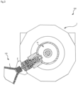
FIG. 2 is a schematic cross-sectional view taken along the line A-A inFIG. 1 . -
FIG. 3 is a schematic diagram showing an example of movement of the workpiece unloader when a bucket of the workpiece unloader is in a locked state. -
FIG. 4 is a schematic diagram showing an example of movement of the workpiece unloader in a case where the bucket of the workpiece unloader is in an unlocked state. -
FIG. 5 is a schematic diagram describing detection of the position of a leading end portion of a piston rod when the bucket of the workpiece unloader is in the unlocked state. -
FIG. 6 is a schematic diagram describing detection of the position of the leading end portion of the piston rod when the bucket of the workpiece unloader is in the locked state. -
FIG. 7 is a schematic diagram describing detection of the position of the leading end portion of the piston rod when the bucket of the workpiece unloader is in an idle stroke state. - A
machine tool 200, aworkpiece unloader 100, an air cylinder 3, and a position detection device according to an embodiment of the present invention will be described below with reference to the drawings. - In
FIGS. 1 and2 , themachine tool 200 is a multitasking lathe (multitasking machine), and includes a lathe body in which spindle headstocks are respectively disposed at two end portions, namely left and right end portions of a bed in front view, and a cutter holder is disposed between the left and right spindle headstocks, and is movable in the X axis direction and the Z axis direction, and a machine cover that surrounds the outer peripheral portion of the lathe body. - The spindle headstocks have a structure for rotatably supporting a spindle to which a chuck for holding a workpiece W is attached. This spindle is driven and rotated by a drive motor.
- The cutter holder includes a cutter holder body movably supported by the bed, and a turret T mounted on the cutter holder body. This turret T has a structure in which a substantially octagonal prism-shaped turret head T2 having an outer peripheral portion on which a plurality of tools are mounted at a predetermined interval is supported such that rotary indexing can be performed by a rotary indexing table T1, and is configured such that a desired tool is rotationally indexed and positioned to a machining position (workpiece receiving position) vertically above the turret T, and the tool is clamped at the machining position. Note that the tools are attached to a tool attachment surface TA of the turret head T2 in actuality, but, for simplification, only the workpiece unloader to be described later is illustrated in the drawings, and the tools are not illustrated.
- The
machine tool 200 is configured to perform predetermined machining on the workpiece W held on the chuck of the spindle by applying one of the tools mounted on the turret T. - This
machine tool 200 includes a workpiece ejection device for ejecting the machined workpiece W to the outside. This ejection device includes: abucket 1 that is installed on the turret T, and receives the machined workpiece W held on the chuck at the workpiece receiving position that is the machining position, and a housing box that rotates the workpiece W in thebucket 1 to a workpiece ejection position using rotation of the turret head T2 and houses the workpiece W via a shooter. - The
bucket 1 has a substantially V-shaped cross section having a receiving port and is supported by a support 2. This support 2 has a U-shape facing upward in front view, and one bottom plate portion of the support 2 is fixed to the tool attachment surface TA of the turret head T2 using a bolt. In addition, the other bottom plate portion of the support 2 is fixed to the air cylinder 3 that is provided on a later-described protruding portion T3 of the turret head T2 and protrudes in the radial direction. - The
bucket 1 is supported and allowed to swing by the support 2. That is to say, thebucket 1 is supported and allowed to swing with respect to a swing axis L2 parallel to a rotation axis L1 of the turret head T2. - Furthermore, an engagement hole 11 is formed in a bottom surface portion of the
bucket 1, and a leading end portion of a piston rod 32 that slides forward and backward on acylinder tube 31, which is a fixed object of the air cylinder 3, is configured to move forward to or backward from the engagement hole 11. In a state where the leading end portion of the piston rod 32 is inserted into the engagement hole 11 of thebucket 1, a locked state is entered where rotation with respect to the bucket swing axis L2 is restricted. Therefore, in this locked state, even when the turret head T2 rotates with respect to the rotation axis L1, a state where the opening direction of thebucket 1 faces the outer side in the radial direction of the turret head T2 is kept as shown inFIG. 3 . On the other hand, in a state where the piston rod 32 has moved backward and the leading end portion thereof is outside the engagement hole 11 of thebucket 1, thebucket 1 is in an unlocked state where thebucket 1 can freely swing with respect to the swing axis L2. In this state, as shown inFIG. 4 , a configuration is adopted in which the opening of thebucket 1 faces substantially upward while the turret head T2 is rotating within a predetermined angle range. That is to say, a configuration is adopted in which, within a rotation range of the turret 2 between the workpiece receiving position and the workpiece ejection position, the opening of thebucket 1 in the unlocked state always faces upward such that the workpiece does not fall naturally. - The position detection device that detects the position of the leading end portion of the piston rod in the air cylinder 3 includes a first pressure sensor and a second pressure sensor provided outside the turret T, more specifically, near a CNC or the like, and the state of the piston rod is determined based on output of the pressure sensors. That is to say, no sensor or the like that requires electrical wiring is disposed in the turret T.
- First, the position detection device that determines the position of the leading end portion of the piston rod will be described in detail with reference to
FIG. 5 . Thecylinder tube 31 is a tubular object having a substantially annular transverse cross-section, and a sliding surface on which the leading end portion of piston rod slides is formed on at least a portion of the inner side surface of thecylinder tube 31. In addition, afluid filling portion 33 that allows compressed air or the like to circulate and is filled with compressed air is formed in a partition wall of thecylinder tube 31, for example, as a narrow cylindrical inner conduit. Thefluid filling portion 33 is formed by forming a narrow hole along the axial direction of thecylinder tube 31, forming a narrow hole in the radial direction of the cylinder tube, in a region where the sliding surface is formed, and closing an opening on the outer peripheral surface side. That is to say, thefluid filling portion 33 is a space that includes a leading end-side opening 34 that is open in the sliding surface and a base end-side opening 36 that is open in an end surface portion of thecylinder tube 31 and is disposed on the opposite side to thebucket 1. A predetermined amount of compressed air flows into thefluid filling portion 33 from the base end-side opening 36. Here, when the leading end-side opening 34 is closed by the outer peripheral surface of the piston rod, the interior of thefluid filling portion 33 is pressurized. On the other hand, an annular groove is formed in a portion of the outer peripheral surface on the leading end side of the piston rod, as a detection recessedportion 35. In a state where the leading end-side opening 34 is aligned with the detection recessedportion 35, air partially escapes from thefluid filling portion 33 to the outside, and thus, in that case, the pressure in thefluid filling portion 33 falls below a predetermined pressure. - In the present embodiment, as shown in
FIG. 1 , the position detection device includes a pair offluid filling portions 33, a first pressure sensor P1 and a second pressure sensor P2 that respectively measure pressures of thefluid filling portions 33, and a determination device J that determines the position of the leading end portion of the piston rod 32 based on output from the pressure sensors P1 and P2. Here, the pressure sensors are in communication with thefluid filling portions 33, and are provided at remote locations to which the pressures of thefluid filling portions 33 can propagate, instead of being provided in or near the air cylinder 3 or the turret T. Specifically, the pressure sensors P1 and P2 are disposed on the ceiling portion of the machine tool, for example, and the pressure sensors P1 and P2 are respectively connected to thefluid filling portions 33 by flow paths. Here, as shown inFIG. 1 , the protruding portion T3 of the turret T is a rotating portion, and is a sealed space, where electrical wiring cannot be routed. On the other hand, a rotary joint RJ is provided in the protruding portion T3, and it is possible to transport fluid between the outside of the protruding portion T3 and the fluid filling portion of the air cylinder 3. That is to say, the pressure sensors P1 and P2 are configured to detect pressure in thefluid filling portions 33 via the rotary joint RJ. For this reason, there is no need to provide a sensor for position detection in the protruding portion T3, and there is no need for electrical wiring for outputting signals of the sensor, or the like. - Returning to
FIG. 5 again, there are three leading end-side openings 34, and are arranged along the axial direction of the air cylinder 3. In addition, two detection recessedportions 35 are provided in the piston rod. Based on combinations of the three leading end-side openings 34 and the two detection recessedportions 35 in a state of being fitted with each other, the position detection device according to the present embodiment is configured to be able to determine the position of the leading end portion of the piston rod 32 from among three positions. InFIG. 5 , a state is detected where the piston rod 32 has retracted furthermost, bringing thebucket 1 in the unlocked state. That is to say, only the leading end-side opening 34 of the leftfluid filling portion 33 inFIG. 5 and only the detection recessedportion 35 on the leading end side of the piston rod 32 are aligned with each other, and the two leading end-side openings 34 of the rightfluid filling portion 33 are closed by the side surface of the piston rod. Therefore, the pressure that is detected by the first pressure sensor P1 is lower than a predetermined pressure, which represents an OFF state, while the pressure that is detected by the second pressure sensor P2 is higher than or equal to the predetermined pressure, which represents an ON state. When the first pressure sensor P1 is in the OFF state and the second pressure sensor P2 is in the ON state, the determination device J determines that thebucket 1 is in the unlocked state as shown inFIG. 5 . -
FIG. 6 shows a state where the leading end portion of the piston rod 32 is inserted into the engagement hole 11 of thebucket 1. In this case, the leading end-side opening 34 of the leftfluid filling portion 33 is closed by the outer surface of the piston rod 32, and thus the pressure that is measured by the first pressure sensor P1 is higher than the threshold pressure, which represents the ON state. On the other hand, the leading end-side opening 34 on the lower side of the rightfluid filling portion 33 is aligned with the detection recessedportion 35, and thus the pressure decreases, and the pressure that is detected by the second pressure sensor P2 is lower than or equal to the threshold pressure, which represents the OFF state. In the case of such a combination of output of the pressure sensors P1 and P2, the determination device J determines that thebucket 1 is in the locked state. - Lastly, as shown in
FIG. 7 , when the piston rod 32 moves forward to the maximum extent in a state where thebucket 1 is swinging, and enters an idle stroke state where the leading end portion of the piston rod 32 is not inserted into the engagement hole 11, the leading end-side openings 34 of the left and rightfluid filling portions 33 are respectively aligned/fitted with the different detection recessedportions 35. In this case, both the first pressure sensor P1 and the second pressure sensor P2 are in the OFF state. In such a combination of output, the determination device J determines that an idle stroke abnormality has occurred, and causes a PLC or the like to emit an alert. - In this manner, even in a case where the air cylinder 3 is provided at a location of the turret T at which it is difficult to route electrical wiring, the
workpiece unloader 100 according to the present embodiment can detect the position of the leading end portion of the piston rod 32 on the air cylinder 3 based on the pressure of fluid. Therefore, it is possible to determine that thebucket 1 is reliably in the unlocked state during an operation of ejecting the machined workpiece W, and, while the workpiece W is machined, thebucket 1 can be reliably brought into the locked state so as not to interfere with machining by a tool attached to the turret T. - Other embodiments will be described. The fluid filling portion is preferably filled with gas such as compressed air, but may be filled with liquid. In addition, the fluid filling portion may also be filled with a gas-liquid mixture. The air cylinder and the position detection device according to the present invention are not only applied to a workpiece unloader, but may also be applied to other usage in a machine tool. The shape of the detection recessed portion is not limited to an annular groove. In short, the detection recessed portion may be a cavity such as a recess that causes a decrease in the pressure in the fluid filling portion when the position of the leading end-side opening is aligned with the position of the detection recessed portion. Besides, various embodiments may be modified and combined without departing from the spirit of the present invention.
-
- 200
- Machine tool
- 100
- Workpiece unloader
- 1
- Bucket
- 2
- Support
- 3
- Air cylinder
- 31
- Cylinder tube (fixed object)
- 32
- Piston rod (moving object)
- 33
- Fluid filling portion
- 34
- Leading end-side opening
- 35
- Detection recessed portion
Claims (7)
- A position detection device that detects a state where a moving object that slides on a fixed object is disposed at a predetermined position, the device comprising:a fluid filling portion that is formed in the fixed object, and is open in a sliding surface of the fixed object;a pressure sensor that detects a pressure in the fluid filling portion; anda detection recessed portion that is formed in the moving object and aligns with an opening of the fluid filling portion when the moving object is disposed at the predetermined position.
- The position detection device according to claim 1, further comprising
a determination device that determines that the moving object is disposed at the predetermined position when a pressure that is detected by the pressure sensor is lower than or equal to a threshold. - An air cylinder comprising:the position detection device according to claim 1 or 2;the fixed object that is a cylinder tube; andthe moving object that is a piston rod.
- The air cylinder according to claim 3,wherein the fluid filling portion is inner piping formed in a partition wall of the cylinder tube, andthe detection recessed portion is a ring-shaped groove formed in a side surface of the piston rod.
- The air cylinder according to claim 3,wherein the inner piping further includes: a leading end-side opening that is open in a sliding surface of the cylinder tube, and a base end-side opening that is open in an end portion of the cylinder tube,a rotary joint is provided between the pressure sensor and the base end-side opening, andthe pressure sensor is configured to detect a pressure in the inner piping via the rotary joint.
- A turret-rotating workpiece unloader that is provided on a turret of a machine tool, the turret-rotating workpiece unloader comprising:a bucket for receiving a workpiece held on a workpiece spindle, from a receiving port;a support that supports the bucket and allows the bucket to swing from a tool attachment surface of the turret in a rotation direction of the turret; andthe air cylinder according to claim 3 provided between a turret head protruding in a rotation axis direction of the turret and the bucket,wherein the workpiece unloader is configured to be capable of switching between an unlocked state where the bucket is able to freely swing and a locked state where swing is restricted, based on forward or backward movement of the piston rod on the air cylinder.
- A machine tool that includes the workpiece unloader according to claim 6.
Applications Claiming Priority (1)
| Application Number | Priority Date | Filing Date | Title |
|---|---|---|---|
| JP2023203115A JP7750923B2 (en) | 2023-11-30 | 2023-11-30 | Position detection device, air cylinder, workpiece unloader, and machine tool |
Publications (1)
| Publication Number | Publication Date |
|---|---|
| EP4563280A1 true EP4563280A1 (en) | 2025-06-04 |
Family
ID=94210502
Family Applications (1)
| Application Number | Title | Priority Date | Filing Date |
|---|---|---|---|
| EP24214128.1A Pending EP4563280A1 (en) | 2023-11-30 | 2024-11-20 | Position detection device, air cylinder, workpiece unloader, and machine tool |
Country Status (2)
| Country | Link |
|---|---|
| EP (1) | EP4563280A1 (en) |
| JP (1) | JP7750923B2 (en) |
Citations (2)
| Publication number | Priority date | Publication date | Assignee | Title |
|---|---|---|---|---|
| JP2016144850A (en) | 2015-02-09 | 2016-08-12 | Dmg森精機株式会社 | Work-piece unloading device in machine tool |
| JP2020131417A (en) * | 2019-02-26 | 2020-08-31 | トヨタ自動車株式会社 | Clamp device |
Family Cites Families (8)
| Publication number | Priority date | Publication date | Assignee | Title |
|---|---|---|---|---|
| US4426177A (en) * | 1981-08-31 | 1984-01-17 | Invo Spline, Inc. | Automatic fault detection system for a machine tool |
| JPH0215839U (en) * | 1988-07-19 | 1990-01-31 | ||
| JPH0435837A (en) * | 1990-05-29 | 1992-02-06 | Suzuki Motor Corp | Work carrying-out device for gear inspecting machine |
| JPH0740199A (en) * | 1993-02-04 | 1995-02-10 | Toyota Motor Corp | Work attachment confirmation device |
| JP2003136399A (en) * | 2001-11-01 | 2003-05-14 | Nippei Toyama Corp | Work holding device for machine tools |
| JP2005040903A (en) * | 2003-07-23 | 2005-02-17 | Okuma Corp | Work machine external dispensing device |
| JP6670528B2 (en) * | 2016-01-14 | 2020-03-25 | 株式会社コスメック | Positioning device with breakage detection function |
| JP6681219B2 (en) * | 2016-03-02 | 2020-04-15 | 株式会社コスメック | Positioning device with motion detection function |
-
2023
- 2023-11-30 JP JP2023203115A patent/JP7750923B2/en active Active
-
2024
- 2024-11-20 EP EP24214128.1A patent/EP4563280A1/en active Pending
Patent Citations (2)
| Publication number | Priority date | Publication date | Assignee | Title |
|---|---|---|---|---|
| JP2016144850A (en) | 2015-02-09 | 2016-08-12 | Dmg森精機株式会社 | Work-piece unloading device in machine tool |
| JP2020131417A (en) * | 2019-02-26 | 2020-08-31 | トヨタ自動車株式会社 | Clamp device |
Also Published As
| Publication number | Publication date |
|---|---|
| JP7750923B2 (en) | 2025-10-07 |
| JP2025088423A (en) | 2025-06-11 |
Similar Documents
| Publication | Publication Date | Title |
|---|---|---|
| US10369673B2 (en) | Spindle device for a program-controlled machine tool | |
| US5214829A (en) | Carriage structure of NC lathe | |
| US8186249B2 (en) | Three point turning machine | |
| US4579487A (en) | Tool adapter | |
| CN102802847A (en) | Main spindle apparatus for machine tool | |
| US4944643A (en) | Torque thrust and surface sensing device | |
| JP7463496B2 (en) | Tool blade adjustment head, its operation method, and tool blade wear compensation | |
| EP2335866B1 (en) | 5-face machining angle tool holder | |
| ES3023161T3 (en) | Tool exchange system for plotter | |
| US6128985A (en) | Machine tool | |
| US20240416426A1 (en) | Tool Rest and Machine Tool | |
| WO2024070395A1 (en) | Member replacement device | |
| JP7750923B2 (en) | Position detection device, air cylinder, workpiece unloader, and machine tool | |
| US5820537A (en) | Tool changing device for machine tool | |
| EP2342046B1 (en) | Method for monitoring the contact of a tool holder | |
| US12005544B2 (en) | Measuring method and measuring system for measuring drilled holes, and precision machine tool with a measuring system | |
| JP2013212550A (en) | Clamping device of machine tool | |
| CN212824111U (en) | Cylinder clamping head seat | |
| JP2000218471A (en) | Method of detecting workpiece in machine tool, detecting head and turret lathe | |
| JP6970322B1 (en) | Turret, clamp state detection method, and clamp state detection program | |
| JP7527484B2 (en) | Processing Machinery | |
| US11084135B2 (en) | Clamping mechanism and machining center having the same | |
| JP2023078560A (en) | Boring bar | |
| JP6768159B2 (en) | Work posture discrimination mechanism of robot chuck | |
| CN223588930U (en) | A long-stroke vertical automatic tool changer machining center |
Legal Events
| Date | Code | Title | Description |
|---|---|---|---|
| PUAI | Public reference made under article 153(3) epc to a published international application that has entered the european phase |
Free format text: ORIGINAL CODE: 0009012 |
|
| STAA | Information on the status of an ep patent application or granted ep patent |
Free format text: STATUS: REQUEST FOR EXAMINATION WAS MADE |
|
| 17P | Request for examination filed |
Effective date: 20250411 |
|
| AK | Designated contracting states |
Kind code of ref document: A1 Designated state(s): AL AT BE BG CH CY CZ DE DK EE ES FI FR GB GR HR HU IE IS IT LI LT LU LV MC ME MK MT NL NO PL PT RO RS SE SI SK SM TR |