EP4563240A1 - Small spray pump head - Google Patents
Small spray pump head Download PDFInfo
- Publication number
- EP4563240A1 EP4563240A1 EP24175811.9A EP24175811A EP4563240A1 EP 4563240 A1 EP4563240 A1 EP 4563240A1 EP 24175811 A EP24175811 A EP 24175811A EP 4563240 A1 EP4563240 A1 EP 4563240A1
- Authority
- EP
- European Patent Office
- Prior art keywords
- groove
- inner plug
- mouth
- ring
- spring
- Prior art date
- Legal status (The legal status is an assumption and is not a legal conclusion. Google has not performed a legal analysis and makes no representation as to the accuracy of the status listed.)
- Granted
Links
Images


Classifications
-
- B—PERFORMING OPERATIONS; TRANSPORTING
- B65—CONVEYING; PACKING; STORING; HANDLING THIN OR FILAMENTARY MATERIAL
- B65D—CONTAINERS FOR STORAGE OR TRANSPORT OF ARTICLES OR MATERIALS, e.g. BAGS, BARRELS, BOTTLES, BOXES, CANS, CARTONS, CRATES, DRUMS, JARS, TANKS, HOPPERS, FORWARDING CONTAINERS; ACCESSORIES, CLOSURES, OR FITTINGS THEREFOR; PACKAGING ELEMENTS; PACKAGES
- B65D47/00—Closures with filling and discharging, or with discharging, devices
- B65D47/04—Closures with discharging devices other than pumps
- B65D47/20—Closures with discharging devices other than pumps comprising hand-operated members for controlling discharge
- B65D47/24—Closures with discharging devices other than pumps comprising hand-operated members for controlling discharge with poppet valves or lift valves, i.e. valves opening or closing a passageway by a relative motion substantially perpendicular to the plane of the seat
- B65D47/245—Closures with discharging devices other than pumps comprising hand-operated members for controlling discharge with poppet valves or lift valves, i.e. valves opening or closing a passageway by a relative motion substantially perpendicular to the plane of the seat the valve being opened or closed by actuating a stopper-type element
- B65D47/247—Closures with discharging devices other than pumps comprising hand-operated members for controlling discharge with poppet valves or lift valves, i.e. valves opening or closing a passageway by a relative motion substantially perpendicular to the plane of the seat the valve being opened or closed by actuating a stopper-type element moving linearly, i.e. without rotational motion
-
- B—PERFORMING OPERATIONS; TRANSPORTING
- B05—SPRAYING OR ATOMISING IN GENERAL; APPLYING FLUENT MATERIALS TO SURFACES, IN GENERAL
- B05B—SPRAYING APPARATUS; ATOMISING APPARATUS; NOZZLES
- B05B11/00—Single-unit hand-held apparatus in which flow of contents is produced by the muscular force of the operator at the moment of use
- B05B11/01—Single-unit hand-held apparatus in which flow of contents is produced by the muscular force of the operator at the moment of use characterised by the means producing the flow
- B05B11/10—Pump arrangements for transferring the contents from the container to a pump chamber by a sucking effect and forcing the contents out through the dispensing nozzle
- B05B11/1028—Pumps having a pumping chamber with a deformable wall
-
- B—PERFORMING OPERATIONS; TRANSPORTING
- B05—SPRAYING OR ATOMISING IN GENERAL; APPLYING FLUENT MATERIALS TO SURFACES, IN GENERAL
- B05B—SPRAYING APPARATUS; ATOMISING APPARATUS; NOZZLES
- B05B11/00—Single-unit hand-held apparatus in which flow of contents is produced by the muscular force of the operator at the moment of use
- B05B11/01—Single-unit hand-held apparatus in which flow of contents is produced by the muscular force of the operator at the moment of use characterised by the means producing the flow
- B05B11/10—Pump arrangements for transferring the contents from the container to a pump chamber by a sucking effect and forcing the contents out through the dispensing nozzle
- B05B11/1042—Components or details
- B05B11/1073—Springs
- B05B11/1074—Springs located outside pump chambers
-
- A—HUMAN NECESSITIES
- A45—HAND OR TRAVELLING ARTICLES
- A45D—HAIRDRESSING OR SHAVING EQUIPMENT; EQUIPMENT FOR COSMETICS OR COSMETIC TREATMENTS, e.g. FOR MANICURING OR PEDICURING
- A45D34/00—Containers or accessories specially adapted for handling liquid toiletry or cosmetic substances, e.g. perfumes
-
- B—PERFORMING OPERATIONS; TRANSPORTING
- B05—SPRAYING OR ATOMISING IN GENERAL; APPLYING FLUENT MATERIALS TO SURFACES, IN GENERAL
- B05B—SPRAYING APPARATUS; ATOMISING APPARATUS; NOZZLES
- B05B11/00—Single-unit hand-held apparatus in which flow of contents is produced by the muscular force of the operator at the moment of use
- B05B11/01—Single-unit hand-held apparatus in which flow of contents is produced by the muscular force of the operator at the moment of use characterised by the means producing the flow
- B05B11/10—Pump arrangements for transferring the contents from the container to a pump chamber by a sucking effect and forcing the contents out through the dispensing nozzle
- B05B11/1001—Piston pumps
-
- B—PERFORMING OPERATIONS; TRANSPORTING
- B05—SPRAYING OR ATOMISING IN GENERAL; APPLYING FLUENT MATERIALS TO SURFACES, IN GENERAL
- B05B—SPRAYING APPARATUS; ATOMISING APPARATUS; NOZZLES
- B05B11/00—Single-unit hand-held apparatus in which flow of contents is produced by the muscular force of the operator at the moment of use
- B05B11/01—Single-unit hand-held apparatus in which flow of contents is produced by the muscular force of the operator at the moment of use characterised by the means producing the flow
- B05B11/10—Pump arrangements for transferring the contents from the container to a pump chamber by a sucking effect and forcing the contents out through the dispensing nozzle
- B05B11/1042—Components or details
- B05B11/1043—Sealing or attachment arrangements between pump and container
- B05B11/1046—Sealing or attachment arrangements between pump and container the pump chamber being arranged substantially coaxially to the neck of the container
- B05B11/1047—Sealing or attachment arrangements between pump and container the pump chamber being arranged substantially coaxially to the neck of the container the pump being preassembled as an independent unit before being mounted on the container
-
- A—HUMAN NECESSITIES
- A45—HAND OR TRAVELLING ARTICLES
- A45D—HAIRDRESSING OR SHAVING EQUIPMENT; EQUIPMENT FOR COSMETICS OR COSMETIC TREATMENTS, e.g. FOR MANICURING OR PEDICURING
- A45D34/00—Containers or accessories specially adapted for handling liquid toiletry or cosmetic substances, e.g. perfumes
- A45D2034/002—Accessories
Definitions
- the present invention relates to a spray nozzle for mini sprayers and in particular, a small spray pump head.
- the aim of the present invention is to provide a small spray pump head to the field, so that it is designed to solve the existing similar products production and assembly is more inconvenient, production costs are higher, especially when the spray effect is poor, it is likely to incur back suction which is considered a technical challenge.
- the purpose is achieved by the following technical solutions.
- a small spray pump head comprising of a head cap, an inner plug, a spring, and a large ring
- the head cap has a spray hole on one side, while the inner plug is placed in the liquid outlet hole of the large ring; wherein the liquid outlet hole of the large ring is a plunger hole, with the plunger hole on top of the large ring communicating with the suction tube hole on the bottom.
- the plunger hole of the large ring has a bush groove and a spring groove sequentially disposed around its outer diameter, with the spring placed in the spring groove; the inner plug is T-shaped, with the lower sleeve level having an upper spring plug.
- the lower bush of the inner plug also has a central column and a wall guide groove in the lower bush.
- the said wall guide groove is connected to the thru-hole on top of the inner hole; the central column of the inner plug is inserted into the plunger hole of the large ring, while the lower bush of the inner plug is inserted into the bush groove of the large ring.
- One end of the spring is placed against the bottom inside of the spring groove of the large ring, with the other end placed against the lower ring groove on the bottom of the upper spring plug of the inner plug; the outer diameter of the lower ring groove of the inner plug is an elastic sleeve, a spring cavity is formed as the groove mouth at the lower ring groove of the inner plug is placed against the groove mouth outside of the spring groove of the large spring, the spring is then sealed within this cavity.
- a top cover groove is disposed on top of the upper spring plug of the inner plug, and an upwardly protruding cover piece is disposed in the top cover groove of the inner plug.
- the thru-hole of the inner plug is located within the said cover piece: Upon pressing the head cap, the inner plug moves downward to cause deformation of the spring, cover piece, and the elastic sleeve of the inner plug, the thru-hole of the inner plug is sealed by the cover piece, allowing liquid to be sprayed through the spray hole of the head cap via the wall guide groove of the inner plug, and by means of atomization resulting from the deformation of cover piece and the elastic sleeve of the inner plug.
- the spring is a metal or plastic spring.
- the mouth edge of the said cover piece is provided with a downwardly protruding sealing skirt, or the outer radial direction of the sealing skirt is upwardly upturned to fit into the beveled edge of the inner diameter of the cap groove at the top of the inner plug, and the sealing skirt of the cover piece is placed and sealed against the inner thru-hole in the cap groove at the top of the inner plug.
- Two types of structural embodiments of the cover piece are described above, each corresponding to a specific locating cylindrical pin or locating ring design, thereby enhancing its stability against deformation.
- the said cover piece is provided with a raised locating cylindrical pin or locating ring bar in the middle of the top of said cover piece, the locating cylindrical pin or the locating ring bar is inserted into the corresponding groove at the top of the head cap.
- a raised step bar is provided at the chamfer of the outer diameter of the plunger hole at the bottom of the bush groove of the said large ring, the bottom part of the lower bush to which the step bar corresponds to the inner plug is provided with a lower bush groove.
- the said head cap is provided with an inwardly protruding cap mouth bar, the outer diameter of the cap mouth bar of the large ring in the head cap above the cap mouth bar is provided with a raised groove ring, the groove mouth ring of the large ring is inserted into the cap mouth bar of the head cap by interference fit, the lower outer diameter of the cap mouth ring is sealed against the cap mouth bar of the head cap.
- the groove mouth outer diameter of the lower ring groove of the upper spring plug in the said inner plug is outwardly protruding and stretching out, and is placed and sealed against the inner diameter of the head cap;
- the bush hole outer diameter at the lower bush of the inner plug is outwardly protruding and stretching out, and is placed and sealed against the inner wall at the bush groove of the large ring;
- the spray hole of the head cap is located on one side above where the groove mouth outer diameter of the said lower ring groove is outwardly protruding and stretching out.
- the inner diameter of the groove mouth at the lower ring groove of the said inner plug is provided with an inner pour outlet underneath the groove mouth, and the said inner pour outlet is located above the groove mouth outer diameter of the spring groove of the large spring; upon pressing the head cap, the inner pour outlet of the inner plug is constrained against the groove mouth outer diameter of the large spring.
- the inner wall of the lower bush of the said inner plug is provided with three equally spaced wall guide grooves, correspond to the three thru-holes on top of the inner plug.
- the number of wall guide grooves and corresponding thru-holes of the above mentioned inner plugs are set as required.
- the ring mouth inner diameter at the bottom of the large ring is provided with a raised bottle mouth bar or ring mouth inner threads.
- the large ring is snap-fit to the mouth of the bottle body through the bottle mouth bar, or the large ring is revolvably fixed to the bottle mouth outer threads of the bottle body through the ring mouth inner threads.
- the inner diameter of the bottle mouth bar (406) of the said large ring is provided with a raised inner bottle groove, the large ring is snap-fit to the mouth of the outer bottle body, and the large ring is securely set to the mouth of the inner bottle body.
- the said large ring is fixed to the mouth of the bottle in such a way that the bottom structure of the pump head can be used for internal and external bottles fixed by means of setting or for individual bottles fixed by means of setting, as required.
- the present invention features a well-designed structure, effective sealing and stability, streamlined production and assembly processes, and a versatile range of applications. Notably, its compact size and excellent resistance to back suction effect make it ideal for serving as a spray pump head in daily-use cosmetics, while also offering structural enhancements over similar products.
- the small spray pump head comprises of a head cap 1, an inner plug 2, a spring 3, and a large ring 4, the head cap has a spray hole on one side, while the inner plug is placed in the liquid outlet hole of the large ring.
- the spring is a metal spring.
- the liquid outlet hole of the large ring is a plunger hole 401, with the plunger hole on top of the large ring communicating with the suction tube hole 405 on the bottom.
- the plunger hole of the large ring has a bush groove 402 and a spring groove 403 sequentially disposed around its outer diameter, with the spring placed in the spring groove; the inner plug 2 is T-shaped, with the lower sleeve level 201 having an upper spring plug 202.
- the lower bush of the inner plug also has a central column 2011 and a wall guide groove 2012 in the lower bush.
- the said wall guide groove is connected to the thru-hole 203 on top of the inner hole; the central column of the inner plug is inserted into the plunger hole of the large ring, while the lower bush of the inner plug is inserted into the bush groove of the large ring.
- One end of the spring is placed against the bottom inside of the spring groove of the large ring, with the other end placed against the lower ring groove 2021 on the bottom of the upper spring plug of the inner plug; the outer diameter of the lower ring groove of the inner plug is an elastic sleeve, a spring cavity is formed as the groove mouth at the lower ring groove of the inner plug is placed against the groove mouth outside of the spring groove of the large spring, the spring is then sealed within this cavity.
- a top cover groove 2022 is disposed on top of the upper spring plug of the inner plug, and an upwardly protruding cover piece 5 is disposed in the top cover groove of the inner plug.
- the thru-hole of the inner plug is located within the said cover piece: Upon pressing the head cap, the inner plug moves downward to cause deformation of the spring, cover piece, and the elastic sleeve of the inner plug, the thru-hole of the inner plug is sealed by the cover piece, allowing liquid to be sprayed through the spray hole of the head cap via the wall guide groove of the inner plug, and by means of atomization resulting from the deformation of cover piece and the elastic sleeve of the inner plug.
- the mouth edge of the said cover piece 5 is provided with a downwardly protruding sealing skirt 501, or the outer radial direction of the sealing skirt is upwardly upturned to fit into the beveled edge of the inner diameter of the cap groove at the top of the inner plug, and the sealing skirt of the cover piece is placed and sealed against the inner thru-hole in the cap groove at the top of the inner plug;
- the said cover piece is provided with a raised locating cylindrical pin 502 in the middle of the top of said cover piece, the locating cylindrical pin is inserted into the corresponding groove at the top of the head cap.
- the cover piece features a sealing skirt that is downwardly protruding along the mouth edge, while a raised locating ring bar is located at the top center of the cover piece for insertion into a matching groove within the head cap.
- the bottom cap mouth of the said head cap is provided with an inwardly protruding cap mouth bar 101
- the outer diameter of the cap mouth bar of the large ring in the head cap above the cap mouth bar is provided with a raised groove ring 404
- the groove mouth ring of the large ring is inserted into the cap mouth bar of the head cap by interference fit, the lower outer diameter of the cap mouth ring is sealed against the cap mouth bar of the head cap.
- the bush hole outer diameter at the lower bush of the inner plug is outwardly protruding and stretching out, and is placed and sealed against the inner wall at the bush groove of the large ring; the spray hole of the head cap is located on one side above where the groove mouth outer diameter of the said lower ring groove is outwardly protruding and stretching out.
- the inner diameter of the groove mouth at the lower ring groove of the said inner plug is provided with an inner pour outlet underneath the groove mouth, and the said inner pour outlet is located above the groove mouth outer diameter of the spring groove of the large spring; upon pressing the head cap, the inner pour outlet of the inner plug is constrained against the groove mouth outer diameter of the large spring.
- the inner wall of the lower bush of the said inner plug is provided with three equally spaced wall guide grooves, correspond to the three thru-holes on top of the inner plug.
- the ring mouth inner diameter at the bottom of the large ring is provided with a raised bottle mouth bar 406.
- the large ring is snap-fit to the mouth of the bottle body through the bottle mouth bar.
- the inner diameter of the bottle mouth bar of the said large ring is provided with a raised inner bottle groove 407, the large ring is snap-fit to the mouth of the outer bottle body, and the large ring is securely set to the mouth of the inner bottle body.
- the suction tube hole of the large ring When used, the suction tube hole of the large ring is filled with a suction tube, the large ring is set into the mouth of the outer bottle body and the mouth of the inner bottle body at the same time.
- the inner plug moves downward to cause deformation of the spring, cover piece, and the elastic sleeve of the inner plug, the groove mouth of the lower ring groove of the inner plug is outwardly deformed and sealed in the inner diameter of the head cap, allowing liquid to be sprayed through the spray hole of the head cap via the wall guide groove of the inner plug, and by means of atomization resulting from the deformation of cover piece and the elastic sleeve of the inner plug.
- the inner plug Upon releasing the head cap, the inner plug moves upwardly and the spring, the cover piece and the inner plug of the elastic sleeve return to the original positions, allowing air to enter the pump head, waiting for the next use by pressing of the head cap.
Landscapes
- Engineering & Computer Science (AREA)
- Mechanical Engineering (AREA)
- Containers And Packaging Bodies Having A Special Means To Remove Contents (AREA)
- Closures For Containers (AREA)
Abstract
Description
- The present invention relates to a spray nozzle for mini sprayers and in particular, a small spray pump head.
- The plastic spray nozzle of a mini aerosol dispenser is commonly utilized for cosmetic spraying by pressing the head cap. Typically, the spray nozzle is equipped with a metal spring. An example of this is found in China's patent documents under the application publication number
CN110789842A, dated 2020.02.14 , titled "Antimicrobial polymer snap nozzle and its preparation method". Another patent document,CN103842033A, dated 2014.06.04 , titled "Antimicrobial polymer snap nozzle and its preparation method". In this case, the invention is titled "Fan-shaped spray structure for use in a dispensing actuator". However, these spray nozzles and similar products usually require the combination of the head cap through the pump core extending a large ring of the valve stem for use. This process makes production and assembly more cumbersome, increases production costs, leads to poor spraying effects, and may result in back suction. - In order to overcome the above deficiencies, the aim of the present invention is to provide a small spray pump head to the field, so that it is designed to solve the existing similar products production and assembly is more inconvenient, production costs are higher, especially when the spray effect is poor, it is likely to incur back suction which is considered a technical challenge. The purpose is achieved by the following technical solutions.
- A small spray pump head, comprising of a head cap, an inner plug, a spring, and a large ring, the head cap has a spray hole on one side, while the inner plug is placed in the liquid outlet hole of the large ring; wherein the liquid outlet hole of the large ring is a plunger hole, with the plunger hole on top of the large ring communicating with the suction tube hole on the bottom. The plunger hole of the large ring has a bush groove and a spring groove sequentially disposed around its outer diameter, with the spring placed in the spring groove; the inner plug is T-shaped, with the lower sleeve level having an upper spring plug. The lower bush of the inner plug also has a central column and a wall guide groove in the lower bush. The said wall guide groove is connected to the thru-hole on top of the inner hole; the central column of the inner plug is inserted into the plunger hole of the large ring, while the lower bush of the inner plug is inserted into the bush groove of the large ring. One end of the spring is placed against the bottom inside of the spring groove of the large ring, with the other end placed against the lower ring groove on the bottom of the upper spring plug of the inner plug; the outer diameter of the lower ring groove of the inner plug is an elastic sleeve, a spring cavity is formed as the groove mouth at the lower ring groove of the inner plug is placed against the groove mouth outside of the spring groove of the large spring, the spring is then sealed within this cavity. A top cover groove is disposed on top of the upper spring plug of the inner plug, and an upwardly protruding cover piece is disposed in the top cover groove of the inner plug. The thru-hole of the inner plug is located within the said cover piece: Upon pressing the head cap, the inner plug moves downward to cause deformation of the spring, cover piece, and the elastic sleeve of the inner plug, the thru-hole of the inner plug is sealed by the cover piece, allowing liquid to be sprayed through the spray hole of the head cap via the wall guide groove of the inner plug, and by means of atomization resulting from the deformation of cover piece and the elastic sleeve of the inner plug. There are retained seals between the inner diameter of the head cap and the outer diameter of the upper spring plug of the inner plug, and the outer diameter of the mouth of the elastic groove of the large ring; upon releasing the head cap, the inner plug moves upwardly and the spring, the cover piece and the inner plug of the elastic sleeve return to the original positions, the cover piece at the thru-hole of the inner hole opens, allowing air to enter the large ring via the clearance formed between the inner diameter of the head cap and the large ring, inner plug, or via the spray hole of the head cap, and the wall guide groove of the inner plug. The spring is a metal or plastic spring.
- The mouth edge of the said cover piece is provided with a downwardly protruding sealing skirt, or the outer radial direction of the sealing skirt is upwardly upturned to fit into the beveled edge of the inner diameter of the cap groove at the top of the inner plug, and the sealing skirt of the cover piece is placed and sealed against the inner thru-hole in the cap groove at the top of the inner plug. Two types of structural embodiments of the cover piece are described above, each corresponding to a specific locating cylindrical pin or locating ring design, thereby enhancing its stability against deformation.
- The said cover piece is provided with a raised locating cylindrical pin or locating ring bar in the middle of the top of said cover piece, the locating cylindrical pin or the locating ring bar is inserted into the corresponding groove at the top of the head cap.
- A raised step bar is provided at the chamfer of the outer diameter of the plunger hole at the bottom of the bush groove of the said large ring, the bottom part of the lower bush to which the step bar corresponds to the inner plug is provided with a lower bush groove. Upon pressing the head cap, the lower bush of the inner plug is constrained by the step bar of the large ring, and the mouth of the lower ring groove of the inner plug deforms outwardly and is sealed to the inner diameter of the head cap.
- The said head cap is provided with an inwardly protruding cap mouth bar, the outer diameter of the cap mouth bar of the large ring in the head cap above the cap mouth bar is provided with a raised groove ring, the groove mouth ring of the large ring is inserted into the cap mouth bar of the head cap by interference fit, the lower outer diameter of the cap mouth ring is sealed against the cap mouth bar of the head cap.
- The groove mouth outer diameter of the lower ring groove of the upper spring plug in the said inner plug is outwardly protruding and stretching out, and is placed and sealed against the inner diameter of the head cap; the bush hole outer diameter at the lower bush of the inner plug is outwardly protruding and stretching out, and is placed and sealed against the inner wall at the bush groove of the large ring; the spray hole of the head cap is located on one side above where the groove mouth outer diameter of the said lower ring groove is outwardly protruding and stretching out.
- The inner diameter of the groove mouth at the lower ring groove of the said inner plug is provided with an inner pour outlet underneath the groove mouth, and the said inner pour outlet is located above the groove mouth outer diameter of the spring groove of the large spring; upon pressing the head cap, the inner pour outlet of the inner plug is constrained against the groove mouth outer diameter of the large spring.
- The inner wall of the lower bush of the said inner plug is provided with three equally spaced wall guide grooves, correspond to the three thru-holes on top of the inner plug. The number of wall guide grooves and corresponding thru-holes of the above mentioned inner plugs are set as required.
- The ring mouth inner diameter at the bottom of the large ring is provided with a raised bottle mouth bar or ring mouth inner threads. The large ring is snap-fit to the mouth of the bottle body through the bottle mouth bar, or the large ring is revolvably fixed to the bottle mouth outer threads of the bottle body through the ring mouth inner threads.
- The inner diameter of the bottle mouth bar (406) of the said large ring is provided with a raised inner bottle groove, the large ring is snap-fit to the mouth of the outer bottle body, and the large ring is securely set to the mouth of the inner bottle body. The said large ring is fixed to the mouth of the bottle in such a way that the bottom structure of the pump head can be used for internal and external bottles fixed by means of setting or for individual bottles fixed by means of setting, as required.
- The present invention features a well-designed structure, effective sealing and stability, streamlined production and assembly processes, and a versatile range of applications. Notably, its compact size and excellent resistance to back suction effect make it ideal for serving as a spray pump head in daily-use cosmetics, while also offering structural enhancements over similar products.
-
-
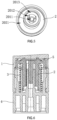
FIG. 1 is a cross-sectional structural schematic diagram of an embodiment of the present invention, in which the framed portion is enlarged, and the arrows indicate the direction of air inlet and liquid outlet, respectively. -
FIG. 2 is a schematic diagram of the three-dimensional structure ofFIG. 1 . -
FIG. 3 is a schematic diagram of the exploded structure ofFIG. 2 , in which the dotted line is the spring. -
FIG. 4 is a schematic diagram of the bottom exploded structure ofFIG. 3 . -
FIG. 5 is a schematic diagram of the bottom structure of the inner plug ofFIG. 4 . -
FIG. 6 is a schematic diagram of the sectional structure of the second embodiment of the present invention. - Serial numbers and names of the accompanying drawings: 1. Head cap, 101. Cap mouth bar, 2. Inner plug, 201. Lower bush, 2011. Central column, 2012. Wall guide groove, 2013. Lower bush groove, 202. Upper spring plug, 2021. Lower ring groove, 2022. Top cover groove, 203. Thru-hole, 3. Spring, 4. Large ring, 401. Plunger hole, 4011. Step bar, 402. Bush groove, 403. Spring groove, 404. Groove mouth ring, 405. Suction tube hole, 406. Bottle mouth bar, 407. Inner bottle groove, 5. Cap piece, 501, Sealing skirt, 502. Locating cylindrical pin.
- The structure of the present invention is now further described in conjunction with the accompanying drawings. As shown in
FIGS. 1 -5 , the small spray pump head comprises of ahead cap 1, aninner plug 2, aspring 3, and alarge ring 4, the head cap has a spray hole on one side, while the inner plug is placed in the liquid outlet hole of the large ring. The spring is a metal spring. The particular structure is described below: the liquid outlet hole of the large ring is aplunger hole 401, with the plunger hole on top of the large ring communicating with thesuction tube hole 405 on the bottom. The plunger hole of the large ring has abush groove 402 and aspring groove 403 sequentially disposed around its outer diameter, with the spring placed in the spring groove; theinner plug 2 is T-shaped, with thelower sleeve level 201 having anupper spring plug 202. The lower bush of the inner plug also has acentral column 2011 and awall guide groove 2012 in the lower bush. The said wall guide groove is connected to the thru-hole 203 on top of the inner hole; the central column of the inner plug is inserted into the plunger hole of the large ring, while the lower bush of the inner plug is inserted into the bush groove of the large ring. One end of the spring is placed against the bottom inside of the spring groove of the large ring, with the other end placed against thelower ring groove 2021 on the bottom of the upper spring plug of the inner plug; the outer diameter of the lower ring groove of the inner plug is an elastic sleeve, a spring cavity is formed as the groove mouth at the lower ring groove of the inner plug is placed against the groove mouth outside of the spring groove of the large spring, the spring is then sealed within this cavity. Atop cover groove 2022 is disposed on top of the upper spring plug of the inner plug, and an upwardlyprotruding cover piece 5 is disposed in the top cover groove of the inner plug. The thru-hole of the inner plug is located within the said cover piece: Upon pressing the head cap, the inner plug moves downward to cause deformation of the spring, cover piece, and the elastic sleeve of the inner plug, the thru-hole of the inner plug is sealed by the cover piece, allowing liquid to be sprayed through the spray hole of the head cap via the wall guide groove of the inner plug, and by means of atomization resulting from the deformation of cover piece and the elastic sleeve of the inner plug. There are retained seals between the inner diameter of the head cap and the outer diameter of the upper spring plug of the inner plug, and the outer diameter of the mouth of the elastic groove of the large ring; upon releasing the head cap, the inner plug moves upwardly and the spring, the cover piece and the inner plug of the elastic sleeve return to the original positions, the cover piece at the thru-hole of the inner hole opens, allowing air to enter the large ring via the clearance formed between the inner diameter of the head cap and the large ring, inner plug, or via the spray hole of the head cap, and the wall guide groove of the inner plug. - The mouth edge of the said
cover piece 5 is provided with a downwardly protruding sealingskirt 501, or the outer radial direction of the sealing skirt is upwardly upturned to fit into the beveled edge of the inner diameter of the cap groove at the top of the inner plug, and the sealing skirt of the cover piece is placed and sealed against the inner thru-hole in the cap groove at the top of the inner plug; the said cover piece is provided with a raised locatingcylindrical pin 502 in the middle of the top of said cover piece, the locating cylindrical pin is inserted into the corresponding groove at the top of the head cap. Alternatively, as illustrated inFIG. 6 , the cover piece features a sealing skirt that is downwardly protruding along the mouth edge, while a raised locating ring bar is located at the top center of the cover piece for insertion into a matching groove within the head cap. - A raised
step bar 4011 is provided at the chamfer of the outer diameter of the plunger hole at the bottom of the bush groove of the said large ring, the bottom part of the lower bush to which the step bar corresponds to the inner plug is provided with alower bush groove 2013. Upon pressing the head cap, the lower bush of the inner plug is constrained by the step bar of the large ring, and the mouth of the lower ring groove of the inner plug deforms outwardly and is sealed to the inner diameter of the head cap. The bottom cap mouth of the said head cap is provided with an inwardly protrudingcap mouth bar 101, the outer diameter of the cap mouth bar of the large ring in the head cap above the cap mouth bar is provided with a raisedgroove ring 404, the groove mouth ring of the large ring is inserted into the cap mouth bar of the head cap by interference fit, the lower outer diameter of the cap mouth ring is sealed against the cap mouth bar of the head cap. The bush hole outer diameter at the lower bush of the inner plug is outwardly protruding and stretching out, and is placed and sealed against the inner wall at the bush groove of the large ring; the spray hole of the head cap is located on one side above where the groove mouth outer diameter of the said lower ring groove is outwardly protruding and stretching out. The inner diameter of the groove mouth at the lower ring groove of the said inner plug is provided with an inner pour outlet underneath the groove mouth, and the said inner pour outlet is located above the groove mouth outer diameter of the spring groove of the large spring; upon pressing the head cap, the inner pour outlet of the inner plug is constrained against the groove mouth outer diameter of the large spring. The inner wall of the lower bush of the said inner plug is provided with three equally spaced wall guide grooves, correspond to the three thru-holes on top of the inner plug. - The ring mouth inner diameter at the bottom of the large ring is provided with a raised
bottle mouth bar 406. The large ring is snap-fit to the mouth of the bottle body through the bottle mouth bar. The inner diameter of the bottle mouth bar of the said large ring is provided with a raisedinner bottle groove 407, the large ring is snap-fit to the mouth of the outer bottle body, and the large ring is securely set to the mouth of the inner bottle body. - When used, the suction tube hole of the large ring is filled with a suction tube, the large ring is set into the mouth of the outer bottle body and the mouth of the inner bottle body at the same time. Upon pressing the head cap, the inner plug moves downward to cause deformation of the spring, cover piece, and the elastic sleeve of the inner plug, the groove mouth of the lower ring groove of the inner plug is outwardly deformed and sealed in the inner diameter of the head cap, allowing liquid to be sprayed through the spray hole of the head cap via the wall guide groove of the inner plug, and by means of atomization resulting from the deformation of cover piece and the elastic sleeve of the inner plug. Upon releasing the head cap, the inner plug moves upwardly and the spring, the cover piece and the inner plug of the elastic sleeve return to the original positions, allowing air to enter the pump head, waiting for the next use by pressing of the head cap.
Claims (10)
- A small spray pump head, comprising of a head cap (1), an inner plug (2), a spring (3), and a large ring (4), the head cap has a spray hole on one side, while the inner plug is placed in the liquid outlet hole of the large ring (4); wherein the liquid outlet hole of the large ring (4) is a plunger hole (401), with the plunger hole (401) on top of the large ring communicating with a suction tube hole (406) on the bottom wherein- the plunger hole (401) of the large ring has a bush groove (402) and a spring groove (403) sequentially disposed around its outer diameter, with the spring (3) placed in the spring groove (403);- the inner plug (2) is T-shaped, with a lower bush (201) having an upper spring plug (202), the lower bush of the inner plug having a central column (2011) and also a wall guide groove (2012) in the lower bush, the said wall guide groove (2012) being connected to a thru-hole (203) on top of the inner hole; the central column of the inner plug being inserted into the plunger hole of the large ring, while the lower bush (201) of the inner plug (2) being inserted into the bush groove (402) of the large ring (4), one end of the spring (3) being placed against the bottom inside of the spring groove (403) of the large ring (4), with the other end placed against a lower ring groove (2021) on the bottom of the upper spring plug (202) of the inner plug (2); the outer diameter of the lower ring groove (2021) of the inner plug being an elastic sleeve, wherein a spring cavity is formed as a groove mouth at the lower ring groove (2021) of the inner plug is placed against a groove mouth outside of the spring groove (403) of the large spring, the spring being sealed within this cavity; a top cover groove (2022) being disposed on top of the upper spring plug (202) of the inner plug (2), and an upwardly protruding cover piece (5) being disposed in the top cover groove (2022) of the inner plug., the thru-hole (203) of the inner plug located within the said cover piece (5): wherein upon pressing the head cap (1), the inner plug (2) moves downward to cause deformation of the spring (3), cover piece (5), and the elastic sleeve of the inner plug, the thru-hole of the inner plug (203) sealed by the cover piece (5), allowing liquid to be sprayed through a spray hole of the head cap via the wall guide groove (2012) of the inner plug, and by means of atomization resulting from the deformation of cover piece and the elastic sleeve of the inner plug, wherein there are retained seals between the inner diameter of the head cap (1) and the outer diameter of the upper spring plug of the inner plug, and the outer diameter of the mouth of the elastic groove of the large ring; upon releasing the head cap, the inner plug moves upwardly and the spring, the cover piece and the inner plug of the elastic sleeve return to the original positions, the cover piece at the thru-hole of the inner hole opens, allowing air to enter the large ring via the clearance formed between the inner diameter of the head cap and the large ring, inner plug, or via the spray hole of the head cap, and the wall guide groove of the inner plug.
- A small spray pump head according to Claim 1, wherein the mouth edge of the said cover piece (5) is provided with a downwardly protruding sealing skirt (501), or the outer radial direction of the sealing skirt is upwardly upturned to fit into the beveled edge of the inner diameter of the cap groove (2022) at the top of the inner plug (2), and the sealing skirt of the cover piece is placed and sealed against the inner thru-hole (203) in the cap groove at the top of the inner plug.
- A small spray pump head according to Claim 2, wherein the said cover piece (5) is provided with a raised locating pin (502) or locating ring bar in the middle of the top of said cover piece (5), the locating cylindrical pin or the locating ring bar is inserted into the corresponding groove at the top of the head cap (1).
- A small spray pump head according to Claim 1, wherein a raised step bar (4011) is provided at the chamfer of the outer diameter of the plunger hole (401) at the bottom of the bush groove (402) of the said large ring (4), the bottom part of the lower bush (201) to which the step bar corresponds to the inner plug (2) is provided with a lower bush groove (2013). Upon pressing the head cap (1), the lower bush of the inner plug is constrained by the step bar of the large ring, and the mouth of the lower ring groove of the inner plug deforms outwardly and is sealed to the inner diameter of the head cap.
- A small spray pump head according to Claim 1, wherein the bottom cap mouth of the said head cap (1) is provided with an inwardly protruding cap mouth bar (101), the outer diameter of the cap mouth bar of the large ring (4) in the head cap above the cap mouth bar is provided with a raised groove ring (404), the groove mouth ring of the large ring is inserted into the cap mouth bar of the head cap by interference fit, the lower outer diameter of the cap mouth ring is sealed against the cap mouth bar of the head cap.
- A small spray pump head according to Claim 1, wherein the groove mouth outer diameter of the lower ring groove (2021) of the upper spring plug (202) in the said inner plug (2) is outwardly protruding and stretching out, and is placed and sealed against the inner diameter of the head cap (1); the bush hole outer diameter at the lower bush (201) of the inner plug is outwardly protruding and stretching out, and is placed and sealed against the inner wall at the bush groove (402) of the large ring (4); the spray hole of the head cap is located on one side above where the groove mouth outer diameter of the said lower ring groove is outwardly protruding and stretching out.
- A small spray pump head according to Claim 6, wherein the inner diameter of the groove mouth at the lower ring groove (2021) of the said inner plug (2) is provided with an inner pour outlet underneath the groove mouth, and the said inner pour outlet is located above the groove mouth outer diameter of the spring groove (403) of the large spring; upon pressing the head cap (1), the inner pour outlet of the inner plug is constrained against the groove mouth outer diameter of the large spring.
- A small spray pump head according to Claim 1, wherein the inner wall of the lower bush (201) of the said inner plug is provided with three equally spaced wall guide grooves (2012), correspond to the three thru-holes (203) on top of the inner plug.
- A small spray pump head according to Claim 1, wherein the ring mouth inner diameter at the bottom of the large ring (4) is provided with a raised bottle mouth bar (406) or ring mouth inner threads. The large ring is snap-fit to the mouth of the bottle body through the bottle mouth bar, or the large ring is revolvably fixed to the bottle mouth outer threads of the bottle body through the ring mouth inner threads.
- A small spray pump head according to Claim 9, wherein the inner diameter of the bottle mouth bar (406) of the said large ring (4) is provided with a raised inner bottle groove (407), the large ring is snap-fit to the mouth of the outer bottle body, and the large ring is securely set to the mouth of the inner bottle body.
Applications Claiming Priority (1)
| Application Number | Priority Date | Filing Date | Title |
|---|---|---|---|
| CN202311628676.0A CN117602221B (en) | 2023-11-30 | 2023-11-30 | Small spray pump head |
Publications (2)
| Publication Number | Publication Date |
|---|---|
| EP4563240A1 true EP4563240A1 (en) | 2025-06-04 |
| EP4563240B1 EP4563240B1 (en) | 2026-02-18 |
Family
ID=89945950
Family Applications (1)
| Application Number | Title | Priority Date | Filing Date |
|---|---|---|---|
| EP24175811.9A Active EP4563240B1 (en) | 2023-11-30 | 2024-05-14 | Small spray pump head |
Country Status (3)
| Country | Link |
|---|---|
| US (1) | US20250178009A1 (en) |
| EP (1) | EP4563240B1 (en) |
| CN (1) | CN117602221B (en) |
Citations (3)
| Publication number | Priority date | Publication date | Assignee | Title |
|---|---|---|---|---|
| CN103842033A (en) | 2011-10-12 | 2014-06-04 | 万通集团公司 | Fan spray structure for use in dispensing actuator |
| US20180318863A1 (en) * | 2015-10-07 | 2018-11-08 | Rpc Bramlage Gmbh | Dispenser in particular for liquid to pasty substances |
| CN110789842A (en) | 2019-10-25 | 2020-02-14 | 浙江正庄实业有限公司 | Antibacterial high-molecular press type small spray head and preparation method thereof |
Family Cites Families (4)
| Publication number | Priority date | Publication date | Assignee | Title |
|---|---|---|---|---|
| FR2711554B1 (en) * | 1993-10-22 | 1995-12-22 | Oreal | Distribution unit with controlled air intake. |
| CN111096534B (en) * | 2019-12-30 | 2023-09-15 | 浙江正庄实业有限公司 | Antibacterial polymer strong-pressure single-layer vacuum bottle and its material preparation method |
| CN111096536B (en) * | 2019-12-30 | 2024-03-15 | 浙江正庄实业有限公司 | Antibacterial high-rigidity single-layer flat lotion bottle and material preparation method thereof |
| CN111422488B (en) * | 2020-04-21 | 2022-03-29 | 泰马克精密铸造(苏州)有限公司 | Cosmetic bottle cap capable of automatically pumping liquid |
-
2023
- 2023-11-30 CN CN202311628676.0A patent/CN117602221B/en active Active
-
2024
- 2024-05-14 EP EP24175811.9A patent/EP4563240B1/en active Active
- 2024-05-15 US US18/664,672 patent/US20250178009A1/en active Pending
Patent Citations (3)
| Publication number | Priority date | Publication date | Assignee | Title |
|---|---|---|---|---|
| CN103842033A (en) | 2011-10-12 | 2014-06-04 | 万通集团公司 | Fan spray structure for use in dispensing actuator |
| US20180318863A1 (en) * | 2015-10-07 | 2018-11-08 | Rpc Bramlage Gmbh | Dispenser in particular for liquid to pasty substances |
| CN110789842A (en) | 2019-10-25 | 2020-02-14 | 浙江正庄实业有限公司 | Antibacterial high-molecular press type small spray head and preparation method thereof |
Also Published As
| Publication number | Publication date |
|---|---|
| CN117602221B (en) | 2025-10-10 |
| EP4563240B1 (en) | 2026-02-18 |
| US20250178009A1 (en) | 2025-06-05 |
| CN117602221A (en) | 2024-02-27 |
Similar Documents
| Publication | Publication Date | Title |
|---|---|---|
| US4277001A (en) | Invertible miniature atomizer of manual type | |
| US4173297A (en) | Non-throttling manually reciprocated plunger pump for consumer-type liquid dispensing containers | |
| EP2514532B1 (en) | Dispenser assembly for a fluid dispensing receptacle and method of assembling same | |
| US12098713B2 (en) | Vacuum pump | |
| US3724726A (en) | Pump for spraying | |
| US4503996A (en) | Liquid atomizer having a double-acting pump | |
| JPS6027470Y2 (en) | pump dispenser | |
| EP0374348B1 (en) | Improved precompression pump, for dispensing liquid products from vessels | |
| US12508612B2 (en) | Device for dispensing a fluid product | |
| US5242089A (en) | Miniature pump sprayer | |
| US20050167452A1 (en) | Perfume sample device | |
| US9352346B2 (en) | Fluid dispenser | |
| US3985299A (en) | Spray head | |
| CN113287853A (en) | Multifunctional cosmetic bottle | |
| US3029742A (en) | Dispensing pump for fluids | |
| JPS6319713B2 (en) | ||
| EP4563240B1 (en) | Small spray pump head | |
| US4311256A (en) | Mechanical breakup actuator | |
| US20060169724A1 (en) | Fluid product dispensing device | |
| US5370280A (en) | Valve for a sprayer | |
| KR102302726B1 (en) | mist sprayer which can mist up and down | |
| JPS6026844Y2 (en) | Manual small sprayer | |
| CN212139693U (en) | Perfume bottle with adjustable spraying amount | |
| JP4877913B2 (en) | INJECTION DEVICE AND INJECTOR | |
| CN221439022U (en) | A perfume pump capable of effectively preventing a middle sleeve from loosening |
Legal Events
| Date | Code | Title | Description |
|---|---|---|---|
| PUAI | Public reference made under article 153(3) epc to a published international application that has entered the european phase |
Free format text: ORIGINAL CODE: 0009012 |
|
| STAA | Information on the status of an ep patent application or granted ep patent |
Free format text: STATUS: THE APPLICATION HAS BEEN PUBLISHED |
|
| AK | Designated contracting states |
Kind code of ref document: A1 Designated state(s): AL AT BE BG CH CY CZ DE DK EE ES FI FR GB GR HR HU IE IS IT LI LT LU LV MC ME MK MT NL NO PL PT RO RS SE SI SK SM TR |
|
| STAA | Information on the status of an ep patent application or granted ep patent |
Free format text: STATUS: REQUEST FOR EXAMINATION WAS MADE |
|
| GRAP | Despatch of communication of intention to grant a patent |
Free format text: ORIGINAL CODE: EPIDOSNIGR1 |
|
| STAA | Information on the status of an ep patent application or granted ep patent |
Free format text: STATUS: GRANT OF PATENT IS INTENDED |
|
| 17P | Request for examination filed |
Effective date: 20250918 |
|
| RIC1 | Information provided on ipc code assigned before grant |
Ipc: B05B 11/10 20230101AFI20250924BHEP |
|
| INTG | Intention to grant announced |
Effective date: 20251014 |
|
| GRAS | Grant fee paid |
Free format text: ORIGINAL CODE: EPIDOSNIGR3 |
|
| GRAA | (expected) grant |
Free format text: ORIGINAL CODE: 0009210 |
|
| STAA | Information on the status of an ep patent application or granted ep patent |
Free format text: STATUS: THE PATENT HAS BEEN GRANTED |
|
| AK | Designated contracting states |
Kind code of ref document: B1 Designated state(s): AL AT BE BG CH CY CZ DE DK EE ES FI FR GB GR HR HU IE IS IT LI LT LU LV MC ME MK MT NL NO PL PT RO RS SE SI SK SM TR |
|
| REG | Reference to a national code |
Ref country code: CH Ref legal event code: F10 Free format text: ST27 STATUS EVENT CODE: U-0-0-F10-F00 (AS PROVIDED BY THE NATIONAL OFFICE) Effective date: 20260218 Ref country code: GB Ref legal event code: FG4D |
|
| REG | Reference to a national code |
Ref country code: IE Ref legal event code: FG4D |
|
| REG | Reference to a national code |
Ref country code: DE Ref legal event code: R096 Ref document number: 602024002592 Country of ref document: DE |
|
| PGFP | Annual fee paid to national office [announced via postgrant information from national office to epo] |
Ref country code: FR Payment date: 20260330 Year of fee payment: 3 |
|
| REG | Reference to a national code |
Ref country code: NL Ref legal event code: MP Effective date: 20260218 |
|
| PG25 | Lapsed in a contracting state [announced via postgrant information from national office to epo] |
Ref country code: RS Free format text: LAPSE BECAUSE OF FAILURE TO SUBMIT A TRANSLATION OF THE DESCRIPTION OR TO PAY THE FEE WITHIN THE PRESCRIBED TIME-LIMIT Effective date: 20260518 |
|
| PG25 | Lapsed in a contracting state [announced via postgrant information from national office to epo] |
Ref country code: ES Free format text: LAPSE BECAUSE OF FAILURE TO SUBMIT A TRANSLATION OF THE DESCRIPTION OR TO PAY THE FEE WITHIN THE PRESCRIBED TIME-LIMIT Effective date: 20260218 |
|
| PG25 | Lapsed in a contracting state [announced via postgrant information from national office to epo] |
Ref country code: PL Free format text: LAPSE BECAUSE OF FAILURE TO SUBMIT A TRANSLATION OF THE DESCRIPTION OR TO PAY THE FEE WITHIN THE PRESCRIBED TIME-LIMIT Effective date: 20260218 |
|
| PG25 | Lapsed in a contracting state [announced via postgrant information from national office to epo] |
Ref country code: GR Free format text: LAPSE BECAUSE OF FAILURE TO SUBMIT A TRANSLATION OF THE DESCRIPTION OR TO PAY THE FEE WITHIN THE PRESCRIBED TIME-LIMIT Effective date: 20260519 |
|
| REG | Reference to a national code |
Ref country code: LT Ref legal event code: MG9D |
|
| PG25 | Lapsed in a contracting state [announced via postgrant information from national office to epo] |
Ref country code: LT Free format text: LAPSE BECAUSE OF FAILURE TO SUBMIT A TRANSLATION OF THE DESCRIPTION OR TO PAY THE FEE WITHIN THE PRESCRIBED TIME-LIMIT Effective date: 20260218 |
|
| PGFP | Annual fee paid to national office [announced via postgrant information from national office to epo] |
Ref country code: DE Payment date: 20260330 Year of fee payment: 3 |
|
| PG25 | Lapsed in a contracting state [announced via postgrant information from national office to epo] |
Ref country code: NO Free format text: LAPSE BECAUSE OF FAILURE TO SUBMIT A TRANSLATION OF THE DESCRIPTION OR TO PAY THE FEE WITHIN THE PRESCRIBED TIME-LIMIT Effective date: 20260518 |
|
| PG25 | Lapsed in a contracting state [announced via postgrant information from national office to epo] |
Ref country code: SE Free format text: LAPSE BECAUSE OF FAILURE TO SUBMIT A TRANSLATION OF THE DESCRIPTION OR TO PAY THE FEE WITHIN THE PRESCRIBED TIME-LIMIT Effective date: 20260218 Ref country code: FI Free format text: LAPSE BECAUSE OF FAILURE TO SUBMIT A TRANSLATION OF THE DESCRIPTION OR TO PAY THE FEE WITHIN THE PRESCRIBED TIME-LIMIT Effective date: 20260218 Ref country code: AT Free format text: LAPSE BECAUSE OF FAILURE TO SUBMIT A TRANSLATION OF THE DESCRIPTION OR TO PAY THE FEE WITHIN THE PRESCRIBED TIME-LIMIT Effective date: 20260218 |
|
| REG | Reference to a national code |
Ref country code: AT Ref legal event code: MK05 Ref document number: 1887533 Country of ref document: AT Kind code of ref document: T Effective date: 20260218 |
|
| PG25 | Lapsed in a contracting state [announced via postgrant information from national office to epo] |
Ref country code: HR Free format text: LAPSE BECAUSE OF FAILURE TO SUBMIT A TRANSLATION OF THE DESCRIPTION OR TO PAY THE FEE WITHIN THE PRESCRIBED TIME-LIMIT Effective date: 20260218 |
|
| PG25 | Lapsed in a contracting state [announced via postgrant information from national office to epo] |
Ref country code: PT Free format text: LAPSE BECAUSE OF FAILURE TO SUBMIT A TRANSLATION OF THE DESCRIPTION OR TO PAY THE FEE WITHIN THE PRESCRIBED TIME-LIMIT Effective date: 20260618 Ref country code: IS Free format text: LAPSE BECAUSE OF FAILURE TO SUBMIT A TRANSLATION OF THE DESCRIPTION OR TO PAY THE FEE WITHIN THE PRESCRIBED TIME-LIMIT Effective date: 20260618 |
|
| PG25 | Lapsed in a contracting state [announced via postgrant information from national office to epo] |
Ref country code: NL Free format text: LAPSE BECAUSE OF FAILURE TO SUBMIT A TRANSLATION OF THE DESCRIPTION OR TO PAY THE FEE WITHIN THE PRESCRIBED TIME-LIMIT Effective date: 20260218 |
|
| PG25 | Lapsed in a contracting state [announced via postgrant information from national office to epo] |
Ref country code: LV Free format text: LAPSE BECAUSE OF FAILURE TO SUBMIT A TRANSLATION OF THE DESCRIPTION OR TO PAY THE FEE WITHIN THE PRESCRIBED TIME-LIMIT Effective date: 20260218 |
|
| PG25 | Lapsed in a contracting state [announced via postgrant information from national office to epo] |
Ref country code: BG Free format text: LAPSE BECAUSE OF FAILURE TO SUBMIT A TRANSLATION OF THE DESCRIPTION OR TO PAY THE FEE WITHIN THE PRESCRIBED TIME-LIMIT Effective date: 20260218 |