EP4563235A1 - A frame for a decanter centrifuge - Google Patents
A frame for a decanter centrifuge Download PDFInfo
- Publication number
- EP4563235A1 EP4563235A1 EP23213456.9A EP23213456A EP4563235A1 EP 4563235 A1 EP4563235 A1 EP 4563235A1 EP 23213456 A EP23213456 A EP 23213456A EP 4563235 A1 EP4563235 A1 EP 4563235A1
- Authority
- EP
- European Patent Office
- Prior art keywords
- longitudinal direction
- frame
- box
- shaped beam
- reinforcement plates
- Prior art date
- Legal status (The legal status is an assumption and is not a legal conclusion. Google has not performed a legal analysis and makes no representation as to the accuracy of the status listed.)
- Granted
Links
Images


Classifications
-
- B—PERFORMING OPERATIONS; TRANSPORTING
- B04—CENTRIFUGAL APPARATUS OR MACHINES FOR CARRYING-OUT PHYSICAL OR CHEMICAL PROCESSES
- B04B—CENTRIFUGES
- B04B1/00—Centrifuges with rotary bowls provided with solid jackets for separating predominantly liquid mixtures with or without solid particles
- B04B1/20—Centrifuges with rotary bowls provided with solid jackets for separating predominantly liquid mixtures with or without solid particles discharging solid particles from the bowl by a conveying screw coaxial with the bowl axis and rotating relatively to the bowl
-
- B—PERFORMING OPERATIONS; TRANSPORTING
- B04—CENTRIFUGAL APPARATUS OR MACHINES FOR CARRYING-OUT PHYSICAL OR CHEMICAL PROCESSES
- B04B—CENTRIFUGES
- B04B7/00—Elements of centrifuges
- B04B7/02—Casings; Lids
-
- F—MECHANICAL ENGINEERING; LIGHTING; HEATING; WEAPONS; BLASTING
- F16—ENGINEERING ELEMENTS AND UNITS; GENERAL MEASURES FOR PRODUCING AND MAINTAINING EFFECTIVE FUNCTIONING OF MACHINES OR INSTALLATIONS; THERMAL INSULATION IN GENERAL
- F16M—FRAMES, CASINGS OR BEDS OF ENGINES, MACHINES OR APPARATUS, NOT SPECIFIC TO ENGINES, MACHINES OR APPARATUS PROVIDED FOR ELSEWHERE; STANDS; SUPPORTS
- F16M1/00—Frames or casings of engines, machines or apparatus; Frames serving as machinery beds
- F16M1/08—Frames or casings of engines, machines or apparatus; Frames serving as machinery beds characterised by being built-up of sheet material or welded parts
Definitions
- the present invention relates to a frame for a decanter centrifuge, a decanter centrifuge and a method of producing a frame for a decanter centrifuge.
- a decanter centrifuge is a centrifuge that during operation performs a centrifugal sedimentation process on a suspension of solid particles and a liquid.
- the decanter centrifuge comprises a bowl rotationally mounted on a frame.
- the suspension forms a ring-shaped liquid layer along the interior wall of the bowl under the action of centrifugal force, in which the denser solid particles settle to the drum wall radially to form a sludge, and the clarified liquid is discharged through a bowl overflow.
- the sediment is discharged by mechanical methods, typically using an Archimedean screw conveyor.
- the bowl is typically supported horizontally on the frame by a bearing at either side of the bowl. Further, a drive motor, a gear box and, where necessary, a back-drive motor are as well mounted and supported by the frame.
- the rotating components of the decanter centrifuge, such as the bowl, are surrounded by a protective cover and a casing for collecting the separated solids and liquid.
- the casing typically forms an integrated part of the frame.
- the cover is mounted separately on the frame.
- the frame is typically made up of elongated metal box-shaped beams, which in turn are supported on a ground support connected to a foundation at the site of the installation.
- the ground support is typically in the form of four legs providing stability.
- the bowl is typically rotating at a speed of 2000rpm-6000rpm during operation. When the bowl is rotating at such high speeds it is inevitable that vibrations will occur. The vibrations will be induced into the frame and must be absorbed by the frame without causing any resonance effects in the frame. Using a higher bowl speed will induce higher frequencies into the frame. If the frequencies induced during operations cause resonance effects in the frame, it may result in significantly stronger vibrations in the frame and possibly damage to the frame. To avoid inducing resonance effects from the bowl into the frame, the frame must be made having an eigenfrequency (or natural frequency) being significantly higher than the frequency of the vibration induced into the frame by the rotation of the bowl.
- the eigenfrequency of the frame is dependent on the bending rigidity of the frame and inversely dependent on the mass of the frame. More specifically, the eigenfrequency increases when the bending rigidity increases and decreases when the mass increases. Making the frame longer in the longitudinal direction while keeping the other dimensions of the frame unchanged will reduce the bending rigidity as the frame will have to be provided with longer box-shaped beams. It will also increase the mass, as more material will be used when making the frame longer. Thus, making the frame longer will significantly decrease the eigenfrequency of the frame. When the eigenfrequency of the frame approaches the eigenfrequency of the rotating bowl, resonance effects will occur.
- JP 7234489 describes a centrifugal separator having a frame having a hollow first frame member extending in a first direction, a hollow second frame member extending in a second direction and a connection portion connecting the first frame member to the second frame member.
- the connection portion including a first fixing portion being fixed to an end portion of the first frame member and a second fixing portion being fixed to an end portion of the second frame member.
- a reinforcing part being bridged between the first fixing part and the second fixing part and extending in a direction intersecting the first direction and the second direction.
- JP07071052 describes a screw conveyer having reinforcing members fixed between a reinforcing ring and a casing.
- KR200396783 describes a screw dehydrator with reinforcing plates installed in a semicircular ring shape.
- CN212861338 describes vehicle energy absorption box having a reinforcing piece.
- the object of the present invention is thus to provide technologies for increasing the length of the bowl of the decanter centrifuge while preventing resonance phenomena in the frame.
- the above object is realized by a frame for a decanter centrifuge, the frame defining a longitudinal direction, a vertical direction extending transversally relative to the longitudinal direction and a transverse direction extending transversally relative to the longitudinal direction and the vertical direction, the frame comprising:
- the frame is made up of the two box-shaped beams extending in the longitudinal direction and the at least two connecting elements between the two box-shaped beams in the transverse direction.
- the connecting elements can be used for supporting e.g. the bearings of the rotatable bowl of the decanter centrifuge, the casing below the bowl, the gearbox and the motors.
- the box-shaped beam is made of metal material and have an overall rectangular shape.
- the box-shaped beam is made up by the vertical plate and the C-shaped beam.
- the C-shaped beam is typically made as an elongated metal element which has been formed in a C-shape having two horizontal flanges and a vertical web interconnecting the two horizontal flanges edge-to-edge. An interior channel is thus formed between the vertical web and the two horizonal flanges.
- the C-shaped beam is reinforced by the reinforcement plates which are attached on the web and on the two horizontal flanges facing the interior channel of the C-shaped beam. In this way the reinforcement plates are invisible from the outside and they thus do not affect the physical appearance of the frame.
- the vertical plate is attached edge-to-edge to the two horizontal flanges opposite the vertical web to form a rectangular and box-shaped beam.
- the box-shaped beam is thus hollow.
- the reinforcement plates allow the box shaped beams to be longer while maintaining the bending rigidity of the frame, thereby maintaining the eigenfrequency of the frame.
- adding the reinforcement plates makes the frame heavier. This is negative as it decreases the eigenfrequency of the frame.
- the reinforcement plates must not necessarily extend the full length of the box-shaped beam, i.e. the full length between the first end and the second end.
- the reinforcement plates can extend only a part of the distance between the first end and the second end.
- the reinforcement plates can be attached between positions along the longitudinal direction of the box shaped beam having higher bending stress and omitting the locations along the longitudinal direction of the box shaped beam having lower bending stress.
- the ground supports are supporting the box shaped beams at a third and fourth position along the longitudinal direction.
- Each box shaped beam is thereby supported on the ground, i.e. a factory floor or the like, by the two ground supports which are extending downwards in the vertical direction and support the frame on the ground.
- the third position being located adjacent the first end and the fourth position being located adjacent the second end. It is understood to mean that the third position is closer to the first end than the centre point of the frame in the longitudinal direction whereas the fourth position is closer to the second end than the centre point of the frame in the longitudinal direction.
- the bending stress will be low adjacent the first and second edges, i.e. near the ground supports, and higher near the longitudinal centre point of the box shaped beams, i.e. far from the ground supports.
- the reinforcing plates can thus extend only a part of the distance between the first end and the second end without significantly reducing the bending stress as the bending stress is low adjacent the first and second edges. In this way the increase in mass of the frame will be lower, allowing the eigenfrequency of the frame to be higher.
- the C-shaped beam being manufactured as a unitary element. In this way there will be no joints in the C-shaped beam, allowing it to be more rigid and easier to produce.
- the C-shaped beam can e.g., be made by pressing, casting or moulding.
- the box shaped beam is made of metal, such as cast iron or carbon steel.
- Metal such as cast iron or carbon steel is typically used for the box shaped beam due to the increased rigidity and reduced maintenance requirements.
- the reinforcement plates are attached by spot welding and the reinforcement plates are provided with holes for the spot welding. In this way the reinforcement plates are securely fastened to the C-shaped beam, increasing the bending rigidity.
- the reinforcement plates are attached by fillet welding and the reinforcement plates define a gap in-between themselves for the fillet welding.
- the bending rigidity can be increased.
- the length between the first end and the second end is at least 20% longer than the distance between the third end and the fourth end, preferably 30% longer, more preferably 40% longer.
- the reinforcement plates are substantially centred between the first end and the second end.
- the reinforcement plates are thus placed at the location where they have the most effect, and that is close to the centre where the bending stress is the highest.
- the distance between the first end and the second end being 5-10 meters, preferably 6-9 meters, and the distance between the third end and the fourth end being 2-5 meters, preferably 3-4 meters.
- Standard decanter centrifuges are up to 5m long. The length of the decanter centrifuge can be increased by including the length of the frame and the reinforcing plates.
- the third position is located between the first end and the third end, and, the fourth position being located between the second end and the fourth end.
- the reinforcement plates must no extend beyond the third and fourth positions, respectively, as the third and fourth positions are the locations of the ground supports.
- the first ground support and the second ground support are made as box-shaped legs being attached to one of the respective elongated box-shaped beams.
- the frame is supported by four legs extending from the box-shaped beams to the ground.
- the legs can be made hollow, similar to the box-shaped beams.
- the at least one of the two connecting elements interconnecting the first ends of the parallel box-shaped beams, and, at least one other of the two connecting elements interconnecting the second ends of the parallel box-shaped beams. Interconnecting the ends of the parallel box-shaped beams further improves the bending rigidity of the frame.
- decanter centrifuge comprising a decanter bowl mounted on a frame according to the first aspect.
- the above object is realized by method of producing a frame for a decanter centrifuge, the frame defining a longitudinal direction, a vertical direction extending transversally relative to the longitudinal direction and a transverse direction extending transversally relative to the longitudinal direction and the vertical direction, the method comprising the following steps:
- the method according to the third aspect can be used for producing the frame according to the first aspect.
- FIG. 1 is a perspective view of a decanter centrifuge 10 according to the present invention.
- the decanter centrifuge 10 comprises a frame 12 and a cover 14 mounted on the frame 12.
- the decanter centrifuge 10 comprises rotating components (not visible) which are rotatably mounted on the frame 12 below the cover 14.
- the frame 12 comprises two box-shaped beams 16 extending parallel to each other in the longitudinal direction L between a first end 22a and a second end 22b.
- the frame 12 further comprising at least two connecting elements 18 connecting the box-shaped beams 16 at a first position 24a and a second position 24b along the longitudinal direction L.
- the frame 12 further comprises four ground supports 20 in the form of legs extending downwards from the box-shaped beams 16 in the vertical direction V for supporting the decanter centrifuge 10 on the ground (not shown).
- the ground (not shown) may be a factory floor or the like.
- the vertical direction V being transversal relative to their longitudinal direction L.
- the ground supports 20 being connected to the box-shaped beams at a third position 24c and a fourth position 24d.
- the third position 24c being located between the first end 22a and a centre point C between the first end 22a and the second end 22b, and, the fourth position 24d being located between the second end 22b and the centre point C.
- a drive motor 26 and a back drive motor 28 is supported by the frame 12.
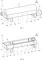
- FIG. 2 is a cut-out perspective view of a frame 12 according to the present invention.
- Reinforcement plates 30 are located within the box shaped beam 16.
- the reinforcement plates 30 extend between a third end 22c and a fourth end 22d.
- the third end 22c is located between the third position 24c and the centre point C, whereas the fourth end 22d is located between the fourth position and the centre point C.
- the third position 24c is located between the first end 22a and the third end 22c, and, the fourth position 24d being located between the second end 22b and the fourth end 22d.
- the reinforcement plates 30 add bending rigidity to the box-shaped beam 16 for increasing the eigenfrequency of the frame 12.
- the reinforcement plates 30 do not extend all the way to the first end 22a and second end 22b as the added weight will decrease the eigenfrequency whereas the bending rigidity is not increased by the added plates adjacent the first end 22a and second end 22b. In this way the frame 12 can be made longer and consequently the rotating components, i.e., the bowl (not shown), can be made longer as well.
- Further connecting elements 18 are typically provided between the box-shaped beams 16 for mounting bearings (not shown) of the rotating components and/or a casing below the rotating components (not visible) etc.
- FIG. 3 is a perspective view of a box shaped beam 16 according to the present invention.
- the box-shaped beam 16 comprises a C shaped beam 32 and vertical plate 34.
- the C-shaped beam comprises a first horizontal flange 32a, a second horizontal flange 32b and vertical web 32c.
- the vertical web 32c interconnects the first horizontal flange 32a and the second horizontal flange 32b at opposite edges.
- the vertical plate 34 interconnects the first horizontal flange 32a and the second horizontal flange 32b edge-to-edge, opposite the vertical web 32c, thereby forming an interior channel 36 between the first horizontal flange 32a, the second horizontal flange 32b, the vertical web 32c and the vertical plate 34.
- the reinforcement plates 30 comprise a first reinforcement plate 30a being attached to the first horizontal flange 32a, a second reinforcement plate 30b being attached to the second horizontal flange 32b and a third reinforcement played 30c being attached to the vertical web 32c.
- the reinforcement plates 30 are attached facing the interior channel 36 of the box-shaped beam 16 and are thus not visible from the outside.
- FIG. 4A is a perspective view of a C-shaped beam 32 according to the present invention.
- the C-shaped beam 32 is typically made of metal, such as cast iron or carbon steel. It is typically made in one piece, i.e., as a unitary element, and typically extend the full length of the frame.
- FIG. 4B is a perspective view of the installation of the reinforcement plates 30 into the C-shaped beam 32 according to the present invention.
- the first reinforcement plate 30a, the second reinforcement plate 30b and the third reinforcement plate 30c are typically made as three separate pieces.
- the first reinforcement plate 30a, the second reinforcement plate 30b and the third reinforcement plate 30c are made having substantially the same size as the first horizontal flange 32a, the second horizontal flange 32b and the vertical web 32c, respectively, however, it is not necessary as they can also be smaller as long as the reinforcement plates 30 fit in the interior channel 36.
- the reinforcement plates 30 do not extend the full length of the C-shaped beam 32.
- the reinforcement plates 30 are typically attached before attaching the vertical plate (not shown).
- FIG. 4C is a perspective view of the spot welding between reinforcement plates 30 onto the C-shaped beam 32 according to the present invention.
- the reinforcement plates 30 typically have apertures 38 for spot welding the reinforcement plates 30 to the C-shaped beam 32. In this way the reinforcement plates 30 are securely attached to the C-shaped beams 32 and the reinforcement plates 30 are thereby able to increase the bending rigidity of the C-shaped beam 32.
- FIG. 4D is a perspective view of the fillet welding between the reinforcement plates 30 according to the present invention. It is possible to interconnect the reinforcement plates 30 by fillet welds 40 between the first- and third reinforcement plates 30a 30c and between the second- and third reinforcement plates 30b 30c.
Landscapes
- Centrifugal Separators (AREA)
Abstract
Description
- The present invention relates to a frame for a decanter centrifuge, a decanter centrifuge and a method of producing a frame for a decanter centrifuge.
- A decanter centrifuge is a centrifuge that during operation performs a centrifugal sedimentation process on a suspension of solid particles and a liquid. The decanter centrifuge comprises a bowl rotationally mounted on a frame. During operation, the suspension forms a ring-shaped liquid layer along the interior wall of the bowl under the action of centrifugal force, in which the denser solid particles settle to the drum wall radially to form a sludge, and the clarified liquid is discharged through a bowl overflow. The sediment is discharged by mechanical methods, typically using an Archimedean screw conveyor.
- The bowl is typically supported horizontally on the frame by a bearing at either side of the bowl. Further, a drive motor, a gear box and, where necessary, a back-drive motor are as well mounted and supported by the frame. The rotating components of the decanter centrifuge, such as the bowl, are surrounded by a protective cover and a casing for collecting the separated solids and liquid. The casing typically forms an integrated part of the frame. To facilitate the service and the installation of the decanter centrifuge, the cover is mounted separately on the frame.
- To be able to support the weight of the decanter centrifuge, the frame is typically made up of elongated metal box-shaped beams, which in turn are supported on a ground support connected to a foundation at the site of the installation. The ground support is typically in the form of four legs providing stability.
- Recently, there has been a growing need for decanter centrifuges allowing a longer retention time of the suspension inside the bowl. One way of achieving this is to make the bowl of the decanter centrifuge larger and longer. Consequently, the frame supporting the bowl must be made longer. The frame must also be made sturdier to be able to carry the increased weight of the larger bowl.
- The bowl is typically rotating at a speed of 2000rpm-6000rpm during operation. When the bowl is rotating at such high speeds it is inevitable that vibrations will occur. The vibrations will be induced into the frame and must be absorbed by the frame without causing any resonance effects in the frame. Using a higher bowl speed will induce higher frequencies into the frame. If the frequencies induced during operations cause resonance effects in the frame, it may result in significantly stronger vibrations in the frame and possibly damage to the frame. To avoid inducing resonance effects from the bowl into the frame, the frame must be made having an eigenfrequency (or natural frequency) being significantly higher than the frequency of the vibration induced into the frame by the rotation of the bowl.
- The eigenfrequency of the frame is dependent on the bending rigidity of the frame and inversely dependent on the mass of the frame. More specifically, the eigenfrequency increases when the bending rigidity increases and decreases when the mass increases. Making the frame longer in the longitudinal direction while keeping the other dimensions of the frame unchanged will reduce the bending rigidity as the frame will have to be provided with longer box-shaped beams. It will also increase the mass, as more material will be used when making the frame longer. Thus, making the frame longer will significantly decrease the eigenfrequency of the frame. When the eigenfrequency of the frame approaches the eigenfrequency of the rotating bowl, resonance effects will occur.
- To maintain the bending rigidity of the frame it can be made more sturdy. One way of making the frame sturdier using existing dimensions of the box-shaped beams of the frame is to use reinforcement plates attached to the box-shaped beams of the frame. Reinforcement plates have been suggested in the below prior art:
JP 7234489 -
JP07071052 -
KR200396783 -
CN212861338 describes vehicle energy absorption box having a reinforcing piece. - The object of the present invention is thus to provide technologies for increasing the length of the bowl of the decanter centrifuge while preventing resonance phenomena in the frame.
- According to a first aspect of the present invention, the above object is realized by a frame for a decanter centrifuge, the frame defining a longitudinal direction, a vertical direction extending transversally relative to the longitudinal direction and a transverse direction extending transversally relative to the longitudinal direction and the vertical direction, the frame comprising:
- two elongated box-shaped beams extending parallel relative to each other in the longitudinal direction between a first end and a second end,
- at least two connecting elements extending in the transverse direction and interconnecting the box-shaped beams at a first position along the longitudinal direction and at a second position along the longitudinal direction, respectively, and
- at least two ground supports extending in the vertical direction at a third position along the longitudinal direction and at a fourth position along the longitudinal direction, respectively, the third position being located adjacent the first end and the fourth position being located adjacent the second end,
- a C-shaped beam defining two horizontal flanges and a vertical web interconnecting the two horizonal flanges, the two horizontal flanges and the vertical web define an interior channel between themselves, and
- a vertical plate interconnecting the two horizontal flanges opposite the vertical web, wherein the vertical web and the two horizonal flanges each comprises a reinforcement plate attached facing the interior channel of the C-shaped beam, the reinforcement plates extending in the longitudinal direction between a third end and a fourth end, the third end and the fourth end being located between the first end and the second end in the longitudinal direction so that the reinforcement plates extend only a part of the distance between the first end and the second end.
- The frame is made up of the two box-shaped beams extending in the longitudinal direction and the at least two connecting elements between the two box-shaped beams in the transverse direction. The connecting elements can be used for supporting e.g. the bearings of the rotatable bowl of the decanter centrifuge, the casing below the bowl, the gearbox and the motors. The box-shaped beam is made of metal material and have an overall rectangular shape. The box-shaped beam is made up by the vertical plate and the C-shaped beam.
- The C-shaped beam is typically made as an elongated metal element which has been formed in a C-shape having two horizontal flanges and a vertical web interconnecting the two horizontal flanges edge-to-edge. An interior channel is thus formed between the vertical web and the two horizonal flanges. The C-shaped beam is reinforced by the reinforcement plates which are attached on the web and on the two horizontal flanges facing the interior channel of the C-shaped beam. In this way the reinforcement plates are invisible from the outside and they thus do not affect the physical appearance of the frame. The vertical plate is attached edge-to-edge to the two horizontal flanges opposite the vertical web to form a rectangular and box-shaped beam. The box-shaped beam is thus hollow.
- The reinforcement plates allow the box shaped beams to be longer while maintaining the bending rigidity of the frame, thereby maintaining the eigenfrequency of the frame. However, adding the reinforcement plates makes the frame heavier. This is negative as it decreases the eigenfrequency of the frame. However, it has been surprisingly found out that the reinforcement plates must not necessarily extend the full length of the box-shaped beam, i.e. the full length between the first end and the second end. To reduce the weight of the frame, the reinforcement plates can extend only a part of the distance between the first end and the second end. In particular, the reinforcement plates can be attached between positions along the longitudinal direction of the box shaped beam having higher bending stress and omitting the locations along the longitudinal direction of the box shaped beam having lower bending stress.
- The ground supports are supporting the box shaped beams at a third and fourth position along the longitudinal direction. Each box shaped beam is thereby supported on the ground, i.e. a factory floor or the like, by the two ground supports which are extending downwards in the vertical direction and support the frame on the ground. The third position being located adjacent the first end and the fourth position being located adjacent the second end. It is understood to mean that the third position is closer to the first end than the centre point of the frame in the longitudinal direction whereas the fourth position is closer to the second end than the centre point of the frame in the longitudinal direction.
- The bending stress will be low adjacent the first and second edges, i.e. near the ground supports, and higher near the longitudinal centre point of the box shaped beams, i.e. far from the ground supports. To lower the weight of the frame, the reinforcing plates can thus extend only a part of the distance between the first end and the second end without significantly reducing the bending stress as the bending stress is low adjacent the first and second edges. In this way the increase in mass of the frame will be lower, allowing the eigenfrequency of the frame to be higher.
- According to a further embodiment of the first aspect, the C-shaped beam being manufactured as a unitary element. In this way there will be no joints in the C-shaped beam, allowing it to be more rigid and easier to produce. The C-shaped beam can e.g., be made by pressing, casting or moulding.
- According to a further embodiment of the first aspect, the box shaped beam is made of metal, such as cast iron or carbon steel. Metal such as cast iron or carbon steel is typically used for the box shaped beam due to the increased rigidity and reduced maintenance requirements.
- According to a further embodiment of the first aspect, the reinforcement plates are attached by spot welding and the reinforcement plates are provided with holes for the spot welding. In this way the reinforcement plates are securely fastened to the C-shaped beam, increasing the bending rigidity.
- According to a further embodiment of the first aspect, the reinforcement plates are attached by fillet welding and the reinforcement plates define a gap in-between themselves for the fillet welding. By filling the gap between the reinforcement plates by fillet welds, the bending rigidity can be increased.
- According to a further embodiment of the first aspect, the length between the first end and the second end is at least 20% longer than the distance between the third end and the fourth end, preferably 30% longer, more preferably 40% longer. By making the reinforcement plates shorter, the weight can be reduced without necessarily increasing the bending stress.
- According to a further embodiment of the first aspect, the reinforcement plates are substantially centred between the first end and the second end. The reinforcement plates are thus placed at the location where they have the most effect, and that is close to the centre where the bending stress is the highest.
- According to a further embodiment of the first aspect, the distance between the first end and the second end being 5-10 meters, preferably 6-9 meters, and the distance between the third end and the fourth end being 2-5 meters, preferably 3-4 meters. Standard decanter centrifuges are up to 5m long. The length of the decanter centrifuge can be increased by including the length of the frame and the reinforcing plates.
- According to a further embodiment of the first aspect, the third position is located between the first end and the third end, and, the fourth position being located between the second end and the fourth end. As the bending stress at the ground support is very low, the reinforcement plates must no extend beyond the third and fourth positions, respectively, as the third and fourth positions are the locations of the ground supports.
- According to a further embodiment of the first aspect, the first ground support and the second ground support are made as box-shaped legs being attached to one of the respective elongated box-shaped beams. Preferably, the frame is supported by four legs extending from the box-shaped beams to the ground. The legs can be made hollow, similar to the box-shaped beams.
- According to a second aspect of the present invention, the at least one of the two connecting elements interconnecting the first ends of the parallel box-shaped beams, and, at least one other of the two connecting elements interconnecting the second ends of the parallel box-shaped beams. Interconnecting the ends of the parallel box-shaped beams further improves the bending rigidity of the frame.
- According to a second aspect of the present invention, the above object is realized by decanter centrifuge comprising a decanter bowl mounted on a frame according to the first aspect.
- According to a third aspect of the present invention, the above object is realized by method of producing a frame for a decanter centrifuge, the frame defining a longitudinal direction, a vertical direction extending transversally relative to the longitudinal direction and a transverse direction extending transversally relative to the longitudinal direction and the vertical direction, the method comprising the following steps:
- providing two C-shaped beams extending parallel relative to each other in the longitudinal direction between a first end and a second end, each C-shaped beam defining two horizontal flanges and a vertical web interconnecting the two horizonal flanges, the two horizontal flanges and the vertical web define an interior channel between themselves,
- attaching reinforcement plates facing the interior channel of the C-shaped beam, the reinforcement plates extending in the longitudinal direction between a third end and a fourth end, the third end and the fourth end being located between the first end and the second end in the longitudinal direction so that the reinforcement plates extend only a part of the distance between the first end and the second end,
- interconnecting the vertical plate and the two horizontal flanges opposite the vertical web, thereby producing two elongated box-shaped beams extending parallel relative to each other in the longitudinal direction between the first end and a second end,
- interconnecting the box-shaped beams at a first position along the longitudinal direction and at a second position along the longitudinal direction, respectively, by at least two connecting elements extending in the transverse direction, and
- attaching at least two ground supports to each box-shaped beam, the ground supports extending in the vertical direction at a third position along the longitudinal direction and at a fourth position along the longitudinal direction, respectively, the third position being located adjacent the first end and the fourth position being located adjacent the second end.
- The method according to the third aspect can be used for producing the frame according to the first aspect.
-
-
FIG. 1 is a perspective view of a decanter centrifuge according to the present invention. -
FIG. 2 is a cut-out perspective view of a frame according to the present invention. -
FIG. 3 is a perspective view of a box-shaped beam according to the present invention. -
FIG. 4A is a perspective view of a C-shaped beam according to the present invention. -
FIG. 4B is a perspective view of reinforcement plates according to the present invention. -
FIG. 4C is a perspective view of spot welding according to the present invention. -
FIG. 4D is a perspective view of fillet welding according to the present invention. -
FIG. 1 is a perspective view of adecanter centrifuge 10 according to the present invention. Thedecanter centrifuge 10 comprises aframe 12 and acover 14 mounted on theframe 12. Thedecanter centrifuge 10 comprises rotating components (not visible) which are rotatably mounted on theframe 12 below thecover 14. Theframe 12 comprises two box-shapedbeams 16 extending parallel to each other in the longitudinal direction L between afirst end 22a and asecond end 22b. Theframe 12 further comprising at least two connectingelements 18 connecting the box-shapedbeams 16 at afirst position 24a and asecond position 24b along the longitudinal direction L. - In the present embodiment, the
first position 24a and thesecond position 24b being identical to thefirst end 22a and thesecond end 22b, respectively, however, it must not necessarily be the case. Theframe 12 further comprises four ground supports 20 in the form of legs extending downwards from the box-shapedbeams 16 in the vertical direction V for supporting thedecanter centrifuge 10 on the ground (not shown). The ground (not shown) may be a factory floor or the like. - The vertical direction V being transversal relative to their longitudinal direction L. The ground supports 20 being connected to the box-shaped beams at a
third position 24c and afourth position 24d. Thethird position 24c being located between thefirst end 22a and a centre point C between thefirst end 22a and thesecond end 22b, and, thefourth position 24d being located between thesecond end 22b and the centre point C.A drive motor 26 and aback drive motor 28 is supported by theframe 12. -
FIG. 2 is a cut-out perspective view of aframe 12 according to the present invention.Reinforcement plates 30 are located within the box shapedbeam 16. Thereinforcement plates 30 extend between athird end 22c and afourth end 22d. Thethird end 22c is located between thethird position 24c and the centre point C, whereas thefourth end 22d is located between the fourth position and the centre point C. Further, thethird position 24c is located between thefirst end 22a and thethird end 22c, and, thefourth position 24d being located between thesecond end 22b and thefourth end 22d. - The
reinforcement plates 30 add bending rigidity to the box-shapedbeam 16 for increasing the eigenfrequency of theframe 12. Thereinforcement plates 30 do not extend all the way to thefirst end 22a andsecond end 22b as the added weight will decrease the eigenfrequency whereas the bending rigidity is not increased by the added plates adjacent thefirst end 22a andsecond end 22b. In this way theframe 12 can be made longer and consequently the rotating components, i.e., the bowl (not shown), can be made longer as well. - Further connecting
elements 18 are typically provided between the box-shapedbeams 16 for mounting bearings (not shown) of the rotating components and/or a casing below the rotating components (not visible) etc. -
FIG. 3 is a perspective view of a box shapedbeam 16 according to the present invention. The box-shapedbeam 16 comprises a C shapedbeam 32 andvertical plate 34. The C-shaped beam comprises a firsthorizontal flange 32a, a secondhorizontal flange 32b andvertical web 32c. Thevertical web 32c interconnects the firsthorizontal flange 32a and the secondhorizontal flange 32b at opposite edges. Thevertical plate 34 interconnects the firsthorizontal flange 32a and the secondhorizontal flange 32b edge-to-edge, opposite thevertical web 32c, thereby forming aninterior channel 36 between the firsthorizontal flange 32a, the secondhorizontal flange 32b, thevertical web 32c and thevertical plate 34. - The
reinforcement plates 30 comprise afirst reinforcement plate 30a being attached to the firsthorizontal flange 32a, asecond reinforcement plate 30b being attached to the secondhorizontal flange 32b and a third reinforcement played 30c being attached to thevertical web 32c. Thereinforcement plates 30 are attached facing theinterior channel 36 of the box-shapedbeam 16 and are thus not visible from the outside. -
FIG. 4A is a perspective view of a C-shapedbeam 32 according to the present invention. The C-shapedbeam 32 is typically made of metal, such as cast iron or carbon steel. It is typically made in one piece, i.e., as a unitary element, and typically extend the full length of the frame. -
FIG. 4B is a perspective view of the installation of thereinforcement plates 30 into the C-shapedbeam 32 according to the present invention. Thefirst reinforcement plate 30a, thesecond reinforcement plate 30b and thethird reinforcement plate 30c are typically made as three separate pieces. In the present embodiment, thefirst reinforcement plate 30a, thesecond reinforcement plate 30b and thethird reinforcement plate 30c are made having substantially the same size as the firsthorizontal flange 32a, the secondhorizontal flange 32b and thevertical web 32c, respectively, however, it is not necessary as they can also be smaller as long as thereinforcement plates 30 fit in theinterior channel 36. However, thereinforcement plates 30 do not extend the full length of the C-shapedbeam 32. Thereinforcement plates 30 are typically attached before attaching the vertical plate (not shown). -
FIG. 4C is a perspective view of the spot welding betweenreinforcement plates 30 onto the C-shapedbeam 32 according to the present invention. Thereinforcement plates 30 typically haveapertures 38 for spot welding thereinforcement plates 30 to the C-shapedbeam 32. In this way thereinforcement plates 30 are securely attached to the C-shapedbeams 32 and thereinforcement plates 30 are thereby able to increase the bending rigidity of the C-shapedbeam 32. -
FIG. 4D is a perspective view of the fillet welding between thereinforcement plates 30 according to the present invention. It is possible to interconnect thereinforcement plates 30 byfillet welds 40 between the first- andthird 30c and between the second- andreinforcement plates 30athird 30c.reinforcement plates 30b
Claims (15)
- A frame for a decanter centrifuge, the frame defining a longitudinal direction, a vertical direction extending transversally relative to the longitudinal direction and a transverse direction extending transversally relative to the longitudinal direction and the vertical direction, the frame comprising:two elongated box-shaped beams extending parallel relative to each other in the longitudinal direction between a first end and a second end,at least two connecting elements extending in the transverse direction and interconnecting the box-shaped beams at a first position along the longitudinal direction and at a second position along the longitudinal direction, respectively, andat least two ground supports extending from each of the elongated box-shaped beams in the vertical direction at a third position along the longitudinal direction and at a fourth position along the longitudinal direction, respectively, the third position being located adjacent the first end and the fourth position being located adjacent the second end, each box-shaped beam comprising:a C-shaped beam defining two horizontal flanges and a vertical web interconnecting the two horizonal flanges, the two horizontal flanges and the vertical web define an interior channel between themselves, anda vertical plate interconnecting the two horizontal flanges opposite the vertical web, wherein the vertical web and the two horizonal flanges each comprises a reinforcement plate attached facing the interior channel of the C-shaped beam, the reinforcement plates extending in the longitudinal direction between a third end and a fourth end, the third end and the fourth end being located between the first end and the second end in the longitudinal direction so that the reinforcement plates extend only a part of the distance between the first end and the second end.
- The frame according to claim 1, wherein the C-shaped beam being manufactured as a unitary element.
- The frame according to any of the preceding claims, wherein the box shaped beam is made of metal, such as cast iron or carbon steel.
- The frame according to any of the preceding claims, wherein the reinforcement plates are attached by spot welding and the reinforcement plates are provided with holes for the spot welding.
- The frame according to any of the preceding claims, wherein the reinforcement plates are attached by fillet welding and the reinforcement plates define a gap in-between themselves for the fillet welding.
- The frame according to any of the preceding claims, wherein the reinforcement plates have a thickness of 50%-150% of the thickness of the C-shaped beam, such as about the same as the thickness of the C-shaped beam.
- The frame according to claim 6, wherein the vertical plate has a thickness of 150%-250% of the thickness of the C-shaped beam, such as about twice the thickness of the C-shaped beam.
- The frame according to any of the preceding claims, wherein the length between the first end and the second end is at least 20% longer than the distance between the third end and the fourth end, preferably 30% longer, more preferably 40% longer.
- The frame according to any of the preceding claims, wherein the reinforcement plates are substantially centred between the first end and the second end.
- The frame according to any of the preceding claims, wherein the distance between the first end and the second end being 5-10 meters, preferably 6-9 meters, and the distance between the third end and the fourth end being 2-5 meters, preferably 3-4 meters.
- The frame according to any of the preceding claims, wherein the third position is located between the first end and the third end, and, the fourth position being located between the second end and the fourth end.
- The frame according to any of the preceding claims, wherein at least one of the two connecting elements interconnecting the first ends of the parallel box-shaped beams, and, at least one other of the two connecting elements interconnecting the second ends of the parallel box-shaped beams
- The frame according to any of the preceding claims, wherein the first ground support and the second ground support are made as box-shaped legs being attached to one of the respective elongated box-shaped beams.
- A decanter centrifuge comprising a decanter bowl mounted on a frame according to any of the preceding claims.
- A method of producing a frame for a decanter centrifuge, the frame defining a longitudinal direction, a vertical direction extending transversally relative to the longitudinal direction and a transverse direction extending transversally relative to the longitudinal direction and the vertical direction, the method comprising the following steps:providing two C-shaped beams extending parallel relative to each other in the longitudinal direction between a first end and a second end, each C-shaped beam defining two horizontal flanges and a vertical web interconnecting the two horizonal flanges, the two horizontal flanges and the vertical web define an interior channel between themselves,attaching reinforcement plates facing the interior channel of the C-shaped beam, the reinforcement plates extending in the longitudinal direction between a third end and a fourth end, the third end and the fourth end being located between the first end and the second end in the longitudinal direction so that the reinforcement plates extend only a part of the distance between the first end and the second end,interconnecting the vertical plate and the two horizontal flanges opposite the vertical web, thereby producing two elongated box-shaped beams extending parallel relative to each other in the longitudinal direction between the first end and a second end,interconnecting the box-shaped beams at a first position along the longitudinal direction and at a second position along the longitudinal direction, respectively, by at least two connecting elements extending in the transverse direction, andattaching at least two ground supports to each box-shaped beam, the ground supports extending in the vertical direction at a third position along the longitudinal direction and at a fourth position along the longitudinal direction, respectively, the third position being located adjacent the first end and the fourth position being located adjacent the second end.
Priority Applications (2)
| Application Number | Priority Date | Filing Date | Title |
|---|---|---|---|
| EP23213456.9A EP4563235B1 (en) | 2023-11-30 | 2023-11-30 | A frame for a decanter centrifuge |
| PCT/EP2024/081341 WO2025113945A1 (en) | 2023-11-30 | 2024-11-06 | A frame for a decanter centrifuge |
Applications Claiming Priority (1)
| Application Number | Priority Date | Filing Date | Title |
|---|---|---|---|
| EP23213456.9A EP4563235B1 (en) | 2023-11-30 | 2023-11-30 | A frame for a decanter centrifuge |
Publications (2)
| Publication Number | Publication Date |
|---|---|
| EP4563235A1 true EP4563235A1 (en) | 2025-06-04 |
| EP4563235B1 EP4563235B1 (en) | 2026-04-22 |
Family
ID=89030125
Family Applications (1)
| Application Number | Title | Priority Date | Filing Date |
|---|---|---|---|
| EP23213456.9A Active EP4563235B1 (en) | 2023-11-30 | 2023-11-30 | A frame for a decanter centrifuge |
Country Status (2)
| Country | Link |
|---|---|
| EP (1) | EP4563235B1 (en) |
| WO (1) | WO2025113945A1 (en) |
Citations (7)
| Publication number | Priority date | Publication date | Assignee | Title |
|---|---|---|---|---|
| JPH0771052B2 (en) | 1990-04-06 | 1995-07-31 | 日本電信電話株式会社 | Time division multiplex communication system |
| KR200396783Y1 (en) | 2005-06-08 | 2005-09-27 | 김태영 | Dehydrator for foodstuff |
| CN102900199A (en) * | 2012-10-30 | 2013-01-30 | 林泽明 | C type steel provided with reinforcement fins for building steel structure |
| EP2637797B1 (en) * | 2010-11-12 | 2016-04-06 | Alfa Laval Corporate AB | A centrifugal separator |
| CN212861338U (en) | 2020-04-27 | 2021-04-02 | 凌云工业股份有限公司汽车零部件研发分公司 | Automobile front anti-collision beam capable of increasing energy absorption efficiency |
| CN218581008U (en) * | 2022-10-14 | 2023-03-07 | 日立电梯(中国)有限公司 | Variable cross-section beam structure |
| JP7234489B2 (en) | 2018-12-18 | 2023-03-08 | 株式会社Ihi回転機械エンジニアリング | Screw Decanter Centrifuge |
-
2023
- 2023-11-30 EP EP23213456.9A patent/EP4563235B1/en active Active
-
2024
- 2024-11-06 WO PCT/EP2024/081341 patent/WO2025113945A1/en active Pending
Patent Citations (7)
| Publication number | Priority date | Publication date | Assignee | Title |
|---|---|---|---|---|
| JPH0771052B2 (en) | 1990-04-06 | 1995-07-31 | 日本電信電話株式会社 | Time division multiplex communication system |
| KR200396783Y1 (en) | 2005-06-08 | 2005-09-27 | 김태영 | Dehydrator for foodstuff |
| EP2637797B1 (en) * | 2010-11-12 | 2016-04-06 | Alfa Laval Corporate AB | A centrifugal separator |
| CN102900199A (en) * | 2012-10-30 | 2013-01-30 | 林泽明 | C type steel provided with reinforcement fins for building steel structure |
| JP7234489B2 (en) | 2018-12-18 | 2023-03-08 | 株式会社Ihi回転機械エンジニアリング | Screw Decanter Centrifuge |
| CN212861338U (en) | 2020-04-27 | 2021-04-02 | 凌云工业股份有限公司汽车零部件研发分公司 | Automobile front anti-collision beam capable of increasing energy absorption efficiency |
| CN218581008U (en) * | 2022-10-14 | 2023-03-07 | 日立电梯(中国)有限公司 | Variable cross-section beam structure |
Also Published As
| Publication number | Publication date |
|---|---|
| WO2025113945A1 (en) | 2025-06-05 |
| EP4563235B1 (en) | 2026-04-22 |
Similar Documents
| Publication | Publication Date | Title |
|---|---|---|
| WO2002011905A1 (en) | Exciter apparatus | |
| US20150217217A1 (en) | Vibrating screen | |
| AU2003261503B2 (en) | Traction-cable elevator drive arrangement | |
| EP4563235B1 (en) | A frame for a decanter centrifuge | |
| KR101297184B1 (en) | End shield for an electrical machine | |
| CN211937794U (en) | Vibrating screen | |
| CN110049828A (en) | screening device | |
| WO2014181124A1 (en) | Settlement tank | |
| RU2301487C1 (en) | Rotary electrical machine, its stator supporting structure, and manufacturing process | |
| GB2515489A (en) | Vibrating screen and support beam therefor | |
| CA3303610A1 (en) | Solid-bowl centrifuge | |
| CN221029593U (en) | Drainage structure for bridge drainage | |
| EP0675221B1 (en) | Support structure for the washing tub of a washing machine | |
| JP7234489B2 (en) | Screw Decanter Centrifuge | |
| KR960015815B1 (en) | Sorter | |
| JP6982508B2 (en) | Support frame device for inclined plate settling device, inclined plate settling device, inclined plate settling device stacking unit, manufacturing method of inclined plate settling device, transportation method of inclined plate settling device and installation method of inclined plate settling device | |
| CN215695625U (en) | Vibratile roller screening equipment | |
| CN211110560U (en) | Safe bearing beam structure of traction motor at top of elevator machine room | |
| CN217043025U (en) | Kitchen waste sedimentation storage device | |
| CN115807780B (en) | A low-resistance, frequency-adjustable air cooler fan bridge with TLD function | |
| RU27302U1 (en) | CENTRIFUGE FOR SEPARATION OF RADIOACTIVE SUSPENSIONS | |
| US1507413A (en) | Centrifugal machine | |
| WO2000051743A1 (en) | Flotation cell with vortex stabilizer | |
| JPH11100858A (en) | Pump fitting base installed in manhole | |
| JP2002303285A (en) | Installation structure of pull-out type vertical pump or vertical pump |
Legal Events
| Date | Code | Title | Description |
|---|---|---|---|
| PUAI | Public reference made under article 153(3) epc to a published international application that has entered the european phase |
Free format text: ORIGINAL CODE: 0009012 |
|
| STAA | Information on the status of an ep patent application or granted ep patent |
Free format text: STATUS: THE APPLICATION HAS BEEN PUBLISHED |
|
| AK | Designated contracting states |
Kind code of ref document: A1 Designated state(s): AL AT BE BG CH CY CZ DE DK EE ES FI FR GB GR HR HU IE IS IT LI LT LU LV MC ME MK MT NL NO PL PT RO RS SE SI SK SM TR |
|
| STAA | Information on the status of an ep patent application or granted ep patent |
Free format text: STATUS: REQUEST FOR EXAMINATION WAS MADE |
|
| 17P | Request for examination filed |
Effective date: 20251021 |
|
| GRAP | Despatch of communication of intention to grant a patent |
Free format text: ORIGINAL CODE: EPIDOSNIGR1 |
|
| STAA | Information on the status of an ep patent application or granted ep patent |
Free format text: STATUS: GRANT OF PATENT IS INTENDED |
|
| INTG | Intention to grant announced |
Effective date: 20251209 |
|
| GRAS | Grant fee paid |
Free format text: ORIGINAL CODE: EPIDOSNIGR3 |
|
| GRAA | (expected) grant |
Free format text: ORIGINAL CODE: 0009210 |
|
| STAA | Information on the status of an ep patent application or granted ep patent |
Free format text: STATUS: THE PATENT HAS BEEN GRANTED |
|
| P01 | Opt-out of the competence of the unified patent court (upc) registered |
Free format text: CASE NUMBER: UPC_APP_0008057_4563235/2026 Effective date: 20260226 |
|
| AK | Designated contracting states |
Kind code of ref document: B1 Designated state(s): AL AT BE BG CH CY CZ DE DK EE ES FI FR GB GR HR HU IE IS IT LI LT LU LV MC ME MK MT NL NO PL PT RO RS SE SI SK SM TR |
|
| REG | Reference to a national code |
Ref country code: CH Ref legal event code: F10 Free format text: ST27 STATUS EVENT CODE: U-0-0-F10-F00 (AS PROVIDED BY THE NATIONAL OFFICE) Effective date: 20260422 Ref country code: GB Ref legal event code: FG4D |
|
| REG | Reference to a national code |
Ref country code: DE Ref legal event code: R096 Ref document number: 602023015671 Country of ref document: DE |