EP4563209A1 - Separation device - Google Patents
Separation device Download PDFInfo
- Publication number
- EP4563209A1 EP4563209A1 EP24852009.0A EP24852009A EP4563209A1 EP 4563209 A1 EP4563209 A1 EP 4563209A1 EP 24852009 A EP24852009 A EP 24852009A EP 4563209 A1 EP4563209 A1 EP 4563209A1
- Authority
- EP
- European Patent Office
- Prior art keywords
- area
- reboiler
- flow path
- distillation column
- separation device
- Prior art date
- Legal status (The legal status is an assumption and is not a legal conclusion. Google has not performed a legal analysis and makes no representation as to the accuracy of the status listed.)
- Pending
Links
Images

Classifications
-
- B—PERFORMING OPERATIONS; TRANSPORTING
- B01—PHYSICAL OR CHEMICAL PROCESSES OR APPARATUS IN GENERAL
- B01D—SEPARATION
- B01D3/00—Distillation or related exchange processes in which liquids are contacted with gaseous media, e.g. stripping
- B01D3/14—Fractional distillation or use of a fractionation or rectification column
- B01D3/32—Other features of fractionating columns ; Constructional details of fractionating columns not provided for in groups B01D3/16 - B01D3/30
- B01D3/322—Reboiler specifications
-
- B—PERFORMING OPERATIONS; TRANSPORTING
- B01—PHYSICAL OR CHEMICAL PROCESSES OR APPARATUS IN GENERAL
- B01D—SEPARATION
- B01D3/00—Distillation or related exchange processes in which liquids are contacted with gaseous media, e.g. stripping
- B01D3/14—Fractional distillation or use of a fractionation or rectification column
- B01D3/141—Fractional distillation or use of a fractionation or rectification column where at least one distillation column contains at least one dividing wall
-
- B—PERFORMING OPERATIONS; TRANSPORTING
- B01—PHYSICAL OR CHEMICAL PROCESSES OR APPARATUS IN GENERAL
- B01D—SEPARATION
- B01D3/00—Distillation or related exchange processes in which liquids are contacted with gaseous media, e.g. stripping
- B01D3/009—Distillation or related exchange processes in which liquids are contacted with gaseous media, e.g. stripping in combination with chemical reactions
-
- B—PERFORMING OPERATIONS; TRANSPORTING
- B01—PHYSICAL OR CHEMICAL PROCESSES OR APPARATUS IN GENERAL
- B01D—SEPARATION
- B01D3/00—Distillation or related exchange processes in which liquids are contacted with gaseous media, e.g. stripping
- B01D3/14—Fractional distillation or use of a fractionation or rectification column
- B01D3/143—Fractional distillation or use of a fractionation or rectification column by two or more of a fractionation, separation or rectification step
-
- B—PERFORMING OPERATIONS; TRANSPORTING
- B01—PHYSICAL OR CHEMICAL PROCESSES OR APPARATUS IN GENERAL
- B01D—SEPARATION
- B01D5/00—Condensation of vapours; Recovering volatile solvents by condensation
- B01D5/0057—Condensation of vapours; Recovering volatile solvents by condensation in combination with other processes
- B01D5/006—Condensation of vapours; Recovering volatile solvents by condensation in combination with other processes with evaporation or distillation
-
- C—CHEMISTRY; METALLURGY
- C07—ORGANIC CHEMISTRY
- C07C—ACYCLIC OR CARBOCYCLIC COMPOUNDS
- C07C11/00—Aliphatic unsaturated hydrocarbons
- C07C11/02—Alkenes
-
- C—CHEMISTRY; METALLURGY
- C07—ORGANIC CHEMISTRY
- C07C—ACYCLIC OR CARBOCYCLIC COMPOUNDS
- C07C11/00—Aliphatic unsaturated hydrocarbons
- C07C11/02—Alkenes
- C07C11/04—Ethene
-
- C—CHEMISTRY; METALLURGY
- C07—ORGANIC CHEMISTRY
- C07C—ACYCLIC OR CARBOCYCLIC COMPOUNDS
- C07C11/00—Aliphatic unsaturated hydrocarbons
- C07C11/02—Alkenes
- C07C11/107—Alkenes with six carbon atoms
-
- C—CHEMISTRY; METALLURGY
- C07—ORGANIC CHEMISTRY
- C07C—ACYCLIC OR CARBOCYCLIC COMPOUNDS
- C07C7/00—Purification; Separation; Use of additives
- C07C7/04—Purification; Separation; Use of additives by distillation
-
- C—CHEMISTRY; METALLURGY
- C07—ORGANIC CHEMISTRY
- C07C—ACYCLIC OR CARBOCYCLIC COMPOUNDS
- C07C7/00—Purification; Separation; Use of additives
- C07C7/09—Purification; Separation; Use of additives by fractional condensation
Definitions
- the present disclosure relates to a separation device used in an oligomerization process using an ethylene monomer, and more particularly, to a separation device capable of preventing plugging problems due to polymer by-products and improving a recovery rate of unreacted ethylene by changing an inside of a sump of a distillation column to a double separation wall structure and improving a circulation system.
- Alpha-olefin is widely used commercially as an important material used as a comonomer, a detergent, a lubricant, a plasticizer, or the like.
- 1-hexene and 1-octene has been widely used as a comonomer for controlling a density of polyethylene in a production of linear low-density polyethylene (LLDPE).
- the alpha-olefin is typically prepared through the oligomerization reaction of ethylene, and a polymer is produced as a by-product during this preparation process.
- the polymer produced by a side reaction is contained in reactor effluents in an amount of about 1% by weight or less and is injected into the distillation column in a post-process.
- reactor effluents in an amount of about 1% by weight or less and is injected into the distillation column in a post-process.
- the reactor effluent contains an unreacted ethylene monomer in addition to by-products, and when the feed stage becomes the reboiler section, the separation efficiency of the unreacted ethylene monomer is greatly reduced. Accordingly, there is a problem that the entire amount of unreacted ethylene monomer may not be recovered from the reactor, and some of the unreacted ethylene monomer is leaked along with a bottom (BTM) product, and such loss of raw materials also causes financial loss.
- BTM bottom
- the problem to be solved by the present disclosure is to solve the problems mentioned in the Background Technology of the above disclosure, and an object of the present disclosure provides a separation device capable of preventing a plugging phenomenon due to polymer by-products in a post-process of an oligomerization reaction process, and at the same time, recovering an unreacted ethylene monomer without being lost to the lower portion of the distillation column by improving a sump structure at a lower portion of a distillation column and a circulation system.
- a separation device includes a distillation column having a double separation wall, a first reboiler, a second reboiler, and a condenser.
- An inside of the distillation column may be partitioned into a bottom area, a middle area; and a top area.
- the bottom area of the distillation column may include first to third areas that are partitioned by a first separation wall and a second separation wall extending from a bottom of the distillation column to a predetermined height and spaced apart from each other, a raw material supply port that is provided at one side of the first area and has a reactor effluent containing a monomer and an oligomer to the first area transferred therethrough, a first outlet that is provided at a lower portion of the first area and connected to one side of the first reboiler by a first flow path, a first reflux inlet that is provided at an upper portion of the first area and connected to the other side of the first reboiler by a second flow path, a second outlet that is provided at a lower portion of the second area located between the first dividing wall and the second dividing wall, and connected to one side of the second reboiler by a third flow path, and a second reflux inlet that is provided on one side of the third area and connected to the other side of the second
- the separation device of the present disclosure by improving the structure of the distillation column sump and the circulation system, it is possible to minimize the risk of plugging (fouling) of the internal structure of the column that may occur due to the polymer by-products contained in the reactor effluent and recover the entire amount of unreacted monomer dissolved in the solution to the reactor without being lost to the lower portion.
- a singular form of a noun corresponding to an item may include one or more of the items, unless the relevant context clearly dictates otherwise.
- each phrase such as "A or B,” “at least one of A and B,” “at least one of A or B,” “A, B, or C,” “at least one of A, B and C,” and “at least one of A, B, or C” may include any one of items listed together in the corresponding one of those phrases, or all possible combinations thereof.
- the term 'stream' used herein may mean a flow of a fluid in a process, and may also mean a fluid itself flowing in a pipe. Specifically, the stream may mean both the fluid itself and the flow of the fluid flowing within the pipe connecting each device.
- the fluid may include any at least one components of a gas, a liquid, and a solid.
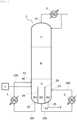
- FIG. 1 is a diagram illustrating a separation device and a process flow according to an embodiment
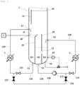
- FIG. 2 is a diagram illustrating a detailed structure of a bottom area A of a distillation column according to an embodiment.
- the separation device includes a distillation column 2, a first reboiler 3, a second reboiler 4, and a condenser 5.
- the distillation column 2 is a device that may separate multi-component substances contained in raw materials based on a difference in boiling points, respectively. Considering the boiling points of the inflowing raw material components, the components to be separated etc., a distillation column equipped with various types of trays 30 may be used in the separation device of the present disclosure. Furthermore, after an oligomerization process of an ethylene monomer, in order to minimize the risk of plugging due to by-products such as polymers while efficiently separating and recovering oligomer products and unreacted ethylene monomer contained in the reactor effluent discharged from the reactor 1, a distillation column equipped with double separation walls 10 and 20 at a bottom area A of the distillation column may be used in the separation device of the present disclosure.
- an inside of the distillation column 2 may be partitioned into a bottom area A, a middle area B, and a top area C.
- bottom area A refers to a relatively lower portion in the structure of the distillation column 2, and may refer to, for example, the lowermost portion of three areas partitioned in a height direction of the distillation column, and more specifically, an area under the lowermost tray, that is, the lower area.
- top area C refers to the relatively upper portion in the structure of the distillation column 2, and may refer to, for example, an uppermost portion of three areas partitioned in the height direction of the distillation column, and more specifically, an area over the uppermost tray, that is, the upper area.
- “middle area B” refers to the relatively middle part in the structure of the distillation column 2, and may refer to, for example, a middle area among three areas partitioned in the height direction of the distillation column, and more specifically, an area between the bottom area and top area of the distillation column, that is, an area between the lowermost tray and the uppermost tray.
- the bottom area A of the distillation column 2 is provided with a first separation wall 10, a second separation wall 20, a raw material supply port 40, a first outlet 51, a first reflux inlet 61, a second outlet 53, and a second reflux inlet 63, and may be further provided with a third outlet 55 and/or a third reflux inlet 65.
- the separation device may minimize the risk of plugging inside a column due to polymer by-products contained in the reactor effluent by providing the raw material supply port 40 in the bottom area A, and recover the entire amount of unreacted ethylene monomer to the reactor 1 without being lost to the bottom by changing a structure of a sump of the distillation column 2 using a double separation wall.
- the bottom area A of the distillation column 2 is provided with the double separation walls 10 and 20 in the sump where the liquid reactor effluent is collected.
- the sump may refer to an area where a solution is collected at a lower portion of the distillation column.
- the bottom area A may be partitioned into a liquid area and a gas phase area based on a liquid surface of a solution.
- the bottom area A of the distillation column 2 has a first area D1, a second area D2, and a third area D3 partitioned by a first separation wall 10 and a second separation wall 20 that extend from the bottom of the distillation column 2 to a predetermined height and are spaced apart from each other.
- the first area D1 and the second area D2 are partitioned with the first separation wall 10 therebetween, and the second area D2 and the third area D3 may be partitioned by a second separation wall 20 provided therebetween.
- the second area D2 may be located between the first separation wall 10 and the second separation wall 20.
- it is preferable that the first area D1, the second area D2, and the third area D3 partitioned by the first separation wall 10 and the second separation wall 20 are partitioned equally.
- the height of the first separation wall 10 and the second separation wall 20 may be appropriately changed depending on the structure or size of the distillation column. However, as illustrated in FIG. 1 , it may be provided so as not to contact the lowermost tray among the plurality of trays 30, which will be described later.
- the predetermined height may refer to a height at which the first separation wall 10 and/or the second separation wall 20 are spaced apart so as not contact the lowermost tray.
- first separation wall 10 and the second separation wall 20 are provided so as not to contact the lowermost tray among the plurality of trays 30 to be described later, so gas in a gas phase area of the bottom area A may be able to move between the first area D1, the second area D2, and the third area D3.
- an auxiliary tray 11 having a predetermined slope in a direction of the second area D2 may be further provided at an upper end of the first separation wall 10.
- the auxiliary tray 11 is provided to compensate for the phenomenon in which the solution injected into the first area D1 does not pass through the first reboiler 3 but is bypassed to the second area D2.
- the auxiliary tray 11 is inclined at an angle of less than 90°, more specifically about 40° to about 80°, in the direction of the second area D2 with respect to the first separation wall 10, but is not limited thereto.
- the overall height including the auxiliary tray may be the same as the height of the second separation wall 20, but is not limited thereto.
- one area of the second separation wall 20 may be provided with an opening 21.
- the opening 21 is located below the liquid surface of the solution in the second area D2 and the third area D3 to allow the solution to flow from the third area D3 to the second area D2, so the level of the solution inside two areas may be maintained the same.
- the shape and/or size of the opening 21 may be applied without particular limitation as long as it allows the solution to flow from the third area D3 to the second area D2.
- the opening 21 may include one or more holes, and may also include a plurality of holes having different diameters.
- the shape, size, and/or number of the holes are not particularly limited as long as the level of the solution inside the second area D2 and the third area D3 may be maintained the same.
- the raw material supply port 40, the first outlet 51, and the first reflux inlet 61 are provided in the first area D1 of the separation device according to one embodiment.
- the raw material supply port 40 is connected to the reactor 1 and provided on one side of the first area D1, so the reactor effluent containing the ethylene monomer and oligomer discharged from the reactor 1 may be supplied to the first area D1. More specifically, the raw material supply port 40 may be located on the side of the first area D1 of the distillation column 2 to have a height adjacent to the height of the first separation wall 10, and is preferably provided at a height higher than the liquid surface of the solution in the first area D1.
- the reactor effluent includes an oligomer product (alpha-olefin, P) produced by the oligomerization reaction of the ethylene monomer performed in the reactor 1 and the ethylene as the unreacted monomer, and may further include a polymer as a by-product.
- P alpha-olefin
- the raw material supply port 40 is located in the bottom area A to prevent the column plugging phenomenon.
- the oligomerization reaction may refer to a reaction in which a monomer is polymerized. Depending on the number of monomers to be polymerized, trimerization and tetramerization are called, and these trimerization and tetramerization are collectively called multimerization.
- Alpha-olefin is widely used commercially as an important material used as a comonomer, a detergent, a lubricant, a plasticizer, or the like.
- 1-hexene and 1-octene has been widely used as a comonomer for controlling a density of polyethylene in a production of linear low-density polyethylene (LLDPE).
- LLDPE linear low-density polyethylene
- the alpha-olefins such as 1-hexene and 1-octene may be produced, for example, through trimerization or tetramerization of ethylene.
- the first outlet 51 may be provided at the bottom of the lower portion of the first area D1 and connected to one side of the first reboiler 3 by a first flow path 110.
- a lower discharge stream of the first area D1 containing the reactor effluent, that is, the first stream, may be transferred to the first reboiler 3 through the first outlet 51 to perform primary heat exchange. Since both the reactor effluent containing the unreacted monomers and the dropping liquid from the lowermost tray flow into the first area D1, a flow rate of about 80 vol% or more, and preferably about 90 vol% or more, may be discharged through the first outlet 51 located at the lower portion of the first area D1 and induced to pass through the first reboiler 3.
- the first flow path 110 may be further provided with a valve 111 that can be opened and closed as needed.
- the reboilers 3 and 4 are heating devices separately installed outside the distillation column 2, and may refer to a device for reheating and evaporating the flow of high boiling point components discharged from the bottom of the distillation column.
- the first reboiler 3 may be a device that heats the first stream discharged from the lower portion of the first area D1 of the distillation column 2 through the first flow path 110 by primary heat exchange.
- a thermosyphon reboiler it may be preferable to use a thermosyphon reboiler as the first reboiler 3.
- thermosyphon reboiler is operated by a method of continuously supplying liquid at a lower portion of a distillation column to a reboiler with no power without a pump, and may be designed in which heat is supplied in the form of two phases of gas and liquid due to gas evaporating from the reboiler and a density is greatly reduced compared to the liquid at an inlet due to the gas, and thus, the natural circulation of the liquid continues to be performed stably due to the density difference and the liquid head pressure inside the distillation column.
- thermosyphon recirculation system that can be installed and operated at low cost, there is an advantage in that a large amount of circulation flow can be operated economically and efficiently without additional devices such as a pump.
- FIG. 3 illustrates a conventional separation device without a separation wall in the distillation column sump as a comparative example.
- FIG. 4 when the reactor effluent is injected into the bottom area where the separation wall is not provided, the areas of the liquid stream discharged to the reboiler and the liquid stream where the product is discharged are not separated. Accordingly, there is a problem in that the entire amount of reactor effluent does not pass through the reboiler, and the unreacted monomers along with the products may be discharged directly to the bottom.
- the separation device in the separation device according to an embodiment of the present disclosure, all the solution discharged from the reactor 1, a two-phase fluid that passes through the first reboiler 3, and the liquid separated and dropped after heat exchange in the column lowermost tray 30 flows into the first area D1 and overflow by at a flow rate that exceeds the amount discharged to the lower portion of the first area D1 and pass into the second area D2.
- the lower discharge stream (first stream) of the first area D1 performs the primary heat exchange through the thermosyphon recirculation system of the first reboiler 3.
- about 80 vol% or more and preferably 90 vol% or more of the total flow rate may be circulated to the first reboiler 3.
- the lower discharge stream (first stream) of the first area D1 may be heated to a temperature of about 200°C to 205°C by the primary heat exchange in the first reboiler 3.
- the first reflux inlet 61 is located in the upper portion of the first area D1, and may be connected to the other side of the first reboiler 3 by the second flow path 120 and provided on the side portion of the distillation column 2.
- the first stream that has passed through the first reboiler 3 through the first reflux inlet 61 may be refluxed back to the first area D1.
- the first reflux inlet 61 may be located at a height between the lowermost tray of the plurality of trays 30, which will be described later, and the raw material supply port 40.
- the solution in the first area D1 passes into the first separation wall 10 and is moved to the second area D2.
- the first reflux inlet 61 since the first reflux inlet 61 is located at a higher height than the raw material supply port 40, the solution of the first heat-exchanged first stream refluxed through the first reflux inlet 61 preferentially passes into the second area D2.
- the second outlet 53 is provided in the second area D2 and the second reflux inlet 63 is provided in the third area D3.
- the third outlet 55 and/or the third reflux inlet 65 may be additionally provided in the third area D3.
- the second outlet 53 may be provided at the bottom of the lower portion of the second area D2 located between the first separation wall 10 and the second separation wall 20, and connected to one side of the second reboiler 4 by the third flow path 130.
- the secondary heat exchange may be performed by transferring the lower discharge stream of the second area D2, that is, the second stream, to the second reboiler 4 through the second outlet 53.
- the third flow path 130 may be further provided with the valve 131 that can be opened and closed and/or the pump 133 as needed.
- the second reboiler 4 may be a device that heats the second stream flowing out through the third flow path 130 from the lower portion of the second area D2 of the distillation column 2.
- the second reboiler may be preferably a forced circulation reboiler.
- the forced circulation reboiler uses the pump 133 to forcibly supply liquid to the reboiler, and may be used for when the forced circulation is required, such as a fluid with high viscosity or when the fluid is sensitive to temperature and requires rapid reboiler circulation.
- the forced circulation reboiler When the forced circulation reboiler is used in the reboiler circulation in the second area D2, in the case where the efficiency of the thermosyphon reboiler in the first area D1 decreases over time due to the influence of high viscosity of the polymer solution, etc., as the flow rate of the first stream discharged to the first outlet 51 decreases, the heat exchange capacity in the first reboiler 3 decreases, so the reflux flow rate of the entire distillation column may also decrease.
- the second reboiler 4 compensates for the decrease in efficiency of the first reboiler 3, so the second boiler 4 can be operated for a long period of time.
- the lower discharge stream (second stream) of the second area D2 may be heated to a temperature of about 205°C to 210°C by the secondary heat exchange in the second reboiler 4.
- the unreacted ethylene monomer remaining in the solution may be converted into the vapor phase and the plugging phenomenon due to the polymer by-products may be prevented.
- the second reflux inlet 63 is provided in one side of the third area D3, and may be connected to the other side of the second reboiler 4 by the fourth flow path 140 and provided on the side portion of the distillation column 2.
- the second stream that has passed through the second reboiler 4 through the second reflux inlet 63 may be refluxed to the third area D3. More specifically, the second reflux inlet 63 may be located at a height between the upper end of the second separation wall 20 and the liquid surface of the solution in the third area D3.
- the liquid flowing into the second area D2 in excess of the capacity that may be accommodated in the first area D1 may flow beyond the first separation wall 10.
- the second stream is discharged to the second outlet 53 at the lower portion of the second area D2, passes through the second reboiler 4, and then recirculated through the second reflux inlet 63 may flow into the third area D3, and some of the solution in the third area D3 may flow back into the second area D2 through the opening 21 provided in the second separation wall 20.
- the solution level inside the second area D2 and the third area D3 may be maintained the same.
- the average temperature of the solution in the second area D2 may increase due to the solution flowing from the third area D3, so the third flow path 130 through which the second stream, which is the lower discharge stream of the second area D2, passes, may prevent the problem of the pipe plugging due to the polymer by-products.
- the bottom area A of the distillation column 2 is partitioned into a lower stream area of the first area D1 that discharges the reactor effluent to the first reboiler 3, a lower stream area of the second area D2 that discharges the solution overflowing from the primary heat-exchanged liquid stream passing through the first reboiler 3 to the second reboiler 4, and a lower stream area of third area D3 discharging a product P by the first separation wall 10 and the second separation wall 20, and the raw material supply port 40 is located in the first area D1, so the flow rate of about 80 vol% or more of the reactor effluent, preferably about 90 vol% of the reactor effluent is designed to pass through the first reboiler 3, thereby further improving the separation efficiency of the unreacted monomers.
- the reactor effluent feed is directly injected into the sump of the distillation column, so some of the unreacted ethylene monomer dissolved in the solution is still included in the solution and may not be separated into vapor and may pass into the second area D2.
- the lower discharge stream (second stream) of the second area D2 also performs secondary heat exchange through the forced circulation system of the second reboiler 4 to achieve the role of the first stage of a complete distillation column that separates unreacted ethylene monomer into a gas phase.
- the entire amount of ethylene monomer, which is the unreacted reaction raw material may be recovered to the upper portion of the distillation column, that is, to the top, without the plugging (fouling) of the structure in the column, making it possible to operate a stable and economical separation process.
- the flow rate ratio of the first stream flowing out through the first flow path 110 and the second stream flowing out through the third flow path 130 may be 7:3 to 9:1, and is preferably about 7.5:2.5 to 8.5:1.5.
- the sum of the heat amount of the first stream that flows out through the first flow path 110 and passes through the first reboiler 3 and the second stream that flows out through the third flow path 130 and passes through the second reboiler 4 may be maintained the same. Since the amount of heat required throughout the separation process is fixed, even if two reboilers are used as in the present disclosure, the total heat amount may be the same as the conventional separation process using one reboiler. More specifically, by using different types of reboilers with different flow rates together, it may function as the complete first stage of the column.
- the average temperature of the solution (i.e., liquid area) in the bottom area A of the distillation column 2 may range from about 195°C to 210°C, and preferably from about 200°C to 205°C.
- appropriate heat exchange may be achieved by the first reboiler and the second reboiler, and an appropriate steam generation rate at the rear end of the reboiler may be maintained.
- the average temperature of the solution in the second area D2 may be relatively higher than that of the solution in the first area D1
- the average temperature of the solution in the third area D3 may be relatively higher than that of the solution in the second area D2.
- the average temperature of the solution in the first area D1 of the distillation column 2 may range from about 195°C to 200°C
- the average temperature of the solution in the second area D2 may range from about 200°C to 205°C
- the average temperature of the solution in the third area D3 may range from about 205°C to about 210°C.
- the difference in the average temperature of the solution in the first area D1 and the solution in the second area D2 may be about 5°C to 10°C
- the difference in the average temperature of the solution in the second area D2 and the solution in the third area D3 may be about 2°C to 5°C.
- the flowability of the solution contained in the relatively high-temperature third area D3 to the relative low-temperature second area D2 through the opening 21 may be improved.
- the effect of the temperature of the solution in the third area D3 being refluxed through the second reboiler 4 being transferred to the second area D2 through the opening 21 may be achieved.
- the relatively high-temperature fluid present in the third area D3 moves to the second area D2 where the relatively low-temperature fluid exists and is mixed to increase the temperature of the liquid stream introduced into the second reboiler 4, thereby preventing the plugging of the pipe (i.e., the third flow path) by the polymer by-products in the stream.
- the separation device may further include a preliminary flow path 150 connecting the first flow path 110 and the third flow path 130.
- the preliminary flow path 150 may be further provided with one or more valves 151 and 152 that can be opened and closed, and the first flow path 110 and/or the third flow path 130 may also be provided with one or more valves 111 and 131 that can be opened and closed, respectively.
- valves 151 and 152 of the preliminary flow path may be closed.
- valves 151 and 152 of the preliminary flow path may be opened.
- valves 151 and 152 of the preliminary flow path may be opened.
- the valve 111 provided in the first flow path 110 may be closed.
- the first reboiler 3 with a larger capacity may be converted into the forced circulation form by the pump 133 of the third flow path, and the second boiler 4 may also be used in a modified form that does not operate.
- the solution in the first area D1 has a relatively low average temperature, there is a possibility that the pipe plugging problem in the first flow path 110 may occur due to the polymer by-products in the first stream.
- the efficiency of the thermosiphon reboiler which is the first reboiler 3
- the circulation flow rate increases through the mechanical stroke control of the forced circulation pump 133 and the decrease in efficiency of the first reboiler 3 is compensated by adding the supply of steam heat from the second reboiler 4, thereby overcoming the problem due to the decrease in efficiency of the first reboiler 3.
- the third outlet 55 is provided at the bottom of the lower portion of the third area D3 of the distillation column 2.
- the third stream containing the oligomer product P may be discharged through the third outlet 55.
- the third reflux inlet 65 may be connected to the third outlet 55, located below the liquid surface of the solution in the third area D3, and provided on the side portion of the distillation column 2. More specifically, some of the liquid stream P containing the oligomer discharged to the third outlet 55 is recovered, and the remaining of the stream may be branched and refluxed back to the third area (D3) through the third reflux inlet 65.
- FIG. 3 illustrating the conventional separation device using the distillation column without the separation wall in the sump
- the reactor effluent is injected into the bottom area without the separation wall
- the areas of the stream discharged from the reboiler and the stream discharged from the product are not separated, so the entire reactor effluent does not pass through the reboiler (heat exchanger).
- the reboiler heat exchanger
- the bottom area A of the distillation column 2 is partitioned into the first area D1 in which the bottom area A of the distillation column 2 is provided with the first outlet 51 through which the reactor effluent is discharged to the first reboiler 3, the second area D2 provided with the second outlet 53 through which the solution overflowing from the first area D1 is discharged to the second reboiler 4, and the third area D3 provided with the third outlet 55 through which an oligomer product P with a relatively high boiling point is discharged by the first separation wall 10 and the second separation wall 20, and the raw material supply port 40 is located on the first area D1, so the entire reactor effluent is designed to necessarily pass through the first reboiler 3 and/or the second reboiler 4, thereby maximizing the separation efficiency of the unreacted monomers.
- the middle area B of the distillation column 2 includes the plurality of trays 30.
- the plurality of trays 30 are arranged in a vertical direction of the double separation walls 10 and 20 and are spaced apart from each other.
- the gaseous stream containing the unreacted monomer gas generated in the bottom area A passes through the plurality of trays 30 provided in the middle area B, is separated into gas and liquid, and moves to the top area C which will be described later.
- the number and type of the plurality of trays 30 may be appropriately selected in consideration of the type of distillation column 2 and the desired separation efficiency, and the type of tray may be used without particularly limited as long as it is a tray normally used in a distillation column for gas-liquid separation.
- the distillation column 2 may be a distillation column with 10 to 30 theoretical stages.
- “theoretical stages” refers to the number of stages partitioned by a virtual area or a plurality of trays in the distillation column 2 where two phases, such as gas phase and liquid phase, are in equilibrium with each other.
- one end of the lowermost tray 30 among the plurality of trays is located in the upper portion of the first area D1, and the separation device may further include a guide partition wall 31 extending downward from one end of the lowermost tray 30.
- One end of the lowermost tray 30 may be open so as not to contact the side portion of the distillation column 2 on the first area D1.
- the dropping liquid separated from the lowermost tray 30 after contact with gas and liquid may be guided to the first area D1 through the guide partition wall 31. Since the unreacted ethylene monomer may be dissolved even in the solution (dropping liquid) dropping from the tray, the guide partition wall 31 is provided at the end of the lowermost tray to ensure that the solution dropping from the tray flows only into the first area D1 to prevent the product from being lost directly to the third outlet 55, which is the product P outlet, without passing through the first reboiler 3 and/or the second reboiler 4, thereby maximizing the recovery rate of the unreacted monomers.
- a fourth outlet 57 connected to the condenser 5 is provided at the upper portion of the top area C of the distillation column 2.
- the condenser 5 is a device that is separately installed outside the distillation column 2, and refers to a device for cooling the flow discharged from the top of the distillation column by contacting it with cooling water flowing from the outside.
- the condenser 5 may be a device that condenses the gaseous stream discharged upward from the top area C of the distillation column 2 through the fourth outlet 57.
- the gaseous stream containing the unreacted ethylene monomer may pass through the plurality of trays 30 in the middle area B, reach the top area C of the distillation column 2, and then discharged to the condenser 5 through the fourth outlet 57 as an upper gaseous stream.
- the upper gaseous stream discharged from the condenser 5 may be condensed and return to the reactor 1.
- some of the condensed top stream may be partitioned and recycled to the distillation column 2, but is not limited thereto.
Landscapes
- Chemical & Material Sciences (AREA)
- Organic Chemistry (AREA)
- Chemical Kinetics & Catalysis (AREA)
- Engineering & Computer Science (AREA)
- Analytical Chemistry (AREA)
- Oil, Petroleum & Natural Gas (AREA)
- Water Supply & Treatment (AREA)
- Vaporization, Distillation, Condensation, Sublimation, And Cold Traps (AREA)
Abstract
Description
- This application claims priority to and the benefit of
Korean Patent Application No. 10-2023-0103230 filed on August 08, 2023 - The present disclosure relates to a separation device used in an oligomerization process using an ethylene monomer, and more particularly, to a separation device capable of preventing plugging problems due to polymer by-products and improving a recovery rate of unreacted ethylene by changing an inside of a sump of a distillation column to a double separation wall structure and improving a circulation system.
- Alpha-olefin is widely used commercially as an important material used as a comonomer, a detergent, a lubricant, a plasticizer, or the like. In particular, 1-hexene and 1-octene has been widely used as a comonomer for controlling a density of polyethylene in a production of linear low-density polyethylene (LLDPE).
- The alpha-olefin is typically prepared through the oligomerization reaction of ethylene, and a polymer is produced as a by-product during this preparation process. The polymer produced by a side reaction is contained in reactor effluents in an amount of about 1% by weight or less and is injected into the distillation column in a post-process. In this case, when the reactor emissions are directly injected into a feed stage tray, there is a very high risk of plugging phenomenon due to by-products such as polymers. Accordingly, a method of directly injecting reactor effluents into a reboiler section has been considered.
- However, the reactor effluent contains an unreacted ethylene monomer in addition to by-products, and when the feed stage becomes the reboiler section, the separation efficiency of the unreacted ethylene monomer is greatly reduced. Accordingly, there is a problem that the entire amount of unreacted ethylene monomer may not be recovered from the reactor, and some of the unreacted ethylene monomer is leaked along with a bottom (BTM) product, and such loss of raw materials also causes financial loss.
- Therefore, in order to solve the above problems, research is needed to prevent the plugging phenomenon due to polymer by-products in the separation process after the ethylene reaction in a post-process, and at the same time, minimize the loss of the unreacted ethylene monomer.
- The problem to be solved by the present disclosure is to solve the problems mentioned in the Background Technology of the above disclosure, and an object of the present disclosure provides a separation device capable of preventing a plugging phenomenon due to polymer by-products in a post-process of an oligomerization reaction process, and at the same time, recovering an unreacted ethylene monomer without being lost to the lower portion of the distillation column by improving a sump structure at a lower portion of a distillation column and a circulation system.
- However, problems to be solved by the present disclosure are not limited to the above-mentioned aspects. That is, other aspects that are not described may be obviously understood by those skilled in the art from the following description.
- To solve the above problem, according to an embodiment of the present disclosure, a separation device includes a distillation column having a double separation wall, a first reboiler, a second reboiler, and a condenser. An inside of the distillation column may be partitioned into a bottom area, a middle area; and a top area.
- The bottom area of the distillation column may include first to third areas that are partitioned by a first separation wall and a second separation wall extending from a bottom of the distillation column to a predetermined height and spaced apart from each other, a raw material supply port that is provided at one side of the first area and has a reactor effluent containing a monomer and an oligomer to the first area transferred therethrough, a first outlet that is provided at a lower portion of the first area and connected to one side of the first reboiler by a first flow path, a first reflux inlet that is provided at an upper portion of the first area and connected to the other side of the first reboiler by a second flow path, a second outlet that is provided at a lower portion of the second area located between the first dividing wall and the second dividing wall, and connected to one side of the second reboiler by a third flow path, and a second reflux inlet that is provided on one side of the third area and connected to the other side of the second reboiler by a fourth flow path.
- According to the separation device of the present disclosure, by improving the structure of the distillation column sump and the circulation system, it is possible to minimize the risk of plugging (fouling) of the internal structure of the column that may occur due to the polymer by-products contained in the reactor effluent and recover the entire amount of unreacted monomer dissolved in the solution to the reactor without being lost to the lower portion.
- More specifically, by providing the double separation wall at the lower portion of the distillation column to divide the sump into a total of 3 areas and by using two reboilers with different flow rates, it is possible to function as a complete first stage of the column.
- Effects which can be achieved by the present disclosure are not limited to the above-described effects. That is, other effects that are not described may be obviously understood by those skilled in the art to which the present disclosure pertains from the following description.
-
-
FIG. 1 is a process diagram of a separation device according to an embodiment. -
FIG. 2 is a diagram illustrating in detail a structure of a bottom area of a distillation column in the separation device according to the embodiment. -
FIG. 3 is a diagram illustrating a conventional separation system as Comparative Example. - Terms and words used in the present specification and claims are not to be construed as a general or dictionary meaning but are to be construed as meaning and concepts meeting the technical ideas of the present disclosure based on a principle that the inventors can appropriately define the concepts of terms in order to describe their own disclosures in best mode.
- Throughout the accompanying drawings, similar or related components will be denoted by similar reference numerals.
- A singular form of a noun corresponding to an item may include one or more of the items, unless the relevant context clearly dictates otherwise.
- In the present disclosure, each phrase such as "A or B," "at least one of A and B," "at least one of A or B," "A, B, or C," "at least one of A, B and C," and "at least one of A, B, or C" may include any one of items listed together in the corresponding one of those phrases, or all possible combinations thereof.
- The term "and/or" includes a combination of a plurality of related described components or any one of the pluralities of related described components.
- Terms such as "first," "second," "1st," or "2nd" may simply be used to distinguish a component from another component, and do not limit the components in other respects (e.g., importance or order).
- In addition, the terms such as 'front', 'rear', 'top', 'bottom', 'side', 'left', 'right', 'upper', 'lower', etc., used herein are defined based on the drawings, the shape and location of each component are not limited by this term.
- It will be understood that terms 'include' or 'have' used in the present disclosure, specify the presence of features, numerals, steps, operations, components, parts mentioned in the present specification, or a combination thereof, but do not preclude the presence or addition of one or more other features, numerals, steps, operations, components, parts, or a combination thereof.
- When a component is "connected," "coupled," "supported," or "contacted" with another component, this includes not only cases where the components are directly connected, coupled, supported, or contacted, but also cases where the components are indirectly connected, coupled, supported or contacted through a third component.
- When a component is located "on" another component, this includes not only cases where a component is in contact with another component, but also cases where another component exists between the two components.
- The terms "about," "substantially," or the like used throughout the present specification means figures corresponding to manufacturing and material tolerances specific to the stated meaning and figures close thereto, and are used to prevent unconscionable abusers from unfairly using the disclosure of figures precisely or absolutely described to aid the understanding of the present disclosure.
- The term 'stream' used herein may mean a flow of a fluid in a process, and may also mean a fluid itself flowing in a pipe. Specifically, the stream may mean both the fluid itself and the flow of the fluid flowing within the pipe connecting each device. In addition, the fluid may include any at least one components of a gas, a liquid, and a solid.
- Hereinafter, a separation device of the present disclosure will be described with reference to the attached drawings, but the attached drawings are exemplary, and the scope of the separation device is not limited thereto.
-
FIG. 1 is a diagram illustrating a separation device and a process flow according to an embodiment, andFIG. 2 is a diagram illustrating a detailed structure of a bottom area A of a distillation column according to an embodiment. - Referring to
FIG. 1 , the separation device according to an embodiment of the present disclosure includes adistillation column 2, afirst reboiler 3, asecond reboiler 4, and acondenser 5. - The
distillation column 2 is a device that may separate multi-component substances contained in raw materials based on a difference in boiling points, respectively. Considering the boiling points of the inflowing raw material components, the components to be separated etc., a distillation column equipped with various types oftrays 30 may be used in the separation device of the present disclosure. Furthermore, after an oligomerization process of an ethylene monomer, in order to minimize the risk of plugging due to by-products such as polymers while efficiently separating and recovering oligomer products and unreacted ethylene monomer contained in the reactor effluent discharged from thereactor 1, a distillation column equipped withdouble separation walls - For example, as illustrated in
FIG. 1 , an inside of thedistillation column 2 may be partitioned into a bottom area A, a middle area B, and a top area C. - In this specification, the term "bottom area A" refers to a relatively lower portion in the structure of the
distillation column 2, and may refer to, for example, the lowermost portion of three areas partitioned in a height direction of the distillation column, and more specifically, an area under the lowermost tray, that is, the lower area. - In this specification, the term "top area C" refers to the relatively upper portion in the structure of the
distillation column 2, and may refer to, for example, an uppermost portion of three areas partitioned in the height direction of the distillation column, and more specifically, an area over the uppermost tray, that is, the upper area. - In addition, in this specification, "middle area B" refers to the relatively middle part in the structure of the
distillation column 2, and may refer to, for example, a middle area among three areas partitioned in the height direction of the distillation column, and more specifically, an area between the bottom area and top area of the distillation column, that is, an area between the lowermost tray and the uppermost tray. - In one embodiment, the bottom area A of the
distillation column 2 is provided with afirst separation wall 10, asecond separation wall 20, a rawmaterial supply port 40, afirst outlet 51, afirst reflux inlet 61, asecond outlet 53, and asecond reflux inlet 63, and may be further provided with athird outlet 55 and/or athird reflux inlet 65. - The separation device according to one embodiment may minimize the risk of plugging inside a column due to polymer by-products contained in the reactor effluent by providing the raw
material supply port 40 in the bottom area A, and recover the entire amount of unreacted ethylene monomer to thereactor 1 without being lost to the bottom by changing a structure of a sump of thedistillation column 2 using a double separation wall. - In one embodiment, the bottom area A of the
distillation column 2 is provided with thedouble separation walls - More specifically, referring to
FIG. 1 , the bottom area A of thedistillation column 2 has a first area D1, a second area D2, and a third area D3 partitioned by afirst separation wall 10 and asecond separation wall 20 that extend from the bottom of thedistillation column 2 to a predetermined height and are spaced apart from each other. For example, the first area D1 and the second area D2 are partitioned with thefirst separation wall 10 therebetween, and the second area D2 and the third area D3 may be partitioned by asecond separation wall 20 provided therebetween. In addition, the second area D2 may be located between thefirst separation wall 10 and thesecond separation wall 20. Furthermore, it is preferable that the first area D1, the second area D2, and the third area D3 partitioned by thefirst separation wall 10 and thesecond separation wall 20 are partitioned equally. - Meanwhile, the height of the
first separation wall 10 and thesecond separation wall 20 may be appropriately changed depending on the structure or size of the distillation column. However, as illustrated inFIG. 1 , it may be provided so as not to contact the lowermost tray among the plurality oftrays 30, which will be described later. Here, the predetermined height may refer to a height at which thefirst separation wall 10 and/or thesecond separation wall 20 are spaced apart so as not contact the lowermost tray. For example, it may be preferable for thefirst separation wall 10 and thesecond separation wall 20 to have the same height, but the height is not limited thereto. - In addition, upper ends of the
first separation wall 10 and thesecond separation wall 20 are provided so as not to contact the lowermost tray among the plurality oftrays 30 to be described later, so gas in a gas phase area of the bottom area A may be able to move between the first area D1, the second area D2, and the third area D3. - Meanwhile, referring to
FIG. 2 , anauxiliary tray 11 having a predetermined slope in a direction of the second area D2 may be further provided at an upper end of thefirst separation wall 10. Theauxiliary tray 11 is provided to compensate for the phenomenon in which the solution injected into the first area D1 does not pass through thefirst reboiler 3 but is bypassed to the second area D2. For example, theauxiliary tray 11 is inclined at an angle of less than 90°, more specifically about 40° to about 80°, in the direction of the second area D2 with respect to thefirst separation wall 10, but is not limited thereto. In addition, when thefirst separation wall 10 is provided with theauxiliary tray 11, the overall height including the auxiliary tray may be the same as the height of thesecond separation wall 20, but is not limited thereto. - In one embodiment, one area of the
second separation wall 20 may be provided with anopening 21. Referring toFIG. 2 , theopening 21 is located below the liquid surface of the solution in the second area D2 and the third area D3 to allow the solution to flow from the third area D3 to the second area D2, so the level of the solution inside two areas may be maintained the same. The shape and/or size of theopening 21 may be applied without particular limitation as long as it allows the solution to flow from the third area D3 to the second area D2. For example, theopening 21 may include one or more holes, and may also include a plurality of holes having different diameters. The shape, size, and/or number of the holes are not particularly limited as long as the level of the solution inside the second area D2 and the third area D3 may be maintained the same. - Referring to
FIG. 1 , the rawmaterial supply port 40, thefirst outlet 51, and thefirst reflux inlet 61 are provided in the first area D1 of the separation device according to one embodiment. - In one embodiment, the raw
material supply port 40 is connected to thereactor 1 and provided on one side of the first area D1, so the reactor effluent containing the ethylene monomer and oligomer discharged from thereactor 1 may be supplied to the first area D1. More specifically, the rawmaterial supply port 40 may be located on the side of the first area D1 of thedistillation column 2 to have a height adjacent to the height of thefirst separation wall 10, and is preferably provided at a height higher than the liquid surface of the solution in the first area D1. - Here, the reactor effluent includes an oligomer product (alpha-olefin, P) produced by the oligomerization reaction of the ethylene monomer performed in the
reactor 1 and the ethylene as the unreacted monomer, and may further include a polymer as a by-product. As in the related art, when the reactor effluent is injected into the feed stage tray located in the middle area of the column, there is the risk of plugging phenomenon due to the polymer by-product. However, in the present disclosure, the rawmaterial supply port 40 is located in the bottom area A to prevent the column plugging phenomenon. - The oligomerization reaction may refer to a reaction in which a monomer is polymerized. Depending on the number of monomers to be polymerized, trimerization and tetramerization are called, and these trimerization and tetramerization are collectively called multimerization. Alpha-olefin is widely used commercially as an important material used as a comonomer, a detergent, a lubricant, a plasticizer, or the like. In particular, 1-hexene and 1-octene has been widely used as a comonomer for controlling a density of polyethylene in a production of linear low-density polyethylene (LLDPE). The alpha-olefins such as 1-hexene and 1-octene may be produced, for example, through trimerization or tetramerization of ethylene.
- Meanwhile, in one embodiment, the
first outlet 51 may be provided at the bottom of the lower portion of the first area D1 and connected to one side of thefirst reboiler 3 by afirst flow path 110. A lower discharge stream of the first area D1 containing the reactor effluent, that is, the first stream, may be transferred to thefirst reboiler 3 through thefirst outlet 51 to perform primary heat exchange. Since both the reactor effluent containing the unreacted monomers and the dropping liquid from the lowermost tray flow into the first area D1, a flow rate of about 80 vol% or more, and preferably about 90 vol% or more, may be discharged through thefirst outlet 51 located at the lower portion of the first area D1 and induced to pass through thefirst reboiler 3. - In addition, as illustrated in
FIG. 2 , thefirst flow path 110 may be further provided with avalve 111 that can be opened and closed as needed. - In the present application, the
reboilers distillation column 2, and may refer to a device for reheating and evaporating the flow of high boiling point components discharged from the bottom of the distillation column. - In one embodiment, the
first reboiler 3 may be a device that heats the first stream discharged from the lower portion of the first area D1 of thedistillation column 2 through thefirst flow path 110 by primary heat exchange. For example, it may be preferable to use a thermosyphon reboiler as thefirst reboiler 3. The thermosyphon reboiler is operated by a method of continuously supplying liquid at a lower portion of a distillation column to a reboiler with no power without a pump, and may be designed in which heat is supplied in the form of two phases of gas and liquid due to gas evaporating from the reboiler and a density is greatly reduced compared to the liquid at an inlet due to the gas, and thus, the natural circulation of the liquid continues to be performed stably due to the density difference and the liquid head pressure inside the distillation column. There may be a certain percentage of polymer by-products in the sump of the distillation column, but it is determined that the amount of the polymer by-products is not only extremely small, but the polymer by-products are in a liquefied state under high temperature conditions. Therefore, by performing the primary heat exchange through the thermosyphon recirculation system that can be installed and operated at low cost, there is an advantage in that a large amount of circulation flow can be operated economically and efficiently without additional devices such as a pump. - Meanwhile,
FIG. 3 illustrates a conventional separation device without a separation wall in the distillation column sump as a comparative example. As illustrated in FIG. 4, when the reactor effluent is injected into the bottom area where the separation wall is not provided, the areas of the liquid stream discharged to the reboiler and the liquid stream where the product is discharged are not separated. Accordingly, there is a problem in that the entire amount of reactor effluent does not pass through the reboiler, and the unreacted monomers along with the products may be discharged directly to the bottom. - On the other hand, as described above, in the separation device according to an embodiment of the present disclosure, all the solution discharged from the
reactor 1, a two-phase fluid that passes through thefirst reboiler 3, and the liquid separated and dropped after heat exchange in the columnlowermost tray 30 flows into the first area D1 and overflow by at a flow rate that exceeds the amount discharged to the lower portion of the first area D1 and pass into the second area D2. Here, the lower discharge stream (first stream) of the first area D1 performs the primary heat exchange through the thermosyphon recirculation system of thefirst reboiler 3. In this case, about 80 vol% or more and preferably 90 vol% or more of the total flow rate may be circulated to thefirst reboiler 3. As a result, there is the advantage of increasing the recovery rate of the unreacted ethylene monomer. - In addition, the lower discharge stream (first stream) of the first area D1 may be heated to a temperature of about 200°C to 205°C by the primary heat exchange in the
first reboiler 3. By heating the first stream to the above temperature range through the primary heat exchange, it is possible to prevent the pipe plugging phenomenon due to the polymer by-products while converting the unreacted ethylene monomer dissolved in the solution into the vapor phase. - In one embodiment, the
first reflux inlet 61 is located in the upper portion of the first area D1, and may be connected to the other side of thefirst reboiler 3 by thesecond flow path 120 and provided on the side portion of thedistillation column 2. The first stream that has passed through thefirst reboiler 3 through thefirst reflux inlet 61 may be refluxed back to the first area D1. - More specifically, the
first reflux inlet 61 may be located at a height between the lowermost tray of the plurality oftrays 30, which will be described later, and the rawmaterial supply port 40. The reactor effluent flowing from thereactor 1 through the rawmaterial supply port 40, the first stream discharged to thefirst outlet 51, passed through thefirst reboiler 3, and then recycled through thefirst reflux inlet 61, and/or the liquid separated and dropped from thelowermost tray 30, which will be described later, flow into the first area D1. In this way, when the flow rate flowing into the first area D1 exceeds the capacity that may be accommodated in the first area D1, the solution in the first area D1 passes into thefirst separation wall 10 and is moved to the second area D2. In this case, since thefirst reflux inlet 61 is located at a higher height than the rawmaterial supply port 40, the solution of the first heat-exchanged first stream refluxed through thefirst reflux inlet 61 preferentially passes into the second area D2. - Referring to
FIG. 1 , according to one embodiment, thesecond outlet 53 is provided in the second area D2 and thesecond reflux inlet 63 is provided in the third area D3. In addition, as illustrated inFIG. 2 , thethird outlet 55 and/or thethird reflux inlet 65 may be additionally provided in the third area D3. - In one embodiment, the
second outlet 53 may be provided at the bottom of the lower portion of the second area D2 located between thefirst separation wall 10 and thesecond separation wall 20, and connected to one side of thesecond reboiler 4 by thethird flow path 130. The secondary heat exchange may be performed by transferring the lower discharge stream of the second area D2, that is, the second stream, to thesecond reboiler 4 through thesecond outlet 53. In addition, as illustrated inFIG. 2 , thethird flow path 130 may be further provided with thevalve 131 that can be opened and closed and/or thepump 133 as needed. - The
second reboiler 4 may be a device that heats the second stream flowing out through thethird flow path 130 from the lower portion of the second area D2 of thedistillation column 2. For example, the second reboiler may be preferably a forced circulation reboiler. The forced circulation reboiler uses thepump 133 to forcibly supply liquid to the reboiler, and may be used for when the forced circulation is required, such as a fluid with high viscosity or when the fluid is sensitive to temperature and requires rapid reboiler circulation. When the forced circulation reboiler is used in the reboiler circulation in the second area D2, in the case where the efficiency of the thermosyphon reboiler in the first area D1 decreases over time due to the influence of high viscosity of the polymer solution, etc., as the flow rate of the first stream discharged to thefirst outlet 51 decreases, the heat exchange capacity in thefirst reboiler 3 decreases, so the reflux flow rate of the entire distillation column may also decrease. In this case, by adjusting the relative ratio of the circulation flow rates between thefirst reboiler 3 and thesecond reboiler 4, thesecond reboiler 4 compensates for the decrease in efficiency of thefirst reboiler 3, so thesecond boiler 4 can be operated for a long period of time. - In addition, the lower discharge stream (second stream) of the second area D2 may be heated to a temperature of about 205°C to 210°C by the secondary heat exchange in the
second reboiler 4. By heating to the above temperature range, the unreacted ethylene monomer remaining in the solution may be converted into the vapor phase and the plugging phenomenon due to the polymer by-products may be prevented. - In one embodiment, the
second reflux inlet 63 is provided in one side of the third area D3, and may be connected to the other side of thesecond reboiler 4 by thefourth flow path 140 and provided on the side portion of thedistillation column 2. The second stream that has passed through thesecond reboiler 4 through thesecond reflux inlet 63 may be refluxed to the third area D3. More specifically, thesecond reflux inlet 63 may be located at a height between the upper end of thesecond separation wall 20 and the liquid surface of the solution in the third area D3. - As described above, the liquid flowing into the second area D2 in excess of the capacity that may be accommodated in the first area D1 may flow beyond the
first separation wall 10. Furthermore, the second stream is discharged to thesecond outlet 53 at the lower portion of the second area D2, passes through thesecond reboiler 4, and then recirculated through thesecond reflux inlet 63 may flow into the third area D3, and some of the solution in the third area D3 may flow back into the second area D2 through theopening 21 provided in thesecond separation wall 20. As a result, the solution level inside the second area D2 and the third area D3 may be maintained the same. Furthermore, the average temperature of the solution in the second area D2 may increase due to the solution flowing from the third area D3, so thethird flow path 130 through which the second stream, which is the lower discharge stream of the second area D2, passes, may prevent the problem of the pipe plugging due to the polymer by-products. - In addition, the bottom area A of the
distillation column 2 is partitioned into a lower stream area of the first area D1 that discharges the reactor effluent to thefirst reboiler 3, a lower stream area of the second area D2 that discharges the solution overflowing from the primary heat-exchanged liquid stream passing through thefirst reboiler 3 to thesecond reboiler 4, and a lower stream area of third area D3 discharging a product P by thefirst separation wall 10 and thesecond separation wall 20, and the rawmaterial supply port 40 is located in the first area D1, so the flow rate of about 80 vol% or more of the reactor effluent, preferably about 90 vol% of the reactor effluent is designed to pass through thefirst reboiler 3, thereby further improving the separation efficiency of the unreacted monomers. - However, in the reaction device according to the present disclosure, in order to prevent the plugging of the structure in the column due to the polymer by-products contained in the reactor effluent, the reactor effluent feed is directly injected into the sump of the distillation column, so some of the unreacted ethylene monomer dissolved in the solution is still included in the solution and may not be separated into vapor and may pass into the second area D2. To compensate for this, the lower discharge stream (second stream) of the second area D2 also performs secondary heat exchange through the forced circulation system of the
second reboiler 4 to achieve the role of the first stage of a complete distillation column that separates unreacted ethylene monomer into a gas phase. Accordingly, ultimately, the entire amount of ethylene monomer, which is the unreacted reaction raw material, may be recovered to the upper portion of the distillation column, that is, to the top, without the plugging (fouling) of the structure in the column, making it possible to operate a stable and economical separation process. - Meanwhile, the flow rate ratio of the first stream flowing out through the
first flow path 110 and the second stream flowing out through thethird flow path 130 may be 7:3 to 9:1, and is preferably about 7.5:2.5 to 8.5:1.5. In this case, by satisfying the flow rate ratio, the sum of the heat amount of the first stream that flows out through thefirst flow path 110 and passes through thefirst reboiler 3 and the second stream that flows out through thethird flow path 130 and passes through thesecond reboiler 4 may be maintained the same. Since the amount of heat required throughout the separation process is fixed, even if two reboilers are used as in the present disclosure, the total heat amount may be the same as the conventional separation process using one reboiler. More specifically, by using different types of reboilers with different flow rates together, it may function as the complete first stage of the column. - Meanwhile, the average temperature of the solution (i.e., liquid area) in the bottom area A of the
distillation column 2 may range from about 195°C to 210°C, and preferably from about 200°C to 205°C. When the above temperature range is satisfied, appropriate heat exchange may be achieved by the first reboiler and the second reboiler, and an appropriate steam generation rate at the rear end of the reboiler may be maintained. - More specifically, the average temperature of the solution in the second area D2 may be relatively higher than that of the solution in the first area D1, and the average temperature of the solution in the third area D3 may be relatively higher than that of the solution in the second area D2. For example, the average temperature of the solution in the first area D1 of the
distillation column 2 may range from about 195°C to 200°C, the average temperature of the solution in the second area D2 may range from about 200°C to 205°C, and the average temperature of the solution in the third area D3 may range from about 205°C to about 210°C. When each area satisfies the above temperature range, appropriate separation of vapor dissolved in the solution and efficient operation of two reboilers may be possible. - More specifically, the difference in the average temperature of the solution in the first area D1 and the solution in the second area D2 may be about 5°C to 10°C, and the difference in the average temperature of the solution in the second area D2 and the solution in the third area D3 may be about 2°C to 5°C. In particular, due to the difference in the average temperature between the solution in the second area D2 and the solution in the third area D3, the flowability of the solution contained in the relatively high-temperature third area D3 to the relative low-temperature second area D2 through the
opening 21 may be improved. In addition, the effect of the temperature of the solution in the third area D3 being refluxed through thesecond reboiler 4 being transferred to the second area D2 through theopening 21 may be achieved. That is, the relatively high-temperature fluid present in the third area D3 moves to the second area D2 where the relatively low-temperature fluid exists and is mixed to increase the temperature of the liquid stream introduced into thesecond reboiler 4, thereby preventing the plugging of the pipe (i.e., the third flow path) by the polymer by-products in the stream. - Meanwhile, as illustrated in
FIG. 2 , the separation device according to one implementation may further include apreliminary flow path 150 connecting thefirst flow path 110 and thethird flow path 130. Furthermore, thepreliminary flow path 150 may be further provided with one ormore valves first flow path 110 and/or thethird flow path 130 may also be provided with one ormore valves - For example, when the
valve 131 of the third flow path is opened, thevalves valve 131 of the third flow path is closed, thevalves valves valve 111 provided in thefirst flow path 110 may be closed. Furthermore, through the opening and closing operation of thevalves first reboiler 3 with a larger capacity may be converted into the forced circulation form by thepump 133 of the third flow path, and thesecond boiler 4 may also be used in a modified form that does not operate. - As described above, since the solution in the first area D1 has a relatively low average temperature, there is a possibility that the pipe plugging problem in the
first flow path 110 may occur due to the polymer by-products in the first stream. In this way, when the efficiency of the thermosiphon reboiler, which is thefirst reboiler 3, decreases due to the accumulation of the polymer by-products, the circulation flow rate increases through the mechanical stroke control of the forcedcirculation pump 133 and the decrease in efficiency of thefirst reboiler 3 is compensated by adding the supply of steam heat from thesecond reboiler 4, thereby overcoming the problem due to the decrease in efficiency of thefirst reboiler 3. - In one embodiment, the
third outlet 55 is provided at the bottom of the lower portion of the third area D3 of thedistillation column 2. The third stream containing the oligomer product P may be discharged through thethird outlet 55. Referring toFIG. 2 , thethird reflux inlet 65 may be connected to thethird outlet 55, located below the liquid surface of the solution in the third area D3, and provided on the side portion of thedistillation column 2. More specifically, some of the liquid stream P containing the oligomer discharged to thethird outlet 55 is recovered, and the remaining of the stream may be branched and refluxed back to the third area (D3) through thethird reflux inlet 65. - Meanwhile, referring to
FIG. 3 illustrating the conventional separation device using the distillation column without the separation wall in the sump, when the reactor effluent is injected into the bottom area without the separation wall, the areas of the stream discharged from the reboiler and the stream discharged from the product are not separated, so the entire reactor effluent does not pass through the reboiler (heat exchanger). As a result, there is a problem of reducing the separation efficiency due to the discharge of the unreacted ethylene monomer to the bottom along with the product. - In order to improve the conventional problem, according to the separation device according to the present disclosure, the bottom area A of the
distillation column 2 is partitioned into the first area D1 in which the bottom area A of thedistillation column 2 is provided with thefirst outlet 51 through which the reactor effluent is discharged to thefirst reboiler 3, the second area D2 provided with thesecond outlet 53 through which the solution overflowing from the first area D1 is discharged to thesecond reboiler 4, and the third area D3 provided with thethird outlet 55 through which an oligomer product P with a relatively high boiling point is discharged by thefirst separation wall 10 and thesecond separation wall 20, and the rawmaterial supply port 40 is located on the first area D1, so the entire reactor effluent is designed to necessarily pass through thefirst reboiler 3 and/or thesecond reboiler 4, thereby maximizing the separation efficiency of the unreacted monomers. - Referring to
FIG. 1 , the middle area B of thedistillation column 2 includes the plurality oftrays 30. The plurality oftrays 30 are arranged in a vertical direction of thedouble separation walls trays 30 provided in the middle area B, is separated into gas and liquid, and moves to the top area C which will be described later. - The number and type of the plurality of
trays 30 may be appropriately selected in consideration of the type ofdistillation column 2 and the desired separation efficiency, and the type of tray may be used without particularly limited as long as it is a tray normally used in a distillation column for gas-liquid separation. - For example, the
distillation column 2 may be a distillation column with 10 to 30 theoretical stages. In the above, "theoretical stages" refers to the number of stages partitioned by a virtual area or a plurality of trays in thedistillation column 2 where two phases, such as gas phase and liquid phase, are in equilibrium with each other. - In the separation device according to an embodiment of the present disclosure, one end of the
lowermost tray 30 among the plurality of trays is located in the upper portion of the first area D1, and the separation device may further include aguide partition wall 31 extending downward from one end of thelowermost tray 30. One end of thelowermost tray 30 may be open so as not to contact the side portion of thedistillation column 2 on the first area D1. - More specifically, the dropping liquid separated from the
lowermost tray 30 after contact with gas and liquid may be guided to the first area D1 through theguide partition wall 31. Since the unreacted ethylene monomer may be dissolved even in the solution (dropping liquid) dropping from the tray, theguide partition wall 31 is provided at the end of the lowermost tray to ensure that the solution dropping from the tray flows only into the first area D1 to prevent the product from being lost directly to thethird outlet 55, which is the product P outlet, without passing through thefirst reboiler 3 and/or thesecond reboiler 4, thereby maximizing the recovery rate of the unreacted monomers. - Referring to
FIG. 1 , afourth outlet 57 connected to thecondenser 5 is provided at the upper portion of the top area C of thedistillation column 2. - The
condenser 5 is a device that is separately installed outside thedistillation column 2, and refers to a device for cooling the flow discharged from the top of the distillation column by contacting it with cooling water flowing from the outside. For example, thecondenser 5 may be a device that condenses the gaseous stream discharged upward from the top area C of thedistillation column 2 through thefourth outlet 57. - More specifically, the gaseous stream containing the unreacted ethylene monomer may pass through the plurality of
trays 30 in the middle area B, reach the top area C of thedistillation column 2, and then discharged to thecondenser 5 through thefourth outlet 57 as an upper gaseous stream. The upper gaseous stream discharged from thecondenser 5 may be condensed and return to thereactor 1. In addition, some of the condensed top stream may be partitioned and recycled to thedistillation column 2, but is not limited thereto. - Hereinabove, exemplary embodiments of the separation device according to the present disclosure have been described and illustrated in the drawings. However, the above description and the illustration of the drawings illustrate only the core components for understanding the present disclosure. In addition to the processes and devices in the description and illustrated in the drawings, the processes and devices not separately described or illustrated may be appropriately applied and used to implement the separation device according to the present disclosure.
- In addition, those skilled in the art will understand that various changes and modifications are possible without departing from the concept and scope of the following claims.
-
1: Reactor 2: Distillation column 3, 4: Reboiler 5: Condenser A: Bottom area B: Middle area C: Top area D1, D2, D3: First area to third area 10: First separation wall 11: Auxiliary tray 20: Second separation wall 21: Opening 30: Tray 31: Guide partition wall 40: Raw material supply port 51, 53, 55, 57: First outlet to fourth outlet 61, 63, 65: First reflux inlet to third reflux inlet 110, 120, 130, 140, 150: Flow path 111, 131, 151, 152: Valve 133: Pump
Claims (12)
- A separation device, comprising:a distillation column having a double separation wall, a first reboiler, a second reboiler, and a condenser,wherein an inside of the distillation column is partitioned into a bottom area, a middle area; and a top area, andthe bottom area of the distillation column includes:first to third areas that are partitioned by a first separation wall and a second separation wall extending from a bottom of the distillation column to a predetermined height and spaced apart from each other;a raw material supply port that is provided at one side of the first area and has a reactor effluent containing a monomer and an oligomer to the first area transferred therethrough;a first outlet that is provided at a lower portion of the first area and connected to one side of the first reboiler by a first flow path;a first reflux inlet that is provided at an upper portion of the first area and connected to the other side of the first reboiler by a second flow path;a second outlet that is provided at a lower portion of the second area located between the first dividing wall and the second dividing wall, and connected to one side of the second reboiler by a third flow path; anda second reflux inlet that is provided on one side of the third area and connected to the other side of the second reboiler by a fourth flow path.
- The separation device of claim 1, wherein the second separation wall includes an opening.
- The separation device of claim 1, further comprising:
a third outlet that is provided at a lower portion of the third area and has a liquid stream containing the oligomer discharged therethrough. - The separation device of claim 3, further comprising:
a third reflux inlet through which some of the liquid stream discharged from the third outlet is branched and returns to the third region. - The separation device of claim 1, further comprising:
a preliminary flow path that connects the first flow path and the third flow path. - The separation device of claim 5, wherein the third flow path and the preliminary flow path are each provided with at least one valve that is opened and closed, respectively,when a valve of the third flow path is opened, a valve of the preliminary flow path is closed, andwhen the valve of the third flow path is closed, the valve of the preliminary flow path is opened.
- The separation device of claim 1, wherein the first reboiler is a thermosyphon reboiler, and
the second reboiler is a forced circulation reboiler. - The separation device of claim 1, wherein a flow rate ratio of a first stream flowing out through the first flow path and a second stream flowing out through the third flow path is 7:3 to 9:1.
- The separation device of claim 1, wherein a solution in the second area has a relatively lower average temperature than a solution in the third area.
- The separation device of claim 1, wherein the distillation column includes a plurality of trays spaced apart in a vertical direction of the double separation wall in the middle region, and
the first reflux inlet is located at a height between a lowermost tray among the plurality of trays and the raw material supply port. - The separation device of claim 1, further comprisinga guide partition wall extending downward from one end of a lowermost tray among a plurality of trays,wherein one end of the lowermost tray among the plurality of trays is opened so as not to contact a side portion of the distillation column on the first area.
- The separation device of claim 1, wherein an auxiliary tray having a predetermined slope in a direction of the second area is provided at an upper end of the first separation wall.
Applications Claiming Priority (2)
| Application Number | Priority Date | Filing Date | Title |
|---|---|---|---|
| KR1020230103230A KR20250022329A (en) | 2023-08-08 | 2023-08-08 | Separation device |
| PCT/KR2024/006342 WO2025033650A1 (en) | 2023-08-08 | 2024-05-10 | Separation device |
Publications (2)
| Publication Number | Publication Date |
|---|---|
| EP4563209A1 true EP4563209A1 (en) | 2025-06-04 |
| EP4563209A4 EP4563209A4 (en) | 2025-07-16 |
Family
ID=94534864
Family Applications (1)
| Application Number | Title | Priority Date | Filing Date |
|---|---|---|---|
| EP24852009.0A Pending EP4563209A4 (en) | 2023-08-08 | 2024-05-10 | CUTTING DEVICE |
Country Status (4)
| Country | Link |
|---|---|
| EP (1) | EP4563209A4 (en) |
| KR (1) | KR20250022329A (en) |
| CN (1) | CN119789896A (en) |
| WO (1) | WO2025033650A1 (en) |
Family Cites Families (7)
| Publication number | Priority date | Publication date | Assignee | Title |
|---|---|---|---|---|
| DE10002806A1 (en) * | 2000-01-24 | 2001-07-26 | Basf Ag | Chemical column stripper inlet feed separated by gap from strengthened inlet chamber adjacent to stripper chamber |
| EP2266674A1 (en) * | 2009-06-22 | 2010-12-29 | Basf Se | Method for separating material using distillation of one or more feed mixtures in a column with one or more continuous partition walls |
| KR101805875B1 (en) * | 2016-11-03 | 2017-12-07 | 동아대학교 산학협력단 | Crude Distillation Equipment and Distillation Method Using Divided Wall Column |
| US20180230389A1 (en) * | 2017-02-12 | 2018-08-16 | Magēmā Technology, LLC | Multi-Stage Process and Device for Reducing Environmental Contaminates in Heavy Marine Fuel Oil |
| KR102387476B1 (en) | 2017-11-17 | 2022-04-14 | 주식회사 엘지화학 | Process for Purification of Raffinate-2 streams |
| FR3091871B1 (en) * | 2019-01-22 | 2020-12-18 | Arkema France | PROCESS FOR PURIFICATION OF ACRYLIC ESTERS (METH) USING A PARTITION COLUMN |
| CN110002960B (en) * | 2019-05-05 | 2020-06-23 | 北京化工大学 | A kind of device and method for separating ABE fermentation pervaporation liquid |
-
2023
- 2023-08-08 KR KR1020230103230A patent/KR20250022329A/en active Pending
-
2024
- 2024-05-10 EP EP24852009.0A patent/EP4563209A4/en active Pending
- 2024-05-10 WO PCT/KR2024/006342 patent/WO2025033650A1/en active Pending
- 2024-05-10 CN CN202480003715.4A patent/CN119789896A/en active Pending
Also Published As
| Publication number | Publication date |
|---|---|
| EP4563209A4 (en) | 2025-07-16 |
| KR20250022329A (en) | 2025-02-17 |
| CN119789896A (en) | 2025-04-08 |
| WO2025033650A1 (en) | 2025-02-13 |
Similar Documents
| Publication | Publication Date | Title |
|---|---|---|
| US9238182B2 (en) | System for recycling product streams separated from a hydrocarbon-containing feed stream | |
| US20150143845A1 (en) | Distillation apparatus | |
| US8816147B2 (en) | Process for separating 1-hexene from a mixture of products obtained from an ethylene trimerization zone | |
| KR20150010662A (en) | Distillation device | |
| US11103803B2 (en) | Distillation device and distillation method | |
| US12296288B2 (en) | Multi-component mixture separation system | |
| EA035883B1 (en) | Production of tert-butyl esters of ethylenically unsaturated carboxylic acids | |
| RU2662542C2 (en) | Fractionation system having rectifying and stripping columns in a single vessel with a uniform diameter | |
| EP2825570B1 (en) | Processes and apparatus for continuous solution polymerization | |
| EP3390462B1 (en) | Olefin polymerization process | |
| KR20250022329A (en) | Separation device | |
| EP4556090A1 (en) | Separation system | |
| US10918968B2 (en) | Selective distillation apparatus and distillation method | |
| KR102540867B1 (en) | Method for ethylene polymerization to prepare product with high productivity by selecting inlet position of initiator | |
| US12617740B2 (en) | Fractionation for polymerized reactor effluent | |
| CN119490865A (en) | A system for treating heavy hydrocarbons | |
| KR20210089232A (en) | Separation device and process for separating volatile compounds from polymer reaction mixtures | |
| CN109207196A (en) | A kind of FDFCC catalytic cracking modifies the processing flow of secondary raw gasoline | |
| CN109689176B (en) | Side distillation column for olefin and diluent recovery |
Legal Events
| Date | Code | Title | Description |
|---|---|---|---|
| STAA | Information on the status of an ep patent application or granted ep patent |
Free format text: STATUS: THE INTERNATIONAL PUBLICATION HAS BEEN MADE |
|
| PUAI | Public reference made under article 153(3) epc to a published international application that has entered the european phase |
Free format text: ORIGINAL CODE: 0009012 |
|
| STAA | Information on the status of an ep patent application or granted ep patent |
Free format text: STATUS: REQUEST FOR EXAMINATION WAS MADE |
|
| 17P | Request for examination filed |
Effective date: 20250423 |
|
| AK | Designated contracting states |
Kind code of ref document: A1 Designated state(s): AL AT BE BG CH CY CZ DE DK EE ES FI FR GB GR HR HU IE IS IT LI LT LU LV MC ME MK MT NL NO PL PT RO RS SE SI SK SM TR |
|
| A4 | Supplementary search report drawn up and despatched |
Effective date: 20250616 |
|
| RIC1 | Information provided on ipc code assigned before grant |
Ipc: B01D 3/32 20060101AFI20250610BHEP Ipc: B01D 3/14 20060101ALI20250610BHEP Ipc: B01D 5/00 20060101ALI20250610BHEP Ipc: B01D 3/00 20060101ALI20250610BHEP Ipc: C07C 7/04 20060101ALI20250610BHEP Ipc: C07C 7/09 20060101ALI20250610BHEP Ipc: C07C 11/02 20060101ALI20250610BHEP Ipc: C07C 11/04 20060101ALI20250610BHEP Ipc: C07C 11/107 20060101ALI20250610BHEP |
|
| STAA | Information on the status of an ep patent application or granted ep patent |
Free format text: STATUS: EXAMINATION IS IN PROGRESS |
|
| 17Q | First examination report despatched |
Effective date: 20260107 |