EP4563203A2 - Golf club grip removal tool - Google Patents
Golf club grip removal tool Download PDFInfo
- Publication number
- EP4563203A2 EP4563203A2 EP24216101.6A EP24216101A EP4563203A2 EP 4563203 A2 EP4563203 A2 EP 4563203A2 EP 24216101 A EP24216101 A EP 24216101A EP 4563203 A2 EP4563203 A2 EP 4563203A2
- Authority
- EP
- European Patent Office
- Prior art keywords
- golf club
- water container
- grip
- removal tool
- water
- Prior art date
- Legal status (The legal status is an assumption and is not a legal conclusion. Google has not performed a legal analysis and makes no representation as to the accuracy of the status listed.)
- Granted
Links
Images




Classifications
-
- A—HUMAN NECESSITIES
- A63—SPORTS; GAMES; AMUSEMENTS
- A63B—APPARATUS FOR PHYSICAL TRAINING, GYMNASTICS, SWIMMING, CLIMBING, OR FENCING; BALL GAMES; TRAINING EQUIPMENT
- A63B60/00—Details or accessories of golf clubs, bats, rackets or the like
- A63B60/36—Devices for cleaning handles or grips
-
- C—CHEMISTRY; METALLURGY
- C09—DYES; PAINTS; POLISHES; NATURAL RESINS; ADHESIVES; COMPOSITIONS NOT OTHERWISE PROVIDED FOR; APPLICATIONS OF MATERIALS NOT OTHERWISE PROVIDED FOR
- C09J—ADHESIVES; NON-MECHANICAL ASPECTS OF ADHESIVE PROCESSES IN GENERAL; ADHESIVE PROCESSES NOT PROVIDED FOR ELSEWHERE; USE OF MATERIALS AS ADHESIVES
- C09J5/00—Adhesive processes in general; Adhesive processes not provided for elsewhere, e.g. relating to primers
- C09J5/06—Adhesive processes in general; Adhesive processes not provided for elsewhere, e.g. relating to primers involving heating of the applied adhesive
-
- A—HUMAN NECESSITIES
- A63—SPORTS; GAMES; AMUSEMENTS
- A63B—APPARATUS FOR PHYSICAL TRAINING, GYMNASTICS, SWIMMING, CLIMBING, OR FENCING; BALL GAMES; TRAINING EQUIPMENT
- A63B57/00—Golfing accessories
- A63B57/60—Cleaning or maintenance of golf clubs, putters, shoes or other golf accessories
- A63B2057/605—Means for heating or drying golf clubs
-
- A—HUMAN NECESSITIES
- A63—SPORTS; GAMES; AMUSEMENTS
- A63B—APPARATUS FOR PHYSICAL TRAINING, GYMNASTICS, SWIMMING, CLIMBING, OR FENCING; BALL GAMES; TRAINING EQUIPMENT
- A63B2102/00—Application of clubs, bats, rackets or the like to the sporting activity ; particular sports involving the use of balls and clubs, bats, rackets, or the like
- A63B2102/32—Golf
-
- A—HUMAN NECESSITIES
- A63—SPORTS; GAMES; AMUSEMENTS
- A63B—APPARATUS FOR PHYSICAL TRAINING, GYMNASTICS, SWIMMING, CLIMBING, OR FENCING; BALL GAMES; TRAINING EQUIPMENT
- A63B2225/00—Miscellaneous features of sport apparatus, devices or equipment
- A63B2225/60—Apparatus used in water
-
- A—HUMAN NECESSITIES
- A63—SPORTS; GAMES; AMUSEMENTS
- A63B—APPARATUS FOR PHYSICAL TRAINING, GYMNASTICS, SWIMMING, CLIMBING, OR FENCING; BALL GAMES; TRAINING EQUIPMENT
- A63B2225/00—Miscellaneous features of sport apparatus, devices or equipment
- A63B2225/64—Heated
-
- A—HUMAN NECESSITIES
- A63—SPORTS; GAMES; AMUSEMENTS
- A63B—APPARATUS FOR PHYSICAL TRAINING, GYMNASTICS, SWIMMING, CLIMBING, OR FENCING; BALL GAMES; TRAINING EQUIPMENT
- A63B53/00—Golf clubs
- A63B53/14—Handles
-
- A—HUMAN NECESSITIES
- A63—SPORTS; GAMES; AMUSEMENTS
- A63B—APPARATUS FOR PHYSICAL TRAINING, GYMNASTICS, SWIMMING, CLIMBING, OR FENCING; BALL GAMES; TRAINING EQUIPMENT
- A63B60/00—Details or accessories of golf clubs, bats, rackets or the like
- A63B60/06—Handles
- A63B60/14—Coverings specially adapted for handles, e.g. sleeves or ribbons
-
- A—HUMAN NECESSITIES
- A63—SPORTS; GAMES; AMUSEMENTS
- A63B—APPARATUS FOR PHYSICAL TRAINING, GYMNASTICS, SWIMMING, CLIMBING, OR FENCING; BALL GAMES; TRAINING EQUIPMENT
- A63B60/00—Details or accessories of golf clubs, bats, rackets or the like
- A63B60/56—Devices for protection, storage or transport, e.g. stands or cases
- A63B60/62—Devices for protection, storage or transport, e.g. stands or cases specially adapted for clubs, e.g. head covers, connector means therefor
Definitions
- inventive aspects of the present disclosure aim to significantly reduce the challenges of removing the worn grip and the existing double-sided tape from a club shaft for preparing the club for the re-gripping process.
- the present inventive concepts can reduce the time to remove both the grip and the tape by at least 50% as compared to conventional methods.
- inventive aspects described herein allow the processing of the clubs in batches rather than individually.
- the worn grips of the golf clubs are submerged into a tank of preheated water.
- the water is set to a temperature of about 170 degrees Fahrenheit (F).
- the worn grips are submerged for at least 3 minutes. The pre-submerging of the worn grips in the preheated water for a predetermined amount of time significantly facilitates the grip and tape removal from the club shaft.
- the inventive aspects utilize a tool/device that can allow the simultaneous submerging of multiple club shafts.
- the tool/device can allow the simultaneous submerging or pre-processing of all thirteen clubs and a putter.
- the inventive solutions allow the pre-processing of multiple grips, significantly reducing the time for the re-gripping process (e.g., by over 50%).
- the specification describes a golf club grip removal tool comprising a water container, a base for removably supporting the water container, a heat source for maintaining water within the water container at a generally constant temperature, and a golf club support structure defining an opening for receiving at least a portion of a shaft of the golf club, the golf club support structure configured to support the golf club shaft within the water container in a stable manner.
- the water container may include a removable lid portion for limiting evaporation of water from the water container, the lid defining a part of the golf club support structure.
- the disclosure is directed to a method for pre-processing a golf club grip for later removal, the method comprising submerging a golf club grip that is to be removed from a shaft of the golf club within a water container, wherein the water within the water container is generally around a temperature of about 150 to 190 degrees F, and leaving the shaft of the golf club with the grip within the water container for a minimum of about 3 minutes.
- the method may further comprise keeping the water within the water container at a generally constant temperature during the submergence of the golf club grip.
- the method may further comprisemaintaining the water temperature within the water container at a generally constant temperature via a heat source during the pre-processing of the golf club grip.
- the method may further compriseusing a removable heater within the water container as the heat source for keeping the water temperature generally constant.
- the removable heater may be a sous vide type heater.
- the method may further comprise submerging a plurality of golf club grips within the water container, leaving each golf club shaft within the water container for a minimum of about 3 minutes before removal.
- the water within the water container may be generally around a temperature of about 160 to 180 degrees F.
- the water within the water container may be generally around a temperature of about 170 degrees F.
- the disclosure is directed to a method of removing a golf club grip from a shaft of a golf club, the method comprising pre-processing the golf club grip for removal by submerging the golf club grip within a water container, wherein the water within the water container is generally around a temperature of about 150 to 190 degrees F, leaving the shaft of the golf club with the grip within the water container for a minimum of about 3 minutes, and removing the golf club shaft from the water container and removing the grip from the shaft.
- the method may further comprise pre-processing a plurality of golf club grips at the same time by submerging the golf club grips within the water container and leaving the shaft of each golf club within the water container for a minimum of about 3 minutes before removing one of the golf club shafts from the water container and removing the grip from the shaft.
- the method may further comprise maintaining the water temperature within the water container at a generally constant temperature via a heat source during the pre-processing of the golf club grip.
- the method may further comprise using a removable heater within the water container as the heat source for keeping the water temperature generally constant.
- the removable heater may be a sous vide type heater.
- the water within the water container may be generally around a temperature of about 160 to 180 degrees F.
- the water within the water container may be generally around a temperature of about 170 degrees F.
- the present disclosure is directed to embodiments of golf club grip removal tools and methods of use thereof.
- the worn grips of the golf clubs are submerged into a tank of preheated water.
- the water is set to a temperature of about 170 degrees F.
- the worn grips are submerged for at least 3 minutes in certain instances.
- the pre-submerging of the worn grips in the preheated water for a predetermined amount of time significantly facilitates the grip and tape removal from the club shaft.
- the inventive aspects utilize a tool/device that can allow the simultaneous submerging of multiple club shafts.
- the tool can allow the simultaneous submerging or pre-processing of all thirteen clubs and a putter.
- the inventive solutions allow the pre-processing of multiple grips, significantly reducing the time for the re-gripping process (e.g., by over 50%).
- FIGS. 1-7 one example of a golf club grip removal tool 10 is illustrated.
- FIGS. 1A and 1B illustrate the golf club grip removal tool 10 in a fully assembled state.
- FIG. 2 is a perspective view of the golf club grip removal tool 10, shown with a number of golf clubs 12 placed therein for processing.
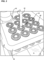
- FIG. 3 is a close-up view illustrating gromets 46 of the tool 10, shown with a golf club 12 inserted therein.
- FIG. 4 shows the golf club grip removal tool 10 in a dis-assembled configuration, illustrating the individual components of the tool 10.
- the tool 10 is generally comprised of an outer stand (i.e., base) 16 for providing stability to the tool 10.
- the stand 16 also provides portability aspects and allows the tool 10 to be transported to different environments or venues (e.g., retail stores, Pro-Shops, Tour vans, etc.) where club grips might be regularly replaced.
- the outer stand 16 defines a nest 18 for receiving a water container or tank 20.
- the outer stand 16 also defines a vertical support wall 22 for providing stability to the stand 16 when the water tank 20 has been placed therein.
- the vertical support wall 22 defines a handle 24 adjacent a top end 26 thereof for carrying the tool 10 for portability.
- the water tank 20 supports heated water 28 during use of the tool 10.
- the water tank 20 is removably placed on the stand 16, and a bottom/base 30 of the water tank 20 is supported by flanges 32 defined by the stand 16 when the water tank 20 is placed within the nest 18.
- the water tank 20 also defines handles 34 for placement and removal thereof during assembly and disassembly of the tool 10.
- the water tank 20 is provided with a removable tank lid 36.
- the tank lid 36 may be formed from a polymeric construction.
- the tank lid 36 defines flexible latches 37 on opposing sides thereof.
- the flexible latches 37 are configured to snap over lip portions 39 defined around the opening of the water tank 20 for removably latching the lid 36 to the water tank 20.
- the lid portion 36 even though not fully sealing the water tank 20, still limits evaporation of water from the water tank 20.
- the tank lid 36 is designed to form part of a two-piece club support structure 38.
- the club support 38 is formed by the lid 36 and a generally U-shaped lower support structure 41 (e.g., formed of metal construction according to one example) that is attached to the lid 36.
- the lower support structure 41 is designed to nest within the water tank 20 during the use of the tool 10.
- the lower support structure 41 can be removably attached to the lid 36 in a variety of ways.
- the lower support structure 41 can include features for snap-fitting to the lid 36.
- the lower support structure 41 can be attached to the lid 36 via fasteners such as bolts.
- the lid portion 36 of the club support 38 comprises a plurality of openings 40, each for receiving a worn grip 42 of a club shaft 44.
- Each of the openings 40 is provided with a shaft gromet 46 that supports and stabilizes the golf clubs 12 during the use of the tool 10.
- the gromets 46 each define a notch 48 for flexible snap-in placement thereof around apertures defined by the openings 40 of lid portion 36 of the club support 38. Please refer to FIGS. 5-7 for different views of one of the gromets 46.
- the lower support structure 41 also defines openings 56 that are spaced apart from and vertically aligned with corresponding openings 40 of the tank lid portion 36 for allowing the golf club shafts 44 to be inserted through and stabilized during the use of the tool 10.
- the openings 56 of the lower support structure 41 also receive grommets similar to the grommets 46 that are provided on the tank lid 36.
- the grommets 46 for the lower club support 41 similar to those for the lid 36, each define a notch 48 for flexible snap-in placement thereof around apertures defined by the openings 56 of the lower club support 41.
- the lower club support 41 defines twelve openings 56 that are aligned with twelve openings 40 provided on the tank lid 36 for supporting twelve clubs 12 at the same time.
- the tank lid 36 includes two additional larger/oversized openings 40 adjacent the back side of the lid 36. These oversized openings 40 may be used for accommodating clubs 12 with larger grips such as putters.
- the water tank 20 receives the club support 38, the lower portion 41 of which is submerged within the water 28 during the operation of the tool 10.
- a heat source 60 is used to heat the water 28 and also provide a generally constant water temperature within the tank 20.
- a heat source 60 in the form of a sous vide water heater/circulator can be used.
- a sous vide type heater 60 can provide modularity and portability to the golf club grip removal tool 10 and can facilitate transport.
- the lid portion 36 of the club support 38 defines a cutout 62 for accommodating the sous vide type heater 60 when the heater 60 is placed within the water tank 20.
- the two-piece club support 38 provides stability to and supports the heater 60, while the heater 60 is operating to heat the water 28 and circulate the water 28 to keep the temperature generally constant.
- the sous vide heater 60 is provided with an operation switch 64 and a handle 66 for handling.
- the heat source 60 is used to bring up and maintain the water temperature generally to around 170 degrees F, preferably by a thermostat.
- a heat source 60 such as a sous vide heater/circulator that is a thermometer probe type heater, the heated water 28 can be in constant circulation around the water tank 20, limiting any significant temperature gradients within the water tank 20 for consistent performance.
- the water temperature may be between 150 to 190 degrees F. In other embodiments, the water temperature may be between 160 to 180 degrees F.
- all of the golf club shafts 44 are placed through the gromets 46 of the spaced apart and aligned openings 40/56 provided by the tank lid 36 and the attached lower support structure 41.
- An operator can insert each individual club 12 through the associated pair of gromets 46 until a cap of the grip 42 hits the base 30 of the water tank 20, while the grip 42 is being supported by the club support 38.
- the grips 42 of the clubs 12 do not have to be fully submerged into the water tank 20 in order for the device 10 to properly function. As long as at least a majority of a grip 42 is submerged under water, the device 10 performs as intended. According to certain examples, if approximately the entire grip except the last inch is submerged, the device 10 can properly function.
- the above process can be repeated for all of the clubs 12 to be re-gripped.
- the operator can remove each club 12 and cut the grip 42 in a standard fashion, repeating the process until all of the grips 42 and tape have been removed.
- a minimum of 3 minutes has been specified for keeping the grips 42 submerged, in other embodiments, a period of at least 2 to 2.5 minutes may be sufficient depending upon the water temperature.
- Submerging the worn grips 42 within water 28 having a temperature of around 170 degrees F for around a minimum of 3 minutes has been found to significantly soften the grips 42 themselves and the tape/adhesive on the shafts 44, reducing the time and effort needed to remove the grips 42 and the tape. And, pre-processing all of the golf clubs 12 at the same time significantly reduces the resources needed as compared to re-gripping clubs 12 one at a time.
- the heat source 60 can be turned-off.
- the water 28 is normally removed from the tank 20.
- the sous vide type heater 60 can be placed within the water tank 20 and held in place by the club support 38 during transport. This aids in the safe transit of the tool 10 if used in mobile environments such as a tour van and the like.
Landscapes
- Health & Medical Sciences (AREA)
- General Health & Medical Sciences (AREA)
- Physical Education & Sports Medicine (AREA)
- Chemical & Material Sciences (AREA)
- Organic Chemistry (AREA)
- Golf Clubs (AREA)
Abstract
Description
- This application claims the benefit of
U.S. Provisional Application Serial No. 63/604,017, filed November 29, 2023 - In the sport of golf, maintaining a peak grip performance of the golf club is fundamental to maximizing a player's potential. The golf club grips require regular replacement for peak performance. Conventional grip installation methods currently pose a few challenges for the re-gripping process. Grip and tape removal is normally seen as a substantial barrier to an efficient re-gripping process. Golf grips are normally adhered to the club shafts via double-sided tape. Over time, the tape tends to dry out and becomes challenging to remove. The dry tape tends to tear and leave residue behind, taking up significant time and effort during the re-gripping process. Golf players tend to see the grip and tape removal step as being the biggest hinderance in deciding when to replace grips.
- Further improvements in club re-gripping processes are desired. Specifically, solutions aimed at significantly reducing the effort and time needed to prepare the golf club for a new grip, improving the overall re-gripping process, are desired.
- The inventive aspects of the present disclosure aim to significantly reduce the challenges of removing the worn grip and the existing double-sided tape from a club shaft for preparing the club for the re-gripping process. In certain aspects, the present inventive concepts can reduce the time to remove both the grip and the tape by at least 50% as compared to conventional methods. Furthermore, the inventive aspects described herein allow the processing of the clubs in batches rather than individually.
- According to certain inventive aspects, the worn grips of the golf clubs are submerged into a tank of preheated water. In certain preferred embodiments, the water is set to a temperature of about 170 degrees Fahrenheit (F). In certain instances, the worn grips are submerged for at least 3 minutes. The pre-submerging of the worn grips in the preheated water for a predetermined amount of time significantly facilitates the grip and tape removal from the club shaft.
- According to one example embodiment, the inventive aspects utilize a tool/device that can allow the simultaneous submerging of multiple club shafts. According to one example, the tool/device can allow the simultaneous submerging or pre-processing of all thirteen clubs and a putter. Compared to a conventional method that normally utilizes a heat gun to soften the tape adhesive on a single club at a time, the inventive solutions allow the pre-processing of multiple grips, significantly reducing the time for the re-gripping process (e.g., by over 50%).
- According to one aspect, the specification describes a golf club grip removal tool comprising a water container, a base for removably supporting the water container, a heat source for maintaining water within the water container at a generally constant temperature, and a golf club support structure defining an opening for receiving at least a portion of a shaft of the golf club, the golf club support structure configured to support the golf club shaft within the water container in a stable manner. According to certain examples, the water container may include a removable lid portion for limiting evaporation of water from the water container, the lid defining a part of the golf club support structure.
- According to another aspect, the disclosure is directed to a method for pre-processing a golf club grip for later removal, the method comprising submerging a golf club grip that is to be removed from a shaft of the golf club within a water container, wherein the water within the water container is generally around a temperature of about 150 to 190 degrees F, and leaving the shaft of the golf club with the grip within the water container for a minimum of about 3 minutes.
- The method may further comprise keeping the water within the water container at a generally constant temperature during the submergence of the golf club grip. The method may further comprisemaintaining the water temperature within the water container at a generally constant temperature via a heat source during the pre-processing of the golf club grip. The method may further compriseusing a removable heater within the water container as the heat source for keeping the water temperature generally constant. The removable heater may be a sous vide type heater. The method may further comprise submerging a plurality of golf club grips within the water container, leaving each golf club shaft within the water container for a minimum of about 3 minutes before removal. The water within the water container may be generally around a temperature of about 160 to 180 degrees F. The water within the water container may be generally around a temperature of about 170 degrees F.
- According to another aspect, the disclosure is directed to a method of removing a golf club grip from a shaft of a golf club, the method comprising pre-processing the golf club grip for removal by submerging the golf club grip within a water container, wherein the water within the water container is generally around a temperature of about 150 to 190 degrees F, leaving the shaft of the golf club with the grip within the water container for a minimum of about 3 minutes, and removing the golf club shaft from the water container and removing the grip from the shaft. The method may further comprise pre-processing a plurality of golf club grips at the same time by submerging the golf club grips within the water container and leaving the shaft of each golf club within the water container for a minimum of about 3 minutes before removing one of the golf club shafts from the water container and removing the grip from the shaft. The method may further comprise maintaining the water temperature within the water container at a generally constant temperature via a heat source during the pre-processing of the golf club grip. The method may further comprise using a removable heater within the water container as the heat source for keeping the water temperature generally constant. The removable heater may be a sous vide type heater. The water within the water container may be generally around a temperature of about 160 to 180 degrees F. The water within the water container may be generally around a temperature of about 170 degrees F.
- The accompanying drawings are included to provide a further understanding of the inventive aspects of the present disclosure and are incorporated in and constitute a part of this specification. The drawings illustrate exemplary embodiments of the present disclosure and together with the description serve to further explain the principles of the disclosure. Other aspects of the present disclosure and many of the advantages of the present disclosure will be readily appreciated as the present disclosure becomes better understood by reference to the following Detailed Description when considered in connection with the accompanying drawings.
-
FIG. 1A is a perspective view of a golf club grip removal tool/device having features that are examples of inventive aspects in accordance with the present disclosure. -
FIG. 1B is a side view of the golf club grip removal tool ofFIG. 1 . -
FIG. 2 is another perspective view of the golf club grip removal tool ofFIG. 1 , shown with a number of golf clubs placed therein for processing. -
FIG. 3 is a close-up view illustrating the gromets of the tool ofFIG. 2 , shown with a golf club inserted therein. -
FIG. 4 shows the golf club grip removal tool in a dis-assembled configuration, illustrating the individual components of the tool. -
FIG. 5 is a top perspective view of one of the gromets that are provided as part of the club support used for providing stability to the golf clubs during the use of the tool ofFIGS. 1-4 . -
FIG. 6 illustrates a bottom perspective view of the gromet ofFIG. 5 . -
FIG. 7 illustrates a side view of the gromet ofFIG. 5 . - The present disclosure is directed to embodiments of golf club grip removal tools and methods of use thereof.
- Generally, according to certain inventive aspects, the worn grips of the golf clubs are submerged into a tank of preheated water. In certain preferred embodiments, the water is set to a temperature of about 170 degrees F. The worn grips are submerged for at least 3 minutes in certain instances. The pre-submerging of the worn grips in the preheated water for a predetermined amount of time significantly facilitates the grip and tape removal from the club shaft.
- According to one example embodiment, the inventive aspects utilize a tool/device that can allow the simultaneous submerging of multiple club shafts. According to one example, the tool can allow the simultaneous submerging or pre-processing of all thirteen clubs and a putter. Compared to conventional methods that might normally utilize a heat gun to soften the tape adhesive one club at a time, the inventive solutions allow the pre-processing of multiple grips, significantly reducing the time for the re-gripping process (e.g., by over 50%).
- Referring now to
FIGS. 1-7 , one example of a golf clubgrip removal tool 10 is illustrated.FIGS. 1A and1B illustrate the golf clubgrip removal tool 10 in a fully assembled state.FIG. 2 is a perspective view of the golf clubgrip removal tool 10, shown with a number ofgolf clubs 12 placed therein for processing.FIG. 3 is a close-up view illustrating gromets 46 of thetool 10, shown with agolf club 12 inserted therein. And,FIG. 4 shows the golf clubgrip removal tool 10 in a dis-assembled configuration, illustrating the individual components of thetool 10. - As shown specifically in the disassembled view of
FIG. 4 , thetool 10 is generally comprised of an outer stand (i.e., base) 16 for providing stability to thetool 10. Thestand 16 also provides portability aspects and allows thetool 10 to be transported to different environments or venues (e.g., retail stores, Pro-Shops, Tour vans, etc.) where club grips might be regularly replaced. - The
outer stand 16 defines anest 18 for receiving a water container ortank 20. Theouter stand 16 also defines avertical support wall 22 for providing stability to thestand 16 when thewater tank 20 has been placed therein. Thevertical support wall 22 defines ahandle 24 adjacent atop end 26 thereof for carrying thetool 10 for portability. - The
water tank 20 supports heatedwater 28 during use of thetool 10. Thewater tank 20 is removably placed on thestand 16, and a bottom/base 30 of thewater tank 20 is supported byflanges 32 defined by thestand 16 when thewater tank 20 is placed within thenest 18. - The
water tank 20 also defineshandles 34 for placement and removal thereof during assembly and disassembly of thetool 10. - Still referring to
FIG. 4 , thewater tank 20 is provided with aremovable tank lid 36. Thetank lid 36 may be formed from a polymeric construction. Thetank lid 36 definesflexible latches 37 on opposing sides thereof. The flexible latches 37 are configured to snap overlip portions 39 defined around the opening of thewater tank 20 for removably latching thelid 36 to thewater tank 20. According to certain inventive aspects, thelid portion 36, even though not fully sealing thewater tank 20, still limits evaporation of water from thewater tank 20. - As shown in the figures, the
tank lid 36 is designed to form part of a two-piececlub support structure 38. In the depicted example, theclub support 38 is formed by thelid 36 and a generally U-shaped lower support structure 41 (e.g., formed of metal construction according to one example) that is attached to thelid 36. Thelower support structure 41 is designed to nest within thewater tank 20 during the use of thetool 10. Thelower support structure 41 can be removably attached to thelid 36 in a variety of ways. According to certain examples, thelower support structure 41 can include features for snap-fitting to thelid 36. And, according to certain other examples, thelower support structure 41 can be attached to thelid 36 via fasteners such as bolts. - As shown, the
lid portion 36 of theclub support 38 comprises a plurality ofopenings 40, each for receiving aworn grip 42 of aclub shaft 44. Each of theopenings 40 is provided with ashaft gromet 46 that supports and stabilizes thegolf clubs 12 during the use of thetool 10. Thegromets 46 each define anotch 48 for flexible snap-in placement thereof around apertures defined by theopenings 40 oflid portion 36 of theclub support 38. Please refer toFIGS. 5-7 for different views of one of thegromets 46. - Still referring to
FIG. 4 , as shown, thelower support structure 41 also definesopenings 56 that are spaced apart from and vertically aligned with correspondingopenings 40 of thetank lid portion 36 for allowing thegolf club shafts 44 to be inserted through and stabilized during the use of thetool 10. Theopenings 56 of thelower support structure 41 also receive grommets similar to thegrommets 46 that are provided on thetank lid 36. Thegrommets 46 for thelower club support 41, similar to those for thelid 36, each define anotch 48 for flexible snap-in placement thereof around apertures defined by theopenings 56 of thelower club support 41. - In the depicted example, the
lower club support 41 defines twelveopenings 56 that are aligned with twelveopenings 40 provided on thetank lid 36 for supporting twelveclubs 12 at the same time. As also shown, thetank lid 36 includes two additional larger/oversized openings 40 adjacent the back side of thelid 36. Theseoversized openings 40 may be used for accommodatingclubs 12 with larger grips such as putters. - The
water tank 20 receives theclub support 38, thelower portion 41 of which is submerged within thewater 28 during the operation of thetool 10. After thewater tank 20 has been filled withwater 28, according to the inventive aspects, aheat source 60 is used to heat thewater 28 and also provide a generally constant water temperature within thetank 20. - According to one example embodiment, a
heat source 60 in the form of a sous vide water heater/circulator can be used. A sous videtype heater 60 can provide modularity and portability to the golf clubgrip removal tool 10 and can facilitate transport. - As shown in
FIGS. 1-4 , thelid portion 36 of theclub support 38 defines acutout 62 for accommodating the sous videtype heater 60 when theheater 60 is placed within thewater tank 20. When the sous videheater 60 is placed inside thewater tank 20, the two-piece club support 38 provides stability to and supports theheater 60, while theheater 60 is operating to heat thewater 28 and circulate thewater 28 to keep the temperature generally constant. - As shown, the sous vide
heater 60 is provided with anoperation switch 64 and ahandle 66 for handling. - Still referring to
FIGS. 1-7 of the application, during use of thetool 10, once thetool 10 has been assembled and thewater tank 20 has been filled withwater 28, theheat source 60 is used to bring up and maintain the water temperature generally to around 170 degrees F, preferably by a thermostat. By using aheat source 60 such as a sous vide heater/circulator that is a thermometer probe type heater, theheated water 28 can be in constant circulation around thewater tank 20, limiting any significant temperature gradients within thewater tank 20 for consistent performance. - Although a temperature of 170 degrees F has been specified for the
inventive tool 10, in certain embodiments, the water temperature may be between 150 to 190 degrees F. In other embodiments, the water temperature may be between 160 to 180 degrees F. - Once the water temperature is at the desired level, all of the
golf club shafts 44 are placed through thegromets 46 of the spaced apart and alignedopenings 40/56 provided by thetank lid 36 and the attachedlower support structure 41. An operator can insert eachindividual club 12 through the associated pair ofgromets 46 until a cap of thegrip 42 hits thebase 30 of thewater tank 20, while thegrip 42 is being supported by theclub support 38. - It should be noted that the
grips 42 of theclubs 12 do not have to be fully submerged into thewater tank 20 in order for thedevice 10 to properly function. As long as at least a majority of agrip 42 is submerged under water, thedevice 10 performs as intended. According to certain examples, if approximately the entire grip except the last inch is submerged, thedevice 10 can properly function. - The above process can be repeated for all of the
clubs 12 to be re-gripped. Once theworn grips 42 have been submerged for a predetermined amount of time (preferably a minimum of 3 minutes), the operator can remove eachclub 12 and cut thegrip 42 in a standard fashion, repeating the process until all of thegrips 42 and tape have been removed. Although a minimum of 3 minutes has been specified for keeping thegrips 42 submerged, in other embodiments, a period of at least 2 to 2.5 minutes may be sufficient depending upon the water temperature. - Submerging the
worn grips 42 withinwater 28 having a temperature of around 170 degrees F for around a minimum of 3 minutes has been found to significantly soften thegrips 42 themselves and the tape/adhesive on theshafts 44, reducing the time and effort needed to remove thegrips 42 and the tape. And, pre-processing all of thegolf clubs 12 at the same time significantly reduces the resources needed as compared tore-gripping clubs 12 one at a time. - Once the tool/
device 10 has been used to pre-process thegolf shafts 44 for re-gripping, theheat source 60 can be turned-off. - For transportation of the
tool 10, thewater 28 is normally removed from thetank 20. The sous videtype heater 60 can be placed within thewater tank 20 and held in place by theclub support 38 during transport. This aids in the safe transit of thetool 10 if used in mobile environments such as a tour van and the like. - The above specification, examples provide a complete description of the manufacture and use of the disclosure. Since many embodiments of the disclosure can be made without departing from the spirit and scope of the inventive aspects, the inventive aspects reside in the claims hereinafter appended.
Claims (15)
- A golf club grip removal tool comprising:a water container;a base for removably supporting the water container;a heat source for maintaining water within the water container at a generally constant temperature; anda golf club support structure defining an opening for receiving at least a portion of a shaft of a golf club, the golf club support structure configured to support the golf club shaft within the water container in a stable manner.
- The golf club grip removal tool of claim 1, wherein the golf club support structure is configured to support a plurality of golf club shafts within the water container in a stable manner.
- The golf club grip removal tool of claim 1 or claim 2, wherein the golf club support structure defines a plurality of the openings, each for receiving a shaft of a separate golf club.
- The golf club grip removal tool of any preceding claim, wherein the opening for receiving the shaft of the golf club defines a flexible gromet that frictionally holds the shaft of the golf club in a stable manner.
- The golf club grip removal tool of any preceding claim, wherein the base defines a handle for transportation thereof.
- The golf club grip removal tool of any preceding claim, wherein the heat source is defined by a removable heater that can be removed from the water container.
- The golf club grip removal tool of claim 6, wherein the removable heater is defined by a thermometer probe type heater.
- The golf club grip removal tool of claim 7, wherein the probe type heater is defined by a sous vide type heater.
- The golf club grip removal tool of any preceding claim, wherein the golf club support structure is at least partially positioned within the water container.
- The golf club removal tool of any preceding claim, wherein the golf club support structure is at least partially constructed out of metal.
- The golf club grip removal tool of any preceding claim, wherein the water container defines a handle for transportation thereof.
- The golf club grip removal tool of any preceding claim, wherein the water container includes a removable lid portion for limiting evaporation of water from the water container.
- The golf club grip removal tool of claim 12, wherein the removable lid portion defines a part of the golf club support structure such that the lid portion defines the opening for receiving at least a portion of a shaft of a golf club.
- A method for pre-processing a golf club grip for later removal, the method comprising:- submerging a golf club grip that is to be removed from a shaft of a golf club within a water container, wherein water within the water container is generally around a temperature of about 150 to 190 degrees F; and- leaving the shaft of the golf club with the grip within the water container for a minimum of about 3 minutes.
- A method of removing a golf club grip from a shaft of a golf club, the method comprising:- pre-processing the golf club grip for removal as recited in claim 14; and- removing the golf club shaft from the water container and removing the grip from the shaft.
Applications Claiming Priority (1)
| Application Number | Priority Date | Filing Date | Title |
|---|---|---|---|
| US202363604017P | 2023-11-29 | 2023-11-29 |
Publications (3)
| Publication Number | Publication Date |
|---|---|
| EP4563203A2 true EP4563203A2 (en) | 2025-06-04 |
| EP4563203A3 EP4563203A3 (en) | 2025-07-30 |
| EP4563203B1 EP4563203B1 (en) | 2026-05-20 |
Family
ID=93741634
Family Applications (1)
| Application Number | Title | Priority Date | Filing Date |
|---|---|---|---|
| EP24216101.6A Active EP4563203B1 (en) | 2023-11-29 | 2024-11-28 | TOOL FOR REMOVING THE GOLF CLUB GRIP |
Country Status (4)
| Country | Link |
|---|---|
| US (1) | US20250170466A1 (en) |
| EP (1) | EP4563203B1 (en) |
| JP (1) | JP2025097926A (en) |
| KR (1) | KR20250081810A (en) |
Family Cites Families (6)
| Publication number | Priority date | Publication date | Assignee | Title |
|---|---|---|---|---|
| US5094557A (en) * | 1989-12-08 | 1992-03-10 | Nelson Peter K | Golf club renovating device |
| US6041795A (en) * | 1998-04-15 | 2000-03-28 | Steiner; Sidney B. | Computer controlled, multi-bay ultrasonic golf club cleaning machine |
| KR20010063871A (en) * | 1999-12-24 | 2001-07-09 | 정봉필 | Golf club cleaner |
| GB2394406A (en) * | 2002-10-24 | 2004-04-28 | Proclean Uk Ltd | Ultrasonic cleaning apparatus for golf clubs |
| GB2410889A (en) * | 2004-02-12 | 2005-08-17 | Proclean Uk Ltd | Ultrasonic golf club cleaning apparatus |
| CN208694196U (en) * | 2018-07-17 | 2019-04-05 | 隆回县三百运动用品有限公司 | A kind of Special Automatic cleaning machine of golf club |
-
2024
- 2024-11-26 US US18/959,865 patent/US20250170466A1/en active Pending
- 2024-11-28 EP EP24216101.6A patent/EP4563203B1/en active Active
- 2024-11-28 KR KR1020240174117A patent/KR20250081810A/en active Pending
- 2024-11-29 JP JP2024208633A patent/JP2025097926A/en active Pending
Also Published As
| Publication number | Publication date |
|---|---|
| US20250170466A1 (en) | 2025-05-29 |
| JP2025097926A (en) | 2025-07-01 |
| KR20250081810A (en) | 2025-06-05 |
| EP4563203A3 (en) | 2025-07-30 |
| EP4563203B1 (en) | 2026-05-20 |
Similar Documents
| Publication | Publication Date | Title |
|---|---|---|
| US4982966A (en) | Ring toss game apparatus | |
| US7805959B2 (en) | Cup holder for drinking game | |
| US6254100B1 (en) | Archery target with replaceable target section | |
| US7963406B2 (en) | Long gun storage method | |
| US10077931B2 (en) | Cooler or cooler insert and methods of fabrication thereof | |
| US20250170466A1 (en) | Golf club grip removal tool | |
| US9233285B2 (en) | Golf club holder | |
| US20030178383A1 (en) | Sports equipment storage rack | |
| US20140331543A1 (en) | Ice Fishing Tip-Up and Gadget Holder System, Kit and Method | |
| US6471103B1 (en) | Carrying and/or storing device | |
| US4232596A (en) | Low heat capacity fry basket assembly | |
| WO2014127248A1 (en) | Storage system | |
| CA2282464A1 (en) | A golf bag | |
| EP3066954A1 (en) | Magnetic silicone brush holders | |
| US20140097101A1 (en) | Arrow retainer | |
| US5385160A (en) | Golf club cleaner | |
| US20180028884A1 (en) | Golf Club Organizer Apparatus | |
| US11019812B1 (en) | Tackle container and kit | |
| US5858263A (en) | Ice puck mold and storage system | |
| US5058396A (en) | Rapid chilling system | |
| US7070524B1 (en) | Weighted hockey stick | |
| US20030051607A1 (en) | Shish Kabob apparatus | |
| WO1996041660A1 (en) | Beverage storage apparatus for use with a golf bag | |
| US20170172339A1 (en) | Tea infuser | |
| US20070017836A1 (en) | Roller rest enclosure |
Legal Events
| Date | Code | Title | Description |
|---|---|---|---|
| PUAI | Public reference made under article 153(3) epc to a published international application that has entered the european phase |
Free format text: ORIGINAL CODE: 0009012 |
|
| STAA | Information on the status of an ep patent application or granted ep patent |
Free format text: STATUS: THE APPLICATION HAS BEEN PUBLISHED |
|
| AK | Designated contracting states |
Kind code of ref document: A2 Designated state(s): AL AT BE BG CH CY CZ DE DK EE ES FI FR GB GR HR HU IE IS IT LI LT LU LV MC ME MK MT NL NO PL PT RO RS SE SI SK SM TR |
|
| PUAL | Search report despatched |
Free format text: ORIGINAL CODE: 0009013 |
|
| AK | Designated contracting states |
Kind code of ref document: A3 Designated state(s): AL AT BE BG CH CY CZ DE DK EE ES FI FR GB GR HR HU IE IS IT LI LT LU LV MC ME MK MT NL NO PL PT RO RS SE SI SK SM TR |
|
| RIC1 | Information provided on ipc code assigned before grant |
Ipc: A63B 60/36 20150101AFI20250625BHEP Ipc: A63B 53/14 20150101ALN20250625BHEP Ipc: A63B 60/14 20150101ALN20250625BHEP Ipc: A63B 60/62 20150101ALN20250625BHEP Ipc: A63B 57/60 20150101ALN20250625BHEP Ipc: A63B 102/32 20150101ALN20250625BHEP |
|
| STAA | Information on the status of an ep patent application or granted ep patent |
Free format text: STATUS: REQUEST FOR EXAMINATION WAS MADE |
|
| GRAP | Despatch of communication of intention to grant a patent |
Free format text: ORIGINAL CODE: EPIDOSNIGR1 |
|
| STAA | Information on the status of an ep patent application or granted ep patent |
Free format text: STATUS: GRANT OF PATENT IS INTENDED |
|
| 17P | Request for examination filed |
Effective date: 20260128 |
|
| RIC1 | Information provided on ipc code assigned before grant |
Ipc: A63B 60/36 20150101AFI20260204BHEP Ipc: A63B 53/14 20150101ALN20260204BHEP Ipc: A63B 60/14 20150101ALN20260204BHEP Ipc: A63B 60/62 20150101ALN20260204BHEP Ipc: A63B 57/60 20150101ALN20260204BHEP Ipc: A63B 102/32 20150101ALN20260204BHEP |
|
| INTG | Intention to grant announced |
Effective date: 20260223 |
|
| GRAS | Grant fee paid |
Free format text: ORIGINAL CODE: EPIDOSNIGR3 |
|
| GRAA | (expected) grant |
Free format text: ORIGINAL CODE: 0009210 |
|
| STAA | Information on the status of an ep patent application or granted ep patent |
Free format text: STATUS: THE PATENT HAS BEEN GRANTED |