EP4563124A1 - Expandable spinal implant - Google Patents
Expandable spinal implant Download PDFInfo
- Publication number
- EP4563124A1 EP4563124A1 EP23220316.6A EP23220316A EP4563124A1 EP 4563124 A1 EP4563124 A1 EP 4563124A1 EP 23220316 A EP23220316 A EP 23220316A EP 4563124 A1 EP4563124 A1 EP 4563124A1
- Authority
- EP
- European Patent Office
- Prior art keywords
- spinal implant
- expandable spinal
- expander component
- base portion
- flexible arms
- Prior art date
- Legal status (The legal status is an assumption and is not a legal conclusion. Google has not performed a legal analysis and makes no representation as to the accuracy of the status listed.)
- Granted
Links
Images




Classifications
-
- A—HUMAN NECESSITIES
- A61—MEDICAL OR VETERINARY SCIENCE; HYGIENE
- A61F—FILTERS IMPLANTABLE INTO BLOOD VESSELS; PROSTHESES; DEVICES PROVIDING PATENCY TO, OR PREVENTING COLLAPSING OF, TUBULAR STRUCTURES OF THE BODY, e.g. STENTS; ORTHOPAEDIC, NURSING OR CONTRACEPTIVE DEVICES; FOMENTATION; TREATMENT OR PROTECTION OF EYES OR EARS; BANDAGES, DRESSINGS OR ABSORBENT PADS; FIRST-AID KITS
- A61F2/00—Filters implantable into blood vessels; Prostheses, i.e. artificial substitutes or replacements for parts of the body; Appliances for connecting them with the body; Devices providing patency to, or preventing collapsing of, tubular structures of the body, e.g. stents
- A61F2/02—Prostheses implantable into the body
- A61F2/30—Joints
- A61F2/44—Joints for the spine, e.g. vertebrae, spinal discs
- A61F2/442—Intervertebral or spinal discs, e.g. resilient
- A61F2/4425—Intervertebral or spinal discs, e.g. resilient made of articulated components
-
- A—HUMAN NECESSITIES
- A61—MEDICAL OR VETERINARY SCIENCE; HYGIENE
- A61F—FILTERS IMPLANTABLE INTO BLOOD VESSELS; PROSTHESES; DEVICES PROVIDING PATENCY TO, OR PREVENTING COLLAPSING OF, TUBULAR STRUCTURES OF THE BODY, e.g. STENTS; ORTHOPAEDIC, NURSING OR CONTRACEPTIVE DEVICES; FOMENTATION; TREATMENT OR PROTECTION OF EYES OR EARS; BANDAGES, DRESSINGS OR ABSORBENT PADS; FIRST-AID KITS
- A61F2/00—Filters implantable into blood vessels; Prostheses, i.e. artificial substitutes or replacements for parts of the body; Appliances for connecting them with the body; Devices providing patency to, or preventing collapsing of, tubular structures of the body, e.g. stents
- A61F2/02—Prostheses implantable into the body
- A61F2/30—Joints
- A61F2/44—Joints for the spine, e.g. vertebrae, spinal discs
- A61F2/4455—Joints for the spine, e.g. vertebrae, spinal discs for the fusion of spinal bodies, e.g. intervertebral fusion of adjacent spinal bodies, e.g. fusion cages
-
- A—HUMAN NECESSITIES
- A61—MEDICAL OR VETERINARY SCIENCE; HYGIENE
- A61F—FILTERS IMPLANTABLE INTO BLOOD VESSELS; PROSTHESES; DEVICES PROVIDING PATENCY TO, OR PREVENTING COLLAPSING OF, TUBULAR STRUCTURES OF THE BODY, e.g. STENTS; ORTHOPAEDIC, NURSING OR CONTRACEPTIVE DEVICES; FOMENTATION; TREATMENT OR PROTECTION OF EYES OR EARS; BANDAGES, DRESSINGS OR ABSORBENT PADS; FIRST-AID KITS
- A61F2/00—Filters implantable into blood vessels; Prostheses, i.e. artificial substitutes or replacements for parts of the body; Appliances for connecting them with the body; Devices providing patency to, or preventing collapsing of, tubular structures of the body, e.g. stents
- A61F2/02—Prostheses implantable into the body
- A61F2/30—Joints
- A61F2/44—Joints for the spine, e.g. vertebrae, spinal discs
- A61F2/4455—Joints for the spine, e.g. vertebrae, spinal discs for the fusion of spinal bodies, e.g. intervertebral fusion of adjacent spinal bodies, e.g. fusion cages
- A61F2/447—Joints for the spine, e.g. vertebrae, spinal discs for the fusion of spinal bodies, e.g. intervertebral fusion of adjacent spinal bodies, e.g. fusion cages substantially parallelepipedal, e.g. having a rectangular or trapezoidal cross-section
-
- A—HUMAN NECESSITIES
- A61—MEDICAL OR VETERINARY SCIENCE; HYGIENE
- A61F—FILTERS IMPLANTABLE INTO BLOOD VESSELS; PROSTHESES; DEVICES PROVIDING PATENCY TO, OR PREVENTING COLLAPSING OF, TUBULAR STRUCTURES OF THE BODY, e.g. STENTS; ORTHOPAEDIC, NURSING OR CONTRACEPTIVE DEVICES; FOMENTATION; TREATMENT OR PROTECTION OF EYES OR EARS; BANDAGES, DRESSINGS OR ABSORBENT PADS; FIRST-AID KITS
- A61F2/00—Filters implantable into blood vessels; Prostheses, i.e. artificial substitutes or replacements for parts of the body; Appliances for connecting them with the body; Devices providing patency to, or preventing collapsing of, tubular structures of the body, e.g. stents
- A61F2/02—Prostheses implantable into the body
- A61F2/30—Joints
- A61F2/46—Special tools for implanting artificial joints
- A61F2/4637—Special tools for implanting artificial joints for connecting or disconnecting two parts of a prosthesis
-
- A—HUMAN NECESSITIES
- A61—MEDICAL OR VETERINARY SCIENCE; HYGIENE
- A61F—FILTERS IMPLANTABLE INTO BLOOD VESSELS; PROSTHESES; DEVICES PROVIDING PATENCY TO, OR PREVENTING COLLAPSING OF, TUBULAR STRUCTURES OF THE BODY, e.g. STENTS; ORTHOPAEDIC, NURSING OR CONTRACEPTIVE DEVICES; FOMENTATION; TREATMENT OR PROTECTION OF EYES OR EARS; BANDAGES, DRESSINGS OR ABSORBENT PADS; FIRST-AID KITS
- A61F2/00—Filters implantable into blood vessels; Prostheses, i.e. artificial substitutes or replacements for parts of the body; Appliances for connecting them with the body; Devices providing patency to, or preventing collapsing of, tubular structures of the body, e.g. stents
- A61F2/02—Prostheses implantable into the body
- A61F2/30—Joints
- A61F2/44—Joints for the spine, e.g. vertebrae, spinal discs
- A61F2/4455—Joints for the spine, e.g. vertebrae, spinal discs for the fusion of spinal bodies, e.g. intervertebral fusion of adjacent spinal bodies, e.g. fusion cages
- A61F2/4465—Joints for the spine, e.g. vertebrae, spinal discs for the fusion of spinal bodies, e.g. intervertebral fusion of adjacent spinal bodies, e.g. fusion cages having a circular or kidney shaped cross-section substantially perpendicular to the axis of the spine
-
- A—HUMAN NECESSITIES
- A61—MEDICAL OR VETERINARY SCIENCE; HYGIENE
- A61F—FILTERS IMPLANTABLE INTO BLOOD VESSELS; PROSTHESES; DEVICES PROVIDING PATENCY TO, OR PREVENTING COLLAPSING OF, TUBULAR STRUCTURES OF THE BODY, e.g. STENTS; ORTHOPAEDIC, NURSING OR CONTRACEPTIVE DEVICES; FOMENTATION; TREATMENT OR PROTECTION OF EYES OR EARS; BANDAGES, DRESSINGS OR ABSORBENT PADS; FIRST-AID KITS
- A61F2/00—Filters implantable into blood vessels; Prostheses, i.e. artificial substitutes or replacements for parts of the body; Appliances for connecting them with the body; Devices providing patency to, or preventing collapsing of, tubular structures of the body, e.g. stents
- A61F2/02—Prostheses implantable into the body
- A61F2/30—Joints
- A61F2002/30001—Additional features of subject-matter classified in A61F2/28, A61F2/30 and subgroups thereof
- A61F2002/30316—The prosthesis having different structural features at different locations within the same prosthesis; Connections between prosthetic parts; Special structural features of bone or joint prostheses not otherwise provided for
- A61F2002/30317—The prosthesis having different structural features at different locations within the same prosthesis
- A61F2002/30322—The prosthesis having different structural features at different locations within the same prosthesis differing in surface structures
-
- A—HUMAN NECESSITIES
- A61—MEDICAL OR VETERINARY SCIENCE; HYGIENE
- A61F—FILTERS IMPLANTABLE INTO BLOOD VESSELS; PROSTHESES; DEVICES PROVIDING PATENCY TO, OR PREVENTING COLLAPSING OF, TUBULAR STRUCTURES OF THE BODY, e.g. STENTS; ORTHOPAEDIC, NURSING OR CONTRACEPTIVE DEVICES; FOMENTATION; TREATMENT OR PROTECTION OF EYES OR EARS; BANDAGES, DRESSINGS OR ABSORBENT PADS; FIRST-AID KITS
- A61F2/00—Filters implantable into blood vessels; Prostheses, i.e. artificial substitutes or replacements for parts of the body; Appliances for connecting them with the body; Devices providing patency to, or preventing collapsing of, tubular structures of the body, e.g. stents
- A61F2/02—Prostheses implantable into the body
- A61F2/30—Joints
- A61F2002/30001—Additional features of subject-matter classified in A61F2/28, A61F2/30 and subgroups thereof
- A61F2002/30316—The prosthesis having different structural features at different locations within the same prosthesis; Connections between prosthetic parts; Special structural features of bone or joint prostheses not otherwise provided for
- A61F2002/30317—The prosthesis having different structural features at different locations within the same prosthesis
- A61F2002/30327—The prosthesis having different structural features at different locations within the same prosthesis differing in diameter
-
- A—HUMAN NECESSITIES
- A61—MEDICAL OR VETERINARY SCIENCE; HYGIENE
- A61F—FILTERS IMPLANTABLE INTO BLOOD VESSELS; PROSTHESES; DEVICES PROVIDING PATENCY TO, OR PREVENTING COLLAPSING OF, TUBULAR STRUCTURES OF THE BODY, e.g. STENTS; ORTHOPAEDIC, NURSING OR CONTRACEPTIVE DEVICES; FOMENTATION; TREATMENT OR PROTECTION OF EYES OR EARS; BANDAGES, DRESSINGS OR ABSORBENT PADS; FIRST-AID KITS
- A61F2/00—Filters implantable into blood vessels; Prostheses, i.e. artificial substitutes or replacements for parts of the body; Appliances for connecting them with the body; Devices providing patency to, or preventing collapsing of, tubular structures of the body, e.g. stents
- A61F2/02—Prostheses implantable into the body
- A61F2/30—Joints
- A61F2002/30001—Additional features of subject-matter classified in A61F2/28, A61F2/30 and subgroups thereof
- A61F2002/30316—The prosthesis having different structural features at different locations within the same prosthesis; Connections between prosthetic parts; Special structural features of bone or joint prostheses not otherwise provided for
- A61F2002/30329—Connections or couplings between prosthetic parts, e.g. between modular parts; Connecting elements
- A61F2002/30331—Connections or couplings between prosthetic parts, e.g. between modular parts; Connecting elements made by longitudinally pushing a protrusion into a complementarily-shaped recess, e.g. held by friction fit
-
- A—HUMAN NECESSITIES
- A61—MEDICAL OR VETERINARY SCIENCE; HYGIENE
- A61F—FILTERS IMPLANTABLE INTO BLOOD VESSELS; PROSTHESES; DEVICES PROVIDING PATENCY TO, OR PREVENTING COLLAPSING OF, TUBULAR STRUCTURES OF THE BODY, e.g. STENTS; ORTHOPAEDIC, NURSING OR CONTRACEPTIVE DEVICES; FOMENTATION; TREATMENT OR PROTECTION OF EYES OR EARS; BANDAGES, DRESSINGS OR ABSORBENT PADS; FIRST-AID KITS
- A61F2/00—Filters implantable into blood vessels; Prostheses, i.e. artificial substitutes or replacements for parts of the body; Appliances for connecting them with the body; Devices providing patency to, or preventing collapsing of, tubular structures of the body, e.g. stents
- A61F2/02—Prostheses implantable into the body
- A61F2/30—Joints
- A61F2002/30001—Additional features of subject-matter classified in A61F2/28, A61F2/30 and subgroups thereof
- A61F2002/30316—The prosthesis having different structural features at different locations within the same prosthesis; Connections between prosthetic parts; Special structural features of bone or joint prostheses not otherwise provided for
- A61F2002/30329—Connections or couplings between prosthetic parts, e.g. between modular parts; Connecting elements
- A61F2002/30383—Connections or couplings between prosthetic parts, e.g. between modular parts; Connecting elements made by laterally inserting a protrusion, e.g. a rib into a complementarily-shaped groove
- A61F2002/3039—Connections or couplings between prosthetic parts, e.g. between modular parts; Connecting elements made by laterally inserting a protrusion, e.g. a rib into a complementarily-shaped groove with possibility of relative movement of the rib within the groove
- A61F2002/30398—Sliding
-
- A—HUMAN NECESSITIES
- A61—MEDICAL OR VETERINARY SCIENCE; HYGIENE
- A61F—FILTERS IMPLANTABLE INTO BLOOD VESSELS; PROSTHESES; DEVICES PROVIDING PATENCY TO, OR PREVENTING COLLAPSING OF, TUBULAR STRUCTURES OF THE BODY, e.g. STENTS; ORTHOPAEDIC, NURSING OR CONTRACEPTIVE DEVICES; FOMENTATION; TREATMENT OR PROTECTION OF EYES OR EARS; BANDAGES, DRESSINGS OR ABSORBENT PADS; FIRST-AID KITS
- A61F2/00—Filters implantable into blood vessels; Prostheses, i.e. artificial substitutes or replacements for parts of the body; Appliances for connecting them with the body; Devices providing patency to, or preventing collapsing of, tubular structures of the body, e.g. stents
- A61F2/02—Prostheses implantable into the body
- A61F2/30—Joints
- A61F2002/30001—Additional features of subject-matter classified in A61F2/28, A61F2/30 and subgroups thereof
- A61F2002/30316—The prosthesis having different structural features at different locations within the same prosthesis; Connections between prosthetic parts; Special structural features of bone or joint prostheses not otherwise provided for
- A61F2002/30329—Connections or couplings between prosthetic parts, e.g. between modular parts; Connecting elements
- A61F2002/30405—Connections or couplings between prosthetic parts, e.g. between modular parts; Connecting elements made by screwing complementary threads machined on the parts themselves
-
- A—HUMAN NECESSITIES
- A61—MEDICAL OR VETERINARY SCIENCE; HYGIENE
- A61F—FILTERS IMPLANTABLE INTO BLOOD VESSELS; PROSTHESES; DEVICES PROVIDING PATENCY TO, OR PREVENTING COLLAPSING OF, TUBULAR STRUCTURES OF THE BODY, e.g. STENTS; ORTHOPAEDIC, NURSING OR CONTRACEPTIVE DEVICES; FOMENTATION; TREATMENT OR PROTECTION OF EYES OR EARS; BANDAGES, DRESSINGS OR ABSORBENT PADS; FIRST-AID KITS
- A61F2/00—Filters implantable into blood vessels; Prostheses, i.e. artificial substitutes or replacements for parts of the body; Appliances for connecting them with the body; Devices providing patency to, or preventing collapsing of, tubular structures of the body, e.g. stents
- A61F2/02—Prostheses implantable into the body
- A61F2/30—Joints
- A61F2002/30001—Additional features of subject-matter classified in A61F2/28, A61F2/30 and subgroups thereof
- A61F2002/30316—The prosthesis having different structural features at different locations within the same prosthesis; Connections between prosthetic parts; Special structural features of bone or joint prostheses not otherwise provided for
- A61F2002/30329—Connections or couplings between prosthetic parts, e.g. between modular parts; Connecting elements
- A61F2002/30471—Connections or couplings between prosthetic parts, e.g. between modular parts; Connecting elements connected by a hinged linkage mechanism, e.g. of the single-bar or multi-bar linkage type
-
- A—HUMAN NECESSITIES
- A61—MEDICAL OR VETERINARY SCIENCE; HYGIENE
- A61F—FILTERS IMPLANTABLE INTO BLOOD VESSELS; PROSTHESES; DEVICES PROVIDING PATENCY TO, OR PREVENTING COLLAPSING OF, TUBULAR STRUCTURES OF THE BODY, e.g. STENTS; ORTHOPAEDIC, NURSING OR CONTRACEPTIVE DEVICES; FOMENTATION; TREATMENT OR PROTECTION OF EYES OR EARS; BANDAGES, DRESSINGS OR ABSORBENT PADS; FIRST-AID KITS
- A61F2/00—Filters implantable into blood vessels; Prostheses, i.e. artificial substitutes or replacements for parts of the body; Appliances for connecting them with the body; Devices providing patency to, or preventing collapsing of, tubular structures of the body, e.g. stents
- A61F2/02—Prostheses implantable into the body
- A61F2/30—Joints
- A61F2002/30001—Additional features of subject-matter classified in A61F2/28, A61F2/30 and subgroups thereof
- A61F2002/30316—The prosthesis having different structural features at different locations within the same prosthesis; Connections between prosthetic parts; Special structural features of bone or joint prostheses not otherwise provided for
- A61F2002/30329—Connections or couplings between prosthetic parts, e.g. between modular parts; Connecting elements
- A61F2002/30474—Connections or couplings between prosthetic parts, e.g. between modular parts; Connecting elements using an intermediate sleeve interposed between both prosthetic parts to be coupled
-
- A—HUMAN NECESSITIES
- A61—MEDICAL OR VETERINARY SCIENCE; HYGIENE
- A61F—FILTERS IMPLANTABLE INTO BLOOD VESSELS; PROSTHESES; DEVICES PROVIDING PATENCY TO, OR PREVENTING COLLAPSING OF, TUBULAR STRUCTURES OF THE BODY, e.g. STENTS; ORTHOPAEDIC, NURSING OR CONTRACEPTIVE DEVICES; FOMENTATION; TREATMENT OR PROTECTION OF EYES OR EARS; BANDAGES, DRESSINGS OR ABSORBENT PADS; FIRST-AID KITS
- A61F2/00—Filters implantable into blood vessels; Prostheses, i.e. artificial substitutes or replacements for parts of the body; Appliances for connecting them with the body; Devices providing patency to, or preventing collapsing of, tubular structures of the body, e.g. stents
- A61F2/02—Prostheses implantable into the body
- A61F2/30—Joints
- A61F2002/30001—Additional features of subject-matter classified in A61F2/28, A61F2/30 and subgroups thereof
- A61F2002/30316—The prosthesis having different structural features at different locations within the same prosthesis; Connections between prosthetic parts; Special structural features of bone or joint prostheses not otherwise provided for
- A61F2002/30329—Connections or couplings between prosthetic parts, e.g. between modular parts; Connecting elements
- A61F2002/30476—Connections or couplings between prosthetic parts, e.g. between modular parts; Connecting elements locked by an additional locking mechanism
-
- A—HUMAN NECESSITIES
- A61—MEDICAL OR VETERINARY SCIENCE; HYGIENE
- A61F—FILTERS IMPLANTABLE INTO BLOOD VESSELS; PROSTHESES; DEVICES PROVIDING PATENCY TO, OR PREVENTING COLLAPSING OF, TUBULAR STRUCTURES OF THE BODY, e.g. STENTS; ORTHOPAEDIC, NURSING OR CONTRACEPTIVE DEVICES; FOMENTATION; TREATMENT OR PROTECTION OF EYES OR EARS; BANDAGES, DRESSINGS OR ABSORBENT PADS; FIRST-AID KITS
- A61F2/00—Filters implantable into blood vessels; Prostheses, i.e. artificial substitutes or replacements for parts of the body; Appliances for connecting them with the body; Devices providing patency to, or preventing collapsing of, tubular structures of the body, e.g. stents
- A61F2/02—Prostheses implantable into the body
- A61F2/30—Joints
- A61F2002/30001—Additional features of subject-matter classified in A61F2/28, A61F2/30 and subgroups thereof
- A61F2002/30316—The prosthesis having different structural features at different locations within the same prosthesis; Connections between prosthetic parts; Special structural features of bone or joint prostheses not otherwise provided for
- A61F2002/30329—Connections or couplings between prosthetic parts, e.g. between modular parts; Connecting elements
- A61F2002/30476—Connections or couplings between prosthetic parts, e.g. between modular parts; Connecting elements locked by an additional locking mechanism
- A61F2002/30514—Connections or couplings between prosthetic parts, e.g. between modular parts; Connecting elements locked by an additional locking mechanism using a locking washer
-
- A—HUMAN NECESSITIES
- A61—MEDICAL OR VETERINARY SCIENCE; HYGIENE
- A61F—FILTERS IMPLANTABLE INTO BLOOD VESSELS; PROSTHESES; DEVICES PROVIDING PATENCY TO, OR PREVENTING COLLAPSING OF, TUBULAR STRUCTURES OF THE BODY, e.g. STENTS; ORTHOPAEDIC, NURSING OR CONTRACEPTIVE DEVICES; FOMENTATION; TREATMENT OR PROTECTION OF EYES OR EARS; BANDAGES, DRESSINGS OR ABSORBENT PADS; FIRST-AID KITS
- A61F2/00—Filters implantable into blood vessels; Prostheses, i.e. artificial substitutes or replacements for parts of the body; Appliances for connecting them with the body; Devices providing patency to, or preventing collapsing of, tubular structures of the body, e.g. stents
- A61F2/02—Prostheses implantable into the body
- A61F2/30—Joints
- A61F2002/30001—Additional features of subject-matter classified in A61F2/28, A61F2/30 and subgroups thereof
- A61F2002/30316—The prosthesis having different structural features at different locations within the same prosthesis; Connections between prosthetic parts; Special structural features of bone or joint prostheses not otherwise provided for
- A61F2002/30329—Connections or couplings between prosthetic parts, e.g. between modular parts; Connecting elements
- A61F2002/30476—Connections or couplings between prosthetic parts, e.g. between modular parts; Connecting elements locked by an additional locking mechanism
- A61F2002/30515—Connections or couplings between prosthetic parts, e.g. between modular parts; Connecting elements locked by an additional locking mechanism using a locking wedge or block
-
- A—HUMAN NECESSITIES
- A61—MEDICAL OR VETERINARY SCIENCE; HYGIENE
- A61F—FILTERS IMPLANTABLE INTO BLOOD VESSELS; PROSTHESES; DEVICES PROVIDING PATENCY TO, OR PREVENTING COLLAPSING OF, TUBULAR STRUCTURES OF THE BODY, e.g. STENTS; ORTHOPAEDIC, NURSING OR CONTRACEPTIVE DEVICES; FOMENTATION; TREATMENT OR PROTECTION OF EYES OR EARS; BANDAGES, DRESSINGS OR ABSORBENT PADS; FIRST-AID KITS
- A61F2/00—Filters implantable into blood vessels; Prostheses, i.e. artificial substitutes or replacements for parts of the body; Appliances for connecting them with the body; Devices providing patency to, or preventing collapsing of, tubular structures of the body, e.g. stents
- A61F2/02—Prostheses implantable into the body
- A61F2/30—Joints
- A61F2002/30001—Additional features of subject-matter classified in A61F2/28, A61F2/30 and subgroups thereof
- A61F2002/30316—The prosthesis having different structural features at different locations within the same prosthesis; Connections between prosthetic parts; Special structural features of bone or joint prostheses not otherwise provided for
- A61F2002/30329—Connections or couplings between prosthetic parts, e.g. between modular parts; Connecting elements
- A61F2002/30518—Connections or couplings between prosthetic parts, e.g. between modular parts; Connecting elements with possibility of relative movement between the prosthetic parts
- A61F2002/30528—Means for limiting said movement
-
- A—HUMAN NECESSITIES
- A61—MEDICAL OR VETERINARY SCIENCE; HYGIENE
- A61F—FILTERS IMPLANTABLE INTO BLOOD VESSELS; PROSTHESES; DEVICES PROVIDING PATENCY TO, OR PREVENTING COLLAPSING OF, TUBULAR STRUCTURES OF THE BODY, e.g. STENTS; ORTHOPAEDIC, NURSING OR CONTRACEPTIVE DEVICES; FOMENTATION; TREATMENT OR PROTECTION OF EYES OR EARS; BANDAGES, DRESSINGS OR ABSORBENT PADS; FIRST-AID KITS
- A61F2/00—Filters implantable into blood vessels; Prostheses, i.e. artificial substitutes or replacements for parts of the body; Appliances for connecting them with the body; Devices providing patency to, or preventing collapsing of, tubular structures of the body, e.g. stents
- A61F2/02—Prostheses implantable into the body
- A61F2/30—Joints
- A61F2002/30001—Additional features of subject-matter classified in A61F2/28, A61F2/30 and subgroups thereof
- A61F2002/30316—The prosthesis having different structural features at different locations within the same prosthesis; Connections between prosthetic parts; Special structural features of bone or joint prostheses not otherwise provided for
- A61F2002/30535—Special structural features of bone or joint prostheses not otherwise provided for
- A61F2002/30537—Special structural features of bone or joint prostheses not otherwise provided for adjustable
-
- A—HUMAN NECESSITIES
- A61—MEDICAL OR VETERINARY SCIENCE; HYGIENE
- A61F—FILTERS IMPLANTABLE INTO BLOOD VESSELS; PROSTHESES; DEVICES PROVIDING PATENCY TO, OR PREVENTING COLLAPSING OF, TUBULAR STRUCTURES OF THE BODY, e.g. STENTS; ORTHOPAEDIC, NURSING OR CONTRACEPTIVE DEVICES; FOMENTATION; TREATMENT OR PROTECTION OF EYES OR EARS; BANDAGES, DRESSINGS OR ABSORBENT PADS; FIRST-AID KITS
- A61F2/00—Filters implantable into blood vessels; Prostheses, i.e. artificial substitutes or replacements for parts of the body; Appliances for connecting them with the body; Devices providing patency to, or preventing collapsing of, tubular structures of the body, e.g. stents
- A61F2/02—Prostheses implantable into the body
- A61F2/30—Joints
- A61F2002/30001—Additional features of subject-matter classified in A61F2/28, A61F2/30 and subgroups thereof
- A61F2002/30316—The prosthesis having different structural features at different locations within the same prosthesis; Connections between prosthetic parts; Special structural features of bone or joint prostheses not otherwise provided for
- A61F2002/30535—Special structural features of bone or joint prostheses not otherwise provided for
- A61F2002/30537—Special structural features of bone or joint prostheses not otherwise provided for adjustable
- A61F2002/30538—Special structural features of bone or joint prostheses not otherwise provided for adjustable for adjusting angular orientation
-
- A—HUMAN NECESSITIES
- A61—MEDICAL OR VETERINARY SCIENCE; HYGIENE
- A61F—FILTERS IMPLANTABLE INTO BLOOD VESSELS; PROSTHESES; DEVICES PROVIDING PATENCY TO, OR PREVENTING COLLAPSING OF, TUBULAR STRUCTURES OF THE BODY, e.g. STENTS; ORTHOPAEDIC, NURSING OR CONTRACEPTIVE DEVICES; FOMENTATION; TREATMENT OR PROTECTION OF EYES OR EARS; BANDAGES, DRESSINGS OR ABSORBENT PADS; FIRST-AID KITS
- A61F2/00—Filters implantable into blood vessels; Prostheses, i.e. artificial substitutes or replacements for parts of the body; Appliances for connecting them with the body; Devices providing patency to, or preventing collapsing of, tubular structures of the body, e.g. stents
- A61F2/02—Prostheses implantable into the body
- A61F2/30—Joints
- A61F2002/30001—Additional features of subject-matter classified in A61F2/28, A61F2/30 and subgroups thereof
- A61F2002/30316—The prosthesis having different structural features at different locations within the same prosthesis; Connections between prosthetic parts; Special structural features of bone or joint prostheses not otherwise provided for
- A61F2002/30535—Special structural features of bone or joint prostheses not otherwise provided for
- A61F2002/30537—Special structural features of bone or joint prostheses not otherwise provided for adjustable
- A61F2002/30545—Special structural features of bone or joint prostheses not otherwise provided for adjustable for adjusting a diameter
-
- A—HUMAN NECESSITIES
- A61—MEDICAL OR VETERINARY SCIENCE; HYGIENE
- A61F—FILTERS IMPLANTABLE INTO BLOOD VESSELS; PROSTHESES; DEVICES PROVIDING PATENCY TO, OR PREVENTING COLLAPSING OF, TUBULAR STRUCTURES OF THE BODY, e.g. STENTS; ORTHOPAEDIC, NURSING OR CONTRACEPTIVE DEVICES; FOMENTATION; TREATMENT OR PROTECTION OF EYES OR EARS; BANDAGES, DRESSINGS OR ABSORBENT PADS; FIRST-AID KITS
- A61F2/00—Filters implantable into blood vessels; Prostheses, i.e. artificial substitutes or replacements for parts of the body; Appliances for connecting them with the body; Devices providing patency to, or preventing collapsing of, tubular structures of the body, e.g. stents
- A61F2/02—Prostheses implantable into the body
- A61F2/30—Joints
- A61F2002/30001—Additional features of subject-matter classified in A61F2/28, A61F2/30 and subgroups thereof
- A61F2002/30316—The prosthesis having different structural features at different locations within the same prosthesis; Connections between prosthetic parts; Special structural features of bone or joint prostheses not otherwise provided for
- A61F2002/30535—Special structural features of bone or joint prostheses not otherwise provided for
- A61F2002/30537—Special structural features of bone or joint prostheses not otherwise provided for adjustable
- A61F2002/3055—Special structural features of bone or joint prostheses not otherwise provided for adjustable for adjusting length
-
- A—HUMAN NECESSITIES
- A61—MEDICAL OR VETERINARY SCIENCE; HYGIENE
- A61F—FILTERS IMPLANTABLE INTO BLOOD VESSELS; PROSTHESES; DEVICES PROVIDING PATENCY TO, OR PREVENTING COLLAPSING OF, TUBULAR STRUCTURES OF THE BODY, e.g. STENTS; ORTHOPAEDIC, NURSING OR CONTRACEPTIVE DEVICES; FOMENTATION; TREATMENT OR PROTECTION OF EYES OR EARS; BANDAGES, DRESSINGS OR ABSORBENT PADS; FIRST-AID KITS
- A61F2/00—Filters implantable into blood vessels; Prostheses, i.e. artificial substitutes or replacements for parts of the body; Appliances for connecting them with the body; Devices providing patency to, or preventing collapsing of, tubular structures of the body, e.g. stents
- A61F2/02—Prostheses implantable into the body
- A61F2/30—Joints
- A61F2002/30001—Additional features of subject-matter classified in A61F2/28, A61F2/30 and subgroups thereof
- A61F2002/30316—The prosthesis having different structural features at different locations within the same prosthesis; Connections between prosthetic parts; Special structural features of bone or joint prostheses not otherwise provided for
- A61F2002/30535—Special structural features of bone or joint prostheses not otherwise provided for
- A61F2002/30537—Special structural features of bone or joint prostheses not otherwise provided for adjustable
- A61F2002/30556—Special structural features of bone or joint prostheses not otherwise provided for adjustable for adjusting thickness
-
- A—HUMAN NECESSITIES
- A61—MEDICAL OR VETERINARY SCIENCE; HYGIENE
- A61F—FILTERS IMPLANTABLE INTO BLOOD VESSELS; PROSTHESES; DEVICES PROVIDING PATENCY TO, OR PREVENTING COLLAPSING OF, TUBULAR STRUCTURES OF THE BODY, e.g. STENTS; ORTHOPAEDIC, NURSING OR CONTRACEPTIVE DEVICES; FOMENTATION; TREATMENT OR PROTECTION OF EYES OR EARS; BANDAGES, DRESSINGS OR ABSORBENT PADS; FIRST-AID KITS
- A61F2/00—Filters implantable into blood vessels; Prostheses, i.e. artificial substitutes or replacements for parts of the body; Appliances for connecting them with the body; Devices providing patency to, or preventing collapsing of, tubular structures of the body, e.g. stents
- A61F2/02—Prostheses implantable into the body
- A61F2/30—Joints
- A61F2002/30001—Additional features of subject-matter classified in A61F2/28, A61F2/30 and subgroups thereof
- A61F2002/30316—The prosthesis having different structural features at different locations within the same prosthesis; Connections between prosthetic parts; Special structural features of bone or joint prostheses not otherwise provided for
- A61F2002/30535—Special structural features of bone or joint prostheses not otherwise provided for
- A61F2002/30565—Special structural features of bone or joint prostheses not otherwise provided for having spring elements
- A61F2002/30571—Leaf springs
-
- A—HUMAN NECESSITIES
- A61—MEDICAL OR VETERINARY SCIENCE; HYGIENE
- A61F—FILTERS IMPLANTABLE INTO BLOOD VESSELS; PROSTHESES; DEVICES PROVIDING PATENCY TO, OR PREVENTING COLLAPSING OF, TUBULAR STRUCTURES OF THE BODY, e.g. STENTS; ORTHOPAEDIC, NURSING OR CONTRACEPTIVE DEVICES; FOMENTATION; TREATMENT OR PROTECTION OF EYES OR EARS; BANDAGES, DRESSINGS OR ABSORBENT PADS; FIRST-AID KITS
- A61F2/00—Filters implantable into blood vessels; Prostheses, i.e. artificial substitutes or replacements for parts of the body; Appliances for connecting them with the body; Devices providing patency to, or preventing collapsing of, tubular structures of the body, e.g. stents
- A61F2/02—Prostheses implantable into the body
- A61F2/30—Joints
- A61F2002/30001—Additional features of subject-matter classified in A61F2/28, A61F2/30 and subgroups thereof
- A61F2002/30316—The prosthesis having different structural features at different locations within the same prosthesis; Connections between prosthetic parts; Special structural features of bone or joint prostheses not otherwise provided for
- A61F2002/30535—Special structural features of bone or joint prostheses not otherwise provided for
- A61F2002/30604—Special structural features of bone or joint prostheses not otherwise provided for modular
-
- A—HUMAN NECESSITIES
- A61—MEDICAL OR VETERINARY SCIENCE; HYGIENE
- A61F—FILTERS IMPLANTABLE INTO BLOOD VESSELS; PROSTHESES; DEVICES PROVIDING PATENCY TO, OR PREVENTING COLLAPSING OF, TUBULAR STRUCTURES OF THE BODY, e.g. STENTS; ORTHOPAEDIC, NURSING OR CONTRACEPTIVE DEVICES; FOMENTATION; TREATMENT OR PROTECTION OF EYES OR EARS; BANDAGES, DRESSINGS OR ABSORBENT PADS; FIRST-AID KITS
- A61F2/00—Filters implantable into blood vessels; Prostheses, i.e. artificial substitutes or replacements for parts of the body; Appliances for connecting them with the body; Devices providing patency to, or preventing collapsing of, tubular structures of the body, e.g. stents
- A61F2/02—Prostheses implantable into the body
- A61F2/30—Joints
- A61F2/44—Joints for the spine, e.g. vertebrae, spinal discs
- A61F2002/448—Joints for the spine, e.g. vertebrae, spinal discs comprising multiple adjacent spinal implants within the same intervertebral space or within the same vertebra, e.g. comprising two adjacent spinal implants
-
- A—HUMAN NECESSITIES
- A61—MEDICAL OR VETERINARY SCIENCE; HYGIENE
- A61F—FILTERS IMPLANTABLE INTO BLOOD VESSELS; PROSTHESES; DEVICES PROVIDING PATENCY TO, OR PREVENTING COLLAPSING OF, TUBULAR STRUCTURES OF THE BODY, e.g. STENTS; ORTHOPAEDIC, NURSING OR CONTRACEPTIVE DEVICES; FOMENTATION; TREATMENT OR PROTECTION OF EYES OR EARS; BANDAGES, DRESSINGS OR ABSORBENT PADS; FIRST-AID KITS
- A61F2220/00—Fixations or connections for prostheses classified in groups A61F2/00 - A61F2/26 or A61F2/82 or A61F9/00 or A61F11/00 or subgroups thereof
- A61F2220/0025—Connections or couplings between prosthetic parts, e.g. between modular parts; Connecting elements
- A61F2220/0041—Connections or couplings between prosthetic parts, e.g. between modular parts; Connecting elements using additional screws, bolts, dowels or rivets, e.g. connecting screws
-
- A—HUMAN NECESSITIES
- A61—MEDICAL OR VETERINARY SCIENCE; HYGIENE
- A61F—FILTERS IMPLANTABLE INTO BLOOD VESSELS; PROSTHESES; DEVICES PROVIDING PATENCY TO, OR PREVENTING COLLAPSING OF, TUBULAR STRUCTURES OF THE BODY, e.g. STENTS; ORTHOPAEDIC, NURSING OR CONTRACEPTIVE DEVICES; FOMENTATION; TREATMENT OR PROTECTION OF EYES OR EARS; BANDAGES, DRESSINGS OR ABSORBENT PADS; FIRST-AID KITS
- A61F2250/00—Special features of prostheses classified in groups A61F2/00 - A61F2/26 or A61F2/82 or A61F9/00 or A61F11/00 or subgroups thereof
- A61F2250/0004—Special features of prostheses classified in groups A61F2/00 - A61F2/26 or A61F2/82 or A61F9/00 or A61F11/00 or subgroups thereof adjustable
-
- A—HUMAN NECESSITIES
- A61—MEDICAL OR VETERINARY SCIENCE; HYGIENE
- A61F—FILTERS IMPLANTABLE INTO BLOOD VESSELS; PROSTHESES; DEVICES PROVIDING PATENCY TO, OR PREVENTING COLLAPSING OF, TUBULAR STRUCTURES OF THE BODY, e.g. STENTS; ORTHOPAEDIC, NURSING OR CONTRACEPTIVE DEVICES; FOMENTATION; TREATMENT OR PROTECTION OF EYES OR EARS; BANDAGES, DRESSINGS OR ABSORBENT PADS; FIRST-AID KITS
- A61F2250/00—Special features of prostheses classified in groups A61F2/00 - A61F2/26 or A61F2/82 or A61F9/00 or A61F11/00 or subgroups thereof
- A61F2250/0014—Special features of prostheses classified in groups A61F2/00 - A61F2/26 or A61F2/82 or A61F9/00 or A61F11/00 or subgroups thereof having different values of a given property or geometrical feature, e.g. mechanical property or material property, at different locations within the same prosthesis
- A61F2250/0023—Special features of prostheses classified in groups A61F2/00 - A61F2/26 or A61F2/82 or A61F9/00 or A61F11/00 or subgroups thereof having different values of a given property or geometrical feature, e.g. mechanical property or material property, at different locations within the same prosthesis differing in porosity
- A61F2250/0024—Special features of prostheses classified in groups A61F2/00 - A61F2/26 or A61F2/82 or A61F9/00 or A61F11/00 or subgroups thereof having different values of a given property or geometrical feature, e.g. mechanical property or material property, at different locations within the same prosthesis differing in porosity made from both porous and non-porous parts, e.g. adjacent parts
-
- A—HUMAN NECESSITIES
- A61—MEDICAL OR VETERINARY SCIENCE; HYGIENE
- A61F—FILTERS IMPLANTABLE INTO BLOOD VESSELS; PROSTHESES; DEVICES PROVIDING PATENCY TO, OR PREVENTING COLLAPSING OF, TUBULAR STRUCTURES OF THE BODY, e.g. STENTS; ORTHOPAEDIC, NURSING OR CONTRACEPTIVE DEVICES; FOMENTATION; TREATMENT OR PROTECTION OF EYES OR EARS; BANDAGES, DRESSINGS OR ABSORBENT PADS; FIRST-AID KITS
- A61F2250/00—Special features of prostheses classified in groups A61F2/00 - A61F2/26 or A61F2/82 or A61F9/00 or A61F11/00 or subgroups thereof
- A61F2250/0014—Special features of prostheses classified in groups A61F2/00 - A61F2/26 or A61F2/82 or A61F9/00 or A61F11/00 or subgroups thereof having different values of a given property or geometrical feature, e.g. mechanical property or material property, at different locations within the same prosthesis
- A61F2250/0026—Special features of prostheses classified in groups A61F2/00 - A61F2/26 or A61F2/82 or A61F9/00 or A61F11/00 or subgroups thereof having different values of a given property or geometrical feature, e.g. mechanical property or material property, at different locations within the same prosthesis differing in surface structures
-
- A—HUMAN NECESSITIES
- A61—MEDICAL OR VETERINARY SCIENCE; HYGIENE
- A61F—FILTERS IMPLANTABLE INTO BLOOD VESSELS; PROSTHESES; DEVICES PROVIDING PATENCY TO, OR PREVENTING COLLAPSING OF, TUBULAR STRUCTURES OF THE BODY, e.g. STENTS; ORTHOPAEDIC, NURSING OR CONTRACEPTIVE DEVICES; FOMENTATION; TREATMENT OR PROTECTION OF EYES OR EARS; BANDAGES, DRESSINGS OR ABSORBENT PADS; FIRST-AID KITS
- A61F2250/00—Special features of prostheses classified in groups A61F2/00 - A61F2/26 or A61F2/82 or A61F9/00 or A61F11/00 or subgroups thereof
- A61F2250/0014—Special features of prostheses classified in groups A61F2/00 - A61F2/26 or A61F2/82 or A61F9/00 or A61F11/00 or subgroups thereof having different values of a given property or geometrical feature, e.g. mechanical property or material property, at different locations within the same prosthesis
- A61F2250/0039—Special features of prostheses classified in groups A61F2/00 - A61F2/26 or A61F2/82 or A61F9/00 or A61F11/00 or subgroups thereof having different values of a given property or geometrical feature, e.g. mechanical property or material property, at different locations within the same prosthesis differing in diameter
-
- A—HUMAN NECESSITIES
- A61—MEDICAL OR VETERINARY SCIENCE; HYGIENE
- A61F—FILTERS IMPLANTABLE INTO BLOOD VESSELS; PROSTHESES; DEVICES PROVIDING PATENCY TO, OR PREVENTING COLLAPSING OF, TUBULAR STRUCTURES OF THE BODY, e.g. STENTS; ORTHOPAEDIC, NURSING OR CONTRACEPTIVE DEVICES; FOMENTATION; TREATMENT OR PROTECTION OF EYES OR EARS; BANDAGES, DRESSINGS OR ABSORBENT PADS; FIRST-AID KITS
- A61F2250/00—Special features of prostheses classified in groups A61F2/00 - A61F2/26 or A61F2/82 or A61F9/00 or A61F11/00 or subgroups thereof
- A61F2250/0014—Special features of prostheses classified in groups A61F2/00 - A61F2/26 or A61F2/82 or A61F9/00 or A61F11/00 or subgroups thereof having different values of a given property or geometrical feature, e.g. mechanical property or material property, at different locations within the same prosthesis
- A61F2250/0051—Special features of prostheses classified in groups A61F2/00 - A61F2/26 or A61F2/82 or A61F9/00 or A61F11/00 or subgroups thereof having different values of a given property or geometrical feature, e.g. mechanical property or material property, at different locations within the same prosthesis differing in tissue ingrowth capacity, e.g. made from both ingrowth-promoting and ingrowth-preventing parts
- A61F2250/0052—Special features of prostheses classified in groups A61F2/00 - A61F2/26 or A61F2/82 or A61F9/00 or A61F11/00 or subgroups thereof having different values of a given property or geometrical feature, e.g. mechanical property or material property, at different locations within the same prosthesis differing in tissue ingrowth capacity, e.g. made from both ingrowth-promoting and ingrowth-preventing parts differing in bone ingrowth capacity
-
- A—HUMAN NECESSITIES
- A61—MEDICAL OR VETERINARY SCIENCE; HYGIENE
- A61F—FILTERS IMPLANTABLE INTO BLOOD VESSELS; PROSTHESES; DEVICES PROVIDING PATENCY TO, OR PREVENTING COLLAPSING OF, TUBULAR STRUCTURES OF THE BODY, e.g. STENTS; ORTHOPAEDIC, NURSING OR CONTRACEPTIVE DEVICES; FOMENTATION; TREATMENT OR PROTECTION OF EYES OR EARS; BANDAGES, DRESSINGS OR ABSORBENT PADS; FIRST-AID KITS
- A61F2250/00—Special features of prostheses classified in groups A61F2/00 - A61F2/26 or A61F2/82 or A61F9/00 or A61F11/00 or subgroups thereof
- A61F2250/0058—Additional features; Implant or prostheses properties not otherwise provided for
- A61F2250/006—Additional features; Implant or prostheses properties not otherwise provided for modular
-
- A—HUMAN NECESSITIES
- A61—MEDICAL OR VETERINARY SCIENCE; HYGIENE
- A61F—FILTERS IMPLANTABLE INTO BLOOD VESSELS; PROSTHESES; DEVICES PROVIDING PATENCY TO, OR PREVENTING COLLAPSING OF, TUBULAR STRUCTURES OF THE BODY, e.g. STENTS; ORTHOPAEDIC, NURSING OR CONTRACEPTIVE DEVICES; FOMENTATION; TREATMENT OR PROTECTION OF EYES OR EARS; BANDAGES, DRESSINGS OR ABSORBENT PADS; FIRST-AID KITS
- A61F2310/00—Prostheses classified in A61F2/28 or A61F2/30 - A61F2/44 being constructed from or coated with a particular material
- A61F2310/00005—The prosthesis being constructed from a particular material
- A61F2310/00011—Metals or alloys
-
- A—HUMAN NECESSITIES
- A61—MEDICAL OR VETERINARY SCIENCE; HYGIENE
- A61L—METHODS OR APPARATUS FOR STERILISING MATERIALS OR OBJECTS IN GENERAL; DISINFECTION, STERILISATION OR DEODORISATION OF AIR; CHEMICAL ASPECTS OF BANDAGES, DRESSINGS, ABSORBENT PADS OR SURGICAL ARTICLES; MATERIALS FOR BANDAGES, DRESSINGS, ABSORBENT PADS OR SURGICAL ARTICLES
- A61L27/00—Materials for grafts or prostheses or for coating grafts or prostheses
- A61L27/14—Macromolecular materials
Definitions
- This disclosure relates to a spinal implant.
- the intervertebral disc positioned between the vertebrae, plays a pivotal role in distributing forces throughout the spine. It comprises two primary components which are the outer annulus fibrosus and the inner nucleus pulposus.
- the outer annulus fibrosus consists of multiple layers of collagen fibers, while the inner nucleus pulposus is a gel-like substance.
- This structural combination with the harder outer layer surrounding the softer inner core, makes the intervertebral disc an effective weight-bearing and shock-absorbing mechanism.
- the intervertebral disc may become a potential source of discomfort and pain.
- the expandable spinal implant includes a flexible body, an expander component, a fastener and an anti-reverse mechanism.
- the flexible body includes a base portion and a plurality of flexible arms. Each of the flexible arms has a fixed end and a free end opposite to each other, the fixed ends of the flexible arms are connected to the base portion, and the flexible arms collectively surround an installation space.
- the expander component is partially disposed in the installation space and exerts pressure on the free ends of the flexible arms, such that the free ends are moved in directions away from one another.
- the fastener includes a head portion and a screw portion connected to each other. The head portion and the expander component are located on two opposite sides of the base portion, respectively.
- the screw portion is disposed through the base portion and screwed into the expander component.
- the anti-reverse mechanism is fixed to the base portion.
- the anti-reverse mechanism and the expander component are located on the two opposite sides of the base portion, respectively.
- the anti-reverse mechanism blocks one side of the head portion of the fastener located away from the expander component.
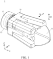
- FIG. 1 is a perspective view of an expandable spinal implant in accordance with the first embodiment of the disclosure
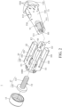
- FIG. 2 is an exploded view of the expandable spinal implant in FIG. 1
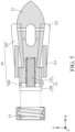
- FIG. 3 is an exploded and cross-sectional view of a flexible body and an expander component of the expandable spinal implant in FIG. 1 .
- an expandable spinal implant 1 is provided.
- the expandable spinal implant 1 is configured to be inserted between two vertebrae (not shown in figures).
- the expandable spinal implant 1 includes a flexible body 10, an expander component 11, a fastener 12 and an anti-reverse mechanism 13.
- the expander component 11 may include a metallic material such as stainless steel (e.g., 316L, 404, 420J2, or 17-4), titanium alloy (e.g., Ti 6 Al 4 V), cobalt-chromium alloy, iron-based alloy, magnesium-based alloy, nickel alloy (e.g., Inconel 718), or aluminum alloy (e.g., AlSi 10 Mg). Furthermore, the expander component 11 may be manufactured through various processing methods such as casting, metal stamping, computer numerical control (CNC) machining, and additive manufacturing.
- CNC computer numerical control
- the flexible body 10 may include a polymeric material such as carbon fiber-reinforced polymer (CFRP), polyetheretherketone (PEEK), or polyetherketoneketone, (PEKK). Furthermore, the flexible body 10 may be manufactured through various processing methods such as injection molding, extrusion molding, membrane pressing, hot pressing, blow molding, moulding, winding molding, prepreg stacking, transfer molding, foaming, casting, and additive manufacturing.
- CFRP carbon fiber-reinforced polymer
- PEEK polyetheretherketone
- PEKK polyetherketoneketone
- the flexible body 10 includes a base portion 100, four flexible arms 101 and four rigid side plates 102. Each of the flexible arms 101 has a fixed end E1 and a free end E2. The fixed ends E1 of the flexible arms 101 are connected to the base portion 100, and the flexible arms 101 collectively surround an installation space S1.
- the base portion 100 of the flexible body 10 has two guiding grooves S2 connected to the installation space S1, and the two guiding grooves S2 extend in a direction parallel to a central axis CL of the expander component 11.
- the rigid side plates 102 are connected to the base portion 100, each of the rigid side plates 102 is located between adjacent two of the flexible arms 101, and a length of each of the rigid side plates 102 is smaller than a length of each of the flexible arms 101; therefore, by incorporating the rigid side plates 102 in the flexible body 10, the structural strength of the flexible body 10 is enhanced.
- the rigid side plates 102 are optional, and the present disclosure is not limited thereto. In some embodiments of the present disclosure, the flexible body may not have a rigid side plate.
- the expander component 11 is partially disposed in the installation space S1 of the flexible body 10 and exerts pressure on the free ends E2 of the flexible arms 101, such that the free ends E2 are moved in directions away from one another.
- the expander component 11 may include a main portion 110, two guiding protrusions 111 and an operation portion 119.
- An outer diameter of the main portion 110 progressively increases in a direction away from the base portion 100, such that the main portion 110 has an inclined outer surface TS1, and an angle ⁇ 1 between the inclined outer surface TS1 and the central axis CL of the expander component 11 may be between 7.0 degrees and 8.5 degrees, inclusive.
- the main portion 110 may have a screw hole H1 facing the base portion 100, and the screw hole H1 has an internal thread T1 on an inner wall thereof.
- the two guiding protrusions 111 are connected to one side of the main portion 110 located closer to the base portion 100, and the two guiding protrusions 111 are inserted into the two guiding grooves S2 of the base portion 100.
- the operation portion 119 is connected to another side of the main portion 110 located farther away from the base portion 100, and the operation portion 119 sticks out of the installation space S1 of the flexible body 10, allowing medical personnel or others to easily grip the operating portion 119 to assemble the expander component 11 into the installation space S1 of the flexible body 10.
- each of the free ends E2 of the flexible arms 101 is pushed in a direction away from the central axis CL by the inclined outer surface TS1 of the main portion 110 of the expander component 11, such that the free ends E2 expand both in a horizontal direction D1 and in a vertical direction D2 perpendicular to the horizontal direction D1.
- each of the flexible arms 101 may have a chamfered contact surface CS facing the installation space S1 and in physical contact with the inclined outer surface TS1 of the main portion 110 of the expander component 11, so that the expander component 11 exerts pressure on the chamfered contact surfaces CS of the flexible arms 101, ensuring that the flexible arms 101 expand in desired directions, respectively.
- the chamfered contact surfaces CS of the flexible arms 101 may also function as guides, facilitating linear movement of the expander component 11 within the installation space S1 along a direction parallel to the central axis CL when assembling the expander component 11.
- the expander component 11 can be guided to move linearly within the installation space S1 of the flexible body 10, and unexpected rotation of the expander component 11 within the installation space S1 can be prevented.
- the expander component 11 may have a through-hole structure 112 and a plurality of bone-filling cavities FH1.
- the through-hole structure 112 penetrates through the main portion 110, and the bone-filling cavities FH1 are located on the main portion 110 and connected to the through-hole structure 112.
- a porosity of the main portion 110 may be 40%, enhancing the ingrowth of bone cells.
- the fastener 12 includes a head portion 120 and a screw portion 121 connected to each other.
- the head portion 120 and the expander component 11 are located on two opposite sides of the base portion 100, respectively, the screw portion 121 has an external thread T2 on a surface thereof, and the screw portion 121 is disposed through the base portion 100 and screwed into the screw hole H1 of the main portion 110 of the expander component 11.
- the external thread T2 of the screw portion 121 and the internal thread T1 of the screw hole H1 are engaged with each other, such that the screw portion 121 is screwed into the expander component 11.
- the head portion 120 of the fastener 12 may be in contact with the base portion 100.
- the anti-reverse mechanism 13 is fixed to the base portion 100, and the anti-reverse mechanism 13 and the expander component 11 are located on the two opposite sides of the base portion 100, respectively, so that the anti-reverse mechanism 13 blocks one side of the head portion 120 of the fastener 12 located away from the expander component 11.
- the base portion 100 has a fixation protrusion 1000 protruding in a direction away from the flexible arms 101, and the fixation protrusion 1000 has an external thread (not numbered).
- the anti-reverse mechanism 13 is, for example, a cap with an internal thread (not numbered), and the anti-reverse mechanism 13 is secured to the base portion 100 by engaging its internal thread with the external thread of the fixation protrusion 1000, such that the anti-reverse mechanism 13 blocks one side of the head portion 120 of the fastener 12 away from the expander component 11, and the head portion 120 of the fastener 12 is clamped by the anti-reverse mechanism 13 and the base portion 100.
- This arrangement prevents unexpected disengagement of the fastener 12 from the base portion 100, and thus prevents unexpected separation of the fastener 12 from the expander component 11, thereby ensuring a strong and stable assembly over prolonged use. It is noted that the present disclosure is not limited to the specific method described above for securing the anti-reverse mechanism to the base portion.
- FIG. 4 to FIG. 6 show cross-sectional views of an assembly process of the expandable spinal implant in FIG. 1 .
- Last secure the anti-reverse mechanism 13 to the base portion 100, so that at least a part of the anti-reverse mechanism 13 blocks one side of the head portion 120 of the fastener 12 located away from the expander component 11.
- an outer surface of the flexible body 10 may have a porous structure. Therefore, the bonding strength between the expandable spinal implant 1 and the vertebrae can be increased.
- the porous structure of the flexible body 10 and the through-hole structure 112 and the bone-filling cavities FH1 of the expander component 11 provide space for bone filling, enhancing the capability for bone cell ingrowth and bone induction, and improving bone integration effectiveness.
- the fastener 12 may be, for example, a M3 screw, and the internal thread T1 of the screw hole H1 of the expander component 11 may be, for example, a M3 thread corresponding thereto, but the present disclosure is not limited thereto.
- a length BL1 of the flexible body 10 in the horizontal direction D1 is, for example, 10 mm.
- a maximum length ML1 of the flexible body 10 in the horizontal direction D1 may range, for example, between 11.41 mm and 15.62 mm (inclusive). Therefore, an expansion ratio of the flexible body 10 in the horizontal direction D1 can be calculated to be 14.1% to 56.2%.
- expandable spinal implants in various embodiments of the present disclosure can be individually tailored for the expansion adjustment between vertebrae to specific heights and angles, allowing for the correction of the physiological curvature of the spine and reducing the probability of sinking of the expandable spinal implant.
- FIG. 7 is a front view of the expandable spinal implant of FIG. 1 .
- the maximum length ML1 of the flexible body 10 in the horizontal direction D1 is different from a maximum length ML2 of the flexible body 10 in the vertical direction D2, but the present disclosure is not limited thereto.
- the maximum length of the flexible body in the horizontal direction may be the same as the maximum length of the flexible body in the vertical direction.
- a shape of the flexible body 10 is a rectangular column, but the present disclosure is not limited thereto. In other embodiments, the shape of the flexible body may be cylindrical.
- FIG. 8 is a perspective view of a flexible body of an expandable spinal implant in accordance with the second embodiment of the disclosure.
- an expandable spinal implant is similar to the expandable spinal implant 1 in FIG. 1 as described above.
- the same reference numerals indicate the same components, and functions and effects provided by those components are the same as described above, so an explanation in this regard will not be provided again.
- each of flexible arms 101b of a flexible body 10b has a plurality of cut grooves R1 on an inner surface NS 1 thereof located adjacent to the installation space S1, where the cut grooves R1 are inclined with respect to the inner surface NS1, and the cut grooves R1 slantingly extend from the inner surface NS1 in a direction towards a base portion 100b.
- an angle ⁇ 2 between an extension direction of the cut grooves R1 and the central axis CL may range, for example, between 35 degrees and 55 degrees (inclusive), and a depth DP1 of each of the cut grooves R1 may be, for example, 51% to 80% (inclusive) of a thickness TH1 of each of the flexible arms 101b.
- an opening width W1 of each of the cut grooves R1 may be, for example, 0.2 mm.
- FIG. 9 is a perspective view of a flexible body of an expandable spinal implant in accordance with the third embodiment of the disclosure.
- an expandable spinal implant is similar to the expandable spinal implant 1 in FIG. 1 as described above.
- the same reference numerals indicate the same components, and functions and effects provided by those components are the same as described above, so an explanation in this regard will not be provided again.
- each of flexible arms 101c of a flexible body 10c has a plurality of cut grooves R1 on an inner surface NS 1 thereof located adjacent to the installation space S1, where the cut grooves R1 are inclined with respect to the inner surface NS1, and the cut grooves R1 slantingly extend from the inner surface NS1 in a direction away from a base portion 100c.
- an angle ⁇ 2 between an extension direction of the cut grooves R1 and the central axis CL may range, for example, between 35 degrees and 55 degrees (inclusive), and a depth DP1 of each of the cut grooves R1 may be, for example, 51% to 80% (inclusive) of a thickness TH1 of each of the flexible arms 101c.
- an opening width W1 of each of the cut grooves R1 may be, for example, 0.2 mm.
- the quantity of the flexible arms of the flexible body is four, but the present disclosure is not limited to the quantity of the flexible arms.
- FIG. 10 is a perspective view of a flexible body of an expandable spinal implant in accordance with the fourth embodiment of the disclosure.
- an expandable spinal implant is similar to the expandable spinal implant 1 in FIG. 1 as described above.
- the same reference numerals indicate the same components, and functions and effects provided by those components are the same as described above, so an explanation in this regard will not be provided again.
- the quantity of the flexible arms 101d of the flexible body 10d is eight.
- the flexible arms expand in multiple directions, increasing the contact area between the expandable spinal implant and the vertebrae, and the overall structural strength can be enhanced, thereby preventing the expandable spinal implant from sinking due to compression from the vertebrae.
- the anti-reverse mechanism blocking the fastener unexpected disengagement of the fastener from the base portion of the flexible body can be prevented, thereby preventing unexpected separation of the fastener from the expander component.
Landscapes
- Health & Medical Sciences (AREA)
- Engineering & Computer Science (AREA)
- Biomedical Technology (AREA)
- Orthopedic Medicine & Surgery (AREA)
- Neurology (AREA)
- Transplantation (AREA)
- Heart & Thoracic Surgery (AREA)
- Oral & Maxillofacial Surgery (AREA)
- Cardiology (AREA)
- Vascular Medicine (AREA)
- Life Sciences & Earth Sciences (AREA)
- Animal Behavior & Ethology (AREA)
- General Health & Medical Sciences (AREA)
- Public Health (AREA)
- Veterinary Medicine (AREA)
- Physical Education & Sports Medicine (AREA)
- Prostheses (AREA)
Abstract
Description
- This disclosure relates to a spinal implant.
- The intervertebral disc, positioned between the vertebrae, plays a pivotal role in distributing forces throughout the spine. It comprises two primary components which are the outer annulus fibrosus and the inner nucleus pulposus. The outer annulus fibrosus consists of multiple layers of collagen fibers, while the inner nucleus pulposus is a gel-like substance. This structural combination, with the harder outer layer surrounding the softer inner core, makes the intervertebral disc an effective weight-bearing and shock-absorbing mechanism. However, in the event of injury, the intervertebral disc may become a potential source of discomfort and pain.
- One embodiment of the disclosure provides an expandable spinal implant configured to be inserted between two vertebrae. The expandable spinal implant includes a flexible body, an expander component, a fastener and an anti-reverse mechanism. The flexible body includes a base portion and a plurality of flexible arms. Each of the flexible arms has a fixed end and a free end opposite to each other, the fixed ends of the flexible arms are connected to the base portion, and the flexible arms collectively surround an installation space. The expander component is partially disposed in the installation space and exerts pressure on the free ends of the flexible arms, such that the free ends are moved in directions away from one another. The fastener includes a head portion and a screw portion connected to each other. The head portion and the expander component are located on two opposite sides of the base portion, respectively. The screw portion is disposed through the base portion and screwed into the expander component. The anti-reverse mechanism is fixed to the base portion. The anti-reverse mechanism and the expander component are located on the two opposite sides of the base portion, respectively. The anti-reverse mechanism blocks one side of the head portion of the fastener located away from the expander component.
- The present disclosure will become more fully understood from the detailed description given hereinbelow and the accompanying drawings which are given by way of illustration only and thus are not limitative of the present disclosure and wherein:
-
FIG. 1 is a perspective view of an expandable spinal implant in accordance with the first embodiment of the disclosure; -
FIG. 2 is an exploded view of the expandable spinal implant inFIG. 1 ; -
FIG. 3 is an exploded and cross-sectional view of a flexible body and an expander component of the expandable spinal implant inFIG. 1 ; -
FIG. 4 to FIG. 6 show cross-sectional views of an assembly process of the expandable spinal implant inFIG. 1 ; -
FIG. 7 is a front view of the expandable spinal implant ofFIG. 1 ; -
FIG. 8 is a perspective view of a flexible body of an expandable spinal implant in accordance with the second embodiment of the disclosure; -
FIG. 9 is a perspective view of a flexible body of an expandable spinal implant in accordance with the third embodiment of the disclosure; and -
FIG. 10 is a perspective view of a flexible body of an expandable spinal implant in accordance with the fourth embodiment of the disclosure. - In the following detailed description, for purpose of explanation, numerous specific details are set forth in order to provide a thorough understanding of the disclosed embodiments. It will be apparent, however, that one or more embodiments may be practiced without these specific details. In other instances, well-known structures and devices are schematically shown in order to simplify the drawing.
- Please refer to
FIG. 1 to FIG. 3 .FIG. 1 is a perspective view of an expandable spinal implant in accordance with the first embodiment of the disclosure,FIG. 2 is an exploded view of the expandable spinal implant inFIG. 1 , andFIG. 3 is an exploded and cross-sectional view of a flexible body and an expander component of the expandable spinal implant inFIG. 1 . - In this embodiment, an expandable
spinal implant 1 is provided. The expandablespinal implant 1 is configured to be inserted between two vertebrae (not shown in figures). The expandablespinal implant 1 includes aflexible body 10, anexpander component 11, afastener 12 and ananti-reverse mechanism 13. - The
expander component 11 may include a metallic material such as stainless steel (e.g., 316L, 404, 420J2, or 17-4), titanium alloy (e.g., Ti6Al4V), cobalt-chromium alloy, iron-based alloy, magnesium-based alloy, nickel alloy (e.g., Inconel 718), or aluminum alloy (e.g., AlSi10Mg). Furthermore, theexpander component 11 may be manufactured through various processing methods such as casting, metal stamping, computer numerical control (CNC) machining, and additive manufacturing. - The
flexible body 10 may include a polymeric material such as carbon fiber-reinforced polymer (CFRP), polyetheretherketone (PEEK), or polyetherketoneketone, (PEKK). Furthermore, theflexible body 10 may be manufactured through various processing methods such as injection molding, extrusion molding, membrane pressing, hot pressing, blow molding, moulding, winding molding, prepreg stacking, transfer molding, foaming, casting, and additive manufacturing. - The
flexible body 10 includes abase portion 100, fourflexible arms 101 and fourrigid side plates 102. Each of theflexible arms 101 has a fixed end E1 and a free end E2. The fixed ends E1 of theflexible arms 101 are connected to thebase portion 100, and theflexible arms 101 collectively surround an installation space S1. Thebase portion 100 of theflexible body 10 has two guiding grooves S2 connected to the installation space S1, and the two guiding grooves S2 extend in a direction parallel to a central axis CL of theexpander component 11. Therigid side plates 102 are connected to thebase portion 100, each of therigid side plates 102 is located between adjacent two of theflexible arms 101, and a length of each of therigid side plates 102 is smaller than a length of each of theflexible arms 101; therefore, by incorporating therigid side plates 102 in theflexible body 10, the structural strength of theflexible body 10 is enhanced. However, therigid side plates 102 are optional, and the present disclosure is not limited thereto. In some embodiments of the present disclosure, the flexible body may not have a rigid side plate. - The
expander component 11 is partially disposed in the installation space S1 of theflexible body 10 and exerts pressure on the free ends E2 of theflexible arms 101, such that the free ends E2 are moved in directions away from one another. In detail, theexpander component 11 may include amain portion 110, two guidingprotrusions 111 and anoperation portion 119. An outer diameter of themain portion 110 progressively increases in a direction away from thebase portion 100, such that themain portion 110 has an inclined outer surface TS1, and an angle θ1 between the inclined outer surface TS1 and the central axis CL of theexpander component 11 may be between 7.0 degrees and 8.5 degrees, inclusive. Additionally, themain portion 110 may have a screw hole H1 facing thebase portion 100, and the screw hole H1 has an internal thread T1 on an inner wall thereof. The two guidingprotrusions 111 are connected to one side of themain portion 110 located closer to thebase portion 100, and the two guidingprotrusions 111 are inserted into the two guiding grooves S2 of thebase portion 100. Theoperation portion 119 is connected to another side of themain portion 110 located farther away from thebase portion 100, and theoperation portion 119 sticks out of the installation space S1 of theflexible body 10, allowing medical personnel or others to easily grip theoperating portion 119 to assemble theexpander component 11 into the installation space S1 of theflexible body 10. Moreover, each of the free ends E2 of theflexible arms 101 is pushed in a direction away from the central axis CL by the inclined outer surface TS1 of themain portion 110 of theexpander component 11, such that the free ends E2 expand both in a horizontal direction D1 and in a vertical direction D2 perpendicular to the horizontal direction D1. In addition, each of theflexible arms 101 may have a chamfered contact surface CS facing the installation space S1 and in physical contact with the inclined outer surface TS1 of themain portion 110 of theexpander component 11, so that theexpander component 11 exerts pressure on the chamfered contact surfaces CS of theflexible arms 101, ensuring that theflexible arms 101 expand in desired directions, respectively. Besides, the chamfered contact surfaces CS of theflexible arms 101 may also function as guides, facilitating linear movement of theexpander component 11 within the installation space S1 along a direction parallel to the central axis CL when assembling theexpander component 11. - In this embodiment, by the coordination between the guiding grooves S2 of the
base portion 100 of theflexible body 10 and the guidingprotrusions 111 of theexpander component 11, when theexpander component 11 is assembled onto theflexible body 10, theexpander component 11 can be guided to move linearly within the installation space S1 of theflexible body 10, and unexpected rotation of theexpander component 11 within the installation space S1 can be prevented. - Furthermore, the
expander component 11 may have a through-hole structure 112 and a plurality of bone-filling cavities FH1. The through-hole structure 112 penetrates through themain portion 110, and the bone-filling cavities FH1 are located on themain portion 110 and connected to the through-hole structure 112. Through this arrangement, a porosity of themain portion 110 may be 40%, enhancing the ingrowth of bone cells. - The
fastener 12 includes ahead portion 120 and ascrew portion 121 connected to each other. Thehead portion 120 and theexpander component 11 are located on two opposite sides of thebase portion 100, respectively, thescrew portion 121 has an external thread T2 on a surface thereof, and thescrew portion 121 is disposed through thebase portion 100 and screwed into the screw hole H1 of themain portion 110 of theexpander component 11. Moreover, the external thread T2 of thescrew portion 121 and the internal thread T1 of the screw hole H1 are engaged with each other, such that thescrew portion 121 is screwed into theexpander component 11. Furthermore, thehead portion 120 of thefastener 12 may be in contact with thebase portion 100. - The
anti-reverse mechanism 13 is fixed to thebase portion 100, and theanti-reverse mechanism 13 and theexpander component 11 are located on the two opposite sides of thebase portion 100, respectively, so that theanti-reverse mechanism 13 blocks one side of thehead portion 120 of thefastener 12 located away from theexpander component 11. In this embodiment, thebase portion 100 has afixation protrusion 1000 protruding in a direction away from theflexible arms 101, and thefixation protrusion 1000 has an external thread (not numbered). Theanti-reverse mechanism 13 is, for example, a cap with an internal thread (not numbered), and theanti-reverse mechanism 13 is secured to thebase portion 100 by engaging its internal thread with the external thread of thefixation protrusion 1000, such that theanti-reverse mechanism 13 blocks one side of thehead portion 120 of thefastener 12 away from theexpander component 11, and thehead portion 120 of thefastener 12 is clamped by theanti-reverse mechanism 13 and thebase portion 100. This arrangement prevents unexpected disengagement of thefastener 12 from thebase portion 100, and thus prevents unexpected separation of thefastener 12 from theexpander component 11, thereby ensuring a strong and stable assembly over prolonged use. It is noted that the present disclosure is not limited to the specific method described above for securing the anti-reverse mechanism to the base portion. - The assembly process of the expandable
spinal implant 1 is further illustrated below. Please refer toFIG. 4 to FIG. 6 , which show cross-sectional views of an assembly process of the expandable spinal implant inFIG. 1 . - As shown in
FIG. 4 , first, place theexpander component 11 partially into the installation space S1 of theflexible body 10 and position theexpander component 11 in a pre-assembled position, and ensure that the two guidingprotrusions 111 of theexpander component 11 correspond to the two guiding grooves S2 of thebase portion 100. - Then, insert the
screw portion 121 of thefastener 12 through thebase portion 100 and into the screw hole H1 of themain portion 110 of theexpander component 11, and rotate thefastener 12 to drive theexpander component 11 to move linearly by engaging the external thread T2 of thescrew portion 121 with the internal thread T1 of the screw hole H1. Continue this rotation until thefastener 12 is securely tightened against theexpander component 11, positioning theexpander component 11 in an assembled position (as shown inFIG. 5 ). At this point, theflexible arms 101 of theflexible body 10 expand in multiple directions in both the horizontal direction D1 and the vertical direction D2 due to the pushing force from theexpander component 11, making the expandablespinal implant 1 exhibit a wedge shape. Specifically, an outer diameter at the free ends E2 of theflexible arms 101 can be greater than an outer diameter at the fixed ends E1 of theflexible arms 101, enabling the correction of the physiological curvature of the spine. - Last, as shown in
FIG. 6 , secure theanti-reverse mechanism 13 to thebase portion 100, so that at least a part of theanti-reverse mechanism 13 blocks one side of thehead portion 120 of thefastener 12 located away from theexpander component 11. - In this embodiment, an outer surface of the
flexible body 10 may have a porous structure. Therefore, the bonding strength between the expandablespinal implant 1 and the vertebrae can be increased. In addition, the porous structure of theflexible body 10 and the through-hole structure 112 and the bone-filling cavities FH1 of theexpander component 11 provide space for bone filling, enhancing the capability for bone cell ingrowth and bone induction, and improving bone integration effectiveness. - In this embodiment, the
fastener 12 may be, for example, a M3 screw, and the internal thread T1 of the screw hole H1 of theexpander component 11 may be, for example, a M3 thread corresponding thereto, but the present disclosure is not limited thereto. - As shown in
FIG. 3 , before the expansion of theflexible arms 101, a length BL1 of theflexible body 10 in the horizontal direction D1 is, for example, 10 mm. As shown inFIG. 6 , after the expansion of theflexible arms 101, according to various angle configurations where an angle θ1 between the inclined outer surface TS1 of themain portion 110 of theexpander component 11 and the central axis CL of theexpander component 11 can range between 7.0 degrees and 8.5 degrees (inclusive), a maximum length ML1 of theflexible body 10 in the horizontal direction D1 may range, for example, between 11.41 mm and 15.62 mm (inclusive). Therefore, an expansion ratio of theflexible body 10 in the horizontal direction D1 can be calculated to be 14.1% to 56.2%. Through the specified design ranges of angles and expansion ratios as mentioned above, expandable spinal implants in various embodiments of the present disclosure can be individually tailored for the expansion adjustment between vertebrae to specific heights and angles, allowing for the correction of the physiological curvature of the spine and reducing the probability of sinking of the expandable spinal implant. - Please refer to
FIG. 7 , which is a front view of the expandable spinal implant ofFIG. 1 . In this embodiment, after the expansion of theflexible arms 101, the maximum length ML1 of theflexible body 10 in the horizontal direction D1 is different from a maximum length ML2 of theflexible body 10 in the vertical direction D2, but the present disclosure is not limited thereto. In other embodiments, the maximum length of the flexible body in the horizontal direction may be the same as the maximum length of the flexible body in the vertical direction. Furthermore, in this embodiment, a shape of theflexible body 10 is a rectangular column, but the present disclosure is not limited thereto. In other embodiments, the shape of the flexible body may be cylindrical. - Please refer to
FIG. 8 , which is a perspective view of a flexible body of an expandable spinal implant in accordance with the second embodiment of the disclosure. In this embodiment (corresponding toFIG. 8 ), an expandable spinal implant is similar to the expandablespinal implant 1 inFIG. 1 as described above. The same reference numerals indicate the same components, and functions and effects provided by those components are the same as described above, so an explanation in this regard will not be provided again. - In this embodiment, each of
flexible arms 101b of aflexible body 10b has a plurality of cut grooves R1 on aninner surface NS 1 thereof located adjacent to the installation space S1, where the cut grooves R1 are inclined with respect to the inner surface NS1, and the cut grooves R1 slantingly extend from the inner surface NS1 in a direction towards abase portion 100b. Moreover, before the expansion of theflexible arms 101b, an angle θ2 between an extension direction of the cut grooves R1 and the central axis CL may range, for example, between 35 degrees and 55 degrees (inclusive), and a depth DP1 of each of the cut grooves R1 may be, for example, 51% to 80% (inclusive) of a thickness TH1 of each of theflexible arms 101b. In addition, an opening width W1 of each of the cut grooves R1 may be, for example, 0.2 mm. - By incorporating the cut grooves R1 inclined in a forward direction on the
flexible arms 101b, a friction between theflexible arms 101b and an expander component can be increased, which facilitates easier expansion of theflexible arms 101b of theflexible body 10b, and the expander component is less prone to extracting from the installation space S1 of theflexible body 10b. Therefore, it is advantageous for securing the expander component in place. - Please refer to
FIG. 9 , which is a perspective view of a flexible body of an expandable spinal implant in accordance with the third embodiment of the disclosure. In this embodiment (corresponding toFIG. 9 ), an expandable spinal implant is similar to the expandablespinal implant 1 inFIG. 1 as described above. The same reference numerals indicate the same components, and functions and effects provided by those components are the same as described above, so an explanation in this regard will not be provided again. - In this embodiment, each of
flexible arms 101c of aflexible body 10c has a plurality of cut grooves R1 on aninner surface NS 1 thereof located adjacent to the installation space S1, where the cut grooves R1 are inclined with respect to the inner surface NS1, and the cut grooves R1 slantingly extend from the inner surface NS1 in a direction away from abase portion 100c. Moreover, before the expansion of theflexible arms 101c, an angle θ2 between an extension direction of the cut grooves R1 and the central axis CL may range, for example, between 35 degrees and 55 degrees (inclusive), and a depth DP1 of each of the cut grooves R1 may be, for example, 51% to 80% (inclusive) of a thickness TH1 of each of theflexible arms 101c. In addition, an opening width W1 of each of the cut grooves R1 may be, for example, 0.2 mm. - By incorporating the cut grooves R1 inclined in a reverse direction on the
flexible arms 101c, a friction between theflexible arms 101c and an expander component can be increased. - In the above embodiments, the quantity of the flexible arms of the flexible body is four, but the present disclosure is not limited to the quantity of the flexible arms. For example, please refer to
FIG. 10 , which is a perspective view of a flexible body of an expandable spinal implant in accordance with the fourth embodiment of the disclosure. In this embodiment (corresponding toFIG. 10 ), an expandable spinal implant is similar to the expandablespinal implant 1 inFIG. 1 as described above. The same reference numerals indicate the same components, and functions and effects provided by those components are the same as described above, so an explanation in this regard will not be provided again. In this embodiment, the quantity of theflexible arms 101d of theflexible body 10d is eight. - In view of the above description, by inserting the expander component between the flexible arms of the flexible body, the flexible arms expand in multiple directions, increasing the contact area between the expandable spinal implant and the vertebrae, and the overall structural strength can be enhanced, thereby preventing the expandable spinal implant from sinking due to compression from the vertebrae. Additionally, by the anti-reverse mechanism blocking the fastener, unexpected disengagement of the fastener from the base portion of the flexible body can be prevented, thereby preventing unexpected separation of the fastener from the expander component.
- It will be apparent to those skilled in the art that various modifications and variations can be made to the disclosed embodiments. It is intended that the specification and examples be considered as exemplars only, with a true scope of the disclosure being indicated by the following claims and their equivalents.
Claims (17)
- An expandable spinal implant (1), configured to be inserted between two vertebrae, comprising:a flexible body (10) comprising a base portion (100) and a plurality of flexible arms (101), each of the plurality of flexible arms (101) having a fixed end (E1) and a free end (E2) opposite to each other, the fixed ends (E1) of the plurality of flexible arms (101) connected to the base portion (100), and the plurality of flexible arms (101) collectively surrounding an installation space (S1);an expander component (11) partially disposed in the installation space (S1) and exerting pressure on the free ends (E2) of the plurality of flexible arms (101), such that the free ends (E2) are moved in directions away from one another;a fastener (12) comprising a head portion (120) and a screw portion (121) connected to each other, the head portion (120) and the expander component (11) located on two opposite sides of the base portion (100), respectively, and the screw portion (121) disposed through the base portion (100) and screwed into the expander component (11); andan anti-reverse mechanism (13) fixed to the base portion (100), the anti-reverse mechanism (13) and the expander component (11) located on the two opposite sides of the base portion (100), respectively, and the anti-reverse mechanism (13) blocking one side of the head portion (120) of the fastener (12) located away from the expander component (11).
- The expandable spinal implant (1) according to claim 1, wherein the expander component (11) has a screw hole (H1) facing the base portion (100), the screw hole (H1) has an internal thread (T1) on an inner wall thereof, the screw portion (121) of the fastener (12) has an external thread (T2) on a surface thereof, the screw portion (121) is inserted into the screw hole (H1), and the external thread (T2) and the internal thread (T1) are engaged with each other.
- The expandable spinal implant (1) according to claim 1, wherein the free ends (E2) of the plurality of flexible arms (101) expand both in a horizontal direction (D1) and in a vertical direction (D2) perpendicular to the horizontal direction (D1).
- The expandable spinal implant (1) according to claim 1, wherein the flexible body (10) has a porous structure on an outer surface thereof.
- The expandable spinal implant (1) according to claim 1, wherein each of the plurality of flexible arms (101b, 101c) has a plurality of cut grooves (R1) on an inner surface (NS1) thereof located adjacent to the installation space (S1).
- The expandable spinal implant (1) according to claim 5, wherein the plurality of cut grooves (R1) are inclined with respect to the inner surface (NS1), and the plurality of cut grooves (R1) slantingly extend from the inner surface in a direction towards the base portion (100b).
- The expandable spinal implant (1) according to claim 5, wherein the plurality of cut grooves (R1) are inclined with respect to the inner surface (NS1), and the plurality of cut grooves (R1) slanting extend from the inner surface (NS1) in a direction away from the base portion (100c).
- The expandable spinal implant (1) according to claim 5, wherein an angle (θ2) between an extension direction of the plurality of cut grooves (R1) and a central axis (CL) of the expander component (11) is between 35 degrees and 55 degrees, inclusive.
- The expandable spinal implant (1) according to claim 5, wherein a depth (DP1) of each of the plurality of cut grooves (R1) is 51% to 80%, inclusive, of a thickness (TH1) of each of the plurality of flexible arms (101b, 101c), and an opening width (W1) of each of the plurality of cut grooves (R1) is 0.2 mm.
- The expandable spinal implant (1) according to claim 1, wherein the base portion (100) of the flexible body (10) has a guiding groove (S2) connected to the installation space (S1), the expander component (11) comprises a main portion (110) and a guiding protrusion (111), the guiding protrusion (111) is connected to the main portion (110), and the guiding protrusion (111) is inserted into the guiding groove (S2).
- The expandable spinal implant (1) according to claim 1, wherein the flexible body (10) further comprises a plurality of rigid side plates (102), the plurality of rigid side plates (102) are connected to the base portion (100), and each of the plurality of rigid side plates (102) is located between adjacent two of the plurality of flexible arms (101).
- The expandable spinal implant (1) according to claim 1, wherein a quantity of the plurality of flexible arms (101, 101d) is four or eight.
- The expandable spinal implant (1) according to claim 1, wherein the expander component (11) comprises a main portion (110), and an outer diameter of the main portion (110) progressively increases in a direction away from the base portion (100).
- The expandable spinal implant (1) according to claim 1, wherein the expander component (11) comprises a main portion (110), the expander component (11) has a through-hole structure (112) and a plurality of bone-filling cavities (FH1), the through-hole structure (112) penetrates through the main portion (110), and the plurality of bone-filling cavities (FH1) are located on the main portion (110) and connected to the through-hole structure (112).
- The expandable spinal implant (1) according to claim 14, wherein a porosity of the main portion (110) is 40%.
- The expandable spinal implant (1) according to claim 1, wherein the expander component (11) comprises a main portion (110), the main portion (110) has an inclined outer surface (TS1), and an angle (θ1) between the inclined outer surface (TS1) and a central axis (CL) of the expander component (11) is between 7.0 degrees and 8.5 degrees, inclusive.
- The expandable spinal implant (1) according to claim 1, wherein the expander component (11) comprises a metallic material, and the flexible body (10) comprises a polymeric material.
Applications Claiming Priority (1)
| Application Number | Priority Date | Filing Date | Title |
|---|---|---|---|
| TW112146889A TWI872838B (en) | 2023-12-01 | 2023-12-01 | Expandable spinal implant |
Publications (2)
| Publication Number | Publication Date |
|---|---|
| EP4563124A1 true EP4563124A1 (en) | 2025-06-04 |
| EP4563124B1 EP4563124B1 (en) | 2026-03-11 |
Family
ID=89473853
Family Applications (1)
| Application Number | Title | Priority Date | Filing Date |
|---|---|---|---|
| EP23220316.6A Active EP4563124B1 (en) | 2023-12-01 | 2023-12-27 | Expandable spinal implant |
Country Status (3)
| Country | Link |
|---|---|
| US (1) | US12433758B2 (en) |
| EP (1) | EP4563124B1 (en) |
| TW (1) | TWI872838B (en) |
Families Citing this family (1)
| Publication number | Priority date | Publication date | Assignee | Title |
|---|---|---|---|---|
| CN121587888B (en) * | 2026-01-28 | 2026-04-21 | 北京爱康宜诚医疗器材有限公司 | Vertebral prosthesis |
Citations (8)
| Publication number | Priority date | Publication date | Assignee | Title |
|---|---|---|---|---|
| US20020143401A1 (en) * | 2001-03-27 | 2002-10-03 | Michelson Gary K. | Radially expanding interbody spinal fusion implants, instrumentation, and methods of insertion |
| US20090099568A1 (en) * | 2007-08-07 | 2009-04-16 | David Lowry | Device and method for variably adjusting intervertebral distraction and lordosis |
| US20140257486A1 (en) * | 2013-03-11 | 2014-09-11 | Stryker Spine | Expandable implant |
| US20150209152A1 (en) * | 2014-01-30 | 2015-07-30 | Titan Spine, Llc | Thermally activated shape memory spring assemblies for implant expansion |
| WO2018078450A1 (en) * | 2016-10-27 | 2018-05-03 | Ldr Medical | Expansible intervertebral implant |
| US11395745B2 (en) * | 2016-03-14 | 2022-07-26 | Wiltrom Co., Ltd. | Spinal implant structure and kit thereof |
| US20230277329A1 (en) * | 2022-03-01 | 2023-09-07 | Medos International Sarl | Stabilization Members For Expandable Intervertebral Implants, And Related Systems And Methods |
| US20230346569A1 (en) * | 2021-12-22 | 2023-11-02 | Ctl Biotec, Corporation | Expandable bi-dimensional interbody and method of manufacturing the same |
Family Cites Families (16)
| Publication number | Priority date | Publication date | Assignee | Title |
|---|---|---|---|---|
| US3941028A (en) * | 1975-03-06 | 1976-03-02 | The Eastern Company | Mine roof expansion anchor |
| US5390683A (en) * | 1991-02-22 | 1995-02-21 | Pisharodi; Madhavan | Spinal implantation methods utilizing a middle expandable implant |
| US5275512A (en) * | 1992-07-14 | 1994-01-04 | The Eastern Company | Mine roof expansion anchor and bail member therefor |
| US7722674B1 (en) | 2005-08-12 | 2010-05-25 | Innvotec Surgical Inc. | Linearly expanding spine cage for enhanced spinal fusion |
| EP2477578B1 (en) * | 2009-09-23 | 2015-08-19 | Zimmer Spine, Inc. | Composite implant |
| US10039650B2 (en) | 2013-03-15 | 2018-08-07 | In Queue Innovations, Llc | Expandable fusion cage system |
| US9421110B2 (en) | 2013-05-10 | 2016-08-23 | Sidewinder Medical Products Llc | Expandable spinal fusion cage |
| WO2016077610A1 (en) | 2014-11-12 | 2016-05-19 | Grotz Robert Thomas | Universally expanding cage |
| CN104323873A (en) * | 2014-11-18 | 2015-02-04 | 孙钢 | Minimally invasive adjustable interbody fusion cage for spondylolysis |
| US20170100255A1 (en) * | 2015-04-16 | 2017-04-13 | Expanding Orthopedics Inc. | Intervertebral cage for lateral approach |
| US9848996B2 (en) * | 2015-06-17 | 2017-12-26 | Globus Medical, Inc. | Variable lordotic interbody spacer |
| AT519915B1 (en) | 2017-05-11 | 2020-11-15 | Blum Gmbh Julius | Dowels for fastening hardware components |
| TW201912120A (en) * | 2017-09-04 | 2019-04-01 | 國立臺灣大學 | Ratchet type expandable intervertebral cage and operation tool thereof for greatly enhancing surgery convenience and enabling fast postoperative recovery |
| JP6820608B2 (en) * | 2018-11-09 | 2021-01-27 | Kisco株式会社 | Interbody cage |
| TWI720677B (en) | 2019-11-05 | 2021-03-01 | 台灣微創醫療器材股份有限公司 | Spinal implant structure |
| TWI736010B (en) * | 2019-11-08 | 2021-08-11 | 財團法人工業技術研究院 | Spinal intervertebral body fusion device |
-
2023
- 2023-12-01 TW TW112146889A patent/TWI872838B/en active
- 2023-12-26 US US18/396,331 patent/US12433758B2/en active Active
- 2023-12-27 EP EP23220316.6A patent/EP4563124B1/en active Active
Patent Citations (8)
| Publication number | Priority date | Publication date | Assignee | Title |
|---|---|---|---|---|
| US20020143401A1 (en) * | 2001-03-27 | 2002-10-03 | Michelson Gary K. | Radially expanding interbody spinal fusion implants, instrumentation, and methods of insertion |
| US20090099568A1 (en) * | 2007-08-07 | 2009-04-16 | David Lowry | Device and method for variably adjusting intervertebral distraction and lordosis |
| US20140257486A1 (en) * | 2013-03-11 | 2014-09-11 | Stryker Spine | Expandable implant |
| US20150209152A1 (en) * | 2014-01-30 | 2015-07-30 | Titan Spine, Llc | Thermally activated shape memory spring assemblies for implant expansion |
| US11395745B2 (en) * | 2016-03-14 | 2022-07-26 | Wiltrom Co., Ltd. | Spinal implant structure and kit thereof |
| WO2018078450A1 (en) * | 2016-10-27 | 2018-05-03 | Ldr Medical | Expansible intervertebral implant |
| US20230346569A1 (en) * | 2021-12-22 | 2023-11-02 | Ctl Biotec, Corporation | Expandable bi-dimensional interbody and method of manufacturing the same |
| US20230277329A1 (en) * | 2022-03-01 | 2023-09-07 | Medos International Sarl | Stabilization Members For Expandable Intervertebral Implants, And Related Systems And Methods |
Also Published As
| Publication number | Publication date |
|---|---|
| US20250177161A1 (en) | 2025-06-05 |
| TWI872838B (en) | 2025-02-11 |
| TW202523259A (en) | 2025-06-16 |
| US12433758B2 (en) | 2025-10-07 |
| EP4563124B1 (en) | 2026-03-11 |
Similar Documents
| Publication | Publication Date | Title |
|---|---|---|
| CA2243086C (en) | Screw thread implant | |
| EP3979951A1 (en) | Expandable implant assembly with compression features | |
| DK2584983T3 (en) | Bone plate and fastening system with a bone plate | |
| US20060122605A1 (en) | Translational plate with cover blocking system | |
| EP4563124B1 (en) | Expandable spinal implant | |
| US20200261121A1 (en) | Implant for bones or vertebrae with self-constrained flexibility | |
| EP1532950B1 (en) | Spinal disc prosthesis | |
| EP2796104B1 (en) | Fusion type intraspinal fixing screw | |
| EP1398008B1 (en) | Spacer for vertebrae or spinal discs | |
| US9232968B2 (en) | Polymeric pedicle rods and methods of manufacturing | |
| US20170020685A1 (en) | Fusion cage implant with lattice structure and grooves | |
| US20100042154A1 (en) | Flexible stabilization device including a rod and tool for manufacturing the rod | |
| AU2019244866A1 (en) | Locking structures for affixing bone anchors to a bone plate, and related systems and methods | |
| CN103919598B (en) | Spring wire type spine stabilizing device with deviation prevention | |
| WO2014059072A1 (en) | Bone plate and fusion cage interface | |
| WO2000047120A1 (en) | Bi-fed offset pitch bone screw | |
| WO2010030446A1 (en) | Offset vertebral rod connector | |
| AU2013272002A1 (en) | Orthopedic devices with a locking mechanism | |
| WO2009042512A1 (en) | Modular bone plate system | |
| US20110269103A1 (en) | Expandable implant | |
| EP2049029A2 (en) | Cervical plate system having an insertable rotating element | |
| DE102016124877B4 (en) | Intervertebral disc prosthesis and method for producing a disc prosthesis | |
| EP4223240B1 (en) | Bone anchor | |
| US20210369312A1 (en) | Variable angle bone plate system | |
| US20240225701A9 (en) | Assembleable artificial bone plate and artificial bone plate unit |
Legal Events
| Date | Code | Title | Description |
|---|---|---|---|
| PUAI | Public reference made under article 153(3) epc to a published international application that has entered the european phase |
Free format text: ORIGINAL CODE: 0009012 |
|
| STAA | Information on the status of an ep patent application or granted ep patent |
Free format text: STATUS: REQUEST FOR EXAMINATION WAS MADE |
|
| 17P | Request for examination filed |
Effective date: 20231227 |
|
| AK | Designated contracting states |
Kind code of ref document: A1 Designated state(s): AL AT BE BG CH CY CZ DE DK EE ES FI FR GB GR HR HU IE IS IT LI LT LU LV MC ME MK MT NL NO PL PT RO RS SE SI SK SM TR |
|
| GRAP | Despatch of communication of intention to grant a patent |
Free format text: ORIGINAL CODE: EPIDOSNIGR1 |
|
| STAA | Information on the status of an ep patent application or granted ep patent |
Free format text: STATUS: GRANT OF PATENT IS INTENDED |
|
| RIC1 | Information provided on ipc code assigned before grant |
Ipc: A61F 2/44 20060101AFI20250924BHEP Ipc: A61F 2/46 20060101ALI20250924BHEP |
|
| INTG | Intention to grant announced |
Effective date: 20251008 |
|
| GRAS | Grant fee paid |
Free format text: ORIGINAL CODE: EPIDOSNIGR3 |
|
| GRAA | (expected) grant |
Free format text: ORIGINAL CODE: 0009210 |
|
| STAA | Information on the status of an ep patent application or granted ep patent |
Free format text: STATUS: THE PATENT HAS BEEN GRANTED |
|
| AK | Designated contracting states |
Kind code of ref document: B1 Designated state(s): AL AT BE BG CH CY CZ DE DK EE ES FI FR GB GR HR HU IE IS IT LI LT LU LV MC ME MK MT NL NO PL PT RO RS SE SI SK SM TR |
|
| REG | Reference to a national code |
Ref country code: CH Ref legal event code: F10 Free format text: ST27 STATUS EVENT CODE: U-0-0-F10-F00 (AS PROVIDED BY THE NATIONAL OFFICE) Effective date: 20260311 Ref country code: GB Ref legal event code: FG4D |
|
| REG | Reference to a national code |
Ref country code: DE Ref legal event code: R096 Ref document number: 602023013320 Country of ref document: DE |
|
| REG | Reference to a national code |
Ref country code: IE Ref legal event code: FG4D |