EP4563123A1 - Patella trial implant and system comprising a patella trial implant and a drilling guide tool - Google Patents
Patella trial implant and system comprising a patella trial implant and a drilling guide tool Download PDFInfo
- Publication number
- EP4563123A1 EP4563123A1 EP23212949.4A EP23212949A EP4563123A1 EP 4563123 A1 EP4563123 A1 EP 4563123A1 EP 23212949 A EP23212949 A EP 23212949A EP 4563123 A1 EP4563123 A1 EP 4563123A1
- Authority
- EP
- European Patent Office
- Prior art keywords
- patella
- drilling
- guide
- trial implant
- tool
- Prior art date
- Legal status (The legal status is an assumption and is not a legal conclusion. Google has not performed a legal analysis and makes no representation as to the accuracy of the status listed.)
- Pending
Links
Images


Classifications
-
- A—HUMAN NECESSITIES
- A61—MEDICAL OR VETERINARY SCIENCE; HYGIENE
- A61F—FILTERS IMPLANTABLE INTO BLOOD VESSELS; PROSTHESES; DEVICES PROVIDING PATENCY TO, OR PREVENTING COLLAPSING OF, TUBULAR STRUCTURES OF THE BODY, e.g. STENTS; ORTHOPAEDIC, NURSING OR CONTRACEPTIVE DEVICES; FOMENTATION; TREATMENT OR PROTECTION OF EYES OR EARS; BANDAGES, DRESSINGS OR ABSORBENT PADS; FIRST-AID KITS
- A61F2/00—Filters implantable into blood vessels; Prostheses, i.e. artificial substitutes or replacements for parts of the body; Appliances for connecting them with the body; Devices providing patency to, or preventing collapsing of, tubular structures of the body, e.g. stents
- A61F2/02—Prostheses implantable into the body
- A61F2/30—Joints
- A61F2/46—Special tools for implanting artificial joints
- A61F2/4684—Trial or dummy prostheses
-
- A—HUMAN NECESSITIES
- A61—MEDICAL OR VETERINARY SCIENCE; HYGIENE
- A61B—DIAGNOSIS; SURGERY; IDENTIFICATION
- A61B17/00—Surgical instruments, devices or methods
- A61B17/16—Instruments for performing osteoclasis; Drills or chisels for bones; Trepans
- A61B17/1662—Instruments for performing osteoclasis; Drills or chisels for bones; Trepans for particular parts of the body
- A61B17/1675—Instruments for performing osteoclasis; Drills or chisels for bones; Trepans for particular parts of the body for the knee
- A61B17/1677—Instruments for performing osteoclasis; Drills or chisels for bones; Trepans for particular parts of the body for the knee for the patella
-
- A—HUMAN NECESSITIES
- A61—MEDICAL OR VETERINARY SCIENCE; HYGIENE
- A61B—DIAGNOSIS; SURGERY; IDENTIFICATION
- A61B17/00—Surgical instruments, devices or methods
- A61B17/16—Instruments for performing osteoclasis; Drills or chisels for bones; Trepans
- A61B17/17—Guides or aligning means for drills, mills, pins or wires
- A61B17/1739—Guides or aligning means for drills, mills, pins or wires specially adapted for particular parts of the body
- A61B17/1764—Guides or aligning means for drills, mills, pins or wires specially adapted for particular parts of the body for the knee
- A61B17/1767—Guides or aligning means for drills, mills, pins or wires specially adapted for particular parts of the body for the knee for the patella
-
- A—HUMAN NECESSITIES
- A61—MEDICAL OR VETERINARY SCIENCE; HYGIENE
- A61F—FILTERS IMPLANTABLE INTO BLOOD VESSELS; PROSTHESES; DEVICES PROVIDING PATENCY TO, OR PREVENTING COLLAPSING OF, TUBULAR STRUCTURES OF THE BODY, e.g. STENTS; ORTHOPAEDIC, NURSING OR CONTRACEPTIVE DEVICES; FOMENTATION; TREATMENT OR PROTECTION OF EYES OR EARS; BANDAGES, DRESSINGS OR ABSORBENT PADS; FIRST-AID KITS
- A61F2/00—Filters implantable into blood vessels; Prostheses, i.e. artificial substitutes or replacements for parts of the body; Appliances for connecting them with the body; Devices providing patency to, or preventing collapsing of, tubular structures of the body, e.g. stents
- A61F2/02—Prostheses implantable into the body
- A61F2/30—Joints
- A61F2/38—Joints for elbows or knees
- A61F2/3877—Patellae or trochleae
-
- A—HUMAN NECESSITIES
- A61—MEDICAL OR VETERINARY SCIENCE; HYGIENE
- A61B—DIAGNOSIS; SURGERY; IDENTIFICATION
- A61B17/00—Surgical instruments, devices or methods
- A61B17/56—Surgical instruments or methods for treatment of bones or joints; Devices specially adapted therefor
- A61B17/58—Surgical instruments or methods for treatment of bones or joints; Devices specially adapted therefor for osteosynthesis, e.g. bone plates, screws or setting implements
- A61B17/88—Osteosynthesis instruments; Methods or means for implanting or extracting internal or external fixation devices
- A61B17/8866—Osteosynthesis instruments; Methods or means for implanting or extracting internal or external fixation devices for gripping or pushing bones, e.g. approximators
-
- A—HUMAN NECESSITIES
- A61—MEDICAL OR VETERINARY SCIENCE; HYGIENE
- A61F—FILTERS IMPLANTABLE INTO BLOOD VESSELS; PROSTHESES; DEVICES PROVIDING PATENCY TO, OR PREVENTING COLLAPSING OF, TUBULAR STRUCTURES OF THE BODY, e.g. STENTS; ORTHOPAEDIC, NURSING OR CONTRACEPTIVE DEVICES; FOMENTATION; TREATMENT OR PROTECTION OF EYES OR EARS; BANDAGES, DRESSINGS OR ABSORBENT PADS; FIRST-AID KITS
- A61F2/00—Filters implantable into blood vessels; Prostheses, i.e. artificial substitutes or replacements for parts of the body; Appliances for connecting them with the body; Devices providing patency to, or preventing collapsing of, tubular structures of the body, e.g. stents
- A61F2/02—Prostheses implantable into the body
- A61F2/30—Joints
- A61F2002/30001—Additional features of subject-matter classified in A61F2/28, A61F2/30 and subgroups thereof
- A61F2002/30108—Shapes
- A61F2002/3011—Cross-sections or two-dimensional shapes
- A61F2002/30159—Concave polygonal shapes
- A61F2002/30181—Y-shaped
-
- A—HUMAN NECESSITIES
- A61—MEDICAL OR VETERINARY SCIENCE; HYGIENE
- A61F—FILTERS IMPLANTABLE INTO BLOOD VESSELS; PROSTHESES; DEVICES PROVIDING PATENCY TO, OR PREVENTING COLLAPSING OF, TUBULAR STRUCTURES OF THE BODY, e.g. STENTS; ORTHOPAEDIC, NURSING OR CONTRACEPTIVE DEVICES; FOMENTATION; TREATMENT OR PROTECTION OF EYES OR EARS; BANDAGES, DRESSINGS OR ABSORBENT PADS; FIRST-AID KITS
- A61F2/00—Filters implantable into blood vessels; Prostheses, i.e. artificial substitutes or replacements for parts of the body; Appliances for connecting them with the body; Devices providing patency to, or preventing collapsing of, tubular structures of the body, e.g. stents
- A61F2/02—Prostheses implantable into the body
- A61F2/30—Joints
- A61F2/30767—Special external or bone-contacting surface, e.g. coating for improving bone ingrowth
- A61F2/30771—Special external or bone-contacting surface, e.g. coating for improving bone ingrowth applied in original prostheses, e.g. holes or grooves
- A61F2002/30772—Apertures or holes, e.g. of circular cross section
- A61F2002/30784—Plurality of holes
- A61F2002/30785—Plurality of holes parallel
-
- A—HUMAN NECESSITIES
- A61—MEDICAL OR VETERINARY SCIENCE; HYGIENE
- A61F—FILTERS IMPLANTABLE INTO BLOOD VESSELS; PROSTHESES; DEVICES PROVIDING PATENCY TO, OR PREVENTING COLLAPSING OF, TUBULAR STRUCTURES OF THE BODY, e.g. STENTS; ORTHOPAEDIC, NURSING OR CONTRACEPTIVE DEVICES; FOMENTATION; TREATMENT OR PROTECTION OF EYES OR EARS; BANDAGES, DRESSINGS OR ABSORBENT PADS; FIRST-AID KITS
- A61F2/00—Filters implantable into blood vessels; Prostheses, i.e. artificial substitutes or replacements for parts of the body; Appliances for connecting them with the body; Devices providing patency to, or preventing collapsing of, tubular structures of the body, e.g. stents
- A61F2/02—Prostheses implantable into the body
- A61F2/30—Joints
- A61F2/30767—Special external or bone-contacting surface, e.g. coating for improving bone ingrowth
- A61F2/30771—Special external or bone-contacting surface, e.g. coating for improving bone ingrowth applied in original prostheses, e.g. holes or grooves
- A61F2002/30841—Sharp anchoring protrusions for impaction into the bone, e.g. sharp pins, spikes
-
- A—HUMAN NECESSITIES
- A61—MEDICAL OR VETERINARY SCIENCE; HYGIENE
- A61F—FILTERS IMPLANTABLE INTO BLOOD VESSELS; PROSTHESES; DEVICES PROVIDING PATENCY TO, OR PREVENTING COLLAPSING OF, TUBULAR STRUCTURES OF THE BODY, e.g. STENTS; ORTHOPAEDIC, NURSING OR CONTRACEPTIVE DEVICES; FOMENTATION; TREATMENT OR PROTECTION OF EYES OR EARS; BANDAGES, DRESSINGS OR ABSORBENT PADS; FIRST-AID KITS
- A61F2/00—Filters implantable into blood vessels; Prostheses, i.e. artificial substitutes or replacements for parts of the body; Appliances for connecting them with the body; Devices providing patency to, or preventing collapsing of, tubular structures of the body, e.g. stents
- A61F2/02—Prostheses implantable into the body
- A61F2/30—Joints
- A61F2/30767—Special external or bone-contacting surface, e.g. coating for improving bone ingrowth
- A61F2/30771—Special external or bone-contacting surface, e.g. coating for improving bone ingrowth applied in original prostheses, e.g. holes or grooves
- A61F2002/3085—Special external or bone-contacting surface, e.g. coating for improving bone ingrowth applied in original prostheses, e.g. holes or grooves with a threaded, e.g. self-tapping, bone-engaging surface, e.g. external surface
Definitions
- the invention relates to a patella trial implant comprising a fixation member having a longitudinal axis extending between an anterior portion and a posterior portion; a patella component having a posterior articular surface configured to articulate with a femoral surface and having an anterior contact surface configured to contact a resected patella; wherein the patella component has a guide slot defining at least one guide axis extending in parallel to the anterior contact surface, wherein the the fixation member engages in the guide slot, and wherein the patella component and the fixation member are movable relative to each other in translation along the at least one guide axis and in rotation about the longitudinal axis of the fixation member; wherein the patella component comprises at least one drilling hole.
- patella trial implant is disclosed in EP 4 197 497 A1 and allows for simple and precise repositioning of the patella trial implant on a newly cut surface of a resected patella.
- One object of the present invention is to provide a patella trial implant which allows for simple and precise repositioning of the patella trial implant and which facilitates the step of drilling peg holes into the resected patella.
- the at least one drilling hole extends along a drilling hole axis and between a posterior receiving portion and an anterior abutment portion, wherein the receiving portion has a greater cross section than the abutment portion such that a drilling guide portion of a drilling guide tool is insertable from the posterior articular surface into the receiving portion and abutting against the abutment portion.
- the abutment portion provides a stop at which an end surface of a drilling guide portion may rest during the step of drilling a peg hole.
- One advantage of this is that a contact of the drilling guide portion with a newly cut surface of a resected patella is avoided and that the axial position of the drilling guide portion can be defined more accurately.
- the drilling guide portion is guided and accommodated within the receiving portion of the drilling hole.
- One advantage of this is that - at least along the receiving portion - a direct contact of a drilling tool and the patella component is avoided.
- the receiving portion is cylindrical for simple and precise accommodation of a drilling guide portion having a circular external cross section.
- the abutment portion is ring-shaped for simple and precise abutment of an end surface of a sleeve-shaped drilling guide portion.
- the patella component comprises at least two drilling holes (in particular three drilling holes) extending along respective drilling hole axes and between respective posterior receiving portions and anterior abutment portions. This facilitates the preparation of a multitude of peg holes.
- At least two anterior abutment portions of at least two drilling holes have respective abutment surfaces, wherein these abutment surfaces are at equidistance to the anterior contact surface.
- the abutment surfaces preferably extend within the same plane which is parallel to the anterior contact surface.
- the anterior contact surface comprises at least one protrusion for local engagement with a newly cut surface of a resected patella.
- a protrusion may be designed a spike which penetrates into a newly cut surface of a resected patella and provides a local form-fit connection to more stably connect the patella component to the resected patella.
- the fixation member is a screw, preferably a bone screw.
- the patella component is formed in one piece having one main body including the anterior contact surface and the posterior articular surface.
- the fixation member comprises a tool receiving surface and a radial shoulder, the anterior portion of the fixation member being configured for fixation to a resected patella
- the guide slot comprises a web portion extending along the guide slot and supporting the radial shoulder
- the guide slot comprises an additional web portion spaced apart from and extending in parallel to the web portion, the additional web portion securing the posterior portion of the fixation member to the patella component and delimiting a tool slot for access of a fixation tool to the tool receiving surface of the fixation member.
- the posterior portion of the fixation member is trapped between the web portion and the additional web portion but the fixation member is still movable with respect to the guide slot.
- the tool receiving surface of the fixation member is accessible via the tool slot.
- the tool slot has a width which is smaller than a width of the guide slot, thus providing a reliable protection against loss of the fixation member independent of its position along the guide slot of the patella component.
- the additional web portion may be formed in one piece with a posterior material section of the patella component which includes the posterior articular surface, wherein the web portion is provided as a separate part which is connected to the patella component.
- the separate part is connected to the patella component by means of welding, in particular by means of laser welding.
- the invention also relates to a system comprising a patella trial implant as described above and further comprising a drilling guide tool having a support element supporting the at least one drilling guide portion, wherein the at least one drilling guide portion has a size which allows for a form-fit engagement of the drilling guide portion with the receiving portion of the at least one drilling hole of the patella trial implant.
- the form-fit engagement may involve a clearance fit allowing for minimal movement of the drilling guide portion within the receiving portion.
- the minimal movement may be limited to e.g. 1 mm or less.
- the drilling guide portion is provided by a drilling sleeve.
- a drilling sleeve has a ring-shaped cross-section with an exterior surface to be guided within the receiving portion and with an interior surface providing guidance for a drilling tool.
- the drilling guide portion has a free cross-section providing a drilling tool passage for a drilling tool, wherein the free cross-section is smaller than a free cross-section of the abutment portion of the patella trial implant.
- the support element supports at least two drilling guide portions thus facilitating the drilling of at least two peg holes and without the need of repositioning a single drilling guide portion.
- the at least two drilling guide portions are limited by respective end surfaces facing away from the support element, wherein the end surfaces extend in the same plane.
- the end surfaces are ring-shaped.
- the end surfaces which extend extend in the same plane are equidistant to a drill tool receiving surface of the support element. This way, drilling guide portions having identical guide lengths are provided, thus facilitating the drilling of peg holes having an identical drilling depth.
- At least two drilling guide portions have a respective size allowing for a simultaneous form-fit engagement of the drilling guide portions with respective receiving portions of respective drilling holes of the patella trial implant. This way, the drilling of at least two peg holes may be conducted in the same position of the drilling guide tool and there is no need for repositioning a single drilling guide portion.
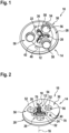
- Fig. 1 and 2 show a patella trial implant 10 comprising a fixation member 12 and a patella component 14.
- the fixation member 12 has a longitudinal axis 16 extending between an anterior portion 18 and a posterior portion 20 of the fixation member 12.
- the posterior portion 20 comprises a tool receiving surface 22 and a radial shoulder 24.
- the anterior portion 18 comprises a thread 26 which can be screwed into a resected patella (see Fig. 3 ).
- the patella component 14 has a posterior articular surface 28 configured to articulate with a femoral surface and an anterior contact surface 30 configured to contact a newly cut surface 32 of a resected patella 34.
- the patella component 14 has a guide slot 36 defining at least one guide axis 38a, 38b, 38c extending in parallel to the anterior contact surface 30 (see Fig. 4 ).
- the fixation member 12 engages in the guide slot 36, and the patella component 14 and the fixation member 12 are movable relative to each other in translation along the at least one guide axis 38a, 38b, 38c and in rotation about the longitudinal axis 16 of the fixation member 12.
- the guide slot 36 comprises a web portion 40 (see Fig. 2 ) extending along the guide slot 36 and supporting the radial shoulder 24 of the fixation member 12.
- the guide slot 36 further comprises an additional web portion 42 (see Fig. 1 ) spaced apart from and extending in parallel to the web portion 40.
- the web portion 40 and the additional web portion 42 secure the posterior portion 20 of the fixation member 12 to the patella component 14.
- the additional web portion 42 delimits a tool slot 44 for access of a fixation tool 46 to the tool receiving surface 22 of the fixation member 12 (see Figures 4 and 5 ).
- the width of the tool slot 44 is smaller than a width of the guide slot 36.
- the additional web portion 42 is formed in one piece with a posterior material section 48 of the patella component 14 which includes the posterior articular surface 28 (see Fig. 1 ).
- the web portion 40 is provided as a separate part (see Fig. 2 ) which is connected to the patella component 14, in particular by laser welding.
- the patella component 14 has a plurality of drilling holes 50 each extending along a drilling hole axis 52 and between a cylindrical posterior receiving portion 54 and a ring-shaped anterior abutment portion 56, see Figures 1 and 2 .
- the anterior abutment portions 56 have respective abutment surfaces 58, wherein the abutment surfaces 58 are at equidistance to the anterior contact surface 30.
- the receiving portion 54 has a greater cross section than the abutment portion 56 such that a drilling guide portion 62 of a drilling guide tool 60 (see Figures 7 and 8 ) is insertable from the posterior articular surface 28 of the patella component 14 into the receiving portion 54 and abutting against the abutment portion 56.
- the newly cut surface 32 of the resected patella 34 extends in parallel to a proximal-distal axis 64, corresponding to an extension direction of a patellar tendon 66, and in parallel to a medio-lateral axis 68.
- the patella component 14 further comprises protrusions 70 (see Figures 2 and 3 ) which protrude from the anterior contact surface 30 and which are to be engaged with the patella 34.
- the trial implant 10 is positioned such that the anterior portion 18 of the fixation member 12 contacts the newly cut surface 32 of the patella 34.
- the fixation member 12 is threaded into the patella 34 such that the newly cut surface 32 of the patella 34 and the anterior contact surface 30 of the patella component 14 are still distant from one another (in particular such that the protrusions 70 do not yet touch the newly cut surface 32), see Fig. 3 .
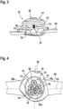
- the patella component 14 can be positioned in relation to the patella 34, in particular in a transitional manner along the guide axes 38a, 38b, 38c as indicated by transitional arrows 72, and in a rotational manner, as indicated by rotational arrows 74 in Fig. 4 .
- the patella component 14 is secured to the patella 34 by means of screwing the anterior portion 18 of fixation member 12 into the patella 34 by means of the fixation tool 46, see Figures 5 and 6 .
- This step involves the protrusions 70 penetrating the newly cut surface 32 and providing a protection against twisting of the patella component 14 in relation to the patella 34.
- This system comprises a drilling guide tool 60 having drilling guide portions 62 which are provided by drilling sleeves 72 which are attached to a support element 74.
- the drilling guide tool 60 comprises two arms 76 and 78, wherein a first arm 76 comprises the support element 18 and the drilling guide portions 62 to be arranged on the posterior of the patella 34 and wherein a second arm 78 comprises a counterholder 80 to to be arranged on the anterior of the patella 34.
- the support element 74 and the sleeves 72 provide drilling tool passages 82 (see Figures 7 and 10 ) for a drilling tool 84 (see Figures 12 and 13 ).
- the support element 74 further comprises a fixation tool passage 84 (see Figures 8 and 10 ) for the fixation tool 46 (see Fig. 11 ).
- the drilling guide portions are limited by respective end surfaces 86 facing away from the support element 74 and preferably extending in the same plane 88, see Fig. 10 .
- the drilling guide portions 62 of drilling guide tool 60 are inserted into the receiving portions 54 of the drilling holes 50 of the patella component 14 until the end surfaces 86 abut to the abutment surfaces 58 of the abutment portions 56, see Figures 7 to 10 .
- the patella trial implant 10 may be repositioned with respect to the patella 34 while the drilling guide portions 62 of the drilling guide tool 60 are received within the receiving portions 54 of the patella component 14, see Fig. 11 .
- This repositioning includes the use of the fixation tool 46 which is inserted into the fixation tool passage 84 of the support element 74, into the tool slot 44 and into the tool receiving surface 22 of the fixation member 12.
- the fixation member 12 may be unscrewed to an extent which allows for repositioning of the patella component 14 in a manner as described above with respect to Fig. 4 but with the drilling guide tool 60 being already engaged with the patella component 14.
- the final drilling step involves the insertion of the drilling tool 84 into one of the drilling holes passage 82 of the drilling guide tool 60, through an abutment portion 56 and into the patella 34, see Figures 10 , 12 and 13 .
Landscapes
- Health & Medical Sciences (AREA)
- Orthopedic Medicine & Surgery (AREA)
- Life Sciences & Earth Sciences (AREA)
- Veterinary Medicine (AREA)
- Animal Behavior & Ethology (AREA)
- Surgery (AREA)
- Oral & Maxillofacial Surgery (AREA)
- Engineering & Computer Science (AREA)
- Biomedical Technology (AREA)
- Heart & Thoracic Surgery (AREA)
- Public Health (AREA)
- General Health & Medical Sciences (AREA)
- Transplantation (AREA)
- Nuclear Medicine, Radiotherapy & Molecular Imaging (AREA)
- Molecular Biology (AREA)
- Medical Informatics (AREA)
- Dentistry (AREA)
- Physical Education & Sports Medicine (AREA)
- Cardiology (AREA)
- Vascular Medicine (AREA)
- Surgical Instruments (AREA)
Abstract
Description
- The invention relates to a patella trial implant comprising a fixation member having a longitudinal axis extending between an anterior portion and a posterior portion; a patella component having a posterior articular surface configured to articulate with a femoral surface and having an anterior contact surface configured to contact a resected patella; wherein the patella component has a guide slot defining at least one guide axis extending in parallel to the anterior contact surface, wherein the the fixation member engages in the guide slot, and wherein the patella component and the fixation member are movable relative to each other in translation along the at least one guide axis and in rotation about the longitudinal axis of the fixation member; wherein the patella component comprises at least one drilling hole.
- Such a patella trial implant is disclosed in
EP 4 197 497 A1 and allows for simple and precise repositioning of the patella trial implant on a newly cut surface of a resected patella. - One object of the present invention is to provide a patella trial implant which allows for simple and precise repositioning of the patella trial implant and which facilitates the step of drilling peg holes into the resected patella.
- This object is solved by the patella impaction device with the features of claim 1. This object is also solved by a system according to claim 11. Preferred embodiments are defined in the dependent claims.
- According to the invention, the at least one drilling hole extends along a drilling hole axis and between a posterior receiving portion and an anterior abutment portion, wherein the receiving portion has a greater cross section than the abutment portion such that a drilling guide portion of a drilling guide tool is insertable from the posterior articular surface into the receiving portion and abutting against the abutment portion.
- The abutment portion provides a stop at which an end surface of a drilling guide portion may rest during the step of drilling a peg hole. One advantage of this is that a contact of the drilling guide portion with a newly cut surface of a resected patella is avoided and that the axial position of the drilling guide portion can be defined more accurately. At the same time, the drilling guide portion is guided and accommodated within the receiving portion of the drilling hole. One advantage of this is that - at least along the receiving portion - a direct contact of a drilling tool and the patella component is avoided.
- In a preferred embodiment, the receiving portion is cylindrical for simple and precise accommodation of a drilling guide portion having a circular external cross section.
- In a further preferred embodiment, the abutment portion is ring-shaped for simple and precise abutment of an end surface of a sleeve-shaped drilling guide portion.
- In a preferred embodiment, the patella component comprises at least two drilling holes (in particular three drilling holes) extending along respective drilling hole axes and between respective posterior receiving portions and anterior abutment portions. This facilitates the preparation of a multitude of peg holes.
- In particular, at least two anterior abutment portions of at least two drilling holes have respective abutment surfaces, wherein these abutment surfaces are at equidistance to the anterior contact surface. In other words: the abutment surfaces preferably extend within the same plane which is parallel to the anterior contact surface. In this way, at least two drilling guide portions can be aligned to abut at the same plane, facilitating a subsequent drilling of peg holes.
- In a preferred embodiment, the anterior contact surface comprises at least one protrusion for local engagement with a newly cut surface of a resected patella. Such a protrusion may be designed a spike which penetrates into a newly cut surface of a resected patella and provides a local form-fit connection to more stably connect the patella component to the resected patella.
- In particular, the fixation member is a screw, preferably a bone screw.
- In a preferred embodiment, the patella component is formed in one piece having one main body including the anterior contact surface and the posterior articular surface.
- In a preferred embodiment, the fixation member comprises a tool receiving surface and a radial shoulder, the anterior portion of the fixation member being configured for fixation to a resected patella, wherein the guide slot comprises a web portion extending along the guide slot and supporting the radial shoulder, wherein the guide slot comprises an additional web portion spaced apart from and extending in parallel to the web portion, the additional web portion securing the posterior portion of the fixation member to the patella component and delimiting a tool slot for access of a fixation tool to the tool receiving surface of the fixation member. In other words: the posterior portion of the fixation member is trapped between the web portion and the additional web portion but the fixation member is still movable with respect to the guide slot. However, the tool receiving surface of the fixation member is accessible via the tool slot.
- In particular, the tool slot has a width which is smaller than a width of the guide slot, thus providing a reliable protection against loss of the fixation member independent of its position along the guide slot of the patella component.
- To provide an easy to produce patella component, the additional web portion may be formed in one piece with a posterior material section of the patella component which includes the posterior articular surface, wherein the web portion is provided as a separate part which is connected to the patella component.
- Preferably, the separate part is connected to the patella component by means of welding, in particular by means of laser welding.
- The invention also relates to a system comprising a patella trial implant as described above and further comprising a drilling guide tool having a support element supporting the at least one drilling guide portion, wherein the at least one drilling guide portion has a size which allows for a form-fit engagement of the drilling guide portion with the receiving portion of the at least one drilling hole of the patella trial implant. The form-fit engagement may involve a clearance fit allowing for minimal movement of the drilling guide portion within the receiving portion. The minimal movement may be limited to e.g. 1 mm or less.
- Preferably, the drilling guide portion is provided by a drilling sleeve. Such a drilling sleeve has a ring-shaped cross-section with an exterior surface to be guided within the receiving portion and with an interior surface providing guidance for a drilling tool.
- In particular, the drilling guide portion has a free cross-section providing a drilling tool passage for a drilling tool, wherein the free cross-section is smaller than a free cross-section of the abutment portion of the patella trial implant. This way, a direct contact of a drilling tool and the patella component can be avoided along the entire length of the drilling hole.
- Preferably the support element supports at least two drilling guide portions thus facilitating the drilling of at least two peg holes and without the need of repositioning a single drilling guide portion.
- In particular, the at least two drilling guide portions are limited by respective end surfaces facing away from the support element, wherein the end surfaces extend in the same plane. In this way, at least two drilling guide portions can be aligned to abut at the same plane, facilitating a subsequent drilling of peg holes. Preferably, the end surfaces are ring-shaped.
- In particular, the end surfaces which extend extend in the same plane are equidistant to a drill tool receiving surface of the support element. This way, drilling guide portions having identical guide lengths are provided, thus facilitating the drilling of peg holes having an identical drilling depth.
- In particular, at least two drilling guide portions have a respective size allowing for a simultaneous form-fit engagement of the drilling guide portions with respective receiving portions of respective drilling holes of the patella trial implant. This way, the drilling of at least two peg holes may be conducted in the same position of the drilling guide tool and there is no need for repositioning a single drilling guide portion.
- Further features and advantages are the subject of the following description and of the diagrammatic illustration of embodiments.
- In the drawing:
- Figure 1
- shows a top perspective view of one embodiment of a patella trial implant;
- Figure 2
- shows a rear perspective view of the patella trial implant;
- Figure 3
- shows a lateral view of an assembly of the patella trial implant being connected to but being still movable with respect to a resected patella;
- Figure 4
- shows a top view of the assembly of
Fig. 3 ; - Figure 5
- shows a top perspective view the assembly of
Fig. 4 and of a fixation tool; - Figure 6
- shows a top view of the assembly of
Fig. 4 , patella trial implant being immovably fixed to the resected patella; - Figure 7
- shows a perspective view of a system including a drilling guide tool prior to engagement with a patella component of the patella trial implant;
- Figure 8
- shows a perspective view of the system of
Fig. 7 , the drilling guide tool being engaged with the patella component; - Figure 9
- shows a top view of the system of
Fig. 8 ; - Figure 10
- shows a sectional view of the system of
Fig. 9 along the cutting line X - X (without fixation member); - Figure 11
- shows a perspective view of the system of
Fig. 8 including a fixation tool; - Figure 12
- shows a perspective view of the system of
Fig. 8 including a drilling tool prior to engagement with the drilling guide tool; and - Figure 13
- shows a perspective view of the system of
Fig. 12 , the drilling tool being engaged with the drilling guide tool and with the patella component and with the resected patella. -
Fig. 1 and 2 show apatella trial implant 10 comprising afixation member 12 and apatella component 14. - The
fixation member 12 has alongitudinal axis 16 extending between ananterior portion 18 and aposterior portion 20 of thefixation member 12. Theposterior portion 20 comprises atool receiving surface 22 and aradial shoulder 24. Theanterior portion 18 comprises athread 26 which can be screwed into a resected patella (seeFig. 3 ). - The
patella component 14 has a posteriorarticular surface 28 configured to articulate with a femoral surface and ananterior contact surface 30 configured to contact a newly cutsurface 32 of a resectedpatella 34. - The
patella component 14 has aguide slot 36 defining at least oneguide axis Fig. 4 ). Thefixation member 12 engages in theguide slot 36, and thepatella component 14 and thefixation member 12 are movable relative to each other in translation along the at least oneguide axis longitudinal axis 16 of thefixation member 12. - The
guide slot 36 comprises a web portion 40 (seeFig. 2 ) extending along theguide slot 36 and supporting theradial shoulder 24 of thefixation member 12. Theguide slot 36 further comprises an additional web portion 42 (seeFig. 1 ) spaced apart from and extending in parallel to theweb portion 40. - The
web portion 40 and theadditional web portion 42 secure theposterior portion 20 of thefixation member 12 to thepatella component 14. Theadditional web portion 42 delimits atool slot 44 for access of afixation tool 46 to thetool receiving surface 22 of the fixation member 12 (seeFigures 4 and5 ). The width of thetool slot 44 is smaller than a width of theguide slot 36. - The
additional web portion 42 is formed in one piece with aposterior material section 48 of thepatella component 14 which includes the posterior articular surface 28 (seeFig. 1 ). Theweb portion 40 is provided as a separate part (seeFig. 2 ) which is connected to thepatella component 14, in particular by laser welding. - The
patella component 14 has a plurality of drilling holes 50 each extending along adrilling hole axis 52 and between a cylindricalposterior receiving portion 54 and a ring-shapedanterior abutment portion 56, seeFigures 1 and 2 . Theanterior abutment portions 56 have respective abutment surfaces 58, wherein the abutment surfaces 58 are at equidistance to theanterior contact surface 30. - The receiving
portion 54 has a greater cross section than theabutment portion 56 such that adrilling guide portion 62 of a drilling guide tool 60 (seeFigures 7 and 8 ) is insertable from the posteriorarticular surface 28 of thepatella component 14 into the receivingportion 54 and abutting against theabutment portion 56. - The newly cut
surface 32 of the resectedpatella 34 extends in parallel to a proximal-distal axis 64, corresponding to an extension direction of apatellar tendon 66, and in parallel to a medio-lateral axis 68. - The
patella component 14 further comprises protrusions 70 (seeFigures 2 and3 ) which protrude from theanterior contact surface 30 and which are to be engaged with thepatella 34. - To position and secure the
patella component 14 to thepatella 34, thetrial implant 10 is positioned such that theanterior portion 18 of thefixation member 12 contacts the newly cutsurface 32 of thepatella 34. Using afixation tool 46, thefixation member 12 is threaded into thepatella 34 such that the newly cutsurface 32 of thepatella 34 and theanterior contact surface 30 of thepatella component 14 are still distant from one another (in particular such that theprotrusions 70 do not yet touch the newly cut surface 32), seeFig. 3 . - In a next step, the
patella component 14 can be positioned in relation to thepatella 34, in particular in a transitional manner along the guide axes 38a, 38b, 38c as indicated bytransitional arrows 72, and in a rotational manner, as indicated byrotational arrows 74 inFig. 4 . - In a next step, the
patella component 14 is secured to thepatella 34 by means of screwing theanterior portion 18 offixation member 12 into thepatella 34 by means of thefixation tool 46, seeFigures 5 and 6 . This step involves theprotrusions 70 penetrating the newly cutsurface 32 and providing a protection against twisting of thepatella component 14 in relation to thepatella 34. - In order to prepare the drilling of peg holes into the
patella 34, a system is provided which is shown in Figures 7 to 15. This system comprises adrilling guide tool 60 having drilling guideportions 62 which are provided by drillingsleeves 72 which are attached to asupport element 74. - The
drilling guide tool 60 comprises twoarms first arm 76 comprises thesupport element 18 and thedrilling guide portions 62 to be arranged on the posterior of thepatella 34 and wherein asecond arm 78 comprises acounterholder 80 to to be arranged on the anterior of thepatella 34. - The
support element 74 and thesleeves 72 provide drilling tool passages 82 (seeFigures 7 and10 ) for a drilling tool 84 (seeFigures 12 and13 ). Thesupport element 74 further comprises a fixation tool passage 84 (seeFigures 8 and10 ) for the fixation tool 46 (seeFig. 11 ). - The drilling guide portions are limited by respective end surfaces 86 facing away from the
support element 74 and preferably extending in thesame plane 88, seeFig. 10 . - In a first drilling preparation step, the
drilling guide portions 62 ofdrilling guide tool 60 are inserted into the receivingportions 54 of the drilling holes 50 of thepatella component 14 until the end surfaces 86 abut to the abutment surfaces 58 of theabutment portions 56, seeFigures 7 to 10 . - Prior to the following drilling step, the
patella trial implant 10 may be repositioned with respect to thepatella 34 while thedrilling guide portions 62 of thedrilling guide tool 60 are received within the receivingportions 54 of thepatella component 14, seeFig. 11 . This repositioning includes the use of thefixation tool 46 which is inserted into thefixation tool passage 84 of thesupport element 74, into thetool slot 44 and into thetool receiving surface 22 of thefixation member 12. Thefixation member 12 may be unscrewed to an extent which allows for repositioning of thepatella component 14 in a manner as described above with respect toFig. 4 but with thedrilling guide tool 60 being already engaged with thepatella component 14. - The final drilling step involves the insertion of the
drilling tool 84 into one of thedrilling holes passage 82 of thedrilling guide tool 60, through anabutment portion 56 and into thepatella 34, seeFigures 10 ,12 and13 .
Claims (16)
- A patella trial implant (10) comprising:a fixation member (12) having a longitudinal axis (16) extending between an anterior portion (18) and a posterior portion (20);a patella component (14) having a posterior articular surface (28) configured to articulate with a femoral surface and having an anterior contact surface (30) configured to contact a resected patella (34);wherein the patella component (14) has a guide slot (36) defining at least one guide axis (38a, 38b, 38c) extending in parallel to the anterior contact surface (30), wherein the fixation member (12) engages in the guide slot (36), and wherein the patella component (14) and the fixation member (12) are movable relative to each other in translation along the at least one guide axis (38a, 38b, 38c) and in rotation about the longitudinal axis (16) of the fixation member (12);wherein the patella component (14) comprises at least one drilling hole (50),characterized in that the at least one drilling hole (50) extends along a drilling hole axis (52) and between a posterior receiving portion (54) and an anterior abutment portion (56), wherein the receiving portion (54) has a greater cross section than the abutment portion (56) such that a drilling guide portion (62) of a drilling guide tool (60) is insertable from the posterior articular surface (28) into the receiving portion (54) and abutting against the abutment portion (56).
- The patella trial implant (10) according to claim 1, characterized in that the receiving portion (54) is cylindrical and/or in that the abutment portion (56) is ring-shaped.
- The patella trial implant (10) according to one of the preceding claims, characterized in that the patella component (14) comprises at least two drilling holes (50) extending along respective drilling hole axes (52) and between respective posterior receiving portions (54) and anterior abutment portions (56).
- The patella trial implant (10) according to claim 3, characterized in that the anterior abutment portions (56) have respective abutment surfaces (58), wherein the abutment surfaces are at equidistance to the anterior contact surface (30).
- The patella trial implant (10) according to one of the preceding claims, characterized in that the anterior contact surface (30) comprises at least one protrusion (70) for local engagement with a newly cut surface (32) of a resected patella (34).
- The patella trial implant (10) according to one of the preceding claims, characterized in that the patella component (14) is formed in one piece having one main body including the anterior contact surface (30) and the posterior articular surface (32).
- The patella trial implant (10) according to one of the preceding claims, characterized in that the fixation member (12) comprises a tool receiving surface (22) and a radial shoulder (24), the anterior portion (18) of the fixation member (12) being configured for fixation to a resected patella (34), wherein the guide slot (36) comprises a web portion (40) extending along the guide slot (36) and supporting the radial shoulder (24), wherein the guide slot (36) comprises an additional web portion (42) spaced apart from and extending in parallel to the web portion (40), the additional web (42) portion securing the posterior (20) portion of the fixation member (12) to the patella component (14) and delimiting a tool slot (44) for access of a fixation tool (46) to the tool receiving surface (22) of the fixation member (12).
- The patella trial implant (10) according to claim 7, characterized in that the tool slot (44) has a width which is smaller than a width of the guide slot (36).
- The patella trial implant (10) according to claim 7 or 8, characterized in that in that the additional web portion (42) is formed in one piece with a posterior material section (48) of the patella component (14) which includes the posterior articular surface (28) and in that the web portion (40) is provided as a separate part which is connected to the patella component (14).
- The patella trial implant (10) according to claim 9, characterized in that the separate part is connected to the patella component (14) by means of welding, in particular by means of laser welding.
- A system comprising a patella trial implant (10) according to one of the preceding claims and a drilling guide tool (60) having a support element (74) supporting the at least one drilling guide portion (62), wherein the at least one drilling guide portion (62) has a size which allows for a form-fit engagement of the drilling guide portion (62) with the receiving portion (54) of the at least one drilling hole (50) of the patella trial implant (10).
- The system according to claim 11, characterized in that the drilling guide portion (62) is provided by a drilling sleeve (72).
- The system according to claim 11 or 12, characterized in that the drilling guide portion (62) has a free cross-section providing a drilling tool passage (82) for a drilling tool (84), wherein the free cross-section is smaller than a free cross-section of the abutment portion (56) of the patella trial implant (10) .
- The system according to one of the claims 11 to 13, characterized in that in that the support element (74) supports at least two drilling guide portions (62).
- The system according to claim 14, characterized in that the at least two drilling guide portions (62) are limited by respective end surfaces (86) facing away from the support element (74), the end surfaces (86) extending in the same plane.
- The system according to claim 14 or 15, characterized in that the at least two drilling guide portions (62) have a respective size allowing for a simultaneous form-fit engagement of the drilling guide portions (62) with respective receiving portions (54) of respective drilling holes (50) of the patella trial implant (10).
Priority Applications (1)
| Application Number | Priority Date | Filing Date | Title |
|---|---|---|---|
| EP23212949.4A EP4563123A1 (en) | 2023-11-29 | 2023-11-29 | Patella trial implant and system comprising a patella trial implant and a drilling guide tool |
Applications Claiming Priority (1)
| Application Number | Priority Date | Filing Date | Title |
|---|---|---|---|
| EP23212949.4A EP4563123A1 (en) | 2023-11-29 | 2023-11-29 | Patella trial implant and system comprising a patella trial implant and a drilling guide tool |
Publications (1)
| Publication Number | Publication Date |
|---|---|
| EP4563123A1 true EP4563123A1 (en) | 2025-06-04 |
Family
ID=89029487
Family Applications (1)
| Application Number | Title | Priority Date | Filing Date |
|---|---|---|---|
| EP23212949.4A Pending EP4563123A1 (en) | 2023-11-29 | 2023-11-29 | Patella trial implant and system comprising a patella trial implant and a drilling guide tool |
Country Status (1)
| Country | Link |
|---|---|
| EP (1) | EP4563123A1 (en) |
Citations (4)
| Publication number | Priority date | Publication date | Assignee | Title |
|---|---|---|---|---|
| US20130023890A1 (en) * | 2011-06-30 | 2013-01-24 | Maja Kecman | Patella clamp and drill guide surgical instrument |
| US20130079787A1 (en) * | 2011-09-28 | 2013-03-28 | Richard Spencer Jones | Rotatable patella drill guide |
| US20140094818A1 (en) * | 2012-09-28 | 2014-04-03 | Matthew S. Wallace | Patella drill guide and trial surgical instrument having an alignment bore formed therein and method of using the same |
| EP4197497A1 (en) | 2021-12-15 | 2023-06-21 | Aesculap AG | Patella trial implant |
-
2023
- 2023-11-29 EP EP23212949.4A patent/EP4563123A1/en active Pending
Patent Citations (4)
| Publication number | Priority date | Publication date | Assignee | Title |
|---|---|---|---|---|
| US20130023890A1 (en) * | 2011-06-30 | 2013-01-24 | Maja Kecman | Patella clamp and drill guide surgical instrument |
| US20130079787A1 (en) * | 2011-09-28 | 2013-03-28 | Richard Spencer Jones | Rotatable patella drill guide |
| US20140094818A1 (en) * | 2012-09-28 | 2014-04-03 | Matthew S. Wallace | Patella drill guide and trial surgical instrument having an alignment bore formed therein and method of using the same |
| EP4197497A1 (en) | 2021-12-15 | 2023-06-21 | Aesculap AG | Patella trial implant |
Similar Documents
| Publication | Publication Date | Title |
|---|---|---|
| US6228086B1 (en) | Modular intramedullary nail | |
| KR0185746B1 (en) | Fracture Fixation between Intermedullary Bone | |
| EP2072016B1 (en) | Bone plate instrument and method | |
| JP2007268294A (en) | Modular intramedullary nail | |
| JP3650623B2 (en) | Intramedullary nail | |
| EP3060146B1 (en) | A device for bone support with improved rotational stability | |
| KR101004561B1 (en) | Bone marrow pin | |
| AU2008204818C1 (en) | Percutaneous intramedullary bone repair device | |
| EP2441398B1 (en) | Bone plate aiming block | |
| EP1624820B1 (en) | An intramedullary nail assembly | |
| KR101269381B1 (en) | Longitudinal Implants for Endodontics | |
| US20100057088A1 (en) | Distal Femoral Cutting Guide | |
| KR20040055583A (en) | Tubular element for an implant to be used in spine or bone surgery and implant having such an element | |
| WO2010122112A1 (en) | Surgical instrumentation for fitting an osteosynthesis nail | |
| US20130338675A1 (en) | Glenoid baseplate insertion tool | |
| EP3210550B1 (en) | Instrument guide assembly for a bone plate and kit of a bone plate with such an instrument guide assembly | |
| AU2019428406B2 (en) | Distal radius fracture fixation device | |
| EP1974681B1 (en) | Implant set | |
| EP4461238A1 (en) | Medical device with sleeve clamping mechanism | |
| JP7360576B1 (en) | Fixation device for fracture treatment | |
| CA2191427C (en) | Intramedullary nail |
Legal Events
| Date | Code | Title | Description |
|---|---|---|---|
| PUAI | Public reference made under article 153(3) epc to a published international application that has entered the european phase |
Free format text: ORIGINAL CODE: 0009012 |
|
| STAA | Information on the status of an ep patent application or granted ep patent |
Free format text: STATUS: THE APPLICATION HAS BEEN PUBLISHED |
|
| AK | Designated contracting states |
Kind code of ref document: A1 Designated state(s): AL AT BE BG CH CY CZ DE DK EE ES FI FR GB GR HR HU IE IS IT LI LT LU LV MC ME MK MT NL NO PL PT RO RS SE SI SK SM TR |
|
| STAA | Information on the status of an ep patent application or granted ep patent |
Free format text: STATUS: REQUEST FOR EXAMINATION WAS MADE |
|
| 17P | Request for examination filed |
Effective date: 20250711 |
|
| GRAP | Despatch of communication of intention to grant a patent |
Free format text: ORIGINAL CODE: EPIDOSNIGR1 |
|
| STAA | Information on the status of an ep patent application or granted ep patent |
Free format text: STATUS: GRANT OF PATENT IS INTENDED |
|
| RIC1 | Information provided on ipc code assigned before grant |
Ipc: A61F 2/38 20060101AFI20260309BHEP Ipc: A61B 17/16 20060101ALI20260309BHEP Ipc: A61B 17/17 20060101ALI20260309BHEP Ipc: A61F 2/46 20060101ALI20260309BHEP Ipc: A61F 2/30 20060101ALN20260309BHEP |
|
| INTG | Intention to grant announced |
Effective date: 20260331 |