EP4562991A1 - Agricultural implements and related methods and systems - Google Patents
Agricultural implements and related methods and systems Download PDFInfo
- Publication number
- EP4562991A1 EP4562991A1 EP24208254.3A EP24208254A EP4562991A1 EP 4562991 A1 EP4562991 A1 EP 4562991A1 EP 24208254 A EP24208254 A EP 24208254A EP 4562991 A1 EP4562991 A1 EP 4562991A1
- Authority
- EP
- European Patent Office
- Prior art keywords
- frame section
- actuator
- wing
- intermediate frame
- center
- Prior art date
- Legal status (The legal status is an assumption and is not a legal conclusion. Google has not performed a legal analysis and makes no representation as to the accuracy of the status listed.)
- Pending
Links
Images




Classifications
-
- A—HUMAN NECESSITIES
- A01—AGRICULTURE; FORESTRY; ANIMAL HUSBANDRY; HUNTING; TRAPPING; FISHING
- A01B—SOIL WORKING IN AGRICULTURE OR FORESTRY; PARTS, DETAILS, OR ACCESSORIES OF AGRICULTURAL MACHINES OR IMPLEMENTS, IN GENERAL
- A01B63/00—Lifting or adjusting devices or arrangements for agricultural machines or implements
- A01B63/14—Lifting or adjusting devices or arrangements for agricultural machines or implements for implements drawn by animals or tractors
- A01B63/24—Tools or tool-holders adjustable relatively to the frame
- A01B63/32—Tools or tool-holders adjustable relatively to the frame operated by hydraulic or pneumatic means without automatic control
-
- A—HUMAN NECESSITIES
- A01—AGRICULTURE; FORESTRY; ANIMAL HUSBANDRY; HUNTING; TRAPPING; FISHING
- A01B—SOIL WORKING IN AGRICULTURE OR FORESTRY; PARTS, DETAILS, OR ACCESSORIES OF AGRICULTURAL MACHINES OR IMPLEMENTS, IN GENERAL
- A01B73/00—Means or arrangements to facilitate transportation of agricultural machines or implements, e.g. folding frames to reduce overall width
- A01B73/02—Folding frames
- A01B73/04—Folding frames foldable about a horizontal axis
- A01B73/044—Folding frames foldable about a horizontal axis the axis being oriented in a longitudinal direction
-
- A—HUMAN NECESSITIES
- A01—AGRICULTURE; FORESTRY; ANIMAL HUSBANDRY; HUNTING; TRAPPING; FISHING
- A01B—SOIL WORKING IN AGRICULTURE OR FORESTRY; PARTS, DETAILS, OR ACCESSORIES OF AGRICULTURAL MACHINES OR IMPLEMENTS, IN GENERAL
- A01B79/00—Methods for working soil
Definitions
- Embodiments of the present disclosure relate generally to machines and methods for working agricultural fields. More particularly, embodiments relate to agricultural implements (e.g., planters, tillage implements, etc.) and to methods of controlling such agricultural implements.
- agricultural implements e.g., planters, tillage implements, etc.
- Planting an agricultural field may be performed with a planter including an agricultural implement having planter row units configured to deposit seeds in trenches formed by discs or other mechanisms.
- the agricultural implement may be towed behind a primary vehicle, such as a tractor.
- the agricultural implement may include a frame section operably coupled to the tractor with a tow hitch.
- Row units are typically spaced along a toolbar of a planter, which may include multiple sections.
- a 3-section planter has a center section, a left wing section, and a right wing section, each having several ground-engaging row units.
- a 3-section planter may have a nominal working width from about 30 feet (9.1 m) to about 40 feet (12.2 m), but can be wider or narrower.
- the left and right wing sections may each rotate upward from the center section, as depicted in U.S. Patent 11,229,152, "Ground-engaging Implement with Lateral Position Adjustment," granted January 25, 2022 .
- the left and right wing sections may fold to be above the center section, as shown in U.S. Patent 8,807,236, "Agricultural Implement Incorporating Stack-fold Planter," granted August 19, 2014 .
- neighboring row units may be spaced from one another by at least a minimum distance to prevent the row units operably coupled to the wing sections from inadvertently contacting the row units operably coupled to the center section or from contacting the frame.
- Linkages and/or rephasing cylinders connect the sections of the planter together so that they fold or extend at the same time and at the same rate and facilitate synchronous folding of the wing sections to prevent the row units from inadvertently contacting one another and/or the frame.
- an agricultural implement comprises a center frame section, an intermediate frame section pivotally coupled to a side of the center frame section, a wing frame section pivotally coupled to the intermediate frame section, a first actuator operably coupled to the center frame section and the intermediate frame section, a second actuator operably coupled to the wing frame section and the intermediate frame section, a first sensor configured to sense a position of the intermediate frame section relative to the center frame section, a second sensor configured to sense a position of the wing frame section relative to the intermediate frame section, and a control system configured to independently control the first actuator and the second actuator to travel by a different percentage of a total displacement based on the sensed positions of the intermediate frame section and the wing frame section.
- the first sensor comprises a rotary sensor configured to determine an angle between the center frame section and the intermediate frame section. In other aspects, the first sensor comprises a linear sensor configured to determine a position of the first actuator.
- control system is configured to cause the second actuator to rotate the wing frame section to be substantially non-parallel to the center frame section.
- the control system may be configured to cause the second actuator to cause an angle between the wing frame section and the intermediate frame section to be different than an angle between the intermediate frame section and the center frame section.
- control system is configured to cause the second actuator to adjust the position of wing frame section relative to the intermediate frame section after causing the first actuator to adjust the position of the intermediate frame section relative to the center frame section.
- the first actuator may comprise a first hydraulic cylinder
- the second actuator may comprise a second hydraulic cylinder.
- each of the first actuator and the second actuator are operably couped to the intermediate frame section at a connector.
- the agricultural implement may further comprise a wing tool bar operably coupled to the wing frame section, and row units operably coupled to the wing frame section.
- the control system may be configured to cause second actuator to change the position of the wing frame section at a different rate than the first actuator changes the position of the intermediate frame section.
- the first actuator is operably coupled to the center frame section and the intermediate frame section.
- a method of operating an agricultural implement comprises causing a first actuator to rotate an intermediate frame section relative to a center frame section, determining, with a first sensor, a position of the intermediate frame section relative to the center frame section, determining, with a second sensor, a position of a wing frame section relative to the intermediate frame section, and causing a second actuator operably coupled to the wing frame section and the intermediate frame section to change an angle between the wing frame section and the intermediate frame section to be different than an angle between the intermediate frame section and the center frame section.
- Determining, with a first sensor, a position of the intermediate frame section relative to the center frame section comprises measuring the angle between the intermediate frame section and the center frame section. In other embodiments, determining, with a first sensor, a position of the intermediate frame section relative to the center frame section comprises measuring a linear displacement of the first actuator.
- Changing an angle between the wing frame section and the intermediate frame section comprises changing the angle between the wing frame section and the intermediate frame section at a different rate than changing the angle between the intermediate frame section and the center frame section.
- changing an angle between the wing frame section and the intermediate frame section comprises causing the second actuator to change the angle between the wing frame section and the intermediate frame section after causing the first actuator to rotate the intermediate frame section relative to the center frame section.
- changing an angle between the wing frame section and the intermediate frame section comprises changing the angle between the wing frame section and the intermediate frame section at the same time as causing the first actuator to rotate the intermediate frame section relative to the center frame section.
- a control system for an agricultural implement comprises at least one processor, and at least one non-transitory computer-readable storage medium storing instructions thereon that, when executed by the at least one processor, cause the control system to cause a first actuator to rotate an intermediate frame section relative to a center frame section by a first amount, receive, from a first sensor, an indication of a position of the intermediate frame section relative to the center frame section, receive, from a second sensor, an indication of a position of a position of the wing frame section relative to the intermediate frame section, and cause a second actuator to rotate the wing frame section relative to the intermediate frame section by a second amount different than the first amount, at a different time than the intermediate frame section is rotated relative to the center frame section, or both.
- the instructions cause the control system to cause the second actuator to rotate the wing frame section relative to the intermediate frame section by the second amount.
- control system is configured to cause the second actuator to rotate the wing frame section relative to the intermediate frame section at a different time than the first actuator causes the intermediate frame section to rotate relative to the center frame section.
- the terms “comprising,” “including,” “containing,” “characterized by,” and grammatical equivalents thereof are inclusive or open-ended terms that do not exclude additional, unrecited elements or method steps, but also include the more restrictive terms “consisting of” and “consisting essentially of” and grammatical equivalents thereof.
- the term "may” with respect to a material, structure, feature, or method act indicates that such is contemplated for use in implementation of an embodiment of the disclosure, and such term is used in preference to the more restrictive term “is” so as to avoid any implication that other, compatible materials, structures, features, and methods usable in combination therewith should or must be excluded.
- the term “configured” refers to a size, shape, material composition, and arrangement of one or more of at least one structure and at least one apparatus facilitating operation of one or more of the structure and the apparatus in a predetermined way.
- spatially relative terms such as “beneath,” “below,” “lower,” “bottom,” “above,” “upper,” “top,” “front,” “rear,” “left,” “right,” and the like, may be used for ease of description to describe one element's or feature's relationship to another element(s) or feature(s) as illustrated in the figures. Unless otherwise specified, the spatially relative terms are intended to encompass different orientations of the materials in addition to the orientation depicted in the figures.
- the term "substantially" in reference to a given parameter, property, or condition means and includes to a degree that one of ordinary skill in the art would understand that the given parameter, property, or condition is met with a degree of variance, such as within acceptable manufacturing tolerances.
- the parameter, property, or condition may be at least 90.0% met, at least 95.0% met, at least 99.0% met, or even at least 99.9% met.
- the term "about” used in reference to a given parameter is inclusive of the stated value and has the meaning dictated by the context (e.g., it includes the degree of error associated with measurement of the given parameter).
- ranges are used as shorthand for describing each and every value that is within the range. Any value within the range can be selected as the terminus of the range.
- the terms “longitudinal” and “transverse” are made in relation to a machine's (e.g., agricultural implement's) normal direction of travel.
- the term “longitudinal” equates to the fore-and-aft direction
- the term “transverse” equates to the crosswise direction, or left and right.
- the terms “axial” and “radial” are made in relation to a rotating body such as a shaft, wherein axial relates to a direction along the rotation axis and radial equates to a direction perpendicular to the rotation axis.
- FIG. 1A is a simplified top view of a tractor 102 pulling (e.g., towing) an agricultural implement 104 (also referred to as an "implement") in a forward direction 106, the forward direction 106 being an intended direction of travel of the agricultural implement 104 while being pulled by the tractor 102.
- the tractor 102 includes wheels 108, an engine, and a chassis 110 supported by the wheels 108 that contact a surface of the ground 112.
- the agricultural implement 104 includes a frame 120 carrying a toolbar 150 and row units 160 connected to the toolbar 150.
- the row units 160 may be attached to the toolbar 150 and carried by the toolbar 150.
- a control system 114 which may include a central processing unit (“CPU”), memory, implement controller, and one or more input/output (I/O) devices 116 (e.g., a graphical user interface ("GUI") (e.g., a touch-screen interface)), is typically located in an operator cabin 118 of the tractor 102.
- the control system 114 may be configured to communicate with the agricultural implement 104, such as by wired or wireless communication.
- Various control components e.g., a first actuator 132, a second actuator 134, a first sensor 136, and a second sensor 138
- the I/O device 116 is configured to receive a user input, such as from an operator of the tractor 102 and/or the agricultural implement 104.
- the user input may be a command to fold the agricultural implement 104 (e.g., such as for transport of the agricultural implement 104) and/or to extend the agricultural implement 104 (such as for a planting operation).
- the I/O device 116 may be configured to receive user input indicative of a predetermined setpoint of the frame 120 and/or toolbar 150.
- Each of the row units 160 may be in operable communication with a central hopper 162 containing seed to be planted and/or fertilizer to be applied. That is, the row units 160 may be planter and/or fertilizer row units.
- the frame 120 of the agricultural implement 104 is connected to the tractor 102 by a tow hitch 164 (only a portion of which is illustrated in the view of FIG. 1A ), which may comprise, for example, a 3-point hitch.
- a height of the toolbar 150 may be controlled by the tow hitch 164, as shown in U.S. Patent Application Publication 2021/0315147, "Systems comprising agricultural implements connected to lifting hitches and related control systems and methods," published October 14, 2021 .
- the agricultural implement 104 may optionally be supported in the field by the row units 160, such as at least center row units 160 connected to a center frame section 122 of the frame 120.
- the row units 160 may each include a trench opening assembly (or "opening wheels") at a front thereof and a trench closing assembly (or “closing wheels”) at a rear thereof. In use and operation, the trench opening assemblies and the trench closing assemblies may contact the ground 112.
- the agricultural implement 104 is supported by one or more wheels operably coupled to the frame 120.
- the row units 160 may be any type of ground-engaging device for planting, seeding, fertilizing, tilling, or otherwise working crops for soil, typically in rows, and may be substantially similar to the row units described in International Patent Publication WO 2021/205245 A1, "Agricultural Implements Having Row Unit Position Sensors and at Least One Adjustable Wheel, and Related Control Systems and Methods," published October 14, 2021 .
- FIG. 1A the frame 120 and the toolbar 150 are in an extended orientation.
- the frame 120 and the toolbar 150 may be in an extended configuration while performing an agricultural operation (e.g., a planting or fertilization operation) with the agricultural implement 104.
- FIG. 1B and FIG. 1C are a respective simplified perspective view and rear view of the agricultural implement 104 in which the frame 120 and the toolbar 150 are in the extended configuration and on level ground;
- FIG. 1D is a simplified rear view of the agricultural implement 104 in which the frame 120 and the toolbar 150 are in the extended configuration and over sloped and terraced ground;
- FIG. 1E and FIG. 1F are a respective simplified perspective view and rear view of the agricultural implement 104 in which the frame 120 and the toolbar 150 are in a folded (or retracted) configuration.
- the frame 120 includes a center frame section 122 to which the tow hitch 164 and the central hopper 162 are operably coupled.
- Each lateral side of the center frame section 122 may be operably coupled to an intermediate frame section 124 at a first joint 126.
- Each intermediate frame section 124 may be operably coupled to a wing frame section 128 at a second joint 130.
- the first joint 126 and the second joint 130 may be configured to facilitate independent lifting of the frame 120 (e.g., of the wing frame section 128 and the intermediate frame section 124) and tilting of the wing frame section 128 with respect to the center frame section 122.
- tilting of the frame 120 or the wing frame section 128 means adjusting a relative angle between the wing frame section 128 and the intermediate frame section 124 and adjusting a corresponding orientation of row units 160 operably coupled to a center toolbar 152 relative to an orientation of row units 160 operably coupled to a wing toolbar 154.
- a 0° tilt may correspond to a relative angle of 0° between the wing frame section 128 and the intermediate frame section 124 (e.g., the wing frame section 128 being substantially parallel to the intermediate frame section 128 and the row units 160 of the center toolbar 152 being substantially co-linear with the row units 160 of the wing toolbar 154).
- the toolbar 150 may include a center toolbar 152 operably coupled to the center frame section 122, and wing toolbars 154 operably coupled to the wing frame sections 128.
- the toolbar 150 is not operably coupled to the intermediate frame section 124 and there are no row units 160 operably coupled to the intermediate frame section 124 (e.g., by means of a toolbar).
- the center toolbar 152 is longer than the center frame section 122 and the wing toolbars 154 are longer than the wing frame sections 128.
- the wing toolbars 154 are separated from (e.g., not directly connected to) the center toolbar 152.
- a position of the center frame section 122 may be substantially fixed with respect to the position of the central hopper 162 and the tow hitch 164. In use and operation, the position of the center frame section 122 may be substantially fixed with respect to the tractor 102.
- the intermediate frame section 124 may be configured to rotate relative to the center frame section 122 about the first joint 126
- the wing frame section 128 may be configured to rotate relative to the intermediate frame section 124 about the second joint 130.
- the first joint 126 may be configured to constrain relative motion between the intermediate frame section 124 and the center frame section 122 about a common axis (e.g., about the first joint 126 in and out of the page in the view of FIG. 1C ); and the second joint 130 may be configured to constrain relative motion between the intermediate frame section 124 and the wing frame section 128 about a common axis (e.g., about the second joint 130 in and out of the page in the view of FIG. 1C ).
- the first joint 126 and the second joint 130 may individually comprise a pin joint (e.g., a roller bearing) or a hinge joint.
- a longitudinal axis Lc of the center frame section 122 may be substantially parallel to a longitudinal axis L W of the wing frame section 128 when the frame 120 is in the extended configuration and on level ground 112 and when the frame 120 is in the folded configuration.
- the wing frame section 128 e.g., the longitudinal axis L w of the wing frame section 128) may be substantially parallel to the center frame section 122 (e.g., to the longitudinal axis Lc of the center frame section 122) and to the ground 112.
- the wing frame section 128 may be oriented at an angle with respect to the center frame section 122.
- the intermediate frame section 124 may be oriented at an angle ⁇ 1 relative to the center frame section 122; and the wing frame section 128 may be oriented at an angle ⁇ 2 relative to the intermediate frame section 124.
- the angle ⁇ 1 between the intermediate frame section 124 and the center frame section 122 may be other than parallel, such as between about 150° and about 170° (or between about 10° and about 30°).
- the angle ⁇ 2 between the wing frame section 128 and the intermediate frame section 124 may be substantially the same as the angle ⁇ 1.
- angles ⁇ 1 and ⁇ 2 may be different when the wing frame section 128 is in an extended configuration, such as when the wing frame section 128 is over ground 112 that is not on the same plane (e.g., level with) the ground over which the center frame section 122 travels.
- Rotation of the intermediate frame section 124 with respect to the center frame section 122 about the first joint 126 may cause the frame 120 (e.g., the wing frame section 128 and the intermediate frame section 124) to lift and/or lower (depending on the direction of rotation) with respect to the center frame section 122 and the ground 112.
- the frame 120 e.g., the wing frame section 128 and the intermediate frame section 12
- rotation of the intermediate frame section 124 relative to the center frame section 122 may lift or lower the wing frame section 128 and the intermediate frame section 124.
- the wing frame section 128 may be lifted (e.g., raised) to place the frame 120 and the toolbar 150 in the folded configuration and to lift the coupled row units 160 from the ground 112.
- the wing frame section 128 and the intermediate frame section 124 may be lifted and/or lowered without tilting the wing frame section 128 relative to the intermediate frame section 124.
- Rotation of the first joint 126 may lift and lower the wing frame section 128 and cause the orientation of the wing frame section 128 relative to the ground 112 and the center frame section 122 to change while the longitudinal axis L w of the wing frame section 128 remains in the same orientation with respect to the longitudinal axis L I of the intermediate frame section 124 (as long as the wing frame section 128 is not concurrently rotated about the second joint 130).
- the frame 120 may be lifted and/or lowered with a first actuator 132.
- the first actuator 132 is fixedly coupled to each of the intermediate frame section 124 and the center frame section 122.
- the first actuator 132 may be operably coupled to the center frame section 122 at a first connector 123 and to the intermediate frame section 124 at a second connector 125.
- the first connector 123 may be fixedly coupled (e.g., attached) to the center frame section 122 and the second connector 125 may be fixedly coupled to (e.g., attached to or comprise a portion of) the intermediate frame section 124.
- the second connector 125 is integral with the intermediate frame section 124.
- the first actuator 132 when the frame 120 is in an extended configuration, the first actuator 132 may be in an extended configuration, and when the frame 120 is in a folded configuration, the first actuator 132 may be in a retracted configuration.
- the first actuator 132 may include, for example, a hydraulic cylinder, an electric motor, a pneumatic actuator, or another type of actuator.
- the first actuator 132 comprises a hydraulic cylinder.
- the first actuator 132 may be configured to rotate the intermediate frame section 124 relative to the center frame section 122 about the first joint 126 to lift the frame 120 (e.g., the intermediate frame section 124 and the wing frame section 128).
- the first actuator 132 may be configured to cause the angle ⁇ 1 between the intermediate frame section 124 (e.g., the longitudinal axis L I of the intermediate frame section 124) and the center frame section 122 (e.g., the longitudinal axis Lc of the center frame section 122) to change.
- extension of the first actuator 132 e.g., extending the piston out of the cylinder tube
- the angle ⁇ 1 may increase and retraction of the first actuator 132 may cause the angle ⁇ 1 to decrease.
- the first actuator 132 may be configured to cause the angle ⁇ 1 between the center frame section 122 and the intermediate frame section 124 to change by up to at least about 60°, such as up to about least about 75°, up to about 90°, or even up to about 100° between the extended configuration and the retracted configuration.
- the disclosure is not so limited, and the amount that the first actuator 132 may cause the angle ⁇ 1 to change may be different than that described.
- rotation of the wing frame section 128 relative to the intermediate frame section 124 about the second joint 130 may change the angle ⁇ z to tilt the wing frame section 128 with respect to the intermediate frame section 124.
- rotation of the wing frame section 128 relative to the intermediate frame section 124 may also change an angle between the wing frame section 128 and the center frame section 122.
- the wing frame section 128 may be tilted up or down based on the direction of rotation of the second joint 130.
- the tilt of the wing frame section 128 may be independently adjusted relative to the lift of the frame 120 to contact unlevel ground with row units 160 operably coupled to the wing toolbar 154.
- the wing frame section 128 may be tilted with a second actuator 134.
- the second actuator 134 may be operably coupled to the wing frame section 128 at a third connector 129 and to the intermediate frame section 124 at the second connector 125.
- the second actuator 134 is fixedly coupled to each of the intermediate frame section 124 and the wing frame section 128.
- the third connector 129 may be fixedly coupled (e.g., attached) to the wing frame section 128.
- the second actuator 134 when the frame 120 is in an extended configuration, the second actuator 134 may be in a retracted configuration, and when the frame 120 is in a folded configuration, the second actuator 132 may be in an extended configuration.
- the second actuator 134 may be configured to cause the angle ⁇ 2 to change by up to at least about 45°, such as up to at least about 60°.
- the disclosure is not so limited, and the amount that the second actuator 134 may cause the angle ⁇ 2 to change may be different than that described.
- the wing frame section 128 may be configured to be tilted downwards, such as when the wing frame section 128 is located over ground 112 that is relatively lower than the ground 112 over which the center frame section 122 is disposed; and the wing frame section 128 may be configured to be tilted upwards, such as when the wing frame section 128 is located over ground 112 that is relatively higher than the ground 112 over which the center frame section 122 is disposed.
- the second actuator 134 may be extended to cause the wing frame section 128 to rotate downwards relative to the center frame section 122 and the second actuator 134 may be retracted to cause the wing frame section 128 to rotate upwards relative to the center frame section 122.
- the second actuator 134 may be extended to cause the wing frame section 128 to rotate downwards relative to the center frame section 122 and the second actuator 134 may be retracted to cause the wing frame section 128 to rotate upwards relative to the center frame section 122.
- the longitudinal axis L W of the wing frame section 128 may not be parallel to the longitudinal axis Lc of the center frame section 122 when the frame 120 is in the extended configuration.
- the wing frame section 128 may be tilted downwards relative to the intermediate frame section 124 such that the row units 160 operably coupled to the wing toolbar 154 contact ground 112 that is lower than the ground 112 over the center frame section 122 and the center toolbar 152.
- the wing frame section 128 may be tilted upwards relative to the intermediate frame section 124 such that the row units 160 operably coupled to the wing toolbar 154 contact ground 112 that is higher than the ground 112 over the center frame section 122 and the center toolbar 152.
- the wing frame section 128 may be tilted upwards relative to the intermediate frame section 124 such that the row units 160 operably coupled to the wing toolbar 154 contact ground 112 that is higher than the ground 112 over the center frame section 122 and the center toolbar 152.
- the wing frame section 128 may be tilted downwards relative to the intermediate frame section 124 such that the row units 160 operably coupled to the wing toolbar 154 contact ground 112 that is lower than the ground 112 over the center frame section 122 and the center toolbar 152.
- Each of the first actuator 132 and the second actuator 134 may be independently controlled to independently raise/lower the frame 120 and tilt the wing frame section 128, respectively.
- the wing frame section 128 may be tilted upwards or downwards relative to the center frame section 122 to follow the contour of the ground 112 without lifting the wing frame section 128.
- the first actuator 132 may cause the frame 120 to be lifted and the second actuator 134 may cause the wing frame section 128 to remain substantially parallel to the center frame section 122 and/or may cause the wing frame section 128 to tilt without contacting row units 160 operably coupled to the center toolbar 152 with row units 160 operably coupled to the wing toolbar 154.
- each of the first actuator 132 and the second actuator 134 are individually coupled to separate hydraulic circuits independent of one another.
- the inlet pressure and the outlet pressure of each of the first actuator 132 and the second actuator 134 may be independently coupled to different hydraulic circuits, which may be controlled by the control system 114.
- a first sensor 136 may be operably coupled to the first joint 126, and a second sensor 138 may be operably coupled to the second joint 130.
- the first sensor 136 may be used to determine a lift of the frame 120 and may be configured to determine a position of the intermediate frame section 124 relative to the center frame section 122 (e.g., the angle ⁇ 1 between the center frame section 122 and the intermediate frame section 124 and/or a degree of actuation of the first actuator 132); and the second sensor 138 may be used to determine a tilt of the wing frame section 128 and may be configured to determine a position of the wing frame section 128 relative to the intermediate frame section 124 (e.g., the corresponding angle ⁇ 2 between the wing frame section 128 and the intermediate frame section 124 and/or a degree of actuation of the second actuator 134).
- the sensors 136, 138 provide information (e.g., to the control system 114) that may be used to adjust the position of the wing frame section 128 relative to the center frame section 122, depending on the current lift of the frame 120 and the tilt of the wing frame section 128. In some embodiments, the sensors 136, 138 provide information to the control system 114 to independently adjust the lift of the frame 120 and the tilt of the wing frame section 128.
- Independently controlling the lift and the tilt of the wing frame section 128 may facilitate providing a closer spacing between neighboring row units 160 compared to other agricultural implements in which the wing toolbars are linked to the center toolbar (e.g., such as with rephasing cylinders and/or linkages) and/or provide clearance between neighboring row units 160 and the toolbar 150 while adjusting the lift and/or tilt.
- the first sensor 136 includes a rotary sensor configured to measure the rotation of first joint 126 (corresponding to the angle ⁇ 1 between the center frame section 122 and the intermediate frame section 124) and may be connected to the first joint 126, such as at a pivot point of the intermediate frame section 124; and the second sensor 138 includes a rotary sensor configured to measure the rotation of the second joint 130 (corresponding to the angle ⁇ 2 between the wing frame section 128 and the intermediate frame section 124) and may be connected to the second joint 130, such as a pivot point of the wing frame section 128.
- each of the first sensor 136 and the second sensor 138 individually include a rotary sensor (e.g., a rotary position sensor), such as a rotary potentiometer, a Hall-effect sensor, a rotary variable differential transducer (RVDT) sensor, or an inductive-based rotary sensor.
- a rotary sensor e.g., a rotary position sensor
- a rotary potentiometer such as a rotary potentiometer, a Hall-effect sensor, a rotary variable differential transducer (RVDT) sensor, or an inductive-based rotary sensor.
- RVDT rotary variable differential transducer
- first sensor 136 and the second sensor 138 are depicted as being operably coupled to the respective first joint 126 and second joint 130, the disclosure is not so limited. In other embodiments, each of the first sensor 136 and the second sensor 138 may individually be operably coupled to the respective first actuator 132 and the second actuator 134 and configured to determine a displacement and/or a position of the first actuator 132 and the second actuator 134 (e.g., a position of the piston of each of the first actuator 132 and the second actuator 134).
- the first sensor 136 and the second sensor 138 may individually include a linear displacement transducer (LDT) sensor, a linear position sensor, a magnetoresistive linear displacement transducer, a linear variable differential transformer (LVDT), or another type of position sensor.
- LDT linear displacement transducer
- LVDT linear variable differential transformer
- the first sensor 136 and the second sensor 138 may individually be operably coupled to, for example, one or more of the center frame section 122, the intermediate frame section 124, and the wing frame section 128 and configured to determine a distance to another component of the frame 120 (e.g., another of the center frame section 122, the intermediate frame section 124, and the wing frame section 128).
- the first sensor 136 and the second sensor 138 may individually include a non-contact sensor, for example, an optical sensor, an ultrasonic transducer, an RF (radio frequency) sensor, lidar, radar, etc.
- RF radio frequency
- control system 114 may be in operable communication with each of the first actuator 132, the second actuator 134, the first sensor 136, and the second sensor 138, such as by wired or wireless communication.
- control system 114 may be configured to receive sensor information from the first sensor 136 and the second sensor 138 indicative of the lift and tilt of the frame 120.
- the sensor information may include, for example, a rotation information of the first joint 126 and the second joint 130, a position of the respective pistons of the first actuator 132 and the second actuator 134, and/or a position (e.g., a distance) of one or more of the center frame section 122, the intermediate frame section 124, and the wing frame section 128 from the other of the center frame section 122, the intermediate frame section 124, and the wing frame section 128.
- the control system 114 may be configured to provide control signals to each of the first actuator 132 and the second actuator 134 independently of one another to control a respective orientation of the frame 120 (e.g., a lift of the frame 120) and a tilt of the wing frame section 128, as shown by dashed lines in FIG. 1A .
- the control system 114 may be configured to provide control instructions to one or both of the first actuator 132 and the second actuator 134 to control an amount of the respective lift and/or tilt.
- the control system 114 may cause the first actuator 132 to lift the frame 120, followed by causing the second actuator 134 to tilt the wing frame section 128 to keep the wing frame section 128 substantially parallel to the center frame section 122, as described in additional detail herein.
- the control system 114 may be configured to cause the first actuator 132 to lift the frame 120, followed by causing the second actuator 134 to tilt the wing frame section 128 to increase the angle ⁇ 2 and maintain the wing frame section 128 substantially parallel to the center frame section 122 as the angle ⁇ 1 changes during the lowering operation.
- control system 114 may be configured to cause the first actuator 132 and the second actuator 134 to cause the row units 160 operably coupled to the wing toolbars 154 to contact (e.g., engage) the ground 112 at substantially the same time.
- control system 114 is configured to synchronously stack the wing frame sections 128 above the center frame section 122 while maintaining the second angle ⁇ 2 at the second joint 130 to be substantially the same as the first angle ⁇ 1 at the first joint 126.
- control system 114 may be configured to cause the first actuator 132 and the second actuator 134 to cause the row units 160 operably coupled to the wing toolbars 154 to contact (e.g., engage) the ground 112 at substantially the same time.
- control system 114 is configured to facilitate lifting of the frame 120 and tilting of the wing frame section 128 by different amounts and/or at different rates.
- the control system 114 may be configured to adjust the lift of the frame 120 by a different amount (e.g., a different percentage) than an amount of adjustment of the tilt of the wing frame section 128 (e.g., a different percentage).
- control system 114 may be configured to cause the first actuator 132 to move a different amount (e.g., a different percentage of an operating range of the first actuator 132) than the second actuator 134.
- control system 114 is configured to cause the first actuator 132 to cause the intermediate frame section 124 to rotate relative to the center frame section 122 by a different (e.g., a greater, a lesser) percentage of a range of motion of the intermediate frame section 124 about the first joint 126 than the control system 114 causes the second actuator 134 to cause the wing frame section 128 to rotate relative to the intermediate frame section 124 about the second joint 130.
- control system 114 may be configured to cause the first angle ⁇ 1 to be different than the second angle ⁇ 2 by causing at least one of the first actuator 132 and the second actuator 134 to change the respective first angle ⁇ 1 and second angle ⁇ 2 .
- a user may input a desired configuration for the frame 120 and the toolbar 150, such as at the I/O device 116. Based on the selected configuration, the first actuator 132 and the second actuator 134 may cause the frame 120 to move to the desired configuration, such as by moving the wing frame section 128 at a different time, at a different rate, and/or by a different amount (e.g., a different angle) than the intermediate frame section 124.
- Rotating the wing frame section 128 and the intermediate frame section 124 by different amounts may provide additional clearance between row units 160 and other components of the agricultural implement 104 (e.g., other row units 160, the frame 120), facilitating a decrease in the row spacing of the row units 160 without inadvertently contacting neighboring row units 160 and/or the center frame section 122 with row units 160 operably coupled to the wing toolbar 154 during rotation of the intermediate frame section 124 and/or rotation of the wing frame section 128.
- FIG. 2 is a simplified flow chart illustrating a method 200 of folding or extending the agricultural implement 104.
- the method 200 includes rotating the intermediate frame section 124 relative to the center frame section 122, as shown in act 202. Rotating the intermediate frame section 124 relative to the center frame section 122 may adjust the lift of the frame 120. Adjusting the lift of the frame 120 includes raising or lowering the frame 120, such as by actuating the first actuator 132 to adjust the angle ⁇ 1 between the center frame section 122 and the intermediate frame section 124.
- the method 200 includes determining a position of the intermediate frame section 124 relative to the center frame section 122, as shown in act 204. Determining the relative position of the intermediate frame section 124 may include determining the angle ⁇ 1 between the center frame section 122 and the intermediate frame section 124. For example, the angle ⁇ 1 may be determined by sensing the angle ⁇ 1 with the first sensor 136. In other embodiments, determining the position of the intermediate frame section 124 relative to the center frame section 122 includes sensing the position of the first actuator 132 with the first sensor 136 (e.g., determining the linear displacement of the first actuator 132). In some embodiments, determining the position of the intermediate frame section 124 relative to the center frame section 122 includes determining the lift of the frame 120.
- the method 200 further includes determining a position of the wing frame section 128 relative to the intermediate frame section 124, as shown in act 206. Determining the position of the wing frame section 128 relative to the intermediate frame section 124 may include sensing the angle ⁇ z between the wing frame section 128 and the intermediate frame section 124. For example, the angle ⁇ z may be determined by sensing the angle ⁇ z with the second sensor 138. In other embodiments, determining the position of the wing frame section 128 relative to the intermediate frame section 124 includes sensing the position of the second actuator 134 with the second sensor 138 (e.g., determining the linear displacement of the second actuator 134). In some embodiments, determining the position of the wing frame section 128 relative to the intermediate frame section 124 includes determining the tilt of the wing frame section 128.
- the method 200 may further include adjusting the position of the wing frame section 128 differently than the intermediate frame section 128, such as by at least one of a different rate and a different amount than the intermediate frame section 124, as shown in act 208.
- act 208 may include adjusting the position of the wing frame section 128 relative to the intermediate frame section 124 (e.g., the second angle ⁇ 2 ) to be different than the position of the intermediate frame section 124 relative to the center frame section 122 (e.g., the first angle ⁇ 1 ).
- act 208 may include adjusting the second angle ⁇ 2 differently than the first angle ⁇ 1 (e.g., adjusting the wing frame section 128 to be at a position other than parallel (e.g., non-parallel) to the center frame section 122).
- act 208 includes changing the second angle ⁇ 2 at a different rate than the first angle ⁇ 1.
- Adjusting the second angle ⁇ 2 at a different rate than the first angle ⁇ 1 may include changing the position of the second actuator 134 by a different amount and/or a different rate than the position of the first actuator 132.
- the second actuator 134 may be adjusted by a different percentage of a total displacement than the first actuator 132 is displaced to cause the second angle ⁇ 2 to be different than the first angle ⁇ 1 .
- the ratio of change of the second actuator 134 may be different than the ratio of the change of the first actuator 132.
- the percentage of total displacement of the first actuator 132 may be different than the percentage of total displacement of the second actuator 134.
- act 208 includes adjusting the position of the wing frame section 128 to be oriented at a position other than parallel (e.g., non-parallel) to the center frame section 122.
- folding the frame 120 includes adjusting the height of the frame 120 (e.g., by actuation of the first actuator 132), followed by adjusting the tilt of the wing frame section 128 (e.g., by actuation of the second actuator 134).
- the tilt of the wing frame section 128 may follow the lift of the frame 120.
- the lift of the frame 120 may be decreased, followed by adjustment of the tilt of the wing frame section 128 by a different amount.
- the method 200 includes determining a position of the intermediate frame section 124 relative to the center frame section 122 (e.g., determining the first angle ⁇ 1 , and causing the second actuator 134 to change the position of the wing frame section 128 relative to the intermediate frame section 124 while keeping the second angle ⁇ 2 different than the first angle ⁇ 1 at least for a duration.
- FIG. 3 is a schematic view of a computer device 302.
- the control system 114 ( FIG. 1A ) includes a computer device such as the computer device 302 of FIG. 3 .
- the computer device 302 may include a communication interface 304, at least one processor 306, a memory 308, a storage device 310, an input/output device 312, and a bus 314.
- the computer device 302 may be used to implement various functions, operations, acts, processes, and/or methods disclosed herein, such as the method 200.
- the communication interface 304 may include hardware, software, or both.
- the communication interface 304 may provide one or more interfaces for communication (such as, for example, packet-based communication) between the computer device 302 and one or more other computing devices or networks (e.g., a server).
- the communication interface 304 may include a network interface controller (NIC) or network adapter for communicating with an Ethernet or other wire-based network or a wireless NIC (WNIC) or wireless adapter for communicating with a wireless network, such as a Wi-Fi.
- NIC network interface controller
- WNIC wireless NIC
- the at least one processor 306 may include hardware for executing instructions, such as those making up a computer program.
- the at least one processor 306 may retrieve (or fetch) the instructions from an internal register, an internal cache, the memory 308, or the storage device 310 and decode and execute them to execute instructions.
- the at least one processor 306 includes one or more internal caches for data, instructions, or addresses.
- the at least one processor 306 may include one or more instruction caches, one or more data caches, and one or more translation look aside buffers (TLBs). Instructions in the instruction caches may be copies of instructions in the memory 308 or the storage device 310.
- TLBs translation look aside buffers
- the memory 308 may be coupled to the at least one processor 306.
- the memory 308 may be used for storing data, metadata, and programs for execution by the processor(s).
- the memory 308 may include one or more of volatile and non-volatile memories, such as Random-Access Memory (“RAM”), Read-Only Memory (“ROM”), a solid state disk (“SSD”), Flash, Phase Change Memory (“PCM”), or other types of data storage.
- RAM Random-Access Memory
- ROM Read-Only Memory
- SSD solid state disk
- Flash Phase Change Memory
- PCM Phase Change Memory
- the storage device 310 may include storage for storing data or instructions.
- storage device 310 may include a non-transitory storage medium described above.
- the storage device 310 may include a hard disk drive (HDD), Flash memory, an optical disc, a magneto-optical disc, magnetic tape, or a Universal Serial Bus (USB) drive or a combination of two or more of these.
- the storage device 310 may include removable or non-removable (or fixed) media, where appropriate.
- the storage device 310 may be internal or external to the storage device 310.
- the storage device 310 is non-volatile, solid-state memory.
- the storage device 310 includes read-only memory (ROM).
- this ROM may be mask programmed ROM, programmable ROM (PROM), erasable PROM (EPROM), electrically erasable PROM (EEPROM), electrically alterable ROM (EAROM), or Flash memory or a combination of two or more of these.
- the storage device 310 may include machine-executable code stored thereon.
- the storage device 310 may include, for example, a non-transitory computer-readable storage medium.
- the machine-executable code includes information describing functional elements that may be implemented by (e.g., performed by) the at least one processor 306.
- the at least one processor 306 is adapted to implement (e.g., perform) the functional elements described by the machine-executable code.
- the at least one processor 306 may be configured to perform the functional elements described by the machine-executable code sequentially, concurrently (e.g., on one or more different hardware platforms), or in one or more parallel process streams.
- the machine-executable code When implemented by the at least one processor 306, the machine-executable code is configured to adapt the at least one processor 306 to perform operations of embodiments disclosed herein.
- the machine-executable code may be configured to adapt the at least one processor 306 to perform at least a portion or a totality of the method 200 of FIG. 2 .
- the machine-executable code may be configured to adapt the at least one processor 306 to perform at least a portion or a totality of the operations discussed for the agricultural implement 104 of FIG. 1A through FIG. 1E .
- the machine-executable code may be configured to adapt the at least one processor 306 to cause the agricultural implement 104 to fold and/or extend by adjusting the lift of the frame 120 and maintaining the wing frame sections 128 substantially parallel to the center frame section 122 while adjusting the lift of the frame 120.
- the machine-executable code may be configured to adapt the at least one processor 306 to independently control the first actuator 132 and the second actuator 134.
- the input/output device 312 may correspond to the input/output device 116 of FIG. 1A and may allow an operator of the agricultural implement 104 to provide input to, receive output from, the computer device 302.
- the input/output device 312 may include a mouse, a keypad or a keyboard, a joystick, a touch screen, a camera, an optical scanner, network interface, modem, other known I/O devices, or a combination of such I/O interfaces.
- the bus 314 may include hardware, software, or both that couples components of computer device 302 to each other and to external components.
- CAN Controller Area Network
- ISOBUS ISO 11783 Compliant Implement Control
Landscapes
- Life Sciences & Earth Sciences (AREA)
- Engineering & Computer Science (AREA)
- Mechanical Engineering (AREA)
- Soil Sciences (AREA)
- Environmental Sciences (AREA)
- Zoology (AREA)
- Agricultural Machines (AREA)
Abstract
An agricultural implement includes a frame including a center frame section, an intermediate frame section, and a wing frame section. A first actuator is configured to rotate the intermediate frame section relative to the center frame section and a second actuator is configured to rotate the wing frame section relative to the intermediate frame section. A first sensor is configured to sense a position of the intermediate frame section relative to the center frame section, and a second sensor is configured to sense a position of the wing frame section relative to the intermediate frame section. A control system is configured to independently control the first actuator and the second actuator to travel by a different percentage of a total displacement based on the sensed positions of the intermediate frame section and the wing frame section. Related methods and control systems are also disclosed.
Description
- Embodiments of the present disclosure relate generally to machines and methods for working agricultural fields. More particularly, embodiments relate to agricultural implements (e.g., planters, tillage implements, etc.) and to methods of controlling such agricultural implements.
- Planting an agricultural field may be performed with a planter including an agricultural implement having planter row units configured to deposit seeds in trenches formed by discs or other mechanisms. The agricultural implement may be towed behind a primary vehicle, such as a tractor. The agricultural implement may include a frame section operably coupled to the tractor with a tow hitch.
- Row units are typically spaced along a toolbar of a planter, which may include multiple sections. For example, a 3-section planter has a center section, a left wing section, and a right wing section, each having several ground-engaging row units. A 3-section planter may have a nominal working width from about 30 feet (9.1 m) to about 40 feet (12.2 m), but can be wider or narrower.
- To transport such a planter along roads, it is helpful to fold the wing sections. For example, the left and right wing sections may each rotate upward from the center section, as depicted in
U.S. Patent 11,229,152, "Ground-engaging Implement with Lateral Position Adjustment," granted January 25, 2022 U.S. Patent 8,807,236, "Agricultural Implement Incorporating Stack-fold Planter," granted August 19, 2014 . - In addition, neighboring row units may be spaced from one another by at least a minimum distance to prevent the row units operably coupled to the wing sections from inadvertently contacting the row units operably coupled to the center section or from contacting the frame. Linkages and/or rephasing cylinders connect the sections of the planter together so that they fold or extend at the same time and at the same rate and facilitate synchronous folding of the wing sections to prevent the row units from inadvertently contacting one another and/or the frame.
- According to an aspect of the disclosure, an agricultural implement comprises a center frame section, an intermediate frame section pivotally coupled to a side of the center frame section, a wing frame section pivotally coupled to the intermediate frame section, a first actuator operably coupled to the center frame section and the intermediate frame section, a second actuator operably coupled to the wing frame section and the intermediate frame section, a first sensor configured to sense a position of the intermediate frame section relative to the center frame section, a second sensor configured to sense a position of the wing frame section relative to the intermediate frame section, and a control system configured to independently control the first actuator and the second actuator to travel by a different percentage of a total displacement based on the sensed positions of the intermediate frame section and the wing frame section.
- In some aspects, the first sensor comprises a rotary sensor configured to determine an angle between the center frame section and the intermediate frame section. In other aspects, the first sensor comprises a linear sensor configured to determine a position of the first actuator.
- In some embodiments, the control system is configured to cause the second actuator to rotate the wing frame section to be substantially non-parallel to the center frame section.
- The control system may be configured to cause the second actuator to cause an angle between the wing frame section and the intermediate frame section to be different than an angle between the intermediate frame section and the center frame section.
- In some embodiments, the control system is configured to cause the second actuator to adjust the position of wing frame section relative to the intermediate frame section after causing the first actuator to adjust the position of the intermediate frame section relative to the center frame section.
- The first actuator may comprise a first hydraulic cylinder, and the second actuator may comprise a second hydraulic cylinder. In some embodiments, each of the first actuator and the second actuator are operably couped to the intermediate frame section at a connector.
- The agricultural implement may further comprise a wing tool bar operably coupled to the wing frame section, and row units operably coupled to the wing frame section.
- The control system may be configured to cause second actuator to change the position of the wing frame section at a different rate than the first actuator changes the position of the intermediate frame section.
- In some embodiments, the first actuator is operably coupled to the center frame section and the intermediate frame section.
- In some embodiments, a method of operating an agricultural implement comprises causing a first actuator to rotate an intermediate frame section relative to a center frame section, determining, with a first sensor, a position of the intermediate frame section relative to the center frame section, determining, with a second sensor, a position of a wing frame section relative to the intermediate frame section, and causing a second actuator operably coupled to the wing frame section and the intermediate frame section to change an angle between the wing frame section and the intermediate frame section to be different than an angle between the intermediate frame section and the center frame section.
- Determining, with a first sensor, a position of the intermediate frame section relative to the center frame section comprises measuring the angle between the intermediate frame section and the center frame section. In other embodiments, determining, with a first sensor, a position of the intermediate frame section relative to the center frame section comprises measuring a linear displacement of the first actuator.
- Changing an angle between the wing frame section and the intermediate frame section comprises changing the angle between the wing frame section and the intermediate frame section at a different rate than changing the angle between the intermediate frame section and the center frame section.
- In some embodiments, changing an angle between the wing frame section and the intermediate frame section comprises causing the second actuator to change the angle between the wing frame section and the intermediate frame section after causing the first actuator to rotate the intermediate frame section relative to the center frame section.
- In some aspects, changing an angle between the wing frame section and the intermediate frame section comprises changing the angle between the wing frame section and the intermediate frame section at the same time as causing the first actuator to rotate the intermediate frame section relative to the center frame section.
- In some embodiments, a control system for an agricultural implement comprises at least one processor, and at least one non-transitory computer-readable storage medium storing instructions thereon that, when executed by the at least one processor, cause the control system to cause a first actuator to rotate an intermediate frame section relative to a center frame section by a first amount, receive, from a first sensor, an indication of a position of the intermediate frame section relative to the center frame section, receive, from a second sensor, an indication of a position of a position of the wing frame section relative to the intermediate frame section, and cause a second actuator to rotate the wing frame section relative to the intermediate frame section by a second amount different than the first amount, at a different time than the intermediate frame section is rotated relative to the center frame section, or both.
- In some embodiments, the instructions cause the control system to cause the second actuator to rotate the wing frame section relative to the intermediate frame section by the second amount.
- In some aspects, the control system is configured to cause the second actuator to rotate the wing frame section relative to the intermediate frame section at a different time than the first actuator causes the intermediate frame section to rotate relative to the center frame section.
- While the specification concludes with claims particularly pointing out and distinctly claiming what are regarded as embodiments of the present disclosure, various features and advantages may be more readily ascertained from the following description of example embodiments when read in conjunction with the accompanying drawings, in which:
-
FIG. 1A is a simplified perspective top-down view of a tractor pulling an agricultural implement; -
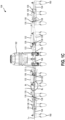
FIG. 1B is a simplified perspective view of the agricultural implement ofFIG. 1A in an extended configuration; -
FIG. 1C is a simplified rear view of the agricultural implement ofFIG. 1A in the extended configuration; -
FIG. 1D is simplified rear view of the agricultural implement ofFIG. 1A in the extended configuration when the agricultural implement is over non-level sloped and terraced ground; -
FIG. 1E is a simplified perspective view of the agricultural implement ofFIG. 1A in a folded configuration; -
FIG. 1F is a simplified rear view of the agricultural implement ofFIG. 1A in the folded configuration; -
FIG. 2 is a simplified flow chart illustrating a method of operating an agricultural implement; and -
FIG. 3 is a schematic of a computer-readable storage medium including processor-executable instructions configured to embody one or more of the methods of determining at least one flow condition within a flow channel of an agricultural machine. - The illustrations presented herein are not actual views of any agricultural machine or portion thereof, but are merely idealized representations to describe example embodiments of the present disclosure. Additionally, elements common between figures may retain the same numerical designation.
- The following description provides specific details of embodiments. However, a person of ordinary skill in the art will understand that the embodiments of the disclosure may be practiced without employing many such specific details. Indeed, the embodiments of the disclosure may be practiced in conjunction with conventional techniques employed in the industry. In addition, the description provided below does not include all elements to form a complete structure or assembly. Only those process acts and structures necessary to understand the embodiments of the disclosure are described in detail below. Additional conventional acts and structures may be used. The drawings accompanying the application are for illustrative purposes only, and are thus not drawn to scale.
- As used herein, the terms "comprising," "including," "containing," "characterized by," and grammatical equivalents thereof are inclusive or open-ended terms that do not exclude additional, unrecited elements or method steps, but also include the more restrictive terms "consisting of" and "consisting essentially of" and grammatical equivalents thereof.
- As used herein, the term "may" with respect to a material, structure, feature, or method act indicates that such is contemplated for use in implementation of an embodiment of the disclosure, and such term is used in preference to the more restrictive term "is" so as to avoid any implication that other, compatible materials, structures, features, and methods usable in combination therewith should or must be excluded.
- As used herein, the term "configured" refers to a size, shape, material composition, and arrangement of one or more of at least one structure and at least one apparatus facilitating operation of one or more of the structure and the apparatus in a predetermined way.
- As used herein, the singular forms following "a," "an," and "the" are intended to include the plural forms as well, unless the context clearly indicates otherwise.
- As used herein, the term "and/or" includes any and all combinations of one or more of the associated listed items.
- As used herein, spatially relative terms, such as "beneath," "below," "lower," "bottom," "above," "upper," "top," "front," "rear," "left," "right," and the like, may be used for ease of description to describe one element's or feature's relationship to another element(s) or feature(s) as illustrated in the figures. Unless otherwise specified, the spatially relative terms are intended to encompass different orientations of the materials in addition to the orientation depicted in the figures.
- As used herein, the term "substantially" in reference to a given parameter, property, or condition means and includes to a degree that one of ordinary skill in the art would understand that the given parameter, property, or condition is met with a degree of variance, such as within acceptable manufacturing tolerances. By way of example, depending on the particular parameter, property, or condition that is substantially met, the parameter, property, or condition may be at least 90.0% met, at least 95.0% met, at least 99.0% met, or even at least 99.9% met.
- As used herein, the term "about" used in reference to a given parameter is inclusive of the stated value and has the meaning dictated by the context (e.g., it includes the degree of error associated with measurement of the given parameter).
- As used throughout, ranges are used as shorthand for describing each and every value that is within the range. Any value within the range can be selected as the terminus of the range.
- From reading the following description it should be understood that the terms "longitudinal" and "transverse" are made in relation to a machine's (e.g., agricultural implement's) normal direction of travel. In other words, the term "longitudinal" equates to the fore-and-aft direction, whereas the term "transverse" equates to the crosswise direction, or left and right. Furthermore, the terms "axial" and "radial" are made in relation to a rotating body such as a shaft, wherein axial relates to a direction along the rotation axis and radial equates to a direction perpendicular to the rotation axis.
-
FIG. 1A is a simplified top view of atractor 102 pulling (e.g., towing) an agricultural implement 104 (also referred to as an "implement") in aforward direction 106, theforward direction 106 being an intended direction of travel of the agricultural implement 104 while being pulled by thetractor 102. Thetractor 102 includeswheels 108, an engine, and achassis 110 supported by thewheels 108 that contact a surface of theground 112. The agricultural implement 104 includes aframe 120 carrying atoolbar 150 androw units 160 connected to thetoolbar 150. Therow units 160 may be attached to thetoolbar 150 and carried by thetoolbar 150. - A
control system 114, which may include a central processing unit ("CPU"), memory, implement controller, and one or more input/output (I/O) devices 116 (e.g., a graphical user interface ("GUI") (e.g., a touch-screen interface)), is typically located in anoperator cabin 118 of thetractor 102. Thecontrol system 114 may be configured to communicate with the agricultural implement 104, such as by wired or wireless communication. Various control components (e.g., afirst actuator 132, asecond actuator 134, afirst sensor 136, and a second sensor 138) may communicate with thecontrol system 114 and control various aspects of the agricultural implement 104. For clarity and ease of understanding the description,FIG. 1A illustrates only one of each of thefirst actuator 132, thesecond actuator 134, thefirst sensor 136, and thesecond sensor 138 in communication with thecontrol system 114; however, each of thefirst actuators 132, thesecond actuators 134, thefirst sensors 136, and thesecond sensors 138 may be in communication with thecontrol system 114. In some embodiments, the I/O device 116 is configured to receive a user input, such as from an operator of thetractor 102 and/or the agricultural implement 104. For example, the user input may be a command to fold the agricultural implement 104 (e.g., such as for transport of the agricultural implement 104) and/or to extend the agricultural implement 104 (such as for a planting operation). In addition, the I/O device 116 may be configured to receive user input indicative of a predetermined setpoint of theframe 120 and/ortoolbar 150. - Each of the
row units 160 may be in operable communication with acentral hopper 162 containing seed to be planted and/or fertilizer to be applied. That is, therow units 160 may be planter and/or fertilizer row units. Theframe 120 of the agricultural implement 104 is connected to thetractor 102 by a tow hitch 164 (only a portion of which is illustrated in the view ofFIG. 1A ), which may comprise, for example, a 3-point hitch. In some embodiments, a height of thetoolbar 150 may be controlled by thetow hitch 164, as shown inU.S. Patent Application Publication 2021/0315147, "Systems comprising agricultural implements connected to lifting hitches and related control systems and methods," published October 14, 2021 . - The agricultural implement 104 may optionally be supported in the field by the
row units 160, such as at leastcenter row units 160 connected to acenter frame section 122 of theframe 120. For example, therow units 160 may each include a trench opening assembly (or "opening wheels") at a front thereof and a trench closing assembly (or "closing wheels") at a rear thereof. In use and operation, the trench opening assemblies and the trench closing assemblies may contact theground 112. In some embodiments, the agricultural implement 104 is supported by one or more wheels operably coupled to theframe 120. - The
row units 160 may be any type of ground-engaging device for planting, seeding, fertilizing, tilling, or otherwise working crops for soil, typically in rows, and may be substantially similar to the row units described in International Patent PublicationWO 2021/205245 A1, "Agricultural Implements Having Row Unit Position Sensors and at Least One Adjustable Wheel, and Related Control Systems and Methods," published October 14, 2021 . - In
FIG. 1A , theframe 120 and thetoolbar 150 are in an extended orientation. Theframe 120 and thetoolbar 150 may be in an extended configuration while performing an agricultural operation (e.g., a planting or fertilization operation) with the agricultural implement 104.FIG. 1B andFIG. 1C are a respective simplified perspective view and rear view of the agricultural implement 104 in which theframe 120 and thetoolbar 150 are in the extended configuration and on level ground;FIG. 1D is a simplified rear view of the agricultural implement 104 in which theframe 120 and thetoolbar 150 are in the extended configuration and over sloped and terraced ground; andFIG. 1E andFIG. 1F are a respective simplified perspective view and rear view of the agricultural implement 104 in which theframe 120 and thetoolbar 150 are in a folded (or retracted) configuration. - With collective reference to
FIG. 1A through FIG. 1F , theframe 120 includes acenter frame section 122 to which thetow hitch 164 and thecentral hopper 162 are operably coupled. Each lateral side of thecenter frame section 122 may be operably coupled to anintermediate frame section 124 at a first joint 126. Eachintermediate frame section 124 may be operably coupled to awing frame section 128 at asecond joint 130. As described in additional detail herein, the first joint 126 and the second joint 130 may be configured to facilitate independent lifting of the frame 120 (e.g., of thewing frame section 128 and the intermediate frame section 124) and tilting of thewing frame section 128 with respect to thecenter frame section 122. As used herein, "tilting" of theframe 120 or thewing frame section 128 means adjusting a relative angle between thewing frame section 128 and theintermediate frame section 124 and adjusting a corresponding orientation ofrow units 160 operably coupled to acenter toolbar 152 relative to an orientation ofrow units 160 operably coupled to awing toolbar 154. For example, a 0° tilt may correspond to a relative angle of 0° between thewing frame section 128 and the intermediate frame section 124 (e.g., thewing frame section 128 being substantially parallel to theintermediate frame section 128 and therow units 160 of thecenter toolbar 152 being substantially co-linear with therow units 160 of the wing toolbar 154). - The
toolbar 150 may include acenter toolbar 152 operably coupled to thecenter frame section 122, andwing toolbars 154 operably coupled to thewing frame sections 128. In some embodiments, thetoolbar 150 is not operably coupled to theintermediate frame section 124 and there are norow units 160 operably coupled to the intermediate frame section 124 (e.g., by means of a toolbar). In some embodiments, thecenter toolbar 152 is longer than thecenter frame section 122 and thewing toolbars 154 are longer than thewing frame sections 128. In some embodiments, thewing toolbars 154 are separated from (e.g., not directly connected to) thecenter toolbar 152. - A position of the
center frame section 122 may be substantially fixed with respect to the position of thecentral hopper 162 and thetow hitch 164. In use and operation, the position of thecenter frame section 122 may be substantially fixed with respect to thetractor 102. As described in additional detail herein, theintermediate frame section 124 may be configured to rotate relative to thecenter frame section 122 about the first joint 126, and thewing frame section 128 may be configured to rotate relative to theintermediate frame section 124 about thesecond joint 130. - The first joint 126 may be configured to constrain relative motion between the
intermediate frame section 124 and thecenter frame section 122 about a common axis (e.g., about the first joint 126 in and out of the page in the view ofFIG. 1C ); and the second joint 130 may be configured to constrain relative motion between theintermediate frame section 124 and thewing frame section 128 about a common axis (e.g., about the second joint 130 in and out of the page in the view ofFIG. 1C ). By way of non-limiting example, the first joint 126 and the second joint 130 may individually comprise a pin joint (e.g., a roller bearing) or a hinge joint. - As best seen in
FIG. 1C andFIG. 1F , in some embodiments, a longitudinal axis Lc of thecenter frame section 122 may be substantially parallel to a longitudinal axis LW of thewing frame section 128 when theframe 120 is in the extended configuration and onlevel ground 112 and when theframe 120 is in the folded configuration. In the extended configuration, and when the agricultural implement 104 is on substantiallylevel ground 112, the wing frame section 128 (e.g., the longitudinal axis Lw of the wing frame section 128) may be substantially parallel to the center frame section 122 (e.g., to the longitudinal axis Lc of the center frame section 122) and to theground 112. As described in additional detail herein, when theground 112 contacted by therow units 160 operably coupled to thewing toolbar 154 is not level with theground 112 contacted by therow units 160 operably coupled to thecenter toolbar 152, thewing frame section 128 may be oriented at an angle with respect to thecenter frame section 122. - With reference to
FIG. 1C ,FIG. 1D , andFIG. 1F , theintermediate frame section 124 may be oriented at an angle θ1 relative to thecenter frame section 122; and thewing frame section 128 may be oriented at an angle θ2 relative to theintermediate frame section 124. In the extended configuration, the angle θ1 between theintermediate frame section 124 and thecenter frame section 122 may be other than parallel, such as between about 150° and about 170° (or between about 10° and about 30°). In some embodiments, such as where the agricultural implement 104 is on substantiallylevel ground 112, the angle θ2 between thewing frame section 128 and theintermediate frame section 124 may be substantially the same as the angle θ1. In other embodiments, the angles θ1 and θ2 may be different when thewing frame section 128 is in an extended configuration, such as when thewing frame section 128 is overground 112 that is not on the same plane (e.g., level with) the ground over which thecenter frame section 122 travels. - Rotation of the
intermediate frame section 124 with respect to thecenter frame section 122 about the first joint 126 may cause the frame 120 (e.g., thewing frame section 128 and the intermediate frame section 124) to lift and/or lower (depending on the direction of rotation) with respect to thecenter frame section 122 and theground 112. For example, rotation of theintermediate frame section 124 relative to thecenter frame section 122 may lift or lower thewing frame section 128 and theintermediate frame section 124. During transport operations, thewing frame section 128 may be lifted (e.g., raised) to place theframe 120 and thetoolbar 150 in the folded configuration and to lift the coupledrow units 160 from theground 112. - In some embodiments, the
wing frame section 128 and theintermediate frame section 124 may be lifted and/or lowered without tilting thewing frame section 128 relative to theintermediate frame section 124. Rotation of the first joint 126 may lift and lower thewing frame section 128 and cause the orientation of thewing frame section 128 relative to theground 112 and thecenter frame section 122 to change while the longitudinal axis Lw of thewing frame section 128 remains in the same orientation with respect to the longitudinal axis LI of the intermediate frame section 124 (as long as thewing frame section 128 is not concurrently rotated about the second joint 130). - The
frame 120 may be lifted and/or lowered with afirst actuator 132. In some embodiments, thefirst actuator 132 is fixedly coupled to each of theintermediate frame section 124 and thecenter frame section 122. Thefirst actuator 132 may be operably coupled to thecenter frame section 122 at afirst connector 123 and to theintermediate frame section 124 at asecond connector 125. Thefirst connector 123 may be fixedly coupled (e.g., attached) to thecenter frame section 122 and thesecond connector 125 may be fixedly coupled to (e.g., attached to or comprise a portion of) theintermediate frame section 124. In some embodiments, thesecond connector 125 is integral with theintermediate frame section 124. In some embodiments, when theframe 120 is in an extended configuration, thefirst actuator 132 may be in an extended configuration, and when theframe 120 is in a folded configuration, thefirst actuator 132 may be in a retracted configuration. - The
first actuator 132 may include, for example, a hydraulic cylinder, an electric motor, a pneumatic actuator, or another type of actuator. In some embodiments, thefirst actuator 132 comprises a hydraulic cylinder. Thefirst actuator 132 may be configured to rotate theintermediate frame section 124 relative to thecenter frame section 122 about the first joint 126 to lift the frame 120 (e.g., theintermediate frame section 124 and the wing frame section 128). - In some embodiments, the
first actuator 132 may be configured to cause the angle θ1 between the intermediate frame section 124 (e.g., the longitudinal axis LI of the intermediate frame section 124) and the center frame section 122 (e.g., the longitudinal axis Lc of the center frame section 122) to change. For example, extension of the first actuator 132 (e.g., extending the piston out of the cylinder tube) may cause the angle θ1 to increase and retraction of thefirst actuator 132 may cause the angle θ1 to decrease. - In some embodiments, the
first actuator 132 may be configured to cause the angle θ1 between thecenter frame section 122 and theintermediate frame section 124 to change by up to at least about 60°, such as up to about least about 75°, up to about 90°, or even up to about 100° between the extended configuration and the retracted configuration. Of course, the disclosure is not so limited, and the amount that thefirst actuator 132 may cause the angle θ1 to change may be different than that described. - With reference to
FIG. 1B through FIG. 1F , rotation of thewing frame section 128 relative to theintermediate frame section 124 about the second joint 130 may change the angle Θz to tilt thewing frame section 128 with respect to theintermediate frame section 124. In addition, rotation of thewing frame section 128 relative to theintermediate frame section 124 may also change an angle between thewing frame section 128 and thecenter frame section 122. Thewing frame section 128 may be tilted up or down based on the direction of rotation of thesecond joint 130. In some embodiments, the tilt of thewing frame section 128 may be independently adjusted relative to the lift of theframe 120 to contact unlevel ground withrow units 160 operably coupled to thewing toolbar 154. - In some embodiments, the
wing frame section 128 may be tilted with asecond actuator 134. Thesecond actuator 134 may be operably coupled to thewing frame section 128 at athird connector 129 and to theintermediate frame section 124 at thesecond connector 125. In some embodiments, thesecond actuator 134 is fixedly coupled to each of theintermediate frame section 124 and thewing frame section 128. Thethird connector 129 may be fixedly coupled (e.g., attached) to thewing frame section 128. In some embodiments, when theframe 120 is in an extended configuration, thesecond actuator 134 may be in a retracted configuration, and when theframe 120 is in a folded configuration, thesecond actuator 132 may be in an extended configuration. In some embodiments, thesecond actuator 134 may be configured to cause the angle θ2 to change by up to at least about 45°, such as up to at least about 60°. However, the disclosure is not so limited, and the amount that thesecond actuator 134 may cause the angle θ2 to change may be different than that described. - In some embodiments, the
wing frame section 128 may be configured to be tilted downwards, such as when thewing frame section 128 is located overground 112 that is relatively lower than theground 112 over which thecenter frame section 122 is disposed; and thewing frame section 128 may be configured to be tilted upwards, such as when thewing frame section 128 is located overground 112 that is relatively higher than theground 112 over which thecenter frame section 122 is disposed. For example, thesecond actuator 134 may be extended to cause thewing frame section 128 to rotate downwards relative to thecenter frame section 122 and thesecond actuator 134 may be retracted to cause thewing frame section 128 to rotate upwards relative to thecenter frame section 122. For example, with reference toFIG. 1D , when the agricultural implement 104 is on slopedground 112 and/orterraced ground 112, the longitudinal axis LW of thewing frame section 128 may not be parallel to the longitudinal axis Lc of thecenter frame section 122 when theframe 120 is in the extended configuration. For example, when the agricultural implement 104 is on sloped ground 112 (e.g., such as illustrated on the left side ofFIG. 1D ), thewing frame section 128 may be tilted downwards relative to theintermediate frame section 124 such that therow units 160 operably coupled to thewing toolbar 154contact ground 112 that is lower than theground 112 over thecenter frame section 122 and thecenter toolbar 152. Similarly, if the slope of theground 112 was in the opposite direction, thewing frame section 128 may be tilted upwards relative to theintermediate frame section 124 such that therow units 160 operably coupled to thewing toolbar 154contact ground 112 that is higher than theground 112 over thecenter frame section 122 and thecenter toolbar 152. - With continued reference to
FIG. 1D , when the agricultural implement 104 is on terraced ground (e.g., such as illustrated on the right side ofFIG. 1D ), thewing frame section 128 may be tilted upwards relative to theintermediate frame section 124 such that therow units 160 operably coupled to thewing toolbar 154contact ground 112 that is higher than theground 112 over thecenter frame section 122 and thecenter toolbar 152. Similarly, if the terraced ground on the right side ofFIG. 1D was lower than theground 112 over thecenter frame section 122, thewing frame section 128 may be tilted downwards relative to theintermediate frame section 124 such that therow units 160 operably coupled to thewing toolbar 154contact ground 112 that is lower than theground 112 over thecenter frame section 122 and thecenter toolbar 152. - Each of the
first actuator 132 and thesecond actuator 134 may be independently controlled to independently raise/lower theframe 120 and tilt thewing frame section 128, respectively. For example, during a planting operation, thewing frame section 128 may be tilted upwards or downwards relative to thecenter frame section 122 to follow the contour of theground 112 without lifting thewing frame section 128. During a folding operation (e.g., prior to transporting the agricultural implement 104 to/from an agricultural field), thefirst actuator 132 may cause theframe 120 to be lifted and thesecond actuator 134 may cause thewing frame section 128 to remain substantially parallel to thecenter frame section 122 and/or may cause thewing frame section 128 to tilt without contactingrow units 160 operably coupled to thecenter toolbar 152 withrow units 160 operably coupled to thewing toolbar 154. - In some embodiments, each of the
first actuator 132 and thesecond actuator 134 are individually coupled to separate hydraulic circuits independent of one another. In other words, the inlet pressure and the outlet pressure of each of thefirst actuator 132 and thesecond actuator 134 may be independently coupled to different hydraulic circuits, which may be controlled by thecontrol system 114. - In some embodiments, a
first sensor 136 may be operably coupled to the first joint 126, and asecond sensor 138 may be operably coupled to thesecond joint 130. Thefirst sensor 136 may be used to determine a lift of theframe 120 and may be configured to determine a position of theintermediate frame section 124 relative to the center frame section 122 (e.g., the angle θ1 between thecenter frame section 122 and theintermediate frame section 124 and/or a degree of actuation of the first actuator 132); and thesecond sensor 138 may be used to determine a tilt of thewing frame section 128 and may be configured to determine a position of thewing frame section 128 relative to the intermediate frame section 124 (e.g., the corresponding angle θ2 between thewing frame section 128 and theintermediate frame section 124 and/or a degree of actuation of the second actuator 134). In some embodiments, thesensors wing frame section 128 relative to thecenter frame section 122, depending on the current lift of theframe 120 and the tilt of thewing frame section 128. In some embodiments, thesensors control system 114 to independently adjust the lift of theframe 120 and the tilt of thewing frame section 128. Independently controlling the lift and the tilt of thewing frame section 128 may facilitate providing a closer spacing between neighboringrow units 160 compared to other agricultural implements in which the wing toolbars are linked to the center toolbar (e.g., such as with rephasing cylinders and/or linkages) and/or provide clearance between neighboringrow units 160 and thetoolbar 150 while adjusting the lift and/or tilt. - In some embodiments, the
first sensor 136 includes a rotary sensor configured to measure the rotation of first joint 126 (corresponding to the angle θ1 between thecenter frame section 122 and the intermediate frame section 124) and may be connected to the first joint 126, such as at a pivot point of theintermediate frame section 124; and thesecond sensor 138 includes a rotary sensor configured to measure the rotation of the second joint 130 (corresponding to the angle θ2 between thewing frame section 128 and the intermediate frame section 124) and may be connected to the second joint 130, such as a pivot point of thewing frame section 128. - In some embodiments, each of the
first sensor 136 and thesecond sensor 138 individually include a rotary sensor (e.g., a rotary position sensor), such as a rotary potentiometer, a Hall-effect sensor, a rotary variable differential transducer (RVDT) sensor, or an inductive-based rotary sensor. - While the
first sensor 136 and thesecond sensor 138 are depicted as being operably coupled to the respective first joint 126 and second joint 130, the disclosure is not so limited. In other embodiments, each of thefirst sensor 136 and thesecond sensor 138 may individually be operably coupled to the respectivefirst actuator 132 and thesecond actuator 134 and configured to determine a displacement and/or a position of thefirst actuator 132 and the second actuator 134 (e.g., a position of the piston of each of thefirst actuator 132 and the second actuator 134). By way of non-limiting example, thefirst sensor 136 and thesecond sensor 138 may individually include a linear displacement transducer (LDT) sensor, a linear position sensor, a magnetoresistive linear displacement transducer, a linear variable differential transformer (LVDT), or another type of position sensor. - In other embodiments, the
first sensor 136 and thesecond sensor 138 may individually be operably coupled to, for example, one or more of thecenter frame section 122, theintermediate frame section 124, and thewing frame section 128 and configured to determine a distance to another component of the frame 120 (e.g., another of thecenter frame section 122, theintermediate frame section 124, and the wing frame section 128). By way of non-limiting example, thefirst sensor 136 and thesecond sensor 138 may individually include a non-contact sensor, for example, an optical sensor, an ultrasonic transducer, an RF (radio frequency) sensor, lidar, radar, etc. Such sensors are described in, for example,U.S. Patent 10,874,042, "Seed Trench Depth Detection Systems," granted December 29, 2020 - In some embodiments, the
control system 114 may be in operable communication with each of thefirst actuator 132, thesecond actuator 134, thefirst sensor 136, and thesecond sensor 138, such as by wired or wireless communication. For example, thecontrol system 114 may be configured to receive sensor information from thefirst sensor 136 and thesecond sensor 138 indicative of the lift and tilt of theframe 120. The sensor information may include, for example, a rotation information of the first joint 126 and the second joint 130, a position of the respective pistons of thefirst actuator 132 and thesecond actuator 134, and/or a position (e.g., a distance) of one or more of thecenter frame section 122, theintermediate frame section 124, and thewing frame section 128 from the other of thecenter frame section 122, theintermediate frame section 124, and thewing frame section 128. - The
control system 114 may be configured to provide control signals to each of thefirst actuator 132 and thesecond actuator 134 independently of one another to control a respective orientation of the frame 120 (e.g., a lift of the frame 120) and a tilt of thewing frame section 128, as shown by dashed lines inFIG. 1A . For example, responsive to receiving an input (e.g., such as from a user of the agricultural implement 104 at the I/O device 116), thecontrol system 114 may be configured to provide control instructions to one or both of thefirst actuator 132 and thesecond actuator 134 to control an amount of the respective lift and/or tilt. In some embodiments, responsive to receiving a folding instruction at the I/O device 116, thecontrol system 114 may cause thefirst actuator 132 to lift theframe 120, followed by causing thesecond actuator 134 to tilt thewing frame section 128 to keep thewing frame section 128 substantially parallel to thecenter frame section 122, as described in additional detail herein. In addition, responsive to receiving instructions at the I/O device 116 to extend theframe 120, thecontrol system 114 may be configured to cause thefirst actuator 132 to lift theframe 120, followed by causing thesecond actuator 134 to tilt thewing frame section 128 to increase the angle θ2 and maintain thewing frame section 128 substantially parallel to thecenter frame section 122 as the angle θ1 changes during the lowering operation. In some embodiments, thecontrol system 114 may be configured to cause thefirst actuator 132 and thesecond actuator 134 to cause therow units 160 operably coupled to thewing toolbars 154 to contact (e.g., engage) theground 112 at substantially the same time. In some embodiments, thecontrol system 114 is configured to synchronously stack thewing frame sections 128 above thecenter frame section 122 while maintaining the second angle θ2 at the second joint 130 to be substantially the same as the first angle θ1 at the first joint 126. - In some embodiments, the
control system 114 may be configured to cause thefirst actuator 132 and thesecond actuator 134 to cause therow units 160 operably coupled to thewing toolbars 154 to contact (e.g., engage) theground 112 at substantially the same time. In some embodiments, thecontrol system 114 is configured to facilitate lifting of theframe 120 and tilting of thewing frame section 128 by different amounts and/or at different rates. For example, thecontrol system 114 may be configured to adjust the lift of theframe 120 by a different amount (e.g., a different percentage) than an amount of adjustment of the tilt of the wing frame section 128 (e.g., a different percentage). By way of non-limiting example, thecontrol system 114 may be configured to cause thefirst actuator 132 to move a different amount (e.g., a different percentage of an operating range of the first actuator 132) than thesecond actuator 134. In some embodiments, thecontrol system 114 is configured to cause thefirst actuator 132 to cause theintermediate frame section 124 to rotate relative to thecenter frame section 122 by a different (e.g., a greater, a lesser) percentage of a range of motion of theintermediate frame section 124 about the first joint 126 than thecontrol system 114 causes thesecond actuator 134 to cause thewing frame section 128 to rotate relative to theintermediate frame section 124 about thesecond joint 130. In other words, thecontrol system 114 may be configured to cause the first angle θ1 to be different than the second angle θ2 by causing at least one of thefirst actuator 132 and thesecond actuator 134 to change the respective first angle θ1 and second angle θ2. - In some embodiments, a user may input a desired configuration for the
frame 120 and thetoolbar 150, such as at the I/O device 116. Based on the selected configuration, thefirst actuator 132 and thesecond actuator 134 may cause theframe 120 to move to the desired configuration, such as by moving thewing frame section 128 at a different time, at a different rate, and/or by a different amount (e.g., a different angle) than theintermediate frame section 124. - Rotating the
wing frame section 128 and theintermediate frame section 124 by different amounts (e.g., different percentages) may provide additional clearance betweenrow units 160 and other components of the agricultural implement 104 (e.g.,other row units 160, the frame 120), facilitating a decrease in the row spacing of therow units 160 without inadvertently contacting neighboringrow units 160 and/or thecenter frame section 122 withrow units 160 operably coupled to thewing toolbar 154 during rotation of theintermediate frame section 124 and/or rotation of thewing frame section 128. -
FIG. 2 is a simplified flow chart illustrating amethod 200 of folding or extending the agricultural implement 104. Themethod 200 includes rotating theintermediate frame section 124 relative to thecenter frame section 122, as shown inact 202. Rotating theintermediate frame section 124 relative to thecenter frame section 122 may adjust the lift of theframe 120. Adjusting the lift of theframe 120 includes raising or lowering theframe 120, such as by actuating thefirst actuator 132 to adjust the angle θ1 between thecenter frame section 122 and theintermediate frame section 124. - Responsive to rotating the intermediate frame section relative to the
center frame section 122, themethod 200 includes determining a position of theintermediate frame section 124 relative to thecenter frame section 122, as shown inact 204. Determining the relative position of theintermediate frame section 124 may include determining the angle θ1 between thecenter frame section 122 and theintermediate frame section 124. For example, the angle θ1 may be determined by sensing the angle θ1 with thefirst sensor 136. In other embodiments, determining the position of theintermediate frame section 124 relative to thecenter frame section 122 includes sensing the position of thefirst actuator 132 with the first sensor 136 (e.g., determining the linear displacement of the first actuator 132). In some embodiments, determining the position of theintermediate frame section 124 relative to thecenter frame section 122 includes determining the lift of theframe 120. - Responsive to determining position of the
intermediate frame section 124 relative to thecenter frame section 122, themethod 200 further includes determining a position of thewing frame section 128 relative to theintermediate frame section 124, as shown inact 206. Determining the position of thewing frame section 128 relative to theintermediate frame section 124 may include sensing the angle Θz between thewing frame section 128 and theintermediate frame section 124. For example, the angle Θz may be determined by sensing the angle Θz with thesecond sensor 138. In other embodiments, determining the position of thewing frame section 128 relative to theintermediate frame section 124 includes sensing the position of thesecond actuator 134 with the second sensor 138 (e.g., determining the linear displacement of the second actuator 134). In some embodiments, determining the position of thewing frame section 128 relative to theintermediate frame section 124 includes determining the tilt of thewing frame section 128. - The
method 200 may further include adjusting the position of thewing frame section 128 differently than theintermediate frame section 128, such as by at least one of a different rate and a different amount than theintermediate frame section 124, as shown inact 208. For example, act 208 may include adjusting the position of thewing frame section 128 relative to the intermediate frame section 124 (e.g., the second angle θ2) to be different than the position of theintermediate frame section 124 relative to the center frame section 122 (e.g., the first angle θ1). In other words, act 208 may include adjusting the second angle θ2 differently than the first angle θ1 (e.g., adjusting thewing frame section 128 to be at a position other than parallel (e.g., non-parallel) to the center frame section 122). In some embodiments, act 208 includes changing the second angle θ2 at a different rate than the first angle θ1. Adjusting the second angle θ2 at a different rate than the first angle θ1 may include changing the position of thesecond actuator 134 by a different amount and/or a different rate than the position of thefirst actuator 132. For example, thesecond actuator 134 may be adjusted by a different percentage of a total displacement than thefirst actuator 132 is displaced to cause the second angle θ2 to be different than the first angle θ1. In some embodiments, the ratio of change of thesecond actuator 134 may be different than the ratio of the change of thefirst actuator 132. In other words, the percentage of total displacement of thefirst actuator 132 may be different than the percentage of total displacement of thesecond actuator 134. In some embodiments, act 208 includes adjusting the position of thewing frame section 128 to be oriented at a position other than parallel (e.g., non-parallel) to thecenter frame section 122. - In some embodiments, folding the
frame 120 includes adjusting the height of the frame 120 (e.g., by actuation of the first actuator 132), followed by adjusting the tilt of the wing frame section 128 (e.g., by actuation of the second actuator 134). In some such embodiments, the tilt of thewing frame section 128 may follow the lift of theframe 120. Similarly, when adjusting theframe 120 from a folded configuration to an extended configuration, the lift of theframe 120 may be decreased, followed by adjustment of the tilt of thewing frame section 128 by a different amount. In other words, in some embodiments, themethod 200 includes determining a position of theintermediate frame section 124 relative to the center frame section 122 (e.g., determining the first angle θ1, and causing thesecond actuator 134 to change the position of thewing frame section 128 relative to theintermediate frame section 124 while keeping the second angle θ2 different than the first angle θ1 at least for a duration. -
FIG. 3 is a schematic view of acomputer device 302. In some embodiments, the control system 114 (FIG. 1A ) includes a computer device such as thecomputer device 302 ofFIG. 3 . Thecomputer device 302 may include acommunication interface 304, at least oneprocessor 306, amemory 308, astorage device 310, an input/output device 312, and abus 314. Thecomputer device 302 may be used to implement various functions, operations, acts, processes, and/or methods disclosed herein, such as themethod 200. - The
communication interface 304 may include hardware, software, or both. Thecommunication interface 304 may provide one or more interfaces for communication (such as, for example, packet-based communication) between thecomputer device 302 and one or more other computing devices or networks (e.g., a server). As an example, and not by way of limitation, thecommunication interface 304 may include a network interface controller (NIC) or network adapter for communicating with an Ethernet or other wire-based network or a wireless NIC (WNIC) or wireless adapter for communicating with a wireless network, such as a Wi-Fi. - The at least one
processor 306 may include hardware for executing instructions, such as those making up a computer program. By way of non-limiting example, to execute instructions, the at least oneprocessor 306 may retrieve (or fetch) the instructions from an internal register, an internal cache, thememory 308, or thestorage device 310 and decode and execute them to execute instructions. In some embodiments, the at least oneprocessor 306 includes one or more internal caches for data, instructions, or addresses. The at least oneprocessor 306 may include one or more instruction caches, one or more data caches, and one or more translation look aside buffers (TLBs). Instructions in the instruction caches may be copies of instructions in thememory 308 or thestorage device 310. - The
memory 308 may be coupled to the at least oneprocessor 306. Thememory 308 may be used for storing data, metadata, and programs for execution by the processor(s). Thememory 308 may include one or more of volatile and non-volatile memories, such as Random-Access Memory ("RAM"), Read-Only Memory ("ROM"), a solid state disk ("SSD"), Flash, Phase Change Memory ("PCM"), or other types of data storage. Thememory 308 may be internal or distributed memory. - The
storage device 310 may include storage for storing data or instructions. As an example, and not by way of limitation,storage device 310 may include a non-transitory storage medium described above. Thestorage device 310 may include a hard disk drive (HDD), Flash memory, an optical disc, a magneto-optical disc, magnetic tape, or a Universal Serial Bus (USB) drive or a combination of two or more of these. Thestorage device 310 may include removable or non-removable (or fixed) media, where appropriate. Thestorage device 310 may be internal or external to thestorage device 310. In one or more embodiments, thestorage device 310 is non-volatile, solid-state memory. In other embodiments, thestorage device 310 includes read-only memory (ROM). Where appropriate, this ROM may be mask programmed ROM, programmable ROM (PROM), erasable PROM (EPROM), electrically erasable PROM (EEPROM), electrically alterable ROM (EAROM), or Flash memory or a combination of two or more of these. - The
storage device 310 may include machine-executable code stored thereon. Thestorage device 310 may include, for example, a non-transitory computer-readable storage medium. The machine-executable code includes information describing functional elements that may be implemented by (e.g., performed by) the at least oneprocessor 306. The at least oneprocessor 306 is adapted to implement (e.g., perform) the functional elements described by the machine-executable code. In some embodiments the at least oneprocessor 306 may be configured to perform the functional elements described by the machine-executable code sequentially, concurrently (e.g., on one or more different hardware platforms), or in one or more parallel process streams. - When implemented by the at least one
processor 306, the machine-executable code is configured to adapt the at least oneprocessor 306 to perform operations of embodiments disclosed herein. For example, the machine-executable code may be configured to adapt the at least oneprocessor 306 to perform at least a portion or a totality of themethod 200 ofFIG. 2 . As another example, the machine-executable code may be configured to adapt the at least oneprocessor 306 to perform at least a portion or a totality of the operations discussed for the agricultural implement 104 ofFIG. 1A through FIG. 1E . As a specific, non-limiting example, the machine-executable code may be configured to adapt the at least oneprocessor 306 to cause the agricultural implement 104 to fold and/or extend by adjusting the lift of theframe 120 and maintaining thewing frame sections 128 substantially parallel to thecenter frame section 122 while adjusting the lift of theframe 120. In another non-limiting example, the machine-executable code may be configured to adapt the at least oneprocessor 306 to independently control thefirst actuator 132 and thesecond actuator 134. - The input/
output device 312 may correspond to the input/output device 116 ofFIG. 1A and may allow an operator of the agricultural implement 104 to provide input to, receive output from, thecomputer device 302. The input/output device 312 may include a mouse, a keypad or a keyboard, a joystick, a touch screen, a camera, an optical scanner, network interface, modem, other known I/O devices, or a combination of such I/O interfaces. - In some embodiments, the bus 314 (e.g., a Controller Area Network (CAN) bus, an ISOBUS (ISO 11783 Compliant Implement Control)) may include hardware, software, or both that couples components of
computer device 302 to each other and to external components. - All references cited herein are incorporated herein in their entireties. If there is a conflict between definitions herein and in an incorporated reference, the definition herein shall control.
- While the present disclosure has been described herein with respect to certain illustrated embodiments, those of ordinary skill in the art will recognize and appreciate that it is not so limited. Rather, many additions, deletions, and modifications to the illustrated embodiments may be made without departing from the scope of the disclosure as hereinafter claimed, including legal equivalents thereof. In addition, features from one embodiment may be combined with features of another embodiment while still being encompassed within the scope as contemplated by the inventors. Further, embodiments of the disclosure have utility with different and various machine types and configurations.
Claims (15)
- An agricultural implement, comprising:a center frame section;an intermediate frame section pivotally coupled to a side of the center frame section;a wing frame section pivotally coupled to the intermediate frame section;a first actuator operably coupled to the center frame section and the intermediate frame section;a second actuator operably coupled to the wing frame section and the intermediate frame section;a first sensor configured to sense a position of the intermediate frame section relative to the center frame section;a second sensor configured to sense a position of the wing frame section relative to the intermediate frame section; anda control system configured to independently control the first actuator and the second actuator to travel by a different percentage of a total displacement based on the sensed positions of the intermediate frame section and the wing frame section.
- The agricultural implement of claim 1, wherein the first sensor comprises:a rotary sensor configured to determine an angle between the center frame section and the intermediate frame section; ora linear sensor configured to determine a position of the first actuator.
- The agricultural implement of any one of claims 1 through 2, wherein the control system is configured to cause the second actuator to rotate the wing frame section to be substantially non-parallel to the center frame section.
- The agricultural implement of any one of claims 1 through 3, wherein the control system is configured to cause the second actuator to cause an angle between the wing frame section and the intermediate frame section to be different than an angle between the intermediate frame section and the center frame section.
- The agricultural implement of any one of claims 1 through 4, wherein the control system is configured to cause the second actuator to adjust the position of wing frame section relative to the intermediate frame section after causing the first actuator to adjust the position of the intermediate frame section relative to the center frame section.
- The agricultural implement of any one of claims 1 through 5, wherein:the first actuator comprises a first hydraulic cylinder; andthe second actuator comprises a second hydraulic cylinder.
- The agricultural implement of any one of claims 1 through 6, wherein each of the first actuator and the second actuator are operably coupled to the intermediate frame section at a connector.
- The agricultural implement of any one of claims 1 through 7, further comprising:a wing tool bar operably coupled to the wing frame section; androw units operably coupled to the wing frame section.
- The agricultural implement of any one of claims 1 through 8, wherein the control system is configured to cause second actuator to change the position of the wing frame section at a different rate than the first actuator changes the position of the intermediate frame section.
- The agricultural implement of any one of claims 1 through 9, wherein the first actuator is operably coupled to the center frame section and the intermediate frame section.
- A method of operating an agricultural implement, the method comprising:causing a first actuator to rotate an intermediate frame section relative to a center frame section;determining, with a first sensor, a position of the intermediate frame section relative to the center frame section;determining, with a second sensor, a position of a wing frame section relative to the intermediate frame section; andcausing a second actuator operably coupled to the wing frame section and the intermediate frame section to change an angle between the wing frame section and the intermediate frame section to be different than an angle between the intermediate frame section and the center frame section.
- The method of claim 11, wherein determining, with a first sensor, a position of the intermediate frame section relative to the center frame section comprises:measuring the angle between the intermediate frame section and the center frame section; ormeasuring a linear displacement of the first actuator.
- The method of any one of claims 11 through 12, wherein changing an angle between the wing frame section and the intermediate frame section comprises:changing the angle between the wing frame section and the intermediate frame section at a different rate than changing the angle between the intermediate frame section and the center frame section; and/orcausing the second actuator to change the angle between the wing frame section and the intermediate frame section after causing the first actuator to rotate the intermediate frame section relative to the center frame section.
- The method of any one of claims 11 through 13, wherein changing an angle between the wing frame section and the intermediate frame section comprises changing the angle between the wing frame section and the intermediate frame section at the same time as causing the first actuator to rotate the intermediate frame section relative to the center frame section.
- A control system for an agricultural implement, the control system comprising:at least one processor; andat least one non-transitory computer-readable storage medium storing instructions thereon that, when executed by the at least one processor, cause the control system to:cause a first actuator to rotate an intermediate frame section relative to a center frame section by a first amount;receive, from a first sensor, an indication of a position of the intermediate frame section relative to the center frame section;receive, from a second sensor, an indication of a position of a wing frame section relative to the intermediate frame section; andcause a second actuator to rotate the wing frame section relative to the intermediate frame section by a second amount different than the first amount, at a different time than the intermediate frame section is rotated relative to the center frame section, or both.
Applications Claiming Priority (1)
| Application Number | Priority Date | Filing Date | Title |
|---|---|---|---|
| US202363604342P | 2023-11-30 | 2023-11-30 |
Publications (1)
| Publication Number | Publication Date |
|---|---|
| EP4562991A1 true EP4562991A1 (en) | 2025-06-04 |
Family
ID=93258984
Family Applications (1)
| Application Number | Title | Priority Date | Filing Date |
|---|---|---|---|
| EP24208254.3A Pending EP4562991A1 (en) | 2023-11-30 | 2024-10-23 | Agricultural implements and related methods and systems |
Country Status (2)
| Country | Link |
|---|---|
| US (1) | US20250176451A1 (en) |
| EP (1) | EP4562991A1 (en) |
Citations (8)
| Publication number | Priority date | Publication date | Assignee | Title |
|---|---|---|---|---|
| US8807236B2 (en) | 2010-06-30 | 2014-08-19 | Cnh Industrial Canada, Ltd. | Agricultural implement incorporating stack-fold planter |
| FR3007240A1 (en) * | 2013-06-25 | 2014-12-26 | Kuhn Sa | HARVESTING MACHINE HAVING CONTROL OF THE HARVESTING HEIGHT OF A HARVESTING TOOL |
| US20170118901A1 (en) * | 2014-06-13 | 2017-05-04 | Väderstad Holding Ab | Agricultural implement having frame sections moveable relative each other and method of determining mutual position of frame sections |
| US20190223370A1 (en) * | 2013-11-13 | 2019-07-25 | Cnh Industrial America Llc | Agricultural tillage implement fold sequence control |
| US10874042B2 (en) | 2016-05-13 | 2020-12-29 | Precision Planting Llc | Seed trench depth detection systems |
| WO2021205245A1 (en) | 2020-04-08 | 2021-10-14 | Agco Corporation | Agricultural implements having row unit position sensors and at least one adjustable wheel, and related control systems and methods |
| US20210315147A1 (en) | 2020-04-08 | 2021-10-14 | Agco Corporation | Systems comprising agricultural implements connected to lifting hitches and related control systems and methods |
| US11229152B2 (en) | 2017-05-12 | 2022-01-25 | Deere & Company | Ground-engaging implement with lateral position adjustment |
-
2024
- 2024-10-17 US US18/918,797 patent/US20250176451A1/en active Pending
- 2024-10-23 EP EP24208254.3A patent/EP4562991A1/en active Pending
Patent Citations (8)
| Publication number | Priority date | Publication date | Assignee | Title |
|---|---|---|---|---|
| US8807236B2 (en) | 2010-06-30 | 2014-08-19 | Cnh Industrial Canada, Ltd. | Agricultural implement incorporating stack-fold planter |
| FR3007240A1 (en) * | 2013-06-25 | 2014-12-26 | Kuhn Sa | HARVESTING MACHINE HAVING CONTROL OF THE HARVESTING HEIGHT OF A HARVESTING TOOL |
| US20190223370A1 (en) * | 2013-11-13 | 2019-07-25 | Cnh Industrial America Llc | Agricultural tillage implement fold sequence control |
| US20170118901A1 (en) * | 2014-06-13 | 2017-05-04 | Väderstad Holding Ab | Agricultural implement having frame sections moveable relative each other and method of determining mutual position of frame sections |
| US10874042B2 (en) | 2016-05-13 | 2020-12-29 | Precision Planting Llc | Seed trench depth detection systems |
| US11229152B2 (en) | 2017-05-12 | 2022-01-25 | Deere & Company | Ground-engaging implement with lateral position adjustment |
| WO2021205245A1 (en) | 2020-04-08 | 2021-10-14 | Agco Corporation | Agricultural implements having row unit position sensors and at least one adjustable wheel, and related control systems and methods |
| US20210315147A1 (en) | 2020-04-08 | 2021-10-14 | Agco Corporation | Systems comprising agricultural implements connected to lifting hitches and related control systems and methods |
Also Published As
| Publication number | Publication date |
|---|---|
| US20250176451A1 (en) | 2025-06-05 |
Similar Documents
| Publication | Publication Date | Title |
|---|---|---|
| US20230263085A1 (en) | Implement contouring toolbar | |
| US20250000002A1 (en) | Automated leveling and depth control system of a work machine and method thereof | |
| US12382849B2 (en) | Systems comprising agricultural implements connected to lifting hitches and related control systems and methods | |
| US20240188472A1 (en) | Agricultural implements having row unit position sensors and at least one adjustable wheel, and related control systems and methods | |
| US11696523B2 (en) | System and method for hydraulically leveling a multi-wing agricultural implement | |
| US12364186B2 (en) | Agricultural implements having row unit position sensors and a rotatable implement frame, and related control systems and methods | |
| CA2956648C (en) | Tool bar pivot hinge assembly for an agricultural implement | |
| US10912244B2 (en) | Enhanced resolution fore/aft leveling of a towable tillage implement | |
| EP4562990A1 (en) | Agricultural implements and related methods and systems | |
| US20250176451A1 (en) | Agricultural Implements and Related Methods and Systems | |
| US20230270039A1 (en) | Agricultural implements having row unit position sensors and actuators configured to rotate toolbars, and related control systems and methods | |
| CA3049055A1 (en) | Frame assembly and actuator arrangement for agricultural implements | |
| US11304353B2 (en) | Closed-loop proportional position control of an implement stabilizer wheel | |
| WO2024105474A1 (en) | Agricultural implement and related method | |
| RU2807349C2 (en) | System for aligning canopy carrying seeding units against terrain of the ground and control system for aligning tool containing frame element and canopy to terrain of the ground | |
| WO2026069084A1 (en) | Method of operating a seedbed preparation or seeding implement coupled to a tractor and related systems | |
| US20240147887A1 (en) | Joint assembly for an agricultural implement |
Legal Events
| Date | Code | Title | Description |
|---|---|---|---|
| PUAI | Public reference made under article 153(3) epc to a published international application that has entered the european phase |
Free format text: ORIGINAL CODE: 0009012 |
|
| STAA | Information on the status of an ep patent application or granted ep patent |
Free format text: STATUS: THE APPLICATION HAS BEEN PUBLISHED |
|
| AK | Designated contracting states |
Kind code of ref document: A1 Designated state(s): AL AT BE BG CH CY CZ DE DK EE ES FI FR GB GR HR HU IE IS IT LI LT LU LV MC ME MK MT NL NO PL PT RO RS SE SI SK SM TR |
|
| STAA | Information on the status of an ep patent application or granted ep patent |
Free format text: STATUS: REQUEST FOR EXAMINATION WAS MADE |
|
| 17P | Request for examination filed |
Effective date: 20251204 |