EP4561276A1 - Decorative member, housing of electronic device, and electronic device - Google Patents
Decorative member, housing of electronic device, and electronic device Download PDFInfo
- Publication number
- EP4561276A1 EP4561276A1 EP23844930.0A EP23844930A EP4561276A1 EP 4561276 A1 EP4561276 A1 EP 4561276A1 EP 23844930 A EP23844930 A EP 23844930A EP 4561276 A1 EP4561276 A1 EP 4561276A1
- Authority
- EP
- European Patent Office
- Prior art keywords
- decorative member
- grating
- grating portions
- square
- texture layer
- Prior art date
- Legal status (The legal status is an assumption and is not a legal conclusion. Google has not performed a legal analysis and makes no representation as to the accuracy of the status listed.)
- Pending
Links
Images




Classifications
-
- G—PHYSICS
- G02—OPTICS
- G02B—OPTICAL ELEMENTS, SYSTEMS OR APPARATUS
- G02B5/00—Optical elements other than lenses
- G02B5/18—Diffraction gratings
- G02B5/1814—Diffraction gratings structurally combined with one or more further optical elements, e.g. lenses, mirrors, prisms or other diffraction gratings
- G02B5/1819—Plural gratings positioned on the same surface, e.g. array of gratings
-
- B—PERFORMING OPERATIONS; TRANSPORTING
- B32—LAYERED PRODUCTS
- B32B—LAYERED PRODUCTS, i.e. PRODUCTS BUILT-UP OF STRATA OF FLAT OR NON-FLAT, e.g. CELLULAR OR HONEYCOMB, FORM
- B32B7/00—Layered products characterised by the relation between layers; Layered products characterised by the relative orientation of features between layers, or by the relative values of a measurable parameter between layers, i.e. products comprising layers having different physical, chemical or physicochemical properties; Layered products characterised by the interconnection of layers
- B32B7/02—Physical, chemical or physicochemical properties
- B32B7/023—Optical properties
-
- B—PERFORMING OPERATIONS; TRANSPORTING
- B44—DECORATIVE ARTS
- B44F—SPECIAL DESIGNS OR PICTURES
- B44F1/00—Designs or pictures characterised by special or unusual light effects
- B44F1/02—Designs or pictures characterised by special or unusual light effects produced by reflected light, e.g. matt surfaces, lustrous surfaces
-
- B—PERFORMING OPERATIONS; TRANSPORTING
- B44—DECORATIVE ARTS
- B44F—SPECIAL DESIGNS OR PICTURES
- B44F1/00—Designs or pictures characterised by special or unusual light effects
- B44F1/08—Designs or pictures characterised by special or unusual light effects characterised by colour effects
- B44F1/14—Iridescent effects
-
- G—PHYSICS
- G02—OPTICS
- G02B—OPTICAL ELEMENTS, SYSTEMS OR APPARATUS
- G02B27/00—Optical systems or apparatus not provided for by any of the groups G02B1/00 - G02B26/00, G02B30/00
- G02B27/42—Diffraction optics, i.e. systems including a diffractive element being designed for providing a diffractive effect
- G02B27/4233—Diffraction optics, i.e. systems including a diffractive element being designed for providing a diffractive effect having a diffractive element [DOE] contributing to a non-imaging application
-
- G—PHYSICS
- G02—OPTICS
- G02B—OPTICAL ELEMENTS, SYSTEMS OR APPARATUS
- G02B5/00—Optical elements other than lenses
- G02B5/04—Prisms
- G02B5/045—Prism arrays
-
- G—PHYSICS
- G02—OPTICS
- G02B—OPTICAL ELEMENTS, SYSTEMS OR APPARATUS
- G02B5/00—Optical elements other than lenses
- G02B5/18—Diffraction gratings
-
- G—PHYSICS
- G02—OPTICS
- G02B—OPTICAL ELEMENTS, SYSTEMS OR APPARATUS
- G02B5/00—Optical elements other than lenses
- G02B5/18—Diffraction gratings
- G02B5/1861—Reflection gratings characterised by their structure, e.g. step profile, contours of substrate or grooves, pitch variations, materials
-
- H—ELECTRICITY
- H04—ELECTRIC COMMUNICATION TECHNIQUE
- H04M—TELEPHONIC COMMUNICATION
- H04M1/00—Substation equipment, e.g. for use by subscribers
- H04M1/02—Constructional features of telephone sets
- H04M1/0202—Portable telephone sets, e.g. cordless phones, mobile phones or bar type handsets
- H04M1/0279—Improving the user comfort or ergonomics
- H04M1/0283—Improving the user comfort or ergonomics for providing a decorative aspect, e.g. customization of casings, exchangeable faceplate
-
- H—ELECTRICITY
- H05—ELECTRIC TECHNIQUES NOT OTHERWISE PROVIDED FOR
- H05K—PRINTED CIRCUITS; CASINGS OR CONSTRUCTIONAL DETAILS OF ELECTRIC APPARATUS; MANUFACTURE OF ASSEMBLAGES OF ELECTRICAL COMPONENTS
- H05K5/00—Casings, cabinets or drawers for electric apparatus
- H05K5/02—Details
-
- H—ELECTRICITY
- H05—ELECTRIC TECHNIQUES NOT OTHERWISE PROVIDED FOR
- H05K—PRINTED CIRCUITS; CASINGS OR CONSTRUCTIONAL DETAILS OF ELECTRIC APPARATUS; MANUFACTURE OF ASSEMBLAGES OF ELECTRICAL COMPONENTS
- H05K5/00—Casings, cabinets or drawers for electric apparatus
- H05K5/02—Details
- H05K5/0217—Mechanical details of casings
- H05K5/0243—Mechanical details of casings for decorative purposes
-
- G—PHYSICS
- G02—OPTICS
- G02B—OPTICAL ELEMENTS, SYSTEMS OR APPARATUS
- G02B5/00—Optical elements other than lenses
- G02B5/18—Diffraction gratings
- G02B5/1828—Diffraction gratings having means for producing variable diffraction
Definitions
- the present disclosure relates to the field of optical technologies, specifically to a decorative member, a housing of an electronic device, and an electronic device.
- the hairline effect presented by the decorative member is mostly achieved by surface treatment on the corresponding substrate by the printing or hot pressing process, and forming a surface texture pattern with hairline-like characteristics on the surface of the substrate.
- the hairline effect formed by this method is too rigid, has poor fluidity, and has insufficient aesthetics, and the hairline flowing effect cannot be presented under various viewing angles.
- the present disclosure provides a decorative member, a housing of an electronic device, and an electronic device to at least partially solve problems existing in the related art.
- a decorative member includes: a substrate; and a first texture layer, arranged on the substrate.
- the first texture layer has a plurality of preset paths, and each of the preset paths has a plurality of grating portions arranged in sequence, in order to jointly present a hairline shape.
- the grating portions on the two adjacent preset paths are arranged at different angles.
- a surface of the substrate is divided into a plurality of unit cell areas of the same size, and each of the unit cell areas is filled with one of the grating portions.
- the unit cell area is a square
- each of the grating portions is centered at the center of the square
- each of the grating portions extends to an inscribed circle of the square and connects to the inscribed circle of the square, or each of the grating portions extends to an edge of the square and connects to the edge of the square.
- the unit cell area is a square, and a side length of the square is 40 microns to 100 microns.
- a width of a cross section of each of the grating portions is 20% to 60% of the side length of the square, and the cross section is perpendicular to the corresponding preset path.
- the tangent value of the included angle is between 1:30 and 4: 1, and the included angle is between the reflecting surface of each of the grating portions and the surface of the substrate.
- a height of each of the grating portions is 0.5 microns to 20 microns
- a width of a cross section of each of the grating portions is 10 microns to 50 microns
- the cross section is perpendicular to the corresponding preset path.
- At least part of grating portions on each of the preset paths are arranged at different angles.
- the grating portion includes at least one of a grating portion extending in a straight line and a grating portion extending in a curve.
- the grating portion includes at least one of a curved grating portion having a reflecting surface configured as a curved surface and a planar grating portion having a reflecting surface configured as a planar surface.
- a surface of the substrate is further arranged with a second texture layer having an effect different from that of the first texture layer
- the first texture layer and the second texture layer are respectively arranged in different areas of the substrate, or the first texture layer and the second texture layer are both arranged on the entire surface of the substrate and arranged in an intersecting manner.
- a housing of an electronic device is provided, and the housing of the electronic device includes the decorative member provided in the present disclosure.
- an electronic device is provided, and the electronic device includes the housing of the electronic device provided in the present disclosure.
- a plurality of grating portions are arranged on a preset path to form a hairline effect, and the displayed effect of hairline light and shadow is realized to be more natural and not rigid.
- the grating portions of adjacent hairlines are arranged at different angles, resulting in different light and shadow effects on two adjacent hairlines. While the boundary of the hairline is clear, it can also make the hairline flash alternately at different viewing angles, thus enhancing the flexibility and aesthetics of the decorative member.
- the decorative member can be arranged on various products to improve aesthetics.
- the decorative member can serve as a housing of an electronic device to present a desired light and shadow effect.
- the decorative member includes a substrate 1 and a first texture layer 2 arranged on the substrate 1.
- the substrate 1 can be made of the transparent material having a certain refractive index, for example, PC (Polycarbonate) sheet, PET (polyethylene terephthalate) sheet, or PC/PMMA (polymethyl methacrylate) composite sheet, and the substrate 1 can be a glass plate.
- the substrate 1 made of the non-transparent material can also be applied to the decorative member of the present disclosure without affecting the presentation of the effect of the first texture layer 2.
- the first texture layer 2 has a plurality of preset paths, and each of the preset paths has a plurality of grating portions 3 arranged in sequence, in order to jointly present a hairline shape.
- a width of the hairline can be determined by the size and number of the grating portion 3.
- the arrangement of the partial grating portions 3 of a single hairline is roughly outlined by a thick black line in FIG. 10 , and the extension direction outlined by the thick black line can be understood as a preset path.
- the area between two adjacent thick black lines represents the arrangement of partial grating portions 3 of the single hairline. As shown in FIG.
- a single hairline can be composed of a plurality of columns of a plurality of grating portions 3 arranged on the preset path to form a thicker hairline effect.
- only one column of grating portions 3 can be arranged on the preset path to form a thinner hairline effect.
- FIG. 2 is a reduced view effect relative to FIG. 10 , but only partial texture layer is shown, without showing the entire hairline.
- a plurality of successive pixel grids form a single hairline on the preset path.
- the grating portions 3 in FIG. 2 form a plurality of hairlines on a plurality of preset paths, thus having an effect of hairline light and shadow.
- FIG. 6 shows the light and shadow effects when the grating portions 3 are observed at the same viewing angle, from left to right, the light and shadow reflected by the grating portions 3 at the same viewing angle changes from dark to bright as the arrangement angles of the grating portions 3 change.
- the corresponding light and shadow effects also change, rather than being limited to the effects shown in FIG. 6 , which illustrates only one viewing angle as an example.
- the grating portions 3 on the two adjacent preset paths are arranged at different angles, and the grating portions 3 on the path close to the right of the two paths drawn in FIG. 10 are rotated approximately by 45 ° with respect to the grating portions 3 of the path on the left, which is merely illustrative and is not intended to limit the present disclosure.
- the adjacent grating portions 3 constituting the two adjacent hairlines are arranged at different angles, so that the two adjacent hairlines can present different light and shadow effects when viewed at the same viewing angle.
- a plurality of grating portions 3 are arranged on a preset path to form a hairline effect, and the displayed effect of hairline light and shadow is realized to be more natural and not rigid.
- the grating portions 3 of adjacent hairlines are arranged at different angles, resulting in different light and shadow effects on two adjacent hairlines. While the boundary of the hairline is clear, it can also make the hairline flash alternately at different viewing angles, thus enhancing the flexibility and aesthetics of the decorative member.
- a surface of the substrate 1 is divided into a plurality of unit cell areas 4 of the same size, and each of the unit cell areas 4 is filled with one of the grating portions 3.
- the unit cell area 4 is constructed to facilitate the arrangement of the grating portion 3 at the time of design, and the borders of the unit cell area 4 are not displayed in the product of the decorative member.
- Each of the unit cell areas 4 is arranged with a grating portion 3 through this arrangement, thus making the transition of light and shadow effects finally presented consistent and natural.
- the unit cell area 4 can be a square, and each of the grating portions 3 can be centered at the center of the square, that is, the center of the grating portion 3 can coincide with the center of the square.
- the grating portion 3 can extend to an inscribed circle 41 of the square and connect to the inscribed circle 41 of the square. In this way, it can ensure that the size of each of the grating portions 3 is the same, thus making the displayed light and shadow effects more uniform.
- the inscribed circle 41 here and the above-mentioned square are both constructed to facilitate the arrangement of the grating portion 3 at the time of design, and the borders of both are not displayed in the product of the decorative member.
- each of the grating portions 3 can also be arranged to be connected to an edge of the unit cell area 4 as shown in FIG. 3 , making the light and shadow effects coherent and smooth, thus having a naturally flowing effect.
- a side length of the square can be set to 40-100 microns, for example, 50 microns.
- the size of the grating portion 3 in the unit cell area 4 can also ensure the naturally flowing effect of light and shadow on the premise of ensuring that it is technically easy to realize.
- the tangent value of the included angle ⁇ (referring to FIG. 3 ) can be between 1:30 and 4:1, and the included angle is between the reflecting surface of each of the grating portions 3 and the surface of the substrate 1.
- the grating portion 3 is a regular triangular prism shown in FIG. 3
- the corresponding width of the grating portion 3 (that is, a width of the surface on which the triangular prism is bonded to the substrate 1) can be 30 microns.
- the range of tangent values can avoid presenting only flat effects due to excessive width, as well as avoiding non tilted reflecting surface effects due to insufficient width.
- a height H of each of the grating portions 3 can be 0.5 microns to 20 microns
- a width W of a cross section of each of the grating portions 3 can be 10 microns to 50 microns
- the cross section is perpendicular to the corresponding preset path.
- a flowing hairline light and shadow effect with continuity can be achieved by the grating portion 3 within the size range.
- placing the grating portion 3 of the size in the unit cell area which is a square having a side length of 50 microns is more conducive to obtaining better light and shadow effects.
- the size of the grating portion 3 can be determined according to the side length of the square, for example, a width of a cross section of the grating portion 3 can be 20% to 60% of the side length of the square, for example 50% of the side length of the square, and the cross section is perpendicular to the corresponding preset path.
- the width of the grating portion 3 can be 10 to 30 microns, such as 20 microns.
- At least part of grating portions 3 on each of the preset paths are arranged at different angles.
- the grating portions 3 are changed with the effect of hairline flowing, so as to realize the effect of hairline flowing.
- part of adjacent grating portions along the preset path can be divided into a group, thus the preset path can be divided into a plurality of groups of gratings.
- the angles of grating portions 3 in each group of gratings can be the same, and the angles of gratings of adjacent groups can be set to be different.
- the grating portions 3 of the same angle within the same group are used to form hairline light and shadow, while the angle changes of the gratings between different groups can present light and shadows of different brightness to form a flowing hairline effect.
- the arrangement angle of the grating portion along a preset path of a hairline can be as follow: the arrangement angle of a group of grating portions 3 at the starting end (here all angles are relative to the grating in the vertical direction) is 10°, and the arrangement angle of a group of grating portions 3 at the end is 80°.
- the grating groups between the starting end and the end can be changed sequentially within the angle range, and in this arrangement, the effect of flowing hairline can be presented, that is, when viewed from a perspective, different light and dark effects are presented sequentially on a single hairline in a preset path (as shown in FIG. 1 ), thus obtaining a flowing hairline texture.
- the arrangement angle of a hairline is between 10° and 80°
- the arrangement angles of two hairlines can be 20° to 90° and 0° to 70°, respectively, and the two hairlines are adjacent to the hairline and on both sides of the hairline.
- the arrangement angles of adjacent hairlines, and the arrangement angles of a single hairline are only described as examples, and in practical application, it can be adjusted according to the light and shadow effects to be displayed.
- the grating portion 3 can include at least one of a grating portion 3 extending in a straight line and a grating portion 3 extending in a curve.
- the grating portion 3 extending in a straight line is, for example, the grating portion 3 shown in FIGS. 3 to 5
- the grating portion 3 extending in a curve can be, for example, S-shaped extending, arc-shaped extending, or the like.
- the grating portion 3 can include at least one of a curved grating portion 31 having a reflecting surface configured as a curved surface and a planar grating portion 32 having a reflecting surface configured as a planar surface.
- the first texture layer 2 can include one of the aforementioned grating portions or a combination of various grating portions, and the types of grating portions 3 on the same preset path can be the same or different.
- the curved reflecting surface can reflect from different angles, and the reflection intensity is slightly weaker than that of the planar reflecting surface.
- the configuration of the grating portion 3 of the first texture layer 2 can be set according to the desired light and shadow effects.
- the curved grating portion 31 can include a grating portion having the cross section configured as an arc shape, and the cross section is perpendicular to the corresponding preset path.
- the arc surface has several tangent lines, which can reflect light from different angles, thus making the light and shadow effect softer.
- the planar grating portion 32 can include a grating portion having the cross section configured as a triangular shape, and the cross section is perpendicular to the corresponding preset path. Because the reflecting surface of this grating portion is planar, the reflective intensity is greater, and the effect is brighter than that of the arc-shaped one.
- the cross-sectional shape of the grating portion 3 is not limited thereto, and will not be described in detail here.
- the planar grating portion 32 can include a right angle grating portion having the cross section configured as a right angle triangle shape, and the cross section is perpendicular to the corresponding preset path.
- the first texture layer 2 of the decorative member can be adjacently arranged with right angle grating portions on a plurality of adjacent preset paths, and the arrangement direction of the hypotenuse of the adjacent right angle grating portions is the same.
- a right angle side of the adjacent right angle grating portion is attached to the substrate 1, and the other right-angle side is adjacent to the hypotenuse of the adjacent right-angle grating portion.
- a plurality of right-angle grating portions are arranged adjacently to form an effect similar to that of a Fresnel lens, making the light and shadow effects presented transparent.
- a combination of a plurality of grating portions 3 can be arranged according to the light and dark requirements of light and shadow, so that the light and shadow effect presented by the decorative member is natural and not rigid.
- a surface of the substrate 1 can be further arranged with a second texture layer having an effect different from that of the first texture layer 2.
- the first texture layer 2 and the second texture layer can be respectively arranged in different areas of the substrate 1, for example, the substrate 1 is divided into two areas, the first texture layer 2 is arranged in one area, and the second texture layer is arranged in the other area, so that two kinds of light and shadow effects can be presented on the decorative member, which has peculiarity.
- three or more areas can also be divided on the substrate 1, and each area is arranged with a different texture layer.
- the first texture layer 2 and the second texture layer can be arranged on the entire surface of the substrate 1 and arranged in an intersecting manner, that is, a new light and shadow effect can be presented after the first texture layer 2 and the second texture layer arranged in an intersecting manner.
- a combination of the above two methods can be adopted, that is, a part of the first texture layer 2 and the other texture layer can be arranged in the same area and arranged in an intersecting manner, and the other part of the first texture layer 2can be arranged independently of the texture layer of the other area, to make the decorative member present various light and shadow effects.
- a housing of an electronic device is further provided.
- the housing of the electronic device includes the above-described decorative member and has all the beneficial effects of the above-described decorative member, which will not be described herein.
- the housing of the electronic device can include a coating layer located on the surface of the decorative member in addition to the above-described decorative member, and the light and shadow effects of different colors can be presented in conjunction with the above-described decorative member having a hairline flowing effect.
- other functional layers can be added according to actual needs, or more decorative members can be superimposed.
- an electronic device is further provided.
- the electronic device includes the housing of the electronic device described above to improve a visual effect.
- electronic devices include but are not limited to mobile phones, tablets, laptops, etc.
- the method for preparing the product of the decorative member includes the following steps: texture parameters are set by software, the preset texture is carved onto the mould by laser, and exposing, developing, drying, plasma cleaning and other operations are operated on the mould to obtain a texture mould; transferring and curing operations are operated on the texture mould to obtain the transfer mould; the texture is transferred to the substrate 1 to transfer an optical texture layer on the substrate 1; a coating layer is deposited on the optical texture layer, and an ink layer is printed on one side of the coating layer; then, the film of the decorative member is attached to the glass by a process such as bonding to make a glass product having the decorative member.
- the preset texture structure can be obtained by photolithography, exposure and development; the glass with a texture layer is placed in an etching tank, and the texture is completely copied onto the glass through a reasonable etching time to form a decorative member in the present disclosure, wherein a glass plate is used as the substrate 1 here; then, optical coating can be performed on the side opposite the texture layer of the glass; and an ink layer is sprayed on one side of the coating layer, thereby obtaining a product having a decorative member.
Landscapes
- Physics & Mathematics (AREA)
- General Physics & Mathematics (AREA)
- Optics & Photonics (AREA)
- Engineering & Computer Science (AREA)
- Microelectronics & Electronic Packaging (AREA)
- Signal Processing (AREA)
- Laminated Bodies (AREA)
- Details Of Measuring And Other Instruments (AREA)
- Optical Elements Other Than Lenses (AREA)
- Diffracting Gratings Or Hologram Optical Elements (AREA)
- Casings For Electric Apparatus (AREA)
Abstract
Description
- The present disclosure claims priority to
Chinese Patent Application No. 202221961700.3 filed on July 26, 2022 - The present disclosure relates to the field of optical technologies, specifically to a decorative member, a housing of an electronic device, and an electronic device.
- In the related art, the hairline effect presented by the decorative member is mostly achieved by surface treatment on the corresponding substrate by the printing or hot pressing process, and forming a surface texture pattern with hairline-like characteristics on the surface of the substrate. However, the hairline effect formed by this method is too rigid, has poor fluidity, and has insufficient aesthetics, and the hairline flowing effect cannot be presented under various viewing angles.
- In view of this, the present disclosure provides a decorative member, a housing of an electronic device, and an electronic device to at least partially solve problems existing in the related art.
- According to a first aspect of the present disclosure, a decorative member is provided. The decorative member includes: a substrate; and
a first texture layer, arranged on the substrate. The first texture layer has a plurality of preset paths, and each of the preset paths has a plurality of grating portions arranged in sequence, in order to jointly present a hairline shape. The grating portions on the two adjacent preset paths are arranged at different angles. - According to an example of the present application, a surface of the substrate is divided into a plurality of unit cell areas of the same size, and each of the unit cell areas is filled with one of the grating portions.
- According to an example of the present application, the unit cell area is a square, and each of the grating portions is centered at the center of the square, each of the grating portions extends to an inscribed circle of the square and connects to the inscribed circle of the square, or each of the grating portions extends to an edge of the square and connects to the edge of the square.
- According to an example of the present application, the unit cell area is a square, and a side length of the square is 40 microns to 100 microns.
- According to an example of the present application, a width of a cross section of each of the grating portions is 20% to 60% of the side length of the square, and the cross section is perpendicular to the corresponding preset path.
- According to an example of the present application, the tangent value of the included angle is between 1:30 and 4: 1, and the included angle is between the reflecting surface of each of the grating portions and the surface of the substrate.
- According to an example of the present application, a height of each of the grating portions is 0.5 microns to 20 microns, a width of a cross section of each of the grating portions is 10 microns to 50 microns, and the cross section is perpendicular to the corresponding preset path.
- According to an example of the present application, at least part of grating portions on each of the preset paths are arranged at different angles.
- According to an example of the present application, the grating portion includes at least one of a grating portion extending in a straight line and a grating portion extending in a curve.
- According to an example of the present application, the grating portion includes at least one of a curved grating portion having a reflecting surface configured as a curved surface and a planar grating portion having a reflecting surface configured as a planar surface.
- According to an example of the present application, a surface of the substrate is further arranged with a second texture layer having an effect different from that of the first texture layer,
- the first texture layer and the second texture layer are respectively arranged in different areas of the substrate, or the first texture layer and the second texture layer are both arranged on the entire surface of the substrate and arranged in an intersecting manner.
- According to a second aspect of the present disclosure, a housing of an electronic device is provided, and the housing of the electronic device includes the decorative member provided in the present disclosure.
- According to a third aspect of the present disclosure, an electronic device is provided, and the electronic device includes the housing of the electronic device provided in the present disclosure.
- According to the above technical solution, a plurality of grating portions are arranged on a preset path to form a hairline effect, and the displayed effect of hairline light and shadow is realized to be more natural and not rigid. Moreover, the grating portions of adjacent hairlines are arranged at different angles, resulting in different light and shadow effects on two adjacent hairlines. While the boundary of the hairline is clear, it can also make the hairline flash alternately at different viewing angles, thus enhancing the flexibility and aesthetics of the decorative member.
- Other features and advantages of the present disclosure will be described in detail in the following examples.
- The accompanying drawings are intended to provide a further understanding of the present disclosure and constitute a part of the specification and, together with the following examples, serve to explain the present disclosure, but are not intended to limit the present disclosure. In the drawings:
-
FIG. 1 is a light and shadow effect diagram of a decorative member according to an exemplary example of the present disclosure; -
FIG. 2 is a partial enlarged view of a texture layer of a decorative member according to an exemplary example of the present disclosure; -
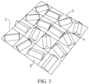
FIG. 3 is an arrangement diagram of partial grating portions of a decorative member according to an exemplary example of the present disclosure; -
FIG. 4 is an arrangement diagram of a grating portion according to an exemplary example of the present disclosure; -
FIG. 5 is a top view of partial grating portions of a decorative member according to an exemplary example of the present disclosure; -
FIG. 6 is a display effect diagram corresponding to arrangement angles of grating portions according to an exemplary example of the present disclosure; -
FIG. 7 is a cross-sectional view of grating portions according to an exemplary example of the present disclosure; -
FIG. 8 is a cross-sectional view of grating portions according to another exemplary example of the present disclosure; -
FIG. 9 is a cross-sectional view of grating portions according to another exemplary example of the present disclosure; -
FIG. 10 is an arrangement diagram of partial grating portions of a decorative member according to an exemplary example of the present disclosure. - Hereinafter, specific examples of the present disclosure will be described in detail with reference to the accompanying drawings. It should be understood that the specific example described herein is for illustration and explanation of the present disclosure only, and is not intended to limit the present disclosure.
- In the present disclosure, unless stated to the contrary, location words such as "inner and outer" are used with respect to the contour of the corresponding component itself. In addition, when the following description refers to the drawings, the same numbers in different drawings denote the same or similar elements unless otherwise indicated. The examples described in the following exemplary examples do not represent all examples consistent with the present disclosure. Rather, they are merely examples of devices and methods consistent with some aspects of the present disclosure as detailed in the appended claims.
- According to a first aspect of the present disclosure, a decorative member is provided, and the decorative member can be arranged on various products to improve aesthetics. For example, the decorative member can serve as a housing of an electronic device to present a desired light and shadow effect. Specifically, referring to
FIGS. 1 and2 , the decorative member includes asubstrate 1 and afirst texture layer 2 arranged on thesubstrate 1. Here, thesubstrate 1 can be made of the transparent material having a certain refractive index, for example, PC (Polycarbonate) sheet, PET (polyethylene terephthalate) sheet, or PC/PMMA (polymethyl methacrylate) composite sheet, and thesubstrate 1 can be a glass plate. Of course, thesubstrate 1 made of the non-transparent material can also be applied to the decorative member of the present disclosure without affecting the presentation of the effect of thefirst texture layer 2. - As shown in
FIGS. 1 and2 , thefirst texture layer 2 has a plurality of preset paths, and each of the preset paths has a plurality of gratingportions 3 arranged in sequence, in order to jointly present a hairline shape. A width of the hairline can be determined by the size and number of thegrating portion 3. For example, referring toFIG. 10 , the arrangement of thepartial grating portions 3 of a single hairline is roughly outlined by a thick black line inFIG. 10 , and the extension direction outlined by the thick black line can be understood as a preset path. InFIG. 10 , the area between two adjacent thick black lines represents the arrangement ofpartial grating portions 3 of the single hairline. As shown inFIG. 10 , a single hairline can be composed of a plurality of columns of a plurality of gratingportions 3 arranged on the preset path to form a thicker hairline effect. In other examples, only one column of gratingportions 3 can be arranged on the preset path to form a thinner hairline effect.FIG. 2 is a reduced view effect relative toFIG. 10 , but only partial texture layer is shown, without showing the entire hairline. InFIG. 2 , a plurality of successive pixel grids form a single hairline on the preset path. The gratingportions 3 inFIG. 2 form a plurality of hairlines on a plurality of preset paths, thus having an effect of hairline light and shadow. InFIG. 2 , the hairline with a wider pixel grid is formed by a plurality of columns of grating portions, and the hairline with a thinner pixel grid is formed by one column of grating portions. In conjunction withFIG. 6, FIG. 6 shows the light and shadow effects when thegrating portions 3 are observed at the same viewing angle, from left to right, the light and shadow reflected by thegrating portions 3 at the same viewing angle changes from dark to bright as the arrangement angles of thegrating portions 3 change. However, it should be noted here that when thesegrating portions 3 are viewed from other viewing angles, the corresponding light and shadow effects also change, rather than being limited to the effects shown inFIG. 6 , which illustrates only one viewing angle as an example. Among them, in the example of the present disclosure, referring toFIG. 10 , thegrating portions 3 on the two adjacent preset paths (that is, the two paths drawn by three thick black lines inFIG. 10 ) are arranged at different angles, and thegrating portions 3 on the path close to the right of the two paths drawn inFIG. 10 are rotated approximately by 45 ° with respect to thegrating portions 3 of the path on the left, which is merely illustrative and is not intended to limit the present disclosure. In other words, theadjacent grating portions 3 constituting the two adjacent hairlines are arranged at different angles, so that the two adjacent hairlines can present different light and shadow effects when viewed at the same viewing angle. - According to the above technical solution, a plurality of
grating portions 3 are arranged on a preset path to form a hairline effect, and the displayed effect of hairline light and shadow is realized to be more natural and not rigid. Moreover, thegrating portions 3 of adjacent hairlines are arranged at different angles, resulting in different light and shadow effects on two adjacent hairlines. While the boundary of the hairline is clear, it can also make the hairline flash alternately at different viewing angles, thus enhancing the flexibility and aesthetics of the decorative member. - In the example of the present disclosure, referring to
FIG. 3 , a surface of thesubstrate 1 is divided into a plurality ofunit cell areas 4 of the same size, and each of theunit cell areas 4 is filled with one of the grating portions 3.Here, theunit cell area 4 is constructed to facilitate the arrangement of thegrating portion 3 at the time of design, and the borders of theunit cell area 4 are not displayed in the product of the decorative member. Each of theunit cell areas 4 is arranged with agrating portion 3 through this arrangement, thus making the transition of light and shadow effects finally presented consistent and natural. - Further, referring to
FIG. 4 , theunit cell area 4 can be a square, and each of thegrating portions 3 can be centered at the center of the square, that is, the center of thegrating portion 3 can coincide with the center of the square. Thegrating portion 3 can extend to an inscribedcircle 41 of the square and connect to the inscribedcircle 41 of the square. In this way, it can ensure that the size of each of thegrating portions 3 is the same, thus making the displayed light and shadow effects more uniform. Among them, the inscribedcircle 41 here and the above-mentioned square are both constructed to facilitate the arrangement of thegrating portion 3 at the time of design, and the borders of both are not displayed in the product of the decorative member. - In other examples, each of the
grating portions 3 can also be arranged to be connected to an edge of theunit cell area 4 as shown inFIG. 3 , making the light and shadow effects coherent and smooth, thus having a naturally flowing effect. - According to one example of the present disclosure, a side length of the square can be set to 40-100 microns, for example, 50 microns. By defining the
unit cell area 4 to this size, the size of thegrating portion 3 in theunit cell area 4 can also ensure the naturally flowing effect of light and shadow on the premise of ensuring that it is technically easy to realize. - According to one example of the present disclosure, the tangent value of the included angle α (referring to
FIG. 3 ) can be between 1:30 and 4:1, and the included angle is between the reflecting surface of each of thegrating portions 3 and the surface of thesubstrate 1. For example, when thegrating portion 3 is a regular triangular prism shown inFIG. 3 , for example, when a height of the grating portion 3 (that is, the size of thegrating portion 3 in the direction perpendicular to the surface of the substrate 1) is 0.5 microns, the corresponding width of the grating portion 3 (that is, a width of the surface on which the triangular prism is bonded to the substrate 1) can be 30 microns. The range of tangent values can avoid presenting only flat effects due to excessive width, as well as avoiding non tilted reflecting surface effects due to insufficient width. - In one example, in conjunction with
FIGS. 7 and8 , a height H of each of thegrating portions 3 can be 0.5 microns to 20 microns, a width W of a cross section of each of thegrating portions 3 can be 10 microns to 50 microns, and the cross section is perpendicular to the corresponding preset path. A flowing hairline light and shadow effect with continuity can be achieved by thegrating portion 3 within the size range. Further, placing thegrating portion 3 of the size in the unit cell area which is a square having a side length of 50 microns is more conducive to obtaining better light and shadow effects. - In one example, the size of the
grating portion 3 can be determined according to the side length of the square, for example, a width of a cross section of thegrating portion 3 can be 20% to 60% of the side length of the square, for example 50% of the side length of the square, and the cross section is perpendicular to the corresponding preset path. For example, when the side length of the square is 50 microns, the width of thegrating portion 3 can be 10 to 30 microns, such as 20 microns. With this arrangement, clear and visible light and shadow effects can be obtained without being blurred due to too large size or being invisible due to too small size - In the example of the present disclosure, at least part of
grating portions 3 on each of the preset paths are arranged at different angles. By arranging thegrating portions 3 at different angles, thegrating portions 3 are changed with the effect of hairline flowing, so as to realize the effect of hairline flowing. In some examples, in order to realize the flowing light and shadow effect, part of adjacent grating portions along the preset path can be divided into a group, thus the preset path can be divided into a plurality of groups of gratings. The angles of gratingportions 3 in each group of gratings can be the same, and the angles of gratings of adjacent groups can be set to be different. In this way, thegrating portions 3 of the same angle within the same group are used to form hairline light and shadow, while the angle changes of the gratings between different groups can present light and shadows of different brightness to form a flowing hairline effect. For example, in some examples, the arrangement angle of the grating portion along a preset path of a hairline can be as follow: the arrangement angle of a group of gratingportions 3 at the starting end (here all angles are relative to the grating in the vertical direction) is 10°, and the arrangement angle of a group of gratingportions 3 at the end is 80°. The grating groups between the starting end and the end can be changed sequentially within the angle range, and in this arrangement, the effect of flowing hairline can be presented, that is, when viewed from a perspective, different light and dark effects are presented sequentially on a single hairline in a preset path (as shown inFIG. 1 ), thus obtaining a flowing hairline texture. When the arrangement angle of a hairline is between 10° and 80°, the arrangement angles of two hairlines can be 20° to 90° and 0° to 70°, respectively, and the two hairlines are adjacent to the hairline and on both sides of the hairline. Here, the arrangement angles of adjacent hairlines, and the arrangement angles of a single hairline are only described as examples, and in practical application, it can be adjusted according to the light and shadow effects to be displayed. - In an example of the present disclosure, the
grating portion 3 can include at least one of agrating portion 3 extending in a straight line and agrating portion 3 extending in a curve. Thegrating portion 3 extending in a straight line is, for example, thegrating portion 3 shown inFIGS. 3 to 5 , and thegrating portion 3 extending in a curve can be, for example, S-shaped extending, arc-shaped extending, or the like. In the example of the present disclosure, referring toFIGS. 7 to 9 , thegrating portion 3 can include at least one of a curvedgrating portion 31 having a reflecting surface configured as a curved surface and a planargrating portion 32 having a reflecting surface configured as a planar surface. For example, in a decorative member, thefirst texture layer 2 can include one of the aforementioned grating portions or a combination of various grating portions, and the types of gratingportions 3 on the same preset path can be the same or different. The curved reflecting surface can reflect from different angles, and the reflection intensity is slightly weaker than that of the planar reflecting surface. In practical application, the configuration of thegrating portion 3 of thefirst texture layer 2 can be set according to the desired light and shadow effects. - In some examples, as shown in
FIG. 9 , the curvedgrating portion 31 can include a grating portion having the cross section configured as an arc shape, and the cross section is perpendicular to the corresponding preset path. The arc surface has several tangent lines, which can reflect light from different angles, thus making the light and shadow effect softer. As shown inFIGS. 7 and8 , the planar gratingportion 32 can include a grating portion having the cross section configured as a triangular shape, and the cross section is perpendicular to the corresponding preset path. Because the reflecting surface of this grating portion is planar, the reflective intensity is greater, and the effect is brighter than that of the arc-shaped one. In the example of the present disclosure, the cross-sectional shape of thegrating portion 3 is not limited thereto, and will not be described in detail here. - In some examples, referring to
FIG. 7 , the planar gratingportion 32 can include a right angle grating portion having the cross section configured as a right angle triangle shape, and the cross section is perpendicular to the corresponding preset path. In one example of the present disclosure, thefirst texture layer 2 of the decorative member can be adjacently arranged with right angle grating portions on a plurality of adjacent preset paths, and the arrangement direction of the hypotenuse of the adjacent right angle grating portions is the same. A right angle side of the adjacent right angle grating portion is attached to thesubstrate 1, and the other right-angle side is adjacent to the hypotenuse of the adjacent right-angle grating portion. In this way, a plurality of right-angle grating portions are arranged adjacently to form an effect similar to that of a Fresnel lens, making the light and shadow effects presented transparent. In the example of the present disclosure, a combination of a plurality ofgrating portions 3 can be arranged according to the light and dark requirements of light and shadow, so that the light and shadow effect presented by the decorative member is natural and not rigid. - In one example, a surface of the
substrate 1 can be further arranged with a second texture layer having an effect different from that of thefirst texture layer 2. In some examples, thefirst texture layer 2 and the second texture layer can be respectively arranged in different areas of thesubstrate 1, for example, thesubstrate 1 is divided into two areas, thefirst texture layer 2 is arranged in one area, and the second texture layer is arranged in the other area, so that two kinds of light and shadow effects can be presented on the decorative member, which has peculiarity. Similarly, three or more areas can also be divided on thesubstrate 1, and each area is arranged with a different texture layer. In some examples, thefirst texture layer 2 and the second texture layer can be arranged on the entire surface of thesubstrate 1 and arranged in an intersecting manner, that is, a new light and shadow effect can be presented after thefirst texture layer 2 and the second texture layer arranged in an intersecting manner. In addition, it should be noted that in the example of the present disclosure, a combination of the above two methods can be adopted, that is, a part of thefirst texture layer 2 and the other texture layer can be arranged in the same area and arranged in an intersecting manner, and the other part of the first texture layer 2can be arranged independently of the texture layer of the other area, to make the decorative member present various light and shadow effects. - According to a second aspect of the example of the present disclosure, a housing of an electronic device is further provided. The housing of the electronic device includes the above-described decorative member and has all the beneficial effects of the above-described decorative member, which will not be described herein. In some examples, the housing of the electronic device can include a coating layer located on the surface of the decorative member in addition to the above-described decorative member, and the light and shadow effects of different colors can be presented in conjunction with the above-described decorative member having a hairline flowing effect. Of course, other functional layers can be added according to actual needs, or more decorative members can be superimposed.
- According to a third aspect of the present disclosure, an electronic device is further provided. The electronic device includes the housing of the electronic device described above to improve a visual effect. Among them, electronic devices include but are not limited to mobile phones, tablets, laptops, etc.
- Hereinafter, a method for preparing a product of the decorative member will be described in conjunction with the decorative member in the example of the present disclosure. The method for preparing the product of the decorative member includes the following steps: texture parameters are set by software, the preset texture is carved onto the mould by laser, and exposing, developing, drying, plasma cleaning and other operations are operated on the mould to obtain a texture mould; transferring and curing operations are operated on the texture mould to obtain the transfer mould; the texture is transferred to the
substrate 1 to transfer an optical texture layer on thesubstrate 1; a coating layer is deposited on the optical texture layer, and an ink layer is printed on one side of the coating layer; then, the film of the decorative member is attached to the glass by a process such as bonding to make a glass product having the decorative member. In other methods, it is possible to apply a preset texture to the glass product with homogeneous photoresist, and the preset texture structure can be obtained by photolithography, exposure and development; the glass with a texture layer is placed in an etching tank, and the texture is completely copied onto the glass through a reasonable etching time to form a decorative member in the present disclosure, wherein a glass plate is used as thesubstrate 1 here; then, optical coating can be performed on the side opposite the texture layer of the glass; and an ink layer is sprayed on one side of the coating layer, thereby obtaining a product having a decorative member. - Preferred examples of the present disclosure are described in detail above with reference to the accompanying drawings, but the present disclosure is not limited to the specific details in the above-described examples, and various simple modifications can be made to the technical solutions of the present disclosure within the scope of the technical concept of the present disclosure, and these simple modifications all fall within the scope of protection of the present disclosure.
- In addition, it should be noted that the specific technical features described in the above-described detailed examples can be combined in any suitable manner without contradiction, and in order to avoid unnecessary repetition, various possible combinations will not be described separately in the present disclosure.
- In addition, various different examples of the present disclosure can be arbitrarily combined, and the same should be regarded as the contents disclosed in the present disclosure as long as they do not violate the concept of the present disclosure.
Claims (13)
- A decorative member, comprising:a substrate (1); anda first texture layer (2), arranged on the substrate (1), the first texture layer (2) having a plurality of preset paths, each of the preset paths having a plurality of grating portions (3) arranged in sequence to jointly present a hairline shape, and the grating portions (3) on the two adjacent preset paths being arranged at different angles.
- The decorative member according to claim 1, wherein a surface of the substrate (1) is divided into a plurality of unit cell areas (4) of the same size, and each of the unit cell areas (4) is filled with one of the grating portions (3).
- The decorative member according to claim 2, wherein the unit cell area (4) is a square, each of the grating portions (3) is centered at the center of the square, and each of the grating portions (3) extends to an inscribed circle (41) of the square and connects to the inscribed circle (41) of the square, or each of the grating portions (3) extends to an edge of the square and connects to the edge of the square.
- The decorative member according to claim 2 or 3, wherein the unit cell area (4) is a square, and a side length of the square is 40 microns to 100 microns.
- The decorative member according to claim 3 or 4, wherein a width of a cross section of each of the grating portions (3) is 20% to 60% of the side length of the square, and the cross section is perpendicular to the corresponding preset path.
- The decorative member according to any one of claims 1 to 5, wherein the tangent value of the included angle is between 1:30 and 4: 1, and the included angle is between the reflecting surface of each of the grating portions (3) and the surface of the substrate (1).
- The decorative member according to any one of claims 1 to 6, wherein a height of each of the grating portion (3) is 0.5 microns to 20 microns, a width of a cross section of each of the grating portions (3) is 10 microns to 50 microns, and the cross section is perpendicular to the corresponding preset path.
- The decorative member according to any one of claims 1 to 7, wherein at least part of grating portions (3) on each of the preset paths are arranged at different angles.
- The decorative member according to any one of claims 1 to 8, wherein the grating portions (3) comprise at least one of a grating portion extending in a straight line and a grating portion extending in a curve.
- The decorative member according to any one of claims 1 to 9, wherein the grating portions (3) comprise at least one of a curved grating portion (31) having a reflecting surface configured as a curved surface and a planar grating portion (32) having a reflecting surface configured as a planar surface.
- The decorative member according to any one of claims 1 to 10, wherein a surface of the substrate (1) is further arranged with a second texture layer having an effect different from the first texture layer (2),
the first texture layer (2) and the second texture layer are respectively arranged at different areas of the substrate (1), or the first texture layer (2) and the second texture layer are both arranged on the entire surface of the substrate (1) and arranged in an intersecting manner. - A housing of an electronic device, comprising a decorative member according to any one of claims 1 to 11.
- An electronic device, comprising a housing of the electronic device according to claim 12.
Applications Claiming Priority (2)
| Application Number | Priority Date | Filing Date | Title |
|---|---|---|---|
| CN202221961700.3U CN217787424U (en) | 2022-07-26 | 2022-07-26 | Decorative parts, housings for electronic equipment, and electronic equipment |
| PCT/CN2023/090697 WO2024021715A1 (en) | 2022-07-26 | 2023-04-25 | Decorative member, housing of electronic device, and electronic device |
Publications (2)
| Publication Number | Publication Date |
|---|---|
| EP4561276A1 true EP4561276A1 (en) | 2025-05-28 |
| EP4561276A4 EP4561276A4 (en) | 2025-10-29 |
Family
ID=83942656
Family Applications (1)
| Application Number | Title | Priority Date | Filing Date |
|---|---|---|---|
| EP23844930.0A Pending EP4561276A4 (en) | 2022-07-26 | 2023-04-25 | DECORATIVE ELEMENT, HOUSING OF AN ELECTRONIC DEVICE AND ELECTRONIC DEVICE |
Country Status (6)
| Country | Link |
|---|---|
| US (1) | US20250155617A1 (en) |
| EP (1) | EP4561276A4 (en) |
| JP (1) | JP2025530020A (en) |
| KR (1) | KR20250029181A (en) |
| CN (1) | CN217787424U (en) |
| WO (1) | WO2024021715A1 (en) |
Families Citing this family (5)
| Publication number | Priority date | Publication date | Assignee | Title |
|---|---|---|---|---|
| CN217787424U (en) * | 2022-07-26 | 2022-11-11 | 比亚迪股份有限公司 | Decorative parts, housings for electronic equipment, and electronic equipment |
| CN118219699A (en) * | 2022-12-20 | 2024-06-21 | 比亚迪股份有限公司 | Appearance decorative part, method for manufacturing appearance decorative part, and electronic device |
| CN115938203B (en) * | 2022-12-29 | 2025-07-25 | 珠海市瑞明科技有限公司 | Methods for simulating hair texture |
| CN221829180U (en) * | 2023-02-24 | 2024-10-11 | 比亚迪股份有限公司 | Decorative parts, housings and electronic equipment |
| CN118269507A (en) * | 2023-05-19 | 2024-07-02 | 比亚迪股份有限公司 | Decorative piece, method for making decorative piece, and electronic device |
Family Cites Families (7)
| Publication number | Priority date | Publication date | Assignee | Title |
|---|---|---|---|---|
| JP4305067B2 (en) * | 2003-06-18 | 2009-07-29 | 凸版印刷株式会社 | Optical sheet comprising a blazed diffraction grating |
| US20100068424A1 (en) * | 2008-09-16 | 2010-03-18 | Mitac Technology Corp. | Decoration board and manufacture method thereof |
| JP6520359B2 (en) * | 2015-04-30 | 2019-05-29 | 凸版印刷株式会社 | Display body, article, original plate, and method of producing original plate |
| CN110996580B (en) * | 2019-12-06 | 2022-05-03 | 维沃移动通信有限公司 | Shell, electronic equipment and preparation method of shell |
| CN113189688A (en) * | 2021-04-27 | 2021-07-30 | 维沃移动通信有限公司 | Cover plate and electronic equipment |
| CN113194663A (en) * | 2021-04-27 | 2021-07-30 | 维沃移动通信有限公司 | Cover plate, electronic equipment and preparation method of cover plate |
| CN217787424U (en) * | 2022-07-26 | 2022-11-11 | 比亚迪股份有限公司 | Decorative parts, housings for electronic equipment, and electronic equipment |
-
2022
- 2022-07-26 CN CN202221961700.3U patent/CN217787424U/en active Active
-
2023
- 2023-04-25 WO PCT/CN2023/090697 patent/WO2024021715A1/en not_active Ceased
- 2023-04-25 EP EP23844930.0A patent/EP4561276A4/en active Pending
- 2023-04-25 JP JP2025504339A patent/JP2025530020A/en active Pending
- 2023-04-25 KR KR1020257002697A patent/KR20250029181A/en active Pending
-
2025
- 2025-01-16 US US19/024,613 patent/US20250155617A1/en active Pending
Also Published As
| Publication number | Publication date |
|---|---|
| EP4561276A4 (en) | 2025-10-29 |
| JP2025530020A (en) | 2025-09-10 |
| CN217787424U (en) | 2022-11-11 |
| KR20250029181A (en) | 2025-03-04 |
| US20250155617A1 (en) | 2025-05-15 |
| WO2024021715A1 (en) | 2024-02-01 |
Similar Documents
| Publication | Publication Date | Title |
|---|---|---|
| US20250155617A1 (en) | Decorative Member, Housing of Electronic Device, and Electronic Device | |
| TWI812690B (en) | optical device | |
| JP3900975B2 (en) | REFLECTOR, REFLECTIVE DISPLAY DEVICE, ELECTRONIC DEVICE, LIGHT REFLECTION METHOD, AND IMAGE DISPLAY METHOD | |
| CN111599835B (en) | Display panel and preparation method thereof | |
| CN101749598A (en) | Illuminating device and display device having the same | |
| EP4303928A1 (en) | Light-emitting module and method for manufacturing the same, display panel, and electronic device | |
| US20230236346A1 (en) | Transparent plate and fabricating method therefor, housing, and mobile terminal | |
| CN110239085A (en) | Three-dimensional printing device | |
| CN207571329U (en) | Optical thin film and the shell with the optical thin film | |
| CN109041477B (en) | Decorative film | |
| CN207181727U (en) | Optical thin film and the shell with the optical thin film | |
| WO2024051355A1 (en) | Decorative substrate, preparation method therefor and application thereof | |
| CN219181794U (en) | Decoration, casing of electronic equipment and electronic equipment | |
| WO2024174546A1 (en) | Decorative member, housing, and electronic device | |
| CN207181730U (en) | Optical thin film and the shell with the optical thin film | |
| EP4506184A1 (en) | Texture structure, cover plate, mobile terminal, and preparation method for cover plate | |
| CN109471207A (en) | Optical film and preparation method thereof, and casing with the optical film | |
| CN106772709B (en) | A kind of preparation method of display device and optical thin film therein | |
| US20250012955A1 (en) | Decorative substrate and manufacturing method therefor, cover plate and electronic device | |
| CN118544725A (en) | Decorative parts, housings and electronic equipment | |
| US12635314B2 (en) | Light-emitting module emitting color light and method for manufacturing the same, display panel, and electronic device | |
| CN207764397U (en) | Optical thin film and its shell with the optical thin film | |
| CN207181729U (en) | Optical thin film and the shell with the optical thin film | |
| CN207181728U (en) | Optical thin film and the shell with the optical thin film | |
| WO2024032086A1 (en) | Decorative plate and preparation method therefor, and electronic device |
Legal Events
| Date | Code | Title | Description |
|---|---|---|---|
| STAA | Information on the status of an ep patent application or granted ep patent |
Free format text: STATUS: THE INTERNATIONAL PUBLICATION HAS BEEN MADE |
|
| PUAI | Public reference made under article 153(3) epc to a published international application that has entered the european phase |
Free format text: ORIGINAL CODE: 0009012 |
|
| STAA | Information on the status of an ep patent application or granted ep patent |
Free format text: STATUS: REQUEST FOR EXAMINATION WAS MADE |
|
| 17P | Request for examination filed |
Effective date: 20250220 |
|
| AK | Designated contracting states |
Kind code of ref document: A1 Designated state(s): AL AT BE BG CH CY CZ DE DK EE ES FI FR GB GR HR HU IE IS IT LI LT LU LV MC ME MK MT NL NO PL PT RO RS SE SI SK SM TR |
|
| A4 | Supplementary search report drawn up and despatched |
Effective date: 20250930 |
|
| RIC1 | Information provided on ipc code assigned before grant |
Ipc: H05K 5/02 20060101AFI20250924BHEP Ipc: G02B 5/18 20060101ALI20250924BHEP Ipc: B44F 1/02 20060101ALI20250924BHEP Ipc: B44F 1/14 20060101ALI20250924BHEP |
|
| DAV | Request for validation of the european patent (deleted) | ||
| DAX | Request for extension of the european patent (deleted) |