EP4561265A1 - Led drive module - Google Patents
Led drive module Download PDFInfo
- Publication number
- EP4561265A1 EP4561265A1 EP23843432.8A EP23843432A EP4561265A1 EP 4561265 A1 EP4561265 A1 EP 4561265A1 EP 23843432 A EP23843432 A EP 23843432A EP 4561265 A1 EP4561265 A1 EP 4561265A1
- Authority
- EP
- European Patent Office
- Prior art keywords
- sensing unit
- fault
- ultraviolet led
- switch
- led
- Prior art date
- Legal status (The legal status is an assumption and is not a legal conclusion. Google has not performed a legal analysis and makes no representation as to the accuracy of the status listed.)
- Pending
Links
Images




Classifications
-
- G—PHYSICS
- G01—MEASURING; TESTING
- G01R—MEASURING ELECTRIC VARIABLES; MEASURING MAGNETIC VARIABLES
- G01R31/00—Arrangements for testing electric properties; Arrangements for locating electric faults; Arrangements for electrical testing characterised by what is being tested not provided for elsewhere
- G01R31/50—Testing of electric apparatus, lines, cables or components for short-circuits, continuity, leakage current or incorrect line connections
- G01R31/52—Testing for short-circuits, leakage current or ground faults
-
- H—ELECTRICITY
- H05—ELECTRIC TECHNIQUES NOT OTHERWISE PROVIDED FOR
- H05B—ELECTRIC HEATING; ELECTRIC LIGHT SOURCES NOT OTHERWISE PROVIDED FOR; CIRCUIT ARRANGEMENTS FOR ELECTRIC LIGHT SOURCES, IN GENERAL
- H05B45/00—Circuit arrangements for operating light-emitting diodes [LED]
- H05B45/50—Circuit arrangements for operating light-emitting diodes [LED] responsive to malfunctions or undesirable behaviour of LEDs; responsive to LED life; Protective circuits
- H05B45/56—Circuit arrangements for operating light-emitting diodes [LED] responsive to malfunctions or undesirable behaviour of LEDs; responsive to LED life; Protective circuits involving measures to prevent abnormal temperature of the LEDs
-
- G—PHYSICS
- G01—MEASURING; TESTING
- G01R—MEASURING ELECTRIC VARIABLES; MEASURING MAGNETIC VARIABLES
- G01R31/00—Arrangements for testing electric properties; Arrangements for locating electric faults; Arrangements for electrical testing characterised by what is being tested not provided for elsewhere
- G01R31/44—Testing lamps
-
- G—PHYSICS
- G01—MEASURING; TESTING
- G01R—MEASURING ELECTRIC VARIABLES; MEASURING MAGNETIC VARIABLES
- G01R31/00—Arrangements for testing electric properties; Arrangements for locating electric faults; Arrangements for electrical testing characterised by what is being tested not provided for elsewhere
- G01R31/50—Testing of electric apparatus, lines, cables or components for short-circuits, continuity, leakage current or incorrect line connections
- G01R31/54—Testing for continuity
-
- H—ELECTRICITY
- H05—ELECTRIC TECHNIQUES NOT OTHERWISE PROVIDED FOR
- H05B—ELECTRIC HEATING; ELECTRIC LIGHT SOURCES NOT OTHERWISE PROVIDED FOR; CIRCUIT ARRANGEMENTS FOR ELECTRIC LIGHT SOURCES, IN GENERAL
- H05B45/00—Circuit arrangements for operating light-emitting diodes [LED]
- H05B45/30—Driver circuits
- H05B45/345—Current stabilisation; Maintaining constant current
-
- H—ELECTRICITY
- H05—ELECTRIC TECHNIQUES NOT OTHERWISE PROVIDED FOR
- H05B—ELECTRIC HEATING; ELECTRIC LIGHT SOURCES NOT OTHERWISE PROVIDED FOR; CIRCUIT ARRANGEMENTS FOR ELECTRIC LIGHT SOURCES, IN GENERAL
- H05B45/00—Circuit arrangements for operating light-emitting diodes [LED]
- H05B45/50—Circuit arrangements for operating light-emitting diodes [LED] responsive to malfunctions or undesirable behaviour of LEDs; responsive to LED life; Protective circuits
-
- H—ELECTRICITY
- H05—ELECTRIC TECHNIQUES NOT OTHERWISE PROVIDED FOR
- H05B—ELECTRIC HEATING; ELECTRIC LIGHT SOURCES NOT OTHERWISE PROVIDED FOR; CIRCUIT ARRANGEMENTS FOR ELECTRIC LIGHT SOURCES, IN GENERAL
- H05B47/00—Circuit arrangements for operating light sources in general, i.e. where the type of light source is not relevant
- H05B47/20—Responsive to malfunctions or to light source life; for protection
- H05B47/28—Circuit arrangements for protecting against abnormal temperature
Definitions
- the present invention relates to an LED driving module.
- LEDs light emitting diodes
- LEDs can be classified into infrared LEDs configured to emit infrared light, visible LEDs configured to emit visible light, and ultraviolet LEDs configured to emit ultraviolet light.
- Ultraviolet (UV) LEDs have been applied to a variety of products after it was found that UV light can kill DNA or RNA bacteria. In recent years, compact products employing a single light emitting diode have been developed in consideration of storage and portability.
- such products may be provided with a separate light emitting diode and a driving module for driving the light emitting diode.
- an LED driving module provided with a single ultraviolet LED and including a fault sensing unit.
- the fault sensing unit may be configured to sense a fault of the ultraviolet LED.
- the fault sensing unit may include a connection sensing unit configured to sense a connection state of the ultraviolet LED.
- the connection sensing unit may output a fault signal through a fault signal output terminal when a fault occurs due to short or opening of the ultraviolet LED.
- connection sensing unit may include a connection sensing switch turned on and turned off corresponding to a voltage of a node connected to the ultraviolet LED.
- the node connected to the ultraviolet LED may be connected to an anode terminal of the ultraviolet LED.
- the connection sensing switch may include a first end, a second end, and a third end through which signals are input or output.
- a voltage corresponding to the voltage of the node may be applied to the first end to turn on and turn off the connection sensing switch.
- the second end may be connected to the fault signal output terminal.
- the third end may be connected to ground.
- the fault signal output terminal may include a first fault signal output terminal and a second fault signal output terminal.
- the first fault signal output terminal may output a first fault signal when the ultraviolet LED is in a short state.
- the second fault signal output terminal may output a second fault signal when the ultraviolet LED is in an open state.
- the first fault signal output terminal may be connected to a node connecting the second end of the connection sensing switch and one end of a resistor.
- the second fault signal output terminal may be connected to a node connecting two resistors in series between the anode terminal of the ultraviolet LED and ground.
- the resistor connected to the second end of the connection sensing switch may be connected at the other end thereof to ground.
- the fault sensing unit may further include a heat sensing unit configured to sense a heating state of the ultraviolet LED.
- the heat sensing unit may include: a thermal resistor whose resistance varies depending on ambient temperature; and a heat sensing switch connected to the thermal resistor.
- the thermal resistor may be connected to the anode terminal of the ultraviolet LED.
- the heat sensing switch may be turned on and turned off in response to a voltage varying according to resistance of the thermal resistor.
- the heat sensing switch may include a first end, a second end, and a third end through which signals are input or output.
- the first end may receive a voltage varying according to resistance of the thermal resistor.
- the second end may be connected to the fault signal output terminal.
- the third end may be connected to ground.
- the fault signal output terminal may include a first fault signal output terminal, a second fault signal output terminal, and a third fault signal output terminal.
- the first fault signal output terminal may output a first fault signal when the ultraviolet LED is in a short state.
- the second fault signal output terminal may output a second fault signal when the ultraviolet LED is in an open state.
- the third fault signal output terminal may output a third fault signal when the ultraviolet LED is in an overheating state.
- the first fault signal output terminal may be connected to a node connecting the second end of the connection sensing switch to one end of a resistor.
- the second fault signal output terminal may be connected to a node connecting two resistors in series between the anode terminal of the ultraviolet LED and ground.
- the third fault signal output terminal may be connected to a node connecting the second end of the heat sensing switch to one end of a resistor.
- Each of the resistor connected to the second end of the connection sensing switch and the resistor connected to the second end of the heat sensing unit may be connected at the other end thereof to ground.
- connection sensing unit may include an opening sensing unit configured to sense an open state of the ultraviolet LED and a short sensing unit configured to sense a short state of the ultraviolet LED.
- Each of the opening sensing unit and the short sensing unit may include an amplifier configured to compare a reference voltage with an input voltage and at least a switch turned on and off by an output signal of the amplifier.
- the opening sensing unit may include an opening sensing switch.
- the opening sensing switch may include a first end, a second end, and a third end through which signals are input or output.
- the first end may receive a voltage for turning on and turning off the switch in response to a signal output from the amplifier of the opening sensing unit.
- the second end may be connected to the fault signal output terminal.
- the third end may allow a current input through the first end to pass therethrough when the opening sensing switch is in a turn-on state.
- the short sensing unit may include a short sensing switch.
- the short sensing switch may include a first end, a second end, and a third end through which signals are input or output.
- the first end may receive a voltage for turning on and turning off the switch in response to a signal output from an amplifier of the short sensing unit.
- the second end may be connected to the fault signal output terminal.
- the third end may allow a current input through the first end to pass therethrough when the short sensing switch is in a turn-on state.
- the fault signal output terminal may output a normal signal when the ultraviolet LED is in a normal state.
- the fault signal may be a lower voltage than the normal signal.
- the LED driving module may further include a Zener diode connected at one end thereof to the fault signal output terminal and at the other end thereof to ground.
- the normal signal may be a Zener voltage.
- the LED driving module may further include a current sensing unit and a control signal generator.
- the current sensing unit may be configured to sense a current supplied to the ultraviolet LED.
- the control signal generator may be configured to generate and output a signal to control a switch according to a current value sensed by the current sensing unit.
- the control signal generator may output a short signal to the switch to turn on the switch and an open signal to turn off the switch.
- the connection sensing unit may sense the short signal and the open signal output from the control signal generator to the switch.
- the fault sensing unit may generate and output a fault signal when the short signal or the open signal sensed by the connection sensing unit is sensed for a preset period of time or more.
- the fault sensing unit may further include a heat sensing unit configured to sense a temperature of the ultraviolet LED or an ambient temperature of the ultraviolet LED.
- the fault sensing unit may generate and output a fault signal when the temperature sensed by the heat sensing unit is greater than or equal to a preset temperature.
- the LED driving module may further include a constant current unit configured to supply a constant current to the ultraviolet LED.
- an LED driving module configured to sense a faulty state of a UV LED can determine whether a fault occurs in the UV LED.
- the LED driving module outputs a signal according to the type of failure that has occurred in the UV LED, whereby a faulty state of the UV LED can be accurately identified.
- the LED driving module may be suitable for small products by realizing a simple circuit configured to sense a fault of the LED to minimize increase in size thereof.
- LED driving modules are applied to small products employing ultraviolet LEDs.
- the LED driving modules according to the embodiments of the present invention may sense a fault of an ultraviolet LED, and generate and output a fault signal. More specifically, the LED driving modules may output a normal signal indicating a normal state and a fault signal indicating a faulty state depending on the state of the ultraviolet LED.
- a fault sensing unit configured to sense a fault of the ultraviolet LED.
- FIG. 1 to FIG. 3 are views of an LED driving module according to a first embodiment of the present invention.
- FIG. 1 is a schematic block diagram of an LED driving module according to a first embodiment of the present invention.
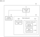
- FIG. 2 is a schematic block diagram of the LED driving module according to the first embodiment of the present invention.
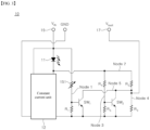
- FIG. 3 is a circuit diagram of a fault sensing unit of the LED driving module according to the first embodiment of the present invention.
- the LED driving module 10 may include an ultraviolet LED 11, a constant current unit 12, and a fault sensing unit 13.
- the constant current unit 12 may be disposed at the rear end of the ultraviolet LED 11. That is, in the LED driving module 10 according to the first embodiment, the constant current unit 12 may be connected to a cathode terminal of the ultraviolet LED 11 to control a current flowing in the ultraviolet LED 11.
- the LED driving module 10 is a module to be applied to small products and may include one ultraviolet LED 11.
- the constant current unit 12 enables a constant current to flow in the ultraviolet LED 11 when the ultraviolet LED 11 is turned on.
- the constant current unit 12 may control the current flowing in the ultraviolet LED 11 to be constant such that the intensity of UV light emitted from the ultraviolet LED 11 is constant.
- the constant current unit 12 may be realized as a circuit of various structures using resistors, transistors, diodes, Zener diodes, and the like.
- the constant current unit 12 according to this embodiment may include any of constant current circuits known to those skilled in the art.
- the fault sensing unit 13 may be configured to sense a fault that has occurred in the ultraviolet LED 11.
- the fault sensing unit 13 may include a connection sensing unit 110 and a heat sensing unit 150.
- connection sensing unit 110 may be configured to sense an abnormality in a connection state of the ultraviolet LED 11. That is, the connection sensing unit 110 may be configured to sense failure of the connection state, such as opening and short circuit of the ultraviolet LED 11.
- the heat sensing unit 150 may be configured to sense a heating state of the ultraviolet LED 11 by detecting an ambient temperature.
- the ultraviolet LED 11 may generate heat due to various causes, such as contact between a semiconductor and a metal, lattice vibration (phonon), heat conversion of light reabsorbed by total reflection from the surface, leakage current, and the like.
- the ultraviolet LED 11 emits heat
- the ambient temperature of the ultraviolet LED 11 increases.
- the ambient temperature of other devices including the LED driving module 10 also increases. That is, the heat sensing unit 150 can detect a fault of the ultraviolet LED 11 by sensing a change in ambient temperature.
- the fault sensing unit 13 may sense a heating state and the connection state between the anode terminal and the cathode terminal of the ultraviolet LED 11 and may output a fault signal indicating an abnormal state when the abnormal state is sensed. Further, the fault sensing unit 13 may output a normal signal indicating a normal state of the ultraviolet LED 11 when no fault of the ultraviolet LED 11 is sensed.
- the LED driving module 10 may include an input terminal 15 that receives signals from the outside and a fault signal output terminal 17 that outputs signals to the outside.
- a driving voltage is supplied to the ultraviolet LED 11 through the input terminal 15.
- a fault signal indicating a fault state of the ultraviolet LED 11 may be output through the fault signal output terminal 17.
- a normal signal indicating a normal state of the ultraviolet LED 11 may be output through the fault signal output terminal 17.
- the constant current unit 12 may be disposed at the rear end of the ultraviolet LED 11. That is, the constant current unit 12 may be connected to the cathode terminal of the ultraviolet LED 11.
- the fault sensing unit 13 may also be disposed at the rear end of the ultraviolet LED 11 and may be connected to the cathode terminal of the ultraviolet LED 11.
- FIG. 3 is a circuit diagram of the LED driving module 10.
- the circuit constituting the fault sensing unit 13 of the LED driving module 10 may include switches each provided with a plurality of terminals through which signals are input or output.
- the switches may be NPN-type bipolar transistors.
- each of the switches may include three terminals through which signals are input or output.
- the switch may include a first end as a base terminal, a second end as a collector terminal, and a third end as an emitter terminal.
- the signals input to the switch may be a voltage and a current.
- the heat sensing unit 150 may include a thermal resistor 151, a first switch SW 1 , and a first resistor R 1 .
- the thermal resistor 151 refers to a device whose resistance value changes with change in temperature.
- the thermal resistor 151 may be a negative temperature coefficient (NTC) thermistor that has characteristics of a negative resistance temperature coefficient, in which the resistance decreases when the temperature increases. That is, according to this embodiment, when the temperature around the thermal resistor 151 is higher than or equal to a certain temperature, the resistance value of the thermal resistor 151 decreases.
- NTC negative temperature coefficient
- the thermal resistor 151 may be connected at a first end thereof to the anode terminal of the ultraviolet LED 11 and connected at a second end thereof to a first end of the first resistor R 1 .
- the first switch SW 1 may be connected at a first end thereof to a first node (Node 1) to which the second end of the thermal resistor 151 and the first end of the first resistor R 1 are connected.
- the first switch SW 1 may be connected at a second end thereof to a second end of the second switch SW 2 .
- the second end of the first switch SW 1 may be connected to the fault signal output terminal 17 that is an output terminal of the fault sensing unit 13.
- a second end of the first resistor R 1 and a third end of the first switch SW 1 may be connected to ground.
- connection sensing unit 110 may include a second switch SW 2 , a second resistor R 2 , a third resistor R 3 , and a fifth resistor R 5 .
- the second resistor R 2 may be connected at a first end thereof to the cathode terminal of the ultraviolet LED 11 and connected at a second end thereof to a first end of the third resistor R 3 . That is, the second resistor R 2 and the third resistor R 3 may be connected in series.
- a fourth resistor R 4 may be connected at a first end thereof to the cathode terminal of the ultraviolet LED 11. That is, the first end of the fourth resistor R 4 may be connected to a second node (Node 2) to which the cathode terminal of the ultraviolet LED 11 and the first end of the second resistor R 2 are connected. In addition, the fourth resistor R 4 may be connected at a second end thereof to a first end of the fifth resistor R 5 . That is, the fourth resistor R 4 and the fifth resistor R 5 may be connected in series. In addition, the fourth resistor R 4 and the fifth resistor R 5 may be connected in parallel to the second resistor R 2 and the third resistor R 3 .
- the second switch SW 2 may be connected at a first end thereof to a third node (Node 3), to which the second end of the fourth resistor R 4 and the first end of the fifth resistor R 5 are connected.
- the second switch SW 2 may be connected at a second end thereof to a fourth node (Node 4) to which the second resistor R 2 and the third resistor R 3 are connected, and to a fifth node (Node 5) to which the second end of the first switch SW 1 is connected. That is, the second end of the second switch SW 2 may be connected to the fault signal output terminal 17 of the fault sensing unit 13.
- a second end of the fifth resistor R 5 , a third end of the second switch SW 2 , and a second end of the third resistor R 3 may be connected to ground.
- the heat sensing unit 150 and the connection sensing unit 110 may be connected to the fault signal output terminal 17. That is, the fault sensing unit 13 may be formed such that the heat sensing unit 150 and the connection sensing unit 110 share the same fault signal output terminal 17. Thus, the fault sensing unit 13 may output a fault signal when any of a fault caused by heat generation of the ultraviolet LED 11 and a fault caused by the connection state is sensed.
- the fault sensing unit 13 may allow a voltage at the fault signal output terminal 17 to become 0 V when the ultraviolet LED 11 fails due to heat generation or the connection state. That is, the fault sensing unit 13 of the LED driving module 10 according to this embodiment may be designed such that 0 V output from the fault signal output terminal 17 becomes a fault signal indicating a fault of the ultraviolet LED 11.
- the ambient temperature of the ultraviolet LED 11 increases. Since the LED driving module 10 according to this embodiment is a compact device, the ambient temperature of the thermal resistor 151 also increases due to heat generation of the ultraviolet LED 11. Accordingly, the heat sensing unit 150 according to this embodiment can sense the degree of heat generation from the ultraviolet LED 11 based on the ambient temperature sensed by the thermal resistor 151.
- the thermal resistor 151 of the heat sensing unit 150 may decrease in resistance when the ambient temperature increases.
- a voltage distributed by the thermal resistor 151 and the first resistor R 1 may be applied to the first end of the first switch SW 1 .
- the resistance value of the thermal resistor 151 decreases due to increase in ambient temperature, the voltage applied to the first end of the first switch SW 1 also increases.
- the first switch SW 1 When a voltage higher than a preset operation voltage of the first switch SW 1 is applied to the first end of the first switch SW 1 , the first switch SW 1 may be turned on.
- the operation voltage refers to a reference voltage at which the first switch SW 1 is turned on or turned off.
- the operation voltage may be a reference for distinguishing between normal heating and abnormal overheating of the ultraviolet LED 11.
- the operation voltage of the switches may be set as a threshold voltage.
- the first switch SW 1 of the heat sensing unit 150 is a heat sensing switch that operates according to the heating temperature of the ultraviolet LED 11.
- the heat sensing unit 150 may generate a fault signal indicating a fault of the ultraviolet LED 11 by allowing the first switch SW1 to be turned on when the ambient temperature is increased above a certain temperature by the ultraviolet LED 11.
- the certain temperature refers to a reference temperature with respect to an overheating state that occurs when the ultraviolet LED 11 is abnormal.
- connection sensing unit 110 may sense a fault caused by the connection state of the ultraviolet LED 11. That is, the connection sensing unit 110 may sense short circuit and opening of the ultraviolet LED 11.
- connection sensing unit 110 may allow the voltage at the fault signal output terminal 17 to become 0 V when the ultraviolet LED 11 is in a short state.
- the second switch SW 2 is connected at the first end thereof to the third node (Node 3). Thus, the second switch SW 2 may be turned on or off depending on the voltage at the third node (Node 3).
- the second switch SW 2 may be in a turn-off state when the voltage at the first end thereof is less than a preset operation voltage.
- the second switch SW 2 may be turned on when the voltage at the first end thereof is greater than or equal to the preset operation voltage.
- the preset operation voltage may become a reference for defining a short state of the ultraviolet LED 11.
- the operation voltage may be a threshold voltage of the second switch SW 2 .
- the second switch SW 2 is a connection sensing switch that operates according to the connection state of the ultraviolet LED 11.
- the second node When the ultraviolet LED 11 is in a normal state, the second node (Node 2) has a voltage corresponding to a voltage drop from a driving voltage to the operation voltage of the ultraviolet LED 11. When the ultraviolet LED 11 is in a normal state, a voltage smaller than the preset operation voltage may be applied to the first end of the second switch SW 2 . Here, the second switch SW 2 may be kept in a turn-off state.
- the fault signal output terminal 17 may output a voltage distributed by the second resistor R 2 and the third resistor R 3 .
- the voltage at the fault signal output terminal 17 may be calculated according to Equation 1.
- V fault V IN ⁇ V LED ⁇ R 3 / R 2 + R 3
- V fault denotes a voltage output from the fault signal output terminal 17 and corresponds to a fault signal.
- V IN denotes a driving voltage supplied through the input terminal 15
- V LED denotes the operation voltage of the ultraviolet LED
- R 2 denotes the second resistor
- R 3 denotes the third resistor.
- the voltage at the second node 2 may be the same as the driving voltage. That is, when the ultraviolet LED 11 is in a short state, a higher voltage is applied to the second node 2 than when the ultraviolet LED 11 is in a normal state. Then, the second switch SW 2 may be turned on by a voltage at the first end thereof, which is higher than or equal to the operation voltage.
- the voltage at the second node 2 is 0 V. Accordingly, the voltage at the fault signal output terminal 17 may become 0 V.
- connection sensing unit 110 may output 0 V corresponding to a fault signal to the fault signal output terminal 17.
- the LED driving module 10 may output a normal signal corresponding to a voltage of (V IN - V LED )(R 1 /(R 1 +R 2 )) to the fault signal output terminal 17 when the ultraviolet LED 11 is normal both in heat generation and connection thereof. Further, the LED driving module 10 may output a fault signal corresponding to a voltage of 0 V to the fault signal output terminal 17 when the ultraviolet LED 11 is in any one state among a short state, an open state, and an abnormal heating state.
- the fault sensing unit 13 of the LED driving module 10 allows 0 V to be output from the fault signal output terminal 17 when a fault occurs in the ultraviolet LED 11, but is not limited thereto.
- the fault sensing unit 13 may include a circuit adapted to output an arbitrary voltage other than 0 V as a fault signal. That is, the fault signal of the fault sensing unit 13 may be a preset voltage output when a fault occurs in the ultraviolet LED 11.
- the fault sensing unit 13 may output a normal signal distinguished from the fault signal when the ultraviolet LED 11 is in a normal state. That is, the fault sensing unit 13 of the LED driving module 10 according to this embodiment may be configured with a circuit capable of outputting signals that can distinguish between when the ultraviolet LED 11 is in a normal state and when the ultraviolet LED 11 is in a faulty state.
- the LED driving module 10 includes the fault sensing unit 13 that outputs a signal capable of distinguishing between when the ultraviolet LED 11 is in a normal state and when the ultraviolet LED 11 is in a faulty state.
- the fault sensing unit 13 that outputs a signal capable of distinguishing between when the ultraviolet LED 11 is in a normal state and when the ultraviolet LED 11 is in a faulty state.
- the thermal resistor 151 is described as an NTC by way of example.
- the heat sensing unit 150 according to this embodiment is not limited thereto.
- the thermal resistor 151 of the heat sensing unit 150 may be a positive temperature coefficient (PTC) thermistor having characteristics of a constant resistance temperature coefficient such that the resistance value increases as the temperature increases.
- the first switch SW1 of the heat sensing unit 150 may be set to be turned on at a preset operation voltage or less.
- the switches in the fault sensing unit 13 are described as NPN type bipolar transistors by way of example.
- the type of switches applied to this embodiment is not limited to the NPN type bipolar transistor.
- the switches of the fault sensing unit 13 may be configured with diodes or MOSFETs.
- the switches may be transistors that are turned on at a lower voltage than the operation voltage or threshold voltage.
- the switches may be any devices that are turned on or off in response to an input signal.
- the fault sensing unit 13 may be implemented in various ways so long as the fault sensing unit is capable of sensing a normal state and a faulty state of the ultraviolet LED 11 and outputting a signal capable of distinguishing the normal state and the faulty state.
- the LED driving module 10 according to this embodiment may be applied to a small product employing a single UV LED 11. As the demand for small products increases, the LED driving module 10 according to this embodiment also maintains the size for small products. Furthermore, the LED driving module 10 according to this embodiment includes the fault sensing unit 13 configured to sense an abnormality of the ultraviolet LED 11 and to generate a signal corresponding to the abnormality.
- the LED driving module 10 according to this embodiment is realized to sense a fault of the ultraviolet LED 11 through a simple circuit. Accordingly, the LED driving module 10 according to this embodiment can sense a fault of the ultraviolet LED 11 and output a signal indicating the fault while maintaining the size of a conventional LED driving module.
- FIG. 4 and FIG. 5 are views of an LED driving module according to a second embodiment of the present invention.
- FIG. 4 is a block diagram illustrating functions of the LED driving module according to the second embodiment.
- FIG. 5 is a schematic diagram of the LED driving module according to the second embodiment.
- the LED driving module 20 includes a constant current unit 12 and a fault sensing unit 23.
- the fault sensing unit 23 may include a heat sensing unit 250 and a connection sensing unit 210.
- the connection sensing unit 210 according to this embodiment includes an opening sensing unit 220 and a short sensing unit 230.
- the fault sensing unit 23 may output signals through the heat sensing unit 250, the opening sensing unit 220, and the short sensing unit 230, respectively. That is, the fault sensing unit 23 may sense a faulty state of the ultraviolet LED 11 and may output a signal capable of distinguishing the type of fault sensed.
- the fault sensing unit 23 may be configured to sense a heating state, a short state, and an open state of the ultraviolet LED 11 and to output a signal corresponding to each state.
- the heat sensing unit 250 may include a thermal resistor 151, a first switch SW 1 , a first resistor R 1 , a sixth resistor R 6 , and a seventh resistor R 7 .
- the thermal resistor 151 may be connected at a first end thereof to the anode terminal of the ultraviolet LED 11 and connected at a second end thereof to a first end of the first resistor R 1 .
- the thermal resistor 151 and the first resistor R 1 may be connected to each other in series.
- the sixth resistor R 6 may be connected at a first end thereof to the cathode terminal of the ultraviolet LED 11 and connected at a second end thereof to a second end of the first switch SW 1 .
- the first switch SW 1 may be connected at a first end thereof to a first node (Node 1) to which the thermal resistor 151 and the first resistor R 1 are connected, and may be connected at a second end thereof to a second end of the sixth resistor R 6 .
- the seventh resistor R 7 may be connected at a first end thereof to the second end of the first switch SW 1 and may be connected to the first switch SW 1 in parallel.
- a second end of the first resistor R 1 , a third end of the first switch SW 1 and a second end of the seventh resistor R 7 may be connected to ground.
- the heat sensing unit 250 may output a third fault signal and a normal signal through a node to which the first switch SW 1 and the seventh resistor R 7 are connected. That is, the heat sensing unit 250 may be formed with a third fault signal output terminal 29 that outputs a signal regarding a heating state of the ultraviolet LED 11 to a fifth node (Node 5) to which the second end of the first switch SW 1 and the third resistor R 3 are connected.
- the connection sensing unit 210 may include a second resistor R 2 , a third resistor R 3 , a fourth resistor R 4 , a fifth resistor R 5 , an eighth resistor R 8 , a ninth resistor R 9 , and a second switch SW 2 .
- the second resistor R 2 may be connected at a first end thereof to the cathode terminal of the ultraviolet LED 11.
- each of the fourth resistor R 4 and the eighth resistor R 8 may be connected at a first end thereof to a second node (Node 2) to which the cathode terminal of the ultraviolet LED 11 and the second resistor R 2 are connected.
- the second resistor R 2 may be connected at a second end thereof to a first end of the third resistor R 3 .
- the fourth resistor R 4 may be connected at a second end thereof to a first end of the fifth resistor R 5 .
- the eighth resistor R 8 may be connected at a second end thereof to a second end of the second switch SW 2 .
- a second end of the third resistor R 3 , a second end of the fifth resistor R 5 , and a third end of the second switch SW 2 may be connected to ground.
- the second switch SW 2 may be connected at a first end thereof to a third node (Node 3) to which the fourth resistor R 4 and the fifth resistor R 5 are connected.
- the connection sensing unit 210 may output a first fault signal indicating an abnormal connection state of the ultraviolet LED 11 through a sixth node (Node 6) to which the second end of the second switch SW 2 and the ninth resistor R 9 are connected. That is, a first fault signal output terminal 27 may be formed at the node to which the second end of the second switch SW 2 and the ninth resistor R 9 are connected.
- connection sensing unit 210 may output a second fault signal indicating an abnormal connection state of the ultraviolet LED 11 through a fourth node (Node 4) to which the second resistor R 2 and the third resistor R 3 are connected. That is, a second fault signal output terminal 28 may be formed at the node to which the second resistor R 2 and the third resistor R 3 are connected.
- connection sensing unit 210 may output signals corresponding to the open state and the short state of the ultraviolet LED 11 according to operation of one switch, as shown in FIG. 5 .
- the ambient temperature of the thermal resistor 151 may also be within a normal temperature range.
- a voltage is applied to the first end of the first switch SW 1 such that the first switch SW 1 can be kept in a turn-off state.
- a current flows in the sixth resistor R 6 and the seventh resistor R 7 .
- a normal signal which is a certain voltage applied to the fifth node (Node 5) may be output from the third fault signal output terminal 29.
- the voltage that is a normal signal output from the third fault signal output terminal 29 may be determined by the voltage of the second node 2, the sixth resistor R 6 , and the seventh resistor R 7 .
- the first switch SW 1 When the ambient temperature of the thermal resistor 151 increases such that the voltage applied to the first end of the first switch SW 1 is higher than or equal to a preset operation voltage, the first switch SW 1 may be turned on. When the first switch SW 1 is turned on, a current may flow through the sixth resistor R 6 and the first switch SW 1 , and the voltage at the fifth node 5 may become 0 V. That is, when the ultraviolet LED 11 is in an overheating state outside the normal range, the heat sensing unit 250 may output 0 V as a third fault signal through the third fault signal output terminal 29.
- the heat sensing unit 250 may detect an overheating state of the ultraviolet LED 11 regardless of the connection state of the ultraviolet LED 11. That is, when the ultraviolet LED 11 is in an abnormal overheating state, a third fault signal is output from the third fault signal output terminal 29.
- a current flows through the node 6 to which the eighth resistor R 8 and the ninth resistor R 9 are connected.
- a signal output from the first fault signal output terminal 27 may be any voltage greater than 0 V.
- a current flows through the fourth node (Node 4) to which the second resistor R 2 and the third resistor R 3 are connected.
- a signal output from the second fault signal output terminal 28 may be any voltage greater than 0 V.
- the connection sensing unit 210 may output normal signals, which are any voltages greater than 0 V, through the first fault signal output terminal 27 and the second fault signal output terminal 28, respectively.
- the second node (Node 2) has a greater voltage when the ultraviolet LED 11 is in a short state than when the ultraviolet LED 11 is in a normal state.
- the voltage at second node (Node 2) may be the same as the driving voltage.
- the voltage applied to the first end of the second switch SW 2 also increases.
- the second switch SW 2 may be turned on.
- the first fault signal output terminal 27 may output the first fault signal that is 0 V.
- a current may flow in the fourth node (Node 4) to which the second resistor R 2 and the third resistor R 3 are connected.
- the voltage at the fourth node (Node 4) may be any voltage greater than 0 V due to the voltage at the second node (Node 2), the second resistor R 2 , and the third resistor R 3 .
- the second fault signal output terminal 28 may output a normal signal that is a certain voltage greater than 0 V. According to this embodiment, this voltage may be set by the resistors and switches constituting the circuit.
- the fault sensing unit 23 may output a first fault signal through the first fault signal output terminal 27 and a normal signal through the second fault signal output terminal 28 when the ultraviolet LED 11 is in a short state.
- the voltage at the second node (Node 2) may be much smaller than when the ultraviolet LED 11 is in a normal state.
- the voltage at second node (Node 2) may be 0 V.
- a first fault signal and a second fault signal may be output from the first fault signal output terminal 27 and the second fault signal output terminal 28, respectively.
- the fault sensing unit 23 may output the first fault signal through the first fault signal output terminal 27 and the second fault signal through the second fault signal output terminal 28 when the ultraviolet LED 11 is in an open state.
- Table 1 shows signals output from the fault sensing unit 23 according to the state of the ultraviolet LED 11.
- Table 1 Temperature state Connection state First fault signal output terminal Second fault signal output terminal Third fault signal output terminal Normal Normal Normal signal Normal signal Normal signal Normal Short First fault signal Normal signal Normal signal Normal Open First fault signal Second fault signal Normal signal Abnormal heating Normal Normal signal Normal signal Third fault signal Abnormal heating Short First fault signal Normal signal Third fault signal Abnormal heating Open First fault signal Second fault signal Third fault signal;
- the fault sensing unit 23 may output a normal signal or a fault signal through the first fault signal output terminal 27, the second fault signal output terminal 28, and the third fault signal output terminal 29 depending on the faulty state of the ultraviolet LED 11. Accordingly, it is possible to determine not only a fault of the ultraviolet LED 11, but also the type of fault that has occurred in the ultraviolet LED 11 depending upon combination of signals output from the first fault signal output terminal 27, the second fault signal output terminal 28, and the third fault signal output terminal 29.
- FIG. 6 is a schematic block diagram of an LED driving module according to a third embodiment of the present invention.
- the LED driving module 10 may include an ultraviolet LED 11, a constant current unit 12, and a fault sensing unit 33.
- the constant current unit 12 may be disposed at the front end of the ultraviolet LED 11. That is, the constant current unit 12 may be connected to a node between an input terminal to which a voltage is input and an anode terminal of the ultraviolet LED 11 and may control a current flowing in the ultraviolet LED 11.
- the constant current unit 12 may be realized by any circuit that is disposed at the front end of the ultraviolet LED 11 and may control the current of the ultraviolet LED 11.
- the fault sensing unit 33 may be configured with the circuit of the fault sensing unit 13 of the LED driving module 10 according to the first embodiment shown in FIG. 3 or the circuit of the fault sensing unit 23 of the LED driving module 20 according to the second embodiment shown in FIG. 5 .
- FIG. 7 is a circuit diagram of an LED driving module according to a fourth embodiment of the present invention.
- a constant current unit 42 may be disposed at the front end of the ultraviolet LED 11.
- the LED driving module 40 may include an ultraviolet LED 11, the constant current unit 42, a switch unit 46, and a fault sensing unit 43.
- the fault sensing unit 43 may be a connection sensing unit.
- the fault sensing unit 43 may include an opening sensing unit 420 and a short sensing unit 430.
- the constant current unit 42 may control the switch unit 46 to supply a constant current to the ultraviolet LED 11.
- the switch unit 46 may include a fourth switch SW 4 and a fourth resistor R 4 .
- the fourth switch SW 4 may be a p-type MOSFET.
- the opening sensing unit 420 and the short sensing unit 430 do not operate when the ultraviolet LED 11 is in a normal state. Further, in the LED driving module 40 according to this embodiment, the opening sensing unit 420 may operate when the ultraviolet LED 11 is in an open state and the short sensing unit 430 may operate when the ultraviolet LED 11 is in a short state.
- Each of the constant current unit 42, the opening sensing unit 420, and the short sensing unit 430 may include an amplifier, switches, and resistors.
- Each of the amplifiers may be a negative feedback amplifier.
- a preset reference voltage and an input voltage may input to each of the amplifiers.
- Each of the amplifiers may compare an input voltage with an incoming reference voltage and may control a switch connected to the amplifier based on a comparison result.
- the amplifier may allow an output terminal to output a voltage depending upon the state of the ultraviolet LED 11 by controlling the switch.
- Each of the switches may be an NPN-type bipolar transistor.
- the switch realized by the bipolar transistor may include a first end as a base terminal, a second end as a collector terminal, and a third end as an emitter terminal.
- the constant current unit 42 may include a first amplifier OP 1 , a first switch SW 11 , and a first-2 switch SW 12 .
- the opening sensing unit 420 may include a second amplifier OP 2 , a second-1 switch SW 21 , and a second-2 switch SW 22 .
- the short sensing unit 430 may include a third amplifier OP 3 , a third-1 switch SW 31 , and a third-2 switch SW 32 .
- the switches of the opening sensing unit 420 are opening sensing switches that operate according to an open state of the ultraviolet LED 11. Further, the switches of the short sensing unit 430 are short sensing switches that operate according to a short state of the ultraviolet LED 11.
- Each of the first amplifier OP 1 , the second amplifier OP 2 , and the third amplifier OP 3 may compare an input voltage with a corresponding preset reference voltage and may output signals that turn on or turn off switches connected thereto depending upon a comparison result.
- a fifth resistor R 5 and a sixth resistor R 6 are connected in series to the cathode terminal of the ultraviolet LED 11.
- the first amplifier OP 1 of the constant current unit 42 may be connected to a first node (Node 1) to which the fifth resistor R 5 and the sixth resistor R 6 are connected and may receive a first node voltage.
- the first node voltage is a voltage at the first node.
- the first amplifier OP 1 may compare the first node voltage with a preset reference voltage V ref1 and may output a signal to control the first-1 switch SW 11 .
- the signal controlling the first-1 switch SW 11 may be a voltage input to the first end, which is the base terminal of the first-1 switch SW 11 .
- the first switch SW 11 When the first switch SW 11 is turned on to increase a current flowing through the first resistor R 1 , the voltage input to the first end of the second switch SW 12 increases. When the voltage input to the first end of the first-2 switch SW 12 is greater than or equal to the operation voltage, the first-2 switch SW 12 may also be turned on.
- the first amplifier OP 1 of the constant current unit 42 may control operation of the first-1 switch SW 11 and the first-2 switch SW 12 according to a result of comparing the first node voltage with the reference voltage V ref1 .
- the current flowing in the ultraviolet LED 11 may be controlled to be constant by controlling operation of the fourth switch SW 4 of the switch unit 46 according to operation of the constant current unit 42.
- the second amplifier OP 2 of the opening sensing unit 420 may compare a second node voltage at a second node (Node 2), to which the cathode terminal of the ultraviolet LED 11 and the fifth resistor R 5 are connected, with a reference voltage V ref2 , and may control operation of the second-1 switch SW 21 and the second-2 switch SW 22 according to a comparison result.
- the second node voltage is a voltage applied to the second node.
- the third amplifier OP 3 of the short sensing unit 430 may compare a third node voltage of a third node (Node 3), to which an eighth resistor R 8 and a ninth resistor R 9 are connected, with a reference voltage V ref3 , and may control operation of the third-1 switch SW 31 and the third-2 switch SW 32 according to a comparison result.
- the third node voltage is a voltage applied to the third node.
- input voltages to the second amplifier OP 2 of the opening sensing unit 420 and the third amplifier OP 3 of the short sensing unit 430 may be higher than the reference voltages thereof.
- the second amplifier OP 2 may output a lower voltage than the operation voltage of the second-1 switch SW 21 as a control signal to the second-2 switch SW 21 .
- the second-1 switch SW 21 is kept in a turn-off state and thus the second-2 switch SW 22 is also kept in a turn-off state. Accordingly, when the ultraviolet LED 11 is in a normal state, the opening sensing unit 420 may be in an inactive state.
- the third amplifier OP 3 may output a lower voltage than the operation voltage of the third-1 switch SW 31 as a control signal to the third-1 switch SW 31 .
- the third-1 switch SW 31 is kept in a turn-off state and thus the third-3 switch SW 33 is also kept in a turn-off state. Accordingly, when the ultraviolet LED 11 is in a normal state, the short sensing unit 430 may be in an inactive state.
- the fault signal output terminal 17 may output a normal signal, which is a voltage indicating that the ultraviolet LED 11 is in the normal state.
- the magnitude of the normal signal may be preset.
- the voltage corresponding to the normal signal may be set using the constant voltage characteristics of a Zener diode 49. That is, a Zener voltage of the Zener diode 49 may be output when the ultraviolet LED 11 is in the normal state.
- the Zener voltage of the Zener diode 49 may have a difference distinguishable from the voltage output from the fault signal output terminal 17 when the ultraviolet LED 11 is in an open state or in a short state.
- the ultraviolet LED 11 When the ultraviolet LED 11 is in a short state, the first node voltage is higher than the reference voltage V ref2 of the second amplifier OP 2 .
- the second-1 switch SW 21 may be kept in a turn-off state by a signal output from the second amplifier OP 2 .
- the second switch SW 22 may also be kept in a turn-off state. That is, when the ultraviolet LED 11 is in a short state, the opening sensing unit 420 may be in an inactive state.
- the third node voltage may be set to be less than or equal to the reference voltage V ref3 of the third amplifier OP 3 by the eighth resistor R 8 and the ninth resistor R 9 . Furthermore, when the ultraviolet LED 11 is in a short state, the third node voltage may be maintained at a preset voltage by a feedback system of the third amplifier OP 3 . Here, the preset voltage may be the same as the reference voltage V ref3 .
- the third amplifier OP 3 may output a signal that turns on the third-1 switch SW 31 .
- the third-1 switch SW 31 may be turned on and thus the third-2 switch SW 32 may also be turned on.
- the third-2 switch SW 32 is turned on, a current flowing in the fourth node (Node 4), to which the seventh resistor R 7 and the Zener diode 49 are connected, flows through the third-2 switch SW 32 .
- the fault signal output terminal 17 may output a voltage corresponding to a fault signal V fault , as calculated according to Equation 2.
- V fault V CE 32 + V ref 3
- V CE32 denotes V CE of the third-2 switch SW 32 .
- the first node voltage and the third node voltage which are the input voltages of the first amplifier OP 1 and the third amplifier OP 3 , may be maintained at a preset voltage value by the feedback system of the first amplifier OP 1 and the second amplifier OP 2 .
- the preset voltage may be the same as the reference voltage of each amplifier.
- the third node voltage is set to be equal to the reference voltage V ref3 of the third amplifier OP 3 and V CE32 is also a voltage with a very small magnitude. Therefore, when the ultraviolet LED 11 is in a short state, a slightly higher voltage than the third node voltage may be output as a fault signal to the fault signal output terminal 17.
- the third node voltage may be higher than the reference voltage V ref3 of the third amplifier OP 3 .
- the third switch SW 31 may be turned off by a signal output from the third amplifier OP 3 and thus the third switch SW 32 may also be turned off. Accordingly, the short sensing unit 430 may be in an inactive state.
- V node 3 V IN ⁇ R 9 / R 8 + R 9
- the first node voltage may be lower than the reference voltage V ref2 of the second amplifier OP 2 .
- the second node voltage V node2 may be calculated according to Equation 4.
- V node 2 V ref 1 / R 6 ⁇ R 5 + R 6
- the first node voltage when the ultraviolet LED 11 is in an open state, the first node voltage may be 0 V or a low voltage close to 0 V.
- the second amplifier OP 2 may output a signal that turns on the second-1 switch SW 21 .
- the second-1 switch SW 21 and the second-2 switch SW 22 may also be sequentially turned on.
- the current may be rerouted to pass through the second-2 switch SW 22 .
- the fault signal output terminal 17 may output a voltage corresponding to a fault signal V fault , as calculated according to Equation 5.
- V fault V node 2 + V CE 22
- V CE22 is V CE of the second-2 switch SW 22 .
- V node2 When the ultraviolet LED 11 is in an open state, V node2 is 0 V or a very low voltage close to 0 V and V CE22 is also a very low voltage. Accordingly, when the ultraviolet LED 11 is in an open state, a very low voltage close to 0 V may be output as a fault signal from the fault signal output terminal 17.
- the fault signal output from the fault signal output terminal 17 may be a lower voltage than when the ultraviolet LED 11 is in a normal state.
- the fault signal output terminal 17 may output a smaller voltage than the Zener voltage of the Zener diode 49.
- the LED driving module 40 may output a preset voltage, such as a Zener voltage, through the fault signal output terminal 17 when the ultraviolet LED 11 is in a normal state, and may output a lower voltage than the Zener voltage through the fault signal output terminal 17 when the ultraviolet LED 11 is in an abnormal state. Accordingly, the state of the ultraviolet LED 11 may be determined according to the magnitude of the output voltage of the LED driving circuit according to this embodiment.
- a preset voltage such as a Zener voltage
- the LED driving module 40 applies an amplifier to each of the opening sensing unit 420 and the short sensing unit 430 and uses a reference voltage within the amplifier to sense a short state and an open state of the ultraviolet LED 11.
- the LED driving module 40 according to this embodiment employs an amplifier with a small deviation due to a surrounding environment, such as temperature change, thereby minimizing deviation of an output voltage due to change in surrounding environment. Accordingly, the LED driving module 40 according to this embodiment can prevent an error of incorrectly determining failure of the LED driving module 40 by minimizing the deviation of the voltage to be used to determine the fault of the ultraviolet LED 11.
- the fourth switch SW 4 of the switch unit 46 is described as a P-type MOSFET by way of example. However, it should be understood that the type of the fourth switch SW 4 is not limited thereto.
- the fourth switch SW 4 of the switch unit 46 can be any device capable of being turned on and off according to an input value.
- the switches of the constant current unit 42, the opening sensing unit 420, and the short sensing unit 430 may be any devices capable of being turned on and off according to input signals.
- the LED driving module 40 according to this embodiment may further include a heat sensing unit as described in the LED driving module according to the above embodiments.
- FIG. 8 is a block diagram of an LED driving module according to a fifth embodiment of the present invention.
- the LED driving module 50 may include a current sensing unit 55, a control signal generator 56, and a fault sensing unit 53.
- the current sensing unit 55 may sense a current supplied to the ultraviolet LED 11.
- the control signal generator 56 may generate a control signal to control a switch SW according to the current sensed by the current sensing unit 55.
- the control signal generator 56 may generate a short signal that turns on the switch SW and an open signal that turns off the switch SW.
- the switch SW may be turned on or turned off according to a control signal received from the control signal generator 56.
- a current may flow along a node to which an ultraviolet LED 11, an inductor L, and a diode 57 are connected.
- the switch SW is turned on in response to the short signal, a current may flow along the node to which the ultraviolet LED 11, the inductor L, and the switch SW are connected.
- the fault sensing unit 53 may include a heat sensing unit 550, an open signal sensing unit 520, a short signal sensing unit 530, and a fault signal generator 560.
- the heat sensing unit 550 may sense the degree of heating of the ultraviolet LED 11.
- the heat sensing unit may sense the temperature of the ultraviolet LED 11 or an ambient temperature and may send a signal corresponding to the sensed temperature to the fault signal generator 560.
- the fault signal generating unit 560 may generate and output a fault signal indicating a fault of the ultraviolet LED 11 in response to the signal received from the heat sensing unit 550.
- the fault signal generator 560 may generate and output a fault signal when the temperature sensed by the heat sensing unit 550 is higher than or equal to a predetermined temperature.
- the open signal sensing unit 520 and the short signal sensing unit 530 may sense a control signal sent from the control signal generator 56 to the switch SW.
- the open signal sensing unit 520 may sense an open signal that the control signal generator 56 sends to the switch SW.
- the ultraviolet LED 11 when the ultraviolet LED 11 is in a short state, a current continuously flows in a node to which the current sensing unit 55 is connected. That is, a current having a certain magnitude may be continuously sensed by the current sensing unit 55.
- the control signal generator 56 may generate and send an open signal to the switch SW while the current sensing unit 55 senses the current having an arbitrary magnitude.
- the open signal sensing unit 520 may sense the open signal from the control signal generator 56 and may send a corresponding signal to the fault signal generator 560.
- the fault signal generator 560 may determine that the ultraviolet LED 11 is in a short state when the open signal sensing unit 520 senses the open signal for a preset period of time or more. Accordingly, the fault signal generator 560 may generate and output a fault signal indicating a fault of the ultraviolet LED 11 when the control signal generator 56 generates the open signal for a preset period of time or more.
- the short signal sensing unit 530 may sense a short signal that the control signal generator 56 sends to the switch SW.
- the control signal generator 56 may generate and send a short signal to the switch SW in order to allow a current to flow to the ultraviolet LED 11.
- the control signal generator 56 continuously generates and transmits the short signal to the switch SW.
- the short signal sensing unit 530 may sense the short signal from the control signal generator 56 and may send a corresponding signal to the fault signal generator 560.
- the fault signal generator 560 may determine that the ultraviolet LED 11 is in an open state when the short signal sensing unit 530 senses the short signal for a preset period of time or more. Accordingly, the fault signal generator 560 may generate and output a fault signal indicating a fault of the ultraviolet LED 11 when the control signal generator 56 generates the short signal for a preset period of time or more.
- the LED driving module 50 may sense a control signal of the control signal generator 56, which controls the switch SW, and may sense a fault of the ultraviolet LED 11 based on the type of control signal and a period of time for which the control signal is sent to the switch SW.
- FIG. 9 is a schematic block diagram of a system of an ultraviolet LED device according to an embodiment of the present invention.
- a system 1000 of an ultraviolet LED device may include a main module 1100 and an LED driving module 60.
- the main module 1100 may be configured to control an overall operation of a product to which the ultraviolet LED 11 and the LED driving module 60 are applied.
- the main module 1100 may include a main controller 1101 and an LED power generator 1102.
- the main controller 1101 may control the overall operation of the product.
- the main controller 1101 may generate signals for various operations of the product.
- the main controller 1101 may supply power for operation of the components of the product to each component.
- the main controller 1101 may supply power to the LED power generator 1102.
- the LED power generator 1102 may generate LED driving power for operation of the ultraviolet LED 11 and the LED driving module 60.
- the LED power generator 1102 may convert alternating current power supplied from the main controller 1101 into direct current power to generate the LED driving power.
- the LED power generator 1102 may also include a filter to block noise, a power factor correction circuit configured to correct a power factor of a power source, and the like.
- the driving power generated by the LED power generator 1102 may be supplied to the LED driving module 60.
- the LED driving module 60 may be any of the LED driving modules 10, 20, 30, 40, 50 according to the first to fifth embodiments described with reference to FIG. 1 to FIG. 8 .
- the LED driving module 60 may supply the driving power received from the LED power generator 1102 to the ultraviolet LED 11 to allow the ultraviolet LED 11 to emit UV light.
- the LED driving module 60 may supply the driving power to other components in addition to the ultraviolet LED 11.
- the LED driving module 60 may include a constant current unit 12 for stable driving of the ultraviolet LED 11 and a fault sensing unit 63 configured to sense a fault of the ultraviolet LED 11.
- the fault sensing unit 63 may generate and send a fault signal, indicating that a fault, such as overheating, short, or opening of the ultraviolet LED 11, has occurred in the ultraviolet LED 11, to the main controller 1101.
- the main controller 1101 may output a corresponding signal such that the signal can be visually or audibly confirmed outside the product.
- the main controller 1101 may indicate a fault of the ultraviolet LED 11 through a display device provided to the product.
- the main controller 1101 may output an audible sound through a speaker installed in the product to indicate the fault of the ultraviolet LED 11.
- the LED driving module 60 may be the LED driving module 20 according to the second embodiment shown in FIG. 5 .
- the fault sensing unit 63 of the LED driving module 60 may send each of the signals output through the first to third fault signal output terminals 27, 28, 29 (see FIG. 5 ) to the main controller 1101.
- the main controller 1101 may determine the state of the ultraviolet LED 11 by combining the signals received from the first to third fault signal output terminals 27, 28, 29 (see FIG. 5 ) of the fault sensing unit 63, respectively. For example, the main controller 1101 may determine whether the ultraviolet LED 11 undergoes any one of abnormal heating, short, and opening or combinations thereof.
- the main controller 1101 may output a signal corresponding to the results of the output terminals of the fault sensing unit 63 to the outside of the product through a device in the product such that the fault of the ultraviolet LED 11 can be visually or audibly recognized outside the product.
- FIG. 10 is a block diagram of a system of an ultraviolet LED device according to another embodiment of the present invention.
- the system 2000 of the ultraviolet LED device may include a main module 2100 and an LED driving module 70.
- the system 2000 of the ultraviolet LED device according to this embodiment is different from the system 1000 of the ultraviolet LED device shown in FIG. 9 in that the LED driving module 70 includes an LED power generator 74.
- the LED driving module 70 may convert alternating current power supplied from the main controller 1101 into direct current power. That is, the LED driving module 70 according to this embodiment may include the LED power generator 74.
- the LED power generator 74 of the LED driving module 70 may convert the power supplied from the main controller 1101 of the main module 2100 into drive power for operation of the ultraviolet LED 11 and other components.
- the other components of the LED device system 2000 according to this embodiment are the same as those of the ultraviolet LED device system 1000 shown in FIG. 9 except that the LED driving module 70 includes the LED power generator 74.
- the LED driving modules described above in various embodiments of the present invention may be applied to small products each provided with a single ultraviolet LED.
- the LED driving module may include the fault sensing unit capable of detecting faults in the ultraviolet LED. Accordingly, the LED driving module may sense various faults that can occur in the ultraviolet LED, and may further generate a signal enabling determination of a detailed kind of fault.
- the LED driving module can realize the fault sensing unit through a simple circuit, thereby minimizing increase in size of the LED driving module.
- the LED driving module according to the embodiments of the invention may generate a signal indicating a fault of the ultraviolet LED while maintaining a size suitable for small products.
Landscapes
- Physics & Mathematics (AREA)
- General Physics & Mathematics (AREA)
- Led Devices (AREA)
- Circuit Arrangement For Electric Light Sources In General (AREA)
- Led Device Packages (AREA)
Abstract
The present invention relates to an LED driving module. An LED driving module with an ultraviolet LED according to one embodiment of the present invention may include a fault sensing unit. The fault sensing unit may sense a fault of the ultraviolet LED. The fault sensing unit may include a connection sensing unit configured to sense a connection state of the ultraviolet LED. Further, the connection sensing unit may output a fault signal through the fault signal output terminal when a fault occurs in the ultraviolet LED due to short or opening of the ultraviolet LED.
Description
- The present invention relates to an LED driving module.
- With various advantages including small size, high luminous efficacy, long lifespan, and low manufacturing costs, light emitting diodes (LEDs) have replaced conventional light bulbs as means for lighting and display.
- LEDs can be classified into infrared LEDs configured to emit infrared light, visible LEDs configured to emit visible light, and ultraviolet LEDs configured to emit ultraviolet light. Ultraviolet (UV) LEDs have been applied to a variety of products after it was found that UV light can kill DNA or RNA bacteria. In recent years, compact products employing a single light emitting diode have been developed in consideration of storage and portability.
- Typically, such products may be provided with a separate light emitting diode and a driving module for driving the light emitting diode.
- When a fault occurs in a product employing a light emitting diode, it is difficult to immediately determine whether the fault is caused by a fault of the light emitting diode or another component.
- It is one aspect of the present invention to provide an LED driving module configured to sense a faulty state of an ultraviolet LED and to output a fault signal to indicate a fault of the ultraviolet LED.
- It is another aspect of the present invention to provide an LED driving module configured to output a fault signal based on which the type of fault that has occurred in the ultraviolet LED can be determined.
- It is a further aspect of the present invention to provide an LED driving module that is suitable for small products to which a single ultraviolet LED is applied while detecting a fault of the ultraviolet LED.
- In accordance with one aspect of the present invention, there is provided an LED driving module provided with a single ultraviolet LED and including a fault sensing unit. The fault sensing unit may be configured to sense a fault of the ultraviolet LED. The fault sensing unit may include a connection sensing unit configured to sense a connection state of the ultraviolet LED. In addition, the connection sensing unit may output a fault signal through a fault signal output terminal when a fault occurs due to short or opening of the ultraviolet LED.
- The connection sensing unit may include a connection sensing switch turned on and turned off corresponding to a voltage of a node connected to the ultraviolet LED.
- The node connected to the ultraviolet LED may be connected to an anode terminal of the ultraviolet LED. In addition, the connection sensing switch may include a first end, a second end, and a third end through which signals are input or output. Here, a voltage corresponding to the voltage of the node may be applied to the first end to turn on and turn off the connection sensing switch. The second end may be connected to the fault signal output terminal. The third end may be connected to ground.
- For example, the fault signal output terminal may include a first fault signal output terminal and a second fault signal output terminal. The first fault signal output terminal may output a first fault signal when the ultraviolet LED is in a short state. The second fault signal output terminal may output a second fault signal when the ultraviolet LED is in an open state.
- The first fault signal output terminal may be connected to a node connecting the second end of the connection sensing switch and one end of a resistor. The second fault signal output terminal may be connected to a node connecting two resistors in series between the anode terminal of the ultraviolet LED and ground. The resistor connected to the second end of the connection sensing switch may be connected at the other end thereof to ground.
- The fault sensing unit may further include a heat sensing unit configured to sense a heating state of the ultraviolet LED.
- The heat sensing unit may include: a thermal resistor whose resistance varies depending on ambient temperature; and a heat sensing switch connected to the thermal resistor. The thermal resistor may be connected to the anode terminal of the ultraviolet LED. The heat sensing switch may be turned on and turned off in response to a voltage varying according to resistance of the thermal resistor.
- The heat sensing switch may include a first end, a second end, and a third end through which signals are input or output. The first end may receive a voltage varying according to resistance of the thermal resistor. The second end may be connected to the fault signal output terminal. The third end may be connected to ground.
- For example, the fault signal output terminal may include a first fault signal output terminal, a second fault signal output terminal, and a third fault signal output terminal. The first fault signal output terminal may output a first fault signal when the ultraviolet LED is in a short state. The second fault signal output terminal may output a second fault signal when the ultraviolet LED is in an open state. The third fault signal output terminal may output a third fault signal when the ultraviolet LED is in an overheating state.
- The first fault signal output terminal may be connected to a node connecting the second end of the connection sensing switch to one end of a resistor. The second fault signal output terminal may be connected to a node connecting two resistors in series between the anode terminal of the ultraviolet LED and ground. The third fault signal output terminal may be connected to a node connecting the second end of the heat sensing switch to one end of a resistor. Each of the resistor connected to the second end of the connection sensing switch and the resistor connected to the second end of the heat sensing unit may be connected at the other end thereof to ground.
- The connection sensing unit may include an opening sensing unit configured to sense an open state of the ultraviolet LED and a short sensing unit configured to sense a short state of the ultraviolet LED.
- Each of the opening sensing unit and the short sensing unit may include an amplifier configured to compare a reference voltage with an input voltage and at least a switch turned on and off by an output signal of the amplifier.
- The opening sensing unit may include an opening sensing switch. The opening sensing switch may include a first end, a second end, and a third end through which signals are input or output. The first end may receive a voltage for turning on and turning off the switch in response to a signal output from the amplifier of the opening sensing unit. The second end may be connected to the fault signal output terminal. The third end may allow a current input through the first end to pass therethrough when the opening sensing switch is in a turn-on state.
- The short sensing unit may include a short sensing switch. The short sensing switch may include a first end, a second end, and a third end through which signals are input or output. The first end may receive a voltage for turning on and turning off the switch in response to a signal output from an amplifier of the short sensing unit. The second end may be connected to the fault signal output terminal. The third end may allow a current input through the first end to pass therethrough when the short sensing switch is in a turn-on state.
- The fault signal output terminal may output a normal signal when the ultraviolet LED is in a normal state.
- The fault signal may be a lower voltage than the normal signal.
- The LED driving module may further include a Zener diode connected at one end thereof to the fault signal output terminal and at the other end thereof to ground. Here, the normal signal may be a Zener voltage.
- The LED driving module may further include a current sensing unit and a control signal generator. The current sensing unit may be configured to sense a current supplied to the ultraviolet LED. The control signal generator may be configured to generate and output a signal to control a switch according to a current value sensed by the current sensing unit. The control signal generator may output a short signal to the switch to turn on the switch and an open signal to turn off the switch. The connection sensing unit may sense the short signal and the open signal output from the control signal generator to the switch. Here, the fault sensing unit may generate and output a fault signal when the short signal or the open signal sensed by the connection sensing unit is sensed for a preset period of time or more.
- The fault sensing unit may further include a heat sensing unit configured to sense a temperature of the ultraviolet LED or an ambient temperature of the ultraviolet LED. The fault sensing unit may generate and output a fault signal when the temperature sensed by the heat sensing unit is greater than or equal to a preset temperature.
- The LED driving module may further include a constant current unit configured to supply a constant current to the ultraviolet LED.
- According to embodiments of the present invention, an LED driving module configured to sense a faulty state of a UV LED can determine whether a fault occurs in the UV LED.
- In addition, according to the embodiments, the LED driving module outputs a signal according to the type of failure that has occurred in the UV LED, whereby a faulty state of the UV LED can be accurately identified.
- Further, according to the embodiments, the LED driving module may be suitable for small products by realizing a simple circuit configured to sense a fault of the LED to minimize increase in size thereof.
-
-
FIG. 1 is a schematic block diagram of an LED driving module according to a first embodiment of the present invention. -
FIG. 2 is a block diagram of the LED driving module according to the first embodiment of the present invention. -
FIG. 3 is a circuit diagram of a fault sensing unit of the LED driving module according to the first embodiment of the present invention. -
FIG. 4 is a block diagram illustrating functions of an LED driving module according to a second embodiment of the present invention. -
FIG. 5 is a circuit diagram of the LED driving module according to the second embodiment of the present invention. -
FIG. 6 is a schematic block diagram of an LED driving module according to a third embodiment of the present invention. -
FIG. 7 is a circuit diagram of an LED driving module according to a fourth embodiment of the present invention. -
FIG. 8 is a block diagram of an LED driving module according to a fifth embodiment of the present invention. -
FIG. 9 is a schematic block diagram of a system of an ultraviolet LED device according to one embodiment of the present invention. -
FIG. 10 is a schematic block diagram of a system of an ultraviolet LED device according to another embodiment of the present invention. - Hereinafter, embodiments of the present invention will be described with reference to the accompanying drawings. It should be understood that the following embodiments are provided for complete disclosure and thorough understanding of the present invention by those skilled in the art. Accordingly, the present invention is not limited to the following embodiments and may be embodied in different ways. In addition, the drawings may be exaggerated in width, length, and thickness of components for descriptive convenience and clarity only. Like components will be denoted by like reference numerals throughout the specification.
- Hereinafter, an LED driving module according to the present invention will be described in detail with reference to the drawings.
- LED driving modules according to embodiments of the present invention are applied to small products employing ultraviolet LEDs. The LED driving modules according to the embodiments of the present invention may sense a fault of an ultraviolet LED, and generate and output a fault signal. More specifically, the LED driving modules may output a normal signal indicating a normal state and a fault signal indicating a faulty state depending on the state of the ultraviolet LED. Hereinafter, description of various embodiments of the present invention with reference to the drawings will focus on a fault sensing unit configured to sense a fault of the ultraviolet LED.
-
FIG. 1 to FIG. 3 are views of an LED driving module according to a first embodiment of the present invention. -
FIG. 1 is a schematic block diagram of an LED driving module according to a first embodiment of the present invention.FIG. 2 is a schematic block diagram of the LED driving module according to the first embodiment of the present invention.FIG. 3 is a circuit diagram of a fault sensing unit of the LED driving module according to the first embodiment of the present invention. - Referring to
FIG. 1 to FIG. 3 , theLED driving module 10 according to the first embodiment of the present invention may include anultraviolet LED 11, a constantcurrent unit 12, and afault sensing unit 13. Referring toFIG. 2 , in theLED driving module 10 according to the first embodiment, the constantcurrent unit 12 may be disposed at the rear end of theultraviolet LED 11. That is, in theLED driving module 10 according to the first embodiment, the constantcurrent unit 12 may be connected to a cathode terminal of theultraviolet LED 11 to control a current flowing in theultraviolet LED 11. - The
LED driving module 10 according to this embodiment is a module to be applied to small products and may include oneultraviolet LED 11. - The constant
current unit 12 enables a constant current to flow in theultraviolet LED 11 when theultraviolet LED 11 is turned on. The constantcurrent unit 12 may control the current flowing in theultraviolet LED 11 to be constant such that the intensity of UV light emitted from theultraviolet LED 11 is constant. - The constant
current unit 12 may be realized as a circuit of various structures using resistors, transistors, diodes, Zener diodes, and the like. The constantcurrent unit 12 according to this embodiment may include any of constant current circuits known to those skilled in the art. - The
fault sensing unit 13 may be configured to sense a fault that has occurred in theultraviolet LED 11. - According to this embodiment, the
fault sensing unit 13 may include aconnection sensing unit 110 and aheat sensing unit 150. - The
connection sensing unit 110 may be configured to sense an abnormality in a connection state of theultraviolet LED 11. That is, theconnection sensing unit 110 may be configured to sense failure of the connection state, such as opening and short circuit of theultraviolet LED 11. - The
heat sensing unit 150 may be configured to sense a heating state of theultraviolet LED 11 by detecting an ambient temperature. When theultraviolet LED 11 emits UV light, theultraviolet LED 11 may generate heat due to various causes, such as contact between a semiconductor and a metal, lattice vibration (phonon), heat conversion of light reabsorbed by total reflection from the surface, leakage current, and the like. When theultraviolet LED 11 emits heat, the ambient temperature of theultraviolet LED 11 increases. When the ambient temperature of theultraviolet LED 11 increases, the ambient temperature of other devices including theLED driving module 10 also increases. That is, theheat sensing unit 150 can detect a fault of theultraviolet LED 11 by sensing a change in ambient temperature. - As such, the
fault sensing unit 13 may sense a heating state and the connection state between the anode terminal and the cathode terminal of theultraviolet LED 11 and may output a fault signal indicating an abnormal state when the abnormal state is sensed. Further, thefault sensing unit 13 may output a normal signal indicating a normal state of theultraviolet LED 11 when no fault of theultraviolet LED 11 is sensed. - Referring to
FIG. 2 , theLED driving module 10 may include aninput terminal 15 that receives signals from the outside and a faultsignal output terminal 17 that outputs signals to the outside. According to this embodiment, a driving voltage is supplied to theultraviolet LED 11 through theinput terminal 15. In addition, a fault signal indicating a fault state of theultraviolet LED 11 may be output through the faultsignal output terminal 17. In addition, a normal signal indicating a normal state of theultraviolet LED 11 may be output through the faultsignal output terminal 17. - The constant
current unit 12 may be disposed at the rear end of theultraviolet LED 11. That is, the constantcurrent unit 12 may be connected to the cathode terminal of theultraviolet LED 11. In addition, thefault sensing unit 13 may also be disposed at the rear end of theultraviolet LED 11 and may be connected to the cathode terminal of theultraviolet LED 11. -
FIG. 3 is a circuit diagram of theLED driving module 10. Referring toFIG. 3 , the circuit constituting thefault sensing unit 13 of theLED driving module 10 may include switches each provided with a plurality of terminals through which signals are input or output. In this embodiment, the switches may be NPN-type bipolar transistors. When the switches are the bipolar transistors, each of the switches may include three terminals through which signals are input or output. For example, the switch may include a first end as a base terminal, a second end as a collector terminal, and a third end as an emitter terminal. Further, the signals input to the switch may be a voltage and a current. - The
heat sensing unit 150 according to this embodiment may include athermal resistor 151, a first switch SW1, and a first resistor R1. - The
thermal resistor 151 refers to a device whose resistance value changes with change in temperature. For example, thethermal resistor 151 may be a negative temperature coefficient (NTC) thermistor that has characteristics of a negative resistance temperature coefficient, in which the resistance decreases when the temperature increases. That is, according to this embodiment, when the temperature around thethermal resistor 151 is higher than or equal to a certain temperature, the resistance value of thethermal resistor 151 decreases. - The
thermal resistor 151 may be connected at a first end thereof to the anode terminal of theultraviolet LED 11 and connected at a second end thereof to a first end of the first resistor R1. - The first switch SW1 may be connected at a first end thereof to a first node (Node 1) to which the second end of the
thermal resistor 151 and the first end of the first resistor R1 are connected. In addition, the first switch SW1 may be connected at a second end thereof to a second end of the second switch SW2. Further, the second end of the first switch SW1 may be connected to the faultsignal output terminal 17 that is an output terminal of thefault sensing unit 13. - In addition, a second end of the first resistor R1 and a third end of the first switch SW1 may be connected to ground.
- According to this embodiment, the
connection sensing unit 110 may include a second switch SW2, a second resistor R2, a third resistor R3, and a fifth resistor R5. - The second resistor R2 may be connected at a first end thereof to the cathode terminal of the
ultraviolet LED 11 and connected at a second end thereof to a first end of the third resistor R3. That is, the second resistor R2 and the third resistor R3 may be connected in series. - A fourth resistor R4 may be connected at a first end thereof to the cathode terminal of the
ultraviolet LED 11. That is, the first end of the fourth resistor R4 may be connected to a second node (Node 2) to which the cathode terminal of theultraviolet LED 11 and the first end of the second resistor R2 are connected. In addition, the fourth resistor R4 may be connected at a second end thereof to a first end of the fifth resistor R5. That is, the fourth resistor R4 and the fifth resistor R5 may be connected in series. In addition, the fourth resistor R4 and the fifth resistor R5 may be connected in parallel to the second resistor R2 and the third resistor R3. - The second switch SW2 may be connected at a first end thereof to a third node (Node 3), to which the second end of the fourth resistor R4 and the first end of the fifth resistor R5 are connected. In addition, the second switch SW2 may be connected at a second end thereof to a fourth node (Node 4) to which the second resistor R2 and the third resistor R3 are connected, and to a fifth node (Node 5) to which the second end of the first switch SW1 is connected. That is, the second end of the second switch SW2 may be connected to the fault
signal output terminal 17 of thefault sensing unit 13. - A second end of the fifth resistor R5, a third end of the second switch SW2, and a second end of the third resistor R3 may be connected to ground.
- In the
fault sensing unit 13 according to this embodiment, theheat sensing unit 150 and theconnection sensing unit 110 may be connected to the faultsignal output terminal 17. That is, thefault sensing unit 13 may be formed such that theheat sensing unit 150 and theconnection sensing unit 110 share the same faultsignal output terminal 17. Thus, thefault sensing unit 13 may output a fault signal when any of a fault caused by heat generation of theultraviolet LED 11 and a fault caused by the connection state is sensed. - According to this embodiment, the
fault sensing unit 13 may allow a voltage at the faultsignal output terminal 17 to become 0 V when theultraviolet LED 11 fails due to heat generation or the connection state. That is, thefault sensing unit 13 of theLED driving module 10 according to this embodiment may be designed such that 0 V output from the faultsignal output terminal 17 becomes a fault signal indicating a fault of theultraviolet LED 11. - When the
ultraviolet LED 11 generates heat, the ambient temperature of theultraviolet LED 11 increases. Since theLED driving module 10 according to this embodiment is a compact device, the ambient temperature of thethermal resistor 151 also increases due to heat generation of theultraviolet LED 11. Accordingly, theheat sensing unit 150 according to this embodiment can sense the degree of heat generation from theultraviolet LED 11 based on the ambient temperature sensed by thethermal resistor 151. - For example, the
thermal resistor 151 of theheat sensing unit 150 may decrease in resistance when the ambient temperature increases. In addition, a voltage distributed by thethermal resistor 151 and the first resistor R1 may be applied to the first end of the first switch SW1. When the resistance value of thethermal resistor 151 decreases due to increase in ambient temperature, the voltage applied to the first end of the first switch SW1 also increases. - When a voltage higher than a preset operation voltage of the first switch SW1 is applied to the first end of the first switch SW1, the first switch SW1 may be turned on. Here, the operation voltage refers to a reference voltage at which the first switch SW1 is turned on or turned off. As such, in this embodiment, the operation voltage may be a reference for distinguishing between normal heating and abnormal overheating of the
ultraviolet LED 11. For example, the operation voltage of the switches may be set as a threshold voltage. The first switch SW1 of theheat sensing unit 150 is a heat sensing switch that operates according to the heating temperature of theultraviolet LED 11. - When the first switch SW1 is turned on, a current flowing through the fourth node (Node 4) may pass through the first switch SW1 and the voltage at the fault
signal output terminal 17 may become 0 V. - As such, the
heat sensing unit 150 according to this embodiment may generate a fault signal indicating a fault of theultraviolet LED 11 by allowing the first switch SW1 to be turned on when the ambient temperature is increased above a certain temperature by theultraviolet LED 11. Here, the certain temperature refers to a reference temperature with respect to an overheating state that occurs when theultraviolet LED 11 is abnormal. - When the
ultraviolet LED 11 is in a normal heating state, a voltage to maintain the first switch SW1 in a turn-off state is applied to the first end of the first switch SW1. That is, when theultraviolet LED 11 is in a normal heating state, the first switch SW1 is kept in the turn-off state. - According to this embodiment, the
connection sensing unit 110 may sense a fault caused by the connection state of theultraviolet LED 11. That is, theconnection sensing unit 110 may sense short circuit and opening of theultraviolet LED 11. - The
connection sensing unit 110 may allow the voltage at the faultsignal output terminal 17 to become 0 V when theultraviolet LED 11 is in a short state. - The second switch SW2 is connected at the first end thereof to the third node (Node 3). Thus, the second switch SW2 may be turned on or off depending on the voltage at the third node (Node 3).
- For example, the second switch SW2 may be in a turn-off state when the voltage at the first end thereof is less than a preset operation voltage. In addition, the second switch SW2 may be turned on when the voltage at the first end thereof is greater than or equal to the preset operation voltage. As such, the preset operation voltage may become a reference for defining a short state of the
ultraviolet LED 11. The operation voltage may be a threshold voltage of the second switch SW2. The second switch SW2 is a connection sensing switch that operates according to the connection state of theultraviolet LED 11. - When the
ultraviolet LED 11 is in a normal state, the second node (Node 2) has a voltage corresponding to a voltage drop from a driving voltage to the operation voltage of theultraviolet LED 11. When theultraviolet LED 11 is in a normal state, a voltage smaller than the preset operation voltage may be applied to the first end of the second switch SW2. Here, the second switch SW2 may be kept in a turn-off state. - When the second switch SW2 is kept in a turn-off state, a current flows through the fourth node (Node 4) connecting the second resistor R2 to the third resistor R3. Here, the fault
signal output terminal 17 may output a voltage distributed by the second resistor R2 and the third resistor R3. For example, when theultraviolet LED 11 is in a normal state, the voltage at the faultsignal output terminal 17 may be calculated according toEquation 1.
- Here, Vfault denotes a voltage output from the fault
signal output terminal 17 and corresponds to a fault signal. VIN denotes a driving voltage supplied through theinput terminal 15, VLED denotes the operation voltage of the ultraviolet LED, R2 denotes the second resistor, and R3 denotes the third resistor. - When the
ultraviolet LED 11 is in a short state, the voltage at thesecond node 2 may be the same as the driving voltage. That is, when theultraviolet LED 11 is in a short state, a higher voltage is applied to thesecond node 2 than when theultraviolet LED 11 is in a normal state. Then, the second switch SW2 may be turned on by a voltage at the first end thereof, which is higher than or equal to the operation voltage. - When the second switch SW2 is turned on, the current flows to ground through the second resistor R2 and the second switch SW2 and the voltage at the fault
signal output terminal 17 may become 0 V. - In addition, when the
ultraviolet LED 11 is in an open state, the voltage at thesecond node 2 is 0 V. Accordingly, the voltage at the faultsignal output terminal 17 may become 0 V. - When the
ultraviolet LED 11 is in a short state and in an open state, theconnection sensing unit 110 may output 0 V corresponding to a fault signal to the faultsignal output terminal 17. - As such, the
LED driving module 10 according to this embodiment may output a normal signal corresponding to a voltage of (VIN - VLED)(R1/(R1 +R2)) to the faultsignal output terminal 17 when theultraviolet LED 11 is normal both in heat generation and connection thereof. Further, theLED driving module 10 may output a fault signal corresponding to a voltage of 0 V to the faultsignal output terminal 17 when theultraviolet LED 11 is in any one state among a short state, an open state, and an abnormal heating state. - The
fault sensing unit 13 of theLED driving module 10 according to this embodiment allows 0 V to be output from the faultsignal output terminal 17 when a fault occurs in theultraviolet LED 11, but is not limited thereto. For example, thefault sensing unit 13 may include a circuit adapted to output an arbitrary voltage other than 0 V as a fault signal. That is, the fault signal of thefault sensing unit 13 may be a preset voltage output when a fault occurs in theultraviolet LED 11. Here, thefault sensing unit 13 may output a normal signal distinguished from the fault signal when theultraviolet LED 11 is in a normal state. That is, thefault sensing unit 13 of theLED driving module 10 according to this embodiment may be configured with a circuit capable of outputting signals that can distinguish between when theultraviolet LED 11 is in a normal state and when theultraviolet LED 11 is in a faulty state. - As such, the
LED driving module 10 according to this embodiment includes thefault sensing unit 13 that outputs a signal capable of distinguishing between when theultraviolet LED 11 is in a normal state and when theultraviolet LED 11 is in a faulty state. Thus, when a fault occurs in a product employing theLED driving module 10, it is possible to distinguish whether the fault is caused by theultraviolet LED 11 or by other components. Accordingly, when a signal indicating a fault of theultraviolet LED 11 is output, it is possible to easily solve a problem of a defective product by replacing theultraviolet LED 11 without checking whether the other components are defective. - In this embodiment, the
thermal resistor 151 is described as an NTC by way of example. However, theheat sensing unit 150 according to this embodiment is not limited thereto. For example, thethermal resistor 151 of theheat sensing unit 150 may be a positive temperature coefficient (PTC) thermistor having characteristics of a constant resistance temperature coefficient such that the resistance value increases as the temperature increases. Here, the first switch SW1 of theheat sensing unit 150 may be set to be turned on at a preset operation voltage or less. - In the
LED driving module 10 according to this embodiment, the switches in thefault sensing unit 13 are described as NPN type bipolar transistors by way of example. However, it should be understood that the type of switches applied to this embodiment is not limited to the NPN type bipolar transistor. For example, the switches of thefault sensing unit 13 may be configured with diodes or MOSFETs. Alternatively, the switches may be transistors that are turned on at a lower voltage than the operation voltage or threshold voltage. As such, the switches may be any devices that are turned on or off in response to an input signal. - As such, the
fault sensing unit 13 according to this embodiment may be implemented in various ways so long as the fault sensing unit is capable of sensing a normal state and a faulty state of theultraviolet LED 11 and outputting a signal capable of distinguishing the normal state and the faulty state. - The
LED driving module 10 according to this embodiment may be applied to a small product employing asingle UV LED 11. As the demand for small products increases, theLED driving module 10 according to this embodiment also maintains the size for small products. Furthermore, theLED driving module 10 according to this embodiment includes thefault sensing unit 13 configured to sense an abnormality of theultraviolet LED 11 and to generate a signal corresponding to the abnormality. - The
LED driving module 10 according to this embodiment is realized to sense a fault of theultraviolet LED 11 through a simple circuit. Accordingly, theLED driving module 10 according to this embodiment can sense a fault of theultraviolet LED 11 and output a signal indicating the fault while maintaining the size of a conventional LED driving module. -
FIG. 4 andFIG. 5 are views of an LED driving module according to a second embodiment of the present invention. -
FIG. 4 is a block diagram illustrating functions of the LED driving module according to the second embodiment.FIG. 5 is a schematic diagram of the LED driving module according to the second embodiment. - Referring to
FIG. 4 andFIG. 5 , theLED driving module 20 according to the second embodiment includes a constantcurrent unit 12 and afault sensing unit 23. - The
fault sensing unit 23 according to this embodiment may include aheat sensing unit 250 and aconnection sensing unit 210. Theconnection sensing unit 210 according to this embodiment includes anopening sensing unit 220 and ashort sensing unit 230. - The
fault sensing unit 23 according to this embodiment may output signals through theheat sensing unit 250, theopening sensing unit 220, and theshort sensing unit 230, respectively. That is, thefault sensing unit 23 may sense a faulty state of theultraviolet LED 11 and may output a signal capable of distinguishing the type of fault sensed. - Referring to
FIG. 5 , thefault sensing unit 23 according to this embodiment may be configured to sense a heating state, a short state, and an open state of theultraviolet LED 11 and to output a signal corresponding to each state. - The
heat sensing unit 250 according to this embodiment may include athermal resistor 151, a first switch SW1, a first resistor R1, a sixth resistor R6, and a seventh resistor R7. - The
thermal resistor 151 may be connected at a first end thereof to the anode terminal of theultraviolet LED 11 and connected at a second end thereof to a first end of the first resistor R1. Thethermal resistor 151 and the first resistor R1 may be connected to each other in series. - The sixth resistor R6 may be connected at a first end thereof to the cathode terminal of the
ultraviolet LED 11 and connected at a second end thereof to a second end of the first switch SW1. - The first switch SW1 may be connected at a first end thereof to a first node (Node 1) to which the
thermal resistor 151 and the first resistor R1 are connected, and may be connected at a second end thereof to a second end of the sixth resistor R6. - The seventh resistor R7 may be connected at a first end thereof to the second end of the first switch SW1 and may be connected to the first switch SW1 in parallel.
- In the
heat sensing unit 250, a second end of the first resistor R1, a third end of the first switch SW1 and a second end of the seventh resistor R7 may be connected to ground. - The
heat sensing unit 250 may output a third fault signal and a normal signal through a node to which the first switch SW1 and the seventh resistor R7 are connected. That is, theheat sensing unit 250 may be formed with a third faultsignal output terminal 29 that outputs a signal regarding a heating state of theultraviolet LED 11 to a fifth node (Node 5) to which the second end of the first switch SW1 and the third resistor R3 are connected. - The
connection sensing unit 210 according to this embodiment may include a second resistor R2, a third resistor R3, a fourth resistor R4, a fifth resistor R5, an eighth resistor R8, a ninth resistor R9, and a second switch SW2. - The second resistor R2 may be connected at a first end thereof to the cathode terminal of the
ultraviolet LED 11. In addition, each of the fourth resistor R4 and the eighth resistor R8 may be connected at a first end thereof to a second node (Node 2) to which the cathode terminal of theultraviolet LED 11 and the second resistor R2 are connected. - The second resistor R2 may be connected at a second end thereof to a first end of the third resistor R3. The fourth resistor R4 may be connected at a second end thereof to a first end of the fifth resistor R5. In addition, the eighth resistor R8 may be connected at a second end thereof to a second end of the second switch SW2. Here, a second end of the third resistor R3, a second end of the fifth resistor R5, and a third end of the second switch SW2 may be connected to ground. In addition, the second switch SW2 may be connected at a first end thereof to a third node (Node 3) to which the fourth resistor R4 and the fifth resistor R5 are connected.
- The
connection sensing unit 210 according to this embodiment may output a first fault signal indicating an abnormal connection state of theultraviolet LED 11 through a sixth node (Node 6) to which the second end of the second switch SW2 and the ninth resistor R9 are connected. That is, a first faultsignal output terminal 27 may be formed at the node to which the second end of the second switch SW2 and the ninth resistor R9 are connected. - Further, the
connection sensing unit 210 according to this embodiment may output a second fault signal indicating an abnormal connection state of theultraviolet LED 11 through a fourth node (Node 4) to which the second resistor R2 and the third resistor R3 are connected. That is, a second faultsignal output terminal 28 may be formed at the node to which the second resistor R2 and the third resistor R3 are connected. - In the block diagram of
FIG. 4 , although theshort sensing unit 230 and theopening sensing unit 220 are shown as separate configurations, these configurations are provided to distinguish the functions of theconnection sensing unit 210. That is, theconnection sensing unit 210 may output signals corresponding to the open state and the short state of theultraviolet LED 11 according to operation of one switch, as shown inFIG. 5 . - When the heating state of the
ultraviolet LED 11 is normal, the ambient temperature of thethermal resistor 151 may also be within a normal temperature range. When the ambient temperature of thethermal resistor 151 is normal, a voltage is applied to the first end of the first switch SW1 such that the first switch SW1 can be kept in a turn-off state. When the first switch SW1 is in the turn-off state, a current flows in the sixth resistor R6 and the seventh resistor R7. Thus, when the heating state of theultraviolet LED 11 is normal, a normal signal, which is a certain voltage applied to the fifth node (Node 5), may be output from the third faultsignal output terminal 29. In this embodiment, the voltage that is a normal signal output from the third faultsignal output terminal 29 may be determined by the voltage of thesecond node 2, the sixth resistor R6, and the seventh resistor R7. - When the ambient temperature of the
thermal resistor 151 increases such that the voltage applied to the first end of the first switch SW1 is higher than or equal to a preset operation voltage, the first switch SW1 may be turned on. When the first switch SW1 is turned on, a current may flow through the sixth resistor R6 and the first switch SW1, and the voltage at thefifth node 5 may become 0 V. That is, when theultraviolet LED 11 is in an overheating state outside the normal range, theheat sensing unit 250 may output 0 V as a third fault signal through the third faultsignal output terminal 29. - The
heat sensing unit 250 according to this embodiment may detect an overheating state of theultraviolet LED 11 regardless of the connection state of theultraviolet LED 11. That is, when theultraviolet LED 11 is in an abnormal overheating state, a third fault signal is output from the third faultsignal output terminal 29. - When the
ultraviolet LED 11 operates in a normal connection state, the second node (Node 2) has a voltage corresponding to a voltage drop from a driving voltage to the operation voltage of theultraviolet LED 11. Here, a low voltage may be applied to the first end of the second switch SW2 to maintain the turn-off state of the second switch SW2. That is, when theultraviolet LED 11 is in the normal connection state, the second switch SW2 may be kept in the turn-off state. - When the second switch SW2 is in the turn-off state, a current flows through the
node 6 to which the eighth resistor R8 and the ninth resistor R9 are connected. Here, a signal output from the first faultsignal output terminal 27 may be any voltage greater than 0 V. - In addition, when the second switch SW2 is in the turn-off state, a current flows through the fourth node (Node 4) to which the second resistor R2 and the third resistor R3 are connected. Here, a signal output from the second fault
signal output terminal 28 may be any voltage greater than 0 V. - As such, when the connection state of the
ultraviolet LED 11 is normal, theconnection sensing unit 210 according to this embodiment may output normal signals, which are any voltages greater than 0 V, through the first faultsignal output terminal 27 and the second faultsignal output terminal 28, respectively. - The second node (Node 2) has a greater voltage when the
ultraviolet LED 11 is in a short state than when theultraviolet LED 11 is in a normal state. For example, when theultraviolet LED 11 is in a short state, the voltage at second node (Node 2) may be the same as the driving voltage. As the voltage at the second node (Node 2) increases, the voltage applied to the first end of the second switch SW2 also increases. When a voltage greater than the operation voltage of the second switch SW2 is applied to the first end of the second switch SW2, the second switch SW2 may be turned on. - When the second switch SW2 is turned on, the current having passed through the eighth resistor R8 passes through the second switch SW2 and the voltage of the first fault signal output from the sixth node (Node 6) may become 0 V. Accordingly, the first fault
signal output terminal 27 may output the first fault signal that is 0 V. - A current may flow in the fourth node (Node 4) to which the second resistor R2 and the third resistor R3 are connected. Here, the voltage at the fourth node (Node 4) may be any voltage greater than 0 V due to the voltage at the second node (Node 2), the second resistor R2, and the third resistor R3. Thus, the second fault
signal output terminal 28 may output a normal signal that is a certain voltage greater than 0 V. According to this embodiment, this voltage may be set by the resistors and switches constituting the circuit. - As such, the
fault sensing unit 23 according to this embodiment may output a first fault signal through the first faultsignal output terminal 27 and a normal signal through the second faultsignal output terminal 28 when theultraviolet LED 11 is in a short state. - When the
ultraviolet LED 11 is in an open state, the voltage at the second node (Node 2) may be much smaller than when theultraviolet LED 11 is in a normal state. For example, when theultraviolet LED 11 is in an open state, the voltage at second node (Node 2) may be 0 V. - Since the voltage at the second node (Node 2) is 0 V, the voltages at the fourth node (Node 4) and the sixth node (Node 6) may also be 0 V. Therefore, a first fault signal and a second fault signal, which are 0 V, may be output from the first fault
signal output terminal 27 and the second faultsignal output terminal 28, respectively. - As such, the
fault sensing unit 23 according to this embodiment may output the first fault signal through the first faultsignal output terminal 27 and the second fault signal through the second faultsignal output terminal 28 when theultraviolet LED 11 is in an open state. - Table 1 shows signals output from the
fault sensing unit 23 according to the state of theultraviolet LED 11.Table 1 Temperature state Connection state First fault signal output terminal Second fault signal output terminal Third fault signal output terminal Normal Normal Normal signal Normal signal Normal signal Normal Short First fault signal Normal signal Normal signal Normal Open First fault signal Second fault signal Normal signal Abnormal heating Normal Normal signal Normal signal Third fault signal Abnormal heating Short First fault signal Normal signal Third fault signal Abnormal heating Open First fault signal Second fault signal Third fault signal - In the
LED driving module 20 according to the embodiment of the present invention, thefault sensing unit 23 may output a normal signal or a fault signal through the first faultsignal output terminal 27, the second faultsignal output terminal 28, and the third faultsignal output terminal 29 depending on the faulty state of theultraviolet LED 11. Accordingly, it is possible to determine not only a fault of theultraviolet LED 11, but also the type of fault that has occurred in theultraviolet LED 11 depending upon combination of signals output from the first faultsignal output terminal 27, the second faultsignal output terminal 28, and the third faultsignal output terminal 29. -
FIG. 6 is a schematic block diagram of an LED driving module according to a third embodiment of the present invention. - The
LED driving module 10 according to the third embodiment may include anultraviolet LED 11, a constantcurrent unit 12, and afault sensing unit 33. - Referring to
FIG. 6 , in theLED driving module 10 according to the third embodiment, the constantcurrent unit 12 may be disposed at the front end of theultraviolet LED 11. That is, the constantcurrent unit 12 may be connected to a node between an input terminal to which a voltage is input and an anode terminal of theultraviolet LED 11 and may control a current flowing in theultraviolet LED 11. - The constant
current unit 12 according to this embodiment may be realized by any circuit that is disposed at the front end of theultraviolet LED 11 and may control the current of theultraviolet LED 11. - In addition, the
fault sensing unit 33 according to this embodiment may be configured with the circuit of thefault sensing unit 13 of theLED driving module 10 according to the first embodiment shown inFIG. 3 or the circuit of thefault sensing unit 23 of theLED driving module 20 according to the second embodiment shown inFIG. 5 . -
FIG. 7 is a circuit diagram of an LED driving module according to a fourth embodiment of the present invention. - Referring to
FIG. 7 , in the LED driving module 40 according to the fourth embodiment, a constantcurrent unit 42 may be disposed at the front end of theultraviolet LED 11. - The LED driving module 40 according to the fourth embodiment may include an
ultraviolet LED 11, the constantcurrent unit 42, aswitch unit 46, and a fault sensing unit 43. In this embodiment, the fault sensing unit 43 may be a connection sensing unit. The fault sensing unit 43 may include anopening sensing unit 420 and ashort sensing unit 430. - The constant
current unit 42 according to this embodiment may control theswitch unit 46 to supply a constant current to theultraviolet LED 11. Theswitch unit 46 according to this embodiment may include a fourth switch SW4 and a fourth resistor R4. The fourth switch SW4 may be a p-type MOSFET. - In the LED driving module 40 according to this embodiment, the
opening sensing unit 420 and theshort sensing unit 430 do not operate when theultraviolet LED 11 is in a normal state. Further, in the LED driving module 40 according to this embodiment, theopening sensing unit 420 may operate when theultraviolet LED 11 is in an open state and theshort sensing unit 430 may operate when theultraviolet LED 11 is in a short state. - Each of the constant
current unit 42, theopening sensing unit 420, and theshort sensing unit 430 according to this embodiment may include an amplifier, switches, and resistors. - Each of the amplifiers may be a negative feedback amplifier. In addition, a preset reference voltage and an input voltage may input to each of the amplifiers. Each of the amplifiers may compare an input voltage with an incoming reference voltage and may control a switch connected to the amplifier based on a comparison result. The amplifier may allow an output terminal to output a voltage depending upon the state of the
ultraviolet LED 11 by controlling the switch. - Each of the switches may be an NPN-type bipolar transistor. The switch realized by the bipolar transistor may include a first end as a base terminal, a second end as a collector terminal, and a third end as an emitter terminal.
- Referring to
FIG. 7 , the constantcurrent unit 42 may include a first amplifier OP1, a first switch SW11, and a first-2 switch SW12. Theopening sensing unit 420 may include a second amplifier OP2, a second-1 switch SW21, and a second-2 switch SW22. Further, theshort sensing unit 430 may include a third amplifier OP3, a third-1 switch SW31, and a third-2 switch SW32. The switches of theopening sensing unit 420 are opening sensing switches that operate according to an open state of theultraviolet LED 11. Further, the switches of theshort sensing unit 430 are short sensing switches that operate according to a short state of theultraviolet LED 11. - Each of the first amplifier OP1, the second amplifier OP2, and the third amplifier OP3 may compare an input voltage with a corresponding preset reference voltage and may output signals that turn on or turn off switches connected thereto depending upon a comparison result.
- A fifth resistor R5 and a sixth resistor R6 are connected in series to the cathode terminal of the
ultraviolet LED 11. The first amplifier OP1 of the constantcurrent unit 42 may be connected to a first node (Node 1) to which the fifth resistor R5 and the sixth resistor R6 are connected and may receive a first node voltage. The first node voltage is a voltage at the first node. The first amplifier OP1 may compare the first node voltage with a preset reference voltage Vref1 and may output a signal to control the first-1 switch SW11. Here, the signal controlling the first-1 switch SW11 may be a voltage input to the first end, which is the base terminal of the first-1 switch SW11. When the first switch SW11 is turned on to increase a current flowing through the first resistor R1, the voltage input to the first end of the second switch SW12 increases. When the voltage input to the first end of the first-2 switch SW12 is greater than or equal to the operation voltage, the first-2 switch SW12 may also be turned on. - As such, the first amplifier OP1 of the constant
current unit 42 may control operation of the first-1 switch SW11 and the first-2 switch SW12 according to a result of comparing the first node voltage with the reference voltage Vref1. In addition, the current flowing in theultraviolet LED 11 may be controlled to be constant by controlling operation of the fourth switch SW4 of theswitch unit 46 according to operation of the constantcurrent unit 42. - The second amplifier OP2 of the
opening sensing unit 420 may compare a second node voltage at a second node (Node 2), to which the cathode terminal of theultraviolet LED 11 and the fifth resistor R5 are connected, with a reference voltage Vref2, and may control operation of the second-1 switch SW21 and the second-2 switch SW22 according to a comparison result. Here, the second node voltage is a voltage applied to the second node. - In addition, the third amplifier OP3 of the
short sensing unit 430 may compare a third node voltage of a third node (Node 3), to which an eighth resistor R8 and a ninth resistor R9 are connected, with a reference voltage Vref3, and may control operation of the third-1 switch SW31 and the third-2 switch SW32 according to a comparison result. Here, the third node voltage is a voltage applied to the third node. - When the
ultraviolet LED 11 is in a normal state, input voltages to the second amplifier OP2 of theopening sensing unit 420 and the third amplifier OP3 of theshort sensing unit 430 may be higher than the reference voltages thereof. - Here, since the input voltage to the second amplifier OP2 is higher than the reference voltage Vref2, the second amplifier OP2 may output a lower voltage than the operation voltage of the second-1 switch SW21 as a control signal to the second-2 switch SW21. Upon receiving the control signal from the second amplifier OP2, the second-1 switch SW21 is kept in a turn-off state and thus the second-2 switch SW22 is also kept in a turn-off state. Accordingly, when the
ultraviolet LED 11 is in a normal state, theopening sensing unit 420 may be in an inactive state. - Furthermore, since the input voltage to the third amplifier OP3 is higher than the reference voltage Vref3, the third amplifier OP3 may output a lower voltage than the operation voltage of the third-1 switch SW31 as a control signal to the third-1 switch SW31. Upon receiving the control signal from the third amplifier OP3, the third-1 switch SW31 is kept in a turn-off state and thus the third-3 switch SW33 is also kept in a turn-off state. Accordingly, when the
ultraviolet LED 11 is in a normal state, theshort sensing unit 430 may be in an inactive state. - As such, when the
ultraviolet LED 11 is in a normal state, the faultsignal output terminal 17 may output a normal signal, which is a voltage indicating that theultraviolet LED 11 is in the normal state. Here, the magnitude of the normal signal may be preset. For example, the voltage corresponding to the normal signal may be set using the constant voltage characteristics of aZener diode 49. That is, a Zener voltage of theZener diode 49 may be output when theultraviolet LED 11 is in the normal state. Here, the Zener voltage of theZener diode 49 may have a difference distinguishable from the voltage output from the faultsignal output terminal 17 when theultraviolet LED 11 is in an open state or in a short state. - When the
ultraviolet LED 11 is in a short state, the first node voltage is higher than the reference voltage Vref2 of the second amplifier OP2. Here, the second-1 switch SW21 may be kept in a turn-off state by a signal output from the second amplifier OP2. In addition, the second switch SW22 may also be kept in a turn-off state. That is, when theultraviolet LED 11 is in a short state, theopening sensing unit 420 may be in an inactive state. - Here, the third node voltage may be set to be less than or equal to the reference voltage Vref3 of the third amplifier OP3 by the eighth resistor R8 and the ninth resistor R9. Furthermore, when the
ultraviolet LED 11 is in a short state, the third node voltage may be maintained at a preset voltage by a feedback system of the third amplifier OP3. Here, the preset voltage may be the same as the reference voltage Vref3. - The third amplifier OP3 may output a signal that turns on the third-1 switch SW31. Upon receiving the signal from the third amplifier OP3, the third-1 switch SW31 may be turned on and thus the third-2 switch SW32 may also be turned on. As the third-2 switch SW32 is turned on, a current flowing in the fourth node (Node 4), to which the seventh resistor R7 and the
Zener diode 49 are connected, flows through the third-2 switch SW32. - Accordingly, when the
ultraviolet LED 11 is in a short state, the faultsignal output terminal 17 may output a voltage corresponding to a fault signal Vfault, as calculated according toEquation 2.
- Here, VCE32 denotes VCE of the third-2 switch SW32.
- Further, when the
ultraviolet LED 11 is in a short state, the first node voltage and the third node voltage, which are the input voltages of the first amplifier OP1 and the third amplifier OP3, may be maintained at a preset voltage value by the feedback system of the first amplifier OP1 and the second amplifier OP2. For example, the preset voltage may be the same as the reference voltage of each amplifier. - When the
ultraviolet LED 11 is in a short state, the third node voltage is set to be equal to the reference voltage Vref3 of the third amplifier OP3 and VCE32 is also a voltage with a very small magnitude. Therefore, when theultraviolet LED 11 is in a short state, a slightly higher voltage than the third node voltage may be output as a fault signal to the faultsignal output terminal 17. - When the
ultraviolet LED 11 is in an open state, the third node voltage may be higher than the reference voltage Vref3 of the third amplifier OP3. Here, the third switch SW31 may be turned off by a signal output from the third amplifier OP3 and thus the third switch SW32 may also be turned off. Accordingly, theshort sensing unit 430 may be in an inactive state. - When the
ultraviolet LED 11 is in an open state, the third node voltage Vnode3 may be calculated according toEquation 3.
- In addition, when the
ultraviolet LED 11 is in an open state, the first node voltage may be lower than the reference voltage Vref2 of the second amplifier OP2. The second node voltage Vnode2 may be calculated according toEquation 4.
- For example, when the
ultraviolet LED 11 is in an open state, the first node voltage may be 0 V or a low voltage close to 0 V. - Upon receiving the first node voltage as an input voltage, the second amplifier OP2 may output a signal that turns on the second-1 switch SW21. Thus, the second-1 switch SW21 and the second-2 switch SW22 may also be sequentially turned on. When the second-2 switch SW22 is turned on, the current may be rerouted to pass through the second-2 switch SW22.
- Here, when the
ultraviolet LED 11 is in an open state, the faultsignal output terminal 17 may output a voltage corresponding to a fault signal Vfault, as calculated according toEquation 5.
- Here, VCE22 is VCE of the second-2 switch SW22.
- When the
ultraviolet LED 11 is in an open state, Vnode2 is 0 V or a very low voltage close to 0 V and VCE22 is also a very low voltage. Accordingly, when theultraviolet LED 11 is in an open state, a very low voltage close to 0 V may be output as a fault signal from the faultsignal output terminal 17. - According to this embodiment, when the
ultraviolet LED 11 is in a faulty state as in a short state or in an open state, the fault signal output from the faultsignal output terminal 17 may be a lower voltage than when theultraviolet LED 11 is in a normal state. For example, when theultraviolet LED 11 is in a faulty state, the faultsignal output terminal 17 may output a smaller voltage than the Zener voltage of theZener diode 49. - As such, the LED driving module 40 according to this embodiment may output a preset voltage, such as a Zener voltage, through the fault
signal output terminal 17 when theultraviolet LED 11 is in a normal state, and may output a lower voltage than the Zener voltage through the faultsignal output terminal 17 when theultraviolet LED 11 is in an abnormal state. Accordingly, the state of theultraviolet LED 11 may be determined according to the magnitude of the output voltage of the LED driving circuit according to this embodiment. - The LED driving module 40 according to this embodiment applies an amplifier to each of the
opening sensing unit 420 and theshort sensing unit 430 and uses a reference voltage within the amplifier to sense a short state and an open state of theultraviolet LED 11. The LED driving module 40 according to this embodiment employs an amplifier with a small deviation due to a surrounding environment, such as temperature change, thereby minimizing deviation of an output voltage due to change in surrounding environment. Accordingly, the LED driving module 40 according to this embodiment can prevent an error of incorrectly determining failure of the LED driving module 40 by minimizing the deviation of the voltage to be used to determine the fault of theultraviolet LED 11. - In this embodiment, the fourth switch SW4 of the
switch unit 46 is described as a P-type MOSFET by way of example. However, it should be understood that the type of the fourth switch SW4 is not limited thereto. The fourth switch SW4 of theswitch unit 46 can be any device capable of being turned on and off according to an input value. In addition, the switches of the constantcurrent unit 42, theopening sensing unit 420, and theshort sensing unit 430 may be any devices capable of being turned on and off according to input signals. - Further, the LED driving module 40 according to this embodiment may further include a heat sensing unit as described in the LED driving module according to the above embodiments.
-
FIG. 8 is a block diagram of an LED driving module according to a fifth embodiment of the present invention. - Referring to
FIG. 8 , theLED driving module 50 according to the fifth embodiment of the present invention may include acurrent sensing unit 55, acontrol signal generator 56, and afault sensing unit 53. - The
current sensing unit 55 may sense a current supplied to theultraviolet LED 11. - The
control signal generator 56 may generate a control signal to control a switch SW according to the current sensed by thecurrent sensing unit 55. Thecontrol signal generator 56 may generate a short signal that turns on the switch SW and an open signal that turns off the switch SW. - The switch SW may be turned on or turned off according to a control signal received from the
control signal generator 56. When the switch SW is turned off in response to the open signal, a current may flow along a node to which anultraviolet LED 11, an inductor L, and adiode 57 are connected. When the switch SW is turned on in response to the short signal, a current may flow along the node to which theultraviolet LED 11, the inductor L, and the switch SW are connected. - The
fault sensing unit 53 may include aheat sensing unit 550, an opensignal sensing unit 520, a shortsignal sensing unit 530, and afault signal generator 560. - The
heat sensing unit 550 according to this embodiment may sense the degree of heating of theultraviolet LED 11. The heat sensing unit may sense the temperature of theultraviolet LED 11 or an ambient temperature and may send a signal corresponding to the sensed temperature to thefault signal generator 560. The faultsignal generating unit 560 may generate and output a fault signal indicating a fault of theultraviolet LED 11 in response to the signal received from theheat sensing unit 550. For example, thefault signal generator 560 may generate and output a fault signal when the temperature sensed by theheat sensing unit 550 is higher than or equal to a predetermined temperature. - The open
signal sensing unit 520 and the shortsignal sensing unit 530 may sense a control signal sent from thecontrol signal generator 56 to the switch SW. - The open
signal sensing unit 520 may sense an open signal that thecontrol signal generator 56 sends to the switch SW. - For example, when the
ultraviolet LED 11 is in a short state, a current continuously flows in a node to which thecurrent sensing unit 55 is connected. That is, a current having a certain magnitude may be continuously sensed by thecurrent sensing unit 55. Here, thecontrol signal generator 56 may generate and send an open signal to the switch SW while thecurrent sensing unit 55 senses the current having an arbitrary magnitude. - The open
signal sensing unit 520 may sense the open signal from thecontrol signal generator 56 and may send a corresponding signal to thefault signal generator 560. Here, thefault signal generator 560 may determine that theultraviolet LED 11 is in a short state when the opensignal sensing unit 520 senses the open signal for a preset period of time or more. Accordingly, thefault signal generator 560 may generate and output a fault signal indicating a fault of theultraviolet LED 11 when thecontrol signal generator 56 generates the open signal for a preset period of time or more. - The short
signal sensing unit 530 may sense a short signal that thecontrol signal generator 56 sends to the switch SW. - For example, when the
ultraviolet LED 11 is in an open state, no current flows in the node to which thecurrent sensing unit 55 is connected. Here, thecontrol signal generator 56 may generate and send a short signal to the switch SW in order to allow a current to flow to theultraviolet LED 11. However, since theultraviolet LED 11 is in the open state, thecurrent sensing unit 55 cannot sense the current even when the switch SW is in a short state. Accordingly, thecontrol signal generator 56 continuously generates and transmits the short signal to the switch SW. - The short
signal sensing unit 530 may sense the short signal from thecontrol signal generator 56 and may send a corresponding signal to thefault signal generator 560. Here, thefault signal generator 560 may determine that theultraviolet LED 11 is in an open state when the shortsignal sensing unit 530 senses the short signal for a preset period of time or more. Accordingly, thefault signal generator 560 may generate and output a fault signal indicating a fault of theultraviolet LED 11 when thecontrol signal generator 56 generates the short signal for a preset period of time or more. - As such, the
LED driving module 50 according to this embodiment may sense a control signal of thecontrol signal generator 56, which controls the switch SW, and may sense a fault of theultraviolet LED 11 based on the type of control signal and a period of time for which the control signal is sent to the switch SW. -
FIG. 9 is a schematic block diagram of a system of an ultraviolet LED device according to an embodiment of the present invention. - Referring to
FIG. 9 , asystem 1000 of an ultraviolet LED device according to one embodiment may include amain module 1100 and anLED driving module 60. - The
main module 1100 may be configured to control an overall operation of a product to which theultraviolet LED 11 and theLED driving module 60 are applied. - In the
system 1000 of the ultraviolet LED device according to this embodiment, themain module 1100 may include amain controller 1101 and anLED power generator 1102. - The
main controller 1101 may control the overall operation of the product. Themain controller 1101 may generate signals for various operations of the product. In addition, themain controller 1101 may supply power for operation of the components of the product to each component. Furthermore, themain controller 1101 may supply power to theLED power generator 1102. - The
LED power generator 1102 may generate LED driving power for operation of theultraviolet LED 11 and theLED driving module 60. For example, theLED power generator 1102 may convert alternating current power supplied from themain controller 1101 into direct current power to generate the LED driving power. TheLED power generator 1102 may also include a filter to block noise, a power factor correction circuit configured to correct a power factor of a power source, and the like. - The driving power generated by the
LED power generator 1102 may be supplied to theLED driving module 60. - The
LED driving module 60 according to this embodiment may be any of theLED driving modules FIG. 1 to FIG. 8 . - The
LED driving module 60 may supply the driving power received from theLED power generator 1102 to theultraviolet LED 11 to allow theultraviolet LED 11 to emit UV light. In addition, theLED driving module 60 may supply the driving power to other components in addition to theultraviolet LED 11. - The
LED driving module 60 may include a constantcurrent unit 12 for stable driving of theultraviolet LED 11 and afault sensing unit 63 configured to sense a fault of theultraviolet LED 11. - The
fault sensing unit 63 may generate and send a fault signal, indicating that a fault, such as overheating, short, or opening of theultraviolet LED 11, has occurred in theultraviolet LED 11, to themain controller 1101. - When the
main controller 1101 receives a fault signal from thefault sensing unit 63, themain controller 1101 may output a corresponding signal such that the signal can be visually or audibly confirmed outside the product. For example, themain controller 1101 may indicate a fault of theultraviolet LED 11 through a display device provided to the product. In addition, themain controller 1101 may output an audible sound through a speaker installed in the product to indicate the fault of theultraviolet LED 11. - For example, the
LED driving module 60 according to this embodiment may be theLED driving module 20 according to the second embodiment shown inFIG. 5 . Thefault sensing unit 63 of theLED driving module 60 may send each of the signals output through the first to third faultsignal output terminals FIG. 5 ) to themain controller 1101. - The
main controller 1101 may determine the state of theultraviolet LED 11 by combining the signals received from the first to third faultsignal output terminals FIG. 5 ) of thefault sensing unit 63, respectively. For example, themain controller 1101 may determine whether theultraviolet LED 11 undergoes any one of abnormal heating, short, and opening or combinations thereof. - The
main controller 1101 may output a signal corresponding to the results of the output terminals of thefault sensing unit 63 to the outside of the product through a device in the product such that the fault of theultraviolet LED 11 can be visually or audibly recognized outside the product. -
FIG. 10 is a block diagram of a system of an ultraviolet LED device according to another embodiment of the present invention. - The
system 2000 of the ultraviolet LED device according to this embodiment may include amain module 2100 and anLED driving module 70. - The
system 2000 of the ultraviolet LED device according to this embodiment is different from thesystem 1000 of the ultraviolet LED device shown inFIG. 9 in that theLED driving module 70 includes anLED power generator 74. - The
LED driving module 70 according to this embodiment may convert alternating current power supplied from themain controller 1101 into direct current power. That is, theLED driving module 70 according to this embodiment may include theLED power generator 74. TheLED power generator 74 of theLED driving module 70 may convert the power supplied from themain controller 1101 of themain module 2100 into drive power for operation of theultraviolet LED 11 and other components. - The other components of the
LED device system 2000 according to this embodiment are the same as those of the ultravioletLED device system 1000 shown inFIG. 9 except that theLED driving module 70 includes theLED power generator 74. - The LED driving modules described above in various embodiments of the present invention may be applied to small products each provided with a single ultraviolet LED.
- The LED driving module according to the embodiments of the present invention may include the fault sensing unit capable of detecting faults in the ultraviolet LED. Accordingly, the LED driving module may sense various faults that can occur in the ultraviolet LED, and may further generate a signal enabling determination of a detailed kind of fault.
- In addition, according to the embodiments of the present invention, the LED driving module can realize the fault sensing unit through a simple circuit, thereby minimizing increase in size of the LED driving module. Thus, the LED driving module according to the embodiments of the invention may generate a signal indicating a fault of the ultraviolet LED while maintaining a size suitable for small products.
- Although some embodiments have been described herein with reference to the accompanying drawings, it should be understood that the above embodiments are provided for illustration only and are not to be in any way construed as limiting the present invention. The scope of the present invention should be defined by the appended claims and equivalents thereto.
Claims (20)
- An LED driving module provided with a single ultraviolet LED, comprising:a fault sensing unit configured to sense a fault in the ultraviolet LED,wherein the fault sensing unit comprises a connection sensing unit configured to sense a connection state of the ultraviolet LED,the connection sensing unit being configured to output a fault signal through a fault signal output terminal when a fault occurs due to short or opening of the ultraviolet LED.
- The LED driving module according to claim 1, wherein
the connection sensing unit comprises a connection sensing switch turned on and turned off according to a voltage of a node connected to the ultraviolet LED. - The LED driving module according to claim 2, whereinthe node connected to the ultraviolet LED is connected to an anode terminal of the ultraviolet LED, andthe connection sensing switch comprises:a first end to which a voltage corresponding to the node voltage is applied to turn on and turn off the connection sensing switch;a second end connected to the fault signal output terminal; anda third end connected to ground.
- The LED driving module according to claim 3, wherein
the fault signal output terminal comprises:a first fault signal output terminal outputting a first fault signal when the ultraviolet LED is in a short state; anda second fault signal output terminal outputting a second fault signal when the ultraviolet LED is in an open state. - The LED driving module according to claim 4, whereinthe first fault signal output terminal is connected to a node connecting the second end of the connection sensing switch to one end of a resistor,the second fault signal output terminal is connected to a node connecting two resistors in series between the anode terminal of the ultraviolet LED and ground, andthe resistor connected to the second end of the connection sensing switch is connected at the other end thereof to ground.
- The LED driving module according to claim 3, wherein
the fault sensing unit further comprises a heat sensing unit configured to sense a heating state of the ultraviolet LED. - The LED driving module according to claim 6, whereinthe heat sensing unit comprises: a thermal resistor whose resistance varies depending upon ambient temperature; and a heat sensing switch connected to the thermal resistor,the thermal resistor being connected to the anode terminal of the ultraviolet LED,the heat sensing switch being turned on and turned off in response to a voltage varying according to resistance of the thermal resistor.
- The LED driving module according to claim 7, wherein
the heat sensing switch comprises:a first end receiving a voltage varying according to resistance of the thermal resistor;a second end connected to the fault signal output terminal; anda third end connected to ground. - The LED driving module according to claim 8, wherein
the fault signal output terminal comprises:a first fault signal output terminal outputting a first fault signal when the ultraviolet LED is in a short state;a second fault signal output terminal outputting a second fault signal when the ultraviolet LED is in an open state; anda third fault signal output terminal outputting a third fault signal when the ultraviolet LED is in an overheating state. - The LED driving module according to claim 9, whereinthe first fault signal output terminal is connected to a node connecting the second end of the connection sensing switch and one end of a resistor,the second fault signal output terminal is connected to a node connecting two resistors in series between the anode terminal of the ultraviolet LED and ground,the third fault signal output terminal is connected to a node connecting the second end of the heat sensing switch to one end of a resistor, andeach of the resistor connected to the second end of the connection sensing switch and the resistor connected to the second end of the heat sensing switch is connected at the other end thereof to ground.
- The LED driving module according to claim 2, wherein
the connection sensing unit comprises:an opening sensing unit configured to sense an open state of the ultraviolet LED; anda short sensing unit configured to sense a short state of the ultraviolet LED. - The LED driving module according to claim 11, wherein
each of the opening sensing unit and the short sensing unit comprises:an amplifier configured to compare a reference voltage with an input voltage; andat least a switch turned on and turned off by an output signal of the amplifier. - The LED driving module according to claim 12, whereinthe opening sensing unit comprises an opening sensing switch,the opening sensing switch comprising:a first end receiving a voltage for turning on and turning off the switch in response to a signal output from the amplifier of the opening sensing unit;a second end connected to the fault signal output terminal; anda third end through which a current input through the first end passes when the opening sensing switch is in a turn-on state.
- The LED driving module according to claim 12, whereinthe short sensing unit comprises a short sensing switch,the short sensing switch comprising:a first end receiving a voltage for turning on and turning off the switch in response to a signal output from the amplifier of the short sensing unit;a second end connected to the fault signal output terminal; anda third end through which a current input through the first end passes when the short sensing switch is in a turn-on state.
- The LED driving module according to claim 11, wherein
the fault signal output terminal outputs a normal signal when the ultraviolet LED is in a normal state. - The LED driving module according to claim 15, wherein
the fault signal is a lower voltage than the normal signal. - The LED driving module according to claim 15, further comprising:a Zener diode connected at one end thereof to the fault signal output terminal and at the other end thereof to ground,wherein the normal signal is a Zener voltage.
- The LED driving module according to claim 1, further comprising:a current sensing unit configured to sense a current supplied to the ultraviolet LED; anda control signal generator configured to generate and output a signal to control a switch according to the current sensed by the current sensing unit;wherein the control signal generator outputs a short signal and an open signal to the switch, the short signal turning on the switch, the open signal turning off the switch,the connection sensing unit senses the short signal and the open signal output from the control signal generator to the switch, andthe fault sensing unit generates and outputs a fault signal when the short signal or the open signal sensed by the connection sensing unit is sensed for a preset period of time or more.
- The LED driving module according to claim 18, whereinthe fault sensing unit further comprises a heat sensing unit configured to sense a temperature of the ultraviolet LED or an ambient temperature of the ultraviolet LED, andthe fault sensing unit generates and outputs a fault signal when the temperature sensed by the heat sensing unit is greater than or equal to a preset temperature.
- The LED driving module according to claim 1, further comprising:
a constant current unit configured to supply a constant current to the ultraviolet LED.
Applications Claiming Priority (2)
| Application Number | Priority Date | Filing Date | Title |
|---|---|---|---|
| KR1020220091136A KR20240013513A (en) | 2022-07-22 | 2022-07-22 | Light emitting diode dirving module |
| PCT/KR2023/010579 WO2024019586A1 (en) | 2022-07-22 | 2023-07-21 | Led drive module |
Publications (1)
| Publication Number | Publication Date |
|---|---|
| EP4561265A1 true EP4561265A1 (en) | 2025-05-28 |
Family
ID=89618401
Family Applications (1)
| Application Number | Title | Priority Date | Filing Date |
|---|---|---|---|
| EP23843432.8A Pending EP4561265A1 (en) | 2022-07-22 | 2023-07-21 | Led drive module |
Country Status (5)
| Country | Link |
|---|---|
| US (1) | US20260025892A1 (en) |
| EP (1) | EP4561265A1 (en) |
| JP (1) | JP2025526571A (en) |
| KR (1) | KR20240013513A (en) |
| WO (1) | WO2024019586A1 (en) |
Families Citing this family (1)
| Publication number | Priority date | Publication date | Assignee | Title |
|---|---|---|---|---|
| KR102758364B1 (en) * | 2024-11-09 | 2025-01-22 | 디알시스 주식회사 | A Smart LED display board with high definition through module graphic detection |
Family Cites Families (5)
| Publication number | Priority date | Publication date | Assignee | Title |
|---|---|---|---|---|
| US8334662B2 (en) * | 2009-09-11 | 2012-12-18 | Iwatt Inc. | Adaptive switch mode LED driver |
| TWI430711B (en) * | 2010-07-05 | 2014-03-11 | 財團法人資訊工業策進會 | Light-emitting diode lighting fault detection system, light-emitting diode lighting fault detection method and computer readable recording medium for storing the same |
| US8779696B2 (en) * | 2011-10-24 | 2014-07-15 | Advanced Analogic Technologies, Inc. | Low cost LED driver with improved serial bus |
| DE102014112171B4 (en) * | 2014-08-26 | 2018-01-25 | Osram Oled Gmbh | Method for detecting a short circuit in a first light emitting diode element and optoelectronic assembly |
| KR102109045B1 (en) * | 2018-10-23 | 2020-05-12 | (주)윤진전자 | Led lamp brighness maintenance system after fault detection of serial led lamp for vehicle |
-
2022
- 2022-07-22 KR KR1020220091136A patent/KR20240013513A/en active Pending
-
2023
- 2023-07-21 WO PCT/KR2023/010579 patent/WO2024019586A1/en not_active Ceased
- 2023-07-21 EP EP23843432.8A patent/EP4561265A1/en active Pending
- 2023-07-21 US US18/997,288 patent/US20260025892A1/en active Pending
- 2023-07-21 JP JP2025503454A patent/JP2025526571A/en active Pending
Also Published As
| Publication number | Publication date |
|---|---|
| US20260025892A1 (en) | 2026-01-22 |
| KR20240013513A (en) | 2024-01-30 |
| JP2025526571A (en) | 2025-08-15 |
| WO2024019586A1 (en) | 2024-01-25 |
Similar Documents
| Publication | Publication Date | Title |
|---|---|---|
| US8519635B2 (en) | Light-emitting device | |
| US8791651B2 (en) | Illuminating device | |
| US7528553B2 (en) | Lighting control apparatus for vehicle lighting device | |
| US8144111B2 (en) | Light emitting diode driving circuit having voltage detection | |
| US8198834B2 (en) | LED drive circuit | |
| US20070085494A1 (en) | Lighting controller for lighting device for vehicle | |
| JP4148827B2 (en) | Vehicle lighting | |
| WO2008132661A1 (en) | Led outage detection circuit | |
| JP6821835B2 (en) | Lighting circuit and vehicle lighting equipment using it | |
| US8421374B2 (en) | Apparatus for driving load | |
| CN103313468B (en) | The gain of self adaptation bipolar junction transistor detects | |
| JP5007811B2 (en) | Lighting device | |
| US20260025892A1 (en) | Led driving module | |
| JP2010212369A (en) | Led driving device | |
| US7989747B2 (en) | Projector having a controlled rechargeable cell and heat dissipation system of the projector for cool down after power off | |
| US9468059B2 (en) | Light emitting device driving apparatus and illumination system including the same | |
| JP4944553B2 (en) | Lighting device | |
| JP2006222377A (en) | Power supply device and lighting device | |
| KR20140076098A (en) | Back light unit and mehtod for driving the same | |
| KR20130056085A (en) | Short protection circuit of led lighting part | |
| TW201215236A (en) | Drive device and light-emitting device | |
| JP2007157423A (en) | Power supply | |
| US12048073B2 (en) | Lighting circuit | |
| JP5693025B2 (en) | LED device and lighting apparatus | |
| WO2002097345A1 (en) | Back light circuit of lcd in an electric refrigerator |
Legal Events
| Date | Code | Title | Description |
|---|---|---|---|
| STAA | Information on the status of an ep patent application or granted ep patent |
Free format text: STATUS: THE INTERNATIONAL PUBLICATION HAS BEEN MADE |
|
| PUAI | Public reference made under article 153(3) epc to a published international application that has entered the european phase |
Free format text: ORIGINAL CODE: 0009012 |
|
| STAA | Information on the status of an ep patent application or granted ep patent |
Free format text: STATUS: REQUEST FOR EXAMINATION WAS MADE |
|
| 17P | Request for examination filed |
Effective date: 20250214 |
|
| AK | Designated contracting states |
Kind code of ref document: A1 Designated state(s): AL AT BE BG CH CY CZ DE DK EE ES FI FR GB GR HR HU IE IS IT LI LT LU LV MC ME MK MT NL NO PL PT RO RS SE SI SK SM TR |
|
| DAV | Request for validation of the european patent (deleted) | ||
| DAX | Request for extension of the european patent (deleted) |