EP4561086A1 - Information processing device, information processing method, and program - Google Patents
Information processing device, information processing method, and program Download PDFInfo
- Publication number
- EP4561086A1 EP4561086A1 EP23859850.2A EP23859850A EP4561086A1 EP 4561086 A1 EP4561086 A1 EP 4561086A1 EP 23859850 A EP23859850 A EP 23859850A EP 4561086 A1 EP4561086 A1 EP 4561086A1
- Authority
- EP
- European Patent Office
- Prior art keywords
- image
- information processing
- registration
- unit
- difference
- Prior art date
- Legal status (The legal status is an assumption and is not a legal conclusion. Google has not performed a legal analysis and makes no representation as to the accuracy of the status listed.)
- Pending
Links
Images




Classifications
-
- G—PHYSICS
- G06—COMPUTING OR CALCULATING; COUNTING
- G06T—IMAGE DATA PROCESSING OR GENERATION, IN GENERAL
- G06T7/00—Image analysis
- G06T7/30—Determination of transform parameters for the alignment of images, i.e. image registration
- G06T7/33—Determination of transform parameters for the alignment of images, i.e. image registration using feature-based methods
- G06T7/337—Determination of transform parameters for the alignment of images, i.e. image registration using feature-based methods involving reference images or patches
-
- H—ELECTRICITY
- H04—ELECTRIC COMMUNICATION TECHNIQUE
- H04N—PICTORIAL COMMUNICATION, e.g. TELEVISION
- H04N23/00—Cameras or camera modules comprising electronic image sensors; Control thereof
- H04N23/95—Computational photography systems, e.g. light-field imaging systems
- H04N23/958—Computational photography systems, e.g. light-field imaging systems for extended depth of field imaging
-
- G—PHYSICS
- G01—MEASURING; TESTING
- G01N—INVESTIGATING OR ANALYSING MATERIALS BY DETERMINING THEIR CHEMICAL OR PHYSICAL PROPERTIES
- G01N21/00—Investigating or analysing materials by the use of optical means, i.e. using sub-millimetre waves, infrared, visible or ultraviolet light
- G01N21/84—Systems specially adapted for particular applications
- G01N21/88—Investigating the presence of flaws or contamination
- G01N21/94—Investigating contamination, e.g. dust
-
- G—PHYSICS
- G06—COMPUTING OR CALCULATING; COUNTING
- G06T—IMAGE DATA PROCESSING OR GENERATION, IN GENERAL
- G06T3/00—Geometric image transformations in the plane of the image
- G06T3/20—Linear translation of whole images or parts thereof, e.g. panning
-
- G—PHYSICS
- G06—COMPUTING OR CALCULATING; COUNTING
- G06T—IMAGE DATA PROCESSING OR GENERATION, IN GENERAL
- G06T7/00—Image analysis
- G06T7/0002—Inspection of images, e.g. flaw detection
-
- G—PHYSICS
- G06—COMPUTING OR CALCULATING; COUNTING
- G06T—IMAGE DATA PROCESSING OR GENERATION, IN GENERAL
- G06T7/00—Image analysis
- G06T7/0002—Inspection of images, e.g. flaw detection
- G06T7/0004—Industrial image inspection
- G06T7/001—Industrial image inspection using an image reference approach
-
- G—PHYSICS
- G06—COMPUTING OR CALCULATING; COUNTING
- G06T—IMAGE DATA PROCESSING OR GENERATION, IN GENERAL
- G06T7/00—Image analysis
- G06T7/30—Determination of transform parameters for the alignment of images, i.e. image registration
- G06T7/32—Determination of transform parameters for the alignment of images, i.e. image registration using correlation-based methods
-
- G—PHYSICS
- G01—MEASURING; TESTING
- G01N—INVESTIGATING OR ANALYSING MATERIALS BY DETERMINING THEIR CHEMICAL OR PHYSICAL PROPERTIES
- G01N21/00—Investigating or analysing materials by the use of optical means, i.e. using sub-millimetre waves, infrared, visible or ultraviolet light
- G01N21/17—Systems in which incident light is modified in accordance with the properties of the material investigated
- G01N2021/1765—Method using an image detector and processing of image signal
-
- G—PHYSICS
- G01—MEASURING; TESTING
- G01N—INVESTIGATING OR ANALYSING MATERIALS BY DETERMINING THEIR CHEMICAL OR PHYSICAL PROPERTIES
- G01N21/00—Investigating or analysing materials by the use of optical means, i.e. using sub-millimetre waves, infrared, visible or ultraviolet light
- G01N21/17—Systems in which incident light is modified in accordance with the properties of the material investigated
- G01N2021/1793—Remote sensing
- G01N2021/1795—Atmospheric mapping of gases
-
- G—PHYSICS
- G01—MEASURING; TESTING
- G01N—INVESTIGATING OR ANALYSING MATERIALS BY DETERMINING THEIR CHEMICAL OR PHYSICAL PROPERTIES
- G01N21/00—Investigating or analysing materials by the use of optical means, i.e. using sub-millimetre waves, infrared, visible or ultraviolet light
- G01N21/84—Systems specially adapted for particular applications
- G01N21/88—Investigating the presence of flaws or contamination
- G01N21/8851—Scan or image signal processing specially adapted therefor, e.g. for scan signal adjustment, for detecting different kinds of defects, for compensating for structures, markings, edges
- G01N2021/8887—Scan or image signal processing specially adapted therefor, e.g. for scan signal adjustment, for detecting different kinds of defects, for compensating for structures, markings, edges based on image processing techniques
-
- G—PHYSICS
- G06—COMPUTING OR CALCULATING; COUNTING
- G06T—IMAGE DATA PROCESSING OR GENERATION, IN GENERAL
- G06T2207/00—Indexing scheme for image analysis or image enhancement
- G06T2207/10—Image acquisition modality
- G06T2207/10016—Video; Image sequence
-
- G—PHYSICS
- G06—COMPUTING OR CALCULATING; COUNTING
- G06T—IMAGE DATA PROCESSING OR GENERATION, IN GENERAL
- G06T2207/00—Indexing scheme for image analysis or image enhancement
- G06T2207/10—Image acquisition modality
- G06T2207/10032—Satellite or aerial image; Remote sensing
-
- G—PHYSICS
- G06—COMPUTING OR CALCULATING; COUNTING
- G06T—IMAGE DATA PROCESSING OR GENERATION, IN GENERAL
- G06T2207/00—Indexing scheme for image analysis or image enhancement
- G06T2207/20—Special algorithmic details
- G06T2207/20212—Image combination
- G06T2207/20224—Image subtraction
Definitions
- the present disclosure relates to an information processing device, an information processing method, and a program.
- the gas leakage monitoring device disclosed in PTL 1 includes a visible image camera and an infrared image camera mounted on a flying object, and an image processing unit that combines a difference image in which pixels having no difference between frames in an infrared image are made transparent and a visible image and displays the combined image on a display unit. According to the gas leakage monitoring device disclosed in PTL 1, even in a case of a leakage of a transparent gas having the same temperature as the ambient temperature, the leakage can be visualized as an image corresponding to an infrared absorption spectrum of the gas, and the difference in brightness of each pixel can be obtained between frames.
- the visible images are combined even in a case where the field of view is shifted between the frames due to the flight movement or the vibration of the flying object, and the contours of subjects that are not gases tend to be emphasized as differences, so the enhanced portion is likely to be buried in the contour portion of the visible image, or the contour portion is recognized and thus the enhanced portion is not conspicuous.
- the visibility is improved, it is possible to easily monitor the gas leakage.
- NPL 1 discloses an example of a technique for performing registration of an image.
- the gas leakage monitoring device disclosed in PTL 1 improves visibility by using ease of recognition of a contour portion of a subject such as a structure in a visible image. Therefore, for example, in a case where the contour portion of the subject in the visible image is not easily recognized, there is a problem that the visibility cannot be improved.
- the present disclosure has been made to solve the above-described problems, and an object of the present disclosure is to provide an information processing device, an information processing method, and a program capable of easily detecting a detection target such as gas leakage.
- an information processing device includes an acquisition unit that acquires a first image and a second image captured by an imaging unit mounted on a moving body in different frames, a registration unit that performs registration of the first image and the second image, and a difference calculation unit that calculates a difference between the registered first image and the registered second image.
- An information processing method includes a step of acquiring a first image and a second image captured by an imaging unit mounted on a moving body in different frames, a step of performing registration between the first image and the second image and, a step of calculating a difference between the registered first image and the registered second image.
- a program according to the present disclosure causing a computer to execute a step of acquiring a first image and a second image captured by an imaging unit mounted on a moving body in different frames, a step of performing registration between the first image and the second image, and a step of calculating a difference between the registered first image and the registered second image.
- the information processing device the information processing method, and the program of the present disclosure, it is possible to easily detect a detection target such as gas leakage.
- Fig. 1 is a diagram showing an example of a configuration of an information processing device according to a first embodiment of the present disclosure.
- Fig. 2 is a flowchart showing an example of an operation of the information processing device according to the first embodiment of the present disclosure.
- Fig. 3 is a flowchart showing an example of registration processing according to the first embodiment of the present disclosure.
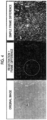
- Fig. 4 is a diagram for describing an example of an operation of the information processing device according to the first embodiment of the present disclosure.
- the information processing device 1 is a device that processes an image captured by an imaging unit 21 mounted in a moving body 2 in the information processing system 100, and performs predetermined information processing for detecting a predetermined detection target such as gas leakage.
- the information processing system 100 includes an information processing device 1 and a moving body 2.
- the moving body 2 is a drone.
- the moving body 2 is not limited to the drone (unmanned aerial vehicle), and may be, for example, a manned fixed wing aircraft or rotary wing aircraft, a satellite, a moving body that moves in contact with the ground or the water surface, or a moving body that moves in water.
- the detection target is not limited to the gas leakage, and for example, the presence or absence of the detection target or the movement of the detection target may appear in a difference between the frames of the captured images of the plurality of frames (for example, a difference in a brightness value or a pixel value for each pixel).
- the imaging unit 21 may capture a visible light image, may capture an infrared image, or may capture a visible light image and an infrared image in combination.
- examples of the detection target include a colorless and transparent gas such as carbon dioxide, methane, and ammonia, smoke, and a colored gas, but the present disclosure is not limited thereto.
- the information processing device 1 is configured by using a computer, and includes an acquisition unit 11, a registration unit 12, a difference calculation unit 13, and a storage unit 14 as a functional configuration composed of a combination of hardware, such as the computer and a peripheral device thereof, and software, such as a program executed by the computer. It should be noted that the information processing device 1 may receive the image data captured by the imaging unit 21 via wireless communication and process the image data in substantially real time, or may store the image data in a predetermined storage device and process the image data later. In addition, the information processing device 1 may be mounted on the moving body 2 together with the imaging unit 21.
- the information processing device 1 sequentially performs processing of detecting the detection target on the basis of the difference information between the frames in the images of the plurality of frames captured by the imaging unit 21.
- one image processing for two images two frames
- one of the two images is referred to as an original image
- the other image is referred to as a background image.
- the background image is an image that is a reference in a case in which the difference is calculated, and is an image on a side to be performed registration (to be changed) with respect to the original image (with the original image as a reference) in the registration processing described below.
- the background image is an (n-x)-th frame image.
- n is a natural number (or an integer of 0 or more) representing a frame number of the image captured by the imaging unit 21, and x is an integer of 1 or more.
- x is an integer of 1 or more.
- the order of the first image and the second image according to the present disclosure is relative, and one of the original image or the background image corresponds to the first image and the other corresponds to the second image.
- the value of x (the frame interval between the two images) can be set in accordance with, for example, the moving speed of the moving body 2.
- the acquisition unit 11 provided in the information processing device 1 acquires an original image and a background image captured by the imaging unit 21 mounted on the moving body 2 in different frames.
- the acquisition by the acquisition unit 11 includes acquisition from the imaging unit 21 via wireless communication and acquisition from the imaging unit 21 via wireless communication, storage in, for example, the storage unit 14, and acquisition from the storage unit 14.
- the registration unit 12 performs registration between the original image and the background image.
- the registration unit 12 performs registration of the background image with respect to the original image.
- the registration is a process of moving, rotating, and deforming one image to match the other image such that the position, the size, and the shape of the same subject are the same between two images, and is also referred to as image registration or the like.
- the method of performing registration is not limited, and for example, a method of moving the images in horizontal and vertical directions such that the sum of the brightness values of the respective pixels of the two images is minimized as described below, a method described in NPL 1 or the like can be used. In the method of NPL 1, the estimation results of the enlargement/reduction and the rotation amount between the two images are used for the registration.
- the difference calculation unit 13 calculates a difference between the background image and the original image performed registration the registration unit 12 for each corresponding pixel (pixel at the same position). For example, in a case where the background image and the original image are color images, the difference in the pixel value may be calculated for each pixel and each component, or the difference in the brightness value may be calculated for each pixel after conversion into the brightness value. In addition, in a case of an image of a grayscale scale, a difference in the brightness value (pixel value) is calculated for each pixel. It should be noted that the difference calculation unit 13 stores the calculation result of the difference in the storage unit 14 or displays the calculation result of the difference on a predetermined display unit. In the present embodiment, the difference calculation unit 13 stores or displays the calculation result, which is referred to as output.
- the storage unit 14 stores the image data captured by the imaging unit 21 or stores the calculation result by the difference calculation unit 13.
- the processing shown in Fig. 2 is an example of processing for each of one original image and one background image.
- the processing shown in Fig. 3 is an example of the registration processing executed in step S13 of Fig. 2 .
- the acquisition unit 11 acquires the original image (n-th frame) (step S11).
- the acquisition unit 11 acquires the background image ((n - x)th frame) (step S12).
- the registration unit 12 executes processing of performing registration of the background image with respect to the original image (step S13).
- the registration unit 12 stores -XL in the variable dx (step S21).
- the value of the variable dx is a value representing how many pixels the background image is moved in the X direction (horizontal direction).
- -XL represents the number of pixels to be moved first, and in this example, the background image is moved from the -XL pixel to the +XL pixel in the X direction.
- the registration unit 12 creates an image in which the background image is shifted by dx pixels in the X direction (step S22).
- step S22 the pixel at the end of the movement source is padded with zero.
- the registration unit 12 obtains a sum Sx_dx of the differences in the brightness values for each pixel between the original image and the image shifted in step S22 (step S23).
- "dx" of the sum Sx_dx is a variable "sum Sx" as a subscript, and a numerical value representing the movement amount is set.
- the registration unit 12 increases the variable dx by only 1 (step S24).
- the registration unit 12 determines whether or not the variable dx is greater than the constant XL (step S25). In a case where the variable dx is not greater than the constant XL (step S25: NO), the registration unit 12 executes the processing after step S22 again.
- the registration unit 12 stores -YL in the variable dy (step S26).
- the value of the variable dy is a value representing how many pixels the background image is moved in the Y direction (vertical direction).
- -YL represents the number of pixels to be first moved, and in this example, the background image is moved from the -YL pixel to the +YL pixel in the Y direction.
- the registration unit 12 creates an image in which the background image is shifted by dy pixels in the Y direction (step S27).
- step S27 the pixel at the end of the movement source is padded with zero.
- the registration unit 12 obtains a sum Sy_dy of the differences in the brightness values for each pixel between the original image and the image shifted in step S27 (step S28).
- "dy" of the sum Sy_dy is a variable "sum Sy" as a subscript, and a numerical value representing the movement amount is set.
- the registration unit 12 increases the variable dy by only 1 (step S29).
- step S30 determines whether or not the variable dy is greater than the constant YL (step S30). In a case where the variable dy is not greater than the constant YL (step S30: NO), the registration unit 12 executes the processing after step S27 again.
- the registration unit 12 determines the subscript "dx" of the minimum sum (Sx_dx) as the movement amount in the X direction (dx) and the subscript "dy" of the minimum sum (Sy_dy) as the movement amount in the Y direction (dy) (step S31).
- the registration unit 12 creates a background image performed registration by shifting the background image by the movement amount dx in the X direction and the movement amount dy in the Y direction (step S32).
- step S14 of Fig. 2 the difference calculation unit 13 calculates the difference between the original image and the background image performed registration by the registration unit 12 in step S13 (step S32 in Fig. 3 ) (step S14).
- step S15 the difference calculation unit 13 outputs the calculation result (step S15).
- Fig. 4 shows an example of the original image, an image showing a calculation result of a difference between the registered background image and the original image (hereinafter, referred to as an image of "registration + frame difference”), and an image showing a calculation result of a difference between the unregistered background image and the original image (hereinafter, referred to as an image of "simple frame difference").
- the brightness value is small (close to black) in a case where the difference is small, and the brightness value is large (close to white) in a case where the difference is large.
- the original image includes carbon dioxide gas that has been experimentally jetted in a range surrounded by a broken line circle in the image of "registration + frame difference". Further, the imaging place is a rough ground. Since the image of "registration + frame difference” is calculated the difference by performing registration of the imaging positions, the movement of carbon dioxide gas is captured. On the other hand, in the image of the "simple frame difference", the difference information corresponding to the carbon dioxide gas is not extracted because the imaging position is changed. It should be noted that the registration processing is performed using the method described in NPL 1.
- the difference processing is performed after the position of the background (background image) is corrected, it is possible to suppress the influence of the movement or the vibration of the moving body 2 as compared with a case in which the position correction is not performed, and it is possible to easily detect the detection target.
- Fig. 5 is a diagram showing an example of a configuration of an information processing device according to a second embodiment of the present disclosure.
- Fig. 6 is a flowchart showing an example of an operation of the information processing device according to the second embodiment of the present disclosure.
- the information processing device 1a in the information processing system 100a according to the second embodiment is different from the information processing device 1 in the first embodiment shown Fig. 1 in that the out-of-focus correction unit 15 is newly provided, the registration unit 12a sets the original image and the background image processed by the out-of-focus correction unit 15 as processing targets, and the difference calculation unit 13a sets the original image and the background image processed by the out-of-focus correction unit 15 as processing targets.
- the out-of-focus correction unit 15 shown in Fig. 5 corrects an out-of-focus of the background image and the original image.
- the registration unit 12a performs registration between the background image in which the out-of-focus is corrected and the original image in which the out-of-focus is corrected.
- the difference calculation unit 13a calculates a difference between the registered background image subjected to out-of-focus correction and the original image subjected to out-of-focus correction.
- out-of-focus means a state in which the subject is not in focus.
- a method of the out-of-focus correction processing by the out-of-focus correction unit 15 is not limited.
- the out-of-focus correction processing may be, for example, processing of emphasizing a contour.
- a method of estimating a deterioration trajectory (point spread function (PSF)) of an image whose image quality is deteriorated by a blind deconvolution method or the like and restoring the image based on the estimated PSF may be used as the out-of-focus correction processing.
- PSF point spread function
- the acquisition unit 11 acquires the original image (n-th frame) (step S41).
- the acquisition unit 11 acquires the background image ((n - x)th frame) (step S42).
- the out-of-focus correction unit 15 executes out-of-focus correction processing on the original image and the background image (step S43).
- the registration unit 12a executes processing of performing registration of the background image subjected to out-of-focus correction with the original image subjected to out-of-focus correction (step S44).
- the difference calculation unit 13a calculates a difference between the original image subjected to the out-of-focus correction and the background image performed registration by the registration unit 12a in step S44 (step S45). Next, the difference calculation unit 13a outputs the calculation result (step S46).
- the present embodiment it is possible to improve the detection sensitivity of the detection target even for an out-of-focus image.
- the information processing device After performing registration of a background image and an original image captured by the imaging unit mounted on the moving body in different frames, a difference between the frames is calculated. Therefore, with the information processing device, the information processing method, and the program of the embodiment, it is possible to easily detect a detection target such as gas leakage.
- Fig. 7 is a schematic block diagram showing a configuration of a computer according to at least one embodiment.
- a computer 90 includes a processor 91, a main memory 92, a storage 93, and an interface 94.
- the above-described information processing devices 1 and 1a are mounted on the computer 90.
- the operation of each processing unit described above is stored in the storage 93 in a form of a program.
- the processor 91 reads the program from the storage 93, loads the program into the main memory 92, and performs the above-described processes in accordance with the program. Further, the processor 91 ensures a storage area corresponding to each storage unit described above in the main memory 92 in accordance with the program.
- the program may implement some of functions performed by the computer 90.
- the program may implement the functions in combination with another program already stored in the storage or in combination with another program installed on another device.
- the computer may include a custom large scale integrated circuit (LSI) such as a programmable logic device (PLD).
- LSI large scale integrated circuit
- PLD programmable logic device
- Examples of the PLD include a programmable array logic (PAL), a generic array logic (GAL), a complex programmable logic device (CPLD), and a field programmable gate array (FPGA).
- PAL programmable array logic
- GAL generic array logic
- CPLD complex programmable logic device
- FPGA field programmable gate array
- Examples of the storage 93 include a hard disk drive (HDD), a solid state drive (SSD), a magnetic disc, a magneto-optical disc, a compact disc read only memory (CD-ROM), a digital versatile disc read only memory (DVD-ROM), and a semiconductor memory.
- the storage 93 may be an internal medium directly connected to a bus of the computer 90, or may be an external medium connected to the computer 90 via the interface 94 or a communication line.
- the computer 90 receiving the distribution may load the program into the main memory 92, and may perform the above-described processes.
- the storage 93 is a non-temporary tangible storage medium.
- the information processing devices 1 and 1a described in each embodiment are understood as follows.
- the information processing device, the information processing method, and the program can easily detect a detection target such as gas leakage.
Landscapes
- Engineering & Computer Science (AREA)
- Physics & Mathematics (AREA)
- General Physics & Mathematics (AREA)
- Theoretical Computer Science (AREA)
- Computer Vision & Pattern Recognition (AREA)
- Quality & Reliability (AREA)
- Biochemistry (AREA)
- Pathology (AREA)
- Chemical & Material Sciences (AREA)
- Analytical Chemistry (AREA)
- Health & Medical Sciences (AREA)
- General Health & Medical Sciences (AREA)
- Immunology (AREA)
- Life Sciences & Earth Sciences (AREA)
- Computing Systems (AREA)
- Multimedia (AREA)
- Signal Processing (AREA)
- Image Analysis (AREA)
- Image Processing (AREA)
- Closed-Circuit Television Systems (AREA)
- Investigating Or Analysing Materials By Optical Means (AREA)
- Studio Devices (AREA)
Abstract
Description
- The present disclosure relates to an information processing device, an information processing method, and a program.
- Priority is claimed to
Japanese Patent Application No. 2022-135686, filed August 29, 2022 -
PTL 1 discloses a gas leakage monitoring device that enables easy monitoring of gas leakage or the like in a relatively wide range of monitoring targets. That is, the gas leakage monitoring device disclosed inPTL 1 includes a visible image camera and an infrared image camera mounted on a flying object, and an image processing unit that combines a difference image in which pixels having no difference between frames in an infrared image are made transparent and a visible image and displays the combined image on a display unit. According to the gas leakage monitoring device disclosed inPTL 1, even in a case of a leakage of a transparent gas having the same temperature as the ambient temperature, the leakage can be visualized as an image corresponding to an infrared absorption spectrum of the gas, and the difference in brightness of each pixel can be obtained between frames. Therefore, it is possible to easily ascertain the leakage situation according to the situation of the jetting that changes every moment or the situation of the flow due to the wind. In addition, according to the gas leakage monitoring device disclosed inPTL 1, the visible images are combined even in a case where the field of view is shifted between the frames due to the flight movement or the vibration of the flying object, and the contours of subjects that are not gases tend to be emphasized as differences, so the enhanced portion is likely to be buried in the contour portion of the visible image, or the contour portion is recognized and thus the enhanced portion is not conspicuous. As a result, since the visibility is improved, it is possible to easily monitor the gas leakage. - NPL 1 discloses an example of a technique for performing registration of an image.
- [PTL 1]
Japanese Unexamined Patent Application Publication No. 2022-13126 - [NPL 1] Yoshi Ri and Hiroshi Fujimoto, "Practical Algorithm Design for the FFT-based Robust Image Registration Method", The Transactions of the Institute of Electrical Engineers of Japan. D, A publication of Industry Applications Society, Vol. 139, No. 1, pp. 22-29, January 2019
- However, the gas leakage monitoring device disclosed in
PTL 1 improves visibility by using ease of recognition of a contour portion of a subject such as a structure in a visible image. Therefore, for example, in a case where the contour portion of the subject in the visible image is not easily recognized, there is a problem that the visibility cannot be improved. - The present disclosure has been made to solve the above-described problems, and an object of the present disclosure is to provide an information processing device, an information processing method, and a program capable of easily detecting a detection target such as gas leakage.
- In order to achieve the above object, an information processing device according to the present disclosure includes an acquisition unit that acquires a first image and a second image captured by an imaging unit mounted on a moving body in different frames, a registration unit that performs registration of the first image and the second image, and a difference calculation unit that calculates a difference between the registered first image and the registered second image.
- An information processing method according to the present disclosure includes a step of acquiring a first image and a second image captured by an imaging unit mounted on a moving body in different frames, a step of performing registration between the first image and the second image and, a step of calculating a difference between the registered first image and the registered second image.
- A program according to the present disclosure causing a computer to execute a step of acquiring a first image and a second image captured by an imaging unit mounted on a moving body in different frames, a step of performing registration between the first image and the second image, and a step of calculating a difference between the registered first image and the registered second image.
- According to the information processing device, the information processing method, and the program of the present disclosure, it is possible to easily detect a detection target such as gas leakage.
-
-
Fig. 1 is a diagram showing an example of a configuration of an information processing device according to a first embodiment of the present disclosure. -
Fig. 2 is a flowchart showing an example of an operation of the information processing device according to the first embodiment of the present disclosure. -
Fig. 3 is a flowchart showing an example of registration processing according to the first embodiment of the present disclosure. -
Fig. 4 is a diagram for describing an example of an operation of the information processing device according to the first embodiment of the present disclosure. -
Fig. 5 is a diagram showing an example of a configuration of an information processing device according to a second embodiment of the present disclosure. -
Fig. 6 is a flowchart showing an example of an operation of the information processing device according to the second embodiment of the present disclosure. -
Fig. 7 is a schematic block diagram showing a configuration of a computer according to at least one embodiment. - Hereinafter, an information processing device, an information processing method, and a program according to an embodiment of the present disclosure will be described with reference to the drawings. In each drawing, the same reference numerals will be assigned to the same or corresponding configurations, and description thereof will be omitted as appropriate.
-
Fig. 1 is a diagram showing an example of a configuration of an information processing device according to a first embodiment of the present disclosure.Fig. 2 is a flowchart showing an example of an operation of the information processing device according to the first embodiment of the present disclosure.Fig. 3 is a flowchart showing an example of registration processing according to the first embodiment of the present disclosure.Fig. 4 is a diagram for describing an example of an operation of the information processing device according to the first embodiment of the present disclosure. - As shown in
Fig. 1 , theinformation processing device 1 according to the present embodiment is a device that processes an image captured by animaging unit 21 mounted in a movingbody 2 in theinformation processing system 100, and performs predetermined information processing for detecting a predetermined detection target such as gas leakage. Theinformation processing system 100 includes aninformation processing device 1 and a movingbody 2. In the example shown inFig. 1 , themoving body 2 is a drone. However, the movingbody 2 is not limited to the drone (unmanned aerial vehicle), and may be, for example, a manned fixed wing aircraft or rotary wing aircraft, a satellite, a moving body that moves in contact with the ground or the water surface, or a moving body that moves in water. In addition, the detection target is not limited to the gas leakage, and for example, the presence or absence of the detection target or the movement of the detection target may appear in a difference between the frames of the captured images of the plurality of frames (for example, a difference in a brightness value or a pixel value for each pixel). Further, theimaging unit 21 may capture a visible light image, may capture an infrared image, or may capture a visible light image and an infrared image in combination. Furthermore, examples of the detection target include a colorless and transparent gas such as carbon dioxide, methane, and ammonia, smoke, and a colored gas, but the present disclosure is not limited thereto. - The
information processing device 1 is configured by using a computer, and includes anacquisition unit 11, aregistration unit 12, adifference calculation unit 13, and astorage unit 14 as a functional configuration composed of a combination of hardware, such as the computer and a peripheral device thereof, and software, such as a program executed by the computer. It should be noted that theinformation processing device 1 may receive the image data captured by theimaging unit 21 via wireless communication and process the image data in substantially real time, or may store the image data in a predetermined storage device and process the image data later. In addition, theinformation processing device 1 may be mounted on the movingbody 2 together with theimaging unit 21. It should be noted that theinformation processing device 1 sequentially performs processing of detecting the detection target on the basis of the difference information between the frames in the images of the plurality of frames captured by theimaging unit 21. However, in the following, one image processing for two images (two frames) will be mainly described. Further, in the present embodiment, one of the two images is referred to as an original image, and the other image is referred to as a background image. The background image is an image that is a reference in a case in which the difference is calculated, and is an image on a side to be performed registration (to be changed) with respect to the original image (with the original image as a reference) in the registration processing described below. Furthermore, for example, in a case where the original image is an n-th frame image, the background image is an (n-x)-th frame image. n is a natural number (or an integer of 0 or more) representing a frame number of the image captured by theimaging unit 21, and x is an integer of 1 or more. It should be noted that the order of the first image and the second image according to the present disclosure is relative, and one of the original image or the background image corresponds to the first image and the other corresponds to the second image. In addition, the value of x (the frame interval between the two images) can be set in accordance with, for example, the moving speed of themoving body 2. - The
acquisition unit 11 provided in theinformation processing device 1 acquires an original image and a background image captured by theimaging unit 21 mounted on the movingbody 2 in different frames. The acquisition by theacquisition unit 11 includes acquisition from theimaging unit 21 via wireless communication and acquisition from theimaging unit 21 via wireless communication, storage in, for example, thestorage unit 14, and acquisition from thestorage unit 14. - The
registration unit 12 performs registration between the original image and the background image. In the present embodiment, theregistration unit 12 performs registration of the background image with respect to the original image. The registration is a process of moving, rotating, and deforming one image to match the other image such that the position, the size, and the shape of the same subject are the same between two images, and is also referred to as image registration or the like. The method of performing registration is not limited, and for example, a method of moving the images in horizontal and vertical directions such that the sum of the brightness values of the respective pixels of the two images is minimized as described below, a method described inNPL 1 or the like can be used. In the method ofNPL 1, the estimation results of the enlargement/reduction and the rotation amount between the two images are used for the registration. - The
difference calculation unit 13 calculates a difference between the background image and the original image performed registration theregistration unit 12 for each corresponding pixel (pixel at the same position). For example, in a case where the background image and the original image are color images, the difference in the pixel value may be calculated for each pixel and each component, or the difference in the brightness value may be calculated for each pixel after conversion into the brightness value. In addition, in a case of an image of a grayscale scale, a difference in the brightness value (pixel value) is calculated for each pixel. It should be noted that thedifference calculation unit 13 stores the calculation result of the difference in thestorage unit 14 or displays the calculation result of the difference on a predetermined display unit. In the present embodiment, thedifference calculation unit 13 stores or displays the calculation result, which is referred to as output. - The
storage unit 14 stores the image data captured by theimaging unit 21 or stores the calculation result by thedifference calculation unit 13. - Next, an example of an operation of the
information processing device 1 will be described with reference toFigs. 2 and3 . The processing shown inFig. 2 is an example of processing for each of one original image and one background image. The processing shown inFig. 3 is an example of the registration processing executed in step S13 ofFig. 2 . - In the processing shown in
Fig. 2 , first, theacquisition unit 11 acquires the original image (n-th frame) (step S11). Next, theacquisition unit 11 acquires the background image ((n - x)th frame) (step S12). Next, theregistration unit 12 executes processing of performing registration of the background image with respect to the original image (step S13). - In the registration processing executed in step S13, as shown in
Fig. 3 , first, theregistration unit 12 stores -XL in the variable dx (step S21). The value of the variable dx is a value representing how many pixels the background image is moved in the X direction (horizontal direction). -XL represents the number of pixels to be moved first, and in this example, the background image is moved from the -XL pixel to the +XL pixel in the X direction. - Next, the
registration unit 12 creates an image in which the background image is shifted by dx pixels in the X direction (step S22). In step S22, the pixel at the end of the movement source is padded with zero. Next, theregistration unit 12 obtains a sum Sx_dx of the differences in the brightness values for each pixel between the original image and the image shifted in step S22 (step S23). "dx" of the sum Sx_dx is a variable "sum Sx" as a subscript, and a numerical value representing the movement amount is set. Next, theregistration unit 12 increases the variable dx by only 1 (step S24). Next, theregistration unit 12 determines whether or not the variable dx is greater than the constant XL (step S25). In a case where the variable dx is not greater than the constant XL (step S25: NO), theregistration unit 12 executes the processing after step S22 again. - On the other hand, in a case where the variable dx is greater than the constant XL (step S25: YES), the
registration unit 12 stores -YL in the variable dy (step S26). The value of the variable dy is a value representing how many pixels the background image is moved in the Y direction (vertical direction). -YL represents the number of pixels to be first moved, and in this example, the background image is moved from the -YL pixel to the +YL pixel in the Y direction. - Next, the
registration unit 12 creates an image in which the background image is shifted by dy pixels in the Y direction (step S27). In step S27, the pixel at the end of the movement source is padded with zero. Next, theregistration unit 12 obtains a sum Sy_dy of the differences in the brightness values for each pixel between the original image and the image shifted in step S27 (step S28). "dy" of the sum Sy_dy is a variable "sum Sy" as a subscript, and a numerical value representing the movement amount is set. Next, theregistration unit 12 increases the variable dy by only 1 (step S29). Next, theregistration unit 12 determines whether or not the variable dy is greater than the constant YL (step S30). In a case where the variable dy is not greater than the constant YL (step S30: NO), theregistration unit 12 executes the processing after step S27 again. - On the other hand, in a case where the variable dy is greater than the constant YL (step S30: YES), the
registration unit 12 determines the subscript "dx" of the minimum sum (Sx_dx) as the movement amount in the X direction (dx) and the subscript "dy" of the minimum sum (Sy_dy) as the movement amount in the Y direction (dy) (step S31). Next, theregistration unit 12 creates a background image performed registration by shifting the background image by the movement amount dx in the X direction and the movement amount dy in the Y direction (step S32). - Next, in step S14 of
Fig. 2 , thedifference calculation unit 13 calculates the difference between the original image and the background image performed registration by theregistration unit 12 in step S13 (step S32 inFig. 3 ) (step S14). Next, thedifference calculation unit 13 outputs the calculation result (step S15). -
Fig. 4 shows an example of the original image, an image showing a calculation result of a difference between the registered background image and the original image (hereinafter, referred to as an image of "registration + frame difference"), and an image showing a calculation result of a difference between the unregistered background image and the original image (hereinafter, referred to as an image of "simple frame difference"). It should be noted that, in the image showing the calculation result of the difference, the brightness value is small (close to black) in a case where the difference is small, and the brightness value is large (close to white) in a case where the difference is large. In addition, the original image includes carbon dioxide gas that has been experimentally jetted in a range surrounded by a broken line circle in the image of "registration + frame difference". Further, the imaging place is a rough ground. Since the image of "registration + frame difference" is calculated the difference by performing registration of the imaging positions, the movement of carbon dioxide gas is captured. On the other hand, in the image of the "simple frame difference", the difference information corresponding to the carbon dioxide gas is not extracted because the imaging position is changed. It should be noted that the registration processing is performed using the method described inNPL 1. - According to the present embodiment, since the difference processing is performed after the position of the background (background image) is corrected, it is possible to suppress the influence of the movement or the vibration of the moving
body 2 as compared with a case in which the position correction is not performed, and it is possible to easily detect the detection target. -
Fig. 5 is a diagram showing an example of a configuration of an information processing device according to a second embodiment of the present disclosure.Fig. 6 is a flowchart showing an example of an operation of the information processing device according to the second embodiment of the present disclosure. - As shown in
Fig. 5 , theinformation processing device 1a in theinformation processing system 100a according to the second embodiment is different from theinformation processing device 1 in the first embodiment shownFig. 1 in that the out-of-focus correction unit 15 is newly provided, theregistration unit 12a sets the original image and the background image processed by the out-of-focus correction unit 15 as processing targets, and thedifference calculation unit 13a sets the original image and the background image processed by the out-of-focus correction unit 15 as processing targets. - The out-of-
focus correction unit 15 shown inFig. 5 corrects an out-of-focus of the background image and the original image. In addition, theregistration unit 12a performs registration between the background image in which the out-of-focus is corrected and the original image in which the out-of-focus is corrected. Further, thedifference calculation unit 13a calculates a difference between the registered background image subjected to out-of-focus correction and the original image subjected to out-of-focus correction. - In addition, "out-of-focus" means a state in which the subject is not in focus. A method of the out-of-focus correction processing by the out-of-
focus correction unit 15 is not limited. The out-of-focus correction processing may be, for example, processing of emphasizing a contour. In addition, as the out-of-focus correction processing, for example, a method of estimating a deterioration trajectory (point spread function (PSF)) of an image whose image quality is deteriorated by a blind deconvolution method or the like and restoring the image based on the estimated PSF may be used. - Next, an example of an operation of the
information processing device 1a will be described with reference toFig. 6 . In the processing shown inFig. 6 , first, theacquisition unit 11 acquires the original image (n-th frame) (step S41). Next, theacquisition unit 11 acquires the background image ((n - x)th frame) (step S42). Next, the out-of-focus correction unit 15 executes out-of-focus correction processing on the original image and the background image (step S43). Next, theregistration unit 12a executes processing of performing registration of the background image subjected to out-of-focus correction with the original image subjected to out-of-focus correction (step S44). - Next, the
difference calculation unit 13a calculates a difference between the original image subjected to the out-of-focus correction and the background image performed registration by theregistration unit 12a in step S44 (step S45). Next, thedifference calculation unit 13a outputs the calculation result (step S46). - According to the present embodiment, it is possible to improve the detection sensitivity of the detection target even for an out-of-focus image.
- In the information processing device, the information processing method, and the program according to the above configuration, after performing registration of a background image and an original image captured by the imaging unit mounted on the moving body in different frames, a difference between the frames is calculated. Therefore, with the information processing device, the information processing method, and the program of the embodiment, it is possible to easily detect a detection target such as gas leakage.
- The embodiments of the present disclosure have been described in detail with reference to the drawings hereinbefore. However, the specific configuration is not limited to the embodiments, and includes design changes and the like within a scope not departing from the gist of the present disclosure.
-
Fig. 7 is a schematic block diagram showing a configuration of a computer according to at least one embodiment. - A
computer 90 includes aprocessor 91, amain memory 92, astorage 93, and aninterface 94. - The above-described
information processing devices computer 90. The operation of each processing unit described above is stored in thestorage 93 in a form of a program. Theprocessor 91 reads the program from thestorage 93, loads the program into themain memory 92, and performs the above-described processes in accordance with the program. Further, theprocessor 91 ensures a storage area corresponding to each storage unit described above in themain memory 92 in accordance with the program. - The program may implement some of functions performed by the
computer 90. For example, the program may implement the functions in combination with another program already stored in the storage or in combination with another program installed on another device. In another embodiment, in addition to the above-described configuration or instead of the above-described configuration, the computer may include a custom large scale integrated circuit (LSI) such as a programmable logic device (PLD). Examples of the PLD include a programmable array logic (PAL), a generic array logic (GAL), a complex programmable logic device (CPLD), and a field programmable gate array (FPGA). In this case, some or all of the functions implemented by the processor may be implemented by the integrated circuit. - Examples of the
storage 93 include a hard disk drive (HDD), a solid state drive (SSD), a magnetic disc, a magneto-optical disc, a compact disc read only memory (CD-ROM), a digital versatile disc read only memory (DVD-ROM), and a semiconductor memory. Thestorage 93 may be an internal medium directly connected to a bus of thecomputer 90, or may be an external medium connected to thecomputer 90 via theinterface 94 or a communication line. In addition, when the program is distributed to thecomputer 90 via the communication line, thecomputer 90 receiving the distribution may load the program into themain memory 92, and may perform the above-described processes. In at least one embodiment, thestorage 93 is a non-temporary tangible storage medium. - For example, the
information processing devices -
- (1)
Information processing devices acquisition unit 11 that acquires a first image and a second image captured by animaging unit 21 mounted on a movingbody 2 in different frames, aregistration unit difference calculation unit - (2) The
information processing device 1a according to a second aspect is the information processing device according to (1), further including an out-of-focus correction unit 15 that corrects an out-of-focus of the first image and the second image, in which theregistration unit 12a performs registration between the first image and the second image in which the out-of-focus is corrected. According to the present aspect, it is possible to improve the detection sensitivity for the out-of-focus image. - (3) The
information processing devices - According to the above-described one aspect, the information processing device, the information processing method, and the program can easily detect a detection target such as gas leakage.
-
- 1, 1a: information processing device
- 2: moving body
- 11: acquisition unit
- 12, 12a: registration unit
- 13, 13a: difference calculation unit
- 14: storage unit
- 15: out-of-focus correction unit
Claims (5)
- An information processing device comprising:an acquisition unit that acquires a first image and a second image captured by an imaging unit mounted on a moving body in different frames;a registration unit that performs registration of the first image and the second image; anda difference calculation unit that calculates a difference between the registered first image and the registered second image.
- The information processing device according to claim 1, further comprising:an out-of-focus correction unit that corrects an out-of-focus of the first image and the second image,wherein the registration unit performs registration between the first image and the second image in which the out-of-focus is corrected.
- The information processing device according to claim 1 or 2,
wherein a frame interval between the first image and the second image is set in accordance with a moving speed of the moving body. - An information processing method comprising:a step of acquiring a first image and a second image captured by an imaging unit mounted on a moving body in different frames;a step of performing registration between the first image and the second image; anda step of calculating a difference between the registered first image and the registered second image.
- A program causing a computer to execute:a step of acquiring a first image and a second image captured by an imaging unit mounted on a moving body in different frames;a step of performing registration between the first image and the second image; anda step of calculating a difference between the registered first image and the registered second image.
Applications Claiming Priority (2)
| Application Number | Priority Date | Filing Date | Title |
|---|---|---|---|
| JP2022135686A JP2024032176A (en) | 2022-08-29 | 2022-08-29 | Information processing device, information processing method and program |
| PCT/JP2023/025281 WO2024048080A1 (en) | 2022-08-29 | 2023-07-07 | Information processing device, information processing method, and program |
Publications (2)
| Publication Number | Publication Date |
|---|---|
| EP4561086A1 true EP4561086A1 (en) | 2025-05-28 |
| EP4561086A4 EP4561086A4 (en) | 2025-10-29 |
Family
ID=90099529
Family Applications (1)
| Application Number | Title | Priority Date | Filing Date |
|---|---|---|---|
| EP23859850.2A Pending EP4561086A4 (en) | 2022-08-29 | 2023-07-07 | Information processing device, information processing method, and program |
Country Status (6)
| Country | Link |
|---|---|
| US (1) | US20260065493A1 (en) |
| EP (1) | EP4561086A4 (en) |
| JP (1) | JP2024032176A (en) |
| CN (1) | CN119698845A (en) |
| AU (1) | AU2023333968B2 (en) |
| WO (1) | WO2024048080A1 (en) |
Family Cites Families (8)
| Publication number | Priority date | Publication date | Assignee | Title |
|---|---|---|---|---|
| JP3892059B2 (en) * | 1995-03-07 | 2007-03-14 | 松下電器産業株式会社 | Moving body tracking device |
| US6128047A (en) * | 1998-05-20 | 2000-10-03 | Sony Corporation | Motion estimation process and system using sparse search block-matching and integral projection |
| JP3807331B2 (en) * | 2002-03-06 | 2006-08-09 | 日産自動車株式会社 | Camera dirt detection device and camera dirt detection method |
| JP2008219063A (en) * | 2007-02-28 | 2008-09-18 | Sanyo Electric Co Ltd | Apparatus and method for monitoring vehicle's surrounding |
| JP2015033019A (en) * | 2013-08-02 | 2015-02-16 | シャープ株式会社 | Image processing device, image display device, program, and recording medium |
| JP6882885B2 (en) * | 2016-12-16 | 2021-06-02 | 株式会社デンソーテン | Obstacle detection device and obstacle detection method |
| JP7514675B2 (en) * | 2020-07-03 | 2024-07-11 | 山九株式会社 | Gas Leak Monitoring Device |
| JP7751389B2 (en) | 2021-03-05 | 2025-10-08 | 能美防災株式会社 | Fire Information Analysis System |
-
2022
- 2022-08-29 JP JP2022135686A patent/JP2024032176A/en active Pending
-
2023
- 2023-07-07 WO PCT/JP2023/025281 patent/WO2024048080A1/en not_active Ceased
- 2023-07-07 EP EP23859850.2A patent/EP4561086A4/en active Pending
- 2023-07-07 AU AU2023333968A patent/AU2023333968B2/en active Active
- 2023-07-07 CN CN202380059446.9A patent/CN119698845A/en active Pending
- 2023-07-07 US US19/106,302 patent/US20260065493A1/en active Pending
Also Published As
| Publication number | Publication date |
|---|---|
| CN119698845A (en) | 2025-03-25 |
| EP4561086A4 (en) | 2025-10-29 |
| US20260065493A1 (en) | 2026-03-05 |
| AU2023333968A1 (en) | 2025-03-06 |
| AU2023333968B2 (en) | 2026-04-23 |
| JP2024032176A (en) | 2024-03-12 |
| WO2024048080A1 (en) | 2024-03-07 |
Similar Documents
| Publication | Publication Date | Title |
|---|---|---|
| CN110956597B (en) | Device and method for automatic image improvement in a vehicle | |
| US10943141B2 (en) | Object detection device and object detection method | |
| EP2913779B1 (en) | Method for product recognition from multiple images | |
| JP6232502B2 (en) | Artificial vision system | |
| EP3503027B1 (en) | Cluttered background removal from imagery for object detection | |
| JP6233869B2 (en) | Image processing apparatus, image processing apparatus control method, and program | |
| CN112396634B (en) | Moving object detection method, moving object detection device, vehicle and storage medium | |
| US11457158B2 (en) | Location estimation device, location estimation method, and program recording medium | |
| JPWO2011077659A1 (en) | Image processing apparatus, imaging apparatus, and image processing method | |
| EP4388504B1 (en) | Saliency-based automatic target detection system | |
| WO2010089836A1 (en) | Image processing device | |
| KR20150075505A (en) | Apparatus and method for providing other ship information based on image | |
| AU2023333968B2 (en) | Information processing device, information processing method, and program | |
| KR20170134077A (en) | Method and system for detecting ship using image of uav | |
| US9900509B2 (en) | Frame registration for imaging sensors in motion | |
| US12026852B2 (en) | Instrument qualified visual range (IQVR) image processing artifact mitigation | |
| US9970766B2 (en) | Platform-mounted artificial vision system | |
| US20260087734A1 (en) | Image processing device, image processing method, and program | |
| Gurtner et al. | Vibration compensation for fisheye lenses in UAV applications | |
| Souvalioti et al. | Lightweight RAW Object Detection for Automated Driving | |
| JP2004144505A (en) | Astronomical detector | |
| KR101616789B1 (en) | Apparatus for skyline detection and method for skyline detection | |
| CN121458578A (en) | Dynamic image enhancement method and system of motion carrier in dynamic scene | |
| US20190306509A1 (en) | Video processing apparatus for processing video data captured by video capturing apparatus mounted on vehicle | |
| JPWO2021131364A1 (en) | Reflection removal engine generation method, program, reflection removal engine generation device, reflection removal device, abnormality detection method and component detection method |
Legal Events
| Date | Code | Title | Description |
|---|---|---|---|
| STAA | Information on the status of an ep patent application or granted ep patent |
Free format text: STATUS: THE INTERNATIONAL PUBLICATION HAS BEEN MADE |
|
| PUAI | Public reference made under article 153(3) epc to a published international application that has entered the european phase |
Free format text: ORIGINAL CODE: 0009012 |
|
| STAA | Information on the status of an ep patent application or granted ep patent |
Free format text: STATUS: REQUEST FOR EXAMINATION WAS MADE |
|
| 17P | Request for examination filed |
Effective date: 20250224 |
|
| AK | Designated contracting states |
Kind code of ref document: A1 Designated state(s): AL AT BE BG CH CY CZ DE DK EE ES FI FR GB GR HR HU IE IS IT LI LT LU LV MC ME MK MT NL NO PL PT RO RS SE SI SK SM TR |
|
| REG | Reference to a national code |
Ref country code: DE Ref legal event code: R079 Free format text: PREVIOUS MAIN CLASS: H04N0023600000 Ipc: G06T0007320000 |
|
| A4 | Supplementary search report drawn up and despatched |
Effective date: 20250925 |
|
| RIC1 | Information provided on ipc code assigned before grant |
Ipc: G06T 7/32 20170101AFI20250919BHEP Ipc: G06T 7/00 20170101ALI20250919BHEP Ipc: G01N 21/94 20060101ALI20250919BHEP Ipc: H04N 23/958 20230101ALI20250919BHEP |
|
| DAV | Request for validation of the european patent (deleted) | ||
| DAX | Request for extension of the european patent (deleted) |