EP4560863A2 - Power distribution module allowing maintenance without power interruption, and power distribution system - Google Patents
Power distribution module allowing maintenance without power interruption, and power distribution system Download PDFInfo
- Publication number
- EP4560863A2 EP4560863A2 EP24176438.0A EP24176438A EP4560863A2 EP 4560863 A2 EP4560863 A2 EP 4560863A2 EP 24176438 A EP24176438 A EP 24176438A EP 4560863 A2 EP4560863 A2 EP 4560863A2
- Authority
- EP
- European Patent Office
- Prior art keywords
- unit
- input
- output
- switch unit
- busbar
- Prior art date
- Legal status (The legal status is an assumption and is not a legal conclusion. Google has not performed a legal analysis and makes no representation as to the accuracy of the status listed.)
- Pending
Links
Images


Classifications
-
- H—ELECTRICITY
- H02—GENERATION; CONVERSION OR DISTRIBUTION OF ELECTRIC POWER
- H02J—ELECTRIC POWER NETWORKS; CIRCUIT ARRANGEMENTS OR SYSTEMS FOR SUPPLYING OR DISTRIBUTING ELECTRIC POWER; SYSTEMS FOR STORING ELECTRIC ENERGY
- H02J1/00—Circuit arrangements for DC mains or DC distribution networks
- H02J1/001—Hot plugging or unplugging of load or power modules to or from power distribution networks
-
- H—ELECTRICITY
- H02—GENERATION; CONVERSION OR DISTRIBUTION OF ELECTRIC POWER
- H02B—BOARDS, SUBSTATIONS OR SWITCHING ARRANGEMENTS FOR THE SUPPLY OR DISTRIBUTION OF ELECTRIC POWER
- H02B1/00—Frameworks, boards, panels, desks, casings; Details of substations or switching arrangements
- H02B1/26—Casings; Parts thereof or accessories therefor
- H02B1/30—Cabinet-type casings; Parts thereof or accessories therefor
- H02B1/32—Mounting of devices therein
-
- H—ELECTRICITY
- H02—GENERATION; CONVERSION OR DISTRIBUTION OF ELECTRIC POWER
- H02B—BOARDS, SUBSTATIONS OR SWITCHING ARRANGEMENTS FOR THE SUPPLY OR DISTRIBUTION OF ELECTRIC POWER
- H02B1/00—Frameworks, boards, panels, desks, casings; Details of substations or switching arrangements
- H02B1/20—Bus-bar or other wiring layouts, e.g. in cubicles, in switchyards
- H02B1/21—Bus-bar arrangements for rack-mounted devices with withdrawable units
-
- H—ELECTRICITY
- H02—GENERATION; CONVERSION OR DISTRIBUTION OF ELECTRIC POWER
- H02B—BOARDS, SUBSTATIONS OR SWITCHING ARRANGEMENTS FOR THE SUPPLY OR DISTRIBUTION OF ELECTRIC POWER
- H02B1/00—Frameworks, boards, panels, desks, casings; Details of substations or switching arrangements
- H02B1/24—Circuit arrangements for boards or switchyards
-
- H—ELECTRICITY
- H02—GENERATION; CONVERSION OR DISTRIBUTION OF ELECTRIC POWER
- H02B—BOARDS, SUBSTATIONS OR SWITCHING ARRANGEMENTS FOR THE SUPPLY OR DISTRIBUTION OF ELECTRIC POWER
- H02B1/00—Frameworks, boards, panels, desks, casings; Details of substations or switching arrangements
- H02B1/26—Casings; Parts thereof or accessories therefor
- H02B1/30—Cabinet-type casings; Parts thereof or accessories therefor
- H02B1/32—Mounting of devices therein
- H02B1/34—Racks
-
- H—ELECTRICITY
- H02—GENERATION; CONVERSION OR DISTRIBUTION OF ELECTRIC POWER
- H02B—BOARDS, SUBSTATIONS OR SWITCHING ARRANGEMENTS FOR THE SUPPLY OR DISTRIBUTION OF ELECTRIC POWER
- H02B3/00—Apparatus specially adapted for the manufacture, assembly, or maintenance of boards or switchgear
-
- H—ELECTRICITY
- H02—GENERATION; CONVERSION OR DISTRIBUTION OF ELECTRIC POWER
- H02J—ELECTRIC POWER NETWORKS; CIRCUIT ARRANGEMENTS OR SYSTEMS FOR SUPPLYING OR DISTRIBUTING ELECTRIC POWER; SYSTEMS FOR STORING ELECTRIC ENERGY
- H02J9/00—Circuit arrangements for emergency or stand-by power supply, e.g. for emergency lighting
- H02J9/04—Circuit arrangements for emergency or stand-by power supply, e.g. for emergency lighting in which the distribution system is disconnected from the normal source and connected to a standby source
- H02J9/06—Circuit arrangements for emergency or stand-by power supply, e.g. for emergency lighting in which the distribution system is disconnected from the normal source and connected to a standby source with automatic change-over, e.g. UPS systems
- H02J9/062—Circuit arrangements for emergency or stand-by power supply, e.g. for emergency lighting in which the distribution system is disconnected from the normal source and connected to a standby source with automatic change-over, e.g. UPS systems for AC powered loads
-
- H—ELECTRICITY
- H05—ELECTRIC TECHNIQUES NOT OTHERWISE PROVIDED FOR
- H05K—PRINTED CIRCUITS; CASINGS OR CONSTRUCTIONAL DETAILS OF ELECTRIC APPARATUS; MANUFACTURE OF ASSEMBLAGES OF ELECTRICAL COMPONENTS
- H05K7/00—Constructional details common to different types of electric apparatus
- H05K7/14—Mounting supporting structure in casing or on frame or rack
- H05K7/1485—Servers; Data center rooms, e.g. 19-inch computer racks
- H05K7/1488—Cabinets therefor, e.g. chassis or racks or mechanical interfaces between blades and support structures
- H05K7/1492—Cabinets therefor, e.g. chassis or racks or mechanical interfaces between blades and support structures having electrical distribution arrangements, e.g. power supply or data communications
Definitions
- the present disclosure relates to the field of power supply technology, and in particular to a power distribution module allowing maintenance without power interruption and a power distribution system.
- a conventional prefabricated power module includes a low-voltage distribution cabinet and an uninterruptible power supply (UPS).
- UPS uninterruptible power supply
- the UPS as an important component, is often used in conjunction with an UPS input-output switch.
- An input terminal and output terminal of the UPS input-output switch, a horizontal bus cable, and a distribution bus cable are not isolated from each other, resulting in a great limitation.
- the UPS fails, the UPS cannot be removed separately for repairing or replacement, without powering off the power distribution system.
- power outage is a serious matter and leads to significant economic loss.
- the present disclosure provides a power distribution module allowing maintenance without power interruption and a power distribution system.
- a UPS unit can be repaired or replaced without powering off the power distribution system.
- the power distribution module includes a cabinet and a mains horizontal busbar unit, a distribution busbar unit, an input switch unit, an input connection unit, an output connection unit, an output switch unit, an output horizontal busbar unit and a UPS unit which are installed in the cabinet in a modular design.
- the cabinet includes a rack and an isolation housing for insulation isolation assembled on the rack.
- An output terminal of the mains horizontal busbar unit is connected to an input terminal of the distribution busbar unit, an output terminal of the distribution busbar unit is connected to an input terminal of the input switch unit, an output terminal of the input switch unit is connected to an input terminal of the input connection unit, an output terminal of the input connection unit is connected to an input terminal of the UPS unit, an input terminal of the output connection unit is connected to an output terminal of the UPS unit, an output terminal of the output connection unit is connected to an input terminal of the output switch unit, and an output terminal of the output switch unit is connected to an input terminal of the output horizontal busbar unit.
- the input switch unit and the output switch unit are capable of controlling power-on and power-off of the power distribution module.
- the isolation housing is provided around the mains horizontal busbar unit, around the distribution busbar unit, around the input switch unit, around the output switch unit and around the output horizontal busbar unit, for isolating the mains horizontal busbar unit, the distribution busbar unit, the input switch unit, the output switch unit and the output horizontal busbar unit individually from each other.
- an isolation housing is provided around the UPS unit for isolating the UPS unit individually.
- the input terminal of the UPS unit includes a main input interface, a bypass input interface and a direct-current, DC, input interface;
- the input connection unit includes a main input connection unit, a bypass input connection unit, and a DC input connection unit; an input terminal of the main input connection unit is connected to the output terminal of the input switch unit, and an output terminal of the main input connection unit is for connection to the main input interface; an input terminal of the bypass input connection unit is connected to the output terminal of the input switch unit, and an output terminal of the bypass input connection unit is for connection to the bypass input interface; and an output terminal of the DC input connection unit is for connection to the DC input interface, and an input terminal of the DC input connection unit is for connection to a DC input cable.
- the input switch unit includes a main input switch unit and a bypass input switch unit; an input terminal of the main input switch unit is connected to the output terminal of the distribution busbar unit, and an output terminal of the main input switch unit is connected to an input terminal of the main input connection unit; an input terminal of the bypass input switch unit is connected to the output terminal of the distribution busbar unit, and an output terminal of the bypass input switch unit is connected to an input terminal of the bypass output connection unit; and the main input switch unit and the bypass input switch unit are in a modular design, and the isolation housing is provided around the main input switch unit and around the bypass input switch unit, for isolating the main input switch unit and the bypass input switch unit individually.
- the power distribution module further includes a DC input switch unit installed in the cabinet, where an input terminal of the DC input switch unit is for connection to a DC input cable, and an output terminal of the DC input switch unit is connected to the input terminal of the DC input connection unit; and the DC input switch unit is in a modular design and is surrounded by a isolation housing, so that the DC input switch unit is isolated individually.
- the power distribution module further includes a grounding unit and a grounding busbar unit installed in the cabinet; where a casing of the UPS unit is connected to an input terminal of the grounding busbar unit via the grounding unit, and the input terminal of the grounding busbar unit is connected to the rack, the mains horizontal busbar unit, the distribution busbar unit, the input switch unit, the output switch unit and the output horizontal busbar unit, and an output terminal of the grounding busbar unit is for connecting to a grounding grid of a power distribution system; and the grounding unit and the grounding busbar unit are in a modular design.
- the mains horizontal busbar unit, the distribution busbar unit, the main input connection unit, the bypass input connection unit, the DC input connection unit, the output connection unit, the output horizontal busbar unit, the grounding unit, and the grounding busbar unit are all copper busbars.
- mains horizontal busbar unit and the output horizontal busbar unit are in a segmented form and have reserved expansion connection holes.
- the power distribution module further includes a communication line channel unit and a monitoring unit installed in the cabinet; where the communication line channel unit is provided with channels for laying a communication line and a communication control line, the communication line is for signal connection between the monitoring unit and the UPS unit, and the communication control line is for parallel connection between power distribution modules; the monitoring unit has signal connection to the mains horizontal busbar unit, the distribution busbar unit, the input switch unit, the UPS unit, the output switch unit and the output horizontal busbar unit; and the isolation housing is provided around the communication line channel unit and the monitoring unit, for isolating the communication line channel unit and the monitoring unit individually.
- the cabinet includes a first assembly chamber and a second assembly chamber located at a side of the first assembly chamber along a first direction
- the first assembly chamber includes a first assembly sub-chamber and a second assembly sub-chamber arranged side by side along a second direction
- the UPS unit is located in the first assembly sub-chamber
- the input switch unit and the output switch unit are located in the second assembly sub-chamber and arranged along the first direction
- the main input connection unit, the bypass input connection unit, the DC input connection unit and the output connection unit are located in the second assembly sub-chamber and on a same side of the input switch unit and the output switch unit along a third direction, where the first direction, the second direction and the third direction are perpendicular to each other
- the mains horizontal busbar unit and the output horizontal busbar unit are located in the second assembly chamber.
- the monitoring unit is located at a side of the main input connection unit, the bypass input connection unit, the DC input connection unit and the output connection unit facing away from the input switch unit and the output switch unit, a plate for insulation isolation is provided between the monitoring unit and the main input connection unit, the bypass input connection unit, the DC input connection unit and the output connection unit.
- a detachable baffle is provided in the first assembly chamber to reserve spare space for assembling the UPS unit.
- the power distribution system includes at least two power distribution modules allowing maintenance without power interruption according to any one of the above solutions, where the at least two power distribution modules allowing maintenance without power interruption are connected in parallel.
- the power distribution module allowing maintenance without power interruption includes a cabinet and a mains horizontal busbar unit, a distribution busbar unit, an input switch unit, an input connection unit, an output connection unit, an output switch unit, and an output horizontal busbar unit which are installed in the cabinet and are in a modular design.
- the cabinet may include a rack and an isolation housing assembled on the rack.
- the isolation housing is provided around the mains horizontal busbar unit, around the distribution busbar unit, around the input switch unit, around the output switch unit and around the output horizontal busbar unit.
- the mains horizontal busbar unit, the distribution busbar unit, the input switch unit, the output switch unit and the output horizontal busbar unit can be isolated individually from each other.
- switches of the input switch unit and the output switch unit which are connected to the UPS unit may be simply opened to power off the power distribution module.
- the UPS unit can be repaired or replaced without powering off the power distribution system. In this way, a normal power supply of the power distribution system can be ensured, there is no need to limit a duration of repairing or replacement of the UPS unit, and an economic loss can be avoided.
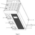
- 100 Cabinet; 101: Rack; 102: Isolation housing; 1: Mains horizontal busbar unit; 2: Distribution busbar unit; 3: Main input switch unit; 4: Bypass input switch unit; 5: Main input connection unit; 6: Bypass input connection unit; 7: DC input connection unit; 8: UPS unit; 9: Output connection unit; 10: Output switch unit; 11: Output horizontal busbar unit; 12: Grounding unit; 13: Grounding busbar unit; 14: Communication line channel unit; 15: Monitoring unit; 16: Plate; 17: Fixing part; 18: Baffle; 19: Communication line
- the power distribution module includes a cabinet 100 and a mains horizontal busbar unit 1, a distribution busbar unit 2, an input switch unit, an input connection unit, an output connection unit 9, an output switch unit 10, an output horizontal busbar unit 11 and a UPS unit which are installed in the cabinet 100 and are in a modular design.
- the cabinet 100 includes a rack 101 and an isolation housing 102 for insulation isolation assembled on the rack 101.
- An output terminal of the mains horizontal busbar unit 1 is connected to an input terminal of the distribution busbar unit 2
- an output terminal of the distribution busbar unit 2 is connected to an input terminal of the input switch unit
- an output terminal of the input switch unit is connected to an input terminal of the input connection unit
- an output terminal of the input connection unit is connected to an input terminal of the UPS unit 8
- an input terminal of the output connection unit 9 is connected to an output terminal of the UPS unit 8
- an output terminal of the output connection unit 9 is connected to an input terminal of the output switch unit 10
- the input switch unit and the output switch unit 10 are capable of controlling power-on and power-off of the power distribution module.
- the isolation housing 102 is provided around the mains horizontal busbar unit 1, around the distribution busbar unit 2, around the input switch unit, around the output switch unit 10 and around the output horizontal busbar unit 11, for isolating the mains horizontal busbar unit 1, the distribution busbar unit 2, the input switch unit, the output switch unit 10 and the output horizontal busbar unit 11 individually from each other.
- the power distribution module allowing maintenance without power interruption includes the cabinet 100 and the mains horizontal busbar unit 1, the distribution busbar unit 2, the input switch unit, the input connection unit, the output connection unit 9, the output switch unit 10, and the output horizontal busbar unit 11 which are installed in the cabinet 100 and are in a modular design.
- the cabinet 100 may include a rack 101 and an isolation housing 102 assembled on the rack 101.
- the isolation housing 102 is provided around the mains horizontal busbar unit 1, around the distribution busbar unit 2, around the input switch unit, around the output switch unit 10 and around the output horizontal busbar unit 11.
- the mains horizontal busbar unit 1, the distribution busbar unit 2, the input switch unit, the output switch unit 10 and the output horizontal busbar unit 11 can be isolated individually from each other.
- switches of the input switch unit and the output switch unit 10 which are connected to the UPS unit 8 may be simply opened to power off the power distribution module.
- the UPS unit 8 under a safe condition of not touching the mains horizontal busbar unit 1, the distribution busbar unit 2 and the input switch unit in the power distribution module, the UPS unit 8 can be repaired or replaced without powering off the power distribution system. In this way, a normal power supply of the power distribution system can be ensured, there is no need to limit a duration of repairing or replacement of the UPS unit 8, and an economic loss can be avoided.
- the isolation housing 102 may be provided around the UPS unit 8 for isolating the UPS unit 8 individually.
- an existing low-voltage distribution cabinet and an uninterruptible power supply (UPS) can be combined into one distribution cabinet, and a connection structure of the distribution cabinet can be optimized. Thereby, assembly of the distribution cabinet is facilitated before leaving a factory.
- the distribution cabinet may be transported to a data center by using a lift or crane, so as to improve an efficiency of constructing the power distribution system on site the data center. In a case where the UPS needs to be repaired or replaced, the safety of the operator can be ensured, and a normal supply of the power system can be ensured without powering off the power distribution system.
- the input terminal of the UPS unit 8 may include a main input interface, a bypass input interface and a DC input interface.
- the input connection unit may include a main input connection unit 5, a bypass input connection unit 6 and a DC input connection unit 7.
- An input terminal of the main input connection unit 5 may be connected to an output terminal of the input switch unit, and an output terminal of the main input connection unit 5 is for connection to the main input interface.
- An input terminal of the bypass input connection unit 6 is connected to an output terminal of the input switch unit, and an output terminal of the bypass input connection unit 6 is for connection to the bypass input interface to implement connection between the UPS unit 8 and the input connection unit.
- An output terminal of the DC input connection unit 7 is for connection to the DC input interface, and an input terminal of the DC input connection unit 7 is for connection to a DC input cable to implement connection between the UPS unit 8 and the DC input connection unit 7.
- the input switch unit may be a module.
- the input switch unit may include two modules, i.e., a main input switch unit 3 and a bypass input switch unit 4.
- a main input switch unit 3 is connected to an output terminal of the distribution busbar unit 2
- an output terminal of the main input switch unit 3 is connected to the input terminal of the main input connection unit 5, so as to implement connection between the input switch unit and the main input connection unit 5.
- An input terminal of the bypass input switch unit 4 is connected to the output terminal of the distribution busbar unit 2, and an output terminal of the bypass input switch unit 4 is connected to the input terminal of the bypass output connection unit 9, so as to implement connection between the input switch unit and the bypass input connection unit 6.
- the main input switch unit 3 and the bypass input switch unit 4 may both in a modular design.
- the isolation housing 102 is provided around the main input switch unit 3 and around the bypass input switch unit 4, to isolate the main input switch unit 3 and the bypass input switch unit 4 individually.
- the power distribution module in an embodiment may further include a DC input switch unit installed in the cabinet 100.
- An input terminal of the DC input switch unit is for connection to the DC input cable, and an output terminal of the input switch unit is connected to the input terminal of the DC input connection unit 7.
- the DC input switch unit is in a modular design, around which the isolation housing 102 is provided, so that the DC input switch unit is isolated individually.
- the DC input switch unit can be directly provided in the power distribution module and can be assembled before leaving the factory.
- the DC input switch unit, the main input switch unit 3 and the bypass input switch unit 4 can be opened, so that the safety of the operator can be ensured without powering off the power distribution system, thereby ensuring the normal supply of the power system.
- the power distribution module further includes a grounding unit 12 and a grounding busbar unit 13 installed in the cabinet 100.
- a casing of the UPS unit 8 is connected to an input terminal of the grounding busbar unit 13 via the grounding unit 12.
- the rack 101, the mains horizontal busbar unit 1, the distribution busbar unit 2, the input switch unit, the output switch unit 10 and the output horizontal busbar unit 11 are connected to the input terminal of the grounding busbar unit 13.
- An output terminal of the grounding busbar unit 13 is for connection to a grounding grid of the power distribution system, to implement grounding of the power distribution module.
- the grounding unit 12 and the grounding busbar unit 13 are in a modular design.
- the grounding busbar unit 13 may be integrated into a distribution cabinet.
- the grounding busbar unit 13 may be assembled in the distribution cabinet before leaving the factory, which facilitates construction of the power distribution system on-site the data center and improves the efficiency of on-site construction of the power distribution system.
- the mains horizontal busbar unit 1, the distribution busbar unit 2, the main input connection unit 5, the bypass input connection unit 6, the DC input connection unit 7, the output connection unit 9, the output horizontal busbar unit 11, the grounding unit 12, and the grounding busbar unit may all be copper busbars.
- Two units in the distribution module may be connected via the copper busbars instead of cables.
- a connection structure can be simplified, a modular design is easy to implement, and it is convenient to assemble or disassemble units in the power distribution module.
- ends of the two copper busbars may be connected to each other through a screw, which has a simple structure and is easy to disassemble or assemble.
- Each of the main input connection unit, the bypass input connection unit and the output connection unit connected to the UPS unit has two copper busbars.
- the two copper busbars in each connection unit may be connected to each other via a screw.
- the two connected copper busbars may be disconnected from each other for easy disassembly. It is not necessary to touch the main input switch unit and the bypass input switch unit, so that the safety of the operator can be ensured without powering off the power distribution system, so that the normal power supply of the power distribution system can be ensured.
- the input terminal of the mains horizontal busbar unit 1 may be connected to a mains cable.
- the distribution busbar unit 2 distributes power.
- the output horizontal busbar unit 11 may supply power to a backend load of the UPS unit 8.
- the mains horizontal busbar unit 1 and the output horizontal busbar unit 11 are in a segmented form and have reserved expansion connection holes.
- the expansion connection holes may be reserved at both ends of the mains horizontal busbar unit 1 and the output horizontal busbar unit 11, for use in parallel cabinets.
- the mains horizontal busbar unit 1 and the output horizontal busbar unit 11 may be arranged throughout multiple or an entire row of cabinets 100. In this case, no segmented horizontal busbar is required.
- the power distribution module as shown in Figure 2 , Figure 4 , and Figure 5 , further includes a communication line channel unit 14 and a monitoring unit 15 which are installed in the cabinet 100.
- the communication line channel unit 14 is provided with a channel for laying a communication line 19 and a communication control line.
- the communication line 19 may be used for signal connection between the monitoring unit 15 and the UPS unit 8, and the communication control line may be used for parallel connection between power distribution modules.
- the monitoring unit 15 may have signal connection to the mains horizontal busbar unit 1, the distribution busbar unit 2, the input switch unit, the UPS unit 8, the output switch unit 10, and the output horizontal busbar unit 11, so as to collect parameters on the mains horizontal busbar unit 1, the distribution busbar unit 2, the input switch unit, the UPS unit 8, the output switch unit 10, and the output horizontal busbar unit 11.
- the monitoring unit 15 may convert and process the collected parameters of voltage, current, temperature and other data, and upload the parameters to a monitoring system in a computer room through a communication module.
- the isolation housing 102 is provided around the communication line channel unit 14 and around the monitoring unit 15, for isolating the communication line channel unit 14 and the monitoring unit 15 individually. Hence, repairing of the communication line channel unit 14 and the monitoring unit 15 can be performed without powering off the power distribution system.
- the cabinet 100 may include a first assembly chamber and a second assembly chamber located at a side of the first assembly chamber along a first direction.
- the first assembly chamber includes a first group assembly sub-chamber and a second assembly sub-chamber arranged side by side along a second direction.
- the UPS unit 8 may be located in the first assembly sub-chamber.
- the input switch unit and the output switch unit 10 may be located in the second assembly sub-chamber and arranged along the first direction.
- the main input connection unit 5, the bypass input connection unit 6, the DC input connection unit 7, and the output connection unit 9 may be located in the second assembly sub-chamber and on a same side of the input switch unit and the output switch unit 10 along a third direction.
- the first direction, the second direction and the third direction are perpendicular to each other.
- the mains horizontal busbar unit 1 and the output horizontal busbar unit 11 may be located in the second assembly chamber.
- Positions of the first assembly chamber and the second assembly chamber may be interchanged. Positions of the first assembly sub-chamber and the second assembly sub-chamber may be interchanged.
- the first assembly chamber may be located above the second assembly chamber, or may be located below the second assembly chamber.
- the first assembly sub-chamber is located at the left or right side of the second assembly sub-chamber, which is not limited here and may be determined as needed.
- the monitoring unit 15 may be located at a side of the main input connection unit 5, the bypass input connection unit 6, the DC input connection unit 7, and the output connection unit 9 facing away from the input switch unit and output switch unit 10.
- a plate 16 for insulation isolation is provided between the monitoring unit 15 and the main input connection unit 5, the bypass input connection unit 6, the DC input connection unit 7 and the output connection unit 9.
- the plate 16 may be detachably connected to the rack 101 through a screw. During the maintenance of the monitoring unit 15, the plate 16 can prevent maintenance personnel from touching a copper busbar structure of the main input connection unit 5, the bypass input connection unit 6, the DC input connection unit 7, and the output connection unit 9. Repairing or replacement of the monitoring unit 15 can be allowed by simply powering off the monitoring unit 15.
- the plate 16 can be a whole piece or assembled from multiple pieces, which is not limited here and may be determined as needed.
- the isolation housing 102 and the plate 16 may have heat dissipation holes, which can facilitate heat dissipation of devices in the cabinet 100.
- the isolation housing 102 of the second assembly chamber of the cabinet 100 is openable on both sides along the third direction, serving as front and rear doors.
- the UPS unit 8 is assembled on the rack 101 through a fixing part 17 in the first assembly chamber.
- the input switch unit may include the main input switch unit 3 and the bypass input switch unit 4.
- the main input switch unit 3, the bypass input switch unit 4 and the output switch unit 10 may be assembled in the second assembly sub-chamber along the first direction.
- the main input connection unit 5, the bypass input connection unit 6, the DC input connection unit 7, the output connection unit 9, the grounding unit 12, and the grounding busbar unit 13 are located in a second sub-chamber and on a side of the input switch unit and output switch unit 10 near the rear door.
- the monitoring unit 15 is located in the second sub-chamber and fixed on an inner side of the rear door.
- the plate 16 is provided between the monitoring unit 15 and the main input connection unit 5, the bypass input connection unit 6, the DC input connection unit 7, the output connection unit 9, the grounding unit 12, and the grounding busbar unit 13.
- repairing or replacement of a UPS component may be carried out through the following operations:
- shut down the UPS unit 8 open the output switch unit 10, open the main input switch unit 3, open the bypass input switch unit 4, and open the switch connected to the input terminal of the DC input connection unit 7; open the rear door of the cabinet 100, remove a fixing screw of the plate by using a tool, and remove the plate from the rack 101; remove, by tools, fixing screws at ends of the main input connection unit 5, the bypass input connection unit 6, the DC input connection unit 7, the output connection unit 9, and the grounding unit 12, and remove the main input connection unit 5, the bypass input connection unit 6, the DC input connection unit 7, the output connection unit 9, and the grounding unit 12 from the power distribution module; open the front and rear doors at the UPS unit 8, and remove the fixing part 17 of the UPS unit 8 by tools; unplug a connection plug between the communication line channel and the UPS unit 8; push the UPS unit 8 forward from the back of the cabinet 100 (alternatively, push the UPS unit 8 backward from the front of the cabinet 100) to remove the UPS unit 8 from the power distribution module.
- the UPS unit 8 After the repairing is completed or a new UPS unit 8 arrives, the UPS unit 8 is installed into the power distribution module through the opposite operations of the above. Thereby, the repairing or replacement of the units without power interruption is completed. Due to the fact that the horizontal busbar unit 1, the distribution busbar unit 2, the input switch unit, the output switch unit 10, and the output horizontal busbar unit 11 are all separated from each other through the isolation housing 102, the safety of the operator can be ensured, and the repairing or replacement of the UPS unit 8 can be performed without powering off the power distribution system.
- repairing of the monitoring unit 15 may be carried out through the following process.
- the monitoring unit 15 is installed on the rear door of the power distribution module.
- the monitoring unit 15 can be safely inspected by simply opening the rear door of the power distribution module.
- a fuse inside the monitoring unit 15 can be unplugged to cut off the power supply of the monitoring unit 15 for further repairing or replacement, which is convenient and fast, and does not affect the power supply of the power distribution system.
- the power distribution module provided in an embodiment may be used as a pre-deployed distribution cabinet with on-demand expansion, so that a fast response efficiency of the power distribution system can be improved. That is, the UPS unit 8 is used as an optional accessory.
- a detachable baffle 18 may be provided in the first assembly chamber to reserve a spare space for assembly of the UPS unit 8, providing a function of maintaining uniformity of equipment appearance and protective shielding. When expansion is required, the baffle 18 is removed and the UPS unit 8 is installed. The power distribution system may be kept powered on during this process, thereby achieving a rapid deployment.
- the distribution busbar unit 2 may be installed in the second assembly sub-chamber, and a specific location may be determined as needed.
- the communication line channel unit 14 may be disposed in the first assembly chamber, and a specific location is determined as needed.
- the DC input cable may be entered from any side of the second assembly sub-chamber, which is not limited here and may be determined as needed.
- a location of the grounding busbar unit 13 may be determined as needed and is not limited here.
- a location of the monitoring unit 15 may be set at a front door or inside the cabinet or outside the cabinet, which is not limited here and may be determined as needed.
- the power distribution system includes at least two power distribution modules allowing maintenance without power interruption according to any one of the above solutions.
- the at least two power distribution modules allowing maintenance without power interruption are connected in parallel.
Landscapes
- Engineering & Computer Science (AREA)
- Power Engineering (AREA)
- Business, Economics & Management (AREA)
- Emergency Management (AREA)
- Manufacturing & Machinery (AREA)
- Computer Hardware Design (AREA)
- General Engineering & Computer Science (AREA)
- Microelectronics & Electronic Packaging (AREA)
- Patch Boards (AREA)
Abstract
Description
- The present application claims priority to
Chinese Patent Application No. 202311589684.9, titled "POWER DISTRIBUTION MODULE ALLOWING MAINTENANCE WITHOUT POWER INTERRUPTION, AND POWER DISTRIBUTION SYSTEM", filed on November 24, 2023 - The present disclosure relates to the field of power supply technology, and in particular to a power distribution module allowing maintenance without power interruption and a power distribution system.
- A conventional prefabricated power module includes a low-voltage distribution cabinet and an uninterruptible power supply (UPS). The UPS, as an important component, is often used in conjunction with an UPS input-output switch. An input terminal and output terminal of the UPS input-output switch, a horizontal bus cable, and a distribution bus cable are not isolated from each other, resulting in a great limitation. In a case where the UPS fails, the UPS cannot be removed separately for repairing or replacement, without powering off the power distribution system. In some application scenes such as power distribution systems for banks, important data centers, and the like, power outage is a serious matter and leads to significant economic loss.
- The present disclosure provides a power distribution module allowing maintenance without power interruption and a power distribution system. With the power distribution module, a UPS unit can be repaired or replaced without powering off the power distribution system.
- Technical solutions provided in the present disclosure for achieving the above objective are described below.
- A power distribution module allowing maintenance without power interruption is provided. The power distribution module includes a cabinet and a mains horizontal busbar unit, a distribution busbar unit, an input switch unit, an input connection unit, an output connection unit, an output switch unit, an output horizontal busbar unit and a UPS unit which are installed in the cabinet in a modular design.
- The cabinet includes a rack and an isolation housing for insulation isolation assembled on the rack.
- An output terminal of the mains horizontal busbar unit is connected to an input terminal of the distribution busbar unit, an output terminal of the distribution busbar unit is connected to an input terminal of the input switch unit, an output terminal of the input switch unit is connected to an input terminal of the input connection unit, an output terminal of the input connection unit is connected to an input terminal of the UPS unit, an input terminal of the output connection unit is connected to an output terminal of the UPS unit, an output terminal of the output connection unit is connected to an input terminal of the output switch unit, and an output terminal of the output switch unit is connected to an input terminal of the output horizontal busbar unit. The input switch unit and the output switch unit are capable of controlling power-on and power-off of the power distribution module.
- The isolation housing is provided around the mains horizontal busbar unit, around the distribution busbar unit, around the input switch unit, around the output switch unit and around the output horizontal busbar unit, for isolating the mains horizontal busbar unit, the distribution busbar unit, the input switch unit, the output switch unit and the output horizontal busbar unit individually from each other.
- Alternatively, an isolation housing is provided around the UPS unit for isolating the UPS unit individually.
- Alternatively, the input terminal of the UPS unit includes a main input interface, a bypass input interface and a direct-current, DC, input interface; the input connection unit includes a main input connection unit, a bypass input connection unit, and a DC input connection unit; an input terminal of the main input connection unit is connected to the output terminal of the input switch unit, and an output terminal of the main input connection unit is for connection to the main input interface; an input terminal of the bypass input connection unit is connected to the output terminal of the input switch unit, and an output terminal of the bypass input connection unit is for connection to the bypass input interface; and an output terminal of the DC input connection unit is for connection to the DC input interface, and an input terminal of the DC input connection unit is for connection to a DC input cable.
- Alternatively, the input switch unit includes a main input switch unit and a bypass input switch unit; an input terminal of the main input switch unit is connected to the output terminal of the distribution busbar unit, and an output terminal of the main input switch unit is connected to an input terminal of the main input connection unit; an input terminal of the bypass input switch unit is connected to the output terminal of the distribution busbar unit, and an output terminal of the bypass input switch unit is connected to an input terminal of the bypass output connection unit; and the main input switch unit and the bypass input switch unit are in a modular design, and the isolation housing is provided around the main input switch unit and around the bypass input switch unit, for isolating the main input switch unit and the bypass input switch unit individually.
- Alternatively, the power distribution module further includes a DC input switch unit installed in the cabinet, where an input terminal of the DC input switch unit is for connection to a DC input cable, and an output terminal of the DC input switch unit is connected to the input terminal of the DC input connection unit; and the DC input switch unit is in a modular design and is surrounded by a isolation housing, so that the DC input switch unit is isolated individually.
- Alternatively, the power distribution module further includes a grounding unit and a grounding busbar unit installed in the cabinet; where a casing of the UPS unit is connected to an input terminal of the grounding busbar unit via the grounding unit, and the input terminal of the grounding busbar unit is connected to the rack, the mains horizontal busbar unit, the distribution busbar unit, the input switch unit, the output switch unit and the output horizontal busbar unit, and an output terminal of the grounding busbar unit is for connecting to a grounding grid of a power distribution system; and the grounding unit and the grounding busbar unit are in a modular design.
- Alternatively, the mains horizontal busbar unit, the distribution busbar unit, the main input connection unit, the bypass input connection unit, the DC input connection unit, the output connection unit, the output horizontal busbar unit, the grounding unit, and the grounding busbar unit are all copper busbars.
- Alternatively, the mains horizontal busbar unit and the output horizontal busbar unit are in a segmented form and have reserved expansion connection holes.
- Alternatively, the power distribution module further includes a communication line channel unit and a monitoring unit installed in the cabinet; where the communication line channel unit is provided with channels for laying a communication line and a communication control line, the communication line is for signal connection between the monitoring unit and the UPS unit, and the communication control line is for parallel connection between power distribution modules; the monitoring unit has signal connection to the mains horizontal busbar unit, the distribution busbar unit, the input switch unit, the UPS unit, the output switch unit and the output horizontal busbar unit; and the isolation housing is provided around the communication line channel unit and the monitoring unit, for isolating the communication line channel unit and the monitoring unit individually.
- Alternatively, the cabinet includes a first assembly chamber and a second assembly chamber located at a side of the first assembly chamber along a first direction, and the first assembly chamber includes a first assembly sub-chamber and a second assembly sub-chamber arranged side by side along a second direction; the UPS unit is located in the first assembly sub-chamber, the input switch unit and the output switch unit are located in the second assembly sub-chamber and arranged along the first direction, and the main input connection unit, the bypass input connection unit, the DC input connection unit and the output connection unit are located in the second assembly sub-chamber and on a same side of the input switch unit and the output switch unit along a third direction, where the first direction, the second direction and the third direction are perpendicular to each other; and the mains horizontal busbar unit and the output horizontal busbar unit are located in the second assembly chamber.
- Alternatively, the monitoring unit is located at a side of the main input connection unit, the bypass input connection unit, the DC input connection unit and the output connection unit facing away from the input switch unit and the output switch unit, a plate for insulation isolation is provided between the monitoring unit and the main input connection unit, the bypass input connection unit, the DC input connection unit and the output connection unit.
- Alternatively, in a case where the UPS unit is not assembled, a detachable baffle is provided in the first assembly chamber to reserve spare space for assembling the UPS unit.
- A power distribution system is further provided in the present disclosure. The power distribution system includes at least two power distribution modules allowing maintenance without power interruption according to any one of the above solutions, where the at least two power distribution modules allowing maintenance without power interruption are connected in parallel.
- According to the embodiments of the present disclosure, the power distribution module allowing maintenance without power interruption includes a cabinet and a mains horizontal busbar unit, a distribution busbar unit, an input switch unit, an input connection unit, an output connection unit, an output switch unit, and an output horizontal busbar unit which are installed in the cabinet and are in a modular design. The cabinet may include a rack and an isolation housing assembled on the rack. The isolation housing is provided around the mains horizontal busbar unit, around the distribution busbar unit, around the input switch unit, around the output switch unit and around the output horizontal busbar unit. Compared with the conventional technology, the mains horizontal busbar unit, the distribution busbar unit, the input switch unit, the output switch unit and the output horizontal busbar unit can be isolated individually from each other. In a case where a UPS unit of a certain power distribution module in the power distribution system needs to be repaired or replaced, switches of the input switch unit and the output switch unit which are connected to the UPS unit may be simply opened to power off the power distribution module. Thereby, under a safe condition of not touching the mains horizontal busbar unit, the distribution busbar unit and the input switch unit in the power distribution module, the UPS unit can be repaired or replaced without powering off the power distribution system. In this way, a normal power supply of the power distribution system can be ensured, there is no need to limit a duration of repairing or replacement of the UPS unit, and an economic loss can be avoided.
-
-
Figure 1 is a schematic structural diagram of a power distribution module allowing maintenance without power interruption according to an embodiment of the present disclosure; -
Figure 2 is a schematic structural diagram of a power distribution module allowing maintenance without power interruption according to another embodiment of the present disclosure; -
Figure 3 is a schematic structural diagram of a power distribution module allowing maintenance without power interruption according to another embodiment of the present disclosure; -
Figure 4 is a schematic structural diagram of a power distribution module allowing maintenance without power interruption according to another embodiment of the present disclosure; and -
Figure 5 is a schematic structural diagram of a power distribution module allowing maintenance without power interruption according to another embodiment of the present disclosure. - References signs in the drawings are listed below.
100: Cabinet; 101: Rack; 102: Isolation housing; 1: Mains horizontal busbar unit; 2: Distribution busbar unit; 3: Main input switch unit; 4: Bypass input switch unit; 5: Main input connection unit; 6: Bypass input connection unit; 7: DC input connection unit; 8: UPS unit; 9: Output connection unit; 10: Output switch unit; 11: Output horizontal busbar unit; 12: Grounding unit; 13: Grounding busbar unit; 14: Communication line channel unit; 15: Monitoring unit; 16: Plate; 17: Fixing part; 18: Baffle; 19: Communication line - Hereinafter technical solutions of embodiments of the present disclosure are described clearly and completely in conjunction with the drawings of the embodiments of the present disclosure. Obviously, the embodiments described below are only some embodiments, rather than all the embodiments of the present disclosure. Any other embodiments obtained by those skilled in the art based on the embodiments in the present disclosure without any creative effort shall fall within the protection scope of the present disclosure.
- Reference is made to
Figure 1 andFigure 2 . A power distribution module allowing maintenance without power interruption is provided according to an embodiment of the present disclosure. The power distribution module includes acabinet 100 and a mainshorizontal busbar unit 1, adistribution busbar unit 2, an input switch unit, an input connection unit, anoutput connection unit 9, anoutput switch unit 10, an outputhorizontal busbar unit 11 and a UPS unit which are installed in thecabinet 100 and are in a modular design. - The
cabinet 100 includes arack 101 and anisolation housing 102 for insulation isolation assembled on therack 101. - An output terminal of the mains
horizontal busbar unit 1 is connected to an input terminal of thedistribution busbar unit 2, an output terminal of thedistribution busbar unit 2 is connected to an input terminal of the input switch unit, an output terminal of the input switch unit is connected to an input terminal of the input connection unit, an output terminal of the input connection unit is connected to an input terminal of theUPS unit 8, an input terminal of theoutput connection unit 9 is connected to an output terminal of theUPS unit 8, an output terminal of theoutput connection unit 9 is connected to an input terminal of theoutput switch unit 10, and an output terminal of theoutput switch unit 10 is connected to an input terminal of the outputhorizontal busbar unit 11. The input switch unit and theoutput switch unit 10 are capable of controlling power-on and power-off of the power distribution module. - The
isolation housing 102 is provided around the mainshorizontal busbar unit 1, around thedistribution busbar unit 2, around the input switch unit, around theoutput switch unit 10 and around the outputhorizontal busbar unit 11, for isolating the mainshorizontal busbar unit 1, thedistribution busbar unit 2, the input switch unit, theoutput switch unit 10 and the outputhorizontal busbar unit 11 individually from each other. - According to the embodiments of the present disclosure, the power distribution module allowing maintenance without power interruption includes the
cabinet 100 and the mainshorizontal busbar unit 1, thedistribution busbar unit 2, the input switch unit, the input connection unit, theoutput connection unit 9, theoutput switch unit 10, and the outputhorizontal busbar unit 11 which are installed in thecabinet 100 and are in a modular design. Thecabinet 100 may include arack 101 and anisolation housing 102 assembled on therack 101. Theisolation housing 102 is provided around the mainshorizontal busbar unit 1, around thedistribution busbar unit 2, around the input switch unit, around theoutput switch unit 10 and around the outputhorizontal busbar unit 11. Compared with the conventional technology, the mainshorizontal busbar unit 1, thedistribution busbar unit 2, the input switch unit, theoutput switch unit 10 and the outputhorizontal busbar unit 11 can be isolated individually from each other. In a case where aUPS unit 8 of a certain power distribution module in the power distribution system needs to be repaired or replaced, switches of the input switch unit and theoutput switch unit 10 which are connected to theUPS unit 8 may be simply opened to power off the power distribution module. Thereby, under a safe condition of not touching the mainshorizontal busbar unit 1, thedistribution busbar unit 2 and the input switch unit in the power distribution module, theUPS unit 8 can be repaired or replaced without powering off the power distribution system. In this way, a normal power supply of the power distribution system can be ensured, there is no need to limit a duration of repairing or replacement of the UPSunit 8, and an economic loss can be avoided. - In an embodiment of the power distribution module, the
isolation housing 102 may be provided around theUPS unit 8 for isolating theUPS unit 8 individually. In the power distribution module, an existing low-voltage distribution cabinet and an uninterruptible power supply (UPS) can be combined into one distribution cabinet, and a connection structure of the distribution cabinet can be optimized. Thereby, assembly of the distribution cabinet is facilitated before leaving a factory. The distribution cabinet may be transported to a data center by using a lift or crane, so as to improve an efficiency of constructing the power distribution system on site the data center. In a case where the UPS needs to be repaired or replaced, the safety of the operator can be ensured, and a normal supply of the power system can be ensured without powering off the power distribution system. - In an implementation, the input terminal of the
UPS unit 8 may include a main input interface, a bypass input interface and a DC input interface. As shown inFigure 2 , the input connection unit may include a maininput connection unit 5, a bypass input connection unit 6 and a DCinput connection unit 7. An input terminal of the maininput connection unit 5 may be connected to an output terminal of the input switch unit, and an output terminal of the maininput connection unit 5 is for connection to the main input interface. An input terminal of the bypass input connection unit 6 is connected to an output terminal of the input switch unit, and an output terminal of the bypass input connection unit 6 is for connection to the bypass input interface to implement connection between theUPS unit 8 and the input connection unit. An output terminal of the DCinput connection unit 7 is for connection to the DC input interface, and an input terminal of the DCinput connection unit 7 is for connection to a DC input cable to implement connection between theUPS unit 8 and the DCinput connection unit 7. - In an implementation, the input switch unit may be a module. Alternatively, as shown in
Figure 1 andFigure 3 , the input switch unit may include two modules, i.e., a maininput switch unit 3 and a bypassinput switch unit 4. For example, an input terminal of the maininput switch unit 3 is connected to an output terminal of thedistribution busbar unit 2, and an output terminal of the maininput switch unit 3 is connected to the input terminal of the maininput connection unit 5, so as to implement connection between the input switch unit and the maininput connection unit 5. An input terminal of the bypassinput switch unit 4 is connected to the output terminal of thedistribution busbar unit 2, and an output terminal of the bypassinput switch unit 4 is connected to the input terminal of the bypassoutput connection unit 9, so as to implement connection between the input switch unit and the bypass input connection unit 6. The maininput switch unit 3 and the bypassinput switch unit 4 may both in a modular design. Theisolation housing 102 is provided around the maininput switch unit 3 and around the bypassinput switch unit 4, to isolate the maininput switch unit 3 and the bypassinput switch unit 4 individually. When repairing or replacement of theUPS unit 8, the safety of the operator can be ensured without powering off the power distribution system, so that a normal supply of the power system is ensured. - In a practical application, in setup of the power distribution module on site a data center, a separate switch needs to be provided outside the power distribution module between the DC input cable and the DC
input connection unit 7. The switch needs to be opened in the repairing or replacement of theUPS unit 8. In order to improve an efficiency of assembling the power distribution system, the power distribution module in an embodiment may further include a DC input switch unit installed in thecabinet 100. An input terminal of the DC input switch unit is for connection to the DC input cable, and an output terminal of the input switch unit is connected to the input terminal of the DCinput connection unit 7. The DC input switch unit is in a modular design, around which theisolation housing 102 is provided, so that the DC input switch unit is isolated individually. Hence, the DC input switch unit can be directly provided in the power distribution module and can be assembled before leaving the factory. When assembling the power distribution system on site the data center, there is no need to provide a separate switch between the DC input cable and the DCinput connection unit 7, so that the efficiency of on-site construction of the power distribution system can be improved. In addition, in a case where theUPS unit 8 needs to be repaired or replaced, the DC input switch unit, the maininput switch unit 3 and the bypassinput switch unit 4 can be opened, so that the safety of the operator can be ensured without powering off the power distribution system, thereby ensuring the normal supply of the power system. - In an embodiment, as shown in
Figure 1 andFigure 2 , the power distribution module further includes agrounding unit 12 and agrounding busbar unit 13 installed in thecabinet 100. A casing of theUPS unit 8 is connected to an input terminal of thegrounding busbar unit 13 via thegrounding unit 12. Therack 101, the mainshorizontal busbar unit 1, thedistribution busbar unit 2, the input switch unit, theoutput switch unit 10 and the outputhorizontal busbar unit 11 are connected to the input terminal of thegrounding busbar unit 13. An output terminal of thegrounding busbar unit 13 is for connection to a grounding grid of the power distribution system, to implement grounding of the power distribution module. Thegrounding unit 12 and thegrounding busbar unit 13 are in a modular design. Thegrounding busbar unit 13 may be integrated into a distribution cabinet. Thegrounding busbar unit 13 may be assembled in the distribution cabinet before leaving the factory, which facilitates construction of the power distribution system on-site the data center and improves the efficiency of on-site construction of the power distribution system. - In the power distribution module provided in an embodiment, the mains
horizontal busbar unit 1, thedistribution busbar unit 2, the maininput connection unit 5, the bypass input connection unit 6, the DCinput connection unit 7, theoutput connection unit 9, the outputhorizontal busbar unit 11, thegrounding unit 12, and the grounding busbar unit may all be copper busbars. Two units in the distribution module may be connected via the copper busbars instead of cables. Hence, a connection structure can be simplified, a modular design is easy to implement, and it is convenient to assemble or disassemble units in the power distribution module. In an implementation, ends of the two copper busbars may be connected to each other through a screw, which has a simple structure and is easy to disassemble or assemble. Each of the main input connection unit, the bypass input connection unit and the output connection unit connected to the UPS unit has two copper busbars. The two copper busbars in each connection unit may be connected to each other via a screw. In a case where the UPS unit needs to be disassembled, the two connected copper busbars may be disconnected from each other for easy disassembly. It is not necessary to touch the main input switch unit and the bypass input switch unit, so that the safety of the operator can be ensured without powering off the power distribution system, so that the normal power supply of the power distribution system can be ensured. - In an implementation, the input terminal of the mains
horizontal busbar unit 1 may be connected to a mains cable. Thedistribution busbar unit 2 distributes power. The outputhorizontal busbar unit 11 may supply power to a backend load of theUPS unit 8. - In an implementation, as shown in
Figure 1 , the mainshorizontal busbar unit 1 and the outputhorizontal busbar unit 11 are in a segmented form and have reserved expansion connection holes. The expansion connection holes may be reserved at both ends of the mainshorizontal busbar unit 1 and the outputhorizontal busbar unit 11, for use in parallel cabinets. Alternatively, in the power distribution system, in a case where multiple power distribution modules are installed together and used in parallel, or the power distribution modules are installed amongother cabinets 100, the mainshorizontal busbar unit 1 and the outputhorizontal busbar unit 11 may be arranged throughout multiple or an entire row ofcabinets 100. In this case, no segmented horizontal busbar is required. - According to an embodiment, the power distribution module, as shown in
Figure 2 ,Figure 4 , andFigure 5 , further includes a communicationline channel unit 14 and amonitoring unit 15 which are installed in thecabinet 100. The communicationline channel unit 14 is provided with a channel for laying acommunication line 19 and a communication control line. Thecommunication line 19 may be used for signal connection between the monitoringunit 15 and theUPS unit 8, and the communication control line may be used for parallel connection between power distribution modules. Themonitoring unit 15 may have signal connection to the mainshorizontal busbar unit 1, thedistribution busbar unit 2, the input switch unit, theUPS unit 8, theoutput switch unit 10, and the outputhorizontal busbar unit 11, so as to collect parameters on the mainshorizontal busbar unit 1, thedistribution busbar unit 2, the input switch unit, theUPS unit 8, theoutput switch unit 10, and the outputhorizontal busbar unit 11. Themonitoring unit 15 may convert and process the collected parameters of voltage, current, temperature and other data, and upload the parameters to a monitoring system in a computer room through a communication module. Theisolation housing 102 is provided around the communicationline channel unit 14 and around themonitoring unit 15, for isolating the communicationline channel unit 14 and themonitoring unit 15 individually. Hence, repairing of the communicationline channel unit 14 and themonitoring unit 15 can be performed without powering off the power distribution system. - In an implementation, the
cabinet 100 may include a first assembly chamber and a second assembly chamber located at a side of the first assembly chamber along a first direction. The first assembly chamber includes a first group assembly sub-chamber and a second assembly sub-chamber arranged side by side along a second direction. TheUPS unit 8 may be located in the first assembly sub-chamber. The input switch unit and theoutput switch unit 10 may be located in the second assembly sub-chamber and arranged along the first direction. The maininput connection unit 5, the bypass input connection unit 6, the DCinput connection unit 7, and theoutput connection unit 9 may be located in the second assembly sub-chamber and on a same side of the input switch unit and theoutput switch unit 10 along a third direction. The first direction, the second direction and the third direction are perpendicular to each other. The mainshorizontal busbar unit 1 and the outputhorizontal busbar unit 11 may be located in the second assembly chamber. Hence, the structure of the power distribution module can be arranged as needed. - Positions of the first assembly chamber and the second assembly chamber may be interchanged. Positions of the first assembly sub-chamber and the second assembly sub-chamber may be interchanged. For example, the first assembly chamber may be located above the second assembly chamber, or may be located below the second assembly chamber. The first assembly sub-chamber is located at the left or right side of the second assembly sub-chamber, which is not limited here and may be determined as needed.
- In an implementation, as shown in
Figure 2 andFigure 4 , themonitoring unit 15 may be located at a side of the maininput connection unit 5, the bypass input connection unit 6, the DCinput connection unit 7, and theoutput connection unit 9 facing away from the input switch unit andoutput switch unit 10. Aplate 16 for insulation isolation is provided between the monitoringunit 15 and the maininput connection unit 5, the bypass input connection unit 6, the DCinput connection unit 7 and theoutput connection unit 9. Theplate 16 may be detachably connected to therack 101 through a screw. During the maintenance of themonitoring unit 15, theplate 16 can prevent maintenance personnel from touching a copper busbar structure of the maininput connection unit 5, the bypass input connection unit 6, the DCinput connection unit 7, and theoutput connection unit 9. Repairing or replacement of themonitoring unit 15 can be allowed by simply powering off themonitoring unit 15. Theplate 16 can be a whole piece or assembled from multiple pieces, which is not limited here and may be determined as needed. In an implementation, theisolation housing 102 and theplate 16 may have heat dissipation holes, which can facilitate heat dissipation of devices in thecabinet 100. - In a practical application, the
isolation housing 102 of the second assembly chamber of thecabinet 100 is openable on both sides along the third direction, serving as front and rear doors. TheUPS unit 8 is assembled on therack 101 through a fixingpart 17 in the first assembly chamber. The input switch unit may include the maininput switch unit 3 and the bypassinput switch unit 4. The maininput switch unit 3, the bypassinput switch unit 4 and theoutput switch unit 10 may be assembled in the second assembly sub-chamber along the first direction. The maininput connection unit 5, the bypass input connection unit 6, the DCinput connection unit 7, theoutput connection unit 9, thegrounding unit 12, and thegrounding busbar unit 13 are located in a second sub-chamber and on a side of the input switch unit andoutput switch unit 10 near the rear door. Themonitoring unit 15 is located in the second sub-chamber and fixed on an inner side of the rear door. Theplate 16 is provided between the monitoringunit 15 and the maininput connection unit 5, the bypass input connection unit 6, the DCinput connection unit 7, theoutput connection unit 9, thegrounding unit 12, and thegrounding busbar unit 13. - In the above applications, without powering off the power distribution system, repairing or replacement of a UPS component may be carried out through the following operations:
- shut down the
UPS unit 8, open theoutput switch unit 10, open the maininput switch unit 3, open the bypassinput switch unit 4, and open the switch connected to the input terminal of the DCinput connection unit 7; open the rear door of thecabinet 100, remove a fixing screw of the plate by using a tool, and remove the plate from therack 101; remove, by tools, fixing screws at ends of the maininput connection unit 5, the bypass input connection unit 6, the DCinput connection unit 7, theoutput connection unit 9, and thegrounding unit 12, and remove the maininput connection unit 5, the bypass input connection unit 6, the DCinput connection unit 7, theoutput connection unit 9, and thegrounding unit 12 from the power distribution module; open the front and rear doors at theUPS unit 8, and remove the fixingpart 17 of theUPS unit 8 by tools; unplug a connection plug between the communication line channel and theUPS unit 8; push theUPS unit 8 forward from the back of the cabinet 100 (alternatively, push theUPS unit 8 backward from the front of the cabinet 100) to remove theUPS unit 8 from the power distribution module. After the repairing is completed or anew UPS unit 8 arrives, theUPS unit 8 is installed into the power distribution module through the opposite operations of the above. Thereby, the repairing or replacement of the units without power interruption is completed. Due to the fact that thehorizontal busbar unit 1, thedistribution busbar unit 2, the input switch unit, theoutput switch unit 10, and the outputhorizontal busbar unit 11 are all separated from each other through theisolation housing 102, the safety of the operator can be ensured, and the repairing or replacement of theUPS unit 8 can be performed without powering off the power distribution system. - Additionally, in the above applications, without powering off the power distribution system, repairing of the
monitoring unit 15 may be carried out through the following process. Themonitoring unit 15 is installed on the rear door of the power distribution module. Themonitoring unit 15 can be safely inspected by simply opening the rear door of the power distribution module. In a case of a device abnormality, a fuse inside themonitoring unit 15 can be unplugged to cut off the power supply of themonitoring unit 15 for further repairing or replacement, which is convenient and fast, and does not affect the power supply of the power distribution system. - The power distribution module provided in an embodiment may be used as a pre-deployed distribution cabinet with on-demand expansion, so that a fast response efficiency of the power distribution system can be improved. That is, the
UPS unit 8 is used as an optional accessory. In a case where the power distribution module is not equipped with theUPS unit 8, as shown inFigure 3 andFigure 4 , adetachable baffle 18 may be provided in the first assembly chamber to reserve a spare space for assembly of theUPS unit 8, providing a function of maintaining uniformity of equipment appearance and protective shielding. When expansion is required, thebaffle 18 is removed and theUPS unit 8 is installed. The power distribution system may be kept powered on during this process, thereby achieving a rapid deployment. - In a practical application, the
distribution busbar unit 2 may be installed in the second assembly sub-chamber, and a specific location may be determined as needed. The communicationline channel unit 14 may be disposed in the first assembly chamber, and a specific location is determined as needed. The DC input cable may be entered from any side of the second assembly sub-chamber, which is not limited here and may be determined as needed. A location of thegrounding busbar unit 13 may be determined as needed and is not limited here. A location of themonitoring unit 15 may be set at a front door or inside the cabinet or outside the cabinet, which is not limited here and may be determined as needed. - A power distribution system is further provided in the present disclosure. The power distribution system includes at least two power distribution modules allowing maintenance without power interruption according to any one of the above solutions. The at least two power distribution modules allowing maintenance without power interruption are connected in parallel.
- Obviously, various modifications and variations to the embodiments of the present disclosure can be made by those skilled in the art without departing from the spirit and scope of the present disclosure. Hence, as the modifications and variations of the present disclosure fall within the scope of the claims of the present disclosure and equivalents thereof, the present disclosure is also intended to include such modifications and variations.
Claims (13)
- A power distribution module, comprising a cabinet and a mains horizontal busbar unit, a distribution busbar unit, an input switch unit, an input connection unit, an output connection unit, an output switch unit, an output horizontal busbar unit and a UPS unit which are installed in the cabinet, whereinthe cabinet comprises a rack and an isolation housing for insulation isolation assembled on the rack;an output terminal of the mains horizontal busbar unit is connected to an input terminal of the distribution busbar unit, an output terminal of the distribution busbar unit is connected to an input terminal of the input switch unit, an output terminal of the input switch unit is connected to an input terminal of the input connection unit, an output terminal of the input connection unit is connected to an input terminal of the UPS unit, an input terminal of the output connection unit is connected to an output terminal of the UPS unit, an output terminal of the output connection unit is connected to an input terminal of the output switch unit, an output terminal of the output switch unit is connected to an input terminal of the output horizontal busbar unit, and the input switch unit and the output switch unit are capable of controlling power-on and power-off of the power distribution module; andwherein the isolation housing is provided around the mains horizontal busbar unit, around the distribution busbar unit, around the input switch unit, around the output switch unit and around the output horizontal busbar unit, for isolating the mains horizontal busbar unit, the distribution busbar unit, the input switch unit, the output switch unit and the output horizontal busbar unit individually from each other.
- The power distribution module according to claim 1, wherein the isolation housing is provided around the UPS unit for isolating the UPS unit individually.
- The power distribution module according to claim 2, wherein the input terminal of the UPS unit comprises a main input interface, a bypass input interface and a direct-current (DC) input interface;the input connection unit comprises a main input connection unit, a bypass input connection unit, and a DC input connection unit;an input terminal of the main input connection unit is connected to the output terminal of the input switch unit, and an output terminal of the main input connection unit is connected to the main input interface;an input terminal of the bypass input connection unit is connected to the output terminal of the input switch unit, and an output terminal of the bypass input connection unit is connected to the bypass input interface; andan output terminal of the DC input connection unit is connected to the DC input interface, and an input terminal of the DC input connection unit is connected to a DC input cable.
- The power distribution module according to claim 3, wherein the input switch unit comprises a main input switch unit and a bypass input switch unit;an input terminal of the main input switch unit is connected to the output terminal of the distribution busbar unit, and an output terminal of the main input switch unit is connected to an input terminal of the main input connection unit;an input terminal of the bypass input switch unit is connected to the output terminal of the distribution busbar unit, and an output terminal of the bypass input switch unit is connected to an input terminal of the output connection unit; andthe main input switch unit and the bypass input switch unit are in a modular design, and the isolation housing is provided around the main input switch unit and around the bypass input switch unit, for isolating the main input switch unit and the bypass input switch unit individually.
- The power distribution module according to claim 3, further comprising a DC input switch unit installed in the cabinet, whereinan input terminal of the DC input switch unit is connected to a DC input cable, and an output terminal of the DC input switch unit is connected to the input terminal of the DC input connection unit; andthe DC input switch unit is in a modular design and is surrounded by the isolation housing, so that the DC input switch unit is isolated individually.
- The power distribution module according to claim 4, further comprising a grounding unit and a grounding busbar unit installed in the cabinet; whereina casing of the UPS unit is connected to an input terminal of the grounding busbar unit via the grounding unit, and the input terminal of the grounding busbar unit is connected to the rack, the mains horizontal busbar unit, the distribution busbar unit, the input switch unit, the output switch unit and the output horizontal busbar unit, and an output terminal of the grounding busbar unit is connected to a grounding grid of a power distribution system; andthe grounding unit and the grounding busbar unit are in a modular design.
- The power distribution module according to claim 6, wherein the mains horizontal busbar unit, the distribution busbar unit, the main input connection unit, the bypass input connection unit, the DC input connection unit, the output connection unit, the output horizontal busbar unit, the grounding unit, and the grounding busbar unit are all copper busbars.
- The power distribution module according to claim 7, wherein the mains horizontal busbar unit and the output horizontal busbar unit are in a segmented form and have reserved expansion connection holes.
- The power distribution module according to any one of claims 6 to 8, further comprising a communication line channel unit and a monitoring unit which are installed in the cabinet; whereinthe communication line channel unit is provided with channels for laying a communication line and a communication control line, the communication line is used for signal connection between the monitoring unit and the UPS unit, and the communication control line is used for parallel connection between different power distribution modules;the monitoring unit is in signal connection with the mains horizontal busbar unit, the distribution busbar unit, the input switch unit, the UPS unit, the output switch unit and the output horizontal busbar unit; andthe isolation housing is provided around the communication line channel unit and the monitoring unit, for isolating the communication line channel unit and the monitoring unit individually.
- The power distribution module according to claim 9, wherein the cabinet comprises a first assembly chamber and a second assembly chamber located at a side of the first assembly chamber along a first direction, and the first assembly chamber comprises a first assembly sub-chamber and a second assembly sub-chamber arranged side by side along a second direction;the UPS unit is located in the first assembly sub-chamber, the input switch unit and the output switch unit are located in the second assembly sub-chamber and arranged along the first direction, and the main input connection unit, the bypass input connection unit, the DC input connection unit and the output connection unit are located in the second assembly sub-chamber and at a side of the input switch unit and the output switch unit along a third direction, wherein the first direction, the second direction and the third direction are perpendicular to each other; andthe mains horizontal busbar unit and the output horizontal busbar unit are located in the second assembly chamber.
- The power distribution module according to claim 10, wherein the monitoring unit is located at a side of the main input connection unit, the bypass input connection unit, the DC input connection unit and the output connection unit facing away from the input switch unit and the output switch unit, a plate for insulation isolation is provided between the monitoring unit and the main input connection unit, the bypass input connection unit, the DC input connection unit and the output connection unit.
- The power distribution module according to claim 11, wherein in a case where the UPS unit is not assembled, a detachable baffle is provided in the first assembly chamber to reserve spare space for assembling the UPS unit.
- A power distribution system comprising at least two power distribution modules allowing maintenance without power interruption according to any one of claims 1 to 12, wherein the at least two power distribution modules allowing maintenance without power interruption are connected in parallel.
Applications Claiming Priority (1)
| Application Number | Priority Date | Filing Date | Title |
|---|---|---|---|
| CN202311589684.9A CN120049294A (en) | 2023-11-24 | 2023-11-24 | Power distribution module and power distribution system capable of being maintained without power failure |
Publications (2)
| Publication Number | Publication Date |
|---|---|
| EP4560863A2 true EP4560863A2 (en) | 2025-05-28 |
| EP4560863A3 EP4560863A3 (en) | 2025-06-25 |
Family
ID=91129849
Family Applications (1)
| Application Number | Title | Priority Date | Filing Date |
|---|---|---|---|
| EP24176438.0A Pending EP4560863A3 (en) | 2023-11-24 | 2024-05-16 | Power distribution module allowing maintenance without power interruption, and power distribution system |
Country Status (3)
| Country | Link |
|---|---|
| US (1) | US20250174968A1 (en) |
| EP (1) | EP4560863A3 (en) |
| CN (1) | CN120049294A (en) |
Family Cites Families (3)
| Publication number | Priority date | Publication date | Assignee | Title |
|---|---|---|---|---|
| CN201327949Y (en) * | 2008-11-14 | 2009-10-14 | 艾默生网络能源有限公司 | Middle-large power UPS |
| CN206585209U (en) * | 2017-02-14 | 2017-10-24 | 深圳市伊力科电源有限公司 | A kind of non intermittented power source machine cabinet |
| CN111211492B (en) * | 2020-01-10 | 2024-07-12 | 国网浙江台州市椒江区供电有限公司 | An uninterruptible power supply integrated power distribution equipment with expandable capacity |
-
2023
- 2023-11-24 CN CN202311589684.9A patent/CN120049294A/en active Pending
-
2024
- 2024-05-16 EP EP24176438.0A patent/EP4560863A3/en active Pending
- 2024-06-04 US US18/733,797 patent/US20250174968A1/en active Pending
Also Published As
| Publication number | Publication date |
|---|---|
| EP4560863A3 (en) | 2025-06-25 |
| US20250174968A1 (en) | 2025-05-29 |
| CN120049294A (en) | 2025-05-27 |
Similar Documents
| Publication | Publication Date | Title |
|---|---|---|
| CN106104493B (en) | Power Routing Components for Data Centers | |
| EP2227845B1 (en) | Switchboard with ups and horizontal busbars | |
| CN101071327A (en) | Modular electronic systems and methods using flexible power distribution unit interface | |
| US8415831B1 (en) | High density power supply cabinets | |
| AU2024202119B2 (en) | Energy storage management and control system | |
| EP2888799A1 (en) | Ups systems with modular block architectures | |
| CN104836327A (en) | Machine room commercial power/UPS integrated power distribution cabinet | |
| EP4560863A2 (en) | Power distribution module allowing maintenance without power interruption, and power distribution system | |
| CN219874467U (en) | Energy storage system conflux cabinet | |
| EP2790286A1 (en) | Switchgear assembly, DC power distribution system, DC power distribution board | |
| CN214314036U (en) | Drawer cabinet convenient to disassemble and assemble | |
| CN102576218A (en) | Circuit assembly having a converter part comprising a central control unit | |
| CN221226886U (en) | Power distribution module and power distribution system capable of being maintained without power failure | |
| CN106602414A (en) | Outdoor GIS (Gas Insulated Switchgear) control cabinet | |
| KR102064110B1 (en) | Inverter stack capable of structure modification | |
| WO2025020498A1 (en) | Uninterruptible power supply cabinet | |
| EP2887782A1 (en) | Switchgear assembly and power distribution system | |
| CN119315596A (en) | Energy storage combined cabinet and battery energy storage system | |
| CN224021290U (en) | A parallel system of power distribution switches | |
| CN223912065U (en) | Integrated power module | |
| CN224097249U (en) | A high-voltage DC power supply cabinet | |
| CN105388986A (en) | Power supply system of server | |
| Lisy et al. | Three case studies of commercial deployment of 400V DC data and telecom centers in the EMEA region | |
| CN222601779U (en) | Energy storage conflux cabinet | |
| CN221283066U (en) | Mining explosion-proof and intrinsically safe vacuum permanent magnet combined feed starter |
Legal Events
| Date | Code | Title | Description |
|---|---|---|---|
| PUAI | Public reference made under article 153(3) epc to a published international application that has entered the european phase |
Free format text: ORIGINAL CODE: 0009012 |
|
| STAA | Information on the status of an ep patent application or granted ep patent |
Free format text: STATUS: REQUEST FOR EXAMINATION WAS MADE |
|
| PUAL | Search report despatched |
Free format text: ORIGINAL CODE: 0009013 |
|
| 17P | Request for examination filed |
Effective date: 20240516 |
|
| AK | Designated contracting states |
Kind code of ref document: A2 Designated state(s): AL AT BE BG CH CY CZ DE DK EE ES FI FR GB GR HR HU IE IS IT LI LT LU LV MC ME MK MT NL NO PL PT RO RS SE SI SK SM TR |
|
| AK | Designated contracting states |
Kind code of ref document: A3 Designated state(s): AL AT BE BG CH CY CZ DE DK EE ES FI FR GB GR HR HU IE IS IT LI LT LU LV MC ME MK MT NL NO PL PT RO RS SE SI SK SM TR |
|
| RIC1 | Information provided on ipc code assigned before grant |
Ipc: H02B 1/21 20060101ALI20250519BHEP Ipc: H05K 7/14 20060101ALI20250519BHEP Ipc: H02J 9/06 20060101ALI20250519BHEP Ipc: H02J 1/00 20060101AFI20250519BHEP |