EP4560798A1 - Top cover assembly, battery cell, battery, and electric apparatus - Google Patents
Top cover assembly, battery cell, battery, and electric apparatus Download PDFInfo
- Publication number
- EP4560798A1 EP4560798A1 EP22956091.7A EP22956091A EP4560798A1 EP 4560798 A1 EP4560798 A1 EP 4560798A1 EP 22956091 A EP22956091 A EP 22956091A EP 4560798 A1 EP4560798 A1 EP 4560798A1
- Authority
- EP
- European Patent Office
- Prior art keywords
- top cover
- cover body
- terminal post
- battery
- cover assembly
- Prior art date
- Legal status (The legal status is an assumption and is not a legal conclusion. Google has not performed a legal analysis and makes no representation as to the accuracy of the status listed.)
- Pending
Links
Images


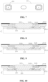
Classifications
-
- H—ELECTRICITY
- H01—ELECTRIC ELEMENTS
- H01M—PROCESSES OR MEANS, e.g. BATTERIES, FOR THE DIRECT CONVERSION OF CHEMICAL ENERGY INTO ELECTRICAL ENERGY
- H01M50/00—Constructional details or processes of manufacture of the non-active parts of electrochemical cells other than fuel cells, e.g. hybrid cells
- H01M50/10—Primary casings; Jackets or wrappings
- H01M50/147—Lids or covers
- H01M50/148—Lids or covers characterised by their shape
- H01M50/15—Lids or covers characterised by their shape for prismatic or rectangular cells
-
- H—ELECTRICITY
- H01—ELECTRIC ELEMENTS
- H01M—PROCESSES OR MEANS, e.g. BATTERIES, FOR THE DIRECT CONVERSION OF CHEMICAL ENERGY INTO ELECTRICAL ENERGY
- H01M50/00—Constructional details or processes of manufacture of the non-active parts of electrochemical cells other than fuel cells, e.g. hybrid cells
- H01M50/10—Primary casings; Jackets or wrappings
- H01M50/172—Arrangements of electric connectors penetrating the casing
- H01M50/174—Arrangements of electric connectors penetrating the casing adapted for the shape of the cells
- H01M50/176—Arrangements of electric connectors penetrating the casing adapted for the shape of the cells for prismatic or rectangular cells
-
- H—ELECTRICITY
- H01—ELECTRIC ELEMENTS
- H01M—PROCESSES OR MEANS, e.g. BATTERIES, FOR THE DIRECT CONVERSION OF CHEMICAL ENERGY INTO ELECTRICAL ENERGY
- H01M50/00—Constructional details or processes of manufacture of the non-active parts of electrochemical cells other than fuel cells, e.g. hybrid cells
- H01M50/10—Primary casings; Jackets or wrappings
- H01M50/183—Sealing members
- H01M50/186—Sealing members characterised by the disposition of the sealing members
- H01M50/188—Sealing members characterised by the disposition of the sealing members the sealing members being arranged between the lid and terminal
-
- H—ELECTRICITY
- H01—ELECTRIC ELEMENTS
- H01M—PROCESSES OR MEANS, e.g. BATTERIES, FOR THE DIRECT CONVERSION OF CHEMICAL ENERGY INTO ELECTRICAL ENERGY
- H01M50/00—Constructional details or processes of manufacture of the non-active parts of electrochemical cells other than fuel cells, e.g. hybrid cells
- H01M50/50—Current conducting connections for cells or batteries
- H01M50/543—Terminals
- H01M50/552—Terminals characterised by their shape
- H01M50/553—Terminals adapted for prismatic, pouch or rectangular cells
-
- H—ELECTRICITY
- H01—ELECTRIC ELEMENTS
- H01M—PROCESSES OR MEANS, e.g. BATTERIES, FOR THE DIRECT CONVERSION OF CHEMICAL ENERGY INTO ELECTRICAL ENERGY
- H01M50/00—Constructional details or processes of manufacture of the non-active parts of electrochemical cells other than fuel cells, e.g. hybrid cells
- H01M50/50—Current conducting connections for cells or batteries
- H01M50/572—Means for preventing undesired use or discharge
- H01M50/584—Means for preventing undesired use or discharge for preventing incorrect connections inside or outside the batteries
- H01M50/586—Means for preventing undesired use or discharge for preventing incorrect connections inside or outside the batteries inside the batteries, e.g. incorrect connections of electrodes
-
- H—ELECTRICITY
- H01—ELECTRIC ELEMENTS
- H01M—PROCESSES OR MEANS, e.g. BATTERIES, FOR THE DIRECT CONVERSION OF CHEMICAL ENERGY INTO ELECTRICAL ENERGY
- H01M50/00—Constructional details or processes of manufacture of the non-active parts of electrochemical cells other than fuel cells, e.g. hybrid cells
- H01M50/60—Arrangements or processes for filling or topping-up with liquids; Arrangements or processes for draining liquids from casings
- H01M50/609—Arrangements or processes for filling with liquid, e.g. electrolytes
- H01M50/627—Filling ports
- H01M50/636—Closing or sealing filling ports, e.g. using lids
-
- H—ELECTRICITY
- H01—ELECTRIC ELEMENTS
- H01M—PROCESSES OR MEANS, e.g. BATTERIES, FOR THE DIRECT CONVERSION OF CHEMICAL ENERGY INTO ELECTRICAL ENERGY
- H01M50/00—Constructional details or processes of manufacture of the non-active parts of electrochemical cells other than fuel cells, e.g. hybrid cells
- H01M50/20—Mountings; Secondary casings or frames; Racks, modules or packs; Suspension devices; Shock absorbers; Transport or carrying devices; Holders
- H01M50/249—Mountings; Secondary casings or frames; Racks, modules or packs; Suspension devices; Shock absorbers; Transport or carrying devices; Holders specially adapted for aircraft or vehicles, e.g. cars or trains
-
- H—ELECTRICITY
- H01—ELECTRIC ELEMENTS
- H01M—PROCESSES OR MEANS, e.g. BATTERIES, FOR THE DIRECT CONVERSION OF CHEMICAL ENERGY INTO ELECTRICAL ENERGY
- H01M50/00—Constructional details or processes of manufacture of the non-active parts of electrochemical cells other than fuel cells, e.g. hybrid cells
- H01M50/30—Arrangements for facilitating escape of gases
- H01M50/342—Non-re-sealable arrangements
- H01M50/3425—Non-re-sealable arrangements in the form of rupturable membranes or weakened parts, e.g. pierced with the aid of a sharp member
-
- H—ELECTRICITY
- H01—ELECTRIC ELEMENTS
- H01M—PROCESSES OR MEANS, e.g. BATTERIES, FOR THE DIRECT CONVERSION OF CHEMICAL ENERGY INTO ELECTRICAL ENERGY
- H01M50/00—Constructional details or processes of manufacture of the non-active parts of electrochemical cells other than fuel cells, e.g. hybrid cells
- H01M50/50—Current conducting connections for cells or batteries
- H01M50/572—Means for preventing undesired use or discharge
- H01M50/584—Means for preventing undesired use or discharge for preventing incorrect connections inside or outside the batteries
- H01M50/59—Means for preventing undesired use or discharge for preventing incorrect connections inside or outside the batteries characterised by the protection means
- H01M50/593—Spacers; Insulating plates
-
- Y—GENERAL TAGGING OF NEW TECHNOLOGICAL DEVELOPMENTS; GENERAL TAGGING OF CROSS-SECTIONAL TECHNOLOGIES SPANNING OVER SEVERAL SECTIONS OF THE IPC; TECHNICAL SUBJECTS COVERED BY FORMER USPC CROSS-REFERENCE ART COLLECTIONS [XRACs] AND DIGESTS
- Y02—TECHNOLOGIES OR APPLICATIONS FOR MITIGATION OR ADAPTATION AGAINST CLIMATE CHANGE
- Y02E—REDUCTION OF GREENHOUSE GAS [GHG] EMISSIONS, RELATED TO ENERGY GENERATION, TRANSMISSION OR DISTRIBUTION
- Y02E60/00—Enabling technologies; Technologies with a potential or indirect contribution to GHG emissions mitigation
- Y02E60/10—Energy storage using batteries
Definitions
- the present application relates to the field of battery technologies, and particularly relates to a top cover assembly, a battery cell, a battery, and an electrical apparatus.
- the present application provides a top cover assembly, a battery cell, a battery, and an electrical apparatus, which, by improving a spatial structure of the top cover assembly, is capable of helping improve an overall volumetric energy density of a battery after battery cells are assembled into the battery.
- the present application provides a top cover assembly, the top cover assembly including:
- the upper surface of the structural member is flush with the upper surface of the top cover body, which is capable of eliminating the influence of the structural member on the overall thickness of the top cover assembly, and can more effectively utilize the space above the upper surface of the structural member, thereby improving the space utilization rate.
- the spatial structure of the top cover assembly it is capable of helping improve the utilization efficiency of the external space after the battery cells are assembled into a battery, thereby improving the overall volumetric energy density of the battery.
- the space above the upper surface of the structural member can also be better utilized, thereby improving the space utilization.
- an accommodating recess may be formed to further accommodate other external electrical connection structural members, which is beneficial to further assist in improving the utilization efficiency of the external space after the battery cells are assembled into the battery, thereby improving the overall volumetric energy density of the battery.
- the height difference is controlled within a smaller preset range, so that the height of the structural member protruding from the upper surface of the top cover body can be ignored, which is also capable of improving the utilization efficiency of the external space of the battery cells equipped with the top cover assembly after the battery is assembled.
- the utilization rate of the space above the upper surface of the structural member is capable of being improved by improving the spatial structure of the top cover assembly, thereby assisting in improving the overall volumetric energy density of the battery after the battery cells are assembled into the battery.
- an accommodating groove is opened on the top cover body, and the structural member includes a terminal post assembling body, and the terminal post assembling body is accommodated in the accommodating groove; where in a thickness direction of the top cover body, an upper surface of the terminal post assembling body is flush with the upper surface of the top cover body, or the upper surface of the terminal post assembling body is lower than the upper surface of the top cover body, or the upper surface of the terminal post assembling body is higher than the upper surface of the top cover body and a height difference is within a preset range.
- the terminal post assembling body is accommodated in the accommodating groove so that in the thickness direction of the top cover body, the upper surface of the terminal post assembling body is flush with the upper surface of the top cover body or lower than the upper surface of the top cover body, or the height difference of the terminal post assembling body protruding from the upper surface of the top cover body is controlled within a preset range, and therefore, by improving the spatial structure of the top cover assembly, when the top cover assembly, the shell, and the electrode assembly together form a battery cell, the utilization rate of the space above the upper surface of the terminal post assembling body is improved, thereby assisting in improving the overall volumetric energy density of the battery after the battery cells are assembled into the battery.
- the height difference between the upper surface of the terminal post assembling body and the upper surface of the top cover body in the thickness direction of the top cover body is -3 mm to 0 mm.
- the height difference between the upper surface of the terminal post assembling body and the upper surface of the top cover body is set to -3 mm to 0 mm, so that the terminal post assembling body is capable of sinking smoothly into the top cover body without occupying too much space inside the top cover body.
- the height difference between the upper surface of the terminal post assembling body and the upper surface of the top cover body in the thickness direction of the top cover body is -2 mm to 0 mm.
- the height difference between the upper surface of the terminal post assembling body and the upper surface of the top cover body is set to -2 mm to 0 mm. Even if the upper surface of the terminal post assembling body is lower than the upper surface of the top cover body or is flush with the upper surface of the top cover body, the terminal post assembling body is capable of smoothly sinking into the top cover assembly.
- the top cover assembly, the shell, and the electrode assembly together form a battery cell, the space above the upper surface of the terminal post assembling body can be better utilized, thereby improving space utilization.
- the upper surface of the terminal post assembling body is lower than the upper surface of the top cover body to form an accommodating recess for accommodating other external electrical connection structural members, which is conducive to further assisting in improving the utilization efficiency of the external space after the battery cells are assembled into the battery, thereby improving the overall volumetric energy density of the battery.
- the terminal post assembling body includes:
- the terminal post assembling body is capable of being safely and stably arranged on the top cover body, and on the other hand, the space above the upper surface of the terminal post assembling body is capable of being more effectively utilized, thereby improving the space utilization rate, which is beneficial to assist in improving the utilization efficiency of the external space after the battery cells are assembled into the battery, thereby improving the overall volumetric energy density of the battery.
- the connecting ring is connected to the groove inner wall of the accommodating groove by welding.
- the connecting ring and the groove inner wall of the accommodating groove are welded to form an integrated structure, so that the arrangement of the terminal post assembling body in the accommodating groove is more stable.
- the top cover body includes a top cover plate and a second insulating member stacked in its own thickness direction, an accommodating groove is opened on the top cover plate, and a first through hole is opened on a groove bottom wall of the accommodating groove; a second through hole in communication with the first through hole is opened on the second insulating member, and when the terminal post body is accommodated in the accommodating groove, one end of the terminal post body sequentially passes through the first through hole and the second through hole.
- the second insulating member is capable of isolating the electrical connection components in the shell from the top cover plate, thereby reducing the short circuit risk of the battery cell.
- the top cover assembly further includes an adapter plate, the adapter plate is arranged on a side of the second insulating member away from the top cover plate, and the adapter plate is configured to connect the terminal post body and the electrode assembly.
- the terminal post body is capable of being stably connected to the electrode assembly in the shell of the battery cell. Therefore, in charging and discharging processes of the battery cell, a positive electrode active material and a negative electrode active material react with an electrolyte solution, thereby forming a stable current loop between the electrode assembly and the terminal post body.
- the thickness of the adapter plate is the same everywhere.
- the structural setting of the above adapter plate is not only capable of achieving a stable connection between the electrode assembly and the terminal post body, but also capable of reducing the space occupied by the adapter plate inside the battery cell, thereby improving the space utilization inside the battery cell.
- the top cover assembly further includes a first sealing member, and the first sealing member is arranged between the terminal post assembling body and the second insulating member in the thickness direction of the top cover body.
- the first sealing member is filled in a gap between the terminal post assembling body and the second insulating member.
- the first sealing member is capable of improving the sealing performance inside the shell, so that the electrode assembly is capable of being more safely sealed in the shell.
- the first sealing member is filled between the terminal post assembling body and the second insulating member in the thickness direction of the top cover body, thereby providing stable support for the terminal post assembling body in the thickness direction of the top cover body and improving the stability of the terminal post assembling body on the top cover body.
- the first sealing member is an elastic sealing member.
- the first sealing member when the first sealing member is elastic, the first sealing member can be interference-fitted between the terminal post assembling body and the second insulating member, thereby improving the sealing performance between the terminal post assembling body and the second insulating member.
- an exhaust vent is further opened on the top cover body, and the structural member further includes a pressure relief member, and the pressure relief member is sealed in the exhaust vent; where in the thickness direction of the top cover body, an upper surface of the pressure relief member is flush with the upper surface of the top cover body, or the upper surface of the pressure relief member is lower than the upper surface of the top cover body, or the upper surface of the pressure relief member is higher than the upper surface of the top cover body and a height difference is within a preset range.
- the pressure relief member when the top cover assembly, the shell, and the electrode assembly together form a battery cell, the pressure relief member can achieve pressure relief inside the battery cell when thermal runaway occurs inside the battery cell, thereby avoiding explosion of the battery cell.
- the pressure relief member is accommodated in the exhaust vent so that in the thickness direction of the top cover body, the upper surface of the pressure relief member is flush with the upper surface of the top cover body or lower than the upper surface of the top cover body, or the height difference of the pressure relief member protruding from the upper surface of the top cover body is controlled within a preset range, and therefore, the space saved above the upper surface of the pressure relief member is capable of being more effectively utilized, thereby improving the space utilization, which is conducive to assisting in improving the utilization efficiency of the external space after the battery cells are assembled into the battery, thereby improving the overall volumetric energy density of the battery.
- a liquid injection hole is further opened on the top cover body, the structural member further includes a second sealing member, and the second sealing member is sealed in the liquid injection hole; where in the thickness direction of the top cover body, an upper surface of the second sealing member is flush with the upper surface of the top cover body, or the upper surface of the second sealing member is lower than the upper surface of the top cover body, or the upper surface of the second sealing member is higher than the upper surface of the top cover body and a height difference is within a preset range.
- liquid can be injected into the battery cell through the liquid injection hole, and the liquid injection hole is sealed by the second sealing member to ensure the normal operation of the battery cell.
- the second sealing member is completely accommodated in the liquid injection hole so that in the thickness direction of the top cover body, the upper surface of the second sealing member is flush with the upper surface of the top cover body or lower than the upper surface of the top cover body, or the height difference of the second sealing member protruding from the upper surface of the top cover body is controlled within a preset range, and therefore, the space saved above the upper surface of the second sealing member is capable of being more effectively utilized, thereby improving the space utilization, which is conducive to assisting in improving the utilization efficiency of the external space after the battery cells are assembled into the battery, thereby improving the overall volumetric energy density of the battery.
- the above arrangement can more effectively and comprehensively compress the thicknesses of different positions of the top cover assembly, thereby improving the efficiency of utilizing the external space after the battery cells are assembled into the battery, and improving the overall volumetric energy density of the battery.
- the preset range is 0 mm to 3 mm.
- the preset range is small, and therefore, the height of the structural member protruding from the upper surface of the top cover body is small, and the impact on the overall thickness of the top cover assembly is small, which, to some extent, is capable of reducing the thickness of the top cover assembly at the corresponding position, thereby being conducive to improving the utilization efficiency of the external space after the battery cells are assembled into the battery, and improving the overall volumetric energy density of the battery.
- the preset range is 0 mm to 2 mm.
- the preset range is further narrowed, which is capable of further improving the utilization of the space above the upper surface of the structural member.
- the present application provides a battery cell, including:
- the present application provides a battery, including the above-mentioned battery cell.
- the present application provides an electrical apparatus, including the above-mentioned battery.
- the top cover assembly, the battery cell, the battery, and the electrical apparatus cause the structural member on the top cover body to sink in the thickness direction of the top cover assembly, thereby reducing the thickness of the top cover assembly at the corresponding position. Therefore, when the top cover assembly is arranged at the opening of the shell in a sealed manner to form a battery cell, it is beneficial to improve the utilization efficiency of the external space after the battery cells are assembled into a battery, so as to utilize the saved space to arrange other external structural members, thereby effectively improving the overall volumetric energy density of the battery.
- an embodiment means that a particular feature, structure, or characteristic described in connection with the embodiment can be included in at least one embodiment of the present application.
- the appearance of this phrase in various places in the specification does not necessarily refer to the same embodiment, nor is it a separate or alternative embodiment that is mutually exclusive with other embodiments. It is explicitly and implicitly understood by those skilled in the art that the embodiments described herein may be combined with other embodiments.
- a plurality of refers to two or more (including two).
- multiple groups refers to two or more groups (including two groups), and “multiple pieces” refers to two or more pieces (including two pieces).
- the technical terms “mounting”, “connection”, “connection” and “fixation” should be understood in a broad sense, for example, they can be fixed connection, detachable connection, or integration; or they can be mechanical connection or electrical connection; or they can be direct connection, indirect connection through an intermediate medium, or communication of the interiors of two elements or the relationship of interaction between two elements.
- mounting should be understood in a broad sense, for example, they can be fixed connection, detachable connection, or integration; or they can be mechanical connection or electrical connection; or they can be direct connection, indirect connection through an intermediate medium, or communication of the interiors of two elements or the relationship of interaction between two elements.
- Power batteries are increasingly more widely used.
- Power batteries are not only applied in energy storage power source systems such as water, fire, wind and solar power stations, but also widely applied in electric transport tools, such as electric bicycles, electric motorcycles, and electric vehicles, as well as many fields, such as military equipment and aerospace.
- electric transport tools such as electric bicycles, electric motorcycles, and electric vehicles, as well as many fields, such as military equipment and aerospace.
- military equipment and aerospace As the application fields of power batteries continue to expand, their market demand is also constantly expanding.
- a battery cell In order to meet higher battery usage requirements, it is necessary to continuously improve the space utilization of the battery, thereby increasing the volumetric energy density of the battery.
- a battery cell In a battery structure, a battery cell is the smallest unit that makes up a battery. The magnitude of the volume of the battery cell will affect the quantity of battery cells that can be accommodated in the battery, thereby affecting the volumetric energy density of the battery.
- a terminal post structure on a top cover assembly protrudes from an upper surface of the top cover assembly, and the protruding terminal post structure increases the overall height of the battery cell and reduces the volumetric energy density of the battery cell.
- the top cover assembly is arranged at an opening of the shell in a sealed manner, there is a certain gap between a top end of the electrode assembly and the terminal post structure on the top cover assembly.
- a protrusion needs to be arranged on the adapter plate to prevent the electrode assembly from shaking inside the shell after connection, thereby causing connection failure. Therefore, the arrangement of the protrusions causes the adapter plate to occupy a large space, thereby reducing the space utilization inside the battery cell.
- the inventors have also discovered that for a current battery cell in which the terminal post structure protrudes from the upper surface of the top cover assembly, on the one hand, in the manufacturing process of the battery cell, the terminal post structure protruding from the upper surface of the top cover assembly is prone to risks such as bumps, thereby causing structural damage to the battery cell. Furthermore, when two or more battery cells are brought together, the protruding terminal post structure on one battery cell is more likely to contact with the protruding terminal post structure on another battery cell, thereby causing the risk of short circuit of the terminal post.
- a bus needs to be arranged on the terminal post structure of each battery cell, and the bus needs to be connected to a Flexible Printed Circuit Board (FPC) of a built-in circuit to achieve connection and sampling between the battery cells.
- FPC Flexible Printed Circuit Board
- the flexible printed circuit board is arranged on the upper surface of the top cover assembly.
- aluminum wires or nickel sheets are usually used for connection.
- the terminal post protruding from the upper surface of the top cover assembly makes the aluminum wire easy to bend in the connection process and is relatively long, which reduces the connection and sampling reliability between the battery cells.
- the nickel sheets are used for connection, the nickel sheets are in a tilted state, which can also easily lead to reduced connection and sampling reliability between battery cells.
- the inventors have designed a top cover assembly after in-depth research. By completely accommodating a terminal post assembling body in an accommodating groove, the terminal post assembling body sinks to the interior of the top cover assembly and the battery cell, thereby forming a terminal post-free top cover assembly, and further improving the space utilization inside the battery cell.
- the battery cell disclosed in embodiment of the present application can be used in, but is not limited to, an electrical apparatus such as a vehicle, a ship, or an aircraft.
- An embodiment of the present application provides an electrical apparatus using a battery as a power source.
- the electrical apparatus may be, but is not limited to, a mobile phone, a tablet, a laptop, an electric toy, an electric tool, a battery cart, an electric vehicle, a ship, a spacecraft, and the like.
- the electric toy may include fixed or mobile electric toys, such as game consoles, electric vehicle toys, electric ship toys, and electric airplane toys.
- the spacecraft may include airplanes, rockets, space shuttles, spaceships, etc.
- an electrical apparatus being a vehicle 1000 is taken as an example for the description.
- Fig. 1 is a schematic structural diagram of a vehicle 1000 according to some embodiments of the present application.
- the vehicle 1000 may be a fuel vehicle, a gas vehicle or a new energy vehicle.
- the new energy vehicle may be an all-electric vehicle, a hybrid vehicle, an extended-range vehicle, or the like.
- a battery 100 is arranged in the vehicle 1000.
- the battery 100 may be arranged at the bottom or head or tail of the vehicle 1000.
- the battery 100 may be used as a power supply for the vehicle 1000, for example, the battery 100 may be used as an operating power source for the vehicle 1000.
- the vehicle 1000 may further include a controller 200 and a motor 300.
- the controller 200 is configured to control the battery 100 to supply power to the motor 300, for example, to supply power for starting, navigation and driving of the vehicle 1000.
- the battery 100 not only may serve as an operating power source of the vehicle 1000, but also may serve as a driving power source of the vehicle 1000, thus replacing or partially replacing fuel or natural gas to provide driving power for the vehicle 1000.
- Fig. 2 is an exploded diagram of a battery 100 according to some embodiments of the present application.
- the battery 100 includes a box body 10 and a battery cell 20, the battery cell 20 being accommodated within the box body 10.
- the box body 10 is used to provide an accommodating space for the battery cell 20, and the box body 10 can be of various structures.
- the box body 10 may include a first part 11 and a second part 12, the first part 11 and the second part 12 covering each other, and the first part 11 and the second part 12 together defining the accommodating space for accommodating the battery cell 20.
- the second part 12 may be of a hollow structure with an opening at one end, and the first part 11 may be of a plate-like structure, where the first part 11 covers the opening side of the second part 12 so that the first part 11 and the second part 12 together define the accommodation space.
- the first part 11 and the second part 12 may each be of a hollow structure with an opening at one end, where the opening side of the first part 11 covers the opening side of the second part 12.
- the box body 10 formed by the first part 11 and the second part 12 may be of a variety of shapes, such as a cylinder and a rectangular solid.
- the battery 100 there may be a plurality of battery cells 20, and the plurality of battery cells 20 may be connected in series or in parallel or in parallel-series, where the parallel-series connection means that the plurality of battery cells 20 are connected in both series and parallel.
- the plurality of battery cells 20 may be directly connected together in series or in parallel or in parallel-series, and then the whole composed of the plurality of battery cells 20 may be accommodated in the box body 10.
- the battery 100 may also be in the form of a battery module first formed by the plurality of battery cells 20 being connected in series or in parallel or in parallel-series, then the plurality of battery modules may be connected in series or in parallel or in parallel-series to form a whole, and accommodated in the box body 10.
- the battery 100 may further include other structures, for example, the battery 100 may further include a bus component configured to realize electrical connections between the plurality of battery cells 20.
- Each battery cell 20 may be a secondary battery or a primary battery; or it may be a lithium-sulfur battery, a sodium-ion battery or a magnesium-ion battery, but is not limited thereto.
- the battery cell 20 may be in the shape of a cylinder, a flat body, a cuboid or others.
- Fig. 3 is a schematic exploded structural diagram of a battery cell 20 according to some embodiments of the present application.
- the battery cell 20 refers to the smallest unit constituting a battery.
- the battery cell 20 includes an end cover, a shell 22, an electrode assembly 23, and other functional components.
- the end cover refers to a component that covers the opening of the shell 22 to isolate an internal environment of the battery cell 20 from an external environment.
- the shape of the end cover may be adaptive to the shape of the shell 22 so as to be matched with the shell 22.
- the end cover may be made of a material (such as aluminum alloy) with a certain hardness and strength, and in this way, the end cover is not easily deformed when being subjected to extrusion and collisions, such that the battery cell 20 is capable of having a higher structural strength, and the safety performance can also be improved.
- a functional component such as an electrode terminal can be arranged on the end cover.
- the electrode terminal may be configured to be electrically connected to the electrode assembly 23, for outputting or inputting electric energy of the battery cell 20.
- the end cover may be further provided with a pressure relief mechanism configured to relief an internal pressure when the internal pressure or temperature of the battery cell 20 reaches a threshold.
- the end cover may be made of various materials, such as copper, iron, aluminum, stainless steel, aluminum alloy, and plastic. This is not specially limited in the embodiments of the present application.
- an insulating member may be further arranged on an inner side of the end cover, and the insulating member may be configured to isolate an electrical connection component in the shell 22 from the end cover, thereby reducing the risk of short circuit.
- the insulating member may be made of plastic, rubber, and the like.
- the shell 22 is an assembly configured to match the end cover to form the internal environment of the battery cell 20.
- the formed internal environment may be configured to accommodate the electrode assembly 23, an electrolytic solution, and other components.
- the shell 22 and the end cover may be separate components, an opening may be formed in the shell 22, and the end cover covers the opening to form the internal environment of the battery cell 20.
- the end cover and the shell 22 may also be integrated.
- the end cover and the shell 22 may form a common connection surface before other components enter the shell.
- the shell 22 is covered with the end cover.
- the shell 22 may be of various shapes and sizes, such as a cuboid, a cylinder, and a hexagonal prism.
- the shape of the shell 22 may be determined according to the specific shape and size of the electrode assembly 23.
- the shell 22 may be made of various materials, such as copper, iron, aluminum, stainless steel, aluminum alloy, and plastic. This is not specially limited in the embodiments of the present application.
- the electrode assembly 23 is a component of a battery cell 100 where an electrochemical reaction occurs.
- One or more electrode assemblies 23 may be included within the shell 22.
- the electrode assembly 23 is mainly formed by winding or stacking a positive electrode plate and a negative electrode plate, and a separator is usually arranged between the positive electrode plate and the negative electrode plate.
- the portions, with active materials, of the positive electrode plate and the negative electrode plate constitute a main body part of a battery cell assembly, and the portions, without the active materials, of the positive electrode plate and the negative electrode plate respectively constitute tabs.
- the positive tab and the negative tab may be located at one end of the main body part together or located at two ends of the main body part respectively. In charging and discharging processes of the battery, the positive electrode active material and the negative electrode active material react with the electrolyte solution, and the tabs are connected to the electrode terminals to form a current loop.
- the present application provides a top cover assembly 21.
- the top cover assembly 21 includes a top cover body 211 and a structural member arranged on the top cover body 211.
- an upper surface of the structural member is flush with an upper surface of the top cover body 211, or the upper surface of the structural member is lower than the upper surface of the top cover body 211, or the upper surface of the structural member is higher than the upper surface of the top cover body 211 and a height difference is within a preset range, so that the upper surface of the structural member slightly protrudes from the upper surface of the top cover body 211.
- the thickness direction a of the top cover body 211 refers to a direction parallel to the height of the battery cell 20 when the top cover assembly 211 covers the opening of the shell 22 of the battery cell 20.
- the upper surface of the structural member refers to a plane where the highest point of the structural member on the side away from the shell 22 of the battery cell 20 is located when the top cover assembly 21 covers the opening of the shell 22 of the battery cell 20.
- the upper surface of the top cover body 211 refers to a plane where the highest point of the top cover body 211 on the side away from the shell 22 of the battery cell 20 is located when the top cover assembly 21 covers the opening of the shell 22 of the battery cell 20.
- the surfaces of the sides of the structural member and the top cover body 211 away from the shell 22 of the battery cell 20 are usually set as planes. Therefore, the surface of the side the structural member away from the shell 22 of the battery cell 20 is the upper surface of the structural member. Similarly, the surface of the side of the top cover body 211 away from the shell 22 of the battery cell 20 is the upper surface of the top cover body 211.
- a top cover assembly in the related art in which a structural member protrudes too much from an upper surface of a top cover body 21, in the embodiments of the present application, when the upper surface of the structural member is flush with the upper surface of the top cover body 211, it is capable of eliminating the influence of the structural member on the overall thickness of the top cover assembly 21, and can more effectively utilize the space above the upper surface of the structural member, thereby improving the space utilization rate.
- the spatial structure of the top cover assembly 21 it is capable of helping improve the utilization efficiency of the external space after the battery cells 20 are assembled into a battery, thereby improving the overall volumetric energy density of the battery. As shown in Fig.
- an accommodating recess may be formed to further accommodate other external electrical connection structural members, which is conducive to assisting in improving the utilization efficiency of the external space after the battery cells 20 are assembled into a battery, thereby improving the overall volumetric energy density of the battery.
- the height difference is controlled within a smaller preset range, so that the height of the structural member protruding from the upper surface of the top cover body 211 can be ignored, which is also capable of improving the utilization efficiency of the external space of the battery cell 20 equipped with the top cover assembly 21 after they are assembled into the battery.
- the utilization rate of the space above the upper surface of the structural member is capable of being improved by improving the spatial structure of the top cover assembly 21, thereby assisting in improving the overall volumetric energy density of the battery after the battery cells 20 are assembled into the battery.
- an accommodating groove 2111 is opened on the top cover body 211.
- the structural member includes a terminal post assembling body 212.
- the terminal post assembling body 212 is accommodated in the accommodating groove 2111.
- an upper surface of the terminal post assembling body 212 is flush with the upper surface of the top cover body 211, or the upper surface of the terminal post assembling body 212 is lower than the upper surface of the top cover body 211, or the upper surface of the terminal post assembling body 212 is higher than the upper surface of the top cover body 211 and a height difference is within a preset range.
- one end of the terminal post assembling body 212 is configured to be connected to a busbar, and the other end can be connected to an external conductor or to the terminal post assembling body 212 on the top cover assembly 21 of another adjacent battery cell 20.
- the terminal post assembling body 212 becomes an electrode terminal.
- the terminal post assembling body 212 may include a positive electrode terminal post assembling body and a negative electrode terminal post assembling body, corresponding to the positive electrode and the negative electrode of the battery cell 20 respectively.
- the structures of the positive electrode terminal post assembling body and the negative electrode terminal post assembling body are the same, and therefore, for the convenience of description, the positive electrode terminal post assembling body and the negative electrode terminal post assembling body are collectively referred to as the terminal post assembling body 212 hereinafter. That is, the terminal post assembling body 212 may be a positive electrode terminal post assembling body or a negative electrode terminal post assembling body.
- two accommodating grooves 2111 may be opened on the top cover body 211 to accommodate the positive electrode terminal post assembling body and the negative electrode terminal post assembling body in a one-to-one corresponding manner.
- the inner contour of the accommodating groove 2111 matches the outer contour of the terminal post assembling body 212. Therefore, when the terminal post assembling body 212 is accommodated in the accommodating groove 2111, no gap is generated between the outer edge of the terminal post assembling body 212 and the groove inner wall of the accommodating groove 2111, so that the terminal post assembling body 212 can be more stably accommodated in the accommodating groove 2111.
- the terminal post assembling body 212 is accommodated in the accommodating groove 2111 so that in the thickness direction a of the top cover body 211, the upper surface of the terminal post assembling body 212 is flush with the upper surface of the top cover body 211 or lower than the upper surface of the top cover body 211, or the height difference of the terminal post assembling body 212 protruding from the upper surface of the top cover body 211 is controlled within a preset range, and therefore, by improving the spatial structure of the top cover assembly 21, when the top cover assembly 21, the shell 22, and the electrode assembly 23 together form a battery cell 20, the utilization rate of the space above the upper surface of the terminal post assembling body 212 is improved, thereby assisting in improving the overall volumetric energy density of the battery after the battery cells 20 are assembled into the battery.
- the height difference between the upper surface of the terminal post assembling body 212 and the upper surface of the top cover body 211 in the thickness direction of the top cover body 211 is -3 mm to 0 mm.
- the terminal post assembling body 212 is capable of sinking smoothly into the top cover body 211 without occupying too much space inside the top cover body 211.
- the height difference between the upper surface of the terminal post assembling body 212 and the upper surface of the top cover body 211 in the thickness direction a of the top cover body 211 is -2 mm to 0 mm.
- the height of the terminal post assembling body 212 is lower than the height of the top cover body 211 or is equal to the height of the top cover body 211.
- the terminal post assembling body 212 is capable of smoothly sinking into the top cover assembly 21, and when the top cover assembly 21, the shell 22, and the electrode assembly 23 together form the battery cell 20, the space above the upper surface of the terminal post assembling body 212 can be better utilized, thereby improving the space utilization.
- the upper surface of the terminal post assembling body 212 is lower than the upper surface of the top cover body 211, so as to form an accommodating recess for accommodating other external electrical connection structural members, which is conducive to further assisting in improving the utilization efficiency of the external space after the battery cells 20 are assembled into a battery, thereby improving the overall volumetric energy density of the battery.
- the height difference range between the upper surface of the terminal post assembling body 212 and the upper surface of the top cover body 211 is a preferred example.
- the height difference between the upper surface of the terminal post assembling body 212 and the upper surface of the top cover body 211 can be selected according to actual conditions, which may not be repeated here.
- the terminal post assembling body 212 includes a terminal post body 2121, a first insulating member 2122, and a connecting ring 2123.
- the first insulating member 2122 is arranged surrounding the outer periphery of the terminal post body 2121.
- the connecting ring 2123 is arranged surrounding the outer periphery of the first insulating member 2122 and connected between the first insulating member 2122 and a groove inner wall of the accommodating groove 2111.
- the terminal post body 2121 refers to a component having one end connected to the busbar and the other end connected to an external conductor or a terminal post assembling body 212 on a top cover assembly 21 in an adjacent battery cell.
- the first insulating member 2122 and the connecting ring 2123 are sequentially arranged surrounding the outer periphery of the terminal post body 2121.
- the connecting ring 2123 is connected to the groove inner wall of the accommodating groove 2111.
- the terminal post assembling body 212 and the top cover body 211 are stably connected to form an integral structure.
- the top cover plate 2112 is usually made of a metal material, that is, the groove inner wall of the accommodating groove 2111 is usually made of a metal material, and therefore, in order to facilitate the connection between the connecting ring 2123 and the groove inner wall of the accommodating groove 2111, the material of the connecting ring 2123 is usually also set to a metal material. Therefore, the first insulating member 2122 is capable of isolating the connecting ring 2123 from the terminal post assembling body 212, thereby reducing the short circuit risk of the battery cell 20.
- the first insulating member 2122 may be made of plastic, rubber, and the like.
- the terminal post assembling body 212 is capable of being safely and stably arranged on the top cover body 211, and on the other hand, the space above the upper surface of the terminal post assembling body 212 is capable of being more effectively utilized, thereby improving the space utilization rate, which is beneficial to assist in improving the utilization efficiency of the external space after the battery cells 20 are assembled into the battery, thereby improving the overall volumetric energy density of the battery.
- the connecting ring 2123 is connected to the groove inner wall of the accommodating groove 2111 by welding.
- the connecting ring 2123 and the groove inner wall 2111 of the accommodating groove are welded to form an integrated structure, so that the arrangement of the terminal post assembling body 212 in the accommodating groove 2111 is more stable.
- the top cover body 211 includes a top cover plate 2112 and a second insulating member 2113 stacked in its thickness direction a, and the accommodating groove 2111 is opened on the top cover plate 2112.
- a first through hole 2114 is opened on a groove bottom wall of the accommodating groove 2111, and a second through hole 2115 in communication with the first through hole 2114 is opened on the second insulating member 2113.
- the top cover plate 2112 may be made of a material with a certain hardness and strength (such as aluminum alloy). Therefore, when the top cover plate 2112 covers the opening of the shell 22 of the battery cell 20, it is capable of protecting the battery cell from deformation when it is squeezed or collided, thereby improving the structural strength of the battery cell.
- the second insulating member 2113 is arranged toward the interior of the shell 22. Therefore, the second insulating member 2113 is capable of isolating the electrical connection components in the shell 22 from the top cover plate 2112, thereby reducing the short circuit risk of the battery cell 20.
- the second insulating member 2113 may be made of plastic, rubber, and the like.
- the accommodating groove 2111 on the top cover plate 2112 is capable of accommodating the terminal post assembling body 212, so that the terminal post assembling body 212 sinks into the inside of the top cover body 211, thereby reducing the overall thickness of the top cover assembly 21.
- the second insulating member 2113 is capable of isolating the electrical connection components in the shell 22 from the top cover plate 2112, thereby reducing the short circuit risk of the battery cell.
- the top cover assembly 21 further includes an adapter plate 213.
- the adapter plate 213 is arranged on the side of the second insulating member 2113 away from the top cover plate 2112.
- the adapter plate 213 is configured to connect the terminal post body 2121 and the electrode assembly.
- the top cover assembly 21 is sealed at the opening of the shell 22.
- the adapter plate 213 is arranged on the side of the second insulating member 2113 away from the top cover plate 2112, that is, the adapter plate 213 is arranged on a side of the second insulating member 2113 facing the interior of the shell 22.
- the adapter plate 213 can be connected between the electrode assembly and the terminal post body 2121 to form a current loop.
- the first through hole 2114 and the second through hole 2115 at least partially overlap, so that the first through hole 2114 is in communication with the second through hole 2115, and one end of the terminal post body 2121 is capable of passing through the first through hole 2114 and the second through hole 2115 in sequence and connecting to the adapter plate 213.
- the terminal post body 2121 is capable of being stably connected to the electrode assembly in the shell 22 of the battery cell 20. Therefore, in charging and discharging processes of the battery cell 20, the positive electrode active material and the negative electrode active material react with the electrolyte solution, thereby forming a stable current loop between the terminal post body 2121 and the electrode assembly.
- the thickness of the adapter plate 213 is the same everywhere. That is, the adapter plate 213 has a first surface and a second surface in its thickness direction a. The first surface and the second surface are parallel to each other, and the distance is equal everywhere between the first surface and the second surface.
- the terminal post assembling body 212 is arranged to sink into the top cover assembly 21 in the present application, and therefore, when the top cover assembly 21 is sealed at the opening of the shell 22, the distance between the top of the electrode assembly inside the shell 22 and the bottom of the terminal post body 2121 is small. Therefore, there is no need to arrange a protruding structure on the adapter plate 213, and a stable connection between the electrode assembly and the terminal post body 2121 is also capable of being achieved.
- the structural setting of the above adapter plate 213 is not only capable of achieving a stable connection between the electrode assembly and the terminal post body 2121, but also capable of reducing the space occupied by the adapter plate 213 inside the battery cell 20, thereby improving the space utilization inside the battery cell 20.
- the top cover assembly 21 further includes a first sealing member 214, and the first sealing member 214 is arranged between the terminal post assembling body 212 and the second insulating member 2113 in the thickness direction a of the top cover body 211.
- the first sealing member 214 is filled in a gap between the terminal post assembling body 212 and the second insulating member 2113.
- the first sealing member 214 is capable of improving the sealing performance inside the shell 22, so that the electrode assembly is capable of being more safely sealed in the shell 22.
- the first sealing member 214 is filled between the terminal post assembling body 212 and the second insulating member 2113 in the thickness direction a of the top cover body 211, thereby providing stable support for the terminal post assembling body 212 in the thickness direction a of the top cover body 211 and improving the stability of the terminal post assembling body 212 on the top cover body 211.
- the first sealing member 214 may be configured as a sealing ring, which is arranged between the terminal post assembling body 212 and the second insulating member 2113 in a surrounding manner.
- the first sealing member 214 is an elastic sealing member.
- the first sealing member 214 When the first sealing member 214 is elastic, the first sealing member 214 can be interference-fitted between the terminal post assembling body 212 and the second insulating member 2113, thereby improving the sealing performance between the terminal post assembling body 212 and the second insulating member 2113.
- the first sealing member 214 may be configured as a structure made of silicone or other elastic materials.
- an exhaust vent 2116 is further opened on the top cover body 211, and the structural member further includes a pressure relief member 215, and the pressure relief member 215 is sealed in the exhaust vent 2116.
- an upper surface of the pressure relief member 215 is flush with the upper surface of the top cover body 211, or the upper surface of the pressure relief member 215 is lower than the upper surface of the top cover body 211, or the upper surface of the pressure relief member 215 is higher than the upper surface of the top cover body 211 and a height difference is within a preset range.
- the pressure relief member 215 is capable of ensuring the sealing performance inside the battery cell 20.
- the gas inside the battery cell 20 is capable of breaking open the pressure relief member 215, thereby achieving pressure relief.
- the pressure relief member 215 is accommodated in the exhaust vent 2116 so that in the thickness direction a of the top cover body 211, the upper surface of the pressure relief member 215 is flush with the upper surface of the top cover body 211 or lower than the upper surface of the top cover body 211, or the height difference of the pressure relief member 215 protruding from the upper surface of the top cover body 211 is controlled within a preset range to avoid the arrangement of the pressure relief member 215 from affecting the overall height of the top cover assembly 21, and therefore, the space saved above the upper surface of the pressure relief member 215 is capable of being more effectively utilized, thereby improving the space utilization, which is conducive to assisting in improving the utilization efficiency of the external space after the battery cells 20 are assembled into the battery, thereby improving the overall volumetric energy density of the battery.
- a liquid injection hole 2117 is further opened on the top cover body 211, the structural member further includes a second sealing member (not shown in the figure), and the second sealing member is sealed in the liquid injection hole 2117.
- a second sealing member (not shown in the figure)
- the second sealing member is sealed in the liquid injection hole 2117.
- an upper surface of the second sealing member is flush with the upper surface of the top cover body 211, or the upper surface of the second sealing member is lower than the upper surface of the top cover body 211, or the upper surface of the second sealing member is higher than the upper surface of the top cover body 211 and a height difference is within a preset range.
- the liquid injection hole 2117 is opened on the top cover body 211 to facilitate the injection of electrolyte solution into the battery cell 20. After the electrolyte solution is injected, the liquid injection hole 2117 is sealed by the second sealing member to ensure the sealing performance inside the battery cell 20.
- the second sealing member is completely accommodated in the liquid injection hole 2117 so that in the thickness direction a of the top cover body 211, the upper surface of the second sealing member is flush with the upper surface of the top cover body 211 or lower than the upper surface of the top cover body 211, or the height difference of the second sealing member protruding from the upper surface of the top cover body 211 is controlled within a preset range to avoid the arrangement of the second sealing member from affecting the overall thickness of the top cover assembly 21, and therefore, the space saved above the upper surface of the second sealing member is capable of being more effectively utilized, thereby improving the space utilization, which is conducive to assisting in improving the utilization efficiency of the external space after the battery cells 20 are assembled into the battery, thereby improving the overall volumetric energy density of the battery.
- the above arrangement can more effectively and comprehensively compress the thicknesses of different positions of the top cover assembly 21, thereby improving the efficiency of utilizing the external space after the battery cells 20 are assembled into the battery, and improving the overall volumetric energy density of the battery.
- the preset range is 0 mm to 3 mm.
- the structural member arranged on the top cover body 211 such as the terminal post assembling body 212, is usually arranged to protrude from the upper surface of the top cover body 211, and the protruding height is greater than 4 mm.
- the height difference is controlled between 0 mm and 3 mm, which is capable of reducing the space occupied by the structural member and improving the utilization of the space above the upper surface of the structural member.
- the preset range is 0 mm to 2 mm.
- the structural members are all accessories such as the terminal post assembling body and an explosion-proof valve on the top cover body 211.
- All the accessories designed on the top cover body 211 are designed to have upper surfaces lower than or flush with the upper surface of the top cover body 211 or higher than the upper surface of the top cover body 211 by a preset height, so that the upper surfaces of all the accessories slightly protrude from the upper surface of the top cover body 211, which can more comprehensively improve the space utilization.
- the structural member may be only the terminal post assembling body on the top cover body 211, or the explosion-proof valve on the top cover body 211, or the like.
- the present application further provides a battery cell 20, and the battery cell 20 includes a shell 22, the above top cover assembly 21, and an electrode assembly.
- the shell 22 has an opening, and the top cover assembly 21 is arranged at the opening in a sealed manner.
- the electrode assembly is accommodated in the shell 22 and connected to the top cover assembly 21.
- the electrode assembly is placed in the shell 22 from the opening, and then the top cover assembly 21 is arranged at the opening in a sealed manner, and the second insulating member 2113 in the top cover assembly 21 is arranged toward the interior of the shell 22.
- the electrode assembly is capable of being connected to the adapter plate 213 in the top cover assembly 21. That is, one end of the adapter plate 213 is connected to the electrode assembly, and the other end is connected to the terminal post body 2121, so that a current loop is formed between the terminal post body 2121 and the electrode assembly, and the battery cell 20 is capable of being charged and discharged smoothly.
- the top cover assembly 21 When the top cover assembly 21 is applied to the battery cell 20, since the structural member such as the terminal post assembling body 212 on the top cover assembly 21 is arranged inside the top cover body 211 by sinking, the utilization of the space above the upper surface of the structural member is improved. When the top cover assembly 21, the shell 22, and the electrode assembly together form the battery cell 20, the overall height of the battery cell 20 can be reduced by 2 mm to 5 mm.
- the present application further provides a battery 100, including the above battery cell 20.
- the height of the battery cell 20 is reduced by 2 mm to 5 mm, so that the battery cell 20 occupies less space inside the battery 100, thereby improving the space utilization inside the battery 100, and increasing the volumetric energy density of the battery 100 by about 1.5% to 5%.
- the present application further provides an electrical apparatus, including the above battery 100.
- the present application provides a top cover assembly 21, which completely accommodates the terminal post assembling body 212 in the accommodating groove 2111 on the top cover plate 2112, and is fixedly connected to the groove inner wall of the accommodating groove 2111 through the connecting ring 2123 in the terminal post assembling body 212, so that the terminal post assembling body 212 is stably arranged in the accommodating groove 2111.
- the upper surface of the terminal post assembling body 212 is flush with the upper surface of the top cover body 211, or lower than the upper surface of the top cover body 211, or the height of the terminal post assembling body 212 protruding from the upper surface of the top cover body 211 is controlled within 2 mm. Therefore, this is conducive to improving the utilization efficiency of the external space after the battery cells 20 are assembled into a battery, so that other external structural members can be arranged using the saved space, thereby improving the overall volumetric energy density of the battery.
- the terminal post assembling body 212 is arranged inside the top cover body 211 in a sinking manner, when the top cover assembly 21 is arranged at the opening of the shell 22 in a sealed manner, the distance between the terminal post assembling body 212 and the electrode assembly in the shell 22 is reduced. Therefore, when the terminal post assembling body 212 and the electrode assembly are connected via the adapter plate 213, the space occupied by the adapter plate 213 is capable of being reduced, thereby further improving the volumetric energy density of the battery cell 20.
Landscapes
- Chemical & Material Sciences (AREA)
- Chemical Kinetics & Catalysis (AREA)
- Electrochemistry (AREA)
- General Chemical & Material Sciences (AREA)
- Sealing Battery Cases Or Jackets (AREA)
- Battery Mounting, Suspending (AREA)
Abstract
Description
- The present application relates to the field of battery technologies, and particularly relates to a top cover assembly, a battery cell, a battery, and an electrical apparatus.
- With the rapid development of new-energy technologies, batteries have been applied to increasingly more fields. As application fields of batteries continue to expand, people require batteries to have higher volumetric energy density to meet higher usage requirements.
- However, at present, a structure of a battery cell is still not fully saturated, and therefore, after the battery cells are assembled into a battery, the space utilization of the battery is low, thereby resulting in a low overall volumetric energy density of the battery.
- Based on this, the present application provides a top cover assembly, a battery cell, a battery, and an electrical apparatus, which, by improving a spatial structure of the top cover assembly, is capable of helping improve an overall volumetric energy density of a battery after battery cells are assembled into the battery.
- In a first aspect, the present application provides a top cover assembly, the top cover assembly including:
- a top cover body; and
- a structural member arranged on the top cover body;
- where in a thickness direction of the top cover body, an upper surface of the structural member is flush with an upper surface of the top cover body, or the upper surface of the structural member is lower than the upper surface of the top cover body, or the upper surface of the structural member is higher than the upper surface of the top cover body and a height difference is within a preset range.
- Compared with a top cover assembly in the related art in which a structural member protrudes too much from an upper surface of a top cover body, in the technical solution of the embodiment of the present application, the upper surface of the structural member is flush with the upper surface of the top cover body, which is capable of eliminating the influence of the structural member on the overall thickness of the top cover assembly, and can more effectively utilize the space above the upper surface of the structural member, thereby improving the space utilization rate. By improving the spatial structure of the top cover assembly, it is capable of helping improve the utilization efficiency of the external space after the battery cells are assembled into a battery, thereby improving the overall volumetric energy density of the battery. In the case where the upper surface of the structural member and the upper surface of the top cover body are lower than the upper surface of the top cover body, the space above the upper surface of the structural member can also be better utilized, thereby improving the space utilization. In addition, in the case where the upper surface of the structural member is lower than the upper surface of the top cover body, an accommodating recess may be formed to further accommodate other external electrical connection structural members, which is beneficial to further assist in improving the utilization efficiency of the external space after the battery cells are assembled into the battery, thereby improving the overall volumetric energy density of the battery. When the upper surface of the structural member is higher than the upper surface of the top cover body, the height difference is controlled within a smaller preset range, so that the height of the structural member protruding from the upper surface of the top cover body can be ignored, which is also capable of improving the utilization efficiency of the external space of the battery cells equipped with the top cover assembly after the battery is assembled. In summary, in the technical solution of the embodiment of the present application, when the top cover assembly, the shell, and an electrode assembly together constitute a battery cell, the utilization rate of the space above the upper surface of the structural member is capable of being improved by improving the spatial structure of the top cover assembly, thereby assisting in improving the overall volumetric energy density of the battery after the battery cells are assembled into the battery.
- In some embodiments, an accommodating groove is opened on the top cover body, and the structural member includes a terminal post assembling body, and the terminal post assembling body is accommodated in the accommodating groove;
where in a thickness direction of the top cover body, an upper surface of the terminal post assembling body is flush with the upper surface of the top cover body, or the upper surface of the terminal post assembling body is lower than the upper surface of the top cover body, or the upper surface of the terminal post assembling body is higher than the upper surface of the top cover body and a height difference is within a preset range. - In the technical solution of the embodiment of the present application, the terminal post assembling body is accommodated in the accommodating groove so that in the thickness direction of the top cover body, the upper surface of the terminal post assembling body is flush with the upper surface of the top cover body or lower than the upper surface of the top cover body, or the height difference of the terminal post assembling body protruding from the upper surface of the top cover body is controlled within a preset range, and therefore, by improving the spatial structure of the top cover assembly, when the top cover assembly, the shell, and the electrode assembly together form a battery cell, the utilization rate of the space above the upper surface of the terminal post assembling body is improved, thereby assisting in improving the overall volumetric energy density of the battery after the battery cells are assembled into the battery.
- In some embodiments, when the upper surface of the terminal post assembling body is flush with the upper surface of the top cover body or lower than the upper surface of the top cover body, the height difference between the upper surface of the terminal post assembling body and the upper surface of the top cover body in the thickness direction of the top cover body is -3 mm to 0 mm.
- In the technical solution of the embodiment of the present application, the height difference between the upper surface of the terminal post assembling body and the upper surface of the top cover body is set to -3 mm to 0 mm, so that the terminal post assembling body is capable of sinking smoothly into the top cover body without occupying too much space inside the top cover body.
- In some embodiments, the height difference between the upper surface of the terminal post assembling body and the upper surface of the top cover body in the thickness direction of the top cover body is -2 mm to 0 mm.
- In the technical solution of the embodiment of the present application, the height difference between the upper surface of the terminal post assembling body and the upper surface of the top cover body is set to -2 mm to 0 mm. Even if the upper surface of the terminal post assembling body is lower than the upper surface of the top cover body or is flush with the upper surface of the top cover body, the terminal post assembling body is capable of smoothly sinking into the top cover assembly. When the top cover assembly, the shell, and the electrode assembly together form a battery cell, the space above the upper surface of the terminal post assembling body can be better utilized, thereby improving space utilization. Moreover, the upper surface of the terminal post assembling body is lower than the upper surface of the top cover body to form an accommodating recess for accommodating other external electrical connection structural members, which is conducive to further assisting in improving the utilization efficiency of the external space after the battery cells are assembled into the battery, thereby improving the overall volumetric energy density of the battery.
- In some embodiments, the terminal post assembling body includes:
- a terminal post body;
- a first insulating member, the first insulating member surrounding the outer periphery of the terminal post body; and
- a connecting ring, the connecting ring surrounding the outer periphery of the first insulating member and connected between the first insulating member and a groove inner wall of the accommodating groove.
- In the technical solution of the embodiment of the present application, through the structural coordination between the terminal post body, the first insulating member, and the connecting ring, on the one hand, the terminal post assembling body is capable of being safely and stably arranged on the top cover body, and on the other hand, the space above the upper surface of the terminal post assembling body is capable of being more effectively utilized, thereby improving the space utilization rate, which is beneficial to assist in improving the utilization efficiency of the external space after the battery cells are assembled into the battery, thereby improving the overall volumetric energy density of the battery.
- In some embodiments, the connecting ring is connected to the groove inner wall of the accommodating groove by welding.
- In the technical solution of the embodiment of the present application, the connecting ring and the groove inner wall of the accommodating groove are welded to form an integrated structure, so that the arrangement of the terminal post assembling body in the accommodating groove is more stable.
- In some embodiments, the top cover body includes a top cover plate and a second insulating member stacked in its own thickness direction, an accommodating groove is opened on the top cover plate, and a first through hole is opened on a groove bottom wall of the accommodating groove; a second through hole in communication with the first through hole is opened on the second insulating member, and when the terminal post body is accommodated in the accommodating groove, one end of the terminal post body sequentially passes through the first through hole and the second through hole.
- In the technical solution of the embodiment of the present application, when the top cover assembly, the shell, and the electrode assembly together form a battery cell, the second insulating member is capable of isolating the electrical connection components in the shell from the top cover plate, thereby reducing the short circuit risk of the battery cell.
- In some embodiments, the top cover assembly further includes an adapter plate, the adapter plate is arranged on a side of the second insulating member away from the top cover plate, and the adapter plate is configured to connect the terminal post body and the electrode assembly.
- In the technical solution of the embodiment of the present application, by providing the adapter plate, the terminal post body is capable of being stably connected to the electrode assembly in the shell of the battery cell. Therefore, in charging and discharging processes of the battery cell, a positive electrode active material and a negative electrode active material react with an electrolyte solution, thereby forming a stable current loop between the electrode assembly and the terminal post body.
- In some embodiments, the thickness of the adapter plate is the same everywhere.
- In the technical solution of the embodiment of the present application, the structural setting of the above adapter plate is not only capable of achieving a stable connection between the electrode assembly and the terminal post body, but also capable of reducing the space occupied by the adapter plate inside the battery cell, thereby improving the space utilization inside the battery cell.
- In some embodiments, the top cover assembly further includes a first sealing member, and the first sealing member is arranged between the terminal post assembling body and the second insulating member in the thickness direction of the top cover body.
- In the technical solution of the embodiment of the present application, on the one hand, the first sealing member is filled in a gap between the terminal post assembling body and the second insulating member. When the top cover assembly covers the opening of the shell of the battery cell, the first sealing member is capable of improving the sealing performance inside the shell, so that the electrode assembly is capable of being more safely sealed in the shell. On the other hand, the first sealing member is filled between the terminal post assembling body and the second insulating member in the thickness direction of the top cover body, thereby providing stable support for the terminal post assembling body in the thickness direction of the top cover body and improving the stability of the terminal post assembling body on the top cover body.
- In some examples, the first sealing member is an elastic sealing member.
- In the technical solution of the embodiment of the present application, when the first sealing member is elastic, the first sealing member can be interference-fitted between the terminal post assembling body and the second insulating member, thereby improving the sealing performance between the terminal post assembling body and the second insulating member.
- In some embodiments, an exhaust vent is further opened on the top cover body, and the structural member further includes a pressure relief member, and the pressure relief member is sealed in the exhaust vent;
where in the thickness direction of the top cover body, an upper surface of the pressure relief member is flush with the upper surface of the top cover body, or the upper surface of the pressure relief member is lower than the upper surface of the top cover body, or the upper surface of the pressure relief member is higher than the upper surface of the top cover body and a height difference is within a preset range. - In the technical solution of the embodiment of the present application, when the top cover assembly, the shell, and the electrode assembly together form a battery cell, the pressure relief member can achieve pressure relief inside the battery cell when thermal runaway occurs inside the battery cell, thereby avoiding explosion of the battery cell. The pressure relief member is accommodated in the exhaust vent so that in the thickness direction of the top cover body, the upper surface of the pressure relief member is flush with the upper surface of the top cover body or lower than the upper surface of the top cover body, or the height difference of the pressure relief member protruding from the upper surface of the top cover body is controlled within a preset range, and therefore, the space saved above the upper surface of the pressure relief member is capable of being more effectively utilized, thereby improving the space utilization, which is conducive to assisting in improving the utilization efficiency of the external space after the battery cells are assembled into the battery, thereby improving the overall volumetric energy density of the battery.
- In some embodiments, a liquid injection hole is further opened on the top cover body, the structural member further includes a second sealing member, and the second sealing member is sealed in the liquid injection hole;
where in the thickness direction of the top cover body, an upper surface of the second sealing member is flush with the upper surface of the top cover body, or the upper surface of the second sealing member is lower than the upper surface of the top cover body, or the upper surface of the second sealing member is higher than the upper surface of the top cover body and a height difference is within a preset range. - In the technical solution of the embodiment of the present application, when the top cover assembly, the shell, and the electrode assembly together form a battery cell, liquid can be injected into the battery cell through the liquid injection hole, and the liquid injection hole is sealed by the second sealing member to ensure the normal operation of the battery cell. Therefore, the second sealing member is completely accommodated in the liquid injection hole so that in the thickness direction of the top cover body, the upper surface of the second sealing member is flush with the upper surface of the top cover body or lower than the upper surface of the top cover body, or the height difference of the second sealing member protruding from the upper surface of the top cover body is controlled within a preset range, and therefore, the space saved above the upper surface of the second sealing member is capable of being more effectively utilized, thereby improving the space utilization, which is conducive to assisting in improving the utilization efficiency of the external space after the battery cells are assembled into the battery, thereby improving the overall volumetric energy density of the battery. As for the top cover assembly that is simultaneously provided with a terminal post assembling body, a pressure relief member, and a second sealing member, the above arrangement can more effectively and comprehensively compress the thicknesses of different positions of the top cover assembly, thereby improving the efficiency of utilizing the external space after the battery cells are assembled into the battery, and improving the overall volumetric energy density of the battery.
- In some embodiments, the preset range is 0 mm to 3 mm.
- In the technical solution of the embodiment of the present application, the preset range is small, and therefore, the height of the structural member protruding from the upper surface of the top cover body is small, and the impact on the overall thickness of the top cover assembly is small, which, to some extent, is capable of reducing the thickness of the top cover assembly at the corresponding position, thereby being conducive to improving the utilization efficiency of the external space after the battery cells are assembled into the battery, and improving the overall volumetric energy density of the battery.
- In some embodiments, the preset range is 0 mm to 2 mm.
- In the technical solution of the embodiment of the present application, the preset range is further narrowed, which is capable of further improving the utilization of the space above the upper surface of the structural member.
- In a second aspect, the present application provides a battery cell, including:
- a shell having an opening;
- the above-mentioned top cover assembly arranged at the opening in a sealed manner; and
- an electrode assembly accommodated in the shell and connected to the top cover assembly.
- In a third aspect, the present application provides a battery, including the above-mentioned battery cell.
- In a fourth aspect, the present application provides an electrical apparatus, including the above-mentioned battery.
- The top cover assembly, the battery cell, the battery, and the electrical apparatus cause the structural member on the top cover body to sink in the thickness direction of the top cover assembly, thereby reducing the thickness of the top cover assembly at the corresponding position. Therefore, when the top cover assembly is arranged at the opening of the shell in a sealed manner to form a battery cell, it is beneficial to improve the utilization efficiency of the external space after the battery cells are assembled into a battery, so as to utilize the saved space to arrange other external structural members, thereby effectively improving the overall volumetric energy density of the battery.
- The above illustrations are merely brief descriptions for the technical solutions of the present application. Specific implementation manners of the present application are described specifically in the following to understand the technical solutions of the present application more clearly and implement the present application according to content of the specification, and to make the above and other objectives, features and advantages of the present application more comprehensible.
- Various other advantages and benefits will become apparent to those of ordinary skill in the art upon reading the following detailed description of the implementations. The drawings are for the purpose of illustrating the preferred implementations only and are not to be considered a limitation to the present application. Furthermore, in all the drawings, the same reference numerals represent the same components. In the drawings:
-
Fig. 1 is a schematic structural diagram of a vehicle according to an embodiment of the present application; -
Fig. 2 is a schematic exploded structural diagram of a battery according to an embodiment of the present application; -
Fig. 3 is a schematic exploded structural diagram of a battery cell according to an embodiment of the present application; -
Fig. 4 is a schematic diagram of an overall structure of a battery cell according to an embodiment of the present application; -
Fig. 5 is a front view of a battery cell according to an embodiment of the present application; -
Fig. 6 is a schematic exploded structural diagram of a top cover assembly according to an embodiment of the present application; -
Fig. 7 is a schematic planar diagram of a top cover assembly according to an embodiment of the present application; -
Fig. 8 is a schematic sectional diagram of a top cover assembly according to an embodiment of the present application; -
Fig. 9 is a schematic sectional diagram of a top cover assembly according to another embodiment of the present application; and -
Fig. 10 is a schematic sectional diagram of a top cover assembly according to another embodiment of the present application. - Description of reference numerals: 1000. Vehicle; 100. Battery; 200. Controller; 300. Motor; 10. Box body; 20. Battery cell; 11. First part; 12. Second part; 21. Top cover assembly; 22. Shell; 23. Electrode assembly; 211. Top cover body; 212. Terminal post assembling body; 213. Adapter plate; 214. First sealing member; 215. Pressure relief member; 2111. Accommodating groove; 2112. Top cover plate; 2113. Second insulating member; 2114. First through hole; 2115. Second through hole; 2116. Exhaust vent; 2117. Liquid injection hole; 2121. Terminal post body; 2122. First insulating member; 2123. Connecting ring; a. Thickness direction.
- Embodiments of the technical solutions of the present application will be described in detail below with reference to the accompanying drawings. The following embodiments are only used to more clearly illustrate the technical solution of the present application, and therefore are only used as examples and cannot be used to limit the scope of protection of the present application.
- Unless otherwise defined, all technical and scientific terms used herein have the same meanings as those commonly understood by those skilled in the art to which the present application pertains to. the terms used herein are for the purpose of describing specific embodiments only, and are not intended to limit the present application. The terms "including" and "having" and any variations thereof in the description and claims of the present application and the aforementioned description of the drawings are intended to cover non-exclusive inclusion.
- In the description of the embodiments of the present application, the technical terms "first", "second", and the like are used only to distinguish between different objects, and are not to be understood as indicating or implying a relative importance or implicitly specifying the number, particular order, or primary and secondary relation of the technical features indicated. In the description of the embodiments of the present application, the meaning of "a plurality of" is two or more, unless otherwise explicitly and specifically defined.
- Reference herein to "an embodiment" means that a particular feature, structure, or characteristic described in connection with the embodiment can be included in at least one embodiment of the present application. The appearance of this phrase in various places in the specification does not necessarily refer to the same embodiment, nor is it a separate or alternative embodiment that is mutually exclusive with other embodiments. It is explicitly and implicitly understood by those skilled in the art that the embodiments described herein may be combined with other embodiments.
- In the description of the embodiments of the present application, the term "and/or" is simply a description of an association of associated objects, which indicates that there may exist three relationships, for example, A and/or B may represent three situations: A exists alone, both A and B exist, and B exists alone. Moreover, the character "/" herein generally indicates that the context objects are in an "or" relationship.
- In the description of the embodiments of the present application, the term "a plurality of" refers to two or more (including two). Similarly, "multiple groups" refers to two or more groups (including two groups), and "multiple pieces" refers to two or more pieces (including two pieces).
- In the description of the embodiments of the present application, the orientation or positional relationships indicated by the technical terms "center", "longitudinal", "transverse", "length", "width", "thickness", "upper", "lower", "front", "back", "left", "right", "vertical", "horizontal", "top", "bottom", "inner", "outer", "clockwise", "counterclockwise", "axial", "radial", "circumferential", etc. are based on the orientation or positional relationships shown in the accompanying drawings, and are only for convenience of description of the present application and simplification of the description, rather than indicating or implying that the indicated device or element must have a specific orientation, be constructed and operate in a specific orientation, and therefore, cannot be understood as a limitation to the present application.
- In the description of the embodiments of the present application, unless otherwise specified and limited, the technical terms "mounting", "connection", "connection" and "fixation" should be understood in a broad sense, for example, they can be fixed connection, detachable connection, or integration; or they can be mechanical connection or electrical connection; or they can be direct connection, indirect connection through an intermediate medium, or communication of the interiors of two elements or the relationship of interaction between two elements. For those of ordinary skill in the art, the specific meanings of the above terms in the embodiments of the present application can be understood according to specific situations.
- At present, from the perspective of the development of the market situation, power batteries are increasingly more widely used. Power batteries are not only applied in energy storage power source systems such as water, fire, wind and solar power stations, but also widely applied in electric transport tools, such as electric bicycles, electric motorcycles, and electric vehicles, as well as many fields, such as military equipment and aerospace. As the application fields of power batteries continue to expand, their market demand is also constantly expanding.
- In order to meet higher battery usage requirements, it is necessary to continuously improve the space utilization of the battery, thereby increasing the volumetric energy density of the battery. In a battery structure, a battery cell is the smallest unit that makes up a battery. The magnitude of the volume of the battery cell will affect the quantity of battery cells that can be accommodated in the battery, thereby affecting the volumetric energy density of the battery.
- The inventors have noticed that in a current battery cell structure, on the one hand, a terminal post structure on a top cover assembly protrudes from an upper surface of the top cover assembly, and the protruding terminal post structure increases the overall height of the battery cell and reduces the volumetric energy density of the battery cell. On the other hand, when an electrode assembly is accommodated in a shell and the top cover assembly is arranged at an opening of the shell in a sealed manner, there is a certain gap between a top end of the electrode assembly and the terminal post structure on the top cover assembly. When the electrode assembly and the terminal post structure are connected via an adapter plate, in order to improve the connection stability between the two, a protrusion needs to be arranged on the adapter plate to prevent the electrode assembly from shaking inside the shell after connection, thereby causing connection failure. Therefore, the arrangement of the protrusions causes the adapter plate to occupy a large space, thereby reducing the space utilization inside the battery cell.
- In addition, the inventors have also discovered that for a current battery cell in which the terminal post structure protrudes from the upper surface of the top cover assembly, on the one hand, in the manufacturing process of the battery cell, the terminal post structure protruding from the upper surface of the top cover assembly is prone to risks such as bumps, thereby causing structural damage to the battery cell. Furthermore, when two or more battery cells are brought together, the protruding terminal post structure on one battery cell is more likely to contact with the protruding terminal post structure on another battery cell, thereby causing the risk of short circuit of the terminal post.
- On the other hand, when battery cells are assembled into a battery, a bus needs to be arranged on the terminal post structure of each battery cell, and the bus needs to be connected to a Flexible Printed Circuit Board (FPC) of a built-in circuit to achieve connection and sampling between the battery cells. In addition, the flexible printed circuit board is arranged on the upper surface of the top cover assembly.
- Specifically, aluminum wires or nickel sheets are usually used for connection. When the aluminum wires are used for connection, the terminal post protruding from the upper surface of the top cover assembly makes the aluminum wire easy to bend in the connection process and is relatively long, which reduces the connection and sampling reliability between the battery cells. When the nickel sheets are used for connection, the nickel sheets are in a tilted state, which can also easily lead to reduced connection and sampling reliability between battery cells.
- Based on the above considerations, in order to solve the problems of low space utilization and volumetric energy density of the battery cell, the inventors have designed a top cover assembly after in-depth research. By completely accommodating a terminal post assembling body in an accommodating groove, the terminal post assembling body sinks to the interior of the top cover assembly and the battery cell, thereby forming a terminal post-free top cover assembly, and further improving the space utilization inside the battery cell.
- The battery cell disclosed in embodiment of the present application can be used in, but is not limited to, an electrical apparatus such as a vehicle, a ship, or an aircraft.
- An embodiment of the present application provides an electrical apparatus using a battery as a power source. The electrical apparatus may be, but is not limited to, a mobile phone, a tablet, a laptop, an electric toy, an electric tool, a battery cart, an electric vehicle, a ship, a spacecraft, and the like. The electric toy may include fixed or mobile electric toys, such as game consoles, electric vehicle toys, electric ship toys, and electric airplane toys. The spacecraft may include airplanes, rockets, space shuttles, spaceships, etc.
- For the convenience of description in the following embodiments, an electrical apparatus being a
vehicle 1000 according to an embodiment of the present application is taken as an example for the description. - Referring to
Fig. 1, Fig. 1 is a schematic structural diagram of avehicle 1000 according to some embodiments of the present application. Thevehicle 1000 may be a fuel vehicle, a gas vehicle or a new energy vehicle. The new energy vehicle may be an all-electric vehicle, a hybrid vehicle, an extended-range vehicle, or the like. Abattery 100 is arranged in thevehicle 1000. Thebattery 100 may be arranged at the bottom or head or tail of thevehicle 1000. Thebattery 100 may be used as a power supply for thevehicle 1000, for example, thebattery 100 may be used as an operating power source for thevehicle 1000. Thevehicle 1000 may further include acontroller 200 and amotor 300. Thecontroller 200 is configured to control thebattery 100 to supply power to themotor 300, for example, to supply power for starting, navigation and driving of thevehicle 1000. - In some embodiments of the present application, the
battery 100 not only may serve as an operating power source of thevehicle 1000, but also may serve as a driving power source of thevehicle 1000, thus replacing or partially replacing fuel or natural gas to provide driving power for thevehicle 1000. - Referring to
Fig. 2, Fig. 2 is an exploded diagram of abattery 100 according to some embodiments of the present application. Thebattery 100 includes abox body 10 and abattery cell 20, thebattery cell 20 being accommodated within thebox body 10. Thebox body 10 is used to provide an accommodating space for thebattery cell 20, and thebox body 10 can be of various structures. In some embodiments, thebox body 10 may include afirst part 11 and asecond part 12, thefirst part 11 and thesecond part 12 covering each other, and thefirst part 11 and thesecond part 12 together defining the accommodating space for accommodating thebattery cell 20. Thesecond part 12 may be of a hollow structure with an opening at one end, and thefirst part 11 may be of a plate-like structure, where thefirst part 11 covers the opening side of thesecond part 12 so that thefirst part 11 and thesecond part 12 together define the accommodation space. Thefirst part 11 and thesecond part 12 may each be of a hollow structure with an opening at one end, where the opening side of thefirst part 11 covers the opening side of thesecond part 12. Of course, thebox body 10 formed by thefirst part 11 and thesecond part 12 may be of a variety of shapes, such as a cylinder and a rectangular solid. - In the
battery 100, there may be a plurality ofbattery cells 20, and the plurality ofbattery cells 20 may be connected in series or in parallel or in parallel-series, where the parallel-series connection means that the plurality ofbattery cells 20 are connected in both series and parallel. The plurality ofbattery cells 20 may be directly connected together in series or in parallel or in parallel-series, and then the whole composed of the plurality ofbattery cells 20 may be accommodated in thebox body 10. Of course, thebattery 100 may also be in the form of a battery module first formed by the plurality ofbattery cells 20 being connected in series or in parallel or in parallel-series, then the plurality of battery modules may be connected in series or in parallel or in parallel-series to form a whole, and accommodated in thebox body 10. Thebattery 100 may further include other structures, for example, thebattery 100 may further include a bus component configured to realize electrical connections between the plurality ofbattery cells 20. - Each
battery cell 20 may be a secondary battery or a primary battery; or it may be a lithium-sulfur battery, a sodium-ion battery or a magnesium-ion battery, but is not limited thereto. Thebattery cell 20 may be in the shape of a cylinder, a flat body, a cuboid or others. - Referring to
Fig. 3, and Fig. 3 is a schematic exploded structural diagram of abattery cell 20 according to some embodiments of the present application. Thebattery cell 20 refers to the smallest unit constituting a battery. As shown inFig. 3 , thebattery cell 20 includes an end cover, ashell 22, anelectrode assembly 23, and other functional components. - The end cover refers to a component that covers the opening of the
shell 22 to isolate an internal environment of thebattery cell 20 from an external environment. Without limitation, the shape of the end cover may be adaptive to the shape of theshell 22 so as to be matched with theshell 22. Optionally, the end cover may be made of a material (such as aluminum alloy) with a certain hardness and strength, and in this way, the end cover is not easily deformed when being subjected to extrusion and collisions, such that thebattery cell 20 is capable of having a higher structural strength, and the safety performance can also be improved. A functional component such as an electrode terminal can be arranged on the end cover. The electrode terminal may be configured to be electrically connected to theelectrode assembly 23, for outputting or inputting electric energy of thebattery cell 20. In some embodiments, the end cover may be further provided with a pressure relief mechanism configured to relief an internal pressure when the internal pressure or temperature of thebattery cell 20 reaches a threshold. The end cover may be made of various materials, such as copper, iron, aluminum, stainless steel, aluminum alloy, and plastic. This is not specially limited in the embodiments of the present application. In some embodiments, an insulating member may be further arranged on an inner side of the end cover, and the insulating member may be configured to isolate an electrical connection component in theshell 22 from the end cover, thereby reducing the risk of short circuit. For example, the insulating member may be made of plastic, rubber, and the like. - The
shell 22 is an assembly configured to match the end cover to form the internal environment of thebattery cell 20. The formed internal environment may be configured to accommodate theelectrode assembly 23, an electrolytic solution, and other components. Theshell 22 and the end cover may be separate components, an opening may be formed in theshell 22, and the end cover covers the opening to form the internal environment of thebattery cell 20. Without limitation, the end cover and theshell 22 may also be integrated. Specifically, the end cover and theshell 22 may form a common connection surface before other components enter the shell. When the interior of theshell 22 is required to be encapsulated, theshell 22 is covered with the end cover. Theshell 22 may be of various shapes and sizes, such as a cuboid, a cylinder, and a hexagonal prism. Specifically, the shape of theshell 22 may be determined according to the specific shape and size of theelectrode assembly 23. Theshell 22 may be made of various materials, such as copper, iron, aluminum, stainless steel, aluminum alloy, and plastic. This is not specially limited in the embodiments of the present application. - The
electrode assembly 23 is a component of abattery cell 100 where an electrochemical reaction occurs. One ormore electrode assemblies 23 may be included within theshell 22. Theelectrode assembly 23 is mainly formed by winding or stacking a positive electrode plate and a negative electrode plate, and a separator is usually arranged between the positive electrode plate and the negative electrode plate. The portions, with active materials, of the positive electrode plate and the negative electrode plate constitute a main body part of a battery cell assembly, and the portions, without the active materials, of the positive electrode plate and the negative electrode plate respectively constitute tabs. The positive tab and the negative tab may be located at one end of the main body part together or located at two ends of the main body part respectively. In charging and discharging processes of the battery, the positive electrode active material and the negative electrode active material react with the electrolyte solution, and the tabs are connected to the electrode terminals to form a current loop. - According to some embodiments of the present application, reference is made to
Fig. 4 ,Fig. 5, and Fig. 6 . The present application provides atop cover assembly 21. Thetop cover assembly 21 includes atop cover body 211 and a structural member arranged on thetop cover body 211. In a thickness direction a of thetop cover body 211, an upper surface of the structural member is flush with an upper surface of thetop cover body 211, or the upper surface of the structural member is lower than the upper surface of thetop cover body 211, or the upper surface of the structural member is higher than the upper surface of thetop cover body 211 and a height difference is within a preset range, so that the upper surface of the structural member slightly protrudes from the upper surface of thetop cover body 211. - It should be noted that the thickness direction a of the
top cover body 211 refers to a direction parallel to the height of thebattery cell 20 when thetop cover assembly 211 covers the opening of theshell 22 of thebattery cell 20. The upper surface of the structural member refers to a plane where the highest point of the structural member on the side away from theshell 22 of thebattery cell 20 is located when thetop cover assembly 21 covers the opening of theshell 22 of thebattery cell 20. The upper surface of thetop cover body 211 refers to a plane where the highest point of thetop cover body 211 on the side away from theshell 22 of thebattery cell 20 is located when thetop cover assembly 21 covers the opening of theshell 22 of thebattery cell 20. - It is understandable that in actual applications, the surfaces of the sides of the structural member and the
top cover body 211 away from theshell 22 of thebattery cell 20 are usually set as planes. Therefore, the surface of the side the structural member away from theshell 22 of thebattery cell 20 is the upper surface of the structural member. Similarly, the surface of the side of thetop cover body 211 away from theshell 22 of thebattery cell 20 is the upper surface of thetop cover body 211. - Referring to
Fig. 7 and Fig. 8 , compared with a top cover assembly in the related art in which a structural member protrudes too much from an upper surface of atop cover body 21, in the embodiments of the present application, when the upper surface of the structural member is flush with the upper surface of thetop cover body 211, it is capable of eliminating the influence of the structural member on the overall thickness of thetop cover assembly 21, and can more effectively utilize the space above the upper surface of the structural member, thereby improving the space utilization rate. In addition, by improving the spatial structure of thetop cover assembly 21, it is capable of helping improve the utilization efficiency of the external space after thebattery cells 20 are assembled into a battery, thereby improving the overall volumetric energy density of the battery. As shown inFig. 9 , when the upper surface of the structural member is lower than the upper surface of thetop cover body 211, the space above the upper surface of the structural member can also be better utilized, thereby improving the space utilization. In addition, when the upper surface of the structural member is lower than the upper surface of thetop cover body 211, an accommodating recess may be formed to further accommodate other external electrical connection structural members, which is conducive to assisting in improving the utilization efficiency of the external space after thebattery cells 20 are assembled into a battery, thereby improving the overall volumetric energy density of the battery. - As shown in
Fig. 10 , when the upper surface of the structural member is higher than the upper surface of thetop cover body 211, the height difference is controlled within a smaller preset range, so that the height of the structural member protruding from the upper surface of thetop cover body 211 can be ignored, which is also capable of improving the utilization efficiency of the external space of thebattery cell 20 equipped with thetop cover assembly 21 after they are assembled into the battery. In summary, in the embodiments of the present application, when thetop cover assembly 21, theshell 22, and theelectrode assembly 23 together constitute abattery cell 20, the utilization rate of the space above the upper surface of the structural member is capable of being improved by improving the spatial structure of thetop cover assembly 21, thereby assisting in improving the overall volumetric energy density of the battery after thebattery cells 20 are assembled into the battery. - Referring to
Fig. 6 again, according to some embodiments of the present application, anaccommodating groove 2111 is opened on thetop cover body 211. The structural member includes a terminalpost assembling body 212. The terminalpost assembling body 212 is accommodated in theaccommodating groove 2111. In the thickness direction a of thetop cover body 211, an upper surface of the terminalpost assembling body 212 is flush with the upper surface of thetop cover body 211, or the upper surface of the terminalpost assembling body 212 is lower than the upper surface of thetop cover body 211, or the upper surface of the terminalpost assembling body 212 is higher than the upper surface of thetop cover body 211 and a height difference is within a preset range. - It should be noted that one end of the terminal
post assembling body 212 is configured to be connected to a busbar, and the other end can be connected to an external conductor or to the terminalpost assembling body 212 on thetop cover assembly 21 of anotheradjacent battery cell 20. When the other end of the terminalpost assembling body 212 is connected to an external conductor, the terminalpost assembling body 212 becomes an electrode terminal. - It is understandable that, since the
battery cell 20 includes a positive electrode and a negative electrode, the terminalpost assembling body 212 may include a positive electrode terminal post assembling body and a negative electrode terminal post assembling body, corresponding to the positive electrode and the negative electrode of thebattery cell 20 respectively. The structures of the positive electrode terminal post assembling body and the negative electrode terminal post assembling body are the same, and therefore, for the convenience of description, the positive electrode terminal post assembling body and the negative electrode terminal post assembling body are collectively referred to as the terminalpost assembling body 212 hereinafter. That is, the terminalpost assembling body 212 may be a positive electrode terminal post assembling body or a negative electrode terminal post assembling body. - Correspondingly, in order to separately accommodate the positive electrode terminal post assembling body and the negative electrode terminal post assembling body, two
accommodating grooves 2111 may be opened on thetop cover body 211 to accommodate the positive electrode terminal post assembling body and the negative electrode terminal post assembling body in a one-to-one corresponding manner. - Furthermore, in order to allow the terminal
post assembling body 212 to be more stably accommodated in theaccommodating groove 2111, the inner contour of theaccommodating groove 2111 matches the outer contour of the terminalpost assembling body 212. Therefore, when the terminalpost assembling body 212 is accommodated in theaccommodating groove 2111, no gap is generated between the outer edge of the terminalpost assembling body 212 and the groove inner wall of theaccommodating groove 2111, so that the terminalpost assembling body 212 can be more stably accommodated in theaccommodating groove 2111. - Specifically, the terminal
post assembling body 212 is accommodated in theaccommodating groove 2111 so that in the thickness direction a of thetop cover body 211, the upper surface of the terminalpost assembling body 212 is flush with the upper surface of thetop cover body 211 or lower than the upper surface of thetop cover body 211, or the height difference of the terminalpost assembling body 212 protruding from the upper surface of thetop cover body 211 is controlled within a preset range, and therefore, by improving the spatial structure of thetop cover assembly 21, when thetop cover assembly 21, theshell 22, and theelectrode assembly 23 together form abattery cell 20, the utilization rate of the space above the upper surface of the terminalpost assembling body 212 is improved, thereby assisting in improving the overall volumetric energy density of the battery after thebattery cells 20 are assembled into the battery. - According to some embodiments of the present application, when the upper surface of the terminal
post assembling body 212 is flush with the upper surface of thetop cover body 211 or lower than the upper surface of thetop cover body 211, the height difference between the upper surface of the terminalpost assembling body 212 and the upper surface of thetop cover body 211 in the thickness direction of thetop cover body 211 is -3 mm to 0 mm. - Therefore, the terminal
post assembling body 212 is capable of sinking smoothly into thetop cover body 211 without occupying too much space inside thetop cover body 211. - According to some embodiments of the present application, the height difference between the upper surface of the terminal
post assembling body 212 and the upper surface of thetop cover body 211 in the thickness direction a of thetop cover body 211 is -2 mm to 0 mm. - When the height difference between the upper surface of the terminal
post assembling body 212 and the upper surface of thetop cover body 211 is -2 mm to 0 mm, the height of the terminalpost assembling body 212 is lower than the height of thetop cover body 211 or is equal to the height of thetop cover body 211. As a result, the terminalpost assembling body 212 is capable of smoothly sinking into thetop cover assembly 21, and when thetop cover assembly 21, theshell 22, and theelectrode assembly 23 together form thebattery cell 20, the space above the upper surface of the terminalpost assembling body 212 can be better utilized, thereby improving the space utilization. Moreover, the upper surface of the terminalpost assembling body 212 is lower than the upper surface of thetop cover body 211, so as to form an accommodating recess for accommodating other external electrical connection structural members, which is conducive to further assisting in improving the utilization efficiency of the external space after thebattery cells 20 are assembled into a battery, thereby improving the overall volumetric energy density of the battery. - Of course, the height difference range between the upper surface of the terminal
post assembling body 212 and the upper surface of thetop cover body 211 is a preferred example. In actual production, the height difference between the upper surface of the terminalpost assembling body 212 and the upper surface of thetop cover body 211 can be selected according to actual conditions, which may not be repeated here. - According to some embodiments of the present application, the terminal
post assembling body 212 includes aterminal post body 2121, a first insulatingmember 2122, and a connectingring 2123. The first insulatingmember 2122 is arranged surrounding the outer periphery of theterminal post body 2121. The connectingring 2123 is arranged surrounding the outer periphery of the first insulatingmember 2122 and connected between the first insulatingmember 2122 and a groove inner wall of theaccommodating groove 2111. - It should be noted that the
terminal post body 2121 refers to a component having one end connected to the busbar and the other end connected to an external conductor or a terminalpost assembling body 212 on atop cover assembly 21 in an adjacent battery cell. The first insulatingmember 2122 and the connectingring 2123 are sequentially arranged surrounding the outer periphery of theterminal post body 2121. When the terminalpost assembling body 212 is accommodated in theaccommodating groove 2111, the connectingring 2123 is connected to the groove inner wall of theaccommodating groove 2111. As a result, the terminalpost assembling body 212 and thetop cover body 211 are stably connected to form an integral structure. - Specifically, the
top cover plate 2112 is usually made of a metal material, that is, the groove inner wall of theaccommodating groove 2111 is usually made of a metal material, and therefore, in order to facilitate the connection between the connectingring 2123 and the groove inner wall of theaccommodating groove 2111, the material of the connectingring 2123 is usually also set to a metal material. Therefore, the first insulatingmember 2122 is capable of isolating the connectingring 2123 from the terminalpost assembling body 212, thereby reducing the short circuit risk of thebattery cell 20. For example, the first insulatingmember 2122 may be made of plastic, rubber, and the like. - Through the structural coordination between the
terminal post body 2121, the first insulatingmember 2122, and the connectingring 2123, on the one hand, the terminalpost assembling body 212 is capable of being safely and stably arranged on thetop cover body 211, and on the other hand, the space above the upper surface of the terminalpost assembling body 212 is capable of being more effectively utilized, thereby improving the space utilization rate, which is beneficial to assist in improving the utilization efficiency of the external space after thebattery cells 20 are assembled into the battery, thereby improving the overall volumetric energy density of the battery. - According to some embodiments of the present application, the connecting
ring 2123 is connected to the groove inner wall of theaccommodating groove 2111 by welding. The connectingring 2123 and the grooveinner wall 2111 of the accommodating groove are welded to form an integrated structure, so that the arrangement of the terminalpost assembling body 212 in theaccommodating groove 2111 is more stable. - According to some embodiments of the present application, the
top cover body 211 includes atop cover plate 2112 and a second insulatingmember 2113 stacked in its thickness direction a, and theaccommodating groove 2111 is opened on thetop cover plate 2112. A first throughhole 2114 is opened on a groove bottom wall of theaccommodating groove 2111, and a second throughhole 2115 in communication with the first throughhole 2114 is opened on the second insulatingmember 2113. When the terminalpost assembling body 212 is accommodated in theaccommodating groove 2111, one end of theterminal post body 2121 sequentially passes through the first throughhole 2114 and the second throughhole 2115. - It should be noted that the
top cover plate 2112 may be made of a material with a certain hardness and strength (such as aluminum alloy). Therefore, when thetop cover plate 2112 covers the opening of theshell 22 of thebattery cell 20, it is capable of protecting the battery cell from deformation when it is squeezed or collided, thereby improving the structural strength of the battery cell. - When the
top cover assembly 21 is sealed and covered on the opening of theshell 22 of thebattery cell 20, the second insulatingmember 2113 is arranged toward the interior of theshell 22. Therefore, the second insulatingmember 2113 is capable of isolating the electrical connection components in theshell 22 from thetop cover plate 2112, thereby reducing the short circuit risk of thebattery cell 20. For example, the second insulatingmember 2113 may be made of plastic, rubber, and the like. - Specifically, the
accommodating groove 2111 on thetop cover plate 2112 is capable of accommodating the terminalpost assembling body 212, so that the terminalpost assembling body 212 sinks into the inside of thetop cover body 211, thereby reducing the overall thickness of thetop cover assembly 21. In addition, when thetop cover assembly 21 is sealed and covered on the opening of theshell 22 of thebattery cell 20, the second insulatingmember 2113 is capable of isolating the electrical connection components in theshell 22 from thetop cover plate 2112, thereby reducing the short circuit risk of the battery cell. - According to some embodiments of the present application, referring to
Fig. 8, Fig. 9, and Fig. 10 again, thetop cover assembly 21 further includes anadapter plate 213. Theadapter plate 213 is arranged on the side of the second insulatingmember 2113 away from thetop cover plate 2112. Theadapter plate 213 is configured to connect theterminal post body 2121 and the electrode assembly. - Specifically, when the
top cover assembly 21, theshell 22, and theelectrode assembly 23 together form thebattery cell 20, thetop cover assembly 21 is sealed at the opening of theshell 22. Theadapter plate 213 is arranged on the side of the second insulatingmember 2113 away from thetop cover plate 2112, that is, theadapter plate 213 is arranged on a side of the second insulatingmember 2113 facing the interior of theshell 22. Thus, theadapter plate 213 can be connected between the electrode assembly and theterminal post body 2121 to form a current loop. - Furthermore, when the
top cover plate 2112 and the second insulatingmember 2113 are stacked, the first throughhole 2114 and the second throughhole 2115 at least partially overlap, so that the first throughhole 2114 is in communication with the second throughhole 2115, and one end of theterminal post body 2121 is capable of passing through the first throughhole 2114 and the second throughhole 2115 in sequence and connecting to theadapter plate 213. - By arranging the
adapter plate 213, theterminal post body 2121 is capable of being stably connected to the electrode assembly in theshell 22 of thebattery cell 20. Therefore, in charging and discharging processes of thebattery cell 20, the positive electrode active material and the negative electrode active material react with the electrolyte solution, thereby forming a stable current loop between theterminal post body 2121 and the electrode assembly. - According to some embodiments of the present application, the thickness of the
adapter plate 213 is the same everywhere. That is, theadapter plate 213 has a first surface and a second surface in its thickness direction a. The first surface and the second surface are parallel to each other, and the distance is equal everywhere between the first surface and the second surface. - The terminal
post assembling body 212 is arranged to sink into thetop cover assembly 21 in the present application, and therefore, when thetop cover assembly 21 is sealed at the opening of theshell 22, the distance between the top of the electrode assembly inside theshell 22 and the bottom of theterminal post body 2121 is small. Therefore, there is no need to arrange a protruding structure on theadapter plate 213, and a stable connection between the electrode assembly and theterminal post body 2121 is also capable of being achieved. - The structural setting of the
above adapter plate 213 is not only capable of achieving a stable connection between the electrode assembly and theterminal post body 2121, but also capable of reducing the space occupied by theadapter plate 213 inside thebattery cell 20, thereby improving the space utilization inside thebattery cell 20. - According to some embodiments of the present application, the
top cover assembly 21 further includes afirst sealing member 214, and thefirst sealing member 214 is arranged between the terminalpost assembling body 212 and the second insulatingmember 2113 in the thickness direction a of thetop cover body 211. - On the one hand, the
first sealing member 214 is filled in a gap between the terminalpost assembling body 212 and the second insulatingmember 2113. When thetop cover assembly 21 covers the opening of theshell 22 of thebattery cell 20, thefirst sealing member 214 is capable of improving the sealing performance inside theshell 22, so that the electrode assembly is capable of being more safely sealed in theshell 22. - On the other hand, the
first sealing member 214 is filled between the terminalpost assembling body 212 and the second insulatingmember 2113 in the thickness direction a of thetop cover body 211, thereby providing stable support for the terminalpost assembling body 212 in the thickness direction a of thetop cover body 211 and improving the stability of the terminalpost assembling body 212 on thetop cover body 211. - Specifically, in order to further improve the sealing effect of the
first sealing member 214 between the terminalpost assembling body 212 and the second insulatingmember 2113, thefirst sealing member 214 may be configured as a sealing ring, which is arranged between the terminalpost assembling body 212 and the second insulatingmember 2113 in a surrounding manner. - According to some embodiments of the present application, the
first sealing member 214 is an elastic sealing member. - When the
first sealing member 214 is elastic, thefirst sealing member 214 can be interference-fitted between the terminalpost assembling body 212 and the second insulatingmember 2113, thereby improving the sealing performance between the terminalpost assembling body 212 and the second insulatingmember 2113. For example, thefirst sealing member 214 may be configured as a structure made of silicone or other elastic materials. - According to some embodiments of the present application, an
exhaust vent 2116 is further opened on thetop cover body 211, and the structural member further includes apressure relief member 215, and thepressure relief member 215 is sealed in theexhaust vent 2116. In the thickness direction a of thetop cover body 211, an upper surface of thepressure relief member 215 is flush with the upper surface of thetop cover body 211, or the upper surface of thepressure relief member 215 is lower than the upper surface of thetop cover body 211, or the upper surface of thepressure relief member 215 is higher than the upper surface of thetop cover body 211 and a height difference is within a preset range. - It should be noted that when thermal runaway or other chemical reactions occur inside the
battery cell 20 due to excessive temperature, a large amount of gas is generated inside thebattery cell 20, causing the pressure inside thebattery cell 20 to increase extremely rapidly. At this time, if the internal pressure of thebattery cell 20 cannot be discharged in time, thebattery cell 20 may explode. - Based on this, it is necessary to open the
exhaust vent 2116 on thetop cover body 211, and arrange thepressure relief member 215 in theexhaust vent 2116 in a sealed manner. When thebattery cell 20 works normally, thepressure relief member 215 is capable of ensuring the sealing performance inside thebattery cell 20. When the internal pressure of thebattery cell 20 is too high, the gas inside thebattery cell 20 is capable of breaking open thepressure relief member 215, thereby achieving pressure relief. - Through the above structure, the
pressure relief member 215 is accommodated in theexhaust vent 2116 so that in the thickness direction a of thetop cover body 211, the upper surface of thepressure relief member 215 is flush with the upper surface of thetop cover body 211 or lower than the upper surface of thetop cover body 211, or the height difference of thepressure relief member 215 protruding from the upper surface of thetop cover body 211 is controlled within a preset range to avoid the arrangement of thepressure relief member 215 from affecting the overall height of thetop cover assembly 21, and therefore, the space saved above the upper surface of thepressure relief member 215 is capable of being more effectively utilized, thereby improving the space utilization, which is conducive to assisting in improving the utilization efficiency of the external space after thebattery cells 20 are assembled into the battery, thereby improving the overall volumetric energy density of the battery. - According to some embodiments of the present application, a
liquid injection hole 2117 is further opened on thetop cover body 211, the structural member further includes a second sealing member (not shown in the figure), and the second sealing member is sealed in theliquid injection hole 2117. In the thickness direction a of thetop cover body 211, an upper surface of the second sealing member is flush with the upper surface of thetop cover body 211, or the upper surface of the second sealing member is lower than the upper surface of thetop cover body 211, or the upper surface of the second sealing member is higher than the upper surface of thetop cover body 211 and a height difference is within a preset range. - It should be noted that after the
battery cell 20 is assembled, it is usually necessary to inject the electrolyte solution into thebattery cell 20. Therefore, theliquid injection hole 2117 is opened on thetop cover body 211 to facilitate the injection of electrolyte solution into thebattery cell 20. After the electrolyte solution is injected, theliquid injection hole 2117 is sealed by the second sealing member to ensure the sealing performance inside thebattery cell 20. - Through the above structure, the second sealing member is completely accommodated in the
liquid injection hole 2117 so that in the thickness direction a of thetop cover body 211, the upper surface of the second sealing member is flush with the upper surface of thetop cover body 211 or lower than the upper surface of thetop cover body 211, or the height difference of the second sealing member protruding from the upper surface of thetop cover body 211 is controlled within a preset range to avoid the arrangement of the second sealing member from affecting the overall thickness of thetop cover assembly 21, and therefore, the space saved above the upper surface of the second sealing member is capable of being more effectively utilized, thereby improving the space utilization, which is conducive to assisting in improving the utilization efficiency of the external space after thebattery cells 20 are assembled into the battery, thereby improving the overall volumetric energy density of the battery. As for thetop cover assembly 21 that is simultaneously provided with a terminalpost assembling body 212, apressure relief member 215, and a second sealing member, the above arrangement can more effectively and comprehensively compress the thicknesses of different positions of thetop cover assembly 21, thereby improving the efficiency of utilizing the external space after thebattery cells 20 are assembled into the battery, and improving the overall volumetric energy density of the battery. - According to some embodiments of the present application, the preset range is 0 mm to 3 mm.
- It should be noted that, currently, the structural member arranged on the
top cover body 211, such as the terminalpost assembling body 212, is usually arranged to protrude from the upper surface of thetop cover body 211, and the protruding height is greater than 4 mm. - Based on this, in some embodiments of the present application, when the upper surface of the structural member is higher than the upper surface of the
top cover body 211, the height difference is controlled between 0 mm and 3 mm, which is capable of reducing the space occupied by the structural member and improving the utilization of the space above the upper surface of the structural member. - According to some embodiments of the present application, the preset range is 0 mm to 2 mm.
- Further limiting the preset range to within 2 mm can further reduce the space occupied by the structural member, thereby further improving the utilization of the space above the upper surface of the structural member.
- In addition, in some embodiments, the structural members are all accessories such as the terminal post assembling body and an explosion-proof valve on the
top cover body 211. All the accessories designed on thetop cover body 211 are designed to have upper surfaces lower than or flush with the upper surface of thetop cover body 211 or higher than the upper surface of thetop cover body 211 by a preset height, so that the upper surfaces of all the accessories slightly protrude from the upper surface of thetop cover body 211, which can more comprehensively improve the space utilization. It is conceivable that, in some embodiments, the structural member may be only the terminal post assembling body on thetop cover body 211, or the explosion-proof valve on thetop cover body 211, or the like. By making the above improvements to a single terminal post assembling body or a single explosion-proof valve, the utilization of the space above the upper surface of the single terminal post assembling body or the utilization of the space above the explosion-proof valve can be correspondingly improved. - Based on the same concept as the above
top cover assembly 21, the present application further provides abattery cell 20, and thebattery cell 20 includes ashell 22, the abovetop cover assembly 21, and an electrode assembly. Theshell 22 has an opening, and thetop cover assembly 21 is arranged at the opening in a sealed manner. The electrode assembly is accommodated in theshell 22 and connected to thetop cover assembly 21. - Specifically, the electrode assembly is placed in the
shell 22 from the opening, and then thetop cover assembly 21 is arranged at the opening in a sealed manner, and the second insulatingmember 2113 in thetop cover assembly 21 is arranged toward the interior of theshell 22. Thus, the electrode assembly is capable of being connected to theadapter plate 213 in thetop cover assembly 21. That is, one end of theadapter plate 213 is connected to the electrode assembly, and the other end is connected to theterminal post body 2121, so that a current loop is formed between theterminal post body 2121 and the electrode assembly, and thebattery cell 20 is capable of being charged and discharged smoothly. - When the
top cover assembly 21 is applied to thebattery cell 20, since the structural member such as the terminalpost assembling body 212 on thetop cover assembly 21 is arranged inside thetop cover body 211 by sinking, the utilization of the space above the upper surface of the structural member is improved. When thetop cover assembly 21, theshell 22, and the electrode assembly together form thebattery cell 20, the overall height of thebattery cell 20 can be reduced by 2 mm to 5 mm. - Based on the conception the same as that of the
above battery cell 20, the present application further provides abattery 100, including theabove battery cell 20. - The height of the
battery cell 20 is reduced by 2 mm to 5 mm, so that thebattery cell 20 occupies less space inside thebattery 100, thereby improving the space utilization inside thebattery 100, and increasing the volumetric energy density of thebattery 100 by about 1.5% to 5%. - Based on the conception the same as that of the
above battery 100, the present application further provides an electrical apparatus, including theabove battery 100. - According to some embodiments of the present application, the present application provides a
top cover assembly 21, which completely accommodates the terminalpost assembling body 212 in theaccommodating groove 2111 on thetop cover plate 2112, and is fixedly connected to the groove inner wall of theaccommodating groove 2111 through the connectingring 2123 in the terminalpost assembling body 212, so that the terminalpost assembling body 212 is stably arranged in theaccommodating groove 2111. In the thickness direction a of thetop cover body 211, the upper surface of the terminalpost assembling body 212 is flush with the upper surface of thetop cover body 211, or lower than the upper surface of thetop cover body 211, or the height of the terminalpost assembling body 212 protruding from the upper surface of thetop cover body 211 is controlled within 2 mm. Therefore, this is conducive to improving the utilization efficiency of the external space after thebattery cells 20 are assembled into a battery, so that other external structural members can be arranged using the saved space, thereby improving the overall volumetric energy density of the battery. - Furthermore, since the terminal
post assembling body 212 is arranged inside thetop cover body 211 in a sinking manner, when thetop cover assembly 21 is arranged at the opening of theshell 22 in a sealed manner, the distance between the terminalpost assembling body 212 and the electrode assembly in theshell 22 is reduced. Therefore, when the terminalpost assembling body 212 and the electrode assembly are connected via theadapter plate 213, the space occupied by theadapter plate 213 is capable of being reduced, thereby further improving the volumetric energy density of thebattery cell 20. - Finally, it should be noted that, the above embodiments are merely used for describing the technical solution of the present application, instead of limiting the present application. Although the present application is described in detail with reference to the foregoing embodiments, those of ordinary skill in the art should understand that they can still make modifications on the technical solution recorded in the above embodiments, or perform equivalent replacements on all or a part of technical features thereof; these modifications or replacements are not intended to make the essences of the corresponding technical solutions depart from the scope of the technical solutions of the embodiments of the present application, and should all be covered in the scope of the claims and specification of the present application. In particular, the technical features mentioned in the various embodiments can be combined in any manner as long as there is no structural conflict. The present application is not limited to the specific embodiments disclosed herein, but rather includes all technical solutions falling within the scope of the claims.
Claims (18)
- A top cover assembly, the top cover assembly comprising:a top cover body; anda structural member arranged on the top cover body;wherein in a thickness direction of the top cover body, an upper surface of the structural member is flush with an upper surface of the top cover body, or the upper surface of the structural member is lower than the upper surface of the top cover body, or the upper surface of the structural member is higher than the upper surface of the top cover body and a height difference is within a preset range.
- The top cover assembly according to claim 1, wherein an accommodating groove is opened on the top cover body, and the structural member comprises a terminal post assembling body, and the terminal post assembling body is accommodated in the accommodating groove;
wherein in the thickness direction of the top cover body, an upper surface of the terminal post assembling body is flush with the upper surface of the top cover body, or the upper surface of the terminal post assembling body is lower than the upper surface of the top cover body, or the upper surface of the terminal post assembling body is higher than the upper surface of the top cover body and a height difference is within the preset range. - The top cover assembly according to claim 2, wherein when the upper surface of the terminal post assembling body is flush with the upper surface of the top cover body or lower than the upper surface of the top cover body, the height difference between the upper surface of the terminal post assembling body and the upper surface of the top cover body in the thickness direction of the top cover body is -3 mm to 0 mm.
- The top cover assembly according to claim 3, wherein the height difference between the upper surface of the terminal post assembling body and the upper surface of the top cover body in the thickness direction of the top cover body is -2 mm to 0 mm.
- The top cover assembly according to any one of claims 2 to 4, wherein the terminal post assembling body comprises:a terminal post body;a first insulating member, the first insulating member being arranged surrounding the outer periphery of the terminal post body; anda connecting ring, the connecting ring being arranged surrounding the outer periphery of the first insulating member and connected between the first insulating member and a groove inner wall of the accommodating groove.
- The top cover assembly according to claim 5, wherein the connecting ring is connected to the groove inner wall of the accommodating groove by welding.
- The top cover assembly according to claim 5 or 6, wherein the top cover body comprises a top cover plate and a second insulating member stacked in its own thickness direction, the accommodating groove is opened on the top cover plate, and a first through hole is opened on a groove bottom wall of the accommodating groove; a second through hole in communication with the first through hole is opened on the second insulating member, and when the terminal post body is accommodated in the accommodating groove, one end of the terminal post body sequentially passes through the first through hole and the second through hole.
- The top cover assembly according to claim 7, wherein the top cover assembly further comprises an adapter plate, the adapter plate is arranged on a side of the second insulating member away from the top cover plate, and the adapter plate is configured to connect the terminal post body and the electrode assembly.
- The top cover assembly according to claim 8, wherein the thickness of the adapter plate is the same everywhere.
- The top cover assembly according to any one of claim 7 to 9, wherein the top cover assembly further comprises a first sealing member, and the first sealing member is arranged between the terminal post assembling body and the second insulating member in the thickness direction of the top cover body.
- The top cover assembly according to claim 10, wherein the first sealing member is an elastic sealing member.
- The top cover assembly according to any one of claims 1 to 11, wherein an exhaust vent is further opened on the top cover body, and the structural member further comprises a pressure relief member, and the pressure relief member is sealed in the exhaust vent;
wherein in the thickness direction of the top cover body, an upper surface of the pressure relief member is flush with the upper surface of the top cover body, or the upper surface of the pressure relief member is lower than the upper surface of the top cover body, or the upper surface of the pressure relief member is higher than the upper surface of the top cover body and a height difference is within the preset range. - The top cover assembly according to any one of claims 1 to 12, wherein a liquid injection hole is further opened on the top cover body, the structural member further comprises a second sealing member, and the second sealing member is sealed in the liquid injection hole;
wherein in the thickness direction of the top cover body, an upper surface of the second sealing member is flush with the upper surface of the top cover body, or the upper surface of the second sealing member is lower than the upper surface of the top cover body, or the upper surface of the second sealing member is higher than the upper surface of the top cover body and a height difference is within the preset range. - The top cover assembly according to any one of claims 1 to 13, wherein the preset range is 0 mm to 3 mm.
- The top cover assembly according to claim 14, wherein the preset range is 0 mm to 2 mm.
- A battery cell , comprising:a shell having an opening;the top cover assembly according to any one of claims 1 to 15, arranged at the opening in a sealed manner; andan electrode assembly accommodated in the shell and connected to the top cover assembly.
- A battery, comprising the battery cell according to claim 16.
- An electrical apparatus, comprising the battery according to claim 17.
Applications Claiming Priority (1)
| Application Number | Priority Date | Filing Date | Title |
|---|---|---|---|
| PCT/CN2022/114973 WO2024040545A1 (en) | 2022-08-26 | 2022-08-26 | Top cover assembly, battery cell, battery, and electric apparatus |
Publications (2)
| Publication Number | Publication Date |
|---|---|
| EP4560798A1 true EP4560798A1 (en) | 2025-05-28 |
| EP4560798A4 EP4560798A4 (en) | 2025-12-03 |
Family
ID=86283627
Family Applications (1)
| Application Number | Title | Priority Date | Filing Date |
|---|---|---|---|
| EP22956091.7A Pending EP4560798A4 (en) | 2022-08-26 | 2022-08-26 | COVERING ASSEMBLY, BATTERY CELL, BATTERY AND ELECTRICAL DEVICE |
Country Status (3)
| Country | Link |
|---|---|
| EP (1) | EP4560798A4 (en) |
| CN (2) | CN118511369A (en) |
| WO (1) | WO2024040545A1 (en) |
Cited By (1)
| Publication number | Priority date | Publication date | Assignee | Title |
|---|---|---|---|---|
| EP4601087A4 (en) * | 2022-12-30 | 2026-02-25 | Hithium Tech Hk Ltd | COVERING ARRANGEMENT, BATTERY CELL, ASSEMBLY METHOD FOR BATTERY CELL AND ELECTRICAL DEVICE |
Families Citing this family (3)
| Publication number | Priority date | Publication date | Assignee | Title |
|---|---|---|---|---|
| CN220138625U (en) * | 2023-06-27 | 2023-12-05 | 欣旺达动力科技股份有限公司 | Battery packs and electrical devices |
| CN220774554U (en) * | 2024-01-18 | 2024-04-12 | 宁德时代新能源科技股份有限公司 | Battery cover plate, battery unit, battery and electric equipment |
| WO2025245895A1 (en) * | 2024-05-31 | 2025-12-04 | 宁德时代新能源科技股份有限公司 | Battery cell, battery, and electrical apparatus |
Family Cites Families (10)
| Publication number | Priority date | Publication date | Assignee | Title |
|---|---|---|---|---|
| EP3309856B1 (en) * | 2015-06-12 | 2020-12-30 | Kabushiki Kaisha Toshiba | Battery and battery module |
| EP3491683B1 (en) * | 2016-08-01 | 2026-02-18 | CPS Technology Holdings LLC | Overcharge protection systems for prismatic lithium ion battery cells having neutral or non-conductive packaging |
| CN114843668B (en) * | 2017-08-30 | 2023-12-12 | 宁德时代新能源科技股份有限公司 | Top cap subassembly, secondary cell and battery module of secondary cell |
| CN208315621U (en) * | 2018-06-13 | 2019-01-01 | 宁德时代新能源科技股份有限公司 | Cap assembly, battery and the battery modules of battery |
| JP7368080B2 (en) * | 2018-08-31 | 2023-10-24 | 三洋電機株式会社 | secondary battery |
| CN210576041U (en) * | 2019-11-13 | 2020-05-19 | 深圳市科达利实业股份有限公司 | Power battery cover plate and power battery |
| CN216054930U (en) * | 2021-04-06 | 2022-03-15 | 荣盛盟固利新能源科技有限公司 | Battery cover and power battery |
| CN216354472U (en) * | 2021-09-30 | 2022-04-19 | 蜂巢能源科技有限公司 | Power battery top cover |
| CN217086803U (en) * | 2022-03-10 | 2022-07-29 | 浙江中泽精密科技有限公司 | Power battery and power battery assembly |
| CN114865182A (en) * | 2022-04-28 | 2022-08-05 | 深圳市科达利实业股份有限公司 | Battery top cap subassembly and power battery |
-
2022
- 2022-08-26 EP EP22956091.7A patent/EP4560798A4/en active Pending
- 2022-08-26 CN CN202280088050.2A patent/CN118511369A/en active Pending
- 2022-08-26 WO PCT/CN2022/114973 patent/WO2024040545A1/en not_active Ceased
- 2022-10-09 CN CN202222644654.0U patent/CN219040589U/en active Active
Cited By (1)
| Publication number | Priority date | Publication date | Assignee | Title |
|---|---|---|---|---|
| EP4601087A4 (en) * | 2022-12-30 | 2026-02-25 | Hithium Tech Hk Ltd | COVERING ARRANGEMENT, BATTERY CELL, ASSEMBLY METHOD FOR BATTERY CELL AND ELECTRICAL DEVICE |
Also Published As
| Publication number | Publication date |
|---|---|
| CN219040589U (en) | 2023-05-16 |
| CN118511369A (en) | 2024-08-16 |
| WO2024040545A1 (en) | 2024-02-29 |
| EP4560798A4 (en) | 2025-12-03 |
Similar Documents
| Publication | Publication Date | Title |
|---|---|---|
| CN216055080U (en) | Battery cell, battery and power consumption device | |
| US20240304918A1 (en) | Box of battery, battery, electrical apparatus, and manufacturing device for batteries | |
| CN216213726U (en) | Battery cell, battery, electric device, and apparatus for manufacturing battery cell | |
| CN218414803U (en) | Top cover assembly, battery cell, battery and electrical device | |
| CN219040589U (en) | Top cover assembly, battery cell, battery and electrical device | |
| CN217306714U (en) | Battery monomer end cover, battery monomer, battery and power consumption device | |
| EP4425654A1 (en) | Battery cell, battery and electric device | |
| CN217768550U (en) | End cap assemblies for battery cells, battery cells, batteries and electrical equipment | |
| CN218385672U (en) | End cover components, battery cells, batteries and electrical equipment | |
| CN220527157U (en) | Sampling assembly, battery and power utilization device | |
| EP4276994A1 (en) | Battery and electric device | |
| CN218769817U (en) | Battery monomer, battery and consumer | |
| WO2023050245A1 (en) | Adapter component, battery cell, battery, electric device, and method and device for manufacturing battery cell | |
| CN222126920U (en) | Batteries, battery modules, battery packs, energy storage devices and power consumption devices | |
| CN219321545U (en) | Battery and electricity utilization device | |
| CN217740741U (en) | Battery cells, batteries and electrical equipment | |
| CN219610581U (en) | Shell assembly, battery cell, battery and electric equipment | |
| CN216015615U (en) | Adapter part, single battery, power consumption device and single battery manufacturing equipment | |
| CN220963648U (en) | Battery cells, batteries and electrical equipment | |
| CN217934145U (en) | Battery cells, batteries and electrical devices | |
| CN216872135U (en) | Batteries and battery modules, electrical energy equipment | |
| CN115911255B (en) | End cap assembly, battery cell, battery and electrical device | |
| JP7595748B2 (en) | Battery cell, battery, power consumption device, and battery cell manufacturing method and manufacturing equipment | |
| US12537232B2 (en) | Battery cell, battery, electrical apparatus, and manufacturing method for battery cell | |
| CN223427603U (en) | End cover assembly, battery cell, battery device and power utilization device |
Legal Events
| Date | Code | Title | Description |
|---|---|---|---|
| STAA | Information on the status of an ep patent application or granted ep patent |
Free format text: STATUS: THE INTERNATIONAL PUBLICATION HAS BEEN MADE |
|
| PUAI | Public reference made under article 153(3) epc to a published international application that has entered the european phase |
Free format text: ORIGINAL CODE: 0009012 |
|
| STAA | Information on the status of an ep patent application or granted ep patent |
Free format text: STATUS: REQUEST FOR EXAMINATION WAS MADE |
|
| 17P | Request for examination filed |
Effective date: 20250219 |
|
| AK | Designated contracting states |
Kind code of ref document: A1 Designated state(s): AL AT BE BG CH CY CZ DE DK EE ES FI FR GB GR HR HU IE IS IT LI LT LU LV MC MK MT NL NO PL PT RO RS SE SI SK SM TR |
|
| RAP1 | Party data changed (applicant data changed or rights of an application transferred) |
Owner name: CONTEMPORARY AMPEREX TECHNOLOGY(HONG KONG) LIMITED |
|
| A4 | Supplementary search report drawn up and despatched |
Effective date: 20251030 |
|
| DAV | Request for validation of the european patent (deleted) | ||
| DAX | Request for extension of the european patent (deleted) | ||
| RIC1 | Information provided on ipc code assigned before grant |
Ipc: H01M 50/15 20210101AFI20251024BHEP Ipc: H01M 50/176 20210101ALI20251024BHEP |