EP4560795A1 - Battery module, battery pack, and electric device - Google Patents
Battery module, battery pack, and electric device Download PDFInfo
- Publication number
- EP4560795A1 EP4560795A1 EP24214881.5A EP24214881A EP4560795A1 EP 4560795 A1 EP4560795 A1 EP 4560795A1 EP 24214881 A EP24214881 A EP 24214881A EP 4560795 A1 EP4560795 A1 EP 4560795A1
- Authority
- EP
- European Patent Office
- Prior art keywords
- cell
- buffer
- elastic member
- along
- wall
- Prior art date
- Legal status (The legal status is an assumption and is not a legal conclusion. Google has not performed a legal analysis and makes no representation as to the accuracy of the status listed.)
- Pending
Links
Images


Classifications
-
- H—ELECTRICITY
- H01—ELECTRIC ELEMENTS
- H01M—PROCESSES OR MEANS, e.g. BATTERIES, FOR THE DIRECT CONVERSION OF CHEMICAL ENERGY INTO ELECTRICAL ENERGY
- H01M50/00—Constructional details or processes of manufacture of the non-active parts of electrochemical cells other than fuel cells, e.g. hybrid cells
- H01M50/20—Mountings; Secondary casings or frames; Racks, modules or packs; Suspension devices; Shock absorbers; Transport or carrying devices; Holders
- H01M50/233—Mountings; Secondary casings or frames; Racks, modules or packs; Suspension devices; Shock absorbers; Transport or carrying devices; Holders characterised by physical properties of casings or racks, e.g. dimensions
- H01M50/242—Mountings; Secondary casings or frames; Racks, modules or packs; Suspension devices; Shock absorbers; Transport or carrying devices; Holders characterised by physical properties of casings or racks, e.g. dimensions adapted for protecting batteries against vibrations, collision impact or swelling
-
- H—ELECTRICITY
- H01—ELECTRIC ELEMENTS
- H01M—PROCESSES OR MEANS, e.g. BATTERIES, FOR THE DIRECT CONVERSION OF CHEMICAL ENERGY INTO ELECTRICAL ENERGY
- H01M50/00—Constructional details or processes of manufacture of the non-active parts of electrochemical cells other than fuel cells, e.g. hybrid cells
- H01M50/10—Primary casings; Jackets or wrappings
- H01M50/102—Primary casings; Jackets or wrappings characterised by their shape or physical structure
- H01M50/105—Pouches or flexible bags
-
- H—ELECTRICITY
- H01—ELECTRIC ELEMENTS
- H01M—PROCESSES OR MEANS, e.g. BATTERIES, FOR THE DIRECT CONVERSION OF CHEMICAL ENERGY INTO ELECTRICAL ENERGY
- H01M50/00—Constructional details or processes of manufacture of the non-active parts of electrochemical cells other than fuel cells, e.g. hybrid cells
- H01M50/20—Mountings; Secondary casings or frames; Racks, modules or packs; Suspension devices; Shock absorbers; Transport or carrying devices; Holders
- H01M50/204—Racks, modules or packs for multiple batteries or multiple cells
- H01M50/207—Racks, modules or packs for multiple batteries or multiple cells characterised by their shape
- H01M50/211—Racks, modules or packs for multiple batteries or multiple cells characterised by their shape adapted for pouch cells
-
- H—ELECTRICITY
- H01—ELECTRIC ELEMENTS
- H01M—PROCESSES OR MEANS, e.g. BATTERIES, FOR THE DIRECT CONVERSION OF CHEMICAL ENERGY INTO ELECTRICAL ENERGY
- H01M50/00—Constructional details or processes of manufacture of the non-active parts of electrochemical cells other than fuel cells, e.g. hybrid cells
- H01M50/20—Mountings; Secondary casings or frames; Racks, modules or packs; Suspension devices; Shock absorbers; Transport or carrying devices; Holders
- H01M50/233—Mountings; Secondary casings or frames; Racks, modules or packs; Suspension devices; Shock absorbers; Transport or carrying devices; Holders characterised by physical properties of casings or racks, e.g. dimensions
- H01M50/24—Mountings; Secondary casings or frames; Racks, modules or packs; Suspension devices; Shock absorbers; Transport or carrying devices; Holders characterised by physical properties of casings or racks, e.g. dimensions adapted for protecting batteries from their environment, e.g. from corrosion
-
- H—ELECTRICITY
- H01—ELECTRIC ELEMENTS
- H01M—PROCESSES OR MEANS, e.g. BATTERIES, FOR THE DIRECT CONVERSION OF CHEMICAL ENERGY INTO ELECTRICAL ENERGY
- H01M50/00—Constructional details or processes of manufacture of the non-active parts of electrochemical cells other than fuel cells, e.g. hybrid cells
- H01M50/20—Mountings; Secondary casings or frames; Racks, modules or packs; Suspension devices; Shock absorbers; Transport or carrying devices; Holders
- H01M50/244—Secondary casings; Racks; Suspension devices; Carrying devices; Holders characterised by their mounting method
-
- H—ELECTRICITY
- H01—ELECTRIC ELEMENTS
- H01M—PROCESSES OR MEANS, e.g. BATTERIES, FOR THE DIRECT CONVERSION OF CHEMICAL ENERGY INTO ELECTRICAL ENERGY
- H01M50/00—Constructional details or processes of manufacture of the non-active parts of electrochemical cells other than fuel cells, e.g. hybrid cells
- H01M50/20—Mountings; Secondary casings or frames; Racks, modules or packs; Suspension devices; Shock absorbers; Transport or carrying devices; Holders
- H01M50/262—Mountings; Secondary casings or frames; Racks, modules or packs; Suspension devices; Shock absorbers; Transport or carrying devices; Holders with fastening means, e.g. locks
- H01M50/264—Mountings; Secondary casings or frames; Racks, modules or packs; Suspension devices; Shock absorbers; Transport or carrying devices; Holders with fastening means, e.g. locks for cells or batteries, e.g. straps, tie rods or peripheral frames
-
- H—ELECTRICITY
- H01—ELECTRIC ELEMENTS
- H01M—PROCESSES OR MEANS, e.g. BATTERIES, FOR THE DIRECT CONVERSION OF CHEMICAL ENERGY INTO ELECTRICAL ENERGY
- H01M50/00—Constructional details or processes of manufacture of the non-active parts of electrochemical cells other than fuel cells, e.g. hybrid cells
- H01M50/20—Mountings; Secondary casings or frames; Racks, modules or packs; Suspension devices; Shock absorbers; Transport or carrying devices; Holders
- H01M50/271—Lids or covers for the racks or secondary casings
-
- H—ELECTRICITY
- H01—ELECTRIC ELEMENTS
- H01M—PROCESSES OR MEANS, e.g. BATTERIES, FOR THE DIRECT CONVERSION OF CHEMICAL ENERGY INTO ELECTRICAL ENERGY
- H01M50/00—Constructional details or processes of manufacture of the non-active parts of electrochemical cells other than fuel cells, e.g. hybrid cells
- H01M50/10—Primary casings; Jackets or wrappings
- H01M50/102—Primary casings; Jackets or wrappings characterised by their shape or physical structure
- H01M50/103—Primary casings; Jackets or wrappings characterised by their shape or physical structure prismatic or rectangular
-
- H—ELECTRICITY
- H01—ELECTRIC ELEMENTS
- H01M—PROCESSES OR MEANS, e.g. BATTERIES, FOR THE DIRECT CONVERSION OF CHEMICAL ENERGY INTO ELECTRICAL ENERGY
- H01M50/00—Constructional details or processes of manufacture of the non-active parts of electrochemical cells other than fuel cells, e.g. hybrid cells
- H01M50/20—Mountings; Secondary casings or frames; Racks, modules or packs; Suspension devices; Shock absorbers; Transport or carrying devices; Holders
- H01M50/204—Racks, modules or packs for multiple batteries or multiple cells
- H01M50/207—Racks, modules or packs for multiple batteries or multiple cells characterised by their shape
- H01M50/209—Racks, modules or packs for multiple batteries or multiple cells characterised by their shape adapted for prismatic or rectangular cells
-
- Y—GENERAL TAGGING OF NEW TECHNOLOGICAL DEVELOPMENTS; GENERAL TAGGING OF CROSS-SECTIONAL TECHNOLOGIES SPANNING OVER SEVERAL SECTIONS OF THE IPC; TECHNICAL SUBJECTS COVERED BY FORMER USPC CROSS-REFERENCE ART COLLECTIONS [XRACs] AND DIGESTS
- Y02—TECHNOLOGIES OR APPLICATIONS FOR MITIGATION OR ADAPTATION AGAINST CLIMATE CHANGE
- Y02E—REDUCTION OF GREENHOUSE GAS [GHG] EMISSIONS, RELATED TO ENERGY GENERATION, TRANSMISSION OR DISTRIBUTION
- Y02E60/00—Enabling technologies; Technologies with a potential or indirect contribution to GHG emissions mitigation
- Y02E60/10—Energy storage using batteries
Definitions
- This application relates to the field of battery technologies, and in particular, to a battery module, a battery pack, and an electric device.
- Batteries are widely used in portable electronic devices, electric vehicles, electric tools, drones, energy storage devices, and other fields. As the application environments and conditions become more complex, higher requirements are imposed on the reliability of batteries.
- Some embodiments of this application provide a battery module, a battery pack, and an electric device, so as to improve the reliability of batteries.
- the battery module includes a cell assembly, an elastic member, and a buffer, where the cell assembly includes a plurality of cell units stacked along a first direction, and each cell unit includes a cell and a first bracket.
- the cell includes a cell housing, an electrode assembly, and electrode terminals, where the cell housing includes a main body and a first sealing portion, the cell housing includes a main body and a first sealing portion, and the electrode terminals extend out of the cell housing from the first sealing portion.
- the main body is provided with a first end surface, and the first sealing portion is connected to the first end surface.
- the first bracket includes a first coverage portion, and the first coverage portion covers at least a part of the first end surface.
- the elastic member and the cell assembly are arranged along the first direction.
- the buffer is provided between the elastic member and the cell assembly.
- the buffer includes a first section, and along a second direction, the first section extends beyond the first end surface close to the buffer, where the first direction is perpendicular to the second direction.
- the buffer includes the first section extending beyond the first end surface close to the buffer, and along the first direction, at least a part of the first section is located between the elastic member and the first coverage portion closest to the elastic member.
- the first coverage portion closest to the elastic member moves towards the elastic member, and then the first section of the buffer abuts against the elastic member, restraining the first coverage portion from moving closer to the elastic member. This helps restrict the swelling of the first sealing portion along the first direction, and reduces the failure risk of the first sealing portion, thereby improving the reliability of the battery module.
- the first section extends beyond the first coverage portion close to the buffer.
- the first section extends beyond the first coverage portion close to the buffer, so that the first section can adapt to greater deformation of the first bracket.
- the main body extends beyond the first coverage portion in the first direction.
- the main body when viewed along the second direction, the main body extends beyond the first coverage portion in the first direction, so that two adjacent cell units are provided with a large space at a corresponding position of the first sealing portion. This is conducive to heat dissipation and swelling of the cell during cycling.
- the main bodies of adjacent cells are in contact.
- the main bodies of adjacent cells are in contact. When a cell swells, the adjacent main bodies abut against the cell, so that cells can pressurize each other.
- the elastic member includes a base portion, a connecting portion, and at least one buffer portion, where the base portion and the connecting portion are spaced apart along the first direction, the base portion is connected to the buffer, and the base portion extends beyond the first section along the second direction.
- the base portion extends beyond the first section along the second direction, so that the base portion can apply a counteracting force to the first section on a side of the first section, the side of the first section being a side oriented away from the cell assembly, limiting the position of the buffer.
- the buffer portion includes a first bending unit, and the first bending unit includes a first bending portion and a second bending portion that are connected, where the first bending portion and the second bending portion are arranged at an included angle.
- the first bending portion and the second bending portion of the buffer portion are connected and arranged at an included angle, so that the buffer portion can deform to absorb the acting force produced by a swelling cell.
- a part of the first sealing portion is spaced apart from the first coverage portion, and a clearance is provided between the first sealing portion and the base portion.
- a clearance is provided between the first sealing portion and the base portion, which facilitates heat dissipation and provides space for swelling of the cell.
- the buffer portion is configured to provide space for swelling of the cell.
- the buffer portion is configured to provide space for swelling of the cell.
- the base portion and the connecting portion squeeze the buffer portion to reduce the distance between the base portion and the connecting portion, so as to provide space for swelling of the cell.
- the battery module further includes a housing, and the connecting portion is fixed to the housing, where the cell assembly, the elastic member, and the buffer are all accommodated in the housing.
- the cell assembly, the elastic member, and the buffer are accommodated in the housing, making the structure of the battery module more compact.
- the connecting portion is fixed to the housing, which can improve the stability of the elastic member in the housing and reduce the risk of jumping.
- the buffer includes a second section, the first section extends from the second section, and along the first direction, a projection of the second section and a projection of the main body overlap.
- the projection of the second section and the projection of the main body overlap.
- the main body and the elastic member jointly squeeze the second section to make it deform, so as to provide space for swelling of the cell.
- the first coverage portion covers at least a part of the first sealing portion.
- the first coverage portion covers at least a part of the first sealing portion. This can restrain the first sealing portion and reduce the risk of sealing failure of the first sealing portion due to air pressure inside the cell.
- the first bracket is integrally formed on the cell.
- the first bracket is integrally formed on the cell. This facilitates the connection between the first bracket and the cell, increases the structural strength of the first bracket, and ensures a stable connection between the cell and the first bracket.
- the first bracket is integrally injection-molded on the cell.
- the first bracket is integrally injection-molded on the cell. This facilitates the connection between the first bracket and the cell, increases the structural strength of the first bracket, and ensures a stable connection between the cell and the first bracket.
- the battery module further includes a housing, and the cell assembly, the elastic member, and the buffer are all accommodated in the housing.
- the housing is provided with a restraint member, and along the first direction, the elastic member is located between the buffer and the restraint member.
- the elastic member includes a base portion, a connecting portion, and at least one buffer portion, where the base portion and the connecting portion are spaced apart along the first direction and abut against the buffer and the restraint member respectively, and the buffer portion connects the base portion and the connecting portion.
- the restraint member is provided on a side of the elastic member, the side of the elastic member being a side oriented away from the buffer.
- This can reduce the risk that the elastic member, the buffer, and the cell assembly are detached from each other, and reduce the risk that the elastic member, the cell assembly, and the buffer are detached from the housing.
- the housing, the cell assembly, the elastic member, and the buffer can be integrally formed into a compact structure.
- the base portion and the connecting portion abut against the buffer and the restraint member respectively, so that the buffer and the restraint member can interact with the elastic member.
- the buffer portion can adapt to the change of the distance between the base portion and the connecting portion, so as to provide space for swelling of the cell.
- both the buffer portion and the connecting portion are provided in plurality, and each connecting portion is connected to the base portion through one buffer portion.
- the buffer portion and the connecting portion may be provided in plurality, so as to better absorb the acting force produced by swelling of the cell.
- two buffer portions and two connecting portions are provided.
- the two buffer portions are respectively connected to two edges of the base portion in a third direction, where the first direction, the second direction, and the third direction are perpendicular to each other.
- two buffer portions and two connecting portions are provided, and the two buffer portions are spaced apart along the first direction, so as to utilize the assembly space properly.
- an opening is provided at one end of the housing along the first direction, and the restraint member is provided at the end of the housing having the opening.
- the restraint member is provided at the end of the housing having the opening.
- the cell assembly, the buffer, and the elastic member can be confined in the housing, and then the housing, the cell assembly, the buffer, and the elastic member can be formed in to an integrated structure.
- This ensures a stable relative positional relationship among the housing, the cell assembly, the buffer, and the elastic member, thereby improving the structural stability of the battery module.
- the box cover can be removed without affecting the relative positional relationship among the cell assembly, the buffer, and the elastic member, so that the box cover can be removed and mounted separately.
- the housing includes a first wall and a second wall arranged opposite to each other along the second direction
- the restraint member includes a first restraint member and a second restraint member spaced apart along the second direction, where the first restraint member and the second restraint member are connected to the first wall and the second wall respectively, and the connecting portion abuts against the first restraint member and the second restraint member.
- the first restraint member and the second restraint member are respectively connected to the first wall and the second wall arranged opposite to each other along the second direction. This reduces the risk that the first restraint member and the second restraint member interfere with other structures.
- the first restraint member and the second restraint member jointly limit the position of the elastic member, so that the elastic member can more reliably abut between the restraint member and the buffer.
- the connecting portion is provided with two extensions extending beyond two ends of the base portion, and the two extensions abut against the first restraint member and the second restraint member respectively.
- the extensions abut against the first restraint member and the second restraint member respectively.
- the connecting portion deforms along a direction oriented away from the cell assembly, so as to adapt to swelling of the cell and provide space for the deformed cell.
- the housing includes a third wall and a fourth wall arranged opposite to each other along the third direction, where the first direction, the second direction, and the third direction are perpendicular to each other.
- the restraint member includes a third restraint member and a fourth restraint member spaced apart along the third direction, where the third restraint member and the fourth restraint member are connected to the third wall and the fourth wall respectively, and the connecting portion abuts against the third restraint member and the fourth restraint member.
- the third restraint member and the fourth restraint member are connected to the third wall and the fourth wall respectively, reducing the risk that the third restraint member and the fourth restraint member interfere with other structures.
- the third restraint member and the fourth restraint member jointly confine the cell assembly, the buffer, and the elastic member in the housing, reducing the risk that the cell assembly, the buffer, and the elastic member are detached from the housing. In this way, the elastic member can more stably abut between the restraint member and the buffer.
- an embodiment of this application provides a battery pack, where the battery pack includes a box cover and the battery module according to any one of the foregoing embodiments, and the box cover is connected to the battery module.
- the box cover is connected to the battery module. This can protect structures in the battery module and improve the sealing performance of the battery pack, thereby improving the reliability of the battery pack.
- the battery module according to any one of the foregoing embodiments has high reliability, and therefore the battery pack using the battery module also has high reliability.
- an embodiment of this application further provides an electric device, and the electric device includes the battery pack according to any one of the foregoing embodiments.
- the battery pack according to any one of the foregoing embodiments has high reliability, which helps improve the reliability of the electric device powered by such battery module and battery pack.
- orientations or positional relationships as indicated are orientations or positional relationships based on the accompanying drawings, or conventional orientations or positional relationships of products of this application, or orientations or positional relationships as conventionally understood by persons skilled in the art, and the orientations or positional relationships as indicated are merely for ease and brevity of description of this application rather than indicating or implying that the apparatuses or elements mentioned must have specific orientations or must be constructed or manipulated according to specific orientations, and therefore cannot be understood as limitations on this application.
- the terms “first”, “second”, “third”, and the like are merely intended for distinguishing purposes and shall not be understood as any indication or implication of relative importance.
- Battery modules are widely used in electric vehicles such as electric bicycles, electric motorcycles, and electric cars, electric tools, drones, energy storage devices, and other fields. With continuous extension of application fields of battery modules, market demands for the battery modules are also expanding.
- the battery module includes a cell assembly, an elastic member, and a buffer, where the cell assembly includes a plurality of cell units stacked along a first direction, and each cell unit includes a cell and a first bracket.
- the cell includes a cell housing, an electrode assembly, and electrode terminals, where the cell housing includes a main body and a first sealing portion, and the electrode terminals extend out of the cell housing from the first sealing portion.
- the main body is provided with a first end surface, and the first sealing portion is connected to the first end surface.
- the first bracket includes a first coverage portion, and the first coverage portion covers at least a part of the first end surface.
- the elastic member and the cell assembly are arranged along the first direction.
- the buffer is provided between the elastic member and the cell assembly.
- the buffer includes a first section, and along a second direction, the first section extends beyond the first end surface close to the buffer, where the first direction is perpendicular to the second direction.
- the buffer includes the first section extending beyond the first end surface close to the buffer, and along the first direction, at least a part of the first section is located between the elastic member and the first coverage portion closest to the elastic member.
- the first coverage portion closest to the elastic member moves a small distance towards the elastic member, and then the first section of the buffer abuts against the elastic member, restraining the first coverage portion from moving closer to the elastic member. This helps restrict the swelling of the first sealing portion along the first direction, and reduces the failure risk of the first sealing portion, thereby improving the reliability of the battery module.
- An embodiment of this application provides an electric device using a battery pack or battery module as the power source.
- the electric device may be but is not limited to an electronic device, an electric tool, an electric vehicle, a drone, or an energy storage device.
- the electronic device may include a mobile phone, a tablet, a laptop computer, and the like.
- the electric tool may include an electric drill, an electric saw, and the like.
- the electric vehicle may include an electric car, an electric motorcycle, an electric bicycle, and the like.
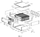
- a battery pack 100 includes a box cover 10 and a battery module 20.
- the box cover 10 is connected to the battery module 20.
- the box cover 10 is connected to a side of the battery module 20, and can cover the battery module 20.
- the box cover 10 covers the side of the battery module 20 along the first direction X. This can protect structures in the battery module 20 and improve the sealing performance of the battery pack 100, thereby improving the reliability of the battery pack 100.
- the box cover 10 is provided with an input terminal 10a and an output terminal 10b.
- the input terminal 10a and the output terminal 10b are electrically connected to an aggregate positive terminal and an aggregate negative terminal of the cell assembly 22 respectively.
- the input terminal 10a and the output terminal 10b are configured for electrical connection with an external device, so as to charge the battery pack 100 or discharge the electric energy of the battery pack 100.
- the battery pack 100 includes a circuit board 30, and the circuit board 30 is connected to a cell assembly 22.
- the circuit board 30 includes a BMS (Battery Management System, battery management system) board.
- the circuit board 30 may be provided with a circuit element, for example, an information collector.
- the battery module 20 includes a housing 21.
- An accommodating space 211 is formed in the housing 21.
- the cell assembly 22 is accommodated in the accommodating space 211.
- the housing 21 may be integrally formed.
- An opening 212 is formed at one end of the accommodating space 211 along the first direction X, and the box cover 10 covers the opening 212.
- the box cover 10 covers the opening 212 of the housing 21 of the battery module 20. This can protect structures in the housing 21 and improve the sealing performance of the battery pack 100, thereby improving the reliability of the battery pack 100.
- the box cover 10 is connected to the housing 21 to cover the opening 212.
- the box cover 10 and the housing 21 may be detachably connected, for example, connected using bolts or buckles. In this way, the box cover 10 can be removed easily, and the housing 21 and the box cover 10 can be maintained separately.
- the box cover 10 and the housing 21 may be permanently connected, for example, connected by means of welding or bonding, so as to improve the stability of connection between the box cover 10 and the housing 21 as well as the performance of sealing between the housing 21 and the box cover 10.
- the housing 21 includes a plurality of walls, and the plurality of walls jointly enclose the accommodating space 211.
- the plurality of walls may be integrally molded to form the housing 21, and the housing 21 may be integrally formed using a method such as casting, injection molding, and stamping.
- a part of the walls may be integrally molded and connected to the other a part of the walls to form a whole, so as to form the housing 21 with the accommodating space 211.
- the walls of the housing 21 may be separately arranged and then connected to form the housing 21.
- the manner of connection between walls may be but is not limited to welding connection and bonding connection.
- the housing 21 includes a first wall 213, a second wall 214, a third wall 215, a fourth wall 216, and a fifth wall 217.
- the first wall 213 and the second wall 214 are arranged opposite to each other along the second direction Y, and the third wall 215 and the fourth wall 216 are arranged opposite to each other along the third direction Z.
- the opening 212 and the fifth wall 217 are arranged opposite to each other along the first direction X.
- the first direction X, the second direction Y, and the third direction Z are perpendicular to each other.
- the third wall 215 bears the gravity of the cell assembly 22, so as to support the cell assembly 22.
- the first wall 213 and the second wall 214 are connected to respectively connected to two ends of the third wall 215 along the second direction Y.
- the first wall 213, the second wall 214, and the third wall 215 may be integrally formed.
- the fourth wall 216 is connected to an end of the first wall 213, the end of the first wall 213 being an end oriented away from the third wall 215, and the fourth wall 216 is connected to an end of the second wall 214, the end of the second wall 214 being an end oriented away from the third wall 215.
- the fourth wall 216 and the first wall 213 may be detachably connected, which facilitates the repair and replacement of the fourth wall 216 and the first wall 213.
- the detachable connection may be a bolt connection, a buckling connection, or the like.
- the second wall 214 and the fourth wall 216 may be permanently connected, which facilitates the formation of the second wall 214 and the fourth wall 216.
- the permanent connection may be a welding connection, a bonding connection, or the like.
- the fourth wall 216 and the second wall 214 may be detachably connected, which facilitates the repair and replacement of the second wall 214 and the fourth wall 216.
- the detachable connection may be a bolt connection, a buckling connection, or the like.
- the first wall 213, the second wall 214, the third wall 215, and the fourth wall 216 are all connected to the fifth wall 217, and the fifth wall 217 and the opening 212 of the accommodating space 211 are arranged opposite to each other along the first direction X.
- the first wall 213, the second wall 214, the third wall 215, and the fourth wall 216 may be permanently connected to the fifth wall 217, for example, connected through welding or bonding.
- the first wall 213, the second wall 214, the third wall 215, and the fourth wall 216 may be detachably connected to the fifth wall 217, which facilitates the repair and replacement of various components of the housing 21.
- the detachable connection may be a bolt connection, a buckling connection, or the like.
- first wall 213, the second wall 214, the third wall 215, the fourth wall 216, and the fifth wall 217 may also be integrally formed, which facilitates the formation of the housing 21. In this way, the housing 21 has high structural strength.
- the third wall 215 is provided with two first fixing portions 2151, and the two first fixing portions 2151 are spaced apart along the second direction Y.
- the first fixing portion 2151 protrudes from the inner surface of the third wall 215.
- the two first fixing portions 2151 can restrict the movement of the cell assembly 22 along the second direction Y and an direction Y' opposite to the second direction, thereby improving the stability of the cell assembly 22 in the housing 21.
- the first fixing portion 2151 may be formed by stamping the outer surface of the third wall 215. During stamping, a depression is formed on the outer surface of the third wall 215, and a protruding first fixing portion 2151 is formed on the inner surface of the third wall 215.
- the inner surface of the third wall 215 refers to a surface of the third wall 215, the surface of the third wall 215 being a surface facing the cell assembly 22 along the third direction Z, and the outer surface of the third wall 215 refers to a surface of the third wall 215, the surface of the third wall 215 being a surface oriented away from the cell assembly 22 along a direction opposite to the third direction Z.
- the fourth wall 216 is provided with two second fixing portions 2161, and the two second fixing portions 2161 are spaced apart along the second direction Y.
- the second fixing portion 2161 protrudes from the inner surface of the fourth wall 216.
- the two second fixing portions 2161 can restrict the movement of the cell assembly 22 along the second direction Y and along the direction Y' opposite to the second direction Y, thereby improving the stability of the cell assembly 22 in the housing 21.
- the second fixing portion 2161 may be formed by stamping the outer surface of the fourth wall 216. During stamping, a depression is formed on the outer surface of the fourth wall 216, and a protruding second fixing portion 2161 is formed on the inner surface of the fourth wall 216.
- the inner surface of the fourth wall 216 refers to a surface of the fourth wall 216, the surface of the fourth wall 216 being a surface facing the cell assembly 22 along the direction opposite to the third direction Z, and the outer surface of the fourth wall 216 refers to a surface of the fourth wall 216, the surface of the fourth wall 216 being a surface oriented away from the cell assembly 22 along the third direction Z.
- the cell assembly 22 includes a plurality of cell units 221, and the plurality of cell units 221 are stacked along the first direction X.
- a plurality of means two or more.
- Each cell unit 221 includes a cell 2211.
- the cell 2211 may be a cell with a hard casing or a pouch cell.
- the cell 2211 includes a cell housing 22111, an electrode assembly 22112, and electrode terminals 22113.
- the electrode assembly 22112 is accommodated in the cell housing 22111.
- the cell housing 22111 may be made of aluminum-plastic film, steel-plastic film, or the like.
- the cell 2211 is a pouch cell.
- the cell housing 22111 includes a main body 22111a and a first sealing portion 22111b. in the second direction Y, the main body 22111a is provided with a first end surface 2211a.
- the first sealing portion 22111b is connected to the first end surface 2211a. along the second direction Y, the first sealing portion 22111b protrudes from the first end surface 2211a.
- the electrode assembly 22112 is accommodated in the main body 22111a.
- the electrode terminals 22113 are connected to the electrode assembly 22112 and extend out of the cell housing 22111 from the first sealing portion 22111b.
- the cell 2211 includes two electrode terminals 22113.
- the two electrode terminals 22113 are both connected to the electrode assembly 22112, the two electrode terminals 22113 have opposite polarities.
- the two electrode terminals 22113 may be located one end of the cell 2211 in the second direction Y, and the two electrode terminals 22113 extend out of the cell housing 22111 from the same first sealing portion 22111b. In this way, the cell assembly 22 can be properly disposed in the housing 21, so that the internal space of the housing 21 is fully utilized and other structures can be electrically connected to the two electrode terminals 22113 conveniently.
- the two electrode terminals 22113 may be located at opposite ends of the cell 2211 respectively.
- the cell housing 22111 includes two first sealing portions 22111b. in the second direction Y, the two first sealing portions 22111b are located on two sides of the main body 22111a respectively.
- One first sealing portion 22111b is connected to the first end surface 2211a of the main body 22111a, and the other first sealing portion 22111b is connected to a second end surface 2211b of the main body 22111a.
- the first end surface 2211a and the second end surface 2211b are arranged opposite to each other along the second direction Y.
- the two electrode terminals 22113 may be located at opposite ends of the cell 2211 respectively, so as to reduce the risk of short circuit of the cell assembly 22.
- the cell housing 22111 includes two second sealing portions 22111c arranged opposite to each other along the third direction Z.
- the two second sealing portions 22111c are located on two sides of the main body 22111a respectively. This not only facilitates the assembly and formation of the cell 2211, but also helps improve the sealing performance of the cell 2211.
- the plurality of cells 2211 may be connected in series or in parallel. Alternatively, some cells 2211 in the plurality of cells 2211 are connected in series and the rest of cells 2211 are connected in parallel.
- the cell assembly 22 further includes a first conductor 222 and a second conductor 223.
- the first conductor 222 is electrically connected to one electrode terminal 22113 of the cell 2211 to form an aggregate positive terminal of the cell assembly 22
- the second conductor 223 is electrically connected to the other electrode terminal 22113 of the cell 2211 to form an aggregate negative terminal of the cell assembly 22.
- the aggregate positive terminal and the aggregate negative terminal are electrically connected to the input terminal 10a and the output terminal 10b respectively.
- the cell unit 221 further includes a first bracket 2212.
- the first bracket 2212 is provided on the cell 2211.
- the main bodies 22111a of cells 2211 of two adjacent cell units 221 are in contact-type connection. When a cell 2211 swells, the adjacent main bodies 22111a abut against each other, so that cells 2211 can pressurize each other.
- the first bracket 2212 includes a first coverage portion 22121.
- the first coverage portion 22121 covers at least a part of the first end surface 2211a. This can mitigate the deformation of the main body 22111a, reduce the risk of bulging on the first end surface 2211a, and improve the reliability of the battery module 20.
- the first coverage portion 22121 may be connected to the first end surface 2211a, or may only be attached to the first end surface 2211a.
- the first bracket 2212 includes two first coverage portions 22121, and the two first coverage portions 22121 are located on two opposite sides of the first sealing portion 22111b along the first direction X.
- the two first coverage portions 22121 respectively cover the parts of the first end surface 2211a located on two sides of the first sealing portion 22111b.
- the two first coverage portions 22121 are located respectively on two opposite sides of the first sealing portion 22111b along the first direction X, so as to strengthen the protection of the cell 2211.
- a part of one first sealing portion 22111b is spaced apart from the first coverage portion 22121 connected to the first sealing portion 22111b. It should be understood that the first coverage portion 22121 covers a part of the corresponding first sealing portion 22111b, and the part of the first sealing portion 22111b not covered by the first coverage portion 22121 can expand under the internal pressure of the cell 2211.
- the first coverage portion 22121 covers at least a part of the first sealing portion 22111b. This can restrain the first sealing portion 22111b, reduce the risk of sealing failure of the first sealing portion 22111b due to internal air pressure of the cell 2211, and improve the sealing performance of the cell 2211.
- the main body 22111a extends beyond the first coverage portion 22121 (as shown in FIG. 13 ).
- two adjacent cell units 221 are provided with a large space at a corresponding position of the first sealing portion 22111b. This is conducive to heat dissipation and swelling of the cell 2211 during cycling.
- the first bracket 2212 is further provided with a first notch 22122b, and the first notch 22122b exposes a part of an end of the first sealing portion 22111b, the end of the first sealing portion 22111b being an end oriented away from the main body 2111a . Therefore, the first notch 22122b can function as a pressure relief valve. To be specific, when the internal pressure of the cell 2211 reaches a threshold, pressure is relieved through the first notch 22122b, thereby reducing the risk of thermal runaway of the battery module 20.
- first notches 22122b There may be one or more first notches 22122b.
- the plurality of first notches 22122b are spaced apart along the third direction Z.
- the cell unit 221 includes a second bracket 2213, and the second bracket 2213 includes a second coverage portion 22131.
- the second coverage portion 22131 covers at least a part of the second end surface 2211b. This can mitigate the deformation of the main body 22111a, reduce the risk of bulging on the second end surface 2211b, and improve the reliability of the battery module 20.
- the second coverage portion 22131 may be connected to the second end surface 2211b, or may only be attached to the second end surface 2211b.
- the second bracket 2213 includes two second coverage portions 22131, and the two second coverage portions 22131 are located on two opposite sides of the other first sealing portion 22111b along the first direction X.
- the two second coverage portions 22131 respectively cover the parts of the second end surface 2211b located on two sides of the first sealing portion 22111b.
- a part of the first sealing portion 22111b corresponding to the second bracket 2213 is spaced apart from the second coverage portion 22131. It should be understood that the second coverage portion 22131 covers a part of the corresponding first sealing portion 22111b, and the part of the first sealing portion 22111b not covered by the second coverage portion 22131 can expand under the internal pressure of the cell 2211.
- the second coverage portion 22131 covers at least a part of the first sealing portion 22111b. This can restrain the first sealing portion 22111b, and reduce the risk of sealing failure of the first sealing portion 22111b due to internal air pressure of the cell 2211.
- the main body 22111a when viewed along the second direction Y, the main body 22111a extends beyond the second coverage portion 22131 in the first direction X (as shown in FIG. 23 ).
- two adjacent cell units 221 are provided with a large space at a corresponding position of the in the accommodating first sealing portion 22111b. This is conducive to heat dissipation and swelling of the cell 2211 during cycling.
- a distance between the second coverage portion 22131 and the elastic member 224 is greater than a distance between a surface of the main body 22111a and the elastic member 224, the second coverage portion 22131 is located on a side of the first sealing portion 22111b, the side of the first sealing portion 22111b being a side facing the elastic member 224, the surface of the main body 22111a being a surface facing the elastic member 224.
- a distance between the second coverage portion 22131, and the elastic member 224 is smaller than a distance between a surface of the main body 22111a and the elastic member 224, the second coverage portion 22131is located on a side of the first sealing portion 22111b, the side of the first sealing portion 22111b being a side oriented away from the elastic member 224, the surface of the main body 22111a being a surface oriented away from the elastic member 224 .
- the second bracket 2213 may not be provided with a notch that functions as a pressure relief valve.
- the second bracket 2213 may further be provided with a second notch (not shown in the figure), and the second notch exposes a part of an end of the first sealing portion 22111b, the end of the first sealing portion 22111b being an end oriented away from the main body 22111a.
- the part of the first sealing portion 22111b located at the second notch is not restrained by the second bracket 2213. Therefore, the second notch can function as a pressure relief valve.
- the internal pressure of the cell 2211 reaches a threshold, pressure is relieved through the second notch, thereby reducing the risk of thermal runaway of the battery module 20.
- the first bracket 2212 and the second bracket 2213 may adopt the same or different structures. In an embodiment of this application, the first bracket 2212 and the second bracket 2213 adopt different structures.
- the first bracket 2212 can be disposed on the cell 2211 in different ways, for example, the first bracket 2212 is bonded to the cell 2211, and the first bracket 2212 is welded to the cell 2211.
- the first bracket 2212 is integrally formed on the cell 2211. This facilitates the connection between the first bracket 2212 and the cell 2211, increases the structural strength of the first bracket 2212, and ensures a stable connection between the cell 2211 and the first bracket 2212.
- the integrated forming method includes but is not limited to casting and injection molding.
- the insulating material solidifies to form the first bracket 2212, and the first bracket 2212 and the cell 2211 are bonded.
- the cell 2211 is placed into a mold, the insulating material is poured into the mold, the insulating material solidifies to form the first bracket 2212 and is bonded with the cell 2211, and then the first bracket 2212 and the cell 2211 are taken out of the mold.
- the insulating material includes but is not limited to a potting compound and polystyrene foam.
- the injection molding process refers to that: the cell 2211 is placed into a mold, the injection molding device heats and melts the insulating material, the melted insulating material flows into the mold, the insulating material solidifies to form the first bracket 2212 and is bonded with the cell 2211, and then the first bracket 2212 and the cell 2211 are taken out of the mold.
- the insulating material includes polyamide.
- the first bracket 2212 is an insulating bracket, which can reduce the risk of short circuit between the first bracket 2212 and the cell 2211.
- the second bracket 2213 may be integrally formed on the cell 2211. This facilitates the connection between the second bracket 2213 and the cell 2211, increases the structural strength of the second bracket 2213, and ensures a stable connection between the cell 2211 and the second bracket 2213.
- the integrated forming method includes but is not limited to casting and injection molding.
- the insulating material solidifies to form the second bracket 2213, and the second bracket 2213 and the cell 2211 are bonded.
- the cell 2211 is placed into a mold, the insulating material is poured into the mold, the insulating material solidifies to form the second bracket 2213 and is bonded with the cell 2211, and then the second bracket 2213 and the cell 2211 are taken out of the mold.
- the insulating material includes but is not limited to a potting compound and polystyrene foam.
- the injection molding process refers to that: the cell 2211 is placed into a mold, the injection molding device heats and melts the insulating material, the melted insulating material flows into the mold, the insulating material solidifies to form the second bracket 2213 and is bonded with the cell 2211, and then the second bracket 2213 and the cell 2211 are taken out of the mold.
- the insulating material includes polyamide.
- the second bracket 2213 is an insulating bracket, which can reduce the risk of short circuit between the second bracket 2213 and the cell 2211.
- the battery module 20 includes an elastic member 224.
- the elastic members 224 and the cell assembly 22 are arranged along the first direction X. When the battery module 20 swells, the elastic member 224 can be compressed along the first direction X to provide space for swelling of the cell assembly 22.
- a material of the elastic member 224 includes but is not limited to metal and plastic.
- the battery module 20 includes a buffer 225.
- the buffer 225 is provided between the elastic member 224 and the cell assembly 22.
- the buffer 225 can provide space for swelling of the cell assembly 22.
- the elastic member 224 and the buffer 225 a large space can be provided for swelling of the cell assembly 22, and the elastic member 224, the buffer 225, and the cell assembly 22 can abut against each other all the time. This helps achieve a compact structure for the battery module 20 and reduce the risk that the battery module 20 moves in the housing 21.
- the buffer 225 includes but is not limited to foam, rubber pad, and silicone.
- the buffer 225 includes a first section 2251.
- the first section 2251 extends beyond the first end surface 2211a close to the buffer 225.
- the second direction Y is perpendicular to the first direction X.
- the first section 2251 may extend beyond the first end surface 2211a only, but does not extend beyond the first coverage portion 22121.
- the entire first section 2251 is located between the first coverage portion 22121 and the elastic member 224.
- the first section 2251 extends beyond the first coverage portion 22121 close to the buffer 225. It can be understood that along the second direction Y, the first section 2251 extends beyond not only the first end surface 2211a but also a surface of the first coverage portion 22121, the surface of the first coverage portion 22121 being a surface oriented away from the first end surface 2211a. In this case, a part of the first section 2251 is located between the first coverage portion 22121 and the elastic member 224, and another part of the first section 2251 extends beyond the space between the first coverage portion 22121 and the elastic member 224. As a result, the first section 2251 can adapt to greater deformation of the first bracket 2212, and the first coverage portion 22121 can still abut against the first section 2251 when the first bracket 2212 suffers great deformation.
- the buffer 225 includes the first section 2251 extending beyond the first end surface 2211a, and at least a part of the first section 2251 is located between the elastic member 224 and the first coverage portion 22121 of the first bracket 2212 closest to the elastic member 224.
- the first coverage portion 22121 moves a small distance towards the elastic member 224, and then the first section 2251 of the buffer 225 abuts against the elastic member 224, restraining the first coverage portion 22121 from moving closer to the elastic member 224.
- This helps restrict the swelling of the first sealing portion 22111b along the first direction X, and reduces the failure risk of the first sealing portion 22111b, thereby improving the reliability of the battery module 20.
- the buffer 225 includes a second section 2252, the first section 2251 extends from the second section 2252, and along the first direction X, a projection of the second section 2252 and a projection of the main body 22111a overlap.
- the second section 2252 is located between the main body 22111a of the cell 2211 and the elastic member 224, the cell 2211 being a cell 2211closest to the elastic member 224 of the cell assembly 22 When the cell 2211 swells, the main body 22111a and the elastic member 224 jointly squeeze the second section 2252 to make it deform, so as to provide space for swelling of the cell 2211.
- the buffer 225 further includes a third section 2253, and the third section 2253 extends from the second section 2252 along the direction Y' opposite to the second direction Y.
- the third section 2253 extends beyond the second end surface 2211b.
- the buffer 225 includes the third section 2253 extending beyond the second end surface 2211b, and at least a part of the third section 2253 is located between the elastic member 224 and the second coverage portion 22131 of the first bracket 2212 closest to the elastic member 224.
- the second coverage portion 22131 moves a small distance towards the elastic member 224, and then the third section 2253 of the buffer 225 abuts against the elastic member 224, restraining the second coverage portion 22131 from moving closer to the elastic member 224.
- This helps restrict the swelling of the first sealing portion 22111b along the first direction X, and reduces the failure risk of the first sealing portion 22111b, thereby improving the reliability of the battery module 20.
- the third section 2253 may extend beyond the second end surface 2211b only, but does not extend beyond the second coverage portion 22131.
- the entire third section 2253 is located between the second coverage portion 22131 and the elastic member 224.
- the third section 2253 extends beyond the second coverage portion 22131 along the direction Y' opposite to the second direction Y. It can be understood that along the direction Y' opposite to the second direction Y, the third section 2253 extends beyond not only the second end surface 2211b but also a surface of the second coverage portion 22131, the surface of the second coverage portion 22131 being a surface oriented away from the second end surface 2211b. In this case, a part of the third section 2253 is located between the second coverage portion 22131 and the elastic member 224, and another part of the third section 2253 extends beyond the space between the second coverage portion 22131 and the elastic member 224 along the direction Y' opposite to the second direction Y. As a result, the third section 2253 can adapt to greater deformation of the second bracket 2213, and the second coverage portion 22131 can still abut against the third section 2253 when the second bracket 2213 suffers great deformation.
- the housing 21 is provided with a restraint member 23, and along the first direction X, the elastic member 224 is located between the buffer 225 and the restraint member 23.
- the restraint member 23 is provided on a side of the elastic member 224, the side of the elastic member 224 being a side oriented away from the buffer 225. This can reduce the risk that the cell assembly 22, the buffer 225, and the elastic member 224 are detached from each other, and reduce the risk that the elastic member 224, the cell assembly 22, and the buffer 225 are detached from the housing 21.
- the housing 21, the cell assembly 22, the elastic member 224, and the buffer 225 can be integrally formed into a compact structure.
- one end of the elastic member 224 is fixed to the buffer 225, and another end of the elastic member 224 is connected to the restraint member 23, so as to improve the stability of the elastic member 224 between the buffer 225 and the restraint member 23.
- one end of the elastic member 224 abuts against the buffer 225 along the first direction X.
- the elastic member 224 and the buffer 225 may directly abut against each other. That is, the elastic member 224 and buffer 225 are in direct contact.
- the elastic member 224 and the buffer 225 may also abut against each other indirectly.
- the elastic member 224 abuts against the restraint member 23 along the first direction X.
- the elastic member 224 and the and the restraint member 23 may directly abut against each other. That is, the elastic member 224 and the and the restraint member 23 are in direct contact.
- the elastic member 224 and the restraint member 23 may also abut against each other indirectly, for example, a buffer structure is provided between the elastic member 224 and the restraint member 23, so that the elastic member 224 and the restraint member 23 indirectly abut against each other through the buffer 225.
- the buffer structure may be foam.
- the elastic member 224 includes a base portion 2241, a connecting portion 2242, and at least one buffer portion 2243.
- the base portion 2241 and the connecting portion 2242 are spaced apart along the first direction X, and the buffer portion 2243 connects the base portion 2241 and the connecting portion 2242.
- the base portion 2241 extends beyond the first section 2251 along the second direction Y, so that the base portion 2241 can apply pressure on the cell assembly 22.
- the base portion 2241 is connected to the buffer 225.
- the base portion 2241 is in contact-type connection with the buffer 225, so that the base portion 2241 abuts against the buffer 225.
- the base portion 2241 and the buffer 225 may be connected through another component.
- the connecting portion 2242 is fixed to the housing 21.
- the connecting portion 2242 is fixed to the restraint member 23.
- fixing includes but is not limited to abutting, bonding, welding, locking through fasteners, and buckling connection.
- the cell assembly 22, the elastic member 224, and the buffer 225 are all accommodated in the housing 21, facilitating the repair of the battery pack 100.
- the connecting portion 2242 abuts against the restraint member 23.
- the buffer portion 2243 can adapt to the change of the distance between the base portion 2241 and the connecting portion 2242, thereby adapting to swelling of the cell 2211.
- the connecting portion 2242 is in contact-type connection with the restraint member 23.
- the connecting portion 2242 and the restraint member 23 may be connected through another component.
- the base portion 2241 extends beyond the first section 2251 along the second direction Y, so that the base portion 2241 can apply a counteracting force to the first section 2251 on a side of the first section 2251, the side of the first section 2251 being a side oriented away from the cell assembly 22, limiting the position of the buffer 225.
- the base portion 2241 extends beyond the third section 2253 along the direction Y' opposite to the second direction Y, so that the base portion 2241 can apply a counteracting force to the third section 2253 on a side of the third section 2253, the side of the third section 2253 being a side oriented away from the cell assembly 22, limiting the position of the buffer 225.
- a part of the first sealing portion 22111b is spaced apart from the first coverage portion 22121, and a clearance is provided between the first sealing portion 22111b and the base portion 2241.
- the clearance may be an air clearance Q1, which facilitates heat dissipation and provides space for swelling of the cell 2211.
- a part of the first sealing portion 22111b is spaced apart from the second coverage portion 22131, and a clearance is provided between the first sealing portion 22111b and the base portion 2241.
- the clearance may be an air clearance Q1, which facilitates heat dissipation and provides space for swelling of the cell 2211.
- the buffer portion 2243 is configured to provide space for swelling of the cell 2211.
- the base portion 2241 squeezes the buffer portion 2243 to reduce the distance between the base portion 2241 and the connecting portion 2242, so as to provide space for swelling of the cell 2211.
- the buffer portion 2243 may be in various structures.
- the buffer portion 2243 is a semicircular arc structure, an S-shaped structure, a Z-shaped structure, or the like.
- the buffer portion 2243 is a bending structure provided between the base portion 2241 and the connecting portion 2242.
- Such structure is simple and easy to manufacture, and can properly adapt to the change of the distance between the base portion 2241 and the connecting portion 2242.
- the buffer portion 2243 includes at least one first bending unit 2243a arranged between the base portion 2241 and the connecting portion 2242, and the first bending unit 2243a includes a first bending portion 22431 and a second bending portion 22432 that are connected, where the first bending portion 22431 and the second bending portion 22432 are arranged at an included angle.
- the first bending portion 22431and the second bending portion 22432 of the buffer portion 2243 are connected and arranged at an included angle, so that the buffer portion 2243 can deform to absorb the acting force produced by a swelling cell 2211.
- the included angle between the first bending portion 22431 and the second bending portion 22432 is B, where 0° ⁇ B ⁇ 90°. That is, the first bending portion 22431 and the second bending portion 22432 may be arranged at an acute angle.
- the buffer portion 2243 may include one or more first bending units 2243a.
- the buffer portion 2243 includes a plurality of first bending units 2243a
- the plurality of first bending units 2243a are sequentially connected along the first direction X. This helps increase the adjustment range of the distance between the base portion 2241 and the connecting portion 2242, so as to better adapt to swelling of the cell 2211.
- the plurality of first bending units 2243a are connected to the base portion 2241 and the connecting portion 2242 respectively.
- the buffer portion 2243 includes one first bending unit 2243a.
- An end of the first bending portion 22431 of the first bending unit 2243a is connected to the base portion 2241, the end of the first bending portion 22431 being an end oriented away from the second bending portion 22432, and an end of the second bending portion 22432 is connected to the connecting portion 2242, the end of the second bending portion 22432 being an end oriented away from the first bending portion 22431.
- the first bending portion 22431 and the base portion 2241 are arranged at an acute angle
- the second bending portion 22432 and the connecting portion 2242 are arranged at an acute angle.
- the buffer portion 2243 having one first bending unit 2243a, the base portion 2241, and the connecting portion 2242 form an M-shaped elastic member 224.
- the distance between the base portion 2241 and the connecting portion 2242 along the first direction X decreases, the angle between the first bending portion 22431 and the second bending portion 22432 decreases, the angle between the base portion 2241 and first bending portion 22431 decreases, and the angle between the connecting portion 2242 and the second bending portion 22432 decreases.
- the elastic member 224 may include one or more buffer portions 2243.
- the elastic member 224 includes a plurality of buffer portions 2243, as shown in FIG. 24 to FIG. 27 , the plurality of buffer portions 2243 are spaced apart along the second direction Y.
- Each buffer portion 2243 connects the base portion 2241 and the connecting portion 2242.
- the plurality of buffer portions 2243 are connected between the base portion 2241 and the connecting portion 2242, which can adapt to the change of the distance between the base portion 2241 and the connecting portion 2242.
- the elastic member 224 further includes a plurality of connecting portions 2242, where each buffer portion 2243 corresponds to one connecting portion 2242, and each connecting portion 2242 is connected to the base portion 2241 through one buffer portion 2243.
- the buffer portion 2243 and the connecting portion 2242 may be provided in plurality, so as to absorb the acting force produced by a swelling cell 2211.
- the elastic member 224 includes two buffer portions 2243 and two connecting portions 2242, where the two buffer portions 2243 are spaced apart along the third direction Z, the two connecting portions 2242 are spaced apart along the third direction Z, and the two buffer portions 2243 are respectively connected to two ends of the base portion 2241 along the second direction Y.
- the two buffer portions 2243 are respectively connected to two edges of the base portion 2241 along the second direction Y.
- the first direction X, the second direction Y, and the third direction Z are perpendicular to each other.
- Two buffer portions 2243 and two connecting portions 2242 are provided, and the two buffer portions 2243 are spaced apart along the first direction X, so as to utilize the assembly space properly.
- the base portion 2241 is provided with a stiffener 22411, so that the base portion 2241 has high strength and is not easy to be damaged.
- the stiffener 22411 may be in a strip structure extending along the third direction Z. There may be one or more stiffeners 22411. In an embodiment where a plurality of stiffeners 22411 are provided, the plurality of stiffeners 22411 are spaced apart along the second direction Y. A shown in FIG. 24 , FIG. 26, and FIG. 27 , four stiffeners 22411 are provided.
- the elastic member 224 may be formed in different manners.
- the base portion 2241, the connecting portion 2242, and the buffer portion 2243 are independent of each other, and they are connected into a whole by means of detachable connection or permanent connection to form the elastic member 224.
- the elastic member 224 may also be integrally formed.
- the base portion 2241, the buffer portion 2243, and the connecting portion 2242 are formed by bending one piece of plate. The structure is simple and easy to manufacture.
- the base portion 2241 and the buffer portion 2243 are firmly connected, and the buffer portion 2243 and the connecting portion 2242 are firmly connected.
- the restraint member 23 may be the box cover 10.
- the box cover 10 can not only restrict the movement of the elastic member 224 along the first direction X, but also cover the opening 212.
- a separate restraint member 23 does not need to be provided in the battery module 20, which simplifies the structure of the battery module 20.
- the restraint member 23 and the box cover 10 may be two independent components.
- the restraint member 23 is provided at the end of the housing 21 having an opening 212.
- the cell assembly 22, the buffer 225, and the elastic member 224 can be confined in the housing 21, and then the housing 21, the cell assembly 22, the buffer 225, and the elastic member 224 can be integrally formed.
- the box cover 10 can be removed without affecting the relative positional relationship among the cell assembly 22, the buffer 225, and the elastic member 224, so that the box cover 10 can be removed and mounted separately.
- the restraint member 23 includes a first restraint member 231 and a second restraint member 232, and the first restraint member 231 and the second restraint member 232 are spaced apart in the second direction Y.
- the first restraint member 231 is connected to the first wall 213, the second restraint member 232 is connected to the second wall 214, and the connecting portion 2242 is fixed to the first restraint member 231 and the second restraint member 232.
- the first restraint member 231 and the second restraint member 232 are respectively connected to the first wall 213 and the second wall 214 arranged opposite to each other along the second direction Y. This reduces the risk that the first restraint member 231 and the second restraint member 232 interfere with other structures.
- the first restraint member 231 and the second restraint member 232 jointly limit the position of the elastic member 224, so that the elastic member 224 can more reliably abut between the restraint member and 23 the buffer 225.
- the first restraint member 231 is connected to an end of the first wall 213 located at the opening 212 of the housing 21.
- the first restraint member 231 protrudes from the inner surface of the first wall 213 in a direction from the first wall 213 to the second wall 214.
- the first restraint member 231 and the first wall 213 may be separately arranged and then connected into a whole.
- the first restraint member 231 and the first wall 213 may be permanently connected, for example, connected through welding or bonding, so as to improve the stability of connection between the first restraint member 231 and the first wall 213.
- the first restraint member 231 and the first wall 213 may be detachably connected, for example, connected using bolts, which facilitates the repair and replacement of the first restraint member 231. If either of the first wall 213 and the first restraint member 231 is damaged, only the damaged one needs to be replaced, thereby reducing costs.
- first restraint member 231 and the first wall 213 may also be integrally formed.
- the first restraint member 231 may be a flange structure provided at an end portion of the first wall 213, so that the first restraint member 231 can be formed easily.
- the second restraint member 232 is connected to an end of the second wall 214 located at the opening 212 of the housing 21.
- the second restraint member 232 protrudes from the inner surface of the second wall 214 in a direction from the second wall 214 to the first wall 213.
- the second restraint member 232 and the second wall 214 may be separately arranged and then connected into a whole.
- the second restraint member 232 and the second wall 214 may be permanently connected, for example, connected through welding or bonding, so as to improve the stability of connection between the second restraint member 232 and the second wall 214.
- the second restraint member 232 and the second wall 214 may be detachably connected, for example, connected using bolts, which facilitates the repair and replacement of the second restraint member 232. If either of the second wall 214 and the second restraint member 232 is damaged, only the damaged one needs to be replaced, thereby reducing costs.
- the second restraint member 232 and the second wall 214 may also be integrally formed.
- the second restraint member 232 may be a flange structure provided at an end portion of the second wall 214, so that the second restraint member 232 can be formed easily.
- the elastic member 224 includes two extensions 22421 of the connecting portion extending beyond two ends of the base portion 2241, and the two extensions 22421 are respectively connected to two ends of the base portion 2241 in the second direction Y.
- the two extensions 22421 are fixed to the first restraint member 231 and the second restraint member 232 respectively.
- Each connecting portion 2242 is connected to two extensions 22421, where one of the two extensions 22421 extends beyond one end of the base portion 2241 along the second direction Y, and the other one of the two extensions 22421 extends beyond another end of the base portion 2241 along the direction Y' opposite to the second direction Y.
- the extensions 22421 are fixed to the first restraint member 231 and the second restraint member 232 respectively. In this way, when the cell 2211 swells, the connecting portion 2242 deforms along a direction oriented away from the cell assembly 22, so as to adapt to swelling of the cell 2211 and provide space for the deformed cell 2211.
- the restraint member 23 includes a third restraint member 233 and a fourth restraint member 234, and the third restraint member 233 and the fourth restraint member 234 are spaced apart along the third direction Z.
- the third restraint member 233 is connected to the third wall 215, and the fourth restraint member 234 is connected to the fourth wall 216.
- the connecting portion 2242 is fixed to the third restraint member 233 and the fourth restraint member 234.
- the third restraint member 233 is fixed to the third wall 215, and the fourth restraint member 234 is fixed to the fourth wall 216, reducing the risk that the third restraint member 233 and the fourth restraint member 234 interfere with other structures.
- the third restraint member 233 and the fourth restraint member 234 jointly confine the cell assembly 22, the buffer 225, and the elastic member 224 in the housing 21, reducing the risk that the cell assembly 22, the buffer 225, and the elastic member 224 are detached from the housing 21. In this way, the elastic member 224 can more stably abut between the restraint member 23 and the buffer 225.
- the third restraint member 233 is connected to an end of the third wall 215 located at the opening 212 of the housing 21.
- the third restraint member 233 protrudes from the inner surface of the third wall 215 along a direction from the third wall 215 to the fourth wall 216.
- the third restraint member 233 and the third wall 215 may be separately arranged and then connected into a whole.
- the third restraint member 233 and the third wall 215 may be permanently connected, for example, connected through welding or bonding, so as to improve the stability of connection between the third restraint member 233 and the third wall 215.
- the third restraint member 233 and the third wall 215 may be detachably connected, for example, connected using bolts, which facilitates the repair and replacement of the third restraint member 233. If either of the third wall 215 and the third restraint member 233 is damaged, only the damaged one needs to be replaced, thereby reducing costs. In some other embodiments, the third restraint member 233 and the third wall 215 may also be integrally formed.
- the third restraint member 233 may be a flange structure provided at an end portion of the third wall 215, so that the third restraint member 233 can be formed easily.
- third restraint members 233 There may be one or more third restraint members 233. In an embodiment where a plurality of third restraint members 233 are provided, the plurality of third restraint members 233 are spaced apart along the second direction Y. As shown in FIG. 2 , FIG. 3 , FIG. 22, and FIG. 23 , two third restraint members 233 are provided.
- the fourth restraint member 234 is connected to an end of the fourth wall 216 located at the opening 212 of the housing 21.
- the fourth restraint member 234 protrudes from the inner surface of the fourth wall 216 along a direction from the fourth wall 216 to the third wall 215.
- the fourth restraint member 234 and the fourth wall 216 may be separately arranged and then connected into a whole.
- the fourth restraint member 234 and the fourth wall 216 may be permanently connected, for example, connected through welding or bonding, so as to improve the stability of connection between the fourth restraint member 234 and the fourth wall 216.
- the fourth restraint member 234 and the fourth wall 216 may be detachably connected, for example, connected using bolts, which facilitates the repair and replacement of the fourth restraint member 234. If either of the fourth wall 216 and the fourth restraint member 234 is damaged, only the damaged one needs to be replaced, thereby reducing costs.
- the fourth restraint member 234 and the fourth wall 216 may also be integrally formed.
- the fourth restraint member 234 may be a flange structure provided at an end portion of the fourth wall 216, so that the fourth restraint member 234 can be formed easily.
- fourth restraint members 23 There may be one or more fourth restraint members 234.
- the plurality of fourth restraint members 234 are spaced apart along the second direction Y. As shown in FIG. 2 , FIG. 3 , FIG. 22, and FIG. 23 , two fourth restraint members 234 are provided.
- the battery module 20 further includes a first insulator 24 (as shown in FIG. 2 ).
- the first insulator 24 is provided between the third wall 215 and the cell assembly 22.
- the first insulator 24 can insulate the third wall 215 from the cell assembly 22 and prevent the friction between the cell assembly 22 and the third wall 215, thereby increasing the service life of the housing 21.
- a projection of the cell assembly 22 located within a projection of the first insulator 24. In this case, even when the cell assembly 22 swells and moves a certain distance in the housing 21, the first insulator 24 is still located between the third wall 215 and the cell assembly 22.
- An embodiment of this application further provides an electric device, and the electric device includes the battery pack 100 according to any one of the foregoing embodiments.
- the battery pack 100 according to any one of the foregoing embodiments has high reliability, which helps improve the reliability of the electric device powered by the battery module 20 and the battery pack 100.
- the foregoing descriptions are merely preferred some embodiments of this application which are not intended to limit this application. Persons skilled in the art understand that this application may have various modifications and variations. Any modifications, equivalent replacements, and improvements made without departing from principle of this application shall fall within the protection scope of this application.
Landscapes
- Chemical & Material Sciences (AREA)
- Chemical Kinetics & Catalysis (AREA)
- Electrochemistry (AREA)
- General Chemical & Material Sciences (AREA)
- Battery Mounting, Suspending (AREA)
- Sealing Battery Cases Or Jackets (AREA)
Abstract
A battery module (20) includes a cell assembly (22), an elastic member (224), and a buffer (225), the cell assembly (22) includes a plurality of cell units (221) stacked along a first direction (X), the cell units (221) includes a cell (2211) and a first bracket. The cell (2211) includes a cell housing (22111), an electrode assembly (22112), and electrode terminals (22113), the cell housing (22111) includes a main body (22111a) and a first sealing portion (22111b), the main body (22111a) is provided with a first end surface (2211a), the first sealing portion (22111b) is connected to the first end surface (2211a). The first bracket (2212) includes a first coverage portion (22121), the first coverage portion (22121) covers at least a part of the first end surface (2211a). Along the first direction (X), the buffer (225) is provided between the elastic member (224) and the cell assembly (22). The buffer (225) includes a first section (2251), along a second direction (Y), the first section (2251) extends beyond the first end surface (2211a) close to the buffer (225), where the first direction (X) is perpendicular to the second direction (Y).
Description
- This application relates to the field of battery technologies, and in particular, to a battery module, a battery pack, and an electric device.
- Batteries are widely used in portable electronic devices, electric vehicles, electric tools, drones, energy storage devices, and other fields. As the application environments and conditions become more complex, higher requirements are imposed on the reliability of batteries.
- Some embodiments of this application provide a battery module, a battery pack, and an electric device, so as to improve the reliability of batteries.
- According to a first aspect, the battery module includes a cell assembly, an elastic member, and a buffer, where the cell assembly includes a plurality of cell units stacked along a first direction, and each cell unit includes a cell and a first bracket. The cell includes a cell housing, an electrode assembly, and electrode terminals, where the cell housing includes a main body and a first sealing portion, the cell housing includes a main body and a first sealing portion, and the electrode terminals extend out of the cell housing from the first sealing portion. The main body is provided with a first end surface, and the first sealing portion is connected to the first end surface. The first bracket includes a first coverage portion, and the first coverage portion covers at least a part of the first end surface. The elastic member and the cell assembly are arranged along the first direction. Along the first direction, the buffer is provided between the elastic member and the cell assembly. The buffer includes a first section, and along a second direction, the first section extends beyond the first end surface close to the buffer, where the first direction is perpendicular to the second direction.
- In this technical solution, the buffer includes the first section extending beyond the first end surface close to the buffer, and along the first direction, at least a part of the first section is located between the elastic member and the first coverage portion closest to the elastic member. When the cell swells, the first coverage portion closest to the elastic member moves towards the elastic member, and then the first section of the buffer abuts against the elastic member, restraining the first coverage portion from moving closer to the elastic member. This helps restrict the swelling of the first sealing portion along the first direction, and reduces the failure risk of the first sealing portion, thereby improving the reliability of the battery module.
- In one or more of the foregoing optional embodiments, along a second direction, the first section extends beyond the first coverage portion close to the buffer.
- In this technical solution, along the second direction, the first section extends beyond the first coverage portion close to the buffer, so that the first section can adapt to greater deformation of the first bracket.
- In one or more of the foregoing optional embodiments, the main body extends beyond the first coverage portion in the first direction.
- In this technical solution, when viewed along the second direction, the main body extends beyond the first coverage portion in the first direction, so that two adjacent cell units are provided with a large space at a corresponding position of the first sealing portion. This is conducive to heat dissipation and swelling of the cell during cycling.
- In one or more of the foregoing optional embodiments, the main bodies of adjacent cells are in contact.
- In this technical solution, the main bodies of adjacent cells are in contact. When a cell swells, the adjacent main bodies abut against the cell, so that cells can pressurize each other.
- In one or more of the foregoing optional embodiments, the elastic member includes a base portion, a connecting portion, and at least one buffer portion, where the base portion and the connecting portion are spaced apart along the first direction, the base portion is connected to the buffer, and the base portion extends beyond the first section along the second direction.
- In this technical solution, the base portion extends beyond the first section along the second direction, so that the base portion can apply a counteracting force to the first section on a side of the first section, the side of the first section being a side oriented away from the cell assembly, limiting the position of the buffer.
- In one or more of the foregoing optional embodiments, the buffer portion includes a first bending unit, and the first bending unit includes a first bending portion and a second bending portion that are connected, where the first bending portion and the second bending portion are arranged at an included angle.
- In this technical solution, the first bending portion and the second bending portion of the buffer portion are connected and arranged at an included angle, so that the buffer portion can deform to absorb the acting force produced by a swelling cell.
- In one or more of the foregoing optional embodiments, a part of the first sealing portion is spaced apart from the first coverage portion, and a clearance is provided between the first sealing portion and the base portion.
- In this technical solution, a clearance is provided between the first sealing portion and the base portion, which facilitates heat dissipation and provides space for swelling of the cell.
- In one or more of the foregoing optional embodiments, the buffer portion is configured to provide space for swelling of the cell.
- In this technical solution, the buffer portion is configured to provide space for swelling of the cell. When the cell swells, the base portion and the connecting portion squeeze the buffer portion to reduce the distance between the base portion and the connecting portion, so as to provide space for swelling of the cell.
- In one or more of the foregoing optional embodiments, the battery module further includes a housing, and the connecting portion is fixed to the housing, where the cell assembly, the elastic member, and the buffer are all accommodated in the housing.
- In this technical solution, the cell assembly, the elastic member, and the buffer are accommodated in the housing, making the structure of the battery module more compact. The connecting portion is fixed to the housing, which can improve the stability of the elastic member in the housing and reduce the risk of jumping.
- In one or more of the foregoing optional embodiments, the buffer includes a second section, the first section extends from the second section, and along the first direction, a projection of the second section and a projection of the main body overlap.
- In this technical solution, along the first direction, the projection of the second section and the projection of the main body overlap. When a cell swells, the main body and the elastic member jointly squeeze the second section to make it deform, so as to provide space for swelling of the cell.
- In one or more of the foregoing optional embodiments, the first coverage portion covers at least a part of the first sealing portion.
- In this technical solution, the first coverage portion covers at least a part of the first sealing portion. This can restrain the first sealing portion and reduce the risk of sealing failure of the first sealing portion due to air pressure inside the cell.
- In one or more of the foregoing optional embodiments, the first bracket is integrally formed on the cell.
- In this technical solution, the first bracket is integrally formed on the cell. This facilitates the connection between the first bracket and the cell, increases the structural strength of the first bracket, and ensures a stable connection between the cell and the first bracket.
- In one or more of the foregoing optional embodiments, the first bracket is integrally injection-molded on the cell.
- In this technical solution, the first bracket is integrally injection-molded on the cell. This facilitates the connection between the first bracket and the cell, increases the structural strength of the first bracket, and ensures a stable connection between the cell and the first bracket.
- In one or more of the foregoing optional embodiments, the battery module further includes a housing, and the cell assembly, the elastic member, and the buffer are all accommodated in the housing. The housing is provided with a restraint member, and along the first direction, the elastic member is located between the buffer and the restraint member. The elastic member includes a base portion, a connecting portion, and at least one buffer portion, where the base portion and the connecting portion are spaced apart along the first direction and abut against the buffer and the restraint member respectively, and the buffer portion connects the base portion and the connecting portion.
- In this technical solution, the restraint member is provided on a side of the elastic member, the side of the elastic member being a side oriented away from the buffer. This can reduce the risk that the elastic member, the buffer, and the cell assembly are detached from each other, and reduce the risk that the elastic member, the cell assembly, and the buffer are detached from the housing. In this case, the housing, the cell assembly, the elastic member, and the buffer can be integrally formed into a compact structure. The base portion and the connecting portion abut against the buffer and the restraint member respectively, so that the buffer and the restraint member can interact with the elastic member. In this way, the buffer portion can adapt to the change of the distance between the base portion and the connecting portion, so as to provide space for swelling of the cell.
- In one or more of the foregoing optional embodiments, both the buffer portion and the connecting portion are provided in plurality, and each connecting portion is connected to the base portion through one buffer portion.
- In this technical solution, the buffer portion and the connecting portion may be provided in plurality, so as to better absorb the acting force produced by swelling of the cell.
- In one or more of the foregoing optional embodiments, two buffer portions and two connecting portions are provided. The two buffer portions are respectively connected to two edges of the base portion in a third direction, where the first direction, the second direction, and the third direction are perpendicular to each other.
- In this technical solution, two buffer portions and two connecting portions are provided, and the two buffer portions are spaced apart along the first direction, so as to utilize the assembly space properly.
- In one or more of the foregoing optional embodiments, an opening is provided at one end of the housing along the first direction, and the restraint member is provided at the end of the housing having the opening.
- In this technical solution, the restraint member is provided at the end of the housing having the opening. In this way, the cell assembly, the buffer, and the elastic member can be confined in the housing, and then the housing, the cell assembly, the buffer, and the elastic member can be formed in to an integrated structure. This ensures a stable relative positional relationship among the housing, the cell assembly, the buffer, and the elastic member, thereby improving the structural stability of the battery module. The box cover can be removed without affecting the relative positional relationship among the cell assembly, the buffer, and the elastic member, so that the box cover can be removed and mounted separately.
- In one or more of the foregoing optional embodiments, the housing includes a first wall and a second wall arranged opposite to each other along the second direction, and the restraint member includes a first restraint member and a second restraint member spaced apart along the second direction, where the first restraint member and the second restraint member are connected to the first wall and the second wall respectively, and the connecting portion abuts against the first restraint member and the second restraint member.
- In this technical solution, the first restraint member and the second restraint member are respectively connected to the first wall and the second wall arranged opposite to each other along the second direction. This reduces the risk that the first restraint member and the second restraint member interfere with other structures. The first restraint member and the second restraint member jointly limit the position of the elastic member, so that the elastic member can more reliably abut between the restraint member and the buffer.
- In one or more of the foregoing optional embodiments, along the second direction, the connecting portion is provided with two extensions extending beyond two ends of the base portion, and the two extensions abut against the first restraint member and the second restraint member respectively.
- In this technical solution, the extensions abut against the first restraint member and the second restraint member respectively. When the cell swells, the connecting portion deforms along a direction oriented away from the cell assembly, so as to adapt to swelling of the cell and provide space for the deformed cell.
- In one or more of the foregoing optional embodiments, the housing includes a third wall and a fourth wall arranged opposite to each other along the third direction, where the first direction, the second direction, and the third direction are perpendicular to each other. The restraint member includes a third restraint member and a fourth restraint member spaced apart along the third direction, where the third restraint member and the fourth restraint member are connected to the third wall and the fourth wall respectively, and the connecting portion abuts against the third restraint member and the fourth restraint member.
- In this technical solution, the third restraint member and the fourth restraint member are connected to the third wall and the fourth wall respectively, reducing the risk that the third restraint member and the fourth restraint member interfere with other structures. The third restraint member and the fourth restraint member jointly confine the cell assembly, the buffer, and the elastic member in the housing, reducing the risk that the cell assembly, the buffer, and the elastic member are detached from the housing. In this way, the elastic member can more stably abut between the restraint member and the buffer.
- In one or more of the foregoing optional embodiments, an embodiment of this application provides a battery pack, where the battery pack includes a box cover and the battery module according to any one of the foregoing embodiments, and the box cover is connected to the battery module.
- In this technical solution, the box cover is connected to the battery module. This can protect structures in the battery module and improve the sealing performance of the battery pack, thereby improving the reliability of the battery pack. The battery module according to any one of the foregoing embodiments has high reliability, and therefore the battery pack using the battery module also has high reliability.
- In one or more of the foregoing optional embodiments, an embodiment of this application further provides an electric device, and the electric device includes the battery pack according to any one of the foregoing embodiments.
- In this technical solution, the battery pack according to any one of the foregoing embodiments has high reliability, which helps improve the reliability of the electric device powered by such battery module and battery pack.
- To explain the technical solutions in some embodiments of this application more clearly, the following briefly describes the accompanying drawings required for the embodiments. It should be understood that the accompanying drawings below illustrate only some embodiments of this application.
-
FIG. 1 is a schematic diagram of a battery pack according to some embodiments of this application; -
FIG. 2 is an exploded view of a battery pack according to some embodiments of this application; -
FIG. 3 is an exploded view of a housing according to some embodiments of this application; -
FIG. 4 is a schematic structural diagram of a second wall according to some embodiments of this application; -
FIG. 5 is a schematic structural diagram of a cell assembly according to some embodiments of this application; -
FIG. 6 is a schematic structural diagram of a cell according to some embodiments of this application; -
FIG. 7 is an exploded view of a cell according to some embodiments of this application; -
FIG. 8 is a schematic structural diagram of a cell unit according to some embodiments of this application; -
FIG. 9 is an enlarged view of position A1 inFIG. 8 ; -
FIG. 10 is a schematic structural diagram of a cell unit according to some embodiments of this application from another angle of view; -
FIG. 11 is an enlarged view of position A2 inFIG. 10 ; -
FIG. 12 is a schematic diagram of the cooperation among a cell assembly, an elastic member, and a buffer according to some embodiments of this application; -
FIG. 13 is an enlarged view of position A3 inFIG. 12 ; -
FIG. 14 is an enlarged view of position A31 inFIG. 13 ; -
FIG. 15 is a sectional view of a battery pack according to some embodiments of this application; -
FIG. 16 is an enlarged view of position A4 inFIG. 15 ; -
FIG. 17 is an enlarged view of position A41 inFIG. 16 ; -
FIG. 18 is an enlarged view of position A5 inFIG. 12 ; -
FIG. 19 is an enlarged view of position A51 inFIG. 18 ; -
FIG. 20 is an enlarged view of position A6 inFIG. 15 ; -
FIG. 21 is an enlarged view of position A61 inFIG. 20 ; -
FIG. 22 is a schematic diagram of the cooperation between a a part of the housing and an elastic member; -
FIG. 23 is a schematic structural diagram of a battery module according to some embodiments of this application; -
Fig. 24 is a schematic structural diagram of an elastic member according to some embodiments of this application; -
FIG. 25 is a schematic structural diagram of an elastic member according to some embodiments of this application from another angle of view; -
FIG. 26 is a view of an elastic member according to some embodiments of this application when viewed along a first direction; and -
FIG. 27 is a view of an elastic member according to some embodiments of this application when viewed along a direction opposite to a first direction. - Reference signs: 100: battery pack; 10: box cover; 10a: input terminal; 10b: output terminal; 20: battery module; 21: housing; 211: accommodating space; 212: opening; 213: first wall; 214: second wall; 215: third wall; 2151: first fixing portion; 216: fourth wall; 2161: second fixing portion; 217: fifth wall; 22: cell assembly; 221: cell unit; 2211: cell; 2211a: first end surface; 2211b: second end surface; 22111: cell housing; 22111a: main body; 22111b: first sealing portion; 22111c: second sealing portion; 22112: electrode assembly; 22113: electrode terminal; 2212: first bracket; 22121: first coverage portion; 22122b: first notch; 2213: second bracket; 22131: second coverage portion; 222: first conductor; 223: second conductor; 224: elastic member; 2241: base portion; 22411: stiffener; 2242: connecting portion; 22421: extension; 2243: buffer portion; 2243a: first bending unit; 22431: first bending portion; 22432: second bending portion; 225: buffer; 2251: first section; 2252: second section; 2253: third section; 23: restraint member; 231: first restraint member; 232: second restraint member; 233: third restraint member; 234: fourth restraint member; 24: first insulator; 30: circuit board; X: first direction; Y: second direction; Y': direction opposite the second direction; Z: third direction; and Q1: air clearance.
- To make the objectives, technical solutions, and advantages of the embodiments of this application clearer, the following clearly and completely describes the technical solutions in some embodiments of this application with reference to the accompanying drawings in some embodiments of this application. Apparently, some described embodiments are some but not all embodiments of this application. Generally, the components of the embodiments of this application as described and illustrated in the accompanying drawings herein can be arranged and designed in a variety of configurations.
- Therefore, the following detailed description of some embodiments of this application as provided in the accompanying drawings is not intended to limit the scope of this application but merely to represent selected embodiments of this application. It should be noted that, without conflict, some embodiments and features in the embodiments in this application may be combined with each other.
- It should be noted that similar reference numerals and letters indicate similar items in the following drawings, and therefore once an item is defined in one drawing, it does not need to be further defined or explained in the subsequent drawings.
- In the description of some embodiments of this application, it should be noted that the orientations or positional relationships as indicated are orientations or positional relationships based on the accompanying drawings, or conventional orientations or positional relationships of products of this application, or orientations or positional relationships as conventionally understood by persons skilled in the art, and the orientations or positional relationships as indicated are merely for ease and brevity of description of this application rather than indicating or implying that the apparatuses or elements mentioned must have specific orientations or must be constructed or manipulated according to specific orientations, and therefore cannot be understood as limitations on this application. In addition, the terms "first", "second", "third", and the like are merely intended for distinguishing purposes and shall not be understood as any indication or implication of relative importance.
- Currently, from a perspective of market development, application of battery modules is being more extensive. Battery modules are widely used in electric vehicles such as electric bicycles, electric motorcycles, and electric cars, electric tools, drones, energy storage devices, and other fields. With continuous extension of application fields of battery modules, market demands for the battery modules are also expanding.
- Along with the development of battery technologies, many design factors should be considered, for example, performance parameters such as energy density, cycle life, discharge capacity, and charge and discharge rate. In addition, reliability of batteries is also a major factor as environmental conditions and/or internal conditions of the batteries change.
- With the charge/discharge cycling of a battery, gas accumulates inside the cells of the battery and the cells swell continuously. If the swelling is not limited to a certain extent, seals on the cells are likely to be broken by the gas inside the cells, causing sealing failure of the cells and affecting the reliability of the battery.
- To solve the problem of low reliability of the battery caused by increased air pressure in the cells, an embodiment of this application provides a battery module. The battery module includes a cell assembly, an elastic member, and a buffer, where the cell assembly includes a plurality of cell units stacked along a first direction, and each cell unit includes a cell and a first bracket. The cell includes a cell housing, an electrode assembly, and electrode terminals, where the cell housing includes a main body and a first sealing portion, and the electrode terminals extend out of the cell housing from the first sealing portion. The main body is provided with a first end surface, and the first sealing portion is connected to the first end surface. The first bracket includes a first coverage portion, and the first coverage portion covers at least a part of the first end surface. The elastic member and the cell assembly are arranged along the first direction. Along the first direction, the buffer is provided between the elastic member and the cell assembly. The buffer includes a first section, and along a second direction, the first section extends beyond the first end surface close to the buffer, where the first direction is perpendicular to the second direction.
- The buffer includes the first section extending beyond the first end surface close to the buffer, and along the first direction, at least a part of the first section is located between the elastic member and the first coverage portion closest to the elastic member. When the cell swells, the first coverage portion closest to the elastic member moves a small distance towards the elastic member, and then the first section of the buffer abuts against the elastic member, restraining the first coverage portion from moving closer to the elastic member. This helps restrict the swelling of the first sealing portion along the first direction, and reduces the failure risk of the first sealing portion, thereby improving the reliability of the battery module.
- An embodiment of this application provides an electric device using a battery pack or battery module as the power source. The electric device may be but is not limited to an electronic device, an electric tool, an electric vehicle, a drone, or an energy storage device. The electronic device may include a mobile phone, a tablet, a laptop computer, and the like. The electric tool may include an electric drill, an electric saw, and the like. The electric vehicle may include an electric car, an electric motorcycle, an electric bicycle, and the like.
- As shown in
FIG. 1 andFIG. 2 , abattery pack 100 includes abox cover 10 and abattery module 20. Thebox cover 10 is connected to thebattery module 20. - Along a first direction X, the
box cover 10 is connected to a side of thebattery module 20, and can cover thebattery module 20. The box cover 10 covers the side of thebattery module 20 along the first direction X. This can protect structures in thebattery module 20 and improve the sealing performance of thebattery pack 100, thereby improving the reliability of thebattery pack 100. - The
box cover 10 is provided with aninput terminal 10a and an output terminal 10b. Theinput terminal 10a and the output terminal 10b are electrically connected to an aggregate positive terminal and an aggregate negative terminal of thecell assembly 22 respectively. Theinput terminal 10a and the output terminal 10b are configured for electrical connection with an external device, so as to charge thebattery pack 100 or discharge the electric energy of thebattery pack 100. - In some embodiments, the
battery pack 100 includes acircuit board 30, and thecircuit board 30 is connected to acell assembly 22. - In some embodiments, the
circuit board 30 includes a BMS (Battery Management System, battery management system) board. Thecircuit board 30 may be provided with a circuit element, for example, an information collector. - The
battery module 20 includes ahousing 21. Anaccommodating space 211 is formed in thehousing 21. Thecell assembly 22 is accommodated in theaccommodating space 211. - In some embodiments, the
housing 21 may be integrally formed. Anopening 212 is formed at one end of theaccommodating space 211 along the first direction X, and thebox cover 10 covers theopening 212. The box cover 10 covers theopening 212 of thehousing 21 of thebattery module 20. This can protect structures in thehousing 21 and improve the sealing performance of thebattery pack 100, thereby improving the reliability of thebattery pack 100. - The
box cover 10 is connected to thehousing 21 to cover theopening 212. Thebox cover 10 and thehousing 21 may be detachably connected, for example, connected using bolts or buckles. In this way, thebox cover 10 can be removed easily, and thehousing 21 and thebox cover 10 can be maintained separately. Thebox cover 10 and thehousing 21 may be permanently connected, for example, connected by means of welding or bonding, so as to improve the stability of connection between thebox cover 10 and thehousing 21 as well as the performance of sealing between thehousing 21 and thebox cover 10. - As shown in
FIG. 2 andFIG. 3 , thehousing 21 includes a plurality of walls, and the plurality of walls jointly enclose theaccommodating space 211. The plurality of walls may be integrally molded to form thehousing 21, and thehousing 21 may be integrally formed using a method such as casting, injection molding, and stamping. - Alternatively, a part of the walls may be integrally molded and connected to the other a part of the walls to form a whole, so as to form the
housing 21 with theaccommodating space 211. - In some other embodiments, the walls of the
housing 21 may be separately arranged and then connected to form thehousing 21. The manner of connection between walls may be but is not limited to welding connection and bonding connection. - As shown in
FIG. 2 andFIG. 3 , thehousing 21 includes afirst wall 213, asecond wall 214, athird wall 215, afourth wall 216, and afifth wall 217. - The
first wall 213 and thesecond wall 214 are arranged opposite to each other along the second direction Y, and thethird wall 215 and thefourth wall 216 are arranged opposite to each other along the third direction Z. - The
opening 212 and thefifth wall 217 are arranged opposite to each other along the first direction X. The first direction X, the second direction Y, and the third direction Z are perpendicular to each other. - In some embodiments, the
third wall 215 bears the gravity of thecell assembly 22, so as to support thecell assembly 22. Thefirst wall 213 and thesecond wall 214 are connected to respectively connected to two ends of thethird wall 215 along the second direction Y. - The
first wall 213, thesecond wall 214, and thethird wall 215 may be integrally formed. Thefourth wall 216 is connected to an end of thefirst wall 213, the end of thefirst wall 213 being an end oriented away from thethird wall 215, and thefourth wall 216 is connected to an end of thesecond wall 214, the end of thesecond wall 214 being an end oriented away from thethird wall 215. - The
fourth wall 216 and thefirst wall 213 may be detachably connected, which facilitates the repair and replacement of thefourth wall 216 and thefirst wall 213. The detachable connection may be a bolt connection, a buckling connection, or the like. - The
second wall 214 and thefourth wall 216 may be permanently connected, which facilitates the formation of thesecond wall 214 and thefourth wall 216. The permanent connection may be a welding connection, a bonding connection, or the like. - The
fourth wall 216 and thesecond wall 214 may be detachably connected, which facilitates the repair and replacement of thesecond wall 214 and thefourth wall 216. The detachable connection may be a bolt connection, a buckling connection, or the like. - The
first wall 213, thesecond wall 214, thethird wall 215, and thefourth wall 216 are all connected to thefifth wall 217, and thefifth wall 217 and theopening 212 of theaccommodating space 211 are arranged opposite to each other along the first direction X. - The
first wall 213, thesecond wall 214, thethird wall 215, and thefourth wall 216 may be permanently connected to thefifth wall 217, for example, connected through welding or bonding. - The
first wall 213, thesecond wall 214, thethird wall 215, and thefourth wall 216 may be detachably connected to thefifth wall 217, which facilitates the repair and replacement of various components of thehousing 21. The detachable connection may be a bolt connection, a buckling connection, or the like. - In some other embodiments, the
first wall 213, thesecond wall 214, thethird wall 215, thefourth wall 216, and thefifth wall 217 may also be integrally formed, which facilitates the formation of thehousing 21. In this way, thehousing 21 has high structural strength. - As shown in
FIG. 2 andFIG. 3 , thethird wall 215 is provided with twofirst fixing portions 2151, and the twofirst fixing portions 2151 are spaced apart along the second direction Y. - The
first fixing portion 2151 protrudes from the inner surface of thethird wall 215. When thethird wall 215 supports thecell assembly 22, the twofirst fixing portions 2151 can restrict the movement of thecell assembly 22 along the second direction Y and an direction Y' opposite to the second direction, thereby improving the stability of thecell assembly 22 in thehousing 21. - The
first fixing portion 2151 may be formed by stamping the outer surface of thethird wall 215. During stamping, a depression is formed on the outer surface of thethird wall 215, and a protrudingfirst fixing portion 2151 is formed on the inner surface of thethird wall 215. - The inner surface of the
third wall 215 refers to a surface of thethird wall 215, the surface of thethird wall 215 being a surface facing thecell assembly 22 along the third direction Z, and the outer surface of thethird wall 215 refers to a surface of thethird wall 215, the surface of thethird wall 215 being a surface oriented away from thecell assembly 22 along a direction opposite to the third direction Z. - As shown in
FIG. 4 , thefourth wall 216 is provided with twosecond fixing portions 2161, and the twosecond fixing portions 2161 are spaced apart along the second direction Y. - The
second fixing portion 2161 protrudes from the inner surface of thefourth wall 216. The twosecond fixing portions 2161 can restrict the movement of thecell assembly 22 along the second direction Y and along the direction Y' opposite to the second direction Y, thereby improving the stability of thecell assembly 22 in thehousing 21. - The
second fixing portion 2161 may be formed by stamping the outer surface of thefourth wall 216. During stamping, a depression is formed on the outer surface of thefourth wall 216, and a protrudingsecond fixing portion 2161 is formed on the inner surface of thefourth wall 216. - The inner surface of the
fourth wall 216 refers to a surface of thefourth wall 216, the surface of thefourth wall 216 being a surface facing thecell assembly 22 along the direction opposite to the third direction Z, and the outer surface of thefourth wall 216 refers to a surface of thefourth wall 216, the surface of thefourth wall 216 being a surface oriented away from thecell assembly 22 along the third direction Z. - As shown in
FIG. 5 andFIG. 6 , thecell assembly 22 includes a plurality ofcell units 221, and the plurality ofcell units 221 are stacked along the first direction X. "A plurality of" means two or more. Eachcell unit 221 includes acell 2211. Thecell 2211 may be a cell with a hard casing or a pouch cell. Thecell 2211 includes acell housing 22111, anelectrode assembly 22112, andelectrode terminals 22113. Theelectrode assembly 22112 is accommodated in thecell housing 22111. Thecell housing 22111 may be made of aluminum-plastic film, steel-plastic film, or the like. - In
FIG. 6 andFIG. 7 , thecell 2211 is a pouch cell. As shown inFIG. 6 andFIG. 7 , thecell housing 22111 includes amain body 22111a and a first sealing portion 22111b. in the second direction Y, themain body 22111a is provided with afirst end surface 2211a. Thefirst sealing portion 22111b is connected to thefirst end surface 2211a. along the second direction Y, thefirst sealing portion 22111b protrudes from thefirst end surface 2211a. Theelectrode assembly 22112 is accommodated in themain body 22111a. Theelectrode terminals 22113 are connected to theelectrode assembly 22112 and extend out of thecell housing 22111 from thefirst sealing portion 22111b. - The
cell 2211 includes twoelectrode terminals 22113. The twoelectrode terminals 22113 are both connected to theelectrode assembly 22112, the twoelectrode terminals 22113 have opposite polarities. - In some embodiments, the two
electrode terminals 22113 may be located one end of thecell 2211 in the second direction Y, and the twoelectrode terminals 22113 extend out of thecell housing 22111 from the samefirst sealing portion 22111b. In this way, thecell assembly 22 can be properly disposed in thehousing 21, so that the internal space of thehousing 21 is fully utilized and other structures can be electrically connected to the twoelectrode terminals 22113 conveniently. - As shown in
FIG. 5 to FIG. 7 , in some other embodiments, the twoelectrode terminals 22113 may be located at opposite ends of thecell 2211 respectively. Thecell housing 22111 includes two first sealing portions 22111b. in the second direction Y, the twofirst sealing portions 22111b are located on two sides of themain body 22111a respectively. Onefirst sealing portion 22111b is connected to thefirst end surface 2211a of themain body 22111a, and the otherfirst sealing portion 22111b is connected to asecond end surface 2211b of themain body 22111a. Thefirst end surface 2211a and thesecond end surface 2211b are arranged opposite to each other along the second direction Y. The twoelectrode terminals 22113 may be located at opposite ends of thecell 2211 respectively, so as to reduce the risk of short circuit of thecell assembly 22. - In some embodiments, the
cell housing 22111 includes twosecond sealing portions 22111c arranged opposite to each other along the third direction Z. Along the third direction Z, the twosecond sealing portions 22111c are located on two sides of themain body 22111a respectively. This not only facilitates the assembly and formation of thecell 2211, but also helps improve the sealing performance of thecell 2211. - The plurality of
cells 2211 may be connected in series or in parallel. Alternatively, somecells 2211 in the plurality ofcells 2211 are connected in series and the rest ofcells 2211 are connected in parallel. - As shown in
FIG. 5 , thecell assembly 22 further includes afirst conductor 222 and asecond conductor 223. Thefirst conductor 222 is electrically connected to oneelectrode terminal 22113 of thecell 2211 to form an aggregate positive terminal of thecell assembly 22, and thesecond conductor 223 is electrically connected to theother electrode terminal 22113 of thecell 2211 to form an aggregate negative terminal of thecell assembly 22. The aggregate positive terminal and the aggregate negative terminal are electrically connected to theinput terminal 10a and the output terminal 10b respectively. - As shown in
FIG. 5 ,FIG. 8 ,FIG. 9 , andFIG. 10 , in some embodiments, thecell unit 221 further includes afirst bracket 2212. Thefirst bracket 2212 is provided on thecell 2211. - In some embodiments, the
main bodies 22111a ofcells 2211 of twoadjacent cell units 221 are in contact-type connection. When acell 2211 swells, the adjacentmain bodies 22111a abut against each other, so thatcells 2211 can pressurize each other. - In some embodiments, the
first bracket 2212 includes afirst coverage portion 22121. Thefirst coverage portion 22121 covers at least a part of thefirst end surface 2211a. This can mitigate the deformation of themain body 22111a, reduce the risk of bulging on thefirst end surface 2211a, and improve the reliability of thebattery module 20. Thefirst coverage portion 22121 may be connected to thefirst end surface 2211a, or may only be attached to thefirst end surface 2211a. - In this embodiment, the
first bracket 2212 includes twofirst coverage portions 22121, and the twofirst coverage portions 22121 are located on two opposite sides of thefirst sealing portion 22111b along the first direction X. The twofirst coverage portions 22121 respectively cover the parts of thefirst end surface 2211a located on two sides of thefirst sealing portion 22111b. The twofirst coverage portions 22121 are located respectively on two opposite sides of thefirst sealing portion 22111b along the first direction X, so as to strengthen the protection of thecell 2211. - In some embodiments, a part of one
first sealing portion 22111b is spaced apart from thefirst coverage portion 22121 connected to thefirst sealing portion 22111b. It should be understood that thefirst coverage portion 22121 covers a part of the corresponding first sealingportion 22111b, and the part of thefirst sealing portion 22111b not covered by thefirst coverage portion 22121 can expand under the internal pressure of thecell 2211. - In some embodiments, the
first coverage portion 22121 covers at least a part of thefirst sealing portion 22111b. This can restrain thefirst sealing portion 22111b, reduce the risk of sealing failure of thefirst sealing portion 22111b due to internal air pressure of thecell 2211, and improve the sealing performance of thecell 2211. - In some embodiments, in the first direction X, the
main body 22111a extends beyond the first coverage portion 22121 (as shown inFIG. 13 ). In this case, twoadjacent cell units 221 are provided with a large space at a corresponding position of thefirst sealing portion 22111b. This is conducive to heat dissipation and swelling of thecell 2211 during cycling. - The
first bracket 2212 is further provided with afirst notch 22122b, and thefirst notch 22122b exposes a part of an end of thefirst sealing portion 22111b, the end of thefirst sealing portion 22111b being an end oriented away from the main body 2111a . Therefore, thefirst notch 22122b can function as a pressure relief valve. To be specific, when the internal pressure of thecell 2211 reaches a threshold, pressure is relieved through thefirst notch 22122b, thereby reducing the risk of thermal runaway of thebattery module 20. - There may be one or more
first notches 22122b. The plurality offirst notches 22122b are spaced apart along the third direction Z. - In an embodiment where the two
electrode terminals 22113 are respectively located at opposite ends of thecell 2211 along the second direction Y, as shown inFIG. 11 ,FIG. 12 , andFIG. 13 , thecell unit 221 includes asecond bracket 2213, and thesecond bracket 2213 includes asecond coverage portion 22131. Thesecond coverage portion 22131 covers at least a part of thesecond end surface 2211b. This can mitigate the deformation of themain body 22111a, reduce the risk of bulging on thesecond end surface 2211b, and improve the reliability of thebattery module 20. Thesecond coverage portion 22131 may be connected to thesecond end surface 2211b, or may only be attached to thesecond end surface 2211b. - In this embodiment, the
second bracket 2213 includes twosecond coverage portions 22131, and the twosecond coverage portions 22131 are located on two opposite sides of the otherfirst sealing portion 22111b along the first direction X. The twosecond coverage portions 22131 respectively cover the parts of thesecond end surface 2211b located on two sides of thefirst sealing portion 22111b. - In some embodiments, a part of the
first sealing portion 22111b corresponding to thesecond bracket 2213 is spaced apart from thesecond coverage portion 22131. It should be understood that thesecond coverage portion 22131 covers a part of the corresponding first sealingportion 22111b, and the part of thefirst sealing portion 22111b not covered by thesecond coverage portion 22131 can expand under the internal pressure of thecell 2211. - In some embodiments, the
second coverage portion 22131 covers at least a part of thefirst sealing portion 22111b. This can restrain thefirst sealing portion 22111b, and reduce the risk of sealing failure of thefirst sealing portion 22111b due to internal air pressure of thecell 2211. - In some embodiments, when viewed along the second direction Y, the
main body 22111a extends beyond thesecond coverage portion 22131 in the first direction X (as shown inFIG. 23 ). In this case, twoadjacent cell units 221 are provided with a large space at a corresponding position of the in the accommodatingfirst sealing portion 22111b. This is conducive to heat dissipation and swelling of thecell 2211 during cycling. - A distance between the
second coverage portion 22131 and theelastic member 224 is greater than a distance between a surface of themain body 22111a and theelastic member 224, thesecond coverage portion 22131 is located on a side of thefirst sealing portion 22111b, the side of thefirst sealing portion 22111b being a side facing theelastic member 224, the surface of themain body 22111a being a surface facing theelastic member 224. A distance between thesecond coverage portion 22131, and theelastic member 224 is smaller than a distance between a surface of themain body 22111a and theelastic member 224, the second coverage portion 22131is located on a side of thefirst sealing portion 22111b, the side of thefirst sealing portion 22111b being a side oriented away from theelastic member 224, the surface of themain body 22111a being a surface oriented away from theelastic member 224 . - In an embodiment where the
first bracket 2212 is provided with thefirst notch 22122b, thesecond bracket 2213 may not be provided with a notch that functions as a pressure relief valve. In some other embodiments, thesecond bracket 2213 may further be provided with a second notch (not shown in the figure), and the second notch exposes a part of an end of thefirst sealing portion 22111b, the end of thefirst sealing portion 22111b being an end oriented away from themain body 22111a. The part of thefirst sealing portion 22111b located at the second notch is not restrained by thesecond bracket 2213. Therefore, the second notch can function as a pressure relief valve. To be specific, when the internal pressure of thecell 2211 reaches a threshold, pressure is relieved through the second notch, thereby reducing the risk of thermal runaway of thebattery module 20. - The
first bracket 2212 and thesecond bracket 2213 may adopt the same or different structures. In an embodiment of this application, thefirst bracket 2212 and thesecond bracket 2213 adopt different structures. - The
first bracket 2212 can be disposed on thecell 2211 in different ways, for example, thefirst bracket 2212 is bonded to thecell 2211, and thefirst bracket 2212 is welded to thecell 2211. - In some embodiments, the
first bracket 2212 is integrally formed on thecell 2211. This facilitates the connection between thefirst bracket 2212 and thecell 2211, increases the structural strength of thefirst bracket 2212, and ensures a stable connection between thecell 2211 and thefirst bracket 2212. The integrated forming method includes but is not limited to casting and injection molding. - In some embodiments, after an insulating material is poured around the
cell 2211 by using the casting process, the insulating material solidifies to form thefirst bracket 2212, and thefirst bracket 2212 and thecell 2211 are bonded. For example, thecell 2211 is placed into a mold, the insulating material is poured into the mold, the insulating material solidifies to form thefirst bracket 2212 and is bonded with thecell 2211, and then thefirst bracket 2212 and thecell 2211 are taken out of the mold. - In some embodiments, the insulating material includes but is not limited to a potting compound and polystyrene foam.
- In some embodiments, the injection molding process refers to that: the
cell 2211 is placed into a mold, the injection molding device heats and melts the insulating material, the melted insulating material flows into the mold, the insulating material solidifies to form thefirst bracket 2212 and is bonded with thecell 2211, and then thefirst bracket 2212 and thecell 2211 are taken out of the mold. Optionally, the insulating material includes polyamide. - In some embodiments, the
first bracket 2212 is an insulating bracket, which can reduce the risk of short circuit between thefirst bracket 2212 and thecell 2211. - In an embodiment where the
cell unit 221 includes asecond bracket 2213, thesecond bracket 2213 may be integrally formed on thecell 2211. This facilitates the connection between thesecond bracket 2213 and thecell 2211, increases the structural strength of thesecond bracket 2213, and ensures a stable connection between thecell 2211 and thesecond bracket 2213. The integrated forming method includes but is not limited to casting and injection molding. - In some embodiments, after an insulating material is poured around the
cell 2211 by using the casting process, the insulating material solidifies to form thesecond bracket 2213, and thesecond bracket 2213 and thecell 2211 are bonded. For example, thecell 2211 is placed into a mold, the insulating material is poured into the mold, the insulating material solidifies to form thesecond bracket 2213 and is bonded with thecell 2211, and then thesecond bracket 2213 and thecell 2211 are taken out of the mold. - In some embodiments, the insulating material includes but is not limited to a potting compound and polystyrene foam.
- In some embodiments, the injection molding process refers to that: the
cell 2211 is placed into a mold, the injection molding device heats and melts the insulating material, the melted insulating material flows into the mold, the insulating material solidifies to form thesecond bracket 2213 and is bonded with thecell 2211, and then thesecond bracket 2213 and thecell 2211 are taken out of the mold. Optionally, the insulating material includes polyamide. - In some embodiments, the
second bracket 2213 is an insulating bracket, which can reduce the risk of short circuit between thesecond bracket 2213 and thecell 2211. - In some embodiments, as shown in
FIG. 14 to FIG. 23 , thebattery module 20 includes anelastic member 224. Theelastic members 224 and thecell assembly 22 are arranged along the first direction X. When thebattery module 20 swells, theelastic member 224 can be compressed along the first direction X to provide space for swelling of thecell assembly 22. - A material of the
elastic member 224 includes but is not limited to metal and plastic. - As shown in
FIG. 12 to FIG. 21 , in some embodiments, thebattery module 20 includes abuffer 225. Along the first direction X, thebuffer 225 is provided between theelastic member 224 and thecell assembly 22. - When the
cell assembly 22 swells, thebuffer 225 can provide space for swelling of thecell assembly 22. Through the cooperation between theelastic member 224 and thebuffer 225, a large space can be provided for swelling of thecell assembly 22, and theelastic member 224, thebuffer 225, and thecell assembly 22 can abut against each other all the time. This helps achieve a compact structure for thebattery module 20 and reduce the risk that thebattery module 20 moves in thehousing 21. - The
buffer 225 includes but is not limited to foam, rubber pad, and silicone. - As shown in
FIG. 14 to FIG. 19 , in some embodiments, thebuffer 225 includes afirst section 2251. along the second direction Y, thefirst section 2251 extends beyond thefirst end surface 2211a close to thebuffer 225. The second direction Y is perpendicular to the first direction X. - In some embodiments, along the second direction Y, the
first section 2251 may extend beyond thefirst end surface 2211a only, but does not extend beyond thefirst coverage portion 22121. The entirefirst section 2251 is located between thefirst coverage portion 22121 and theelastic member 224. - In some embodiments, along the second direction Y, the
first section 2251 extends beyond thefirst coverage portion 22121 close to thebuffer 225. It can be understood that along the second direction Y, thefirst section 2251 extends beyond not only thefirst end surface 2211a but also a surface of thefirst coverage portion 22121, the surface of thefirst coverage portion 22121 being a surface oriented away from thefirst end surface 2211a. In this case, a part of thefirst section 2251 is located between thefirst coverage portion 22121 and theelastic member 224, and another part of thefirst section 2251 extends beyond the space between thefirst coverage portion 22121 and theelastic member 224. As a result, thefirst section 2251 can adapt to greater deformation of thefirst bracket 2212, and thefirst coverage portion 22121 can still abut against thefirst section 2251 when thefirst bracket 2212 suffers great deformation. - Therefore, the
buffer 225 includes thefirst section 2251 extending beyond thefirst end surface 2211a, and at least a part of thefirst section 2251 is located between theelastic member 224 and thefirst coverage portion 22121 of thefirst bracket 2212 closest to theelastic member 224. - When the
cell 2211 swells, thefirst coverage portion 22121 moves a small distance towards theelastic member 224, and then thefirst section 2251 of thebuffer 225 abuts against theelastic member 224, restraining thefirst coverage portion 22121 from moving closer to theelastic member 224. This helps restrict the swelling of thefirst sealing portion 22111b along the first direction X, and reduces the failure risk of thefirst sealing portion 22111b, thereby improving the reliability of thebattery module 20. - In some embodiments, the
buffer 225 includes asecond section 2252, thefirst section 2251 extends from thesecond section 2252, and along the first direction X, a projection of thesecond section 2252 and a projection of themain body 22111a overlap. - It can be understood that the
second section 2252 is located between themain body 22111a of thecell 2211 and theelastic member 224, thecell 2211 being a cell 2211closest to theelastic member 224 of thecell assembly 22 When thecell 2211 swells, themain body 22111a and theelastic member 224 jointly squeeze thesecond section 2252 to make it deform, so as to provide space for swelling of thecell 2211. - In an embodiment where the two
electrode terminals 22113 are located at the opposite ends of thecell 2211 and thesecond bracket 2213 further includes asecond coverage portion 22131, as shown inFIG. 12 ,FIG. 15 andFIG. 18 toFIG. 21 , along the direction Y' opposite to the second direction Y, thebuffer 225 further includes athird section 2253, and thethird section 2253 extends from thesecond section 2252 along the direction Y' opposite to the second direction Y. Thethird section 2253 extends beyond thesecond end surface 2211b. - In some embodiments, the
buffer 225 includes thethird section 2253 extending beyond thesecond end surface 2211b, and at least a part of thethird section 2253 is located between theelastic member 224 and thesecond coverage portion 22131 of thefirst bracket 2212 closest to theelastic member 224. - When the
cell 2211 swells, thesecond coverage portion 22131 moves a small distance towards theelastic member 224, and then thethird section 2253 of thebuffer 225 abuts against theelastic member 224, restraining thesecond coverage portion 22131 from moving closer to theelastic member 224. This helps restrict the swelling of thefirst sealing portion 22111b along the first direction X, and reduces the failure risk of thefirst sealing portion 22111b, thereby improving the reliability of thebattery module 20. - Along the direction Y' opposite to the second direction Y, the
third section 2253 may extend beyond thesecond end surface 2211b only, but does not extend beyond thesecond coverage portion 22131. The entirethird section 2253 is located between thesecond coverage portion 22131 and theelastic member 224. - In some other embodiments, the
third section 2253 extends beyond thesecond coverage portion 22131 along the direction Y' opposite to the second direction Y. It can be understood that along the direction Y' opposite to the second direction Y, thethird section 2253 extends beyond not only thesecond end surface 2211b but also a surface of thesecond coverage portion 22131, the surface of thesecond coverage portion 22131 being a surface oriented away from thesecond end surface 2211b. In this case, a part of thethird section 2253 is located between thesecond coverage portion 22131 and theelastic member 224, and another part of thethird section 2253 extends beyond the space between thesecond coverage portion 22131 and theelastic member 224 along the direction Y' opposite to the second direction Y. As a result, thethird section 2253 can adapt to greater deformation of thesecond bracket 2213, and thesecond coverage portion 22131 can still abut against thethird section 2253 when thesecond bracket 2213 suffers great deformation. - As shown in
FIG. 2 ,FIG. 3 ,FIG. 22, and FIG. 23 , in some embodiments, thehousing 21 is provided with arestraint member 23, and along the first direction X, theelastic member 224 is located between thebuffer 225 and therestraint member 23. Therestraint member 23 is provided on a side of theelastic member 224, the side of theelastic member 224 being a side oriented away from thebuffer 225. This can reduce the risk that thecell assembly 22, thebuffer 225, and theelastic member 224 are detached from each other, and reduce the risk that theelastic member 224, thecell assembly 22, and thebuffer 225 are detached from thehousing 21. In this case, thehousing 21, thecell assembly 22, theelastic member 224, and thebuffer 225 can be integrally formed into a compact structure. - In the first direction X, one end of the
elastic member 224 is fixed to thebuffer 225, and another end of theelastic member 224 is connected to therestraint member 23, so as to improve the stability of theelastic member 224 between thebuffer 225 and therestraint member 23. - In some embodiments, one end of the
elastic member 224 abuts against thebuffer 225 along the first direction X. Theelastic member 224 and thebuffer 225 may directly abut against each other. That is, theelastic member 224 and buffer 225 are in direct contact. Theelastic member 224 and thebuffer 225 may also abut against each other indirectly. - Another end of the
elastic member 224 abuts against therestraint member 23 along the first direction X. Theelastic member 224 and the and therestraint member 23 may directly abut against each other. That is, theelastic member 224 and the and therestraint member 23 are in direct contact. Theelastic member 224 and therestraint member 23 may also abut against each other indirectly, for example, a buffer structure is provided between theelastic member 224 and therestraint member 23, so that theelastic member 224 and therestraint member 23 indirectly abut against each other through thebuffer 225. The buffer structure may be foam. - As shown in
FIG. 24 to FIG. 27 , in some embodiments, theelastic member 224 includes abase portion 2241, a connectingportion 2242, and at least onebuffer portion 2243. Thebase portion 2241 and the connectingportion 2242 are spaced apart along the first direction X, and thebuffer portion 2243 connects thebase portion 2241 and the connectingportion 2242. - In some embodiments, the
base portion 2241 extends beyond thefirst section 2251 along the second direction Y, so that thebase portion 2241 can apply pressure on thecell assembly 22. - In some embodiments, the
base portion 2241 is connected to thebuffer 225. Optionally, thebase portion 2241 is in contact-type connection with thebuffer 225, so that thebase portion 2241 abuts against thebuffer 225. Optionally, thebase portion 2241 and thebuffer 225 may be connected through another component. - In some embodiments, the connecting
portion 2242 is fixed to thehousing 21. Optionally, the connectingportion 2242 is fixed to therestraint member 23. - In some embodiments, fixing includes but is not limited to abutting, bonding, welding, locking through fasteners, and buckling connection.
- In some embodiments, the
cell assembly 22, theelastic member 224, and thebuffer 225 are all accommodated in thehousing 21, facilitating the repair of thebattery pack 100. - The connecting
portion 2242 abuts against therestraint member 23. When thecell 2211 swells, the distance between thebase portion 2241 and the connectingportion 2242 along the first direction X changes. Thebuffer portion 2243 can adapt to the change of the distance between thebase portion 2241 and the connectingportion 2242, thereby adapting to swelling of thecell 2211. Optionally, the connectingportion 2242 is in contact-type connection with therestraint member 23. Optionally, the connectingportion 2242 and therestraint member 23 may be connected through another component. - In some embodiments, the
base portion 2241 extends beyond thefirst section 2251 along the second direction Y, so that thebase portion 2241 can apply a counteracting force to thefirst section 2251 on a side of thefirst section 2251, the side of thefirst section 2251 being a side oriented away from thecell assembly 22, limiting the position of thebuffer 225. - In some embodiments, the
base portion 2241 extends beyond thethird section 2253 along the direction Y' opposite to the second direction Y, so that thebase portion 2241 can apply a counteracting force to thethird section 2253 on a side of thethird section 2253, the side of thethird section 2253 being a side oriented away from thecell assembly 22, limiting the position of thebuffer 225. - In some embodiments, a part of the
first sealing portion 22111b is spaced apart from thefirst coverage portion 22121, and a clearance is provided between thefirst sealing portion 22111b and thebase portion 2241. The clearance may be an air clearance Q1, which facilitates heat dissipation and provides space for swelling of thecell 2211. - In some embodiments, a part of the
first sealing portion 22111b is spaced apart from thesecond coverage portion 22131, and a clearance is provided between thefirst sealing portion 22111b and thebase portion 2241. The clearance may be an air clearance Q1, which facilitates heat dissipation and provides space for swelling of thecell 2211. - The
buffer portion 2243 is configured to provide space for swelling of thecell 2211. When thecell 2211 swells, thebase portion 2241 squeezes thebuffer portion 2243 to reduce the distance between thebase portion 2241 and the connectingportion 2242, so as to provide space for swelling of thecell 2211. - The
buffer portion 2243 may be in various structures. For example, thebuffer portion 2243 is a semicircular arc structure, an S-shaped structure, a Z-shaped structure, or the like. As shown inFIG. 24 to FIG. 27 , in some embodiments, thebuffer portion 2243 is a bending structure provided between thebase portion 2241 and the connectingportion 2242. Such structure is simple and easy to manufacture, and can properly adapt to the change of the distance between thebase portion 2241 and the connectingportion 2242. - As shown in
FIG. 25 , in some embodiments, thebuffer portion 2243 includes at least onefirst bending unit 2243a arranged between thebase portion 2241 and the connectingportion 2242, and thefirst bending unit 2243a includes afirst bending portion 22431 and asecond bending portion 22432 that are connected, where thefirst bending portion 22431 and thesecond bending portion 22432 are arranged at an included angle. - The first bending portion 22431and the
second bending portion 22432 of thebuffer portion 2243 are connected and arranged at an included angle, so that thebuffer portion 2243 can deform to absorb the acting force produced by a swellingcell 2211. - The included angle between the
first bending portion 22431 and thesecond bending portion 22432 is B, where 0° < B < 90°. That is, thefirst bending portion 22431 and thesecond bending portion 22432 may be arranged at an acute angle. - The
buffer portion 2243 may include one or morefirst bending units 2243a. In an embodiment where thebuffer portion 2243 includes a plurality offirst bending units 2243a, the plurality offirst bending units 2243a are sequentially connected along the first direction X. This helps increase the adjustment range of the distance between thebase portion 2241 and the connectingportion 2242, so as to better adapt to swelling of thecell 2211. - The plurality of
first bending units 2243a are connected to thebase portion 2241 and the connectingportion 2242 respectively. - As shown in
FIG. 27 , thebuffer portion 2243 includes onefirst bending unit 2243a. An end of thefirst bending portion 22431 of thefirst bending unit 2243a is connected to thebase portion 2241, the end of thefirst bending portion 22431 being an end oriented away from thesecond bending portion 22432, and an end of thesecond bending portion 22432 is connected to the connectingportion 2242, the end of thesecond bending portion 22432 being an end oriented away from thefirst bending portion 22431. Thefirst bending portion 22431 and thebase portion 2241 are arranged at an acute angle, and thesecond bending portion 22432 and the connectingportion 2242 are arranged at an acute angle. Thebuffer portion 2243 having onefirst bending unit 2243a, thebase portion 2241, and the connectingportion 2242 form an M-shapedelastic member 224. - When the
cell 2211 swells, the distance between thebase portion 2241 and the connectingportion 2242 along the first direction X decreases, the angle between thefirst bending portion 22431 and thesecond bending portion 22432 decreases, the angle between thebase portion 2241 and first bendingportion 22431 decreases, and the angle between the connectingportion 2242 and thesecond bending portion 22432 decreases. - The
elastic member 224 may include one ormore buffer portions 2243. In an embodiment where theelastic member 224 includes a plurality ofbuffer portions 2243, as shown inFIG. 24 to FIG. 27 , the plurality ofbuffer portions 2243 are spaced apart along the second direction Y. Eachbuffer portion 2243 connects thebase portion 2241 and the connectingportion 2242. The plurality ofbuffer portions 2243 are connected between thebase portion 2241 and the connectingportion 2242, which can adapt to the change of the distance between thebase portion 2241 and the connectingportion 2242. - As shown in
FIG. 24 to FIG. 27 , in an embodiment where theelastic member 224 includes a plurality ofbuffer portions 2243, theelastic member 224 further includes a plurality of connectingportions 2242, where eachbuffer portion 2243 corresponds to one connectingportion 2242, and each connectingportion 2242 is connected to thebase portion 2241 through onebuffer portion 2243. Thebuffer portion 2243 and the connectingportion 2242 may be provided in plurality, so as to absorb the acting force produced by a swellingcell 2211. - For example, as shown in
FIG. 24 to FIG. 27 , theelastic member 224 includes twobuffer portions 2243 and two connectingportions 2242, where the twobuffer portions 2243 are spaced apart along the third direction Z, the two connectingportions 2242 are spaced apart along the third direction Z, and the twobuffer portions 2243 are respectively connected to two ends of thebase portion 2241 along the second direction Y. Specifically, the twobuffer portions 2243 are respectively connected to two edges of thebase portion 2241 along the second direction Y. The first direction X, the second direction Y, and the third direction Z are perpendicular to each other. - Two
buffer portions 2243 and two connectingportions 2242 are provided, and the twobuffer portions 2243 are spaced apart along the first direction X, so as to utilize the assembly space properly. - As shown in
FIG. 24 to FIG. 27 , in some embodiments, thebase portion 2241 is provided with astiffener 22411, so that thebase portion 2241 has high strength and is not easy to be damaged. - The
stiffener 22411 may be in a strip structure extending along the third direction Z. There may be one ormore stiffeners 22411. In an embodiment where a plurality ofstiffeners 22411 are provided, the plurality ofstiffeners 22411 are spaced apart along the second direction Y. A shown inFIG. 24 ,FIG. 26, and FIG. 27 , fourstiffeners 22411 are provided. - The
elastic member 224 may be formed in different manners. For example, thebase portion 2241, the connectingportion 2242, and thebuffer portion 2243 are independent of each other, and they are connected into a whole by means of detachable connection or permanent connection to form theelastic member 224. In some other embodiments, theelastic member 224 may also be integrally formed. For example, thebase portion 2241, thebuffer portion 2243, and the connectingportion 2242 are formed by bending one piece of plate. The structure is simple and easy to manufacture. In addition, thebase portion 2241 and thebuffer portion 2243 are firmly connected, and thebuffer portion 2243 and the connectingportion 2242 are firmly connected. - In some embodiments, the
restraint member 23 may be thebox cover 10. To be specific, along the first direction X, thebase portion 2241 and the connectingportion 2242 of theelastic member 224 abut against thebuffer 225 and thebox cover 10 respectively. In this case, thebox cover 10 can not only restrict the movement of theelastic member 224 along the first direction X, but also cover theopening 212. As a result, aseparate restraint member 23 does not need to be provided in thebattery module 20, which simplifies the structure of thebattery module 20. - In some other embodiments, the
restraint member 23 and thebox cover 10 may be two independent components. Therestraint member 23 is provided at the end of thehousing 21 having anopening 212. In this way, thecell assembly 22, thebuffer 225, and theelastic member 224 can be confined in thehousing 21, and then thehousing 21, thecell assembly 22, thebuffer 225, and theelastic member 224 can be integrally formed. Thebox cover 10 can be removed without affecting the relative positional relationship among thecell assembly 22, thebuffer 225, and theelastic member 224, so that thebox cover 10 can be removed and mounted separately. - As shown in
FIG. 2 ,FIG. 3 ,FIG. 22, and FIG. 23 , in some embodiments, therestraint member 23 includes afirst restraint member 231 and asecond restraint member 232, and thefirst restraint member 231 and thesecond restraint member 232 are spaced apart in the second direction Y. - In some embodiments, the
first restraint member 231 is connected to thefirst wall 213, thesecond restraint member 232 is connected to thesecond wall 214, and the connectingportion 2242 is fixed to thefirst restraint member 231 and thesecond restraint member 232. - The
first restraint member 231 and thesecond restraint member 232 are respectively connected to thefirst wall 213 and thesecond wall 214 arranged opposite to each other along the second direction Y. This reduces the risk that thefirst restraint member 231 and thesecond restraint member 232 interfere with other structures. Thefirst restraint member 231 and thesecond restraint member 232 jointly limit the position of theelastic member 224, so that theelastic member 224 can more reliably abut between the restraint member and 23 thebuffer 225. - The
first restraint member 231 is connected to an end of thefirst wall 213 located at theopening 212 of thehousing 21. Thefirst restraint member 231 protrudes from the inner surface of thefirst wall 213 in a direction from thefirst wall 213 to thesecond wall 214. - The
first restraint member 231 and thefirst wall 213 may be separately arranged and then connected into a whole. Thefirst restraint member 231 and thefirst wall 213 may be permanently connected, for example, connected through welding or bonding, so as to improve the stability of connection between thefirst restraint member 231 and thefirst wall 213. - The
first restraint member 231 and thefirst wall 213 may be detachably connected, for example, connected using bolts, which facilitates the repair and replacement of thefirst restraint member 231. If either of thefirst wall 213 and thefirst restraint member 231 is damaged, only the damaged one needs to be replaced, thereby reducing costs. - In some embodiments, the
first restraint member 231 and thefirst wall 213 may also be integrally formed. Thefirst restraint member 231 may be a flange structure provided at an end portion of thefirst wall 213, so that thefirst restraint member 231 can be formed easily. - As shown in
FIG. 2 ,FIG. 3 ,FIG. 22, and FIG. 23 , thesecond restraint member 232 is connected to an end of thesecond wall 214 located at theopening 212 of thehousing 21. Thesecond restraint member 232 protrudes from the inner surface of thesecond wall 214 in a direction from thesecond wall 214 to thefirst wall 213. - The
second restraint member 232 and thesecond wall 214 may be separately arranged and then connected into a whole. Thesecond restraint member 232 and thesecond wall 214 may be permanently connected, for example, connected through welding or bonding, so as to improve the stability of connection between thesecond restraint member 232 and thesecond wall 214. - The
second restraint member 232 and thesecond wall 214 may be detachably connected, for example, connected using bolts, which facilitates the repair and replacement of thesecond restraint member 232. If either of thesecond wall 214 and thesecond restraint member 232 is damaged, only the damaged one needs to be replaced, thereby reducing costs. - In some embodiments, the
second restraint member 232 and thesecond wall 214 may also be integrally formed. Thesecond restraint member 232 may be a flange structure provided at an end portion of thesecond wall 214, so that thesecond restraint member 232 can be formed easily. - In some embodiments, along the second direction Y, the
elastic member 224 includes twoextensions 22421 of the connecting portion extending beyond two ends of thebase portion 2241, and the twoextensions 22421 are respectively connected to two ends of thebase portion 2241 in the second direction Y. - The two
extensions 22421 are fixed to thefirst restraint member 231 and thesecond restraint member 232 respectively. - Each connecting
portion 2242 is connected to twoextensions 22421, where one of the twoextensions 22421 extends beyond one end of thebase portion 2241 along the second direction Y, and the other one of the twoextensions 22421 extends beyond another end of thebase portion 2241 along the direction Y' opposite to the second direction Y. - When the
cell 2211 swells, an overlap between thebase portion 2241 and the connectingportion 2242 protrudes along a direction oriented away from thecell assembly 22, twoextensions 22421 of thebase portion 2241 abut against thefirst restraint member 231 and thesecond restraint member 232 respectively to function like a cantilever structure. This can not only prevent theelastic member 224 from being detached from thefirst restraint member 231 and thesecond restraint member 232, but also adapt to swelling of thecell 2211. - The
extensions 22421 are fixed to thefirst restraint member 231 and thesecond restraint member 232 respectively. In this way, when thecell 2211 swells, the connectingportion 2242 deforms along a direction oriented away from thecell assembly 22, so as to adapt to swelling of thecell 2211 and provide space for thedeformed cell 2211. - In some embodiments, the
restraint member 23 includes athird restraint member 233 and afourth restraint member 234, and thethird restraint member 233 and thefourth restraint member 234 are spaced apart along the third direction Z. - In some embodiments, the
third restraint member 233 is connected to thethird wall 215, and thefourth restraint member 234 is connected to thefourth wall 216. The connectingportion 2242 is fixed to thethird restraint member 233 and thefourth restraint member 234. - The
third restraint member 233 is fixed to thethird wall 215, and thefourth restraint member 234 is fixed to thefourth wall 216, reducing the risk that thethird restraint member 233 and thefourth restraint member 234 interfere with other structures. Thethird restraint member 233 and thefourth restraint member 234 jointly confine thecell assembly 22, thebuffer 225, and theelastic member 224 in thehousing 21, reducing the risk that thecell assembly 22, thebuffer 225, and theelastic member 224 are detached from thehousing 21. In this way, theelastic member 224 can more stably abut between therestraint member 23 and thebuffer 225. - In some embodiments, the
third restraint member 233 is connected to an end of thethird wall 215 located at theopening 212 of thehousing 21. Thethird restraint member 233 protrudes from the inner surface of thethird wall 215 along a direction from thethird wall 215 to thefourth wall 216. - The
third restraint member 233 and thethird wall 215 may be separately arranged and then connected into a whole. Thethird restraint member 233 and thethird wall 215 may be permanently connected, for example, connected through welding or bonding, so as to improve the stability of connection between thethird restraint member 233 and thethird wall 215. - The
third restraint member 233 and thethird wall 215 may be detachably connected, for example, connected using bolts, which facilitates the repair and replacement of thethird restraint member 233. If either of thethird wall 215 and thethird restraint member 233 is damaged, only the damaged one needs to be replaced, thereby reducing costs. In some other embodiments, thethird restraint member 233 and thethird wall 215 may also be integrally formed. Thethird restraint member 233 may be a flange structure provided at an end portion of thethird wall 215, so that thethird restraint member 233 can be formed easily. - There may be one or more
third restraint members 233. In an embodiment where a plurality ofthird restraint members 233 are provided, the plurality ofthird restraint members 233 are spaced apart along the second direction Y. As shown inFIG. 2 ,FIG. 3 ,FIG. 22, and FIG. 23 , twothird restraint members 233 are provided. - In some embodiments, the
fourth restraint member 234 is connected to an end of thefourth wall 216 located at theopening 212 of thehousing 21. Thefourth restraint member 234 protrudes from the inner surface of thefourth wall 216 along a direction from thefourth wall 216 to thethird wall 215. - The
fourth restraint member 234 and thefourth wall 216 may be separately arranged and then connected into a whole. Thefourth restraint member 234 and thefourth wall 216 may be permanently connected, for example, connected through welding or bonding, so as to improve the stability of connection between thefourth restraint member 234 and thefourth wall 216. - The
fourth restraint member 234 and thefourth wall 216 may be detachably connected, for example, connected using bolts, which facilitates the repair and replacement of thefourth restraint member 234. If either of thefourth wall 216 and thefourth restraint member 234 is damaged, only the damaged one needs to be replaced, thereby reducing costs. - In some embodiments, the
fourth restraint member 234 and thefourth wall 216 may also be integrally formed. Thefourth restraint member 234 may be a flange structure provided at an end portion of thefourth wall 216, so that thefourth restraint member 234 can be formed easily. - There may be one or more
fourth restraint members 234. In an embodiment where a plurality offourth restraint members 234 are provided, the plurality offourth restraint members 234 are spaced apart along the second direction Y. As shown inFIG. 2 ,FIG. 3 ,FIG. 22, and FIG. 23 , twofourth restraint members 234 are provided. - In some embodiments, the
battery module 20 further includes a first insulator 24 (as shown inFIG. 2 ). Along the third direction Z, thefirst insulator 24 is provided between thethird wall 215 and thecell assembly 22. Thefirst insulator 24 can insulate thethird wall 215 from thecell assembly 22 and prevent the friction between thecell assembly 22 and thethird wall 215, thereby increasing the service life of thehousing 21. When viewed along the direction opposite to the third direction Z, a projection of thecell assembly 22 located within a projection of thefirst insulator 24. In this case, even when thecell assembly 22 swells and moves a certain distance in thehousing 21, thefirst insulator 24 is still located between thethird wall 215 and thecell assembly 22. - An embodiment of this application further provides an electric device, and the electric device includes the
battery pack 100 according to any one of the foregoing embodiments. - The
battery pack 100 according to any one of the foregoing embodiments has high reliability, which helps improve the reliability of the electric device powered by thebattery module 20 and thebattery pack 100.
The foregoing descriptions are merely preferred some embodiments of this application which are not intended to limit this application. Persons skilled in the art understand that this application may have various modifications and variations. Any modifications, equivalent replacements, and improvements made without departing from principle of this application shall fall within the protection scope of this application
Claims (15)
- A battery module (20), comprising:a cell assembly (22) comprising a plurality of cell units (221) stacked along a first direction (X), each cell unit (221) comprises a cell (2211) and a first bracket (2212);the cell (2211) comprises a cell housing (22111), an electrode assembly (22112), and electrode terminals (22113); the cell housing (22111) comprises a main body (22111a) and a first sealing portion (22111b), and the electrode terminals (22113) extend out of the cell housing (22111) from the first sealing portion (22111b);the main body (22111a) is provided with a first end surface (2211a), and the first sealing portion (22111b) is connected to the first end surface (2211a);the first bracket (2212) comprises a first coverage portion (22121), and the first coverage portion (22121) covers at least a part of the first end surface (2211a);an elastic member (224) is arranged with the cell assembly (22) along the first direction (X);wherein along the first direction (X), a buffer (225) is provided between the elastic member (224) and the cell assembly (22); whereinthe buffer (225) comprises a first section (2251); and along a second direction (Y), the first section (2251) extends beyond the first end surface (2211a), the first direction (X) is perpendicular to the second direction (Y).
- The battery module (20) according to claim 1, wherein along the second direction (Y), the first section (2251) extends beyond the first coverage portion (22121).
- The battery module (20) according to claim 1 or 2, wherein the main body (22111a) extends beyond the first coverage portion (22121) in the first direction (X).
- The battery module (20) according to claim 3, wherein the first coverage portion (22121) covers at least a part of the first sealing portion (22111b).
- The battery module (20) according to any one of claims 1 to 4, wherein main bodies of adjacent cells (2211) are in contact.
- The battery module (20) according to any one of claims 1 to 5, wherein the elastic member (224) comprises a base portion (2241), a connecting portion (2242), and at least one buffer portion (2243); the base portion (2241) and the connecting portion (2242) are spaced apart along the first direction (X);
the base portion (2241) is connected to the buffer (225), and the base portion (2241) extends beyond the first section (2251) along the second direction (Y). - The battery module (20) according to claim 6, wherein the buffer portion (2243) comprises a first bending unit (2243a), and the first bending unit (2243a) comprises a first bending portion (22431) and a second bending portion (22432) connected to the first bending portion (22431), an included angle formed between the first bending portion (22431) and the second bending portion (22432) is B, wherein 0° < B < 90°.
- The battery module (20) according to claim 6 or 7, wherein a part of the first sealing portion (22111b) is spaced apart from the first coverage portion (22121), and a clearance (Q1) is provided between the first sealing portion (22111b) and the base portion (2241).
- The battery module (20) according to any one of claims 6 to 8, wherein the buffer portion (2243) is configured to provide space for swelling of the cell (2211).
- The battery module (20) according to any one of claims 5 to 8, wherein the battery module (20) further comprises a housing (21), and the connecting portion (2242) is fixed to the housing (21);
the cell assembly (22), the elastic member (224), and the buffer (225) are all accommodated in the housing (21). - The battery module (20) according to any one of claims 1 to 9, wherein the buffer (225) comprises a second section (2252), the first section (2251) extends from the second section (2252); and along the first direction (X), a projection of the second section overlaps with a projection of the main body (22111a).
- The battery module (20) according to any one of claims 1 to 11, wherein the first bracket (2212) is integrally formed on the cell (2211).
- The battery module (20) according to any one of claims 1 to 12, wherein the battery module (20) comprises a housing (21); the cell assembly (22), the elastic member (224), and the buffer (225) are all accommodated in the housing (21); the housing (21) is provided with a restraint member (23); and along the first direction (X), the elastic member (224) is located between the buffer (225) and the restraint member (23);
the elastic member (224) comprises a base portion (2241), a connecting portion (2242), and at least one buffer portion (2243); the base portion (2241) and the connecting portion (2242) are spaced apart along the first direction (X), the base portion (2241) abut against the buffer (225), connecting portion (2242) abut against the restraint member (23), the buffer portion (2243) connects the base portion (2241) and the connecting portion (2242). - A battery pack (100), comprising:the battery module (20) according to any one of claims 1 to 13; anda box cover (10) connected to the battery module (20).
- An electric device, comprising at least one battery pack, wherein each battery pack is the battery pack according to claim 14.
Applications Claiming Priority (1)
| Application Number | Priority Date | Filing Date | Title |
|---|---|---|---|
| CN202311587462.3A CN117525714A (en) | 2023-11-24 | 2023-11-24 | Battery module, battery pack and electric equipment |
Publications (1)
| Publication Number | Publication Date |
|---|---|
| EP4560795A1 true EP4560795A1 (en) | 2025-05-28 |
Family
ID=89747473
Family Applications (1)
| Application Number | Title | Priority Date | Filing Date |
|---|---|---|---|
| EP24214881.5A Pending EP4560795A1 (en) | 2023-11-24 | 2024-11-22 | Battery module, battery pack, and electric device |
Country Status (4)
| Country | Link |
|---|---|
| US (1) | US20250174796A1 (en) |
| EP (1) | EP4560795A1 (en) |
| JP (1) | JP2025028936A (en) |
| CN (1) | CN117525714A (en) |
Citations (5)
| Publication number | Priority date | Publication date | Assignee | Title |
|---|---|---|---|---|
| US20210184303A1 (en) * | 2019-12-17 | 2021-06-17 | Sk Innovation Co., Ltd. | Battery Module |
| US20210344057A1 (en) * | 2019-01-08 | 2021-11-04 | Lg Chem, Ltd. | Battery module having swelling gauge, and battery pack comprising same |
| EP4220830A1 (en) * | 2021-07-13 | 2023-08-02 | Contemporary Amperex Technology Co., Limited | Battery cell, battery, and power-consuming device |
| US20230282923A1 (en) * | 2020-11-23 | 2023-09-07 | Lg Energy Solution, Ltd. | Battery module, battery pack including battery module, and vehicle including battery pack |
| US20230291036A1 (en) * | 2022-03-14 | 2023-09-14 | Sk On Co., Ltd. | Battery cell assembly and battery module including same |
Family Cites Families (4)
| Publication number | Priority date | Publication date | Assignee | Title |
|---|---|---|---|---|
| JP2005197179A (en) * | 2004-01-09 | 2005-07-21 | Toyota Motor Corp | Single cells and batteries |
| JP5484426B2 (en) * | 2011-10-26 | 2014-05-07 | 豊田合成株式会社 | Battery module and battery unit |
| EP3367460B1 (en) * | 2015-10-22 | 2021-05-05 | Envision AESC Japan Ltd. | Method for assembling a battery pack, and battery back |
| SE540811C2 (en) * | 2016-12-15 | 2018-11-20 | Nilar Int Ab | A battery module casing, a battery module and a battery |
-
2023
- 2023-11-24 CN CN202311587462.3A patent/CN117525714A/en active Pending
-
2024
- 2024-11-22 JP JP2024204061A patent/JP2025028936A/en active Pending
- 2024-11-22 EP EP24214881.5A patent/EP4560795A1/en active Pending
- 2024-11-22 US US18/956,011 patent/US20250174796A1/en active Pending
Patent Citations (5)
| Publication number | Priority date | Publication date | Assignee | Title |
|---|---|---|---|---|
| US20210344057A1 (en) * | 2019-01-08 | 2021-11-04 | Lg Chem, Ltd. | Battery module having swelling gauge, and battery pack comprising same |
| US20210184303A1 (en) * | 2019-12-17 | 2021-06-17 | Sk Innovation Co., Ltd. | Battery Module |
| US20230282923A1 (en) * | 2020-11-23 | 2023-09-07 | Lg Energy Solution, Ltd. | Battery module, battery pack including battery module, and vehicle including battery pack |
| EP4220830A1 (en) * | 2021-07-13 | 2023-08-02 | Contemporary Amperex Technology Co., Limited | Battery cell, battery, and power-consuming device |
| US20230291036A1 (en) * | 2022-03-14 | 2023-09-14 | Sk On Co., Ltd. | Battery cell assembly and battery module including same |
Also Published As
| Publication number | Publication date |
|---|---|
| US20250174796A1 (en) | 2025-05-29 |
| JP2025028936A (en) | 2025-03-05 |
| CN117525714A (en) | 2024-02-06 |
Similar Documents
| Publication | Publication Date | Title |
|---|---|---|
| US8551643B2 (en) | Battery pack | |
| KR101150247B1 (en) | Battery module having flexibility in designing structure of module and battery pack employed with the same | |
| US20240304918A1 (en) | Box of battery, battery, electrical apparatus, and manufacturing device for batteries | |
| KR101792161B1 (en) | Battery module | |
| JP2020537311A (en) | Battery pack with degassing flow path | |
| CN105580161B (en) | Battery pack with electrically insulating member | |
| JP2020537310A (en) | Rechargeable battery pack with heat dissipation plate | |
| CN116171508B (en) | Battery module and battery pack including the battery module | |
| JP7551214B2 (en) | Battery module and battery pack including same | |
| JP2023538576A (en) | Battery module, battery pack including the same, and manufacturing method thereof | |
| EP4195365A1 (en) | Battery module and battery pack including same | |
| JP2025502511A (en) | Immersion-cooled battery module, and battery pack and vehicle including same | |
| US20250174797A1 (en) | Battery module, battery pack, and electric device | |
| EP4391156A1 (en) | Battery pack and device comprising same | |
| US20250112311A1 (en) | Battery module, battery pack, and electrical device | |
| EP4181292A1 (en) | Battery module and battery pack including same | |
| EP4560795A1 (en) | Battery module, battery pack, and electric device | |
| JP7536357B2 (en) | Battery module and battery pack including same | |
| EP4675784A1 (en) | Battery and electric device | |
| WO2024187320A1 (en) | Battery pack, electric device and manufacturing method for battery pack | |
| CN115149181B (en) | Power storage device | |
| CN116259909B (en) | Battery packs and electrical equipment | |
| CN116315371B (en) | Battery pack and electric equipment | |
| CN223771303U (en) | Battery cells, battery packs and electrical devices | |
| WO2025107312A1 (en) | Battery pack and electrical device |
Legal Events
| Date | Code | Title | Description |
|---|---|---|---|
| PUAI | Public reference made under article 153(3) epc to a published international application that has entered the european phase |
Free format text: ORIGINAL CODE: 0009012 |
|
| STAA | Information on the status of an ep patent application or granted ep patent |
Free format text: STATUS: REQUEST FOR EXAMINATION WAS MADE |
|
| 17P | Request for examination filed |
Effective date: 20241122 |
|
| AK | Designated contracting states |
Kind code of ref document: A1 Designated state(s): AL AT BE BG CH CY CZ DE DK EE ES FI FR GB GR HR HU IE IS IT LI LT LU LV MC ME MK MT NL NO PL PT RO RS SE SI SK SM TR |