EP4560790A1 - Battery thermal management system, battery pack and vehicle - Google Patents
Battery thermal management system, battery pack and vehicle Download PDFInfo
- Publication number
- EP4560790A1 EP4560790A1 EP23869825.2A EP23869825A EP4560790A1 EP 4560790 A1 EP4560790 A1 EP 4560790A1 EP 23869825 A EP23869825 A EP 23869825A EP 4560790 A1 EP4560790 A1 EP 4560790A1
- Authority
- EP
- European Patent Office
- Prior art keywords
- battery
- conductive housing
- management system
- thermal management
- pulse charging
- Prior art date
- Legal status (The legal status is an assumption and is not a legal conclusion. Google has not performed a legal analysis and makes no representation as to the accuracy of the status listed.)
- Pending
Links
Images
Classifications
-
- B—PERFORMING OPERATIONS; TRANSPORTING
- B60—VEHICLES IN GENERAL
- B60L—PROPULSION OF ELECTRICALLY-PROPELLED VEHICLES; SUPPLYING ELECTRIC POWER FOR AUXILIARY EQUIPMENT OF ELECTRICALLY-PROPELLED VEHICLES; ELECTRODYNAMIC BRAKE SYSTEMS FOR VEHICLES IN GENERAL; MAGNETIC SUSPENSION OR LEVITATION FOR VEHICLES; MONITORING OPERATING VARIABLES OF ELECTRICALLY-PROPELLED VEHICLES; ELECTRIC SAFETY DEVICES FOR ELECTRICALLY-PROPELLED VEHICLES
- B60L50/00—Electric propulsion with power supplied within the vehicle
- B60L50/50—Electric propulsion with power supplied within the vehicle using propulsion power supplied by batteries or fuel cells
- B60L50/60—Electric propulsion with power supplied within the vehicle using propulsion power supplied by batteries or fuel cells using power supplied by batteries
- B60L50/64—Constructional details of batteries specially adapted for electric vehicles
-
- H—ELECTRICITY
- H01—ELECTRIC ELEMENTS
- H01M—PROCESSES OR MEANS, e.g. BATTERIES, FOR THE DIRECT CONVERSION OF CHEMICAL ENERGY INTO ELECTRICAL ENERGY
- H01M10/00—Secondary cells; Manufacture thereof
- H01M10/42—Methods or arrangements for servicing or maintenance of secondary cells or secondary half-cells
- H01M10/46—Accumulators structurally combined with charging apparatus
-
- H—ELECTRICITY
- H01—ELECTRIC ELEMENTS
- H01M—PROCESSES OR MEANS, e.g. BATTERIES, FOR THE DIRECT CONVERSION OF CHEMICAL ENERGY INTO ELECTRICAL ENERGY
- H01M10/00—Secondary cells; Manufacture thereof
- H01M10/60—Heating or cooling; Temperature control
- H01M10/61—Types of temperature control
- H01M10/615—Heating or keeping warm
-
- H—ELECTRICITY
- H01—ELECTRIC ELEMENTS
- H01M—PROCESSES OR MEANS, e.g. BATTERIES, FOR THE DIRECT CONVERSION OF CHEMICAL ENERGY INTO ELECTRICAL ENERGY
- H01M10/00—Secondary cells; Manufacture thereof
- H01M10/60—Heating or cooling; Temperature control
- H01M10/62—Heating or cooling; Temperature control specially adapted for specific applications
- H01M10/625—Vehicles
-
- H—ELECTRICITY
- H01—ELECTRIC ELEMENTS
- H01M—PROCESSES OR MEANS, e.g. BATTERIES, FOR THE DIRECT CONVERSION OF CHEMICAL ENERGY INTO ELECTRICAL ENERGY
- H01M10/00—Secondary cells; Manufacture thereof
- H01M10/60—Heating or cooling; Temperature control
- H01M10/63—Control systems
- H01M10/637—Control systems characterised by the use of reversible temperature-sensitive devices, e.g. NTC, PTC or bimetal devices; characterised by control of the internal current flowing through the cells, e.g. by switching
-
- H—ELECTRICITY
- H01—ELECTRIC ELEMENTS
- H01M—PROCESSES OR MEANS, e.g. BATTERIES, FOR THE DIRECT CONVERSION OF CHEMICAL ENERGY INTO ELECTRICAL ENERGY
- H01M10/00—Secondary cells; Manufacture thereof
- H01M10/60—Heating or cooling; Temperature control
- H01M10/65—Means for temperature control structurally associated with the cells
- H01M10/651—Means for temperature control structurally associated with the cells characterised by parameters specified by a numeric value or mathematical formula, e.g. ratios, sizes or concentrations
-
- H—ELECTRICITY
- H01—ELECTRIC ELEMENTS
- H01M—PROCESSES OR MEANS, e.g. BATTERIES, FOR THE DIRECT CONVERSION OF CHEMICAL ENERGY INTO ELECTRICAL ENERGY
- H01M10/00—Secondary cells; Manufacture thereof
- H01M10/60—Heating or cooling; Temperature control
- H01M10/65—Means for temperature control structurally associated with the cells
- H01M10/657—Means for temperature control structurally associated with the cells by electric or electromagnetic means
-
- H—ELECTRICITY
- H01—ELECTRIC ELEMENTS
- H01M—PROCESSES OR MEANS, e.g. BATTERIES, FOR THE DIRECT CONVERSION OF CHEMICAL ENERGY INTO ELECTRICAL ENERGY
- H01M50/00—Constructional details or processes of manufacture of the non-active parts of electrochemical cells other than fuel cells, e.g. hybrid cells
- H01M50/10—Primary casings; Jackets or wrappings
- H01M50/116—Primary casings; Jackets or wrappings characterised by the material
- H01M50/117—Inorganic material
- H01M50/119—Metals
-
- H—ELECTRICITY
- H02—GENERATION; CONVERSION OR DISTRIBUTION OF ELECTRIC POWER
- H02J—ELECTRIC POWER NETWORKS; CIRCUIT ARRANGEMENTS OR SYSTEMS FOR SUPPLYING OR DISTRIBUTING ELECTRIC POWER; SYSTEMS FOR STORING ELECTRIC ENERGY
- H02J7/00—Circuit arrangements for charging or discharging batteries or for supplying loads from batteries
- H02J7/90—Regulation of charging or discharging current or voltage
- H02J7/927—Regulation of charging or discharging current or voltage with introduction of pulses during the charging process
-
- B—PERFORMING OPERATIONS; TRANSPORTING
- B60—VEHICLES IN GENERAL
- B60L—PROPULSION OF ELECTRICALLY-PROPELLED VEHICLES; SUPPLYING ELECTRIC POWER FOR AUXILIARY EQUIPMENT OF ELECTRICALLY-PROPELLED VEHICLES; ELECTRODYNAMIC BRAKE SYSTEMS FOR VEHICLES IN GENERAL; MAGNETIC SUSPENSION OR LEVITATION FOR VEHICLES; MONITORING OPERATING VARIABLES OF ELECTRICALLY-PROPELLED VEHICLES; ELECTRIC SAFETY DEVICES FOR ELECTRICALLY-PROPELLED VEHICLES
- B60L58/00—Methods or circuit arrangements for monitoring or controlling batteries or fuel cells, specially adapted for electric vehicles
- B60L58/10—Methods or circuit arrangements for monitoring or controlling batteries or fuel cells, specially adapted for electric vehicles for monitoring or controlling batteries
- B60L58/24—Methods or circuit arrangements for monitoring or controlling batteries or fuel cells, specially adapted for electric vehicles for monitoring or controlling batteries for controlling the temperature of batteries
- B60L58/27—Methods or circuit arrangements for monitoring or controlling batteries or fuel cells, specially adapted for electric vehicles for monitoring or controlling batteries for controlling the temperature of batteries by heating
-
- H—ELECTRICITY
- H01—ELECTRIC ELEMENTS
- H01M—PROCESSES OR MEANS, e.g. BATTERIES, FOR THE DIRECT CONVERSION OF CHEMICAL ENERGY INTO ELECTRICAL ENERGY
- H01M2220/00—Batteries for particular applications
- H01M2220/20—Batteries in motive systems, e.g. vehicle, ship, plane
-
- Y—GENERAL TAGGING OF NEW TECHNOLOGICAL DEVELOPMENTS; GENERAL TAGGING OF CROSS-SECTIONAL TECHNOLOGIES SPANNING OVER SEVERAL SECTIONS OF THE IPC; TECHNICAL SUBJECTS COVERED BY FORMER USPC CROSS-REFERENCE ART COLLECTIONS [XRACs] AND DIGESTS
- Y02—TECHNOLOGIES OR APPLICATIONS FOR MITIGATION OR ADAPTATION AGAINST CLIMATE CHANGE
- Y02E—REDUCTION OF GREENHOUSE GAS [GHG] EMISSIONS, RELATED TO ENERGY GENERATION, TRANSMISSION OR DISTRIBUTION
- Y02E60/00—Enabling technologies; Technologies with a potential or indirect contribution to GHG emissions mitigation
- Y02E60/10—Energy storage using batteries
Definitions
- the present disclosure relates to the field of battery heating technologies, and specifically, to a battery thermal management system, a battery pack, and a vehicle.
- a solution of arranging a heating sheet on a frame of the battery pack or arranging a heating sheet inside the battery is widely used.
- a heating sheet arranged on a module frame generally heats only a bottom part or a side surface of the battery, and cannot heat a large surface with highest heat transfer efficiency, which occupies additional space, and reduces space utilization.
- the heating sheet inside the battery has a problem of pollution in the battery after a plastic film of the metal heating sheet breaks, which easily leads to safety accidents.
- the heating sheet inside the battery also has a defect of occupying internal space of the battery.
- the present disclosure is intended to resolve one of technical problems in the related art at least to some extent.
- an objective of the present disclosure is to provide a battery thermal management system, to resolve problems that in an existing battery thermal management system, a heating apparatus occupies internal space of a battery and has low heat conduction efficiency.
- Another objective of the present disclosure is to provide a battery pack.
- Another objective of the present disclosure is to provide a vehicle.
- the present disclosure provides a battery thermal management system, including a battery and a pulse charging and discharging apparatus.
- the battery includes an electrode core and a conductive housing.
- the conductive housing is arranged on an outer periphery of the electrode core.
- the pulse charging and discharging apparatus is electrically connected to the battery.
- the pulse charging and discharging apparatus is configured to perform pulse charging and discharging on the battery to generate a changing magnetic field.
- the conductive housing is located in the changing magnetic field, and the conductive housing is configured to generate an induced current and heat the electrode core.
- the changing magnetic field is generated when the battery is pulse charged/discharged.
- the changing magnetic field causes the conductive housing located in the magnetic field to generate an induced electromotive force and an induced current.
- the induced current generated by the conductive housing forms an eddy current effect, generates thermal energy, and starts to heat the electrode core of the battery.
- the conductive housing is used as a heating component, so that the internal space of the battery pack and the battery is not occupied additionally.
- the conductive housing is arranged on the outer periphery of the electrode core, and a heat transfer area is large, so that the heat conduction efficiency is improved. When heating is started, the conductive housing can effectively heat a position at which a temperature of the electrode core is lowest.
- a heating power of the battery can be freely adjusted by controlling a pulse charging/discharging frequency and a pulse charging/discharging current magnitude of the pulse charging and discharging apparatus.
- the conductive housing heats the electrode core of the battery, the battery has a small impact on another external system (another battery, a pack body, a module structural member, and electrical and thermal management systems).
- an embodiment of the present disclosure provides a battery thermal management system, including a battery and a pulse charging and discharging apparatus.
- the battery includes an electrode core and a conductive housing 1.
- the conductive housing 1 is arranged on an outer periphery of the electrode core and is configured to accommodate the electrode core.
- the pulse charging and discharging apparatus is electrically connected to the battery.
- the pulse charging and discharging apparatus is configured to perform pulse charging and discharging on the battery to generate a changing magnetic field.
- the conductive housing is located in the changing magnetic field, and the conductive housing is configured to generate an induced current and heat the electrode core.
- the pulse charging and discharging apparatus is configured to generate a changing current to charge the battery, or control the battery to discharge based on the changing current.
- the changing current may be an alternating current or a changing direct current.
- a current flowing through the electrode core is the changing current, and the electrode core generates the changing magnetic field, so that the conductive housing 1 located in the changing magnetic field can generate the induced current, to generate heat to heat the electrode core.
- the conductive housing 1 needs to implement, based on satisfying requirements such as a strength and sealing performance required by the battery, a function of generating eddy current heating by electromagnetic induction in a changing magnetic field when pulse discharging is performed on the battery.
- the changing magnetic field is generated when pulse charging and discharging is performed on the battery.
- the changing magnetic field causes the conductive housing 1 located in the magnetic field to generate an induction electromotive force and the induced current.
- the induced current generated by the conductive housing 1 forms an eddy current effect, generates thermal energy, and starts to heat the electrode core of the battery.
- the conductive housing 1 is used as a heating component, so that internal space of the battery pack and the battery is not occupied additionally.
- the conductive housing 1 is arranged on the outer periphery of the electrode core, and a heat transfer area is large, so that heat conduction efficiency is improved. When heating is started, the conductive housing 1 can effectively heat a position at which a temperature of the electrode core is the lowest.
- a heating power of the battery can be freely adjusted by controlling a pulse charging/discharging frequency and a pulse charging/discharging current magnitude of the pulse charging and discharging apparatus.
- the conductive housing 1 heats the electrode core of the battery
- the battery has a small impact on another external system (another battery, a pack body, a module structural member, and electrical and thermal management systems).
- another external system another battery, a pack body, a module structural member, and electrical and thermal management systems.
- the battery thermal management system disclosed in the present disclosure can further reduce the impact of heating the battery on the other batteries and make the heating more concentrated.
- eddy current heating can be performed, and assisted heating of the single battery core can be further performed due to application of the alternating current. In this way, the heating effect is more obvious.
- a current path inside the electrode core may be simplified to a current direction 2 that is perpendicular to a cross section of the battery housing.
- a current I represented by the current direction 2 changes, a changing magnetic field is generated.
- Maxwell's equations basic equations for an electromagnetic induction problem.
- the Maxwell's equations include Gauss's law for an electric field, circulation law for the electric field, Gauss's law for a magnetic field, and Ampere circuital law.
- the magnetic field vector A reflects an influence of an induced source current I on the induced eddy current density j e .
- the greater the amplitude of a source current change the higher the induced current in the conductive housing 1.
- the higher the frequency f of the source current change the higher the induced current in the housing.
- the higher the induced current in the housing the higher the eddy current heating power.
- ⁇ is a magnetic permeability of a material of the conductive housing 1, and a unit of ⁇ is H/m; and ⁇ is a dielectric constant, and a unit of ⁇ is F/m.
- the pulse discharging frequency applied by the pulse charging and discharging apparatus to the battery is greater than 10 Hz.
- the pulse discharging frequency applied by the pulse charging and discharging apparatus to the battery ranges from 10 Hz to 10000 Hz.
- the pulse discharging frequency is less than 10 Hz, a heat generation power of the conductive housing 1 is excessively low, and heating efficiency is low.
- the pulse discharging frequency is higher than 10000 Hz, costs are excessively high.
- a pulse current I applied by the pulse charging and discharging apparatus to the battery is equal to kA.
- A is a battery capacity, and a unit of A is Ah; and k is a coefficient, and 0.3 ⁇ k ⁇ 20.
- the range of the pulse current is applicable to a lithium-ion battery at -10°C.
- a maximum value of k needs to be reduced based on an actual condition.
- the pulse current I is relatively low, the heat generation power of the conductive housing 1 is excessively low, and a heating rate is excessively slow.
- the value of k is greater than 20, the lithium-ion battery is difficult to discharge at a low temperature due to high internal resistance and large polarization.
- a ratio of a relative magnetic permeability ⁇ r of the conductive housing 1 to the resistivity ⁇ of the conductive housing 1 is 500 ⁇ r / ⁇ 5 ⁇ 10 6 .
- a unit of ⁇ is 10 -6 ⁇ •m.
- the ratio of the relative magnetic permeability ⁇ r of the conductive housing 1 to the resistivity ⁇ of the conductive housing 1 may be any of 500, 1000, 5000, 8000, 30000, 170000, 1 ⁇ 10 6 , 3 ⁇ 10 6 , 5 ⁇ 10 6 , and the like, as long as the ratio of the relative magnetic permeability ⁇ r of the conductive housing 1 to the resistivity ⁇ of the conductive housing 1 ranges from 500 to 5 ⁇ 10 6 .
- a material with a relatively large ratio of the magnetic permeability to the resistivity is selected to make the conductive housing 1, so that the induced current generated by the conductive housing 1 is relatively high, thereby increasing the heating power.
- the ratio of the relative magnetic permeability ⁇ r to the resistivity ⁇ of the material of the conductive housing 1 is less than 500, in the changing magnetic field generated by pulse charging and discharging performed on the battery, the induced current generated by the conductive housing 1 is excessively low or is basically ignored. Therefore, the eddy current heating power is excessively low or may be ignored or the eddy current heating power and heat dissipation of the battery are canceled out with each other.
- the material of the conductive housing 1 is selected from an iron-based soft magnetic alloy.
- the iron-based soft magnetic alloy includes one or more of silicon steel, soft magnetic stainless steel, permalloy, low-carbon mild steel, amorphous soft magnetic alloy, and nanocrystalline soft magnetic alloy.
- a ratio of ⁇ r / ⁇ of common silicon steel ranges from 8000 to 30000; a ratio of ⁇ r / ⁇ of the permalloy ranges from 35000 to 170000; and a ratio of ⁇ r / ⁇ of some types of iron-based nanocrystalline alloys ranges from 0.8 ⁇ 10 6 to 2 ⁇ 10 6 .
- a content of Si ranges from 0.2% to 5%, and the rest is Fe and a silicon-iron alloy that includes a small amount of other elements (single element mass fraction that is less than or equal to 1%) used to improve material performance.
- a content of Cr ranges from 10% to 19%
- the content of Si ranges from 0.5% to 3%
- the rest is Fe and a small amount of other elements used to improve the material performance.
- a content of Ni ranges from 30% to 90%, and the rest is Fe and a small amount of other elements used to improve performance.
- the amorphous soft magnetic alloy is selected from one or more of an iron-based amorphous alloy and an iron-nickel-based amorphous alloy. Specifically, in the iron-based amorphous alloy, Fe accounts for 80% by mass, and Si and B elements account for 20% by mass. In the iron-nickel-based amorphous alloy, Ni accounts for 40% by mass, Fe accounts for 40% by mass, and other metal elements used to improve performance account for 20% by mass.
- the nanocrystalline soft magnetic alloy is selected from the iron-based nanocrystalline alloy.
- the iron-based nanocrystalline alloy mainly includes Fe, with a small amount of Nb, Cu, Si, and B elements added. Heat processing is performed on an amorphous material formed by a rapid solidification process.
- the thickness of the conductive housing is controlled, so that a waste of the material of the conductive housing is reduced, the heating efficiency is improved, and an impact of a cell on another external system (another battery, a pack body, a module structural member, and electrical and thermal management systems) during heating is reduced.
- K 0 is related to a shape of the housing.
- K 0 of a cylinder is 50300, and other special shapes have different effects.
- a cylindrical battery is used as an example for description.
- the conductive housing 1 includes a cover plate and a housing.
- the electrode core is accommodated in the housing.
- the cover plate is configured to seal the housing.
- a thickness of the housing is T. In this embodiment, the thickness of the housing is limited to ensure heating of the battery core, while reducing costs of the battery core, and improving an overall energy density and battery space utilization.
- the battery includes a positive terminal and a negative terminal.
- the positive terminal and the negative terminal are separately arranged at two ends of the conductive housing 1 and are electrically connected to the electrode core. It should be noted herein that, the positive terminal and the negative terminal may alternatively be arranged side by side at one end of the conductive housing 1.
- an embodiment of the present disclosure further provides a battery pack, including the battery thermal management system according to any one of the foregoing embodiments.
- the battery pack because the battery cores are connected in series, connected in parallel, or the like, the battery pack only needs to apply a changing current to a total positive pole and a total negative pole to implement self-heating of all the battery cores, and performs heating relative to external components.
- heating is more uniform for the battery pack, and each battery core can perform self-heating by using the housing.
- a difference in the heating power between batteries at different assembly positions in a battery pack body is small, the thermal management system of the entire battery pack body is concise and direct, and the space utilization is high.
- an embodiment of the present disclosure further provides a vehicle, including the battery thermal management system according to any one of the foregoing embodiments.
- the battery thermal management system includes a battery and a pulse charging and discharging apparatus.
- a capacity of the battery is 100 Ah.
- a pulse charging and discharging frequency applied by the pulse charging and discharging apparatus to the battery is 500 Hz.
- a pulse current is 500 A.
- a material of a conductive housing 1 is silicon steel.
- a ratio of a relative magnetic permeability ⁇ r to a resistivity ⁇ is about 10000.
- This embodiment is used to describe heating efficiency of the battery thermal management system disclosed in the present disclosure, and a difference between this embodiment and Embodiment 1 lies in:
- a pulse charging and discharging frequency applied by a pulse charging and discharging apparatus to a battery is 1000 Hz.
- This embodiment is used to describe heating efficiency of the battery thermal management system disclosed in the present disclosure, and a difference between this embodiment and Embodiment 1 lies in: A pulse current is 350 A.
- This embodiment is used to describe heating efficiency of the battery thermal management system disclosed in the present disclosure, and a difference between this embodiment and Embodiment 1 lies in:
- a ratio of a relative magnetic permeability ⁇ r to a resistivity ⁇ is about 500.
- a pulse charging and discharging frequency applied by a pulse charging and discharging apparatus to a battery is 7500 Hz.
- a pulse current is 1500 A.
- a ratio of a relative magnetic permeability ⁇ r to a resistivity ⁇ is about 500.
- a material of a conductive housing is an aluminum alloy material.
- a ratio of a relative magnetic permeability ⁇ r to a resistivity ⁇ is 24.
- a pulse charging and discharging frequency applied by a pulse charging and discharging apparatus to a battery is 7500 Hz.
- a pulse current is 1500 A.
- a material of a conductive housing is an aluminum alloy material.
- a ratio of a relative magnetic permeability ⁇ r to a resistivity ⁇ is 24.
- Test method A temperature sampling point is arranged inside a to-be-tested battery, at a center of an electrode core of the battery. When it is ensured that start temperatures are the same and test environments are the same, after heating is performed in a same time period (300s), temperatures at the temperature sampling points in different embodiments/comparative embodiments are recorded. The foregoing process is repeated 10 times, and an average value is taken.
- the ratio of the relative magnetic permeability of the conductive housing to the resistivity of the conductive housing is excessively low, the heating efficiency is reduced, and heating cannot be effectively implemented.
- a proper material for the conductive housing is selected, so that heating by the conductive housing on the battery is implemented.
- the pulse charging and discharging frequency and the pulse current are changed, so that heating effects of the battery are different within the same heating time period.
- the heating power of the conductive housing 1 can be freely adjusted and flexibly controlled by controlling the pulse charging and discharging frequency and a magnitude of the pulse current during self-heating of the battery.
- Embodiment 1 when a value of the ratio of the relative magnetic permeability of the conductive housing to the resistivity of the conductive housing is 500, namely, a lower limit of a preferable range, the conductive housing still has a certain heating effect.
- the used pulse frequency and pulse current are relatively low, a heating power effect of an induced eddy current of the conductive housing 1 is relatively poor, and contribution to heating of the battery is less than 10%.
- Embodiment 5 and Comparative embodiment 2 when the pulse charging and discharging frequency and the pulse current increase, it can be learned from Embodiment 5 and Comparative embodiment 2 that, when the ratio of the relative magnetic permeability of the conductive housing 1 to the resistivity of the conductive housing 1 is 500, the heating effect of the induced eddy current of the conductive housing 1 is improved. Even if the pulse charging and discharging frequency and the pulse current are increased, a heating effect of a commonly used conductive housing made of an aluminum alloy material is not effectively improved either.
Landscapes
- Engineering & Computer Science (AREA)
- Chemical & Material Sciences (AREA)
- General Chemical & Material Sciences (AREA)
- Electrochemistry (AREA)
- Chemical Kinetics & Catalysis (AREA)
- Manufacturing & Machinery (AREA)
- Power Engineering (AREA)
- Life Sciences & Earth Sciences (AREA)
- Physics & Mathematics (AREA)
- Mechanical Engineering (AREA)
- Transportation (AREA)
- Sustainable Energy (AREA)
- Sustainable Development (AREA)
- Automation & Control Theory (AREA)
- Electromagnetism (AREA)
- Inorganic Chemistry (AREA)
- Pure & Applied Mathematics (AREA)
- Algebra (AREA)
- General Physics & Mathematics (AREA)
- Mathematical Analysis (AREA)
- Mathematical Optimization (AREA)
- Secondary Cells (AREA)
Abstract
Description
- The present disclosure claims priority to
Chinese Patent Application No. 202211189986.2, filed on September 28, 2022 - The present disclosure relates to the field of battery heating technologies, and specifically, to a battery thermal management system, a battery pack, and a vehicle.
- Currently, due to resource shortages, batteries serving as new energy carriers has become a trend, and the batteries are more widely used in electric vehicles and the like. Existing battery packs use aerogel as a buffer material for blocking heat conduction between batteries, to reduce a heat transfer rate of a single battery after thermal runaway, and extend thermal diffusion time of a module or a battery pack body. In addition, to overcome problems of a low discharging power and a limited charging power of a lithium-ion battery at a low temperature, the battery needs to be heated when the battery is started or charged at a low temperature, to raise the temperature of the battery to a reasonable range as soon as possible. In the related art, a solution of arranging a heating sheet on a frame of the battery pack or arranging a heating sheet inside the battery is widely used. However, a heating sheet arranged on a module frame generally heats only a bottom part or a side surface of the battery, and cannot heat a large surface with highest heat transfer efficiency, which occupies additional space, and reduces space utilization. The heating sheet inside the battery has a problem of pollution in the battery after a plastic film of the metal heating sheet breaks, which easily leads to safety accidents. The heating sheet inside the battery also has a defect of occupying internal space of the battery.
- The present disclosure is intended to resolve one of technical problems in the related art at least to some extent.
- To this end, an objective of the present disclosure is to provide a battery thermal management system, to resolve problems that in an existing battery thermal management system, a heating apparatus occupies internal space of a battery and has low heat conduction efficiency.
- Another objective of the present disclosure is to provide a battery pack.
- Another objective of the present disclosure is to provide a vehicle.
- The present disclosure provides a battery thermal management system, including a battery and a pulse charging and discharging apparatus. The battery includes an electrode core and a conductive housing. The conductive housing is arranged on an outer periphery of the electrode core. The pulse charging and discharging apparatus is electrically connected to the battery. The pulse charging and discharging apparatus is configured to perform pulse charging and discharging on the battery to generate a changing magnetic field. The conductive housing is located in the changing magnetic field, and the conductive housing is configured to generate an induced current and heat the electrode core.
- According to the battery thermal management system provided in the present disclosure, the changing magnetic field is generated when the battery is pulse charged/discharged. The changing magnetic field causes the conductive housing located in the magnetic field to generate an induced electromotive force and an induced current. The induced current generated by the conductive housing forms an eddy current effect, generates thermal energy, and starts to heat the electrode core of the battery. The conductive housing is used as a heating component, so that the internal space of the battery pack and the battery is not occupied additionally. In addition, the conductive housing is arranged on the outer periphery of the electrode core, and a heat transfer area is large, so that the heat conduction efficiency is improved. When heating is started, the conductive housing can effectively heat a position at which a temperature of the electrode core is lowest. In addition, a heating power of the battery can be freely adjusted by controlling a pulse charging/discharging frequency and a pulse charging/discharging current magnitude of the pulse charging and discharging apparatus. When the conductive housing heats the electrode core of the battery, the battery has a small impact on another external system (another battery, a pack body, a module structural member, and electrical and thermal management systems).
- The additional aspects and advantages of the present disclosure will be set forth in part in the following description, and some of the additional aspects and advantages will become apparent from the following description, or will be learned from practice of the present disclosure.
-
-
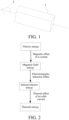
FIG. 1 is a diagram of a battery pulse discharging state of a battery thermal management system according to an embodiment of the present disclosure; and -
FIG. 2 is a process diagram of energy conversion in a heating process of a battery thermal management system according to an embodiment of the present disclosure. - To make the technical problems to be resolved by the present disclosure, technical solutions, and beneficial effects more comprehensible, the following further describes the present disclosure in detail with reference to embodiments and the accompanying drawings. It should be understood that the specific embodiments described herein are merely used to explain the present disclosure but are not intended to limit the present disclosure.
- As shown in
FIG. 1 and FIG. 2 , an embodiment of the present disclosure provides a battery thermal management system, including a battery and a pulse charging and discharging apparatus. The battery includes an electrode core and aconductive housing 1. Theconductive housing 1 is arranged on an outer periphery of the electrode core and is configured to accommodate the electrode core. The pulse charging and discharging apparatus is electrically connected to the battery. The pulse charging and discharging apparatus is configured to perform pulse charging and discharging on the battery to generate a changing magnetic field. The conductive housing is located in the changing magnetic field, and the conductive housing is configured to generate an induced current and heat the electrode core. The pulse charging and discharging apparatus is configured to generate a changing current to charge the battery, or control the battery to discharge based on the changing current. Specifically, the changing current may be an alternating current or a changing direct current. When pulse charging and discharging is performed on the battery, a current flowing through the electrode core is the changing current, and the electrode core generates the changing magnetic field, so that theconductive housing 1 located in the changing magnetic field can generate the induced current, to generate heat to heat the electrode core. Specifically, theconductive housing 1 needs to implement, based on satisfying requirements such as a strength and sealing performance required by the battery, a function of generating eddy current heating by electromagnetic induction in a changing magnetic field when pulse discharging is performed on the battery. - In this embodiment, the changing magnetic field is generated when pulse charging and discharging is performed on the battery. The changing magnetic field causes the
conductive housing 1 located in the magnetic field to generate an induction electromotive force and the induced current. The induced current generated by theconductive housing 1 forms an eddy current effect, generates thermal energy, and starts to heat the electrode core of the battery. Theconductive housing 1 is used as a heating component, so that internal space of the battery pack and the battery is not occupied additionally. In addition, theconductive housing 1 is arranged on the outer periphery of the electrode core, and a heat transfer area is large, so that heat conduction efficiency is improved. When heating is started, theconductive housing 1 can effectively heat a position at which a temperature of the electrode core is the lowest. In addition, a heating power of the battery can be freely adjusted by controlling a pulse charging/discharging frequency and a pulse charging/discharging current magnitude of the pulse charging and discharging apparatus. When theconductive housing 1 heats the electrode core of the battery, the battery has a small impact on another external system (another battery, a pack body, a module structural member, and electrical and thermal management systems). First, due to an eddy current phenomenon generated by the conductive housing, a heating effect on a side that is close to the electrode core is better than a heating effect on a side that is away from the electrode core. Therefore, the battery thermal management system disclosed in the present disclosure can further reduce the impact of heating the battery on the other batteries and make the heating more concentrated. In addition, for a single battery core, when the alternating current is applied to the battery, eddy current heating can be performed, and assisted heating of the single battery core can be further performed due to application of the alternating current. In this way, the heating effect is more obvious. - Specifically, in a charging/discharging process of the battery, a current path inside the electrode core may be simplified to a
current direction 2 that is perpendicular to a cross section of the battery housing. When a current I represented by thecurrent direction 2 changes, a changing magnetic field is generated. - Specifically, basic equations for an electromagnetic induction problem are Maxwell's equations. The Maxwell's equations include Gauss's law for an electric field, circulation law for the electric field, Gauss's law for a magnetic field, and Ampere circuital law. A mathematical expression is as follows:

- In the formula,
-
D is an electrical displacement, and a unit ofD is C/m; - ρ is a charge density, and a unit of ρ is C/m3;
- q is a charge, and a unit of q is C;
-
E is an electric field strength, and a unit ofE is V/m; -
B is a magnetic induction strength, and a unit ofB is A/m; -
H is a magnetic field strength, and a unit ofH is A/m; and -
j is a current density, and a unit ofj is A/m2. - The electromagnetic induction heating in this embodiment is a quasi-stationary electromagnetic field, whose frequency is much lower than a frequency of a radio high frequency electromagnetic field and a frequency of an optical high frequency electromagnetic field, so that in the equations, ∂/∂t is much less than the current density, and a displacement current density is ignored. Therefore, the Maxwell's equations are transformed into a differential form, and a simplified formula is as follows:

- In the formula,
- ∇• is a divergence of a corresponding vector; and
- ∇× is a curl of the corresponding vector.
- According to Biot-Savart Law, a corresponding electric field generates a magnetic field:

- In the formula,
-


- µ0 is a permeability of vacuum (4π×10^(-7)N/A2).
- A relationship between a total current density
j , a source current densityj s, namely, a pulse current density applied by the pulse charging and discharging apparatus to the battery, an eddy current densityj e, and the magnetic induction strengthB is as follows:

- For convenience of representing an induced eddy current density
j e, a magnetic field vectorA is introduced as an auxiliary quantity for calculating the magnetic induction strengthB . It can be learned from an integral form of Biot-Savart Law (2-3) that a relationship betweenA and

- Formulas (2-4) and (2-5) are combined, and a relationship between the eddy current density
j e and the magnetic field vectorA can be obtained:

- A current density in an eddy current heating area is in a one-to-one correspondence with a heating power at each point in an induction heating process:

- It can be learned from the foregoing formula (2-5) and formula (2-6) that the magnetic field vector
A reflects an influence of an induced source current I on the induced eddy current densityj e. The greater the amplitude of a source current change, the higher the induced current in theconductive housing 1. The higher the frequency f of the source current change, the higher the induced current in the housing. Correspondingly, the higher the induced current in the housing, the higher the eddy current heating power. - For the housing that generates the induced current,


- In the formula, µ is a magnetic permeability of a material of the
conductive housing 1, and a unit of µ is H/m; and
ε is a dielectric constant, and a unit of ε is F/m. - In addition, it can be learned from (2-4) and (2-8) that the higher the magnetic permeability µ of the material of the
conductive housing 1, the greater theB , the higher the induced eddy current densityj e, and the higher the eddy current heating power. It can be learned from (2-7) that the lower the resistivity σ of the material of theconductive housing 1, the higher the eddy current heating power p. - In some embodiments, the pulse discharging frequency applied by the pulse charging and discharging apparatus to the battery is greater than 10 Hz.
- In some embodiments, the pulse discharging frequency applied by the pulse charging and discharging apparatus to the battery ranges from 10 Hz to 10000 Hz. When the pulse discharging frequency is less than 10 Hz, a heat generation power of the
conductive housing 1 is excessively low, and heating efficiency is low. When the pulse discharging frequency is higher than 10000 Hz, costs are excessively high. - In some embodiments, a pulse current I applied by the pulse charging and discharging apparatus to the battery is equal to kA. A is a battery capacity, and a unit of A is Ah; and k is a coefficient, and 0.3≤k≤20. Specifically, the range of the pulse current is applicable to a lithium-ion battery at -10°C. As a temperature of the battery before heating further decreases, a maximum value of k needs to be reduced based on an actual condition. When the value of k is less than 0.3, the pulse current I is relatively low, the heat generation power of the
conductive housing 1 is excessively low, and a heating rate is excessively slow. When the value of k is greater than 20, the lithium-ion battery is difficult to discharge at a low temperature due to high internal resistance and large polarization. - In some embodiments, when a temperature of the
conductive housing 1 ranges from -45°C to 100°C, a ratio of a relative magnetic permeability µr of theconductive housing 1 to the resistivity σ of theconductive housing 1 is 500≤µr/σ≤5×106. A unit of σ is 10-6Ω•m. Specifically, the ratio of the relative magnetic permeability µr of theconductive housing 1 to the resistivity σ of theconductive housing 1 may be any of 500, 1000, 5000, 8000, 30000, 170000, 1×10⁶, 3×10⁶, 5×10⁶, and the like, as long as the ratio of the relative magnetic permeability µr of theconductive housing 1 to the resistivity σ of theconductive housing 1 ranges from 500 to 5×10⁶. A material with a relatively large ratio of the magnetic permeability to the resistivity is selected to make theconductive housing 1, so that the induced current generated by theconductive housing 1 is relatively high, thereby increasing the heating power. When the ratio of the relative magnetic permeability µr to the resistivity σ of the material of theconductive housing 1 is less than 500, in the changing magnetic field generated by pulse charging and discharging performed on the battery, the induced current generated by theconductive housing 1 is excessively low or is basically ignored. Therefore, the eddy current heating power is excessively low or may be ignored or the eddy current heating power and heat dissipation of the battery are canceled out with each other. - The higher the magnetic permeability µ of the material of the conductive housing, the greater the
B , the higher the induced eddy current densityj e, and the higher the eddy current heating power. The lower the resistivity σ of the material of the conductive housing, the higher the eddy current heating power p. Therefore, the resistivity σ of the material of the conductive housing needs to be as low as possible, and the magnetic permeability µ needs to be as high as possible, so that the induced current generated by theconductive housing 1 is relatively high, thereby increasing the heating power. - In some embodiments, the material of the
conductive housing 1 is selected from an iron-based soft magnetic alloy. The iron-based soft magnetic alloy includes one or more of silicon steel, soft magnetic stainless steel, permalloy, low-carbon mild steel, amorphous soft magnetic alloy, and nanocrystalline soft magnetic alloy. At 25°C, a ratio of µr/ρ of common silicon steel ranges from 8000 to 30000; a ratio of µr/ρ of the permalloy ranges from 35000 to 170000; and a ratio of µr/ρ of some types of iron-based nanocrystalline alloys ranges from 0.8×10⁶ to 2×10⁶. - Specifically, in the silicon steel, a content of Si ranges from 0.2% to 5%, and the rest is Fe and a silicon-iron alloy that includes a small amount of other elements (single element mass fraction that is less than or equal to 1%) used to improve material performance.
- In the soft magnetic stainless steel, a content of Cr ranges from 10% to 19%, the content of Si ranges from 0.5% to 3%, and the rest is Fe and a small amount of other elements used to improve the material performance.
- In the permalloy, a content of Ni ranges from 30% to 90%, and the rest is Fe and a small amount of other elements used to improve performance.
- The amorphous soft magnetic alloy is selected from one or more of an iron-based amorphous alloy and an iron-nickel-based amorphous alloy. Specifically, in the iron-based amorphous alloy, Fe accounts for 80% by mass, and Si and B elements account for 20% by mass. In the iron-nickel-based amorphous alloy, Ni accounts for 40% by mass, Fe accounts for 40% by mass, and other metal elements used to improve performance account for 20% by mass.
- The nanocrystalline soft magnetic alloy is selected from the iron-based nanocrystalline alloy. Specifically, the iron-based nanocrystalline alloy mainly includes Fe, with a small amount of Nb, Cu, Si, and B elements added. Heat processing is performed on an amorphous material formed by a rapid solidification process.
- In some embodiments, a thickness of the
conductive housing 1 is T, where 0<T≤δ,

- δ is a skin effect penetration depth, and a unit of δ is mm;
- K0 is a skin effect penetration depth coefficient;
- a unit of σ is Ω•m; and
- f is the pulse discharging frequency, and a unit of f is Hz.
- In the present disclosure, the thickness of the conductive housing is controlled, so that a waste of the material of the conductive housing is reduced, the heating efficiency is improved, and an impact of a cell on another external system (another battery, a pack body, a module structural member, and electrical and thermal management systems) during heating is reduced.
- Specifically, K0 is related to a shape of the housing. Generally, K0 of a cylinder is 50300, and other special shapes have different effects. In this embodiment, a cylindrical battery is used as an example for description.
- In some embodiments, the
conductive housing 1 includes a cover plate and a housing. The electrode core is accommodated in the housing. The cover plate is configured to seal the housing. A thickness of the housing is T. In this embodiment, the thickness of the housing is limited to ensure heating of the battery core, while reducing costs of the battery core, and improving an overall energy density and battery space utilization. - In some embodiments, the battery includes a positive terminal and a negative terminal. The positive terminal and the negative terminal are separately arranged at two ends of the
conductive housing 1 and are electrically connected to the electrode core. It should be noted herein that, the positive terminal and the negative terminal may alternatively be arranged side by side at one end of theconductive housing 1. - According to another aspect, an embodiment of the present disclosure further provides a battery pack, including the battery thermal management system according to any one of the foregoing embodiments. For the battery pack, because the battery cores are connected in series, connected in parallel, or the like, the battery pack only needs to apply a changing current to a total positive pole and a total negative pole to implement self-heating of all the battery cores, and performs heating relative to external components. In this embodiment, heating is more uniform for the battery pack, and each battery core can perform self-heating by using the housing. In addition, a difference in the heating power between batteries at different assembly positions in a battery pack body is small, the thermal management system of the entire battery pack body is concise and direct, and the space utilization is high.
- According to another aspect, an embodiment of the present disclosure further provides a vehicle, including the battery thermal management system according to any one of the foregoing embodiments.
- The present disclosure will be further described below by using embodiments.
- This embodiment is used to describe heating efficiency of the battery thermal management system disclosed in the present disclosure. The battery thermal management system includes a battery and a pulse charging and discharging apparatus. A capacity of the battery is 100 Ah. A pulse charging and discharging frequency applied by the pulse charging and discharging apparatus to the battery is 500 Hz. A pulse current is 500 A. A material of a
conductive housing 1 is silicon steel. A ratio of a relative magnetic permeability µr to a resistivity σ is about 10000. - This embodiment is used to describe heating efficiency of the battery thermal management system disclosed in the present disclosure, and a difference between this embodiment and
Embodiment 1 lies in: A pulse charging and discharging frequency applied by a pulse charging and discharging apparatus to a battery is 1000 Hz. - This embodiment is used to describe heating efficiency of the battery thermal management system disclosed in the present disclosure, and a difference between this embodiment and
Embodiment 1 lies in: A pulse current is 350 A. - This embodiment is used to describe heating efficiency of the battery thermal management system disclosed in the present disclosure, and a difference between this embodiment and
Embodiment 1 lies in: A ratio of a relative magnetic permeability µr to a resistivity σ is about 500. - This embodiment is used to describe heating efficiency of the battery thermal management system disclosed in the present disclosure, and a difference between this embodiment and
Embodiment 1 lies in: A pulse charging and discharging frequency applied by a pulse charging and discharging apparatus to a battery is 7500 Hz. A pulse current is 1500 A. A ratio of a relative magnetic permeability µr to a resistivity σ is about 500. - This comparative embodiment is used to describe heating efficiency of the battery thermal management system disclosed in the present disclosure, and a difference between this embodiment and
Embodiment 1 lies in: A material of a conductive housing is an aluminum alloy material. A ratio of a relative magnetic permeability µr to a resistivity σ is 24. - This comparative embodiment is used to describe heating efficiency of the battery thermal management system disclosed in the present disclosure, and a difference between this embodiment and
Embodiment 1 lies in: A pulse charging and discharging frequency applied by a pulse charging and discharging apparatus to a battery is 7500 Hz. A pulse current is 1500 A. A material of a conductive housing is an aluminum alloy material. A ratio of a relative magnetic permeability µr to a resistivity σ is 24. - Beneficial effects of the present disclosure are further described below through tests.
- Test method: A temperature sampling point is arranged inside a to-be-tested battery, at a center of an electrode core of the battery. When it is ensured that start temperatures are the same and test environments are the same, after heating is performed in a same time period (300s), temperatures at the temperature sampling points in different embodiments/comparative embodiments are recorded. The foregoing process is repeated 10 times, and an average value is taken.
- Heating efficiency of the battery is tested, and analysis results are shown in Table 1.
Table 1 Value of a temperature increase Embodiment 1 23.6 ° C Embodiment 2 28.1 °C Embodiment 3 17.5 °C Embodiment 4 12.5 °C Embodiment 5 22.7 ° C Comparative embodiment 1 12.1 ° C Comparative embodiment 2 16.3 °C - It can be learned from the test results in
Embodiment 1 andComparative embodiment 1 that, the ratio of the relative magnetic permeability of the conductive housing to the resistivity of the conductive housing is excessively low, the heating efficiency is reduced, and heating cannot be effectively implemented. A proper material for the conductive housing is selected, so that heating by the conductive housing on the battery is implemented. It can be learned from the test results inEmbodiment 1 to Embodiment 3 that, the pulse charging and discharging frequency and the pulse current are changed, so that heating effects of the battery are different within the same heating time period. In other words, the heating power of theconductive housing 1 can be freely adjusted and flexibly controlled by controlling the pulse charging and discharging frequency and a magnitude of the pulse current during self-heating of the battery. According toEmbodiment 1, Embodiment 4, and Comparative Example 1, when a value of the ratio of the relative magnetic permeability of the conductive housing to the resistivity of the conductive housing is 500, namely, a lower limit of a preferable range, the conductive housing still has a certain heating effect. However, because the used pulse frequency and pulse current are relatively low, a heating power effect of an induced eddy current of theconductive housing 1 is relatively poor, and contribution to heating of the battery is less than 10%. However, when the pulse charging and discharging frequency and the pulse current increase, it can be learned from Embodiment 5 andComparative embodiment 2 that, when the ratio of the relative magnetic permeability of theconductive housing 1 to the resistivity of theconductive housing 1 is 500, the heating effect of the induced eddy current of theconductive housing 1 is improved. Even if the pulse charging and discharging frequency and the pulse current are increased, a heating effect of a commonly used conductive housing made of an aluminum alloy material is not effectively improved either. - The foregoing descriptions are merely preferred embodiments of the present disclosure, but are not intended to limit the present disclosure. Any modification, equivalent replacement, or improvement made within the spirit and principle of the present disclosure shall fall within the protection scope of the present disclosure.
Claims (10)
- A battery thermal management system, comprising a battery and a pulse charging and discharging apparatus, the battery comprising an electrode core and a conductive housing, the conductive housing being arranged on an outer periphery of the electrode core, and the pulse charging and discharging apparatus being electrically connected to the battery, wherein the pulse charging and discharging apparatus is configured to perform pulse charging and discharging on the battery to generate a changing magnetic field, the conductive housing is located in the changing magnetic field, and the conductive housing is configured to generate an induced current and heat the electrode core.
- The battery thermal management system according to claim 1, wherein a pulse charging and discharging frequency applied by the pulse charging and discharging apparatus to the battery is greater than 10 Hz.
- The battery thermal management system according to claim 1 or 2, wherein a pulse current I applied by the pulse charging and discharging apparatus to the battery is equal to kA, wherein A is a battery capacity, and a unit of A is Ah; and k is a coefficient, 0.3≤k≤20, and a unit of I is A.
- The battery thermal management system according to any one of claims 1 to 3, wherein a ratio of a relative magnetic permeability µ r of the conductive housing to a resistivity σ of the conductive housing is 500≤µr/σ≤5×106, wherein a unit of σ is 10-6Ω•m.
- The battery thermal management system according to claim 4, wherein a material of the conductive housing is selected from an iron-based soft magnetic alloy, and the iron-based soft magnetic alloy comprises one or more of silicon steel, soft magnetic stainless steel, permalloy, low-carbon mild steel, amorphous soft magnetic alloy, and nanocrystalline soft magnetic alloy.
- The battery thermal management system according to any one of claims 1 to 5, wherein a thickness of the conductive housing is T, wherein 0<T≤δ,
 δ is a skin effect penetration depth, and a unit of δ is mm;K0 is a skin effect penetration depth coefficient;a unit of σ is Ω•m;f is the pulse charging and discharging frequency, and a unit of f is Hz; andµr is the relative magnetic permeability of the conductive housing.
 - The battery thermal management system according to claim 6, wherein the conductive housing comprises a cover plate and a housing, the electrode core is accommodated in the housing, the cover plate is configured to seal the housing, and a thickness of the housing is T.
- The battery thermal management system according to any one of claims 1 to 7, wherein the battery comprises a positive terminal and a negative terminal, and the positive terminal and the negative terminal are separately arranged at two ends of the conductive housing and are electrically connected to the electrode core.
- A battery pack, comprising the battery thermal management system according to any one of claims 1 to 8.
- A vehicle, comprising the battery thermal management system according to any one of claims 1 to 8.
Applications Claiming Priority (2)
| Application Number | Priority Date | Filing Date | Title |
|---|---|---|---|
| CN202211189986.2A CN117832688A (en) | 2022-09-28 | 2022-09-28 | Battery thermal management system, battery pack and vehicle |
| PCT/CN2023/103968 WO2024066577A1 (en) | 2022-09-28 | 2023-06-29 | Battery thermal management system, battery pack and vehicle |
Publications (2)
| Publication Number | Publication Date |
|---|---|
| EP4560790A1 true EP4560790A1 (en) | 2025-05-28 |
| EP4560790A4 EP4560790A4 (en) | 2025-10-29 |
Family
ID=90475930
Family Applications (1)
| Application Number | Title | Priority Date | Filing Date |
|---|---|---|---|
| EP23869825.2A Pending EP4560790A4 (en) | 2022-09-28 | 2023-06-29 | BATTERY HEAT MANAGEMENT SYSTEM, BATTERY PACK AND VEHICLE |
Country Status (4)
| Country | Link |
|---|---|
| US (1) | US20250226482A1 (en) |
| EP (1) | EP4560790A4 (en) |
| CN (1) | CN117832688A (en) |
| WO (1) | WO2024066577A1 (en) |
Family Cites Families (9)
| Publication number | Priority date | Publication date | Assignee | Title |
|---|---|---|---|---|
| JP2010160932A (en) * | 2009-01-07 | 2010-07-22 | Mitsubishi Motors Corp | Heating device of storage battery |
| DE102012210032A1 (en) * | 2012-06-14 | 2013-12-19 | Robert Bosch Gmbh | Heatable battery device for heating battery cells in automotive region, has metallic films in which eddy current is induced in battery cell by alternating field produced by coil, for heating one of metallic devices by alternating field |
| CN204596904U (en) * | 2015-04-10 | 2015-08-26 | 西安中科新能源科技有限公司 | A kind of lithium battery group with heater |
| WO2019245953A1 (en) * | 2018-06-18 | 2019-12-26 | Milwaukee Electric Tool Corporation | Inductive heating of batteries for charging |
| CN110311069B (en) * | 2019-05-10 | 2021-11-26 | 郑州宇光复合材料有限公司 | Preparation method of new energy power battery pack |
| CN213343218U (en) * | 2020-09-11 | 2021-06-01 | Oppo广东移动通信有限公司 | Circuit structure, battery and electronic equipment |
| CN215451553U (en) * | 2021-04-30 | 2022-01-07 | 比亚迪股份有限公司 | Battery thermal management system and vehicle |
| CN113381078A (en) * | 2021-06-08 | 2021-09-10 | 歌尔科技有限公司 | Winding type battery and TWS Bluetooth headset |
| CN114475362B (en) * | 2021-12-02 | 2024-06-14 | 北京新能源汽车股份有限公司 | Electric vehicle and drive control system thereof |
-
2022
- 2022-09-28 CN CN202211189986.2A patent/CN117832688A/en active Pending
-
2023
- 2023-06-29 WO PCT/CN2023/103968 patent/WO2024066577A1/en not_active Ceased
- 2023-06-29 EP EP23869825.2A patent/EP4560790A4/en active Pending
-
2025
- 2025-03-28 US US19/093,558 patent/US20250226482A1/en active Pending
Also Published As
| Publication number | Publication date |
|---|---|
| CN117832688A (en) | 2024-04-05 |
| US20250226482A1 (en) | 2025-07-10 |
| EP4560790A4 (en) | 2025-10-29 |
| WO2024066577A1 (en) | 2024-04-04 |
Similar Documents
| Publication | Publication Date | Title |
|---|---|---|
| He et al. | A 3D electrochemical-thermal coupled model for electrochemical and thermal analysis of pouch-type lithium-ion batteries | |
| US11313910B2 (en) | Anomaly detection system and anomaly detection method for a secondary battery | |
| US7928690B2 (en) | Method and system for determining a state of charge of a battery | |
| EP4071885B1 (en) | Battery charging method, controller, battery management system, battery, and electric apparatus | |
| US9513338B2 (en) | Method and system for determining a state of charge of a battery | |
| CN106154172B (en) | The quantitative estimation method of lithium-ion-power cell internal short-circuit degree | |
| US9914366B2 (en) | System and method to determine the state of charge of a battery using magnetostriction to detect magnetic response of battery material | |
| Nelson et al. | Design modeling of lithium-ion battery performance | |
| EP3957512B1 (en) | Method and device for controlling permanent magnet motor, power system, and electric vehicle | |
| US20140111145A1 (en) | Charging control apparatus and charging control method for secondary battery | |
| EP2538486A1 (en) | Device for preventing deterioration in storage ability and restoration thereof by electrical processing of lead-acid storage battery | |
| CN103149534A (en) | Magnetic sensor transformer for determining state of charge for iron phosphate lithium ion batteries | |
| KR20210110635A (en) | How to Improve Electrochemical Cell Performance | |
| US11837704B2 (en) | Electrochemical devices including internal eddy current heating | |
| US20170285107A1 (en) | Battery state of charge estimator | |
| Wu et al. | Preheating strategy of variable‐frequency pulse for lithium battery in cold weather | |
| US20250226482A1 (en) | Battery thermal management system, battery pack and vehicle | |
| Renyuan et al. | Resultant magnetic fields due to both windings and heavy current leads in large power transformers | |
| CN113097585A (en) | Lithium battery charging and discharging method | |
| EP4579931A1 (en) | Cathode sheet, anode sheet, battery cell, battery, and electrical device | |
| KR100603986B1 (en) | Battery pack for wireless charge | |
| Albrecht et al. | Investigation of supercapacitors as energy source for compact inductive pulsed-power generators | |
| Wang et al. | Thermal management and phase change heat transfer characteristics of LiFePO4 batteries by cooling phase change materials | |
| CN224036455U (en) | Battery heating circuit, battery thermal management system and vehicle | |
| CN223598914U (en) | Collision-proof vehicle battery |
Legal Events
| Date | Code | Title | Description |
|---|---|---|---|
| STAA | Information on the status of an ep patent application or granted ep patent |
Free format text: STATUS: THE INTERNATIONAL PUBLICATION HAS BEEN MADE |
|
| PUAI | Public reference made under article 153(3) epc to a published international application that has entered the european phase |
Free format text: ORIGINAL CODE: 0009012 |
|
| STAA | Information on the status of an ep patent application or granted ep patent |
Free format text: STATUS: REQUEST FOR EXAMINATION WAS MADE |
|
| 17P | Request for examination filed |
Effective date: 20250220 |
|
| AK | Designated contracting states |
Kind code of ref document: A1 Designated state(s): AL AT BE BG CH CY CZ DE DK EE ES FI FR GB GR HR HU IE IS IT LI LT LU LV MC ME MK MT NL NO PL PT RO RS SE SI SK SM TR |
|
| A4 | Supplementary search report drawn up and despatched |
Effective date: 20250930 |
|
| RIC1 | Information provided on ipc code assigned before grant |
Ipc: H01M 10/615 20140101AFI20250924BHEP Ipc: H01M 10/657 20140101ALI20250924BHEP Ipc: H01M 10/651 20140101ALI20250924BHEP Ipc: B60L 58/27 20190101ALI20250924BHEP Ipc: B60L 50/64 20190101ALI20250924BHEP Ipc: H01M 10/46 20060101ALI20250924BHEP Ipc: H01M 10/625 20140101ALI20250924BHEP Ipc: H01M 10/637 20140101ALI20250924BHEP Ipc: H01M 50/119 20210101ALI20250924BHEP |
|
| DAV | Request for validation of the european patent (deleted) | ||
| DAX | Request for extension of the european patent (deleted) |