EP4560785A1 - Battery pack - Google Patents
Battery pack Download PDFInfo
- Publication number
- EP4560785A1 EP4560785A1 EP24213096.1A EP24213096A EP4560785A1 EP 4560785 A1 EP4560785 A1 EP 4560785A1 EP 24213096 A EP24213096 A EP 24213096A EP 4560785 A1 EP4560785 A1 EP 4560785A1
- Authority
- EP
- European Patent Office
- Prior art keywords
- holder
- battery
- battery cells
- battery cell
- holder portion
- Prior art date
- Legal status (The legal status is an assumption and is not a legal conclusion. Google has not performed a legal analysis and makes no representation as to the accuracy of the status listed.)
- Pending
Links
Images




Classifications
-
- H—ELECTRICITY
- H01—ELECTRIC ELEMENTS
- H01M—PROCESSES OR MEANS, e.g. BATTERIES, FOR THE DIRECT CONVERSION OF CHEMICAL ENERGY INTO ELECTRICAL ENERGY
- H01M10/00—Secondary cells; Manufacture thereof
- H01M10/60—Heating or cooling; Temperature control
- H01M10/65—Means for temperature control structurally associated with the cells
- H01M10/653—Means for temperature control structurally associated with the cells characterised by electrically insulating or thermally conductive materials
-
- H—ELECTRICITY
- H01—ELECTRIC ELEMENTS
- H01M—PROCESSES OR MEANS, e.g. BATTERIES, FOR THE DIRECT CONVERSION OF CHEMICAL ENERGY INTO ELECTRICAL ENERGY
- H01M50/00—Constructional details or processes of manufacture of the non-active parts of electrochemical cells other than fuel cells, e.g. hybrid cells
- H01M50/20—Mountings; Secondary casings or frames; Racks, modules or packs; Suspension devices; Shock absorbers; Transport or carrying devices; Holders
- H01M50/258—Modular batteries; Casings provided with means for assembling
-
- H—ELECTRICITY
- H01—ELECTRIC ELEMENTS
- H01M—PROCESSES OR MEANS, e.g. BATTERIES, FOR THE DIRECT CONVERSION OF CHEMICAL ENERGY INTO ELECTRICAL ENERGY
- H01M10/00—Secondary cells; Manufacture thereof
- H01M10/60—Heating or cooling; Temperature control
- H01M10/61—Types of temperature control
- H01M10/613—Cooling or keeping cold
-
- H—ELECTRICITY
- H01—ELECTRIC ELEMENTS
- H01M—PROCESSES OR MEANS, e.g. BATTERIES, FOR THE DIRECT CONVERSION OF CHEMICAL ENERGY INTO ELECTRICAL ENERGY
- H01M10/00—Secondary cells; Manufacture thereof
- H01M10/60—Heating or cooling; Temperature control
- H01M10/64—Heating or cooling; Temperature control characterised by the shape of the cells
- H01M10/643—Cylindrical cells
-
- H—ELECTRICITY
- H01—ELECTRIC ELEMENTS
- H01M—PROCESSES OR MEANS, e.g. BATTERIES, FOR THE DIRECT CONVERSION OF CHEMICAL ENERGY INTO ELECTRICAL ENERGY
- H01M10/00—Secondary cells; Manufacture thereof
- H01M10/60—Heating or cooling; Temperature control
- H01M10/65—Means for temperature control structurally associated with the cells
- H01M10/655—Solid structures for heat exchange or heat conduction
-
- H—ELECTRICITY
- H01—ELECTRIC ELEMENTS
- H01M—PROCESSES OR MEANS, e.g. BATTERIES, FOR THE DIRECT CONVERSION OF CHEMICAL ENERGY INTO ELECTRICAL ENERGY
- H01M10/00—Secondary cells; Manufacture thereof
- H01M10/60—Heating or cooling; Temperature control
- H01M10/65—Means for temperature control structurally associated with the cells
- H01M10/655—Solid structures for heat exchange or heat conduction
- H01M10/6554—Rods or plates
-
- H—ELECTRICITY
- H01—ELECTRIC ELEMENTS
- H01M—PROCESSES OR MEANS, e.g. BATTERIES, FOR THE DIRECT CONVERSION OF CHEMICAL ENERGY INTO ELECTRICAL ENERGY
- H01M50/00—Constructional details or processes of manufacture of the non-active parts of electrochemical cells other than fuel cells, e.g. hybrid cells
- H01M50/20—Mountings; Secondary casings or frames; Racks, modules or packs; Suspension devices; Shock absorbers; Transport or carrying devices; Holders
- H01M50/204—Racks, modules or packs for multiple batteries or multiple cells
-
- H—ELECTRICITY
- H01—ELECTRIC ELEMENTS
- H01M—PROCESSES OR MEANS, e.g. BATTERIES, FOR THE DIRECT CONVERSION OF CHEMICAL ENERGY INTO ELECTRICAL ENERGY
- H01M50/00—Constructional details or processes of manufacture of the non-active parts of electrochemical cells other than fuel cells, e.g. hybrid cells
- H01M50/20—Mountings; Secondary casings or frames; Racks, modules or packs; Suspension devices; Shock absorbers; Transport or carrying devices; Holders
- H01M50/204—Racks, modules or packs for multiple batteries or multiple cells
- H01M50/207—Racks, modules or packs for multiple batteries or multiple cells characterised by their shape
- H01M50/213—Racks, modules or packs for multiple batteries or multiple cells characterised by their shape adapted for cells having curved cross-section, e.g. round or elliptic
-
- H—ELECTRICITY
- H01—ELECTRIC ELEMENTS
- H01M—PROCESSES OR MEANS, e.g. BATTERIES, FOR THE DIRECT CONVERSION OF CHEMICAL ENERGY INTO ELECTRICAL ENERGY
- H01M50/00—Constructional details or processes of manufacture of the non-active parts of electrochemical cells other than fuel cells, e.g. hybrid cells
- H01M50/20—Mountings; Secondary casings or frames; Racks, modules or packs; Suspension devices; Shock absorbers; Transport or carrying devices; Holders
- H01M50/244—Secondary casings; Racks; Suspension devices; Carrying devices; Holders characterised by their mounting method
-
- H—ELECTRICITY
- H01—ELECTRIC ELEMENTS
- H01M—PROCESSES OR MEANS, e.g. BATTERIES, FOR THE DIRECT CONVERSION OF CHEMICAL ENERGY INTO ELECTRICAL ENERGY
- H01M50/00—Constructional details or processes of manufacture of the non-active parts of electrochemical cells other than fuel cells, e.g. hybrid cells
- H01M50/20—Mountings; Secondary casings or frames; Racks, modules or packs; Suspension devices; Shock absorbers; Transport or carrying devices; Holders
- H01M50/262—Mountings; Secondary casings or frames; Racks, modules or packs; Suspension devices; Shock absorbers; Transport or carrying devices; Holders with fastening means, e.g. locks
- H01M50/264—Mountings; Secondary casings or frames; Racks, modules or packs; Suspension devices; Shock absorbers; Transport or carrying devices; Holders with fastening means, e.g. locks for cells or batteries, e.g. straps, tie rods or peripheral frames
-
- H—ELECTRICITY
- H01—ELECTRIC ELEMENTS
- H01M—PROCESSES OR MEANS, e.g. BATTERIES, FOR THE DIRECT CONVERSION OF CHEMICAL ENERGY INTO ELECTRICAL ENERGY
- H01M50/00—Constructional details or processes of manufacture of the non-active parts of electrochemical cells other than fuel cells, e.g. hybrid cells
- H01M50/20—Mountings; Secondary casings or frames; Racks, modules or packs; Suspension devices; Shock absorbers; Transport or carrying devices; Holders
- H01M50/289—Mountings; Secondary casings or frames; Racks, modules or packs; Suspension devices; Shock absorbers; Transport or carrying devices; Holders characterised by spacing elements or positioning means within frames, racks or packs
- H01M50/291—Mountings; Secondary casings or frames; Racks, modules or packs; Suspension devices; Shock absorbers; Transport or carrying devices; Holders characterised by spacing elements or positioning means within frames, racks or packs characterised by their shape
-
- H—ELECTRICITY
- H01—ELECTRIC ELEMENTS
- H01M—PROCESSES OR MEANS, e.g. BATTERIES, FOR THE DIRECT CONVERSION OF CHEMICAL ENERGY INTO ELECTRICAL ENERGY
- H01M50/00—Constructional details or processes of manufacture of the non-active parts of electrochemical cells other than fuel cells, e.g. hybrid cells
- H01M50/50—Current conducting connections for cells or batteries
- H01M50/502—Interconnectors for connecting terminals of adjacent batteries; Interconnectors for connecting cells outside a battery casing
-
- Y—GENERAL TAGGING OF NEW TECHNOLOGICAL DEVELOPMENTS; GENERAL TAGGING OF CROSS-SECTIONAL TECHNOLOGIES SPANNING OVER SEVERAL SECTIONS OF THE IPC; TECHNICAL SUBJECTS COVERED BY FORMER USPC CROSS-REFERENCE ART COLLECTIONS [XRACs] AND DIGESTS
- Y02—TECHNOLOGIES OR APPLICATIONS FOR MITIGATION OR ADAPTATION AGAINST CLIMATE CHANGE
- Y02E—REDUCTION OF GREENHOUSE GAS [GHG] EMISSIONS, RELATED TO ENERGY GENERATION, TRANSMISSION OR DISTRIBUTION
- Y02E60/00—Enabling technologies; Technologies with a potential or indirect contribution to GHG emissions mitigation
- Y02E60/10—Energy storage using batteries
Definitions
- One or more embodiments relate to a battery pack.
- a secondary battery can be charged and discharged, unlike a primary battery that cannot be recharged.
- Secondary batteries are used as energy sources for mobile devices, electric vehicles, hybrid vehicles, electric bicycles, uninterruptible power supplies, etc.
- the secondary batteries may be used in the form of a single battery or in the form of a module in which multiple battery cells are connected and grouped into one unit.
- Small mobile devices such as mobile phones may operate for a certain amount of time based on the output and capacity of a single battery, whereas for devices requiring long-term driving and high-power operations, such as electric vehicles and hybrid vehicles that consume a lot of power, a module type including a plurality of batteries may be utilized due to output and capacity issues.
- the output voltage or output current may be increased with the number of built-in batteries.
- One or more embodiments provide a battery pack achieving a fixing force of a battery cell through a structure for fixing a bottom portion and a side portion of the battery cell together.
- One or more embodiments provide a battery pack that achieves excellent heat-dissipating performance due to a structure in which an opening portion is formed in a holder portion fixing a battery cell.
- a battery pack includes battery cells, a housing accommodating the battery cells, a bus bar electrically connecting the battery cells, a holder portion fixing a bottom portion and a side portion of the battery cells, a cooling unit under the holder portion to cool the battery cells, and a filling portion contacting a surface portion of the battery cells between the plurality of battery cells and the cooling unit.
- the filling portion covers at least part of the bottom portion of the battery cells and at least part of the side portion of the battery cells.
- the holder portion may include an opening portion through which a part of the bottom portion and a part of the side portion of the battery cells are exposed, and the filling portion may cover the part of the bottom portion and the part of the side portion of the battery cells exposed by the opening portion.
- a sheet portion may be between the filling portion and the cooling unit.
- the second holder portion may have a ring shape and a first opening portion on the bottom portion of the battery cell such that the battery cell may be exposed to outside of the holder portion through the first opening portion.
- a first filling portion covering a part of the bottom portion of the battery cell may be accommodated in the first opening portion.
- the third holder portion may include 3rd-1 holder portions arranged circumferentially around the second holder portion and extending radially outward from the second holder portion on the bottom portion of the battery cell, and a second opening portion between an outer side of the second holder portion and two adjacent 3rd-1 holder portions among the 3rd-1 holder portions on the bottom portion of the battery cell such that the battery cell may be exposed to outside of the holder portion through the second opening portion.
- a second filling portion covering part of the bottom portion of the battery cell may be accommodated in the second opening portion.
- the first holder portion may be spaced apart from the bottom portion of the battery cell
- the third holder portion may include 3rd-2 holder portions spaced apart from each other in a circumferential direction of the side portion of the battery cell and a third opening portion between the first holder portion and the bottom portion of the battery cell and between two adjacent 3rd-2 holder portions among the 3rd-2 holder portions on the side portion of the battery cell such that the battery cell may be exposed to outside of the holder portion through the third opening portion.
- a third filling portion covering part of the side portion of the battery cell may be accommodated in the third opening portion.
- the third holder portion may include 3rd-1 holder portions arranged circumferentially around the second holder portion and may extend radially from the second holder portion on the bottom portion of the battery cell, and 3rd-2 holder portions spaced apart from each other in a circumferential direction of the side portion of the battery cell.
- the 3rd-1 holder portions and the 3rd-2 holder portions may be integral.
- an x-axis, a y-axis, and a z-axis are not limited to three axes on an orthogonal coordinate system, and may be interpreted in a broad sense including them.
- the x-axis, the y-axis, and the z-axis may be orthogonal to each other, but may also refer to different directions that are not orthogonal to each other.
- FIGS. 1 to 8 a battery pack according to embodiments of the present disclosure will be described with reference to FIGS. 1 to 8 .
- FIG. 1 is a partial exploded perspective view of a battery pack according to embodiments of the present disclosure.
- FIG. 2 is a partial plan view of a battery pack according to embodiments of the present disclosure.
- FIG. 3 is an exploded perspective view of a plurality of battery cells and a holder portion, according to embodiments of the present disclosure.
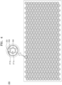
- FIG. 4 is a plan view of a holder portion according to embodiments of the present disclosure.
- FIG. 5 is a cross-sectional view taken along A-A of FIG. 3 .
- FIG. 6 is a view of a battery pack viewed in a direction B of FIG. 3 .
- FIG. 7 is view of a battery pack viewed in a direction of FIG. 3 , including a filling portion.
- FIG. 8 is an exploded perspective view of a part of a holder portion into which a battery cell is inserted, together with a filling portion.
- a battery pack includes a plurality of battery cells 300, a housing 100 accommodating the plurality of battery cells 300, a bus bar 400 electrically connecting the plurality of battery cells 300, a holder portion 200 fixing a bottom portion and a side portion of the plurality of battery cells 300, a cooling unit 110 under the holder portion 200 and configured to cool the plurality of battery cells 300, and a filling portion 210 configured to contact a surface portion of the plurality of battery cells 300 between the plurality of battery cells 300 and the cooling unit 110.
- the filling portion 210 covers at least a part of the bottom portion of the plurality of battery cells 300 and at least a part of the side portion of the plurality of battery cells 300.
- the plurality of battery cells 300 may be arranged in a plurality of columns and a plurality of rows inside the housing 100, and the plurality of battery cells 300 arranged in the plurality of columns and the plurality of rows may be alternately arranged (e.g., staggered).
- the holder portion 200 may be on a lower portion of the plurality of battery cells 300 to fix the plurality of battery cells 300.
- the holder portion 200 may be configured to accommodate the plurality of battery cells 300 at the same intervals (or substantially the same intervals) such that each of the plurality of battery cells 300 may be fixed on the holder portion 200 with a constant interval (or substantially a constant interval) with adjacent battery cells 300.
- the filling portion 210 (e.g., the thermal glue of the adhesive material) may be or include a material having electrical insulation, and the holder portion 200 and the sheet portion 120 may also be or include a material having electrical insulation, such that electrical insulation between the plurality of battery cells 300 and the housing 100 including the cooling unit 110 may be triple-protected.
- the second holder portion 202 may have a ring shape (i.e., an annular shape) in the center of the bottom portion of the cylindrical battery cell to fix the bottom portion of the battery cell.
- a battery cell mounted on the second holder portion 202 may not be able to move in a downward direction due to the second holder portion 202.
- the first holder portion 201, the second holder portion 202, and the third holder portion 203 may be integral. In this way, the rigidity of the holder portion 200 may be achieved, thereby securing a fixing force with respect to the plurality of battery cells 300.
- a first opening portion 211a may be included in the second holder portion 202 (e.g., the first opening portion 211a may be formed by the ringshaped second holder portion 202), and the battery cell may be exposed to outside of the holder portion 200 through the first opening portion 211a.
- a first filling portion 210a covering a part of the bottom portion 301 of the battery cell may be accommodated in the first opening portion 211a.
- the third holder portion 203 may also include a plurality of 3rd-1 holder portions 203a arranged circumferentially around and extending radially outward from the second holder portion 202 on the bottom portion 301 of the battery cell.
- a second opening portion 211b may be formed between an outer portion of the second holder portion 202 and two adjacent 3rd-1 holder portions 203a among the plurality of 3rd-1 holder portions 203a, and the battery cell may be exposed to outside of the holder portion 203a through the second opening portion 211b.
- a second filling portion 210b covering a part of the bottom portion 301 of the battery cell may be accommodated in the second opening portion 211b.
- three opening portions 211c may be formed between the first holder portion 201 and the bottom portion 301 of the battery cell and between two adjacent 3rd-2 holder portions 203b among the plurality of 3rd-2 holder portions 203b, and the battery cell may be exposed to outside of the holder portion 200 through the third opening portion 211c.
- a third filling portion 210c covering a part of the side portion 302 of the battery cell may be accommodated in the third opening portion 211c.
- heat generated on the side portion 302 of the plurality of battery cells 300 may be dissipated to outside of the plurality of battery cells 300 through the third filling portion 210c on the side portion 302 of the plurality of battery cells 300.
- the 3rd-1 holder portions 203a and the 3rd-2 holder portions 203b forming the third holder portion 203 may be integral to protect the corner portion of the plurality of battery cells 300, and the filling portion 210 may be accommodated in the opening portion formed by the 3rd-1 holder portion 203a and the 3rd-2 holder portion 203b, thereby achieving heat-dissipating performance for heat generated on the corner portion of the plurality of battery cells 300 and achieving insulation for the corner portion of the plurality of battery cells 300.
- the battery pack according to embodiments of the present disclosure may achieve heat-dissipating performance through a structure in which an opening portion is formed on a holder portion fixing a battery cell.
- the battery pack according to embodiments of the present disclosure may achieve a fixing force of a battery cell through a structure for fixing a bottom portion and a side portion of the battery cell together.
Landscapes
- Chemical & Material Sciences (AREA)
- Chemical Kinetics & Catalysis (AREA)
- Electrochemistry (AREA)
- General Chemical & Material Sciences (AREA)
- Engineering & Computer Science (AREA)
- Manufacturing & Machinery (AREA)
- Battery Mounting, Suspending (AREA)
- Secondary Cells (AREA)
- Connection Of Batteries Or Terminals (AREA)
Abstract
A battery pack (10) includes battery cells (300), a housing (100) accommodating the battery cells, a bus bar (400) electrically connecting the battery cells, (300) a holder portion (200) fixing a bottom portion and a side portion of the battery cells, a cooling unit (110) under the holder portion (200) to cool the battery cells, and a filling portion (210) contacting a surface portion of the battery cells between the plurality of battery cells and the cooling unit. The filling portion (210) covers at least part of the bottom portion (301) of the battery cells and at least part of the side portion (302) of the battery cells.


Description
- One or more embodiments relate to a battery pack.
- Generally, a secondary battery can be charged and discharged, unlike a primary battery that cannot be recharged. Secondary batteries are used as energy sources for mobile devices, electric vehicles, hybrid vehicles, electric bicycles, uninterruptible power supplies, etc. Depending on the type of external device that the secondary batteries are applied to, the secondary batteries may be used in the form of a single battery or in the form of a module in which multiple battery cells are connected and grouped into one unit.
- Small mobile devices such as mobile phones may operate for a certain amount of time based on the output and capacity of a single battery, whereas for devices requiring long-term driving and high-power operations, such as electric vehicles and hybrid vehicles that consume a lot of power, a module type including a plurality of batteries may be utilized due to output and capacity issues. The output voltage or output current may be increased with the number of built-in batteries.
- One or more embodiments provide a battery pack achieving a fixing force of a battery cell through a structure for fixing a bottom portion and a side portion of the battery cell together.
- One or more embodiments provide a battery pack that achieves excellent heat-dissipating performance due to a structure in which an opening portion is formed in a holder portion fixing a battery cell.
- However, these problems are exemplary, and the problems to be solved by the present disclosure are not limited thereto.
- Additional aspects will be set forth in part in the description which follows and, in part, will be apparent from the description, or may be learned by practice of the presented embodiments of the present disclosure.
- According to one or more embodiments, a battery pack includes battery cells, a housing accommodating the battery cells, a bus bar electrically connecting the battery cells, a holder portion fixing a bottom portion and a side portion of the battery cells, a cooling unit under the holder portion to cool the battery cells, and a filling portion contacting a surface portion of the battery cells between the plurality of battery cells and the cooling unit. The filling portion covers at least part of the bottom portion of the battery cells and at least part of the side portion of the battery cells.
- In the battery pack according to embodiments of the present disclosure, the holder portion may include an opening portion through which a part of the bottom portion and a part of the side portion of the battery cells are exposed, and the filling portion may cover the part of the bottom portion and the part of the side portion of the battery cells exposed by the opening portion.
- In the battery pack according to embodiments of the present disclosure, a sheet portion may be between the filling portion and the cooling unit.
- In the battery pack according to embodiments of the present disclosure, the holder portion may include a first holder portion along a circumferential direction of a side portion of a battery cell among the battery cells to fix the side portion of the battery cell, a second holder portion in substantially a center of a bottom portion of the battery cell, and a third holder portion bent along the bottom portion and the side portion and connecting the first holder portion to the second holder portion.
- In the battery pack according to embodiments of the present disclosure, the second holder portion may have a ring shape and a first opening portion on the bottom portion of the battery cell such that the battery cell may be exposed to outside of the holder portion through the first opening portion.
- In the battery pack according to embodiments of the present disclosure, a first filling portion covering a part of the bottom portion of the battery cell may be accommodated in the first opening portion.
- In the battery pack according to embodiments of the present disclosure, the third holder portion may include 3rd-1 holder portions arranged circumferentially around the second holder portion and extending radially outward from the second holder portion on the bottom portion of the battery cell, and a second opening portion between an outer side of the second holder portion and two adjacent 3rd-1 holder portions among the 3rd-1 holder portions on the bottom portion of the battery cell such that the battery cell may be exposed to outside of the holder portion through the second opening portion.
- In the battery pack according to embodiments of the present disclosure, a second filling portion covering part of the bottom portion of the battery cell may be accommodated in the second opening portion.
- In the battery pack according to embodiments of the present disclosure, the first holder portion may be spaced apart from the bottom portion of the battery cell, and the third holder portion may include 3rd-2 holder portions spaced apart from each other in a circumferential direction of the side portion of the battery cell and a third opening portion between the first holder portion and the bottom portion of the battery cell and between two adjacent 3rd-2 holder portions among the 3rd-2 holder portions on the side portion of the battery cell such that the battery cell may be exposed to outside of the holder portion through the third opening portion.
- In the battery pack according to embodiments of the present disclosure, a third filling portion covering part of the side portion of the battery cell may be accommodated in the third opening portion.
- In the battery pack according to embodiments of the present disclosure, the first holder portion, the second holder portion, and the third holder portion may be integral.
- In the battery pack according to embodiments of the present disclosure, the third holder portion may include 3rd-1 holder portions arranged circumferentially around the second holder portion and may extend radially from the second holder portion on the bottom portion of the battery cell, and 3rd-2 holder portions spaced apart from each other in a circumferential direction of the side portion of the battery cell. The 3rd-1 holder portions and the 3rd-2 holder portions may be integral.
- Other aspects, features and advantages than described above will become apparent from the detailed description, claims, and drawings for carrying out the present disclosure below.
- The above and other aspects, features, and advantages of certain embodiments of the present disclosure will be more apparent from the following description taken in conjunction with the accompanying drawings.
-
FIG. 1 is a partial exploded perspective view of a battery pack according to one or more embodiments of the present disclosure; -
FIG. 2 is a partial plan view of a battery pack according to one or more embodiments of the present disclosure; -
FIG. 3 is an exploded perspective view of a plurality of battery cells and a holder portion according to one or more embodiments of the present disclosure; -
FIG. 4 is a plan view of a holder portion according to one or more embodiments of the present disclosure; -
FIG. 5 is a cross-sectional view taken along A-A inFIG. 3 ; -
FIG. 6 is a view of a battery pack viewed in a direction B ofFIG. 3 ; -
FIG. 7 is view of a battery pack viewed in a direction B ofFIG. 3 , including a filling portion, according to one or more embodiments of the present disclosure; and -
FIG. 8 is an exploded perspective view of a part of a holder portion into which a battery cell is inserted, together with a filling portion, according to one or more embodiments of the present disclosure. - Reference will now be made in detail to embodiments, examples of which are illustrated in the accompanying drawings, wherein like reference numerals refer to like elements throughout. In this regard, the present embodiments may have different forms and should not be construed as being limited to the descriptions set forth herein. Accordingly, the embodiments are merely described below, by referring to the figures, to explain aspects of the present description. As used herein, the term "and/or" includes any and all combinations of one or more of the associated listed items.
- The present disclosure may have various modifications thereto and various embodiments, and thus particular embodiments will be illustrated in the drawings and described in detail in a detailed description. To describe the present disclosure, the same component, even when shown in different embodiments, will be denoted by the same reference numeral.
- Hereinafter, embodiments of the present disclosure will be described in detail with reference to the accompanying drawings, and in description with reference to the drawings, the same or corresponding components are given the same reference numerals, and redundant description thereto will be omitted.
- In the following embodiments, the terms such as first, second, etc., have been used to distinguish one component from other components, rather than limiting.
- In the following embodiments, singular forms include plural forms unless apparently indicated otherwise contextually.
- In the following embodiments, the terms "include", "have", or the like, are intended to mean that there are features, or components, described herein, but do not preclude the possibility of adding one or more other features or components.
- In the drawings, the size of components may be exaggerated or reduced for convenience of description. For example, the size and thickness of each component shown in the drawings are shown for convenience of description, and thus the present disclosure is not necessarily limited to the illustration.
- In the following embodiments, an x-axis, a y-axis, and a z-axis are not limited to three axes on an orthogonal coordinate system, and may be interpreted in a broad sense including them. For example, the x-axis, the y-axis, and the z-axis may be orthogonal to each other, but may also refer to different directions that are not orthogonal to each other.
- If certain embodiments may be implemented otherwise, a particular process order may be performed differently from the order described. For example, two processes described in succession may be performed substantially simultaneously, or may be performed in an order reverse to the order described.
- The term used herein is used to describe particular embodiments, and is not intended to limit the present disclosure. Herein, it should be understood that the term "include", "have", or the like used herein is to indicate the presence of features, numbers, steps, operations, components, parts, or a combination thereof described in the specifications, and does not preclude the presence or addition of one or more other features, numbers, steps, operations, components, parts, or a combination thereof.
- Hereinbelow, a battery pack according to embodiments of the present disclosure will be described with reference to
FIGS. 1 to 8 . -
FIG. 1 is a partial exploded perspective view of a battery pack according to embodiments of the present disclosure.FIG. 2 is a partial plan view of a battery pack according to embodiments of the present disclosure.FIG. 3 is an exploded perspective view of a plurality of battery cells and a holder portion, according to embodiments of the present disclosure.FIG. 4 is a plan view of a holder portion according to embodiments of the present disclosure.FIG. 5 is a cross-sectional view taken along A-A ofFIG. 3 .FIG. 6 is a view of a battery pack viewed in a direction B ofFIG. 3 .FIG. 7 is view of a battery pack viewed in a direction ofFIG. 3 , including a filling portion.FIG. 8 is an exploded perspective view of a part of a holder portion into which a battery cell is inserted, together with a filling portion. - Referring to
FIGS. 1 to 8 , a battery pack includes a plurality ofbattery cells 300, ahousing 100 accommodating the plurality ofbattery cells 300, abus bar 400 electrically connecting the plurality ofbattery cells 300, aholder portion 200 fixing a bottom portion and a side portion of the plurality ofbattery cells 300, acooling unit 110 under theholder portion 200 and configured to cool the plurality ofbattery cells 300, and a fillingportion 210 configured to contact a surface portion of the plurality ofbattery cells 300 between the plurality ofbattery cells 300 and thecooling unit 110. The fillingportion 210 covers at least a part of the bottom portion of the plurality ofbattery cells 300 and at least a part of the side portion of the plurality ofbattery cells 300. - The
housing 100 may have a rectangular parallelepiped shape as shown inFIG. 1 . Although thehousing 100 is depicted and described as having the rectangular parallelepiped shape, in one or more embodiments thehousing 100 may have any other suitable shape. An array of the plurality ofbattery cells 300 may be accommodated in an inner space of thehousing 100. The plurality ofbattery cells 300 may be cylindrical secondary batteries. The plurality ofbattery cells 300 may be configured to be repeatedly charged and discharged. - The plurality of
battery cells 300 may be arranged in a plurality of columns and a plurality of rows inside thehousing 100, and the plurality ofbattery cells 300 arranged in the plurality of columns and the plurality of rows may be alternately arranged (e.g., staggered). - The plurality of
battery cells 300 arranged in the plurality of columns and the plurality of rows may be fixed by theholder portion 200 inside thehousing 100. Theholder portion 200 may be on a lower portion of the plurality ofbattery cells 300 to fix the plurality ofbattery cells 300. - The
bus bar 400 may be on an upper portion of the plurality ofbattery cells 300. Thebus bar 400 may be on the upper portion of the plurality ofbattery cells 300 and connected to all of the plurality ofbattery cells 300 to electrically connect the plurality ofbattery cells 300 to each other. - According to one or more embodiments, the
cooling unit 110, which is configured to cool the plurality ofbattery cells 300, may be under theholder portion 200. Thecooling unit 110 may be arranged inside a bottom portion of thehousing 100 under theholder portion 200. A coolant may flow on and/or in thecooling unit 110. By appropriately discharging or reducing heat generated during an operation of the plurality ofbattery cells 300 through thecooling unit 110, a temperature of the battery pack 10 may be controlled. - A
sheet portion 120 may be arranged between the coolingunit 110 and theholder portion 200. Thesheet portion 120 may have insulation. For example, thesheet portion 120 may be a polyethylene terephthalate (PET) sheet having insulation. Electrical insulation between the plurality ofbattery cells 300 and thehousing 100 may be achieved through thesheet portion 120. - The filling
portion 210 may be between the plurality ofbattery cells 300 mounted on theholder portion 200 and thesheet portion 120. In one or more embodiments, the fillingportion 210 may have electrical insulation. For example, the fillingportion 210 may be a thermal glue having electrical insulation. The fillingportion 210 may be an adhesive material that facilitates heat transfer and is cured by heat. Thus, heat-dissipating performances can be increased through above materials. Although in one or more embodiments the fillingportion 210 is described as a thermal glue, in one or more embodiments the fillingportion 210 may be an adhesive material such as a silicon adhesive, etc., having thermal conductivity, although the present disclosure is not limited thereto. - The filling portion 210 (e.g., the thermal glue or the adhesive material) may be on a top surface of the
sheet portion 120 and thus may be accommodated in anopening portion 211 in theholder portion 200 as will be described below. Through filling portion 210 (e.g., the thermal glue having thermal conductivity), heat generated in the plurality ofbattery cells 300 may be transferred to thecooling unit 110. Through filling portion 210 (e.g., the thermal glue having thermal conductivity and electrical insulation), electrical insulation may be achieved between the plurality ofbattery cells 300 and thehousing 100 including thecooling unit 110. - The
holder portion 200 may be on a lower portion of the plurality ofbattery cells 300 to fix the plurality ofbattery cells 300. Theholder portion 200 may be configured to accommodate the plurality ofbattery cells 300 at the same intervals (or substantially the same intervals) such that each of the plurality ofbattery cells 300 may be fixed on theholder portion 200 with a constant interval (or substantially a constant interval) withadjacent battery cells 300. - According to one or more embodiments, the
holder portion 200 may include theopening portion 211 through which a part of the bottom portion and a part of the side portion of the plurality ofbattery cells 300 are exposed, and the fillingportion 210 may cover the part of the bottom portion and the part of the side portion of the plurality ofbattery cells 300 that are exposed by theopening portion 211. - The
holder portion 200 may be configured to fix not only the bottom portion of the plurality ofbattery cells 300 but also the side portion of the plurality ofbattery cells 300 to prevent (or at least mitigate) the plurality ofbattery cells 300 from inadvertently dislodging from theholder portion 200 by fixing the plurality ofbattery cells 300. In this way, it is possible to prevent the plurality ofbattery cells 300 mounted on theholder portion 200 from tilting, thereby maintaining a constant or substantially constant interval between the plurality ofbattery cells 300 and thus achieving mechanical stability of the plurality ofbattery cells 300. - The
opening portion 211 in theholder portion 200 may be on the side portion of the plurality ofbattery cells 300 as well as the bottom portion thereof, and the fillingportion 210 may cover both the bottom portion and the side portion of the plurality ofbattery cells 300, thereby achieving a heat-dissipating function through the side portion of the plurality ofbattery cells 300 and thus further improving heat-dissipating performance for the plurality ofbattery cells 300. - The filling portion 210 (e.g., the thermal glue of the adhesive material) may be or include a material having electrical insulation, and the
holder portion 200 and thesheet portion 120 may also be or include a material having electrical insulation, such that electrical insulation between the plurality ofbattery cells 300 and thehousing 100 including thecooling unit 110 may be triple-protected. - Hereinbelow, a detailed structure of the
holder portion 200 and the fillingportion 210 according to one or more embodiments will be described in more detail. - According to one or more embodiments, the
holder portion 200 may include afirst holder portion 201 extending along a circumferential direction of a side portion of a battery cell among the plurality ofbattery cells 300 to fix the side portion of the battery cell, asecond holder portion 202 in a center of a bottom portion of the battery cell, and athird holder portion 203 bent along the bottom portion and the side portion and connecting thefirst holder portion 201 to thesecond holder portion 202. - The
first holder portion 201 may be formed in a circumferential direction of a side portion of a cylindrical battery cell to fix the side portion of the battery cell. Thus, a battery cell inserted into thefirst holder portion 201 may not be able to move in a side (lateral) direction due to thefirst holder portion 201. - The
second holder portion 202 may have a ring shape (i.e., an annular shape) in the center of the bottom portion of the cylindrical battery cell to fix the bottom portion of the battery cell. Thus, a battery cell mounted on thesecond holder portion 202 may not be able to move in a downward direction due to thesecond holder portion 202. - The
third holder portion 203 may connect thefirst holder portion 201 to thesecond holder portion 202 and may be bent along a corner portion of a battery cell mounted on thefirst holder portion 201 and thesecond holder portion 202. Thethird holder portion 203 may extend radially outward from thesecond holder portion 202. In one or more embodiments, thethird holder portion 203 may include fourthird holder portions 203 arranged circumferentially around thesecond holder portion 202 and extending radially outward from thesecond holder portion 202, but the number ofthird holder portions 203 is not limited thereto. Thethird holder portions 203 may be arranged at regular intervals (or substantially regular intervals) in a circumferential direction around thesecond holder portion 202. - The
first holder portion 201, thesecond holder portion 202, and thethird holder portion 203 may be integral. In this way, the rigidity of theholder portion 200 may be achieved, thereby securing a fixing force with respect to the plurality ofbattery cells 300. - On a
bottom portion 301 of a battery cell, afirst opening portion 211a may be included in the second holder portion 202 (e.g., thefirst opening portion 211a may be formed by the ringshaped second holder portion 202), and the battery cell may be exposed to outside of theholder portion 200 through thefirst opening portion 211a. Afirst filling portion 210a covering a part of thebottom portion 301 of the battery cell may be accommodated in thefirst opening portion 211a. - In this way, heat generated on the
bottom portion 301 of the plurality ofbattery cells 300 may be dissipated to outside of the plurality ofbattery cells 300 through thefirst filling portion 210a on the bottom portion of the plurality ofbattery cells 300. - The
third holder portion 203 may also include a plurality of 3rd-1holder portions 203a arranged circumferentially around and extending radially outward from thesecond holder portion 202 on thebottom portion 301 of the battery cell. - On the
bottom portion 301 of the battery cell, asecond opening portion 211b may be formed between an outer portion of thesecond holder portion 202 and two adjacent 3rd-1holder portions 203a among the plurality of 3rd-1holder portions 203a, and the battery cell may be exposed to outside of theholder portion 203a through thesecond opening portion 211b. Asecond filling portion 210b covering a part of thebottom portion 301 of the battery cell may be accommodated in thesecond opening portion 211b. - In this way, heat generated on the bottom portion and lower corner portion of the plurality of
battery cells 300 may be dissipated to outside of the plurality ofbattery cells 300 through thesecond filling portion 210b arranged on the bottom portion and the corner portion of the plurality ofbattery cells 300. - The
first holder portion 201 may be at a position spaced apart from thebottom portion 301 of the battery cell, and thethird holder portion 203 may include a plurality of 3rd-2holder portions 203b arranged spaced apart from each other in a circumferential direction of theside portion 302 of the battery cell. - On the
side portion 302 of the battery cell, three openingportions 211c may be formed between thefirst holder portion 201 and thebottom portion 301 of the battery cell and between two adjacent 3rd-2holder portions 203b among the plurality of 3rd-2holder portions 203b, and the battery cell may be exposed to outside of theholder portion 200 through thethird opening portion 211c. Athird filling portion 210c covering a part of theside portion 302 of the battery cell may be accommodated in thethird opening portion 211c. - In this way, heat generated on the
side portion 302 of the plurality ofbattery cells 300 may be dissipated to outside of the plurality ofbattery cells 300 through thethird filling portion 210c on theside portion 302 of the plurality ofbattery cells 300. - In one or more embodiments, the 3rd-1
holder portions 203a and the 3rd-2holder portions 203b forming thethird holder portion 203 may be integral to protect the corner portion of the plurality ofbattery cells 300, and the fillingportion 210 may be accommodated in the opening portion formed by the 3rd-1holder portion 203a and the 3rd-2holder portion 203b, thereby achieving heat-dissipating performance for heat generated on the corner portion of the plurality ofbattery cells 300 and achieving insulation for the corner portion of the plurality ofbattery cells 300. - As such, the present disclosure has been described with reference to the embodiments shown in the drawings, but this is merely an example. It would be fully understood by those of ordinary skill in the art that various modifications and other equivalent embodiments are possible from the embodiments. Therefore, the true technical scope of the present disclosure should be defined by the appended claims.
- Specific technical details described in the embodiments are examples, and do not limit the technical scope of the embodiments. In order to briefly and clearly describe the description of the present disclosure, the description of conventional general techniques and configurations may be omitted.
- Connections of lines or connection members between components shown in the drawings are illustrative of functional connections and/or physical or circuit connections, and in practice, may be expressed as alternative or additional various functional connections, physical connections, or circuit connections. In addition, when there is no specific mentioning, such as "essential" or "important", it may not be a necessary component for the application of the present disclosure.
- A designator "the" or similar designators described in the description and the claims may refer to both singular and plural, unless otherwise specifically limited. In addition, when the range is described in the embodiments, the range includes the present disclosure to which an individual value falling within the range is applied (unless stated otherwise), and is the same as the description of an individual value constituting the range in the description of the present disclosure.
- When there is no apparent description of the order of operations constituting the method according to the embodiments or a contrary description thereof, the operations may be performed in an appropriate order.
- However, the present disclosure is not necessarily limited according to the describing order of the operations. The use of all examples or exemplary terms (for example, etc.) in the present disclosure are to simply describe the present disclosure in detail, and unless the range of the present disclosure is not limited by the examples or the exemplary terms unless limited by the claims.
- In addition, it may be understood by those of ordinary skill in the art that various modifications, combinations, and changes may be made according to design conditions and factors within the scope of the appended claims or equivalents thereof.
- The battery pack according to embodiments of the present disclosure may achieve heat-dissipating performance through a structure in which an opening portion is formed on a holder portion fixing a battery cell.
- The battery pack according to embodiments of the present disclosure may achieve a fixing force of a battery cell through a structure for fixing a bottom portion and a side portion of the battery cell together.
- Effects of the present disclosure are not limited to the effects mentioned above, and other effects not mentioned will be clearly understood by those of ordinary skill in the art from the detailed description and description of the claims.
- It should be understood that embodiments described herein should be considered in a descriptive sense only and not for purposes of limitation. Descriptions of features or aspects within each embodiment should typically be considered as available for other similar features or aspects in other embodiments. While one or more embodiments have been described with reference to the figures, it will be understood by those of ordinary skill in the art that various changes in form and details may be made therein without departing from the scope of the present disclosure as defined by the following claims.
Claims (15)
- A battery pack (10) comprising:a plurality of battery cells (300);a housing (100) accommodating the plurality of battery cells (300);a bus bar (400) electrically connecting the plurality of battery cells (300);a holder portion (200) fixing a bottom portion (301) and a side portion (302) of the plurality of battery cells (300);a cooling unit (110) under the holder portion (200) and configured to cool the plurality of battery cells (300); anda filling portion (210) contacting a surface portion of the plurality of battery cells (300) between the plurality of battery cells (300) and the cooling unit (110),wherein the filling portion (210) covers at least part of the bottom portion (301) of the plurality of battery cells (300) and at least part of the side portion (302) of the plurality of battery cells (300).
- The battery pack (10) as claimed in claim 1, wherein the holder portion (200) comprises an opening portion (211) through which a part of the bottom portion (301) and a part of the side portion (302) of the plurality of battery cells (300) are exposed, and wherein the filling portion (210) covers the part of the bottom portion (301) and the part of the side portion (302) of the plurality of battery cells (300) exposed by the opening portion (211).
- The battery pack (10) as claimed in one of the claims 1 to 2, further comprising a sheet portion (120) between the filling portion (210) and the cooling unit (110).
- The battery pack (10) as claimed in claim 3, wherein the filling portion (210) is disposed between the plurality of battery cells (300) fixed on the holder portion (200) and the sheet portion (120).
- The battery pack (10) as claimed in one of the claims 1 to 4, wherein the filling portion (210) is a thermal glue.
- The battery pack (10) as claimed in one of the claims 1 to 4, wherein the filling portion (210) is a cured adhesive for facilitating heat transfer.
- The battery pack (10) as claimed in one of the claims 1 to 6, wherein the holder portion (200) comprises:a first holder portion (201) extending in a circumferential direction of a side portion (302) of a battery cell (300) among the plurality of battery cells (300), the first holder portion (201) fixing the side portion (302) of the battery cell (300);a second holder portion (202) in a center of a bottom portion (301) of the battery cell (300) among the plurality of battery cells (300), the second holder portion (202) fixing the bottom portion (301) of the battery cell (300); anda third holder portion (203) bent along the bottom portion (301) and the side portion (302) of the battery cell (300) among the plurality of battery cells (300), the third holder portion (203) connecting the first holder portion (201) to the second holder portion (202).
- The battery pack (10) as claimed in claim 7, wherein the second holder portion (202) has a ring shape forming a first opening portion (211a) on the bottom portion (301) of the battery cell (300), and wherein the battery cell (300) is exposed to an outside of the holder portion (200) through the first opening portion (211a).
- The battery pack (10) as claimed in claim 8, further comprising a first filling portion (210a) covering at least a part of the bottom portion (301) of the battery cell (300) and being accommodated in the first opening portion (211a).
- The battery pack (10) as claimed in one of the claims 7 to 9, wherein the third holder portion (203) comprises:a plurality of 3rd-1 holder portions (203a) arranged circumferentially around the second holder portion (202) and extending radially outward from the second holder portion (202) on the bottom portion (301) of the battery cell (300); anda second opening portion (211b) between an outer side of the second holder portion (202) and two adjacent 3rd-1 holder portions (203a) among the plurality of 3rd-1 holder portions (203a) on the bottom portion (301) of the battery cell (300),wherein the battery cell (300) is exposed to an outside of the holder portion (200) through the second opening portion (211b).
- The battery pack (10) as claimed in claim 10, further comprising a second filling portion (210b) covering part of the bottom portion (301) of the battery cell (300) accommodated in the second opening portion (211b).
- The battery pack (10) as claimed in one of the claims 7 to 11, wherein the first holder portion (201) is spaced apart from the bottom portion (301) of the battery cell (300), and wherein the third holder portion (203) comprises:a plurality of 3rd-2 holder portions (203b) spaced apart from each other in a circumferential direction of the side portion (302) of the battery cell (300); anda third opening portion (211c) between the first holder portion (201) and the bottom portion (301) of the battery cell and between two adjacent 3rd-2 holder portions (203b) among the plurality of 3rd-2 holder portions (203b) on the side portion (302) of the battery cell (300),wherein the battery cell (300) is exposed to an outside of the holder portion (200) through the third opening portion (211c).
- The battery pack (10) as claimed in claim 12, further comprising a third filling portion (210c) covering at least a part of the side portion (302) of the battery cell (300) accommodated in the third opening portion (211c).
- The battery pack (10) as claimed in one of the claims 4 to 13, wherein the first holder portion (201), the second holder portion (202), and the third holder portion (203) are integrally formed.
- The battery pack (10) as claimed in claim 14, wherein the third holder portion (203) comprises:a plurality of 3rd-1 holder portions (203a) arranged circumferentially around the second holder portion (202) and extending radially outward from the second holder portion (202) on the bottom portion (301) of the battery cell (300); anda plurality of 3rd-2 holder portions (203b) spaced apart from each other in a circumferential direction of the side portion (302) of the battery cell (300), and wherein the 3rd-1 holder portions (203a) and the 3rd-2 holder portions (203b) are integrally formed.
Applications Claiming Priority (1)
| Application Number | Priority Date | Filing Date | Title |
|---|---|---|---|
| KR1020230167188A KR20250079715A (en) | 2023-11-27 | 2023-11-27 | Battery pack |
Publications (1)
| Publication Number | Publication Date |
|---|---|
| EP4560785A1 true EP4560785A1 (en) | 2025-05-28 |
Family
ID=93562697
Family Applications (1)
| Application Number | Title | Priority Date | Filing Date |
|---|---|---|---|
| EP24213096.1A Pending EP4560785A1 (en) | 2023-11-27 | 2024-11-14 | Battery pack |
Country Status (5)
| Country | Link |
|---|---|
| US (1) | US20250174752A1 (en) |
| EP (1) | EP4560785A1 (en) |
| JP (1) | JP2025086337A (en) |
| KR (1) | KR20250079715A (en) |
| CN (2) | CN223487233U (en) |
Families Citing this family (1)
| Publication number | Priority date | Publication date | Assignee | Title |
|---|---|---|---|---|
| USD1125032S1 (en) * | 2024-01-09 | 2026-05-05 | Sungrow Power Supply Co., Ltd. | Lithium battery pack |
Citations (5)
| Publication number | Priority date | Publication date | Assignee | Title |
|---|---|---|---|---|
| WO2017158950A1 (en) * | 2016-03-15 | 2017-09-21 | 株式会社豊田自動織機 | Power storage device pack |
| CN110574221A (en) * | 2017-10-27 | 2019-12-13 | 株式会社Lg化学 | Battery modules integrated with battery cell cooling and fixing structures and battery packs including battery modules |
| CN113764798A (en) * | 2020-06-05 | 2021-12-07 | 三星Sdi株式会社 | Rechargeable battery pack |
| CN217158421U (en) * | 2022-01-29 | 2022-08-09 | 湖北亿纬动力有限公司 | Battery cell module and battery system |
| CN219843093U (en) * | 2023-03-10 | 2023-10-17 | 惠州亿纬锂能股份有限公司 | Battery module and battery pack |
-
2023
- 2023-11-27 KR KR1020230167188A patent/KR20250079715A/en active Pending
-
2024
- 2024-11-11 US US18/943,608 patent/US20250174752A1/en active Pending
- 2024-11-12 CN CN202422754850.2U patent/CN223487233U/en active Active
- 2024-11-12 CN CN202411610579.3A patent/CN120049111A/en active Pending
- 2024-11-14 JP JP2024198771A patent/JP2025086337A/en active Pending
- 2024-11-14 EP EP24213096.1A patent/EP4560785A1/en active Pending
Patent Citations (5)
| Publication number | Priority date | Publication date | Assignee | Title |
|---|---|---|---|---|
| WO2017158950A1 (en) * | 2016-03-15 | 2017-09-21 | 株式会社豊田自動織機 | Power storage device pack |
| CN110574221A (en) * | 2017-10-27 | 2019-12-13 | 株式会社Lg化学 | Battery modules integrated with battery cell cooling and fixing structures and battery packs including battery modules |
| CN113764798A (en) * | 2020-06-05 | 2021-12-07 | 三星Sdi株式会社 | Rechargeable battery pack |
| CN217158421U (en) * | 2022-01-29 | 2022-08-09 | 湖北亿纬动力有限公司 | Battery cell module and battery system |
| CN219843093U (en) * | 2023-03-10 | 2023-10-17 | 惠州亿纬锂能股份有限公司 | Battery module and battery pack |
Also Published As
| Publication number | Publication date |
|---|---|
| US20250174752A1 (en) | 2025-05-29 |
| JP2025086337A (en) | 2025-06-06 |
| KR20250079715A (en) | 2025-06-04 |
| CN120049111A (en) | 2025-05-27 |
| CN223487233U (en) | 2025-10-28 |
Similar Documents
| Publication | Publication Date | Title |
|---|---|---|
| US11804626B2 (en) | Battery modules with improved heat dissipation | |
| US10873114B2 (en) | Secondary battery module | |
| US11283118B2 (en) | Battery module integrated with battery cell cooling and fixing structure, and battery pack including same | |
| KR102802106B1 (en) | Battery pack | |
| US11862777B2 (en) | Battery module | |
| US11784360B2 (en) | Battery module | |
| EP3553843B1 (en) | Secondary battery module | |
| EP3343672B1 (en) | Busbar for cooling battery cell and battery module using same | |
| EP3467903B1 (en) | Battery pack | |
| US11973207B2 (en) | Cell unit for battery module | |
| EP3989333B1 (en) | Battery module comprising cell frame | |
| US20240213573A1 (en) | Battery and electrical device | |
| KR102880031B1 (en) | Battery module and battery pack including the same | |
| JP2023538386A (en) | Battery module containing multi-parallel battery cells | |
| KR101761825B1 (en) | Battery module, and battery pack including the same | |
| JP7111571B2 (en) | battery module | |
| US20250174752A1 (en) | Battery pack | |
| KR20240012302A (en) | Battery pack and device including the same | |
| JP2006156404A (en) | Secondary battery module | |
| US10615383B2 (en) | Battery module, and battery pack and vehicle comprising same | |
| KR20170067012A (en) | Battery module and battery pack including the same | |
| KR20230012930A (en) | Battery module, battery pack comprising the battery module and vehicle comprising the battery pack | |
| KR100590017B1 (en) | Secondary battery module | |
| EP4439798A1 (en) | Battery pack | |
| KR101943338B1 (en) | Battery pack for car with nature cooling structure |
Legal Events
| Date | Code | Title | Description |
|---|---|---|---|
| PUAI | Public reference made under article 153(3) epc to a published international application that has entered the european phase |
Free format text: ORIGINAL CODE: 0009012 |
|
| STAA | Information on the status of an ep patent application or granted ep patent |
Free format text: STATUS: REQUEST FOR EXAMINATION WAS MADE |
|
| 17P | Request for examination filed |
Effective date: 20241114 |
|
| AK | Designated contracting states |
Kind code of ref document: A1 Designated state(s): AL AT BE BG CH CY CZ DE DK EE ES FI FR GB GR HR HU IE IS IT LI LT LU LV MC ME MK MT NL NO PL PT RO RS SE SI SK SM TR |