EP4560781A1 - Battery pack and vehicle comprising same - Google Patents
Battery pack and vehicle comprising same Download PDFInfo
- Publication number
- EP4560781A1 EP4560781A1 EP23868497.1A EP23868497A EP4560781A1 EP 4560781 A1 EP4560781 A1 EP 4560781A1 EP 23868497 A EP23868497 A EP 23868497A EP 4560781 A1 EP4560781 A1 EP 4560781A1
- Authority
- EP
- European Patent Office
- Prior art keywords
- pack
- dew condensation
- battery
- pack case
- detection sensor
- Prior art date
- Legal status (The legal status is an assumption and is not a legal conclusion. Google has not performed a legal analysis and makes no representation as to the accuracy of the status listed.)
- Pending
Links
Images




Classifications
-
- H—ELECTRICITY
- H01—ELECTRIC ELEMENTS
- H01M—PROCESSES OR MEANS, e.g. BATTERIES, FOR THE DIRECT CONVERSION OF CHEMICAL ENERGY INTO ELECTRICAL ENERGY
- H01M10/00—Secondary cells; Manufacture thereof
- H01M10/42—Methods or arrangements for servicing or maintenance of secondary cells or secondary half-cells
- H01M10/48—Accumulators combined with arrangements for measuring, testing or indicating the condition of cells, e.g. the level or density of the electrolyte
-
- G—PHYSICS
- G01—MEASURING; TESTING
- G01R—MEASURING ELECTRIC VARIABLES; MEASURING MAGNETIC VARIABLES
- G01R31/00—Arrangements for testing electric properties; Arrangements for locating electric faults; Arrangements for electrical testing characterised by what is being tested not provided for elsewhere
- G01R31/12—Testing dielectric strength or breakdown voltage ; Testing or monitoring effectiveness or level of insulation, e.g. of a cable or of an apparatus, for example using partial discharge measurements; Electrostatic testing
-
- H—ELECTRICITY
- H01—ELECTRIC ELEMENTS
- H01M—PROCESSES OR MEANS, e.g. BATTERIES, FOR THE DIRECT CONVERSION OF CHEMICAL ENERGY INTO ELECTRICAL ENERGY
- H01M10/00—Secondary cells; Manufacture thereof
- H01M10/42—Methods or arrangements for servicing or maintenance of secondary cells or secondary half-cells
- H01M10/4207—Methods or arrangements for servicing or maintenance of secondary cells or secondary half-cells for several batteries or cells simultaneously or sequentially
-
- H—ELECTRICITY
- H01—ELECTRIC ELEMENTS
- H01M—PROCESSES OR MEANS, e.g. BATTERIES, FOR THE DIRECT CONVERSION OF CHEMICAL ENERGY INTO ELECTRICAL ENERGY
- H01M50/00—Constructional details or processes of manufacture of the non-active parts of electrochemical cells other than fuel cells, e.g. hybrid cells
- H01M50/20—Mountings; Secondary casings or frames; Racks, modules or packs; Suspension devices; Shock absorbers; Transport or carrying devices; Holders
- H01M50/204—Racks, modules or packs for multiple batteries or multiple cells
-
- H—ELECTRICITY
- H01—ELECTRIC ELEMENTS
- H01M—PROCESSES OR MEANS, e.g. BATTERIES, FOR THE DIRECT CONVERSION OF CHEMICAL ENERGY INTO ELECTRICAL ENERGY
- H01M50/00—Constructional details or processes of manufacture of the non-active parts of electrochemical cells other than fuel cells, e.g. hybrid cells
- H01M50/20—Mountings; Secondary casings or frames; Racks, modules or packs; Suspension devices; Shock absorbers; Transport or carrying devices; Holders
- H01M50/233—Mountings; Secondary casings or frames; Racks, modules or packs; Suspension devices; Shock absorbers; Transport or carrying devices; Holders characterised by physical properties of casings or racks, e.g. dimensions
- H01M50/24—Mountings; Secondary casings or frames; Racks, modules or packs; Suspension devices; Shock absorbers; Transport or carrying devices; Holders characterised by physical properties of casings or racks, e.g. dimensions adapted for protecting batteries from their environment, e.g. from corrosion
-
- H—ELECTRICITY
- H01—ELECTRIC ELEMENTS
- H01M—PROCESSES OR MEANS, e.g. BATTERIES, FOR THE DIRECT CONVERSION OF CHEMICAL ENERGY INTO ELECTRICAL ENERGY
- H01M50/00—Constructional details or processes of manufacture of the non-active parts of electrochemical cells other than fuel cells, e.g. hybrid cells
- H01M50/20—Mountings; Secondary casings or frames; Racks, modules or packs; Suspension devices; Shock absorbers; Transport or carrying devices; Holders
- H01M50/249—Mountings; Secondary casings or frames; Racks, modules or packs; Suspension devices; Shock absorbers; Transport or carrying devices; Holders specially adapted for aircraft or vehicles, e.g. cars or trains
-
- H—ELECTRICITY
- H01—ELECTRIC ELEMENTS
- H01M—PROCESSES OR MEANS, e.g. BATTERIES, FOR THE DIRECT CONVERSION OF CHEMICAL ENERGY INTO ELECTRICAL ENERGY
- H01M50/00—Constructional details or processes of manufacture of the non-active parts of electrochemical cells other than fuel cells, e.g. hybrid cells
- H01M50/20—Mountings; Secondary casings or frames; Racks, modules or packs; Suspension devices; Shock absorbers; Transport or carrying devices; Holders
- H01M50/271—Lids or covers for the racks or secondary casings
-
- H—ELECTRICITY
- H01—ELECTRIC ELEMENTS
- H01M—PROCESSES OR MEANS, e.g. BATTERIES, FOR THE DIRECT CONVERSION OF CHEMICAL ENERGY INTO ELECTRICAL ENERGY
- H01M50/00—Constructional details or processes of manufacture of the non-active parts of electrochemical cells other than fuel cells, e.g. hybrid cells
- H01M50/50—Current conducting connections for cells or batteries
- H01M50/569—Constructional details of current conducting connections for detecting conditions inside cells or batteries, e.g. details of voltage sensing terminals
-
- G—PHYSICS
- G01—MEASURING; TESTING
- G01N—INVESTIGATING OR ANALYSING MATERIALS BY DETERMINING THEIR CHEMICAL OR PHYSICAL PROPERTIES
- G01N27/00—Investigating or analysing materials by the use of electric, electrochemical, or magnetic means
- G01N27/02—Investigating or analysing materials by the use of electric, electrochemical, or magnetic means by investigating impedance
- G01N27/04—Investigating or analysing materials by the use of electric, electrochemical, or magnetic means by investigating impedance by investigating resistance
- G01N27/12—Investigating or analysing materials by the use of electric, electrochemical, or magnetic means by investigating impedance by investigating resistance of a solid body in dependence upon absorption of a fluid; of a solid body in dependence upon reaction with a fluid, for detecting components in the fluid
- G01N27/121—Investigating or analysing materials by the use of electric, electrochemical, or magnetic means by investigating impedance by investigating resistance of a solid body in dependence upon absorption of a fluid; of a solid body in dependence upon reaction with a fluid, for detecting components in the fluid for determining moisture content, e.g. humidity, of the fluid
-
- H—ELECTRICITY
- H01—ELECTRIC ELEMENTS
- H01M—PROCESSES OR MEANS, e.g. BATTERIES, FOR THE DIRECT CONVERSION OF CHEMICAL ENERGY INTO ELECTRICAL ENERGY
- H01M10/00—Secondary cells; Manufacture thereof
- H01M10/42—Methods or arrangements for servicing or maintenance of secondary cells or secondary half-cells
-
- H—ELECTRICITY
- H01—ELECTRIC ELEMENTS
- H01M—PROCESSES OR MEANS, e.g. BATTERIES, FOR THE DIRECT CONVERSION OF CHEMICAL ENERGY INTO ELECTRICAL ENERGY
- H01M10/00—Secondary cells; Manufacture thereof
- H01M10/60—Heating or cooling; Temperature control
- H01M10/65—Means for temperature control structurally associated with the cells
- H01M10/656—Means for temperature control structurally associated with the cells characterised by the type of heat-exchange fluid
- H01M10/6561—Gases
-
- H—ELECTRICITY
- H01—ELECTRIC ELEMENTS
- H01M—PROCESSES OR MEANS, e.g. BATTERIES, FOR THE DIRECT CONVERSION OF CHEMICAL ENERGY INTO ELECTRICAL ENERGY
- H01M10/00—Secondary cells; Manufacture thereof
- H01M10/60—Heating or cooling; Temperature control
- H01M10/65—Means for temperature control structurally associated with the cells
- H01M10/656—Means for temperature control structurally associated with the cells characterised by the type of heat-exchange fluid
- H01M10/6561—Gases
- H01M10/6566—Means within the gas flow to guide the flow around one or more cells, e.g. manifolds, baffles or other barriers
-
- H—ELECTRICITY
- H01—ELECTRIC ELEMENTS
- H01M—PROCESSES OR MEANS, e.g. BATTERIES, FOR THE DIRECT CONVERSION OF CHEMICAL ENERGY INTO ELECTRICAL ENERGY
- H01M2200/00—Safety devices for primary or secondary batteries
-
- H—ELECTRICITY
- H01—ELECTRIC ELEMENTS
- H01M—PROCESSES OR MEANS, e.g. BATTERIES, FOR THE DIRECT CONVERSION OF CHEMICAL ENERGY INTO ELECTRICAL ENERGY
- H01M50/00—Constructional details or processes of manufacture of the non-active parts of electrochemical cells other than fuel cells, e.g. hybrid cells
- H01M50/50—Current conducting connections for cells or batteries
- H01M50/572—Means for preventing undesired use or discharge
- H01M50/574—Devices or arrangements for the interruption of current
-
- Y—GENERAL TAGGING OF NEW TECHNOLOGICAL DEVELOPMENTS; GENERAL TAGGING OF CROSS-SECTIONAL TECHNOLOGIES SPANNING OVER SEVERAL SECTIONS OF THE IPC; TECHNICAL SUBJECTS COVERED BY FORMER USPC CROSS-REFERENCE ART COLLECTIONS [XRACs] AND DIGESTS
- Y02—TECHNOLOGIES OR APPLICATIONS FOR MITIGATION OR ADAPTATION AGAINST CLIMATE CHANGE
- Y02E—REDUCTION OF GREENHOUSE GAS [GHG] EMISSIONS, RELATED TO ENERGY GENERATION, TRANSMISSION OR DISTRIBUTION
- Y02E60/00—Enabling technologies; Technologies with a potential or indirect contribution to GHG emissions mitigation
- Y02E60/10—Energy storage using batteries
Definitions
- the present invention relates to a battery pack having a structure capable of detecting dew condensation generated inside a pack case, and a vehicle including the same.
- chargeable and dischargeable secondary batteries may be divided into pouch-type, prismatic, and cylindrical types depending on their structure.
- the pouch-type secondary battery has a structure including an electrode assembly and a pouch accommodating the electrode assembly.
- the prismatic secondary battery has a structure including an electrode assembly, a can accommodating the electrode assembly, and a top cap coupled to an opening of the can.
- the cylindrical secondary battery has a structure including an electrode assembly, a can accommodating the electrode assembly, and a cap assembly coupled to an opening of the can.
- Electric vehicles (EV) and hybrid electric vehicles (HEV) are being developed as a method for solving air pollution from existing gasoline and diesel vehicles.
- the electric vehicles (EV) and hybrid electric vehicles (HEV) use medium-to-large battery modules or medium-to-large battery packs in which multiple secondary batteries are electrically connected as energy sources.
- the battery module has a structure that connects a plurality of secondary batteries in series and/or in parallel, and the battery pack has a structure in which one or more battery modules are embedded into a pack case.
- the battery pack has a problem with dew condensation generated inside the pack case under high temperature and humidity environments or when there is a large temperature difference between the inside and outside of the pack case to cause corrosion of the pack case and electrolyte leakage due to cracks in the corroding portion of the pack case, thereby causing a ground fault.
- An object of the present invention is to provide a battery pack, which includes a dew condensation detection sensor that detects dew condensation generated inside a pack case to quickly detect the dew condensation generated inside the pack case, thereby preventing an occurrence of danger at an early stage, and a vehicle including the same.
- Another object of the present invention is to provide a battery pack, which includes a dew condensation removing device that removes dew condensation generated inside a pack case to effectively remove the dew condensation generated inside the pack case, thereby preventing an occurrence of danger at an early stage, and a vehicle including the same.
- a battery pack of the present invention may include: a battery module; a pack housing provided with a pack case, in which the battery module is accommodated, and a pack cover configured to open and close the pack case; and a dew condensation detection sensor configured to detect dew condensation through an insulation abnormality signal generated inside the pack case, wherein the dew condensation detection sensor includes a first conductor and a second conductor connected to each other by the dew condensation generated inside the pack case to generate the insulation abnormality signal.
- the first conductor may include a first body connected to a voltage line of the battery module and a plurality of first terminals protruding from the first body
- the second conductor may include a second body connected to a ground of the pack case and a plurality of second terminals protruding from the second body, wherein the plurality of first terminals and the plurality of second terminals may be alternately disposed and connected to each other by the dew condensation to generate the insulation abnormality signal.
- the dew condensation detection sensor may be attached to a surface of the pack cover corresponding to a top surface of the battery module.
- the battery module may be provided in plurality
- the pack case may include: a partition wall configured to partition an accommodation space in which the plurality of battery modules are accommodated; and a support member provided on the partition wall to support the pack cover, and the dew condensation detection sensor may be attached to a surface of the pack cover, which is close to the support member.
- a power cutoff device (manual service disconnect (MSD)) that cuts off power connected to the battery module may be provided inside the pack case, and the dew condensation detection sensor may be attached to a surface of the pack cover, which is close to the power cutoff device.
- MSD manual service disconnect
- the dew condensation detection sensor may be attached to the pack cover using an adhesive or an adhesive film.
- the battery pack may further include a dew condensation removing device configured to circulate air inside the pack case so as to remove the dew condensation generated inside the pack case.
- the dew condensation removing device may include: an injection tube and a discharge tube, which are connected to the inside of the pack case; and an air generation part configured to inject air into the pack case so as to discharge the air inside the pack case through the discharge tube.
- the dew condensation removing device may include: a valve configured to open and close the injection tube and the discharge tube; and a control part configured to open the valve only when the insulation abnormality signal is generated by the dew condensation detection sensor and discharge the air inside the pack case through the air generation part.
- the dew condensation removing device may further include a filter configured to filter foreign substances contained in the air passing through the injection tube.
- Each of the first conductor and the second conductor may be made of copper or aluminum.
- a vehicle of the present invention may include a battery pack including: a battery module; a pack housing provided with a pack case, in which the battery module is accommodated, and a pack cover configured to open and close the pack case; and a dew condensation detection sensor configured to detect dew condensation through an insulation abnormality signal generated inside the pack case, wherein the dew condensation detection sensor includes a first conductor and a second conductor connected to each other by the dew condensation generated inside the pack case to generate the insulation abnormality signal.
- the battery pack of the present invention may include the dew condensation detection sensor that detects the dew condensation through an insulation abnormality signal generated inside the pack case, and the dew condensation detection sensor may include the first conductor and the first conductor, which are connected by the dew condensation to generate the insulation abnormality signal. Due to these features, the dew condensation generated inside the pack case may be quickly detected, and as a result, the occurrence of the danger may be prevented at the early stage.
- the dew condensation detection sensor may be provided at the position corresponding to the top surface of the battery module, the position close to the support member supporting the pack cover, and the position close to the power cutoff device to quickly detect the dew condensation generated inside the pack case.
- the battery pack of the present invention may be characterized by including the dew condensation removing device that removes the dew condensation generated inside the pack case. Due to this feature, the dew condensation generated inside the pack case may be quickly removed, and as a result, the safety may be improved by preventing the occurrence of danger at the early stage.
- FIG. 1 is a perspective view of a battery back according to a first embodiment of the present invention
- FIG. 2 is a cross-sectional view of FIG. 1
- FIG. 3 is a schematic plan view illustrating a position of a dew condensation detection sensor provided in the battery pack according to the first embodiment of the present invention.
- a battery pack 1 according to the first embodiment of the present invention has a structure including a dew condensation detection sensor 30. Due to this structure, dew condensation generated inside the battery pack may be quickly detected, and as a result, danger may be detected or prevented at an early stage.
- the battery pack 1 includes a battery module 10, a pack housing 20 in which the battery module 10 is accommodated, and a dew condensation detection sensor 30 that detects the dew condensation generated inside the pack housing 20.
- the dew condensation detection sensor 30 detects the dew condensation through an insulation abnormality signal generated inside the pack.
- the dew condensation refers to a phenomenon in which moisture is formed as water droplets on a surface of an object when a temperature of air containing moisture falls below a dew point. That is, the water droplets is formed inside the battery pack to generate dew condensation due to a temperature difference between the inside and outside of the battery pack 1 according to the first embodiment of the present invention.
- the battery module 10 has a structure in which a plurality of battery cells are connected in series and/or in parallel.
- each of the battery cells includes an electrode assembly and a case in which the electrode assembly is accommodated, and the electrode assembly has a structure in which electrodes and separators are alternately arranged.
- the electrodes may be a positive electrode and a negative electrode.
- the pack housing 20 includes a pack case 21 having an accommodation space in which one or more battery modules 10, preferably two or more battery modules 10 are accommodated, and a pack cover 22 that opens and closes the accommodation space of the pack case 21.
- the accommodation space of the pack case 21 has a structure that is opened upward as illustrated in FIG. 2 , and the pack cover 22 is coupled to an upper portion of the pack case 21 to open and close the accommodation space.
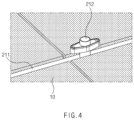
- the pack case 21 is provided with a partition wall 211 that partitions the accommodation space in which the plurality of battery modules 10 are accommodated, and a support member 2121 that supports the pack cover 22 is provided on the partition wall 211. That is, the support member 212 serves to support a central portion of the pack cover 22 so as not to be pressed in a direction of the pack case 21.
- FIG. 4 is a perspective view illustrating the support member provided in the battery pack according to the first embodiment of the present invention.
- the support member 212 has a bolt hole 2121 penetrated vertically, as illustrated in FIG. 4 . That is, the bolt hole 2121 serves as a passage through which the pack case 21 and the pack cover 22 are fixed using bolts and nuts.
- the battery pack according to the related art has a problem in which dew condensation is generated inside the pack case 21 under high temperature and high humidity environments or when there is a large temperature difference between the inside and outside of the pack case.
- the battery pack 1 includes the dew condensation detection sensor 30 that detects the dew condensation generated inside the pack case 21.
- FIG. 5 is a plan view illustrating the dew condensation detection sensor of FIG. 1 according to the first embodiment of the present invention.
- the dew condensation detection sensor 30 is used to detect the dew condensation generated inside the pack housing 20. That is, the dew condensation detection sensor 30 is provided inside the pack case 21 and is connected by the dew condensation (i.e., water droplets W) generated inside the pack case 21 to generate an insulation abnormality signal, thereby detecting an occurrence of the dew condensation through the insulation abnormality signal.
- the dew condensation detection sensor 30 is provided inside the pack case 21 and is connected by the dew condensation (i.e., water droplets W) generated inside the pack case 21 to generate an insulation abnormality signal, thereby detecting an occurrence of the dew condensation through the insulation abnormality signal.
- the dew condensation detection sensor 30 includes a first conductor 31 and a second conductor 32, which are connected by the dew condensation generated inside the pack case 21 to generate the insulation abnormality signal.
- the first conductor 31 includes a first body 311 connected to a voltage line of the battery module 10 and a plurality of first terminals 312 protruding from the first body 311.
- the second conductor 32 includes a second body 321 connected to a ground GND of the pack case 21 and a plurality of second terminals 322 protruding from the second body 321.
- the plurality of first terminals 312 and the plurality of second terminals 322 are alternately disposed and connected by the dew condensation to generate the insulation abnormality signal. That is, referring to FIG. 5 , the water droplets W that is the dew condensation fall to the first terminal 312 and the second terminal 322 so that the first terminal 312 and the second terminal 322 are in contact with each other, and thus, the insulation abnormality signal is generated, and the dew condensation detection sensor 30 detects the occurrence of the dew condensation through the insulation abnormality signal.
- Each of the first conductor 31 and the second conductor 32 may be made of copper or aluminum.
- the dew condensation detection sensor 30 having the above-described configuration may quickly detect the dew condensation generated inside the pack housing 20, and as a result, an occurrence of danger may be detected and prevented at an early stage.
- the first and second conductors 31 and 32 have a structure attached to a surface of an insulating film 33 to prevent the first and second conductors from being in unintentional contact with each other.
- the dew condensation detection sensor 30 may be disposed at a portion of the inside of the pack case 21 at which a lot of dew condensation is generated.
- the dew condensation detection sensor 30 may be attached to the inside of the pack case corresponding to a top surface of the battery module 10, preferably a surface of the pack cover 22 corresponding to the top surface of the battery module 10. That is, due to heat generated from the battery module 10, a lot of dew condensation is generated on the surface of the pack cover 22 corresponding to the top surface of the battery module 10. Thus, the occurrence of the dew condensation may be quickly detected by attaching the dew condensation detection sensor 30 to the surface of the pack cover 22 corresponding to the top surface of the battery module 10.
- the dew condensation detection sensor 30 may be attached to the inside of the pack case that is close to the support member 212 provided in the pack case 21, preferably the surface of the pack cover 22 that is close to the support member 212 provided in the pack case 21. That is, the support member 212 causes a lot of dew condensation on the pack cover 22 on which the support member 212 is disposed due to external air introduced through the bolt hole 2121. Thus, the dew condensation may be quickly detected by attaching the dew condensation detection sensor 30 to the surface of the pack cover 22 that is close to the support member 212.
- a power cutoff device (manual service disconnect (MSD)) that cuts off power connected to the battery module 10 may be provided inside the pack case 21, and the dew condensation detection sensor 30 may be attached to the inside of the pack case that is close to the power cutoff device, preferably a surface of the pack cover 22 that is close to the power cutoff device 23. That is, a lot of dew condensation is generated on the pack cover 22 due to heat generated from the power cutoff device 23. Thus, the dew condensation may be quickly detected by attaching the dew condensation detection sensor 30 to the pack cover 22 that is close to the power cutoff device 23.
- MSD manual service disconnect
- the power cutoff device 23 is a structure for disconnecting the voltage line of the battery module 10 accommodated inside the pack case 21 when inspecting the battery pack 1.
- the dew condensation detection sensor 30 may be attached to the surface of the pack cover 22 using an adhesive 34 or an adhesive film.
- the dew condensation detection sensor 30 may be fitted into and coupled to a hole defined in the pack cover 22 using a bracket. That is, after the dew condensation detection sensor 30 is coupled to the bracket, a coupling part provided on the bracket may be fitted into and coupled to the hole defined in the pack cover 22.
- the battery pack 1 may include the dew condensation detection sensor 30 to quickly detect the dew condensation generated inside the pack case 21, thereby preventing the occurrence of the danger through the cutoff of the power.
- FIG. 6 is a cross-sectional view illustrating a dew condensation removing device of the battery pack according to the first embodiment of the present invention.
- the battery pack 1 may further include a dew condensation removing device 40 that circulates air inside the pack case 21 to remove the dew condensation generated in the pack case 21.
- the dew condensation removing device 40 has a structure that removes the dew condensation generated in the pack case 21 by circulating air outside and inside the pack case 21.
- the dew condensation removing device 40 includes an injection tube 41 and a discharge tube 42, each of which is connected to the inside of the pack case 21, and an air generation part 43 that injects air into the pack case 21 through the injection tube 41 to forcibly discharge air inside the pack case 21 through the discharge tube 42.
- the air generation part 43 operates to supply air to the injection tube 41, and thus, a pressure inside the pack case 21 increases by the air supplied through the injection tube 41 to forcibly discharge the air inside the pack case 21 through the discharge tube 42.
- the dew condensation generated inside the pack case 21 is gradually evaporated to be removed by the air circulating or passing through the inside of the pack case 21.
- the battery pack 1 may include the dew condensation removing device 40 to quickly remove the dew condensation generated inside the pack case 21, and as a result, the occurrence of danger may be prevented to improve safely.
- the dew condensation removing device 40 may further include a valve 44 that opens and closes the injection tube 41 and the discharge tube 42.
- the valve 44 may selectively open and close the injection tube 41 and the discharge tube 42.
- the dew condensation removing device 40 may further include a control part 45 for opening the valve 44 only when the insulation abnormality signal is generated by the dew condensation detection sensor 30 and operating the air generation part 43 so that the air inside the pack case 21 is supplied or discharged.
- a control part 45 for opening the valve 44 only when the insulation abnormality signal is generated by the dew condensation detection sensor 30 and operating the air generation part 43 so that the air inside the pack case 21 is supplied or discharged.
- the dew condensation removing device 40 may further include a filter 46 for filtering the foreign substances contained in the air passing through the injection tube 41.
- the filter may effectively remove the foreign substances contained in the air.
- the battery pack 1 may further include the dew condensation removing device 40 to effectively remove the dew condensation generated inside the pack housing 20.
- a vehicle according to a second embodiment of the present invention has a structure including the battery pack 1 according to the first embodiment.
- the battery pack 1 includes a battery module 10, a pack case 21 in which the battery module 10 is accommodated and which is opened and closed by the pack cover 22, and a dew condensation detection sensor 30 that detects dew condensation through an insulation abnormality signal generated inside the pack case 21, and the dew condensation detection sensor 30 may include a first conductor 31 and a second conductor 32, which are connected by the dew condensation to generate the insulation abnormality signal.
- the battery pack 1 has the same configuration as the battery pack 1 according to the first embodiment, and thus duplicated descriptions will be omitted.
- the vehicle according to the second embodiment of the present invention includes an air conditioning device that circulates air in an interior space in which the driver and assistant ride.
- the air conditioning device may be an air generation part 43 provided in the battery pack 1. That is, when the dew condensation is generated in the battery pack 1, some of the air generated by the air conditioning device is supplied to the inside of the pack case 21 of the battery pack 1. Thus, there is no need to provide a separate air generation part, thereby improving efficiency of use.
- the vehicle according to the second embodiment of the present invention may include the battery pack 1 to improve safety from explosion and ignition.
Landscapes
- Chemical & Material Sciences (AREA)
- Chemical Kinetics & Catalysis (AREA)
- Electrochemistry (AREA)
- General Chemical & Material Sciences (AREA)
- Engineering & Computer Science (AREA)
- Manufacturing & Machinery (AREA)
- Aviation & Aerospace Engineering (AREA)
- Physics & Mathematics (AREA)
- General Physics & Mathematics (AREA)
- Battery Mounting, Suspending (AREA)
- Secondary Cells (AREA)
- Connection Of Batteries Or Terminals (AREA)
Abstract
Description
- The present application claims the benefit of the priority of
Korean Patent Application No. 10-2022-0118218, filed on September 19, 2022 - The present invention relates to a battery pack having a structure capable of detecting dew condensation generated inside a pack case, and a vehicle including the same.
- In general, chargeable and dischargeable secondary batteries may be divided into pouch-type, prismatic, and cylindrical types depending on their structure.
- The pouch-type secondary battery has a structure including an electrode assembly and a pouch accommodating the electrode assembly. The prismatic secondary battery has a structure including an electrode assembly, a can accommodating the electrode assembly, and a top cap coupled to an opening of the can. The cylindrical secondary battery has a structure including an electrode assembly, a can accommodating the electrode assembly, and a cap assembly coupled to an opening of the can.
- Electric vehicles (EV) and hybrid electric vehicles (HEV) are being developed as a method for solving air pollution from existing gasoline and diesel vehicles. The electric vehicles (EV) and hybrid electric vehicles (HEV) use medium-to-large battery modules or medium-to-large battery packs in which multiple secondary batteries are electrically connected as energy sources.
- The battery module has a structure that connects a plurality of secondary batteries in series and/or in parallel, and the battery pack has a structure in which one or more battery modules are embedded into a pack case.
- However, the battery pack has a problem with dew condensation generated inside the pack case under high temperature and humidity environments or when there is a large temperature difference between the inside and outside of the pack case to cause corrosion of the pack case and electrolyte leakage due to cracks in the corroding portion of the pack case, thereby causing a ground fault.
- An object of the present invention is to provide a battery pack, which includes a dew condensation detection sensor that detects dew condensation generated inside a pack case to quickly detect the dew condensation generated inside the pack case, thereby preventing an occurrence of danger at an early stage, and a vehicle including the same.
- Another object of the present invention is to provide a battery pack, which includes a dew condensation removing device that removes dew condensation generated inside a pack case to effectively remove the dew condensation generated inside the pack case, thereby preventing an occurrence of danger at an early stage, and a vehicle including the same.
- A battery pack of the present invention may include: a battery module; a pack housing provided with a pack case, in which the battery module is accommodated, and a pack cover configured to open and close the pack case; and a dew condensation detection sensor configured to detect dew condensation through an insulation abnormality signal generated inside the pack case, wherein the dew condensation detection sensor includes a first conductor and a second conductor connected to each other by the dew condensation generated inside the pack case to generate the insulation abnormality signal.
- The first conductor may include a first body connected to a voltage line of the battery module and a plurality of first terminals protruding from the first body, and the second conductor may include a second body connected to a ground of the pack case and a plurality of second terminals protruding from the second body, wherein the plurality of first terminals and the plurality of second terminals may be alternately disposed and connected to each other by the dew condensation to generate the insulation abnormality signal.
- The dew condensation detection sensor may be attached to a surface of the pack cover corresponding to a top surface of the battery module.
- The battery module may be provided in plurality, the pack case may include: a partition wall configured to partition an accommodation space in which the plurality of battery modules are accommodated; and a support member provided on the partition wall to support the pack cover, and the dew condensation detection sensor may be attached to a surface of the pack cover, which is close to the support member.
- A power cutoff device (manual service disconnect (MSD)) that cuts off power connected to the battery module may be provided inside the pack case, and the dew condensation detection sensor may be attached to a surface of the pack cover, which is close to the power cutoff device.
- The dew condensation detection sensor may be attached to the pack cover using an adhesive or an adhesive film.
- The battery pack may further include a dew condensation removing device configured to circulate air inside the pack case so as to remove the dew condensation generated inside the pack case.
- The dew condensation removing device may include: an injection tube and a discharge tube, which are connected to the inside of the pack case; and an air generation part configured to inject air into the pack case so as to discharge the air inside the pack case through the discharge tube.
- The dew condensation removing device may include: a valve configured to open and close the injection tube and the discharge tube; and a control part configured to open the valve only when the insulation abnormality signal is generated by the dew condensation detection sensor and discharge the air inside the pack case through the air generation part.
- The dew condensation removing device may further include a filter configured to filter foreign substances contained in the air passing through the injection tube.
- Each of the first conductor and the second conductor may be made of copper or aluminum.
- A vehicle of the present invention may include a battery pack including: a battery module; a pack housing provided with a pack case, in which the battery module is accommodated, and a pack cover configured to open and close the pack case; and a dew condensation detection sensor configured to detect dew condensation through an insulation abnormality signal generated inside the pack case, wherein the dew condensation detection sensor includes a first conductor and a second conductor connected to each other by the dew condensation generated inside the pack case to generate the insulation abnormality signal.
- The battery pack of the present invention may include the dew condensation detection sensor that detects the dew condensation through an insulation abnormality signal generated inside the pack case, and the dew condensation detection sensor may include the first conductor and the first conductor, which are connected by the dew condensation to generate the insulation abnormality signal. Due to these features, the dew condensation generated inside the pack case may be quickly detected, and as a result, the occurrence of the danger may be prevented at the early stage.
- That is, in the battery pack of the present invention, the dew condensation detection sensor may be provided at the position corresponding to the top surface of the battery module, the position close to the support member supporting the pack cover, and the position close to the power cutoff device to quickly detect the dew condensation generated inside the pack case.
- In addition, the battery pack of the present invention may be characterized by including the dew condensation removing device that removes the dew condensation generated inside the pack case. Due to this feature, the dew condensation generated inside the pack case may be quickly removed, and as a result, the safety may be improved by preventing the occurrence of danger at the early stage.
-
-
FIG. 1 is a perspective view of a battery back according to a first embodiment of the present invention. -
FIG. 2 is a cross-sectional view ofFIG. 1 . -
FIG. 3 is a schematic plan view illustrating the battery pack ofFIG. 1 . -
FIG. 4 is a perspective view illustrating a support member ofFIG. 1 . -
FIG. 5 is a plan view illustrating a dew condensation detection sensor ofFIG. 1 . -
FIG. 6 is a cross-sectional view illustrating a dew condensation removing device of the battery pack according to the first embodiment of the present invention. -
FIG. 7 is a side view of a vehicle according to a second embodiment of the present invention. - Hereinafter, embodiments of the present invention will be described in detail with reference to the accompanying drawings in such a manner that the technical idea of the present invention may easily be carried out by a person with ordinary skill in the art to which the invention pertains. The present invention may, however, be embodied in different forms and should not be construed as limited to the embodiments set forth herein. In the drawings, anything unnecessary for describing the present invention will be omitted for clarity, and also like reference numerals in the drawings denote like elements.
-
FIG. 1 is a perspective view of a battery back according to a first embodiment of the present invention,FIG. 2 is a cross-sectional view ofFIG. 1 , andFIG. 3 is a schematic plan view illustrating a position of a dew condensation detection sensor provided in the battery pack according to the first embodiment of the present invention. - A
battery pack 1 according to the first embodiment of the present invention has a structure including a dewcondensation detection sensor 30. Due to this structure, dew condensation generated inside the battery pack may be quickly detected, and as a result, danger may be detected or prevented at an early stage. - That is, the
battery pack 1 according to the first embodiment of the present invention, as illustrated inFIGS. 1 to 3 , includes abattery module 10, apack housing 20 in which thebattery module 10 is accommodated, and a dewcondensation detection sensor 30 that detects the dew condensation generated inside thepack housing 20. Here, the dewcondensation detection sensor 30 detects the dew condensation through an insulation abnormality signal generated inside the pack. - The dew condensation refers to a phenomenon in which moisture is formed as water droplets on a surface of an object when a temperature of air containing moisture falls below a dew point. That is, the water droplets is formed inside the battery pack to generate dew condensation due to a temperature difference between the inside and outside of the
battery pack 1 according to the first embodiment of the present invention. - The
battery module 10 has a structure in which a plurality of battery cells are connected in series and/or in parallel. Here, each of the battery cells includes an electrode assembly and a case in which the electrode assembly is accommodated, and the electrode assembly has a structure in which electrodes and separators are alternately arranged. The electrodes may be a positive electrode and a negative electrode. - The
pack housing 20 includes apack case 21 having an accommodation space in which one ormore battery modules 10, preferably two ormore battery modules 10 are accommodated, and apack cover 22 that opens and closes the accommodation space of thepack case 21. - Here, the accommodation space of the
pack case 21 has a structure that is opened upward as illustrated inFIG. 2 , and thepack cover 22 is coupled to an upper portion of thepack case 21 to open and close the accommodation space. - The
pack case 21 is provided with apartition wall 211 that partitions the accommodation space in which the plurality ofbattery modules 10 are accommodated, and a support member 2121 that supports thepack cover 22 is provided on thepartition wall 211. That is, thesupport member 212 serves to support a central portion of thepack cover 22 so as not to be pressed in a direction of thepack case 21. -
FIG. 4 is a perspective view illustrating the support member provided in the battery pack according to the first embodiment of the present invention. - Particularly, the
support member 212 has a bolt hole 2121 penetrated vertically, as illustrated inFIG. 4 . That is, the bolt hole 2121 serves as a passage through which thepack case 21 and thepack cover 22 are fixed using bolts and nuts. - The battery pack according to the related art has a problem in which dew condensation is generated inside the
pack case 21 under high temperature and high humidity environments or when there is a large temperature difference between the inside and outside of the pack case. - The
battery pack 1 according to the first embodiment of the present invention includes the dewcondensation detection sensor 30 that detects the dew condensation generated inside thepack case 21. -
FIG. 5 is a plan view illustrating the dew condensation detection sensor ofFIG. 1 according to the first embodiment of the present invention. - As illustrated in
FIG. 5 , the dewcondensation detection sensor 30 is used to detect the dew condensation generated inside thepack housing 20. That is, the dewcondensation detection sensor 30 is provided inside thepack case 21 and is connected by the dew condensation (i.e., water droplets W) generated inside thepack case 21 to generate an insulation abnormality signal, thereby detecting an occurrence of the dew condensation through the insulation abnormality signal. - For example, the dew
condensation detection sensor 30 includes afirst conductor 31 and asecond conductor 32, which are connected by the dew condensation generated inside thepack case 21 to generate the insulation abnormality signal. - The
first conductor 31 includes afirst body 311 connected to a voltage line of thebattery module 10 and a plurality offirst terminals 312 protruding from thefirst body 311. - The
second conductor 32 includes a second body 321 connected to a ground GND of thepack case 21 and a plurality ofsecond terminals 322 protruding from the second body 321. - Here, the plurality of
first terminals 312 and the plurality ofsecond terminals 322 are alternately disposed and connected by the dew condensation to generate the insulation abnormality signal. That is, referring toFIG. 5 , the water droplets W that is the dew condensation fall to thefirst terminal 312 and thesecond terminal 322 so that thefirst terminal 312 and thesecond terminal 322 are in contact with each other, and thus, the insulation abnormality signal is generated, and the dewcondensation detection sensor 30 detects the occurrence of the dew condensation through the insulation abnormality signal. - Each of the
first conductor 31 and thesecond conductor 32 may be made of copper or aluminum. - The dew
condensation detection sensor 30 having the above-described configuration may quickly detect the dew condensation generated inside thepack housing 20, and as a result, an occurrence of danger may be detected and prevented at an early stage. - The first and
second conductors film 33 to prevent the first and second conductors from being in unintentional contact with each other. - The dew
condensation detection sensor 30 may be disposed at a portion of the inside of thepack case 21 at which a lot of dew condensation is generated. - As a first example, the dew
condensation detection sensor 30 may be attached to the inside of the pack case corresponding to a top surface of thebattery module 10, preferably a surface of thepack cover 22 corresponding to the top surface of thebattery module 10. That is, due to heat generated from thebattery module 10, a lot of dew condensation is generated on the surface of thepack cover 22 corresponding to the top surface of thebattery module 10. Thus, the occurrence of the dew condensation may be quickly detected by attaching the dewcondensation detection sensor 30 to the surface of thepack cover 22 corresponding to the top surface of thebattery module 10. - As a second example, the dew
condensation detection sensor 30 may be attached to the inside of the pack case that is close to thesupport member 212 provided in thepack case 21, preferably the surface of thepack cover 22 that is close to thesupport member 212 provided in thepack case 21. That is, thesupport member 212 causes a lot of dew condensation on thepack cover 22 on which thesupport member 212 is disposed due to external air introduced through the bolt hole 2121. Thus, the dew condensation may be quickly detected by attaching the dewcondensation detection sensor 30 to the surface of thepack cover 22 that is close to thesupport member 212. - As a third example, a power cutoff device (manual service disconnect (MSD)) that cuts off power connected to the
battery module 10 may be provided inside thepack case 21, and the dewcondensation detection sensor 30 may be attached to the inside of the pack case that is close to the power cutoff device, preferably a surface of thepack cover 22 that is close to thepower cutoff device 23. That is, a lot of dew condensation is generated on thepack cover 22 due to heat generated from thepower cutoff device 23. Thus, the dew condensation may be quickly detected by attaching the dewcondensation detection sensor 30 to thepack cover 22 that is close to thepower cutoff device 23. - The
power cutoff device 23 is a structure for disconnecting the voltage line of thebattery module 10 accommodated inside thepack case 21 when inspecting thebattery pack 1. - The dew
condensation detection sensor 30 may be attached to the surface of thepack cover 22 using an adhesive 34 or an adhesive film. - The dew
condensation detection sensor 30 may be fitted into and coupled to a hole defined in thepack cover 22 using a bracket. That is, after the dewcondensation detection sensor 30 is coupled to the bracket, a coupling part provided on the bracket may be fitted into and coupled to the hole defined in thepack cover 22. - Therefore, according to the first embodiment of the present invention, the
battery pack 1 may include the dewcondensation detection sensor 30 to quickly detect the dew condensation generated inside thepack case 21, thereby preventing the occurrence of the danger through the cutoff of the power. -
FIG. 6 is a cross-sectional view illustrating a dew condensation removing device of the battery pack according to the first embodiment of the present invention. - As illustrated in
FIG. 6 , thebattery pack 1 according to the first embodiment of the present invention may further include a dewcondensation removing device 40 that circulates air inside thepack case 21 to remove the dew condensation generated in thepack case 21. - As illustrated in
FIGS. 1 and6 , the dewcondensation removing device 40 has a structure that removes the dew condensation generated in thepack case 21 by circulating air outside and inside thepack case 21. - That is, the dew
condensation removing device 40 includes aninjection tube 41 and adischarge tube 42, each of which is connected to the inside of thepack case 21, and anair generation part 43 that injects air into thepack case 21 through theinjection tube 41 to forcibly discharge air inside thepack case 21 through thedischarge tube 42. - That is, in the dew
condensation removing device 40, when the dewcondensation detection sensor 30 detects the dew condensation generated inside thepack case 21, theair generation part 43 operates to supply air to theinjection tube 41, and thus, a pressure inside thepack case 21 increases by the air supplied through theinjection tube 41 to forcibly discharge the air inside thepack case 21 through thedischarge tube 42. Here, the dew condensation generated inside thepack case 21 is gradually evaporated to be removed by the air circulating or passing through the inside of thepack case 21. - Thus, the
battery pack 1 according to the first embodiment of the present invention may include the dewcondensation removing device 40 to quickly remove the dew condensation generated inside thepack case 21, and as a result, the occurrence of danger may be prevented to improve safely. - The dew
condensation removing device 40 may further include avalve 44 that opens and closes theinjection tube 41 and thedischarge tube 42. Thevalve 44 may selectively open and close theinjection tube 41 and thedischarge tube 42. - In addition, the dew
condensation removing device 40 may further include acontrol part 45 for opening thevalve 44 only when the insulation abnormality signal is generated by the dewcondensation detection sensor 30 and operating theair generation part 43 so that the air inside thepack case 21 is supplied or discharged. Thus, if the dew condensation is not generated inside thepack case 21, theinjection tube 41 and thedischarge tube 42 are closed through thevalve 44 to prevent foreign substances from being introduced into thepack case 21. In addition, when the dew condensation is generated inside thepack case 21, theinjection tube 41 and thedischarge tube 42 are opened through thevalve 44 so that the air inside thepack case 21 is circulated. - The dew
condensation removing device 40 may further include afilter 46 for filtering the foreign substances contained in the air passing through theinjection tube 41. The filter may effectively remove the foreign substances contained in the air. - Thus, the
battery pack 1 according to the first embodiment of the present invention may further include the dewcondensation removing device 40 to effectively remove the dew condensation generated inside thepack housing 20. - Hereinafter, in descriptions of another embodiment of the present invention, constituents having the same function as the above-mentioned embodiment have been given the same reference numeral in the drawings, and thus duplicated description will be omitted.
- As illustrated in
FIG. 7 , a vehicle according to a second embodiment of the present invention has a structure including thebattery pack 1 according to the first embodiment. - Here, the
battery pack 1 includes abattery module 10, apack case 21 in which thebattery module 10 is accommodated and which is opened and closed by thepack cover 22, and a dewcondensation detection sensor 30 that detects dew condensation through an insulation abnormality signal generated inside thepack case 21, and the dewcondensation detection sensor 30 may include afirst conductor 31 and asecond conductor 32, which are connected by the dew condensation to generate the insulation abnormality signal. - Here, the
battery pack 1 has the same configuration as thebattery pack 1 according to the first embodiment, and thus duplicated descriptions will be omitted. - The vehicle according to the second embodiment of the present invention includes an air conditioning device that circulates air in an interior space in which the driver and assistant ride.
- Here, the air conditioning device may be an
air generation part 43 provided in thebattery pack 1. That is, when the dew condensation is generated in thebattery pack 1, some of the air generated by the air conditioning device is supplied to the inside of thepack case 21 of thebattery pack 1. Thus, there is no need to provide a separate air generation part, thereby improving efficiency of use. - Therefore, the vehicle according to the second embodiment of the present invention may include the
battery pack 1 to improve safety from explosion and ignition. - Accordingly, the scope of the present invention is defined by the appended claims more than the foregoing description and the exemplary embodiments described therein. Various modifications made within the meaning of an equivalent of the claims of the invention and within the claims are to be regarded to be in the scope of the present invention.
-
- 1:
- Battery pack
- 10:
- Battery module
- 20:
- Pack housing
- 21:
- Pack case
- 211:
- Partition wall
- 212:
- Support member
- 22:
- Pack cover
- 23:
- Power cutoff device
- 30:
- Dew condensation detection sensor
- 31:
- First conductor
- 311:
- First body
- 312:
- First terminal
- 32:
- Second conductor
- 321:
- Second body
- 322:
- Second terminal
- 33:
- Insulating film
- 34:
- Adhesive
- 40:
- Dew condensation removing device
- 41:
- Injection tube
- 42:
- Discharge tube
- 43:
- Air generation part
- 44:
- Valve
- 45:
- Control part
- 46:
- Filter
Claims (12)
- A battery pack comprising:a battery module;a pack housing provided with a pack case, in which the battery module is accommodated, and a pack cover configured to open and close the pack case; anda dew condensation detection sensor configured to detect dew condensation through an insulation abnormality signal generated inside the pack case,wherein the dew condensation detection sensor comprises a first conductor and a second conductor connected to each other by the dew condensation generated inside the pack case to generate the insulation abnormality signal.
- The battery pack of claim 1, wherein the first conductor comprises a first body connected to a voltage line of the battery module and a plurality of first terminals protruding from the first body, andthe second conductor comprises a second body connected to a ground of the pack case and a plurality of second terminals protruding from the second body,wherein the plurality of first terminals and the plurality of second terminals are alternately disposed and connected to each other by the dew condensation to generate the insulation abnormality signal.
- The battery pack of claim 1, wherein the dew condensation detection sensor is attached to a surface of the pack cover corresponding to a top surface of the battery module.
- The battery pack of claim 1, wherein the battery module is provided in plurality,
the pack case comprises:a partition wall configured to partition an accommodation space in which the plurality of battery modules are accommodated; anda support member provided on the partition wall to support the pack cover, andthe dew condensation detection sensor is attached to a surface of the pack cover, which is close to the support member. - The battery pack of claim 1, wherein a power cutoff device (manual service disconnect (MSD)) that cuts off power connected to the battery module is provided inside the pack case, and
the dew condensation detection sensor is attached to a surface of the pack cover, which is close to the power cutoff device. - The battery pack of claim 1, wherein the dew condensation detection sensor is attached to the pack cover using an adhesive or an adhesive film.
- The battery pack of claim 1, wherein the battery pack further comprises a dew condensation removing device configured to circulate air inside the pack case so as to remove the dew condensation generated inside the pack case.
- The battery pack of claim 7, wherein the dew condensation removing device comprises:an injection tube and a discharge tube, which are connected to the inside of the pack case; andan air generation part configured to inject air into the pack case so as to discharge the air inside the pack case through the discharge tube.
- The battery pack of claim 8, wherein the dew condensation removing device comprises:a valve configured to open and close the injection tube and the discharge tube; anda control part configured to open the valve only when the insulation abnormality signal is generated by the dew condensation detection sensor and discharge the air inside the pack case through the air generation part.
- The battery pack of claim 8, wherein the dew condensation removing device further comprises a filter configured to filter foreign substances contained in the air passing through the injection tube.
- The battery pack of claim 2, wherein each of the first conductor and the second conductor is made of copper or aluminum.
- A vehicle comprising the battery pack of claim 1.
Applications Claiming Priority (2)
| Application Number | Priority Date | Filing Date | Title |
|---|---|---|---|
| KR1020220118218A KR20240039535A (en) | 2022-09-19 | 2022-09-19 | Battery pack and vehicle including the same |
| PCT/KR2023/013845 WO2024063443A1 (en) | 2022-09-19 | 2023-09-14 | Battery pack and vehicle comprising same |
Publications (2)
| Publication Number | Publication Date |
|---|---|
| EP4560781A1 true EP4560781A1 (en) | 2025-05-28 |
| EP4560781A4 EP4560781A4 (en) | 2025-12-17 |
Family
ID=90454854
Family Applications (1)
| Application Number | Title | Priority Date | Filing Date |
|---|---|---|---|
| EP23868497.1A Pending EP4560781A4 (en) | 2022-09-19 | 2023-09-14 | BATTERY PACK AND VEHICLE WITH IT |
Country Status (5)
| Country | Link |
|---|---|
| EP (1) | EP4560781A4 (en) |
| JP (1) | JP2025531883A (en) |
| KR (1) | KR20240039535A (en) |
| CN (1) | CN119816986A (en) |
| WO (1) | WO2024063443A1 (en) |
Families Citing this family (1)
| Publication number | Priority date | Publication date | Assignee | Title |
|---|---|---|---|---|
| CN119108708B (en) * | 2024-11-08 | 2025-03-04 | 深圳永泰数能科技有限公司 | Battery module applied to high-rate charge-discharge liquid cooling heat dissipation and control method |
Family Cites Families (12)
| Publication number | Priority date | Publication date | Assignee | Title |
|---|---|---|---|---|
| JPH05332964A (en) * | 1992-06-02 | 1993-12-17 | Matsushita Electric Works Ltd | Dew sensor |
| JP2007178175A (en) * | 2005-12-27 | 2007-07-12 | Chugoku Electric Power Co Inc:The | Dewing detector and dewing detecting method |
| US7960943B2 (en) * | 2006-11-17 | 2011-06-14 | Cobasys, Llc | Modular battery system having battery monitoring and data collection capability |
| KR100867822B1 (en) | 2006-12-11 | 2008-11-10 | 현대자동차주식회사 | Battery temperature and humidity control unit for hybrid electric vehicles |
| JP2008261691A (en) * | 2007-04-11 | 2008-10-30 | Alps Electric Co Ltd | Condensate sensor |
| JP2010040420A (en) * | 2008-08-07 | 2010-02-18 | Sanyo Electric Co Ltd | Power source device for vehicle |
| JP2012094313A (en) * | 2010-10-26 | 2012-05-17 | Sanyo Electric Co Ltd | Battery unit cooling structure |
| KR20130022145A (en) * | 2011-08-25 | 2013-03-06 | 두산인프라코어 주식회사 | Apparatus and method for detecting water of water cooling type electric power storage module |
| KR101887992B1 (en) * | 2018-02-12 | 2018-09-06 | 주식회사 한국이알이시 | ESS system having arc detector function and temperature detection and condensation detection and ground fault detection |
| JP7059918B2 (en) * | 2018-12-18 | 2022-04-26 | トヨタ自動車株式会社 | Vehicle battery case structure |
| KR102754511B1 (en) * | 2020-10-12 | 2025-01-13 | 주식회사 엘지에너지솔루션 | Battery pack and device including the same |
| KR102536848B1 (en) | 2021-02-18 | 2023-05-26 | 지엠비코리아(주) | Coolant reservoir |
-
2022
- 2022-09-19 KR KR1020220118218A patent/KR20240039535A/en active Pending
-
2023
- 2023-09-14 EP EP23868497.1A patent/EP4560781A4/en active Pending
- 2023-09-14 JP JP2025514828A patent/JP2025531883A/en active Pending
- 2023-09-14 WO PCT/KR2023/013845 patent/WO2024063443A1/en not_active Ceased
- 2023-09-14 CN CN202380062995.1A patent/CN119816986A/en active Pending
Also Published As
| Publication number | Publication date |
|---|---|
| CN119816986A (en) | 2025-04-11 |
| WO2024063443A1 (en) | 2024-03-28 |
| JP2025531883A (en) | 2025-09-25 |
| EP4560781A4 (en) | 2025-12-17 |
| KR20240039535A (en) | 2024-03-26 |
Similar Documents
| Publication | Publication Date | Title |
|---|---|---|
| KR101041153B1 (en) | Secondary Battery and Its Module | |
| KR101330615B1 (en) | Rechargeable battery | |
| US9196920B2 (en) | Electrochemical cell having a safety device | |
| EP3872889B1 (en) | A battery system, a method for leakage detection inside a battery system and a vehicle including a battery system | |
| US9246338B2 (en) | Arrangement and method for safely discharging an energy accumulator | |
| EP1225651A1 (en) | Electric accumulator battery | |
| CN113314771B (en) | Battery system, method for leak detection therein, and vehicle including the same | |
| US10873063B2 (en) | Battery | |
| KR101822612B1 (en) | Battery module for power shut off when battery is over-charged | |
| US9030154B2 (en) | Apparatus and method for preventing battery from being overcharged | |
| US20130344361A1 (en) | Energy Store Unit Having Two Separate Electrochemical Areas | |
| CN220710546U (en) | Battery modules and battery packs | |
| CN119816986A (en) | Battery pack and vehicle including the battery pack | |
| KR20130098336A (en) | Electrochemical cell having at least one pressure relief apparatus | |
| JP4660282B2 (en) | Power supply | |
| JP7151691B2 (en) | power storage device | |
| KR100904375B1 (en) | Fuse-mounted battery cartridges and battery modules containing them | |
| EP3678254A1 (en) | Method for determining the composition of a gaseous mixture enclosed within a gas-tight housing of a battery pack and a corresponding gas-tight housing | |
| KR20140020660A (en) | Test apparatus for battery module | |
| KR20120005726A (en) | Battery cartridge | |
| EP4618253A1 (en) | Battery pack having ignition delay structure | |
| KR102821428B1 (en) | Air Cooling Type Battery Pack and Cooling Method Thereof | |
| CN118281472A (en) | Integrated electrical probe and vent port | |
| EP3367458A1 (en) | Secondary cell for a traction battery and method for manufacturing a secondary cell | |
| KR20250066271A (en) | Battery module capable of detecting electrolyte leakage |
Legal Events
| Date | Code | Title | Description |
|---|---|---|---|
| STAA | Information on the status of an ep patent application or granted ep patent |
Free format text: STATUS: THE INTERNATIONAL PUBLICATION HAS BEEN MADE |
|
| PUAI | Public reference made under article 153(3) epc to a published international application that has entered the european phase |
Free format text: ORIGINAL CODE: 0009012 |
|
| STAA | Information on the status of an ep patent application or granted ep patent |
Free format text: STATUS: REQUEST FOR EXAMINATION WAS MADE |
|
| 17P | Request for examination filed |
Effective date: 20250218 |
|
| AK | Designated contracting states |
Kind code of ref document: A1 Designated state(s): AL AT BE BG CH CY CZ DE DK EE ES FI FR GB GR HR HU IE IS IT LI LT LU LV MC ME MK MT NL NO PL PT RO RS SE SI SK SM TR |
|
| A4 | Supplementary search report drawn up and despatched |
Effective date: 20251114 |
|
| RIC1 | Information provided on ipc code assigned before grant |
Ipc: H01M 10/48 20060101AFI20251110BHEP Ipc: H01M 50/569 20210101ALI20251110BHEP Ipc: H01M 50/271 20210101ALI20251110BHEP Ipc: H01M 50/249 20210101ALI20251110BHEP Ipc: H01M 10/42 20060101ALI20251110BHEP Ipc: H01M 50/574 20210101ALI20251110BHEP Ipc: G01R 31/12 20200101ALI20251110BHEP Ipc: H01M 10/6561 20140101ALI20251110BHEP Ipc: H01M 10/6566 20140101ALI20251110BHEP Ipc: H01M 50/204 20210101ALI20251110BHEP Ipc: H01M 50/24 20210101ALI20251110BHEP |
|
| DAV | Request for validation of the european patent (deleted) | ||
| DAX | Request for extension of the european patent (deleted) |