EP4560775A1 - Battery module including support member including spray hole and battery pack including battery module - Google Patents
Battery module including support member including spray hole and battery pack including battery module Download PDFInfo
- Publication number
- EP4560775A1 EP4560775A1 EP24214112.5A EP24214112A EP4560775A1 EP 4560775 A1 EP4560775 A1 EP 4560775A1 EP 24214112 A EP24214112 A EP 24214112A EP 4560775 A1 EP4560775 A1 EP 4560775A1
- Authority
- EP
- European Patent Office
- Prior art keywords
- extinguishing agent
- fire extinguishing
- battery
- battery module
- cell
- Prior art date
- Legal status (The legal status is an assumption and is not a legal conclusion. Google has not performed a legal analysis and makes no representation as to the accuracy of the status listed.)
- Pending
Links
Images







Classifications
-
- H—ELECTRICITY
- H01—ELECTRIC ELEMENTS
- H01M—PROCESSES OR MEANS, e.g. BATTERIES, FOR THE DIRECT CONVERSION OF CHEMICAL ENERGY INTO ELECTRICAL ENERGY
- H01M50/00—Constructional details or processes of manufacture of the non-active parts of electrochemical cells other than fuel cells, e.g. hybrid cells
- H01M50/20—Mountings; Secondary casings or frames; Racks, modules or packs; Suspension devices; Shock absorbers; Transport or carrying devices; Holders
- H01M50/204—Racks, modules or packs for multiple batteries or multiple cells
- H01M50/207—Racks, modules or packs for multiple batteries or multiple cells characterised by their shape
- H01M50/209—Racks, modules or packs for multiple batteries or multiple cells characterised by their shape adapted for prismatic or rectangular cells
-
- H—ELECTRICITY
- H01—ELECTRIC ELEMENTS
- H01M—PROCESSES OR MEANS, e.g. BATTERIES, FOR THE DIRECT CONVERSION OF CHEMICAL ENERGY INTO ELECTRICAL ENERGY
- H01M10/00—Secondary cells; Manufacture thereof
- H01M10/60—Heating or cooling; Temperature control
- H01M10/65—Means for temperature control structurally associated with the cells
- H01M10/655—Solid structures for heat exchange or heat conduction
- H01M10/6556—Solid parts with flow channel passages or pipes for heat exchange
-
- H—ELECTRICITY
- H01—ELECTRIC ELEMENTS
- H01M—PROCESSES OR MEANS, e.g. BATTERIES, FOR THE DIRECT CONVERSION OF CHEMICAL ENERGY INTO ELECTRICAL ENERGY
- H01M10/00—Secondary cells; Manufacture thereof
- H01M10/42—Methods or arrangements for servicing or maintenance of secondary cells or secondary half-cells
- H01M10/4207—Methods or arrangements for servicing or maintenance of secondary cells or secondary half-cells for several batteries or cells simultaneously or sequentially
-
- A—HUMAN NECESSITIES
- A62—LIFE-SAVING; FIRE-FIGHTING
- A62C—FIRE-FIGHTING
- A62C3/00—Fire prevention, containment or extinguishing specially adapted for particular objects or places
- A62C3/16—Fire prevention, containment or extinguishing specially adapted for particular objects or places in electrical installations, e.g. cableways
-
- A—HUMAN NECESSITIES
- A62—LIFE-SAVING; FIRE-FIGHTING
- A62C—FIRE-FIGHTING
- A62C35/00—Permanently-installed equipment
- A62C35/02—Permanently-installed equipment with containers for delivering the extinguishing substance
- A62C35/11—Permanently-installed equipment with containers for delivering the extinguishing substance controlled by a signal from the danger zone
- A62C35/13—Permanently-installed equipment with containers for delivering the extinguishing substance controlled by a signal from the danger zone with a finite supply of extinguishing material
-
- A—HUMAN NECESSITIES
- A62—LIFE-SAVING; FIRE-FIGHTING
- A62C—FIRE-FIGHTING
- A62C35/00—Permanently-installed equipment
- A62C35/58—Pipe-line systems
- A62C35/68—Details, e.g. of pipes or valve systems
-
- A—HUMAN NECESSITIES
- A62—LIFE-SAVING; FIRE-FIGHTING
- A62C—FIRE-FIGHTING
- A62C37/00—Control of fire-fighting equipment
- A62C37/08—Control of fire-fighting equipment comprising an outlet device containing a sensor, or itself being the sensor, i.e. self-contained sprinklers
-
- F—MECHANICAL ENGINEERING; LIGHTING; HEATING; WEAPONS; BLASTING
- F16—ENGINEERING ELEMENTS AND UNITS; GENERAL MEASURES FOR PRODUCING AND MAINTAINING EFFECTIVE FUNCTIONING OF MACHINES OR INSTALLATIONS; THERMAL INSULATION IN GENERAL
- F16B—DEVICES FOR FASTENING OR SECURING CONSTRUCTIONAL ELEMENTS OR MACHINE PARTS TOGETHER, e.g. NAILS, BOLTS, CIRCLIPS, CLAMPS, CLIPS OR WEDGES; JOINTS OR JOINTING
- F16B5/00—Joining sheets or plates, e.g. panels, to one another or to strips or bars parallel to them
- F16B5/02—Joining sheets or plates, e.g. panels, to one another or to strips or bars parallel to them by means of fastening members using screw-thread
-
- H—ELECTRICITY
- H01—ELECTRIC ELEMENTS
- H01M—PROCESSES OR MEANS, e.g. BATTERIES, FOR THE DIRECT CONVERSION OF CHEMICAL ENERGY INTO ELECTRICAL ENERGY
- H01M10/00—Secondary cells; Manufacture thereof
- H01M10/04—Construction or manufacture in general
- H01M10/0468—Compression means for stacks of electrodes and separators
-
- H—ELECTRICITY
- H01—ELECTRIC ELEMENTS
- H01M—PROCESSES OR MEANS, e.g. BATTERIES, FOR THE DIRECT CONVERSION OF CHEMICAL ENERGY INTO ELECTRICAL ENERGY
- H01M10/00—Secondary cells; Manufacture thereof
- H01M10/42—Methods or arrangements for servicing or maintenance of secondary cells or secondary half-cells
- H01M10/48—Accumulators combined with arrangements for measuring, testing or indicating the condition of cells, e.g. the level or density of the electrolyte
-
- H—ELECTRICITY
- H01—ELECTRIC ELEMENTS
- H01M—PROCESSES OR MEANS, e.g. BATTERIES, FOR THE DIRECT CONVERSION OF CHEMICAL ENERGY INTO ELECTRICAL ENERGY
- H01M10/00—Secondary cells; Manufacture thereof
- H01M10/42—Methods or arrangements for servicing or maintenance of secondary cells or secondary half-cells
- H01M10/48—Accumulators combined with arrangements for measuring, testing or indicating the condition of cells, e.g. the level or density of the electrolyte
- H01M10/482—Accumulators combined with arrangements for measuring, testing or indicating the condition of cells, e.g. the level or density of the electrolyte for several batteries or cells simultaneously or sequentially
-
- H—ELECTRICITY
- H01—ELECTRIC ELEMENTS
- H01M—PROCESSES OR MEANS, e.g. BATTERIES, FOR THE DIRECT CONVERSION OF CHEMICAL ENERGY INTO ELECTRICAL ENERGY
- H01M10/00—Secondary cells; Manufacture thereof
- H01M10/42—Methods or arrangements for servicing or maintenance of secondary cells or secondary half-cells
- H01M10/48—Accumulators combined with arrangements for measuring, testing or indicating the condition of cells, e.g. the level or density of the electrolyte
- H01M10/486—Accumulators combined with arrangements for measuring, testing or indicating the condition of cells, e.g. the level or density of the electrolyte for measuring temperature
-
- H—ELECTRICITY
- H01—ELECTRIC ELEMENTS
- H01M—PROCESSES OR MEANS, e.g. BATTERIES, FOR THE DIRECT CONVERSION OF CHEMICAL ENERGY INTO ELECTRICAL ENERGY
- H01M10/00—Secondary cells; Manufacture thereof
- H01M10/60—Heating or cooling; Temperature control
- H01M10/61—Types of temperature control
- H01M10/613—Cooling or keeping cold
-
- H—ELECTRICITY
- H01—ELECTRIC ELEMENTS
- H01M—PROCESSES OR MEANS, e.g. BATTERIES, FOR THE DIRECT CONVERSION OF CHEMICAL ENERGY INTO ELECTRICAL ENERGY
- H01M10/00—Secondary cells; Manufacture thereof
- H01M10/60—Heating or cooling; Temperature control
- H01M10/63—Control systems
-
- H—ELECTRICITY
- H01—ELECTRIC ELEMENTS
- H01M—PROCESSES OR MEANS, e.g. BATTERIES, FOR THE DIRECT CONVERSION OF CHEMICAL ENERGY INTO ELECTRICAL ENERGY
- H01M10/00—Secondary cells; Manufacture thereof
- H01M10/60—Heating or cooling; Temperature control
- H01M10/64—Heating or cooling; Temperature control characterised by the shape of the cells
- H01M10/647—Prismatic or flat cells, e.g. pouch cells
-
- H—ELECTRICITY
- H01—ELECTRIC ELEMENTS
- H01M—PROCESSES OR MEANS, e.g. BATTERIES, FOR THE DIRECT CONVERSION OF CHEMICAL ENERGY INTO ELECTRICAL ENERGY
- H01M10/00—Secondary cells; Manufacture thereof
- H01M10/60—Heating or cooling; Temperature control
- H01M10/65—Means for temperature control structurally associated with the cells
- H01M10/656—Means for temperature control structurally associated with the cells characterised by the type of heat-exchange fluid
- H01M10/6567—Liquids
-
- H—ELECTRICITY
- H01—ELECTRIC ELEMENTS
- H01M—PROCESSES OR MEANS, e.g. BATTERIES, FOR THE DIRECT CONVERSION OF CHEMICAL ENERGY INTO ELECTRICAL ENERGY
- H01M50/00—Constructional details or processes of manufacture of the non-active parts of electrochemical cells other than fuel cells, e.g. hybrid cells
- H01M50/10—Primary casings; Jackets or wrappings
- H01M50/102—Primary casings; Jackets or wrappings characterised by their shape or physical structure
- H01M50/105—Pouches or flexible bags
-
- H—ELECTRICITY
- H01—ELECTRIC ELEMENTS
- H01M—PROCESSES OR MEANS, e.g. BATTERIES, FOR THE DIRECT CONVERSION OF CHEMICAL ENERGY INTO ELECTRICAL ENERGY
- H01M50/00—Constructional details or processes of manufacture of the non-active parts of electrochemical cells other than fuel cells, e.g. hybrid cells
- H01M50/20—Mountings; Secondary casings or frames; Racks, modules or packs; Suspension devices; Shock absorbers; Transport or carrying devices; Holders
- H01M50/204—Racks, modules or packs for multiple batteries or multiple cells
- H01M50/207—Racks, modules or packs for multiple batteries or multiple cells characterised by their shape
- H01M50/211—Racks, modules or packs for multiple batteries or multiple cells characterised by their shape adapted for pouch cells
-
- H—ELECTRICITY
- H01—ELECTRIC ELEMENTS
- H01M—PROCESSES OR MEANS, e.g. BATTERIES, FOR THE DIRECT CONVERSION OF CHEMICAL ENERGY INTO ELECTRICAL ENERGY
- H01M50/00—Constructional details or processes of manufacture of the non-active parts of electrochemical cells other than fuel cells, e.g. hybrid cells
- H01M50/20—Mountings; Secondary casings or frames; Racks, modules or packs; Suspension devices; Shock absorbers; Transport or carrying devices; Holders
- H01M50/233—Mountings; Secondary casings or frames; Racks, modules or packs; Suspension devices; Shock absorbers; Transport or carrying devices; Holders characterised by physical properties of casings or racks, e.g. dimensions
- H01M50/242—Mountings; Secondary casings or frames; Racks, modules or packs; Suspension devices; Shock absorbers; Transport or carrying devices; Holders characterised by physical properties of casings or racks, e.g. dimensions adapted for protecting batteries against vibrations, collision impact or swelling
-
- H—ELECTRICITY
- H01—ELECTRIC ELEMENTS
- H01M—PROCESSES OR MEANS, e.g. BATTERIES, FOR THE DIRECT CONVERSION OF CHEMICAL ENERGY INTO ELECTRICAL ENERGY
- H01M50/00—Constructional details or processes of manufacture of the non-active parts of electrochemical cells other than fuel cells, e.g. hybrid cells
- H01M50/20—Mountings; Secondary casings or frames; Racks, modules or packs; Suspension devices; Shock absorbers; Transport or carrying devices; Holders
- H01M50/262—Mountings; Secondary casings or frames; Racks, modules or packs; Suspension devices; Shock absorbers; Transport or carrying devices; Holders with fastening means, e.g. locks
- H01M50/264—Mountings; Secondary casings or frames; Racks, modules or packs; Suspension devices; Shock absorbers; Transport or carrying devices; Holders with fastening means, e.g. locks for cells or batteries, e.g. straps, tie rods or peripheral frames
-
- H—ELECTRICITY
- H01—ELECTRIC ELEMENTS
- H01M—PROCESSES OR MEANS, e.g. BATTERIES, FOR THE DIRECT CONVERSION OF CHEMICAL ENERGY INTO ELECTRICAL ENERGY
- H01M50/00—Constructional details or processes of manufacture of the non-active parts of electrochemical cells other than fuel cells, e.g. hybrid cells
- H01M50/30—Arrangements for facilitating escape of gases
- H01M50/383—Flame arresting or ignition-preventing means
-
- H—ELECTRICITY
- H01—ELECTRIC ELEMENTS
- H01M—PROCESSES OR MEANS, e.g. BATTERIES, FOR THE DIRECT CONVERSION OF CHEMICAL ENERGY INTO ELECTRICAL ENERGY
- H01M2200/00—Safety devices for primary or secondary batteries
- H01M2200/10—Temperature sensitive devices
-
- Y—GENERAL TAGGING OF NEW TECHNOLOGICAL DEVELOPMENTS; GENERAL TAGGING OF CROSS-SECTIONAL TECHNOLOGIES SPANNING OVER SEVERAL SECTIONS OF THE IPC; TECHNICAL SUBJECTS COVERED BY FORMER USPC CROSS-REFERENCE ART COLLECTIONS [XRACs] AND DIGESTS
- Y02—TECHNOLOGIES OR APPLICATIONS FOR MITIGATION OR ADAPTATION AGAINST CLIMATE CHANGE
- Y02E—REDUCTION OF GREENHOUSE GAS [GHG] EMISSIONS, RELATED TO ENERGY GENERATION, TRANSMISSION OR DISTRIBUTION
- Y02E60/00—Enabling technologies; Technologies with a potential or indirect contribution to GHG emissions mitigation
- Y02E60/10—Energy storage using batteries
Definitions
- the technology and implementations in this patent document generally relates to a battery module that includes a support member including a spraying hole, and a battery pack that includes the battery module.
- secondary batteries can be recharged and discharged multiple times, making them suitable for a wide range of devices, such as digital cameras, mobile phones, laptops, hybrid vehicles, electric vehicles, and energy storage systems.
- Types of secondary batteries include lithium-ion batteries, nickel-cadmium batteries, nickel-metal hydride batteries, or nickel-hydrogen batteries.
- the disclosed technology can be implemented in some embodiments to provide a battery module that includes a plurality of cell units each including a battery cell and a cell housing supporting the battery cell.
- the battery module can prevent thermal runaway or thermal propagation by inhibiting the spread of heat, gas, or flames generated in one of the plurality of cell units to other cell units.
- the disclosed technology can be implemented in some embodiments to provide a battery module that can deliver a fire extinguishing agent to a battery cell through a support member that supports a plurality of cell units.
- the disclosed technology can be implemented in some embodiments to provide a battery module that can slow fire propagation.
- a battery module and a battery pack based on some embodiments of the disclosed technology may be widely applied in the field of green technology, such as electric vehicles, battery charging stations, and other battery-utilizing solar power generation schemes, wind power generation schemes, or others.
- the battery module and the battery pack implemented based on some embodiments of the disclosed technology may be used in eco-friendly electric vehicles, hybrid vehicles, or others to prevent climate change by reducing air pollution and greenhouse gas emissions.
- a battery module may include a plurality of cell units each including a battery cell and a cell housing that surrounds at least a portion of the battery cell and includes one or more through-holes, one or more support members inserted into the one or more through-holes and configured to support the plurality of cell units, and a fire extinguishing agent supply member connected to the one or more support members and configured to supply a fire extinguishing agent to the one or more support members.
- Each of the one or more support members may include a spraying hole positioned in the one or more through-holes and configured to guide the fire extinguishing agent to the cell unit, and an internal space connected to the spraying hole and configured to provide a path for the fire extinguishing agent.
- the battery module may further include one or more fastening members connecting the one or more support members to the fire extinguishing agent supply member.
- Each of the one or more fastening members may include an external surface including at least a portion that includes a thread in contact with each of the one or more support members.
- Each of the one or more support members includes an internal surface in contact with the fire extinguishing agent supply member, and one or more fluid path holes formed on the internal surface.
- Each of the fastening members may include a head portion surrounding at least a portion of the extinguishing agent supply member, and a protrusion portion extending from the head portion and inserted into the internal space of each of the one or more support members.
- the fire extinguishing agent supply member may include an inlet configured to receive the fire extinguishing agent from outside the battery module, and an outlet configured to supply the fire extinguishing agent to the one or more support members.
- the battery module may further include a fire extinguishing agent tank connected to the fire extinguishing agent supply member and configured to accommodate the fire extinguishing agent.
- the battery module may further include a cover member disposed in the spraying hole.
- a first melting point of the cover member may be lower than a second melting point of the support member.
- the support member and the fire extinguishing agent supply member may be configured to accommodate at least a portion of the fire extinguishing agent in a normal state.
- the term "normal state" refers to a condition where no fire is present in the battery cell.
- the battery module may further include a valve connected to the fire extinguishing agent supply member and configured to control a flow of the fire extinguishing agent from the fire extinguishing agent supply member to the one or more support members.
- the battery module may further include a sensor module configured to detect information on the battery module, including at least one of: flames, sparks, or gas in the battery module or a temperature of the battery module, and a processor configured to control opening and closing of the valve based on the information on the battery module detected by the sensor module,.
- a sensor module configured to detect information on the battery module, including at least one of: flames, sparks, or gas in the battery module or a temperature of the battery module
- a processor configured to control opening and closing of the valve based on the information on the battery module detected by the sensor module,.
- the fire extinguishing agent may flow through the fire extinguishing agent supply member, the internal space, and the spraying hole to reach the battery cell.
- the battery module may further include an end plate disposed at both sides of each of the plurality of cell units, the end plate including a fastening hole configured to accommodate the support member.
- the battery cell may include an electrode assembly, a pouch including an electrode accommodation portion accommodating the electrode assembly and a sealing portion sealing at least a portion of a circumference of the electrode accommodation portion, and an electrode tab connected to the electrode assembly.
- the cell housing may surround at least a portion of the pouch.
- a battery pack may include a plurality of battery modules, and a pack frame configured to accommodate the plurality of battery modules.
- Each of the plurality of battery modules may include a plurality of cell units, each of the plurality of cell units including a battery cell and a cell housing that surrounds at least a portion of the battery cell and includes a through-hole, one or more support members inserted into the one or more through-holes and configured to support the plurality of cell units, and a fire extinguishing agent supply member connected to the one or more support members and configured to supply a fire extinguishing agent to the one or more support members.
- Each of the support members may include a spraying hole positioned in the one or more through-holes and configured to guide the fire extinguishing agent to the cell unit, and an internal space connected to the spraying hole and configured to provide a path for the fire extinguishing agent.
- the battery pack may further include a fire extinguishing agent tank connected to the fire extinguishing agent supply member and configured to accommodate the fire extinguishing agent, and a pump configured to generate pressure to move the fire extinguishing agent from the fire extinguishing agent tank to the fire extinguishing agent supply member.
- the battery module implemented based on an embodiment of the disclosed technology may extinguish a fire before it spreads.
- heat propagation between battery cells may be prevented or delayed.
- the disclosed technology can be implemented in some embodiments to provide a battery module that includes a support member including a spraying hole and a battery pack that includes the battery module.
- Lithium secondary batteries may be manufactured as flexible pouch-type battery cells, rigid prismatic battery cells, or cylindrical can-type battery cells. A plurality of battery cells may be stacked to form a cell assembly.
- a cell assembly may be disposed in a case to form a battery module, and a plurality of battery modules may be disposed in a pack housing to form a battery pack.
- the battery pack may be used in various applications, such as vehicles or energy storage systems.
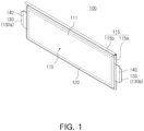
- FIG. 1 is a perspective view of a battery cell based on an embodiment.
- a battery cell 100 may include a pouch 110, an electrode assembly 120, and an electrode tab 130.
- the battery cell 100 may be a secondary battery.
- the battery cell 100 may be a lithium-ion battery, but the disclosed technology is not limited thereto.
- the battery cell 100 may be a nickel-cadmium battery, a nickel-metal hydride battery, or a nickel-hydrogen battery that may be recharged and discharged multiple times.
- the pouch 110 may form at least a portion of an exterior of the battery cell 100.
- the pouch 110 may include an electrode accommodation portion 111 accommodating the electrode assembly 120, and a sealing portion 115 sealing at least a portion of a circumference of the electrode accommodation portion 111.
- the electrode accommodation portion 111 may provide a space in which the electrode assembly 120 and an electrolyte are accommodated.
- the sealing portion 115 may be formed by bonding of at least a portion of a circumference of the pouch 110.
- the sealing portion 115 may be in the form of a flange extending outward from the electrode accommodation portion 111, which serves as a container for electrodes, and may be disposed along at least a portion of an outer perimeter of the electrode accommodation portion 111.
- the sealing portion 115 may include a first sealing portion 115a in which the electrode tab 130 is positioned, and a second sealing portion 115b in which the electrode tab 130 is not positioned. A portion of the electrode tab 130 may be drawn out or exposed to the outside of the pouch 110.
- an insulating film 140 may cover the electrode tab 130 to both enhance the sealing of the first sealing portion 115a and maintain the electrical insulation.
- the insulating film 140 may include a film material that is thinner than the electrode tab 130, and may be attached to both surfaces of the electrode tab 130.
- the electrode tabs 130 may be disposed at both sides of the battery cell 100 in a length direction to be oriented in opposite directions.
- the electrode tab 130 may include a cathode tab 130a having a first polarity (e.g., a cathode) toward one side of the battery cell 100 in the length direction, and an anode tab 130b having a second polarity (e.g., an anode) toward the other side of the battery cell 100 in the length direction.
- the sealing portion 115 may include two first sealing portions 115a on which the electrode tab 130 is disposed and one second sealing portion 115b on which the electrode tab 130 is not disposed. The first sealing portion 115a may seal at least a portion of the electrode tab 130.
- the electrode tab 130 may be referred to as an electrode lead.
- the electrode tab 130 may include a first electrode tab 130a, and a second electrode tab 130b positioned in an opposite direction of the first electrode tab 130a with respect to the electrode assembly 120.
- the electrode tabs 130 is disposed at both sides of the battery cell 100 in the length direction (e.g., Y-axis direction) to be oriented in opposite directions, but the structure of the electrode tabs 130 is not limited thereto.
- two electrode tabs 130 may be arranged to be substantially parallel to each other in the length direction (e.g., Y-axis direction) of the battery cell 100.
- the pouch 110 is not limited to a structure where the sealing portion 115 is formed on three surfaces obtained by folding one sheet of exterior material.
- At least a portion of the sealing portion 115 may be folded at least once. At least a portion of the sealing portion 115 may be folded, thereby improving bonding reliability of the sealing portion 115 and minimizing an area of the sealing portion 115.
- the second sealing portion 115b of the sealing portion 115 based on an embodiment, on which the electrode tab 130 is not disposed, may be folded twice and then fixed by an adhesive member (not illustrated). The angle or the number of bends in the second sealing portion 115b may be adjusted. For example, in an embodiment, the second sealing portion 115b may be folded at 90° angle relative to the first sealing portion 115a.
- the electrode assembly 120 may include a cathode plate, an anode plate, and a separator.
- the separator may prevent contact between the cathode plate and the anode plate.
- the electrode assembly 120 may be manufactured using various methods.
- a cathode, an anode, and a separator may be repeatedly disposed to form an electrode assembly.
- the electrode assembly may be a winding-type electrode assembly, a stacking-type electrode assembly, a Z-folding-type electrode assembly, or a stack-folding-type electrode assembly.
- the structure of the battery cell 100 illustrated in FIG. 1 is only an example.
- the battery cell 100 is described as a pouch-type battery cell, but the structure of the battery cell 100 is not limited thereto.
- the battery cell 100 may be a cylindrical battery cell or a prismatic battery cell.
- FIG. 2 is a plan view of a cell unit based on an embodiment.
- a cell unit 200 may include a cell housing 210 and a battery cell 100 engaged to the cell housing 210. At least a portion of the descriptions of the battery cell 100 of FIG. 1 may be applied to the battery cell 100 of FIG. 2 .
- the cell housing 210 may accommodate and hold the battery cell 100 in place.
- the cell housing 210 may provide an empty space to accommodate the battery cell 100.
- the cell housing 210 may surround at least a portion of the pouch 110 of the battery cell 100.
- the cell housing 210 may protect the battery cell 100 from an external impact of the cell unit 200.
- the cell housing 210 may form at least a portion of an exterior of the cell unit 200. Due to the cell housing 210, a structure (e.g., a module case), required by a battery module (e.g., a battery module 300 of FIG. 3 ), may be omitted.
- the cell housing 210 may be referred to as a cell cartridge.
- the battery module 300 includes one or more housings 210.
- the one or more housings may include a first cell housing 210a and a second cell housing 210b disposed adjacent each other in a stacking direction of the plurality of battery cells 100.
- the cell housing 210 may include a plurality of cell housing portions, spaced apart from each other.
- each of at least one of the one or more cell housings 210 may include a first cell housing portion 211 and a second cell housing portion 212 spaced apart from the first cell housing portion 211.
- the first housing portion 211 surrounds at least a portion of the battery cell 100 and the second housing portion 212 surrounds at least another portion of the battery cell 100.
- the first housing portion 211 disposed upper side portion of the battery cell 100 and the second housing portion 212 disposed lower side portion of the battery cell 100.
- the cell housing 210 may be connected to a support member (e.g., a support member 310 of FIG. 4 ).
- the cell housing 210 may include a through-hole 213 for accommodating the support member 310 by allowing the support member 310 to be inserted and held by the through-hole 213.
- the cell housing 210 may include different through-holes 213 for accommodating different support members 310.
- the through-hole 213 may include at least one first through-hole 213a formed in the first cell housing portion 211, and at least one second through-hole 213b formed in the second cell housing portion 212.
- the cell housing 210 accommodates one or more battery cells 100, but the number of battery cells 100 accommodated in the cell housing 210 may vary.
- the cell housing 210 may accommodate a plurality of battery cells 100 (e.g., two or more battery cells 100).
- FIG. 3 is a perspective view of a battery module based on an embodiment.
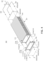
- FIG. 4 is an exploded perspective view of a battery module based on an embodiment.
- FIG. 5 is a perspective view of connection between a support member and a fire extinguishing agent supply member based on an embodiment.
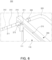
- FIG. 6 is a diagram illustrating a spray path of a fire extinguishing agent for a cell unit based on an embodiment. In FIG. 6 , certain components, such as a portion of an end plate 340 and a cell unit 200 of a battery module 300, are omitted for ease of description.
- the battery module 300 may include a plurality of cell units 200, a support member 310, a fire extinguishing agent supply member 320, a fastening member 330, and an end plate 340. At least a portion of the descriptions of the battery cell 100 and the cell unit 200 of FIGS. 1 and/or 2 may be applied to the battery cell 100 and/or the cell unit 200 of FIGS. 3 , 4 , and/or 6.
- the support member 310 may support the plurality of cell units 200.
- the support member 310 may be inserted into a through-hole 213 of each of the plurality of cell units 200. Positions of the plurality of cell units 200 may be fixed by the support member 310.
- the support member 310 may be referred to as a stay bar.
- the plurality of cell units 200, fixed by the support member 310, may be referred to as sub-battery module 201.
- the support member 310 may be formed of a material for maintaining rigidity of the battery module 300.
- the support member 310 may include stainless steel.
- the support member 310 may be provided as a plurality of support members 310.
- the support member 310 may include a plurality of support members 310a and 310b, supporting the first cell housing portion 211 and the second cell housing portion 212.
- the support member 310 may include at least one first support member 310a inserted into at least one first through-hole 213a formed in the first cell housing portion 211, and at least one second support member 310b inserted into at least one second through-hole 213b formed in the second cell housing portion 212.
- the number of support members 310 may be selectively designed.
- the fire extinguishing agent may pass through the support member 310 which carries and moves a fire extinguishing agent to the cell unit 200.
- the support member 310 may include one or more spraying holes 311 to allow the fire extinguishing agent to exit the support member 310 so that the fire extinguishing agent can reach the cell unit 200 to extinguish fire at the cell unit 200.
- one of the spraying holes 311 may be positioned in the through-hole 213 of the cell housing 210 while other spraying holes 311 may be at other locations on the support member 311.
- the support member 310 may be configured guide a flow of the fire extinguishing agent along the support member 310.
- the support member 310 may include a hollow interior conduit with an internal space 312 for providing a path through which the fire extinguishing agent flows inside the support member 310.
- the support member 310 may be formed to have a tubular shape.
- the support member 310 may include a first end 318 toward the fire extinguishing agent supply member 320 and/or the fastening member 330, and a second end 319 opposite to the first end 318. At least a portion of the fire extinguishing agent, transferred from the first end 318, may be transferred to the second end 319 along the internal space 312 of the support member 310.
- the internal space 312 may be an empty space formed in the support member 310.
- the fire extinguishing agent may pass through the internal space 312 and the spraying hole 311 of the support member 310, and may be transferred to the battery cell 100.
- the support member 310 may be connected to the fire extinguishing agent supply member 320 using the fastening member 330.
- the fire extinguishing agent may be transferred to the support member 310 through the fire extinguishing agent supply member 320 and the fastening member 330.
- the transferred fire extinguishing agent may pass through the spraying hole 311 of the support member 310, and may be transferred to the battery cell 100 of the cell unit 200.
- the fire extinguishing agent sprayed from the spraying hole 311 may be transferred to a gap 215 between the pouch 110 and the cell housing 210. This allows any fire occurring in the battery cell 100 to be suppressed.
- the fire extinguishing agent may be dispersed by pressure passing through the spraying hole 311 and directed toward a center of the battery cell 100.
- the support member 310 may have an internal surface, forming the internal space 312. At least a portion of the internal surface of the support member 310 may be in contact with the fastening member 330. A thread for coupling with the fastening member 330 may be formed on the internal surface. In an embodiment, the fastening member 330 may be a common tapered thread.
- the fire extinguishing agent supply member 320 may provide a path for transferring the fire extinguishing agent to the support member 310.
- the fire extinguishing agent may be transferred to the fire extinguishing agent supply member 320.
- the fire extinguishing agent supply member 320 may include an inlet 321 connected to a fire extinguishing agent tank (e.g., a fire extinguishing agent tank 350 of FIG. 15 ).
- the fire extinguishing agent supply member 320 may transfer the fire extinguishing agent to the support member 310.
- the fire extinguishing agent supply member 320 may include an outlet 322 toward the support member 310.
- the fire extinguishing agent supply member 320 may be referred to as a fire extinguishing agent supply pipe.
- the fastening member 330 may connect the support member 310 and the fire extinguishing agent supply member 320 to each other.
- the fastening member 330 may be connected to the first end 318 of the support member 310 and the outlet 322 of the fire extinguishing agent supply member 320.
- the fastening member 330 may allow the fire extinguishing agent to move therethrough.
- the fastening member 330 may include a fluid path hole (e.g., fluid path hole 331 of FIG. 6 ) providing a path through which the fire extinguishing agent flows.
- the fire extinguishing agent may pass through the fire extinguishing agent supply member 320 and the fastening member 330, and may be transferred to the support member 310.
- the fastening member 330 may be connected to both ends 318 and 319 of the support member 310.
- the fastening member 330 may include a first fastening member 330a connected to the first end 318 of the support member 310, and a second fastening member 330b connected to the second end 319.
- the first fastening member 330a may connect the support member 310 and the fire extinguishing agent supply member 320 to each other.
- the second fastening member 330b may connect the second end 319 of the support member 310 to a pipe (not illustrated).
- the second fastening member 330b may seal the second end 319 without providing the fluid path hole.
- a structure of the fastening member 330 will be further described with reference to FIGS. 6 and 7 .
- the end plate 340 may form at least a portion of an exterior of the battery module 300.
- the end plate 340 may be disposed at both sides of the sub-battery module 201.
- the end plate 340 may include a first end plate 340a positioned at one side of the sub-battery module 201, and a second end plate 340b positioned at the other side of the sub-battery module 201.
- the end plate 340 may include a fastening hole 341 for accommodating the support member 310.
- a portion of the support member 310 may be positioned in the fastening hole 341 of the end plate 340.
- the support member 310 may be inserted into the through-hole 213 of the cell housing 210 of each of the plurality of cell units 200, and the fastening hole 341 of the end plate 340.
- a portion (e.g., an end) of the support member 310 may pass through the through-hole 213 and the fastening hole 341 to be exposed to the outside of the end plate 340.
- the fastening hole 341 of the end plate 340 may accommodate the fastening member 330.
- the number of battery cells 100 may be selectively designed.
- the battery module 300 may include a busbar, electrically connected to the electrode tab 130 of the battery cell 100.
- FIG. 7 is a perspective view of a fastening member based on an embodiment.
- FIG. 8 is a schematic cross-sectional view of a fastening member based on an embodiment.
- a fastening member 330 may connect a support member 310 and a fire extinguishing agent supply member 320 to each other. At least a portion of the descriptions of the fastening member 330 of FIG. 4 , 5 and/or FIG. 6 may be applied to the fastening member 330 of FIG. 7 and FIG. 8 .
- the fastening member 330 may be connected to the support member 310.
- the fastening member 330 may have an external surface 332 in contact with the support member 310.
- the external surface 332 may include a thread 332a.
- a portion of the fastening member 330 may be inserted into an internal space 312 of the support member 310, and the thread 332a of the fastening member 330 may be fastened to a thread (not illustrated) formed on an internal surface of the support member 310.
- the fastening member 330 may provide a fluid path hole of the fire extinguishing agent.
- the fastening member 330 may include a fluid path hole 331 through which the fire extinguishing agent flows.
- the fluid path hole 331 may be an empty space formed by an internal surface 333 of the fastening member 330.
- the fire extinguishing agent transferred from the fire extinguishing agent supply member 320, may move to the support member 310 through the fluid path hole 331.
- the fastening member 330 may be connected to the fire extinguishing agent supply member 320.
- the fastening member 330 may include a connector 334, connected to an outlet (e.g., an outlet 322 of FIG. 4 ) of the fire extinguishing agent supply member 320.
- the connector 334 may be formed to have a structure of a quick connector, and thus may be connected to the fire extinguishing agent supply member 320.
- the shape of the connector 334 illustrated in the drawings are only examples. In an embodiment not illustrated, the outlet 322 of the fire extinguishing agent supply member 320 may be forcibly fitted into the fastening member 330.
- the fastening member 330 may include a sealing member (not illustrated) for preventing leakage of the fire extinguishing agent.
- the sealing member may seal a gap between the support member 310, the fire extinguishing agent supply member 320, and/or the fastening member 330.
- the fastening member 330 may be formed to have a bolt shape.
- the fastening member 330 may include a head portion 335 and a protrusion portion 336 extending from a portion of the head portion 335. At least a portion of the protrusion portion 336 may be inserted into the internal space 312 of the support member 310.
- the thread 332a of the fastening member 330 may be formed on the protrusion portion 336.
- the head portion 335 may be inserted into the internal space 312 of the support member 310.
- the head portion 335 may be fastened to the support member 310 using the thread 332a.
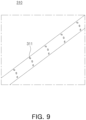
- FIG. 9 is a perspective view of a support member based on an embodiment.
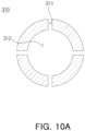
- FIG. 10A is a cross-sectional view of a support member based on an embodiment.
- FIG. 10B is a cross-sectional view of a support member based on another embodiment.
- a support member 310 may include a spraying hole 311 and an internal space 312.
- the descriptions of the support member 310 of FIGS. 4 , 5 , and/or 6 may be applied to the support member 310 of FIGS. 9 , 10A , and 10B .
- the spraying hole 311 of the support member 310 may be connected to the internal space 312.
- a fire extinguishing agent introduced into the internal space 312, may be sprayed onto the outside of the support member 310 through the spraying hole 311.
- a shape of the support member 310 may be selectively designed.
- the shape of the support member 310 is not limited as long as the shape corresponds to a shape of a through-hole (e.g., the through-hole 213 of FIG. 2 ) of a cell housing (e.g., the cell housing 210 of FIG. 2 ).
- the support member 310 may spray the fire extinguishing agent at a plurality of points on substantially the same plane.
- the support member 310 may include a plurality of (e.g., four) spraying holes 311 positioned in a cross-section of the support member 310.
- the support member 310 may have a structure for spraying the fire extinguishing agent in a designated direction.
- the support member 310 may include a single spraying hole 311 positioned in the cross-section of the support member 310.
- the fire extinguishing agent may be sprayed through the spraying hole 311 in the predetermined direction (e.g., toward a gap 215 between a cell housing 210 and a pouch 110), thereby improving spraying efficiency of the fire extinguishing agent.
- the support member 310 may be formed to have a substantially circular cross-section.
- the support member 310 may be formed to have a substantially rectangular cross-section and a circular internal space 312.
- the shape of the support member 310 is not limited thereto.
- the support member 310 may be formed to have a polygonal (e.g., a triangular, a rectangular, a pentagonal, or a hexagonal) cross-section.
- the through-hole 213 of the cell housing 210 of FIG. 2 may be formed to have a shape corresponding to a shape of the cross-section of the support member 310.
- FIG. 11 is a schematic diagram of a battery module in a normal state based on an embodiment.
- FIG. 12 is a schematic diagram of a battery module in a state of combustion based on an embodiment.
- a battery module 300 may include a support member 310, a fire extinguishing agent supply member 320, a fastening member 330, and a fire extinguishing agent tank 350. At least a portion of the descriptions of the battery module 300, the support member 310, the fire extinguishing agent supply member 320, and the fastening member 330 of FIGS. 3 , 4 , 5 , and/or 6 may be applied to the battery module 300, the support member 310, the fire extinguishing agent supply member 320, and the fastening member 330 of FIGS. 11 and 12 .
- certain components of the battery module 300 such as a cell unit 200 and an end plate 340, are omitted from FIGS. 11 and 12 .
- a fire extinguishing agent EA of the battery module 300 may be positioned in the support member 310, the fire extinguishing agent supply member 320, and the fire extinguishing agent tank 350.
- the battery module 300 of FIGS. 11 and 12 may be referred to as a first-type or a wet-type battery module 300.
- the battery module 300 may include a fire extinguishing agent tank 350, accommodating a portion of the fire extinguishing agent EA.
- the fire extinguishing agent tank 350 may accommodate at least a portion of the fire extinguishing agent EA.
- the extinguishing agent EA is not particularly limited as long as it includes materials capable of extinguishing the fire.
- the fire extinguishing agent EA may include at least one of water, insulation cooling water, a foam extinguishing agent, a powder extinguishing agent, or fire extinguishing gas.
- the fire extinguishing agent tank 350 may be connected to the fire extinguishing agent supply member 320.
- the fire extinguishing agent EA accommodated in the fire extinguishing agent tank 350, may pass through the fire extinguishing agent supply member 320, and may be transferred to the support member 310.
- the battery module 300 may include a cover member 313 disposed in a spraying hole 311 of the support member 310.
- the support member 310 may include a plurality of spraying holes 311 and a plurality of cover members 313 disposed in the plurality of spraying holes 311, respectively.
- the support member 310 and the fire extinguishing agent supply member 320 may accommodate at least a portion of the fire extinguishing agent EA.
- the cover member 313 may seal the spraying hole 311 of the support member 310.
- the cover member 313 may prevent leakage of the fire extinguishing agent EA through the spraying hole 311 of the support member 310.
- the cover member 310 may be referred to as a sealing member.
- the cover member 313 may seal the spraying hole 311 in a normal state (e.g., in a state where no fire occurs in the battery module 300, see FIG. 11 ).
- the cover member 313 may be melted before the support member 310 in a state (e.g., FIG. 12 ) in which a fire occurs in the battery module 300 (e.g., the battery cell 100 of FIG. 2 ). As the cover member 313 is melted, the fire extinguishing agent EA positioned in the support member 310 may be sprayed onto the outside of the support member 310 through the spraying hole 311 of the support member 313.
- a first melting point of the cover member 313 may be lower than a second melting point of the support member 310.
- the cover member 313 may include a low melting point material (e.g., a polymer), and the support member 310 may include metal (e.g., aluminum or stainless steel). The first melting point of the cover member 313 may be about 100 degrees to about 300 degrees.
- the plurality of cover members 313 may be melted from the cover member 313 adjacent to the battery cell 100 in which the fire occurs, and may concentrate the fire extinguishing agent EA to a point at which the fire occurs.
- the fire extinguishing agent EA may be sprayed onto the outside of the support member 310 through the spraying hole 311 opened by the melted cover member 313, among the plurality of cover members 313.
- One portion of the fire extinguishing agent EA, sprayed from the support member 310 may be referred to as a spray agent SA.
- the spray agent SA may be concentrated to the point at which the fire occurs, thereby increasing fire extinguishing efficiency.
- FIG. 13 is a schematic diagram of a battery module in a normal state based on an embodiment.
- FIG. 14 is a schematic diagram of a battery module in a state of combustion based on an embodiment.
- a battery module 300 may include a support member 310, a fire extinguishing agent supply member 320, a fastening member 330, a fire extinguishing agent tank 350, a valve 360, a sensor module 370, and a processor 380.
- At least a portion of the descriptions of the battery module 300, the support member 310, the fire extinguishing agent supply member 320, and the fastening member 330 of FIGS. 3 , 4 , 5 , and/or 6 may be applied to the battery module 300, the support member 310, the fire extinguishing agent supply member 320, and the fastening member 330 of FIGS. 11 and 12 .
- certain components of the battery module 300 such as a cell unit 200 and an end plate 340, are omitted from FIGS. 13 and 14 .
- a fire extinguishing agent EA of the battery module 300 may be positioned in the fire extinguishing agent tank 350.
- the battery module 300 of FIGS. 13 and 14 may be referred to as a second-type or a dry-type battery module 300.
- the battery module 300 may include a fire extinguishing agent tank 350, accommodating the fire extinguishing agent EA.
- the fire extinguishing agent tank 350 may accommodate at least a portion of the fire extinguishing agent EA.
- the extinguishing agent EA is not particularly limited as long as it includes materials capable of extinguishing the fire.
- the fire extinguishing agent EA may include at least one of water, insulation cooling water, a foam extinguishing agent, a powder extinguishing agent, or fire extinguishing gas.
- the fire extinguishing agent tank 350 may be connected to the fire extinguishing agent supply member 320.
- the fire extinguishing agent EA accommodated in the fire extinguishing agent tank 350, may pass through the fire extinguishing agent supply member 320, and may be transferred to the support member 310.
- the valve 360 may control a flow of the fire extinguishing agent EA.
- the valve 360 may be positioned between the fire extinguishing agent tank 350 and the fire extinguishing agent supply member 320 or between a plurality of fire extinguishing agent supply members 320.
- the fire extinguishing agent EA accommodated in the fire extinguishing agent tank 350 may be transferred to the support member 310 by opening of the valve 360.
- the sensor module 370 may detect information on the battery module 300. In an embodiment, the sensor module 370 may detect flames, a spark, and/or a specified type of gas in the battery module 300. In an embodiment, the sensor module 370 may detect a temperature of the battery module 300. Information on the battery module 300 may be presence or absence of flames, a spark, or gas in the battery module 300 and/or a temperature of the battery module 300. In an embodiment, the sensor module 370 may be a fire detector.
- the structure in which the sensor module 370 is disposed is only an example.
- the sensor module 370 may be mounted on the battery module 300 or disposed in a battery pack (e.g., a battery pack 400 of FIG. 15 ).
- the processor 380 may control opening and closing of the valve 360, based on the information on the battery module 300 detected by the sensor module 370. For example, the processor 380 may open the valve 360 when the temperature, detected by the sensor module 370, has a value greater than or equal to a specified value. For another example, the processor 380 may open the valve 360 when flames, a spark, and/or a specified type of gas is detected by the sensor module 370.
- the processor 380 may drive a pump (e.g., a pump 351 of FIG. 15 ), based on the information detected by the sensor module 370. For example, the processor 380 may drive the pump 351 when the temperature, detected by the sensor module 370, has a value greater than or equal to a specified value. For another example, the processor 380 may drive the pump 351 when flames, a spark, and/or a specified type of gas is detected by the sensor module 370.
- a pump e.g., a pump 351 of FIG. 15
- the fire extinguishing agent EA positioned in the fire extinguishing agent tank 350, may be transferred to the support member 310.
- the fire extinguishing agent EA, transferred to the support member 310 may be transferred to the outside of the support member 310 (e.g., the cell unit 200 of FIG. 2 ) through the spraying hole 311 of the support member 310.
- One portion of the fire extinguishing agent EA, sprayed from the spraying hole 311 of the support member 310 may be referred to as a spray agent SA.
- the structure in which the processor 380 is disposed may be exemplary.
- the processor 380 may be mounted on the battery module 300.
- the processor 380 may be disposed in a pack frame (e.g., a pack frame 410 of FIG. 15 ).
- the processor 380 may be included in a battery management system (BMS).
- BMS battery management system
- the processor 380 may be positioned on the outside of the battery pack 400.
- the processor 380 may be mounted in a vehicle including the battery pack 400 or an energy storage system including the battery pack 400.
- the battery module 300 illustrated in FIGS. 13 and 14 may be used in combination with the battery module 300 illustrated in FIGS. 11 and 12 .
- the battery module 300 of FIGS. 13 and 14 may include a cover member (e.g., the cover member 313 of FIG. 11 ), positioned in the spraying hole 311 of the support member 310.
- the battery module 300 of FIGS. 11 and 12 may include the valve 360, the sensor module 370, and/or the processor 380 of FIGS. 13 and 14 .
- Fig. 15 is a perspective view of a battery pack based on an embodiment.
- a battery pack 400 may include a pack frame 410, a pack cover 420, a fire extinguishing agent supply member 320, and a fire extinguishing agent tank 350.
- the battery pack 400 may accommodate a plurality of battery modules (e.g., the battery module 300 of FIG. 4 ).
- the battery pack 400 may include a pack frame 410 accommodating the plurality of battery modules 300, and a pack cover 420 covering the pack frame 410 and the plurality of battery modules 300.
- the pack frame 410 and the pack cover 420 may form at least a portion of an exterior of the battery pack 400.
- the fire extinguishing agent supply member 320 may provide a path through which a refrigerant (e.g., a fire extinguishing agent) flows.
- a refrigerant e.g., a fire extinguishing agent
- the fire extinguishing agent supply member 320 may be connected to the fire extinguishing agent tank 350 and/or the pump 351.
- the fire extinguishing agent supply member 320 may be connected to a support member (e.g., the support member 310 of FIG. 4 ) of the battery module 300 positioned in the pack frame 410.
- the fire extinguishing agent supply member 320 may be provided as a plurality of fire extinguishing agent supply members 320.
- the fire extinguishing agent supply member 320 may include at least a portion of a first flow path 325 connected to the pump 351 and the battery module 300, a second flow path 326 connected to the battery module 300 and the fire extinguishing agent tank 350, and a third flow path 327 connected to the pump 351 and the fire extinguishing agent tank 350.
- a position of the fire extinguishing agent tank 350 may be selective.
- the battery module 300 may include a fire extinguishing agent tank 350.
- the fire extinguishing agent tank 350 may be provided as a component separate from the battery module 300.
- the fire extinguishing agent tank 350 may be included in the battery pack 400, a vehicle (not illustrated), or an energy storage system.
- the fire extinguishing agent tank 350 may be connected to at least one battery module 300.
- the pump 351 may generate a pressure difference for a flow of a refrigerant (e.g., the fire extinguishing agent EA of FIG. 11 ).
- a refrigerant e.g., the fire extinguishing agent EA of FIG. 11
- the pump 351 may generate a pressure for movement of the fire extinguishing agent from the fire extinguishing agent tank 350 to the fire extinguishing agent supply member 320.
- the pump 351 may increase pressure such that the refrigerant is circulated in the fire extinguishing agent supply member 320.
- the pump 351 may be connected to the fire extinguishing agent supply member 320 and/or the fire extinguishing agent tank 350. The position of the pump 351 discussed above is only an example.
- the disclosed technology can be implemented in making battery packs with rechargeable secondary batteries that are widely used in battery-powered devices or systems, including, e.g., digital cameras, mobile phones, notebook computers, hybrid vehicles, electric vehicles, uninterruptible power supplies, battery storage power stations, and others including battery power storage for solar panels, wind power generators and other green tech power generators.
- the disclosed technology can be implemented in some embodiments to provide improved electrochemical devices such as a battery pack used in various power sources and power supplies, thereby mitigating climate changes in connection with uses of power sources and power supplies.
- Battery packs based on the disclosed technology can be used to address various adverse effects such as air pollution and greenhouse emissions by powering electric vehicles (EVs) as alternatives to vehicles using fossil fuel-based engines and by providing battery-based energy storage systems (ESSs) to store renewable energy such as solar power and wind power.
- EVs electric vehicles
- ESSs battery-based energy storage systems
Landscapes
- General Chemical & Material Sciences (AREA)
- Chemical & Material Sciences (AREA)
- Electrochemistry (AREA)
- Chemical Kinetics & Catalysis (AREA)
- Engineering & Computer Science (AREA)
- Manufacturing & Machinery (AREA)
- Business, Economics & Management (AREA)
- Emergency Management (AREA)
- Public Health (AREA)
- Health & Medical Sciences (AREA)
- General Engineering & Computer Science (AREA)
- Mechanical Engineering (AREA)
- Automation & Control Theory (AREA)
- Battery Mounting, Suspending (AREA)
Abstract
A battery pack includes a plurality of battery modules, and a pack frame accommodating the plurality of battery modules. Each of the plurality of battery modules includes a plurality of cell units each including a battery cell and a cell housing surrounding at least a portion of the battery cell, the cell housing including one or more through-holes, one or more support members inserted into the one or more through-holes and configured to support the plurality of cell units, and a fire extinguishing agent supply member connected to the one or more support members and configured to supply a fire extinguishing agent to the one or more support members. Each of the one or more support members includes a spraying hole positioned in the one or more through-holes and an internal space connected to the spraying hole and configured to provide a path for the fire extinguishing agent.
Description
- The technology and implementations in this patent document generally relates to a battery module that includes a support member including a spraying hole, and a battery pack that includes the battery module.
- Unlike primary batteries, secondary batteries can be recharged and discharged multiple times, making them suitable for a wide range of devices, such as digital cameras, mobile phones, laptops, hybrid vehicles, electric vehicles, and energy storage systems. Types of secondary batteries include lithium-ion batteries, nickel-cadmium batteries, nickel-metal hydride batteries, or nickel-hydrogen batteries.
- The disclosed technology can be implemented in some embodiments to provide a battery module that includes a plurality of cell units each including a battery cell and a cell housing supporting the battery cell. In an embodiment, the battery module can prevent thermal runaway or thermal propagation by inhibiting the spread of heat, gas, or flames generated in one of the plurality of cell units to other cell units.
- The disclosed technology can be implemented in some embodiments to provide a battery module that can deliver a fire extinguishing agent to a battery cell through a support member that supports a plurality of cell units.
- The disclosed technology can be implemented in some embodiments to provide a battery module that can slow fire propagation.
- A battery module and a battery pack based on some embodiments of the disclosed technology may be widely applied in the field of green technology, such as electric vehicles, battery charging stations, and other battery-utilizing solar power generation schemes, wind power generation schemes, or others. In addition, the battery module and the battery pack implemented based on some embodiments of the disclosed technology may be used in eco-friendly electric vehicles, hybrid vehicles, or others to prevent climate change by reducing air pollution and greenhouse gas emissions.
- In an aspect of the disclosed technology, a battery module may include a plurality of cell units each including a battery cell and a cell housing that surrounds at least a portion of the battery cell and includes one or more through-holes, one or more support members inserted into the one or more through-holes and configured to support the plurality of cell units, and a fire extinguishing agent supply member connected to the one or more support members and configured to supply a fire extinguishing agent to the one or more support members. Each of the one or more support members may include a spraying hole positioned in the one or more through-holes and configured to guide the fire extinguishing agent to the cell unit, and an internal space connected to the spraying hole and configured to provide a path for the fire extinguishing agent.
- The battery module may further include one or more fastening members connecting the one or more support members to the fire extinguishing agent supply member. Each of the one or more fastening members may include an external surface including at least a portion that includes a thread in contact with each of the one or more support members. Each of the one or more support members includes an internal surface in contact with the fire extinguishing agent supply member, and one or more fluid path holes formed on the internal surface.
- Each of the fastening members may include a head portion surrounding at least a portion of the extinguishing agent supply member, and a protrusion portion extending from the head portion and inserted into the internal space of each of the one or more support members.
- The fire extinguishing agent supply member may include an inlet configured to receive the fire extinguishing agent from outside the battery module, and an outlet configured to supply the fire extinguishing agent to the one or more support members.
- The battery module may further include a fire extinguishing agent tank connected to the fire extinguishing agent supply member and configured to accommodate the fire extinguishing agent.
- The battery module may further include a cover member disposed in the spraying hole. A first melting point of the cover member may be lower than a second melting point of the support member.
- The support member and the fire extinguishing agent supply member may be configured to accommodate at least a portion of the fire extinguishing agent in a normal state. In some implementations, the term "normal state" refers to a condition where no fire is present in the battery cell.
- The battery module may further include a valve connected to the fire extinguishing agent supply member and configured to control a flow of the fire extinguishing agent from the fire extinguishing agent supply member to the one or more support members.
- The battery module may further include a sensor module configured to detect information on the battery module, including at least one of: flames, sparks, or gas in the battery module or a temperature of the battery module, and a processor configured to control opening and closing of the valve based on the information on the battery module detected by the sensor module,.
- The fire extinguishing agent may flow through the fire extinguishing agent supply member, the internal space, and the spraying hole to reach the battery cell.
- The battery module may further include an end plate disposed at both sides of each of the plurality of cell units, the end plate including a fastening hole configured to accommodate the support member.
- The cell housing may include a first cell housing portion and a second cell housing portion spaced apart from the first cell housing portion. The one or more through-holes may include at least one first through-hole formed in the first cell housing portion, and at least one second through-hole formed in the second cell housing portion. The one or more support members may include at least one first support member inserted into the at least one first through-hole, and at least one second support member inserted into the at least one second through-hole.
- The battery cell may include an electrode assembly, a pouch including an electrode accommodation portion accommodating the electrode assembly and a sealing portion sealing at least a portion of a circumference of the electrode accommodation portion, and an electrode tab connected to the electrode assembly. The cell housing may surround at least a portion of the pouch.
- In another aspect of the disclosed technology, a battery pack may include a plurality of battery modules, and a pack frame configured to accommodate the plurality of battery modules. Each of the plurality of battery modules may include a plurality of cell units, each of the plurality of cell units including a battery cell and a cell housing that surrounds at least a portion of the battery cell and includes a through-hole, one or more support members inserted into the one or more through-holes and configured to support the plurality of cell units, and a fire extinguishing agent supply member connected to the one or more support members and configured to supply a fire extinguishing agent to the one or more support members. Each of the support members may include a spraying hole positioned in the one or more through-holes and configured to guide the fire extinguishing agent to the cell unit, and an internal space connected to the spraying hole and configured to provide a path for the fire extinguishing agent.
- The battery pack may further include a fire extinguishing agent tank connected to the fire extinguishing agent supply member and configured to accommodate the fire extinguishing agent, and a pump configured to generate pressure to move the fire extinguishing agent from the fire extinguishing agent tank to the fire extinguishing agent supply member.
- The battery module implemented based on an embodiment of the disclosed technology may extinguish a fire before it spreads.
- In an embodiment of the disclosed technology, heat propagation between battery cells may be prevented or delayed.
- Certain aspects, features, and advantages of the disclosed technology are illustrated by the following detailed description with reference to the accompanying drawings.
-
FIG. 1 is a perspective view of a battery cell based on an embodiment. -
FIG. 2 is a plan view of a cell unit based on an embodiment. -
FIG. 3 is a perspective view of a battery module based on an embodiment. -
FIG. 4 is an exploded perspective view of a battery module based on an embodiment. -
FIG. 5 is a perspective view of connection between a support member and a fire extinguishing agent supply member based on an embodiment. -
FIG. 6 is a diagram illustrating a spray path of a fire extinguishing agent for a cell unit based on an embodiment. -
FIG. 7 is a perspective view of a fastening member based on an embodiment. -
FIG. 8 is a schematic cross-sectional view of a fastening member based on an embodiment. -
FIG. 9 is a perspective view of a support member based on an embodiment. -
FIG. 10A is a cross-sectional view of a support member based on an embodiment.FIG. 10B is a cross-sectional view of a support member based on another embodiment. -
FIG. 11 is a schematic diagram of a battery module in a normal state based on an embodiment. -
FIG. 12 is a schematic diagram of a battery module in a state of combustion based on an embodiment. -
FIG. 13 is a schematic diagram of a battery module in a normal state based on an embodiment. -
FIG. 14 is a schematic diagram of a battery module in a state of combustion based on an embodiment. -
FIG. 15 is a perspective view of a battery pack based on an embodiment. - Features of the disclosed technology disclosed in this patent document are described by example embodiments with reference to the accompanying drawings.
- The disclosed technology can be implemented in some embodiments to provide a battery module that includes a support member including a spraying hole and a battery pack that includes the battery module.
- The following disclosure provides a detained description with reference to the accompanying drawings. However, the embodiments are merely examples, and the disclosed technology is not limited to specific embodiments.
- Lithium secondary batteries may be manufactured as flexible pouch-type battery cells, rigid prismatic battery cells, or cylindrical can-type battery cells. A plurality of battery cells may be stacked to form a cell assembly.
- A cell assembly may be disposed in a case to form a battery module, and a plurality of battery modules may be disposed in a pack housing to form a battery pack. The battery pack may be used in various applications, such as vehicles or energy storage systems.
-
FIG. 1 is a perspective view of a battery cell based on an embodiment. - Referring to
FIG. 1 , abattery cell 100 may include apouch 110, anelectrode assembly 120, and anelectrode tab 130. Thebattery cell 100 may be a secondary battery. For example, thebattery cell 100 may be a lithium-ion battery, but the disclosed technology is not limited thereto. For example, thebattery cell 100 may be a nickel-cadmium battery, a nickel-metal hydride battery, or a nickel-hydrogen battery that may be recharged and discharged multiple times. - The
pouch 110 may form at least a portion of an exterior of thebattery cell 100. Thepouch 110 may include anelectrode accommodation portion 111 accommodating theelectrode assembly 120, and a sealingportion 115 sealing at least a portion of a circumference of theelectrode accommodation portion 111. Theelectrode accommodation portion 111 may provide a space in which theelectrode assembly 120 and an electrolyte are accommodated. - The sealing
portion 115 may be formed by bonding of at least a portion of a circumference of thepouch 110. The sealingportion 115 may be in the form of a flange extending outward from theelectrode accommodation portion 111, which serves as a container for electrodes, and may be disposed along at least a portion of an outer perimeter of theelectrode accommodation portion 111. In an embodiment, the sealingportion 115 may include afirst sealing portion 115a in which theelectrode tab 130 is positioned, and asecond sealing portion 115b in which theelectrode tab 130 is not positioned. A portion of theelectrode tab 130 may be drawn out or exposed to the outside of thepouch 110. In a position in which theelectrode tab 130 is drawn out, an insulatingfilm 140 may cover theelectrode tab 130 to both enhance the sealing of thefirst sealing portion 115a and maintain the electrical insulation. The insulatingfilm 140 may include a film material that is thinner than theelectrode tab 130, and may be attached to both surfaces of theelectrode tab 130. - In an embodiment, the
electrode tabs 130 may be disposed at both sides of thebattery cell 100 in a length direction to be oriented in opposite directions. For example, theelectrode tab 130 may include acathode tab 130a having a first polarity (e.g., a cathode) toward one side of thebattery cell 100 in the length direction, and ananode tab 130b having a second polarity (e.g., an anode) toward the other side of thebattery cell 100 in the length direction. In the example configuration illustrated inFIG. 1 , the sealingportion 115 may include twofirst sealing portions 115a on which theelectrode tab 130 is disposed and onesecond sealing portion 115b on which theelectrode tab 130 is not disposed. Thefirst sealing portion 115a may seal at least a portion of theelectrode tab 130. In an embodiment, theelectrode tab 130 may be referred to as an electrode lead. - The orientation of the
electrode tab 130 may be selectively designed. In an embodiment (e.g.,FIG. 1 ), theelectrode tab 130 may include afirst electrode tab 130a, and asecond electrode tab 130b positioned in an opposite direction of thefirst electrode tab 130a with respect to theelectrode assembly 120. As shown inFIG. 1 , in some implementations, theelectrode tabs 130 is disposed at both sides of thebattery cell 100 in the length direction (e.g., Y-axis direction) to be oriented in opposite directions, but the structure of theelectrode tabs 130 is not limited thereto. For example, twoelectrode tabs 130 may be arranged to be substantially parallel to each other in the length direction (e.g., Y-axis direction) of thebattery cell 100. - As illustrated in
FIG. 1 , thepouch 110 is not limited to a structure where the sealingportion 115 is formed on three surfaces obtained by folding one sheet of exterior material. - In an embodiment of the disclosed technology, at least a portion of the sealing
portion 115 may be folded at least once. At least a portion of the sealingportion 115 may be folded, thereby improving bonding reliability of the sealingportion 115 and minimizing an area of the sealingportion 115. Thesecond sealing portion 115b of the sealingportion 115 based on an embodiment, on which theelectrode tab 130 is not disposed, may be folded twice and then fixed by an adhesive member (not illustrated). The angle or the number of bends in thesecond sealing portion 115b may be adjusted. For example, in an embodiment, thesecond sealing portion 115b may be folded at 90° angle relative to thefirst sealing portion 115a. - The
electrode assembly 120 may include a cathode plate, an anode plate, and a separator. The separator may prevent contact between the cathode plate and the anode plate. In some implementations, theelectrode assembly 120 may be manufactured using various methods. In embodiments, a cathode, an anode, and a separator may be repeatedly disposed to form an electrode assembly. In some embodiments, the electrode assembly may be a winding-type electrode assembly, a stacking-type electrode assembly, a Z-folding-type electrode assembly, or a stack-folding-type electrode assembly. - The structure of the
battery cell 100 illustrated inFIG. 1 is only an example. For example, inFIG. 1 , thebattery cell 100 is described as a pouch-type battery cell, but the structure of thebattery cell 100 is not limited thereto. For example, thebattery cell 100 may be a cylindrical battery cell or a prismatic battery cell. -
FIG. 2 is a plan view of a cell unit based on an embodiment. - Referring to
FIG. 2 , acell unit 200 may include acell housing 210 and abattery cell 100 engaged to thecell housing 210. At least a portion of the descriptions of thebattery cell 100 ofFIG. 1 may be applied to thebattery cell 100 ofFIG. 2 . - The
cell housing 210 may accommodate and hold thebattery cell 100 in place. Thecell housing 210 may provide an empty space to accommodate thebattery cell 100. Thecell housing 210 may surround at least a portion of thepouch 110 of thebattery cell 100. Thecell housing 210 may protect thebattery cell 100 from an external impact of thecell unit 200. Thecell housing 210 may form at least a portion of an exterior of thecell unit 200. Due to thecell housing 210, a structure (e.g., a module case), required by a battery module (e.g., abattery module 300 ofFIG. 3 ), may be omitted. In an embodiment, thecell housing 210 may be referred to as a cell cartridge. - In an embodiment, the
battery module 300 includes one ormore housings 210. The one or more housings may include afirst cell housing 210a and asecond cell housing 210b disposed adjacent each other in a stacking direction of the plurality ofbattery cells 100. In an embodiment, thecell housing 210 may include a plurality of cell housing portions, spaced apart from each other. For example, each of at least one of the one ormore cell housings 210 may include a firstcell housing portion 211 and a secondcell housing portion 212 spaced apart from the firstcell housing portion 211. In an embodiment, thefirst housing portion 211 surrounds at least a portion of thebattery cell 100 and thesecond housing portion 212 surrounds at least another portion of thebattery cell 100. For example, thefirst housing portion 211 disposed upper side portion of thebattery cell 100 and thesecond housing portion 212 disposed lower side portion of thebattery cell 100. - The
cell housing 210 may be connected to a support member (e.g., asupport member 310 ofFIG. 4 ). For example, thecell housing 210 may include a through-hole 213 for accommodating thesupport member 310 by allowing thesupport member 310 to be inserted and held by the through-hole 213. In an embodiment, thecell housing 210 may include different through-holes 213 for accommodatingdifferent support members 310. For example, the through-hole 213 may include at least one first through-hole 213a formed in the firstcell housing portion 211, and at least one second through-hole 213b formed in the secondcell housing portion 212. - In an embodiment of the disclosed technology, the
cell housing 210 accommodates one ormore battery cells 100, but the number ofbattery cells 100 accommodated in thecell housing 210 may vary. For example, in an embodiment, thecell housing 210 may accommodate a plurality of battery cells 100 (e.g., two or more battery cells 100). -
FIG. 3 is a perspective view of a battery module based on an embodiment.FIG. 4 is an exploded perspective view of a battery module based on an embodiment.FIG. 5 is a perspective view of connection between a support member and a fire extinguishing agent supply member based on an embodiment.FIG. 6 is a diagram illustrating a spray path of a fire extinguishing agent for a cell unit based on an embodiment. InFIG. 6 , certain components, such as a portion of anend plate 340 and acell unit 200 of abattery module 300, are omitted for ease of description. - Referring to
FIGS. 3 ,4 ,5 , and/or 6, thebattery module 300 may include a plurality ofcell units 200, asupport member 310, a fire extinguishingagent supply member 320, afastening member 330, and anend plate 340. At least a portion of the descriptions of thebattery cell 100 and thecell unit 200 ofFIGS. 1 and/or 2 may be applied to thebattery cell 100 and/or thecell unit 200 ofFIGS. 3 ,4 , and/or 6. - The
support member 310 may support the plurality ofcell units 200. For example, thesupport member 310 may be inserted into a through-hole 213 of each of the plurality ofcell units 200. Positions of the plurality ofcell units 200 may be fixed by thesupport member 310. In an embodiment, thesupport member 310 may be referred to as a stay bar. The plurality ofcell units 200, fixed by thesupport member 310, may be referred to assub-battery module 201. - The
support member 310 may be formed of a material for maintaining rigidity of thebattery module 300. For example, thesupport member 310 may include stainless steel. - The
support member 310 may be provided as a plurality ofsupport members 310. In an embodiment, thesupport member 310 may include a plurality ofsupport members cell housing portion 211 and the secondcell housing portion 212. For example, thesupport member 310 may include at least onefirst support member 310a inserted into at least one first through-hole 213a formed in the firstcell housing portion 211, and at least onesecond support member 310b inserted into at least one second through-hole 213b formed in the secondcell housing portion 212. The number ofsupport members 310 may be selectively designed. - The fire extinguishing agent may pass through the
support member 310 which carries and moves a fire extinguishing agent to thecell unit 200. For example, thesupport member 310 may include one or more spraying holes 311 to allow the fire extinguishing agent to exit thesupport member 310 so that the fire extinguishing agent can reach thecell unit 200 to extinguish fire at thecell unit 200. As illustrated inFIG. 6 , one of the spraying holes 311 may be positioned in the through-hole 213 of thecell housing 210 while other sprayingholes 311 may be at other locations on thesupport member 311. - The
support member 310 may be configured guide a flow of the fire extinguishing agent along thesupport member 310. For example, thesupport member 310 may include a hollow interior conduit with aninternal space 312 for providing a path through which the fire extinguishing agent flows inside thesupport member 310. Thesupport member 310 may be formed to have a tubular shape. For example, thesupport member 310 may include afirst end 318 toward the fire extinguishingagent supply member 320 and/or thefastening member 330, and asecond end 319 opposite to thefirst end 318. At least a portion of the fire extinguishing agent, transferred from thefirst end 318, may be transferred to thesecond end 319 along theinternal space 312 of thesupport member 310. Theinternal space 312 may be an empty space formed in thesupport member 310. The fire extinguishing agent may pass through theinternal space 312 and thespraying hole 311 of thesupport member 310, and may be transferred to thebattery cell 100. Thesupport member 310 may be connected to the fire extinguishingagent supply member 320 using thefastening member 330. For example, the fire extinguishing agent may be transferred to thesupport member 310 through the fire extinguishingagent supply member 320 and thefastening member 330. The transferred fire extinguishing agent may pass through thespraying hole 311 of thesupport member 310, and may be transferred to thebattery cell 100 of thecell unit 200. For example, at least a portion of the fire extinguishing agent, sprayed from the sprayinghole 311, may be transferred to agap 215 between thepouch 110 and thecell housing 210. This allows any fire occurring in thebattery cell 100 to be suppressed. For example, the fire extinguishing agent may be dispersed by pressure passing through thespraying hole 311 and directed toward a center of thebattery cell 100. - The
support member 310 may have an internal surface, forming theinternal space 312. At least a portion of the internal surface of thesupport member 310 may be in contact with thefastening member 330. A thread for coupling with thefastening member 330 may be formed on the internal surface. In an embodiment, thefastening member 330 may be a common tapered thread. - The fire extinguishing
agent supply member 320 may provide a path for transferring the fire extinguishing agent to thesupport member 310. The fire extinguishing agent may be transferred to the fire extinguishingagent supply member 320. For example, the fire extinguishingagent supply member 320 may include aninlet 321 connected to a fire extinguishing agent tank (e.g., a fire extinguishingagent tank 350 ofFIG. 15 ). The fire extinguishingagent supply member 320 may transfer the fire extinguishing agent to thesupport member 310. For example, the fire extinguishingagent supply member 320 may include anoutlet 322 toward thesupport member 310. In an embodiment, the fire extinguishingagent supply member 320 may be referred to as a fire extinguishing agent supply pipe. - The
fastening member 330 may connect thesupport member 310 and the fire extinguishingagent supply member 320 to each other. For example, thefastening member 330 may be connected to thefirst end 318 of thesupport member 310 and theoutlet 322 of the fire extinguishingagent supply member 320. - The
fastening member 330 may allow the fire extinguishing agent to move therethrough. For example, thefastening member 330 may include a fluid path hole (e.g., fluid path hole 331 ofFIG. 6 ) providing a path through which the fire extinguishing agent flows. The fire extinguishing agent may pass through the fire extinguishingagent supply member 320 and thefastening member 330, and may be transferred to thesupport member 310. - The
fastening member 330 may be connected to both ends 318 and 319 of thesupport member 310. For example, thefastening member 330 may include afirst fastening member 330a connected to thefirst end 318 of thesupport member 310, and asecond fastening member 330b connected to thesecond end 319. Thefirst fastening member 330a may connect thesupport member 310 and the fire extinguishingagent supply member 320 to each other. In an embodiment, thesecond fastening member 330b may connect thesecond end 319 of thesupport member 310 to a pipe (not illustrated). In another embodiment, thesecond fastening member 330b may seal thesecond end 319 without providing the fluid path hole. A structure of thefastening member 330 will be further described with reference toFIGS. 6 and7 . - The
end plate 340 may form at least a portion of an exterior of thebattery module 300. For example, theend plate 340 may be disposed at both sides of thesub-battery module 201. Theend plate 340 may include afirst end plate 340a positioned at one side of thesub-battery module 201, and asecond end plate 340b positioned at the other side of thesub-battery module 201. - In an embodiment, the
end plate 340 may include afastening hole 341 for accommodating thesupport member 310. A portion of thesupport member 310 may be positioned in thefastening hole 341 of theend plate 340. Thesupport member 310 may be inserted into the through-hole 213 of thecell housing 210 of each of the plurality ofcell units 200, and thefastening hole 341 of theend plate 340. A portion (e.g., an end) of thesupport member 310 may pass through the through-hole 213 and thefastening hole 341 to be exposed to the outside of theend plate 340. In another embodiment, thefastening hole 341 of theend plate 340 may accommodate thefastening member 330. - For ease of description, certain components are omitted or exaggerated in some embodiments of the disclosed technology. For example, the number of
battery cells 100 may be selectively designed. - In an embodiment not illustrated, the
battery module 300 may include a busbar, electrically connected to theelectrode tab 130 of thebattery cell 100. -
FIG. 7 is a perspective view of a fastening member based on an embodiment.FIG. 8 is a schematic cross-sectional view of a fastening member based on an embodiment. - Referring to
FIG. 7 and/orFIG. 8 together withFIG. 5 andFIG. 6 , afastening member 330 may connect asupport member 310 and a fire extinguishingagent supply member 320 to each other. At least a portion of the descriptions of thefastening member 330 ofFIG. 4 ,5 and/orFIG. 6 may be applied to thefastening member 330 ofFIG. 7 andFIG. 8 . - The
fastening member 330 may be connected to thesupport member 310. For example, thefastening member 330 may have anexternal surface 332 in contact with thesupport member 310. Theexternal surface 332 may include athread 332a. A portion of thefastening member 330 may be inserted into aninternal space 312 of thesupport member 310, and thethread 332a of thefastening member 330 may be fastened to a thread (not illustrated) formed on an internal surface of thesupport member 310. - The
fastening member 330 may provide a fluid path hole of the fire extinguishing agent. Thefastening member 330 may include a fluid path hole 331 through which the fire extinguishing agent flows. The fluid path hole 331 may be an empty space formed by aninternal surface 333 of thefastening member 330. The fire extinguishing agent, transferred from the fire extinguishingagent supply member 320, may move to thesupport member 310 through thefluid path hole 331. - The
fastening member 330 may be connected to the fire extinguishingagent supply member 320. For example, thefastening member 330 may include aconnector 334, connected to an outlet (e.g., anoutlet 322 ofFIG. 4 ) of the fire extinguishingagent supply member 320. Theconnector 334 may be formed to have a structure of a quick connector, and thus may be connected to the fire extinguishingagent supply member 320. The shape of theconnector 334 illustrated in the drawings are only examples. In an embodiment not illustrated, theoutlet 322 of the fire extinguishingagent supply member 320 may be forcibly fitted into thefastening member 330. - In an embodiment, the
fastening member 330 may include a sealing member (not illustrated) for preventing leakage of the fire extinguishing agent. The sealing member may seal a gap between thesupport member 310, the fire extinguishingagent supply member 320, and/or thefastening member 330. - The
fastening member 330 may be formed to have a bolt shape. For example, thefastening member 330 may include ahead portion 335 and aprotrusion portion 336 extending from a portion of thehead portion 335. At least a portion of theprotrusion portion 336 may be inserted into theinternal space 312 of thesupport member 310. Thethread 332a of thefastening member 330 may be formed on theprotrusion portion 336. Thehead portion 335 may be inserted into theinternal space 312 of thesupport member 310. Thehead portion 335 may be fastened to thesupport member 310 using thethread 332a. -
FIG. 9 is a perspective view of a support member based on an embodiment.FIG. 10A is a cross-sectional view of a support member based on an embodiment.FIG. 10B is a cross-sectional view of a support member based on another embodiment. - Referring to
FIGS. 9 ,10A , and/or 10B, asupport member 310 may include aspraying hole 311 and aninternal space 312. The descriptions of thesupport member 310 ofFIGS. 4 ,5 , and/or 6 may be applied to thesupport member 310 ofFIGS. 9 ,10A , and10B . - The spraying
hole 311 of thesupport member 310 may be connected to theinternal space 312. For example, a fire extinguishing agent, introduced into theinternal space 312, may be sprayed onto the outside of thesupport member 310 through thespraying hole 311. - A shape of the
support member 310 may be selectively designed. The shape of thesupport member 310 is not limited as long as the shape corresponds to a shape of a through-hole (e.g., the through-hole 213 ofFIG. 2 ) of a cell housing (e.g., thecell housing 210 ofFIG. 2 ). - In an embodiment (e.g.,
FIG. 10A ), thesupport member 310 may spray the fire extinguishing agent at a plurality of points on substantially the same plane. Thesupport member 310 may include a plurality of (e.g., four) sprayingholes 311 positioned in a cross-section of thesupport member 310. - In an embodiment (e.g.,
FIG. 10B ), thesupport member 310 may have a structure for spraying the fire extinguishing agent in a designated direction. For example, thesupport member 310 may include asingle spraying hole 311 positioned in the cross-section of thesupport member 310. The fire extinguishing agent may be sprayed through thespraying hole 311 in the predetermined direction (e.g., toward agap 215 between acell housing 210 and a pouch 110), thereby improving spraying efficiency of the fire extinguishing agent. - In an embodiment (e.g.,
FIGS. 9 and10A ), thesupport member 310 may be formed to have a substantially circular cross-section. In an embodiment (e.g.,FIG. 10B ), thesupport member 310 may be formed to have a substantially rectangular cross-section and a circularinternal space 312. - However, the shape of the
support member 310 is not limited thereto. For example, thesupport member 310 may be formed to have a polygonal (e.g., a triangular, a rectangular, a pentagonal, or a hexagonal) cross-section. The through-hole 213 of thecell housing 210 ofFIG. 2 may be formed to have a shape corresponding to a shape of the cross-section of thesupport member 310. -
FIG. 11 is a schematic diagram of a battery module in a normal state based on an embodiment.FIG. 12 is a schematic diagram of a battery module in a state of combustion based on an embodiment. - Referring to
FIGS. 11 and12 , abattery module 300 may include asupport member 310, a fire extinguishingagent supply member 320, afastening member 330, and a fire extinguishingagent tank 350. At least a portion of the descriptions of thebattery module 300, thesupport member 310, the fire extinguishingagent supply member 320, and thefastening member 330 ofFIGS. 3 ,4 ,5 , and/or 6 may be applied to thebattery module 300, thesupport member 310, the fire extinguishingagent supply member 320, and thefastening member 330 ofFIGS. 11 and12 . For ease of description, certain components of thebattery module 300, such as acell unit 200 and anend plate 340, are omitted fromFIGS. 11 and12 . - In an embodiment (e.g.,
FIGS. 11 and12 ), a fire extinguishing agent EA of thebattery module 300 may be positioned in thesupport member 310, the fire extinguishingagent supply member 320, and the fire extinguishingagent tank 350. Thebattery module 300 ofFIGS. 11 and12 may be referred to as a first-type or a wet-type battery module 300. - The
battery module 300 may include a fire extinguishingagent tank 350, accommodating a portion of the fire extinguishing agent EA. The fire extinguishingagent tank 350 may accommodate at least a portion of the fire extinguishing agent EA. The extinguishing agent EA is not particularly limited as long as it includes materials capable of extinguishing the fire. For example, the fire extinguishing agent EA may include at least one of water, insulation cooling water, a foam extinguishing agent, a powder extinguishing agent, or fire extinguishing gas. - The fire extinguishing
agent tank 350 may be connected to the fire extinguishingagent supply member 320. For example, the fire extinguishing agent EA, accommodated in the fire extinguishingagent tank 350, may pass through the fire extinguishingagent supply member 320, and may be transferred to thesupport member 310. - In an embodiment (e.g.,
FIGS. 11 and12 ), thebattery module 300 may include acover member 313 disposed in aspraying hole 311 of thesupport member 310. For example, thesupport member 310 may include a plurality of sprayingholes 311 and a plurality ofcover members 313 disposed in the plurality of sprayingholes 311, respectively. In a state in which no fire occurs in the battery module 300 (e.g., a normal state ofFIG. 11 ), thesupport member 310 and the fire extinguishingagent supply member 320 may accommodate at least a portion of the fire extinguishing agent EA. Thecover member 313 may seal thespraying hole 311 of thesupport member 310. Thecover member 313 may prevent leakage of the fire extinguishing agent EA through thespraying hole 311 of thesupport member 310. In an embodiment, thecover member 310 may be referred to as a sealing member. - The
cover member 313 may seal thespraying hole 311 in a normal state (e.g., in a state where no fire occurs in thebattery module 300, seeFIG. 11 ). - The
cover member 313 may be melted before thesupport member 310 in a state (e.g.,FIG. 12 ) in which a fire occurs in the battery module 300 (e.g., thebattery cell 100 ofFIG. 2 ). As thecover member 313 is melted, the fire extinguishing agent EA positioned in thesupport member 310 may be sprayed onto the outside of thesupport member 310 through thespraying hole 311 of thesupport member 313. A first melting point of thecover member 313 may be lower than a second melting point of thesupport member 310. In an embodiment, thecover member 313 may include a low melting point material (e.g., a polymer), and thesupport member 310 may include metal (e.g., aluminum or stainless steel). The first melting point of thecover member 313 may be about 100 degrees to about 300 degrees. - In an embodiment, the plurality of
cover members 313 may be melted from thecover member 313 adjacent to thebattery cell 100 in which the fire occurs, and may concentrate the fire extinguishing agent EA to a point at which the fire occurs. For example, at least a portion of the fire extinguishing agent EA may be sprayed onto the outside of thesupport member 310 through thespraying hole 311 opened by the meltedcover member 313, among the plurality ofcover members 313. One portion of the fire extinguishing agent EA, sprayed from thesupport member 310, may be referred to as a spray agent SA. The spray agent SA may be concentrated to the point at which the fire occurs, thereby increasing fire extinguishing efficiency. -
FIG. 13 is a schematic diagram of a battery module in a normal state based on an embodiment.FIG. 14 is a schematic diagram of a battery module in a state of combustion based on an embodiment. - Referring to
FIGS. 13 and14 , abattery module 300 may include asupport member 310, a fire extinguishingagent supply member 320, afastening member 330, a fire extinguishingagent tank 350, avalve 360, asensor module 370, and aprocessor 380. - At least a portion of the descriptions of the
battery module 300, thesupport member 310, the fire extinguishingagent supply member 320, and thefastening member 330 ofFIGS. 3 ,4 ,5 , and/or 6 may be applied to thebattery module 300, thesupport member 310, the fire extinguishingagent supply member 320, and thefastening member 330 ofFIGS. 11 and12 . For ease of description, certain components of thebattery module 300, such as acell unit 200 and anend plate 340, are omitted fromFIGS. 13 and14 . - In an embodiment (e.g.,
FIGS. 13 and14 ), a fire extinguishing agent EA of thebattery module 300 may be positioned in the fire extinguishingagent tank 350. Thebattery module 300 ofFIGS. 13 and14 may be referred to as a second-type or a dry-type battery module 300. - The
battery module 300 may include a fire extinguishingagent tank 350, accommodating the fire extinguishing agent EA. The fire extinguishingagent tank 350 may accommodate at least a portion of the fire extinguishing agent EA. The extinguishing agent EA is not particularly limited as long as it includes materials capable of extinguishing the fire. For example, the fire extinguishing agent EA may include at least one of water, insulation cooling water, a foam extinguishing agent, a powder extinguishing agent, or fire extinguishing gas. - The fire extinguishing
agent tank 350 may be connected to the fire extinguishingagent supply member 320. For example, the fire extinguishing agent EA, accommodated in the fire extinguishingagent tank 350, may pass through the fire extinguishingagent supply member 320, and may be transferred to thesupport member 310. - The
valve 360 may control a flow of the fire extinguishing agent EA. For example, thevalve 360 may be positioned between the fire extinguishingagent tank 350 and the fire extinguishingagent supply member 320 or between a plurality of fire extinguishingagent supply members 320. The fire extinguishing agent EA accommodated in the fire extinguishingagent tank 350 may be transferred to thesupport member 310 by opening of thevalve 360. - The
sensor module 370 may detect information on thebattery module 300. In an embodiment, thesensor module 370 may detect flames, a spark, and/or a specified type of gas in thebattery module 300. In an embodiment, thesensor module 370 may detect a temperature of thebattery module 300. Information on thebattery module 300 may be presence or absence of flames, a spark, or gas in thebattery module 300 and/or a temperature of thebattery module 300. In an embodiment, thesensor module 370 may be a fire detector. - The structure in which the
sensor module 370 is disposed is only an example. In an embodiment, thesensor module 370 may be mounted on thebattery module 300 or disposed in a battery pack (e.g., abattery pack 400 ofFIG. 15 ). - The
processor 380 may control opening and closing of thevalve 360, based on the information on thebattery module 300 detected by thesensor module 370. For example, theprocessor 380 may open thevalve 360 when the temperature, detected by thesensor module 370, has a value greater than or equal to a specified value. For another example, theprocessor 380 may open thevalve 360 when flames, a spark, and/or a specified type of gas is detected by thesensor module 370. - The
processor 380 may drive a pump (e.g., apump 351 ofFIG. 15 ), based on the information detected by thesensor module 370. For example, theprocessor 380 may drive thepump 351 when the temperature, detected by thesensor module 370, has a value greater than or equal to a specified value. For another example, theprocessor 380 may drive thepump 351 when flames, a spark, and/or a specified type of gas is detected by thesensor module 370. - Due to driving of the
pump 351 and opening of thevalve 360, the fire extinguishing agent EA, positioned in the fire extinguishingagent tank 350, may be transferred to thesupport member 310. The fire extinguishing agent EA, transferred to thesupport member 310, may be transferred to the outside of the support member 310 (e.g., thecell unit 200 ofFIG. 2 ) through thespraying hole 311 of thesupport member 310. One portion of the fire extinguishing agent EA, sprayed from the sprayinghole 311 of thesupport member 310, may be referred to as a spray agent SA. - The structure in which the
processor 380 is disposed may be exemplary. In an embodiment, theprocessor 380 may be mounted on thebattery module 300. In an embodiment, theprocessor 380 may be disposed in a pack frame (e.g., apack frame 410 ofFIG. 15 ). For example, theprocessor 380 may be included in a battery management system (BMS). In an embodiment, theprocessor 380 may be positioned on the outside of thebattery pack 400. For example, theprocessor 380 may be mounted in a vehicle including thebattery pack 400 or an energy storage system including thebattery pack 400. - In an embodiment, the
battery module 300 illustrated inFIGS. 13 and14 may be used in combination with thebattery module 300 illustrated inFIGS. 11 and12 . For example, in an embodiment, thebattery module 300 ofFIGS. 13 and14 may include a cover member (e.g., thecover member 313 ofFIG. 11 ), positioned in thespraying hole 311 of thesupport member 310. In an embodiment, thebattery module 300 ofFIGS. 11 and12 may include thevalve 360, thesensor module 370, and/or theprocessor 380 ofFIGS. 13 and14 . -
Fig. 15 is a perspective view of a battery pack based on an embodiment. - Referring to
FIG. 15 together withFIG. 4 , abattery pack 400 may include apack frame 410, apack cover 420, a fire extinguishingagent supply member 320, and a fire extinguishingagent tank 350. - The
battery pack 400 may accommodate a plurality of battery modules (e.g., thebattery module 300 ofFIG. 4 ). For example, thebattery pack 400 may include apack frame 410 accommodating the plurality ofbattery modules 300, and apack cover 420 covering thepack frame 410 and the plurality ofbattery modules 300. Thepack frame 410 and thepack cover 420 may form at least a portion of an exterior of thebattery pack 400. - The fire extinguishing
agent supply member 320 may provide a path through which a refrigerant (e.g., a fire extinguishing agent) flows. For example, the fire extinguishingagent supply member 320 may be connected to the fire extinguishingagent tank 350 and/or thepump 351. The fire extinguishingagent supply member 320 may be connected to a support member (e.g., thesupport member 310 ofFIG. 4 ) of thebattery module 300 positioned in thepack frame 410. - In an embodiment, the fire extinguishing
agent supply member 320 may be provided as a plurality of fire extinguishingagent supply members 320. For example, the fire extinguishingagent supply member 320 may include at least a portion of afirst flow path 325 connected to thepump 351 and thebattery module 300, asecond flow path 326 connected to thebattery module 300 and the fire extinguishingagent tank 350, and athird flow path 327 connected to thepump 351 and the fire extinguishingagent tank 350. - A position of the fire extinguishing
agent tank 350 may be selective. For example, in an embodiment, thebattery module 300 may include a fire extinguishingagent tank 350. In an embodiment, the fire extinguishingagent tank 350 may be provided as a component separate from thebattery module 300. For example, the fire extinguishingagent tank 350 may be included in thebattery pack 400, a vehicle (not illustrated), or an energy storage system. The fire extinguishingagent tank 350 may be connected to at least onebattery module 300. - The
pump 351 may generate a pressure difference for a flow of a refrigerant (e.g., the fire extinguishing agent EA ofFIG. 11 ). For example, thepump 351 may generate a pressure for movement of the fire extinguishing agent from the fire extinguishingagent tank 350 to the fire extinguishingagent supply member 320. Thepump 351 may increase pressure such that the refrigerant is circulated in the fire extinguishingagent supply member 320. Thepump 351 may be connected to the fire extinguishingagent supply member 320 and/or the fire extinguishingagent tank 350. The position of thepump 351 discussed above is only an example. - The disclosed technology can be implemented in making battery packs with rechargeable secondary batteries that are widely used in battery-powered devices or systems, including, e.g., digital cameras, mobile phones, notebook computers, hybrid vehicles, electric vehicles, uninterruptible power supplies, battery storage power stations, and others including battery power storage for solar panels, wind power generators and other green tech power generators. Specifically, the disclosed technology can be implemented in some embodiments to provide improved electrochemical devices such as a battery pack used in various power sources and power supplies, thereby mitigating climate changes in connection with uses of power sources and power supplies. Battery packs based on the disclosed technology can be used to address various adverse effects such as air pollution and greenhouse emissions by powering electric vehicles (EVs) as alternatives to vehicles using fossil fuel-based engines and by providing battery-based energy storage systems (ESSs) to store renewable energy such as solar power and wind power.
- Only specific examples of implementations of certain embodiments are described. Variations, improvements and enhancements of the disclosed embodiments and other embodiments may be made based on the disclosure of this patent document. For example, the disclosed technology may be implemented by omitting certain components from the above-described embodiments, and the various embodiments may be combined with each other.
Claims (15)
- A battery module comprising:a plurality of cell units, each of the plurality of cell units including a battery cell and a cell housing that surrounds at least a portion of the battery cell, the cell housing including one or more through-holes;one or more support members configured to support the plurality of cell units; anda fire extinguishing agent supply member coupled to the one or more support members and configured to supply a fire extinguishing agent to the one or more support members,wherein each of the one or more support members includes: an internal conduit to carry and move the fire extinguishing agent, a spraying hole formed on a side of the one or more support members to allow the fire extinguishing agent to exit and disposed in the one or more through-holes of a corresponding cell housing of a corresponding cell unit.
- The battery module of claim 1, further comprising:one or more fastening members configured to connect the one or more support members to the fire extinguishing agent supply member,wherein each of the one or more fastening members includes:an external surface including at least a portion that includes a thread in contact with each of the one or more support members, andan internal surface in contact with the fire extinguishing agent supply member, the internal surface forming a fluid path hole.
- The battery module of claim 1 or 2, wherein each of the one or more fastening members includes:a head portion surrounding at least a portion of the extinguishing agent supply member; anda protrusion portion extending from the head portion and inserted into the internal space of each of the one or more support members.
- The battery module of anyone of preceding claims, wherein the fire extinguishing agent supply member includes an inlet configured to receive the fire extinguishing agent from outside the battery module, and an outlet configured to supply the fire extinguishing agent to the one or more support members.
- The battery module of anyone of preceding claims, further comprising:
a fire extinguishing agent tank connected to the fire extinguishing agent supply member and configured to accommodate the fire extinguishing agent. - The battery module of anyone of preceding claims, further comprising:a cover member disposed in the spraying hole,wherein a first melting point of the cover member is lower than a second melting point of the one or more support members.
- The battery module of claim 6, wherein the one or more support members and the fire extinguishing agent supply member are configured to accommodate at least a portion of the fire extinguishing agent in a normal state in which no fire is present in the battery cell.
- The battery module of anyone of preceding claims, further comprising:
a valve connected to the fire extinguishing agent supply member and configured to control a flow of the fire extinguishing agent from the fire extinguishing agent supply member to the one or more support members. - The battery module of claim 8, further comprising:a sensor module configured to detect information on the battery module, including at least one of: flames, sparks, or gas in the battery module or a temperature of the battery module; anda processor configured to control opening and closing of the valve based on the information on the battery module detected by the sensor module.
- The battery module of anyone of preceding claims, wherein the fire extinguishing agent flows through the fire extinguishing agent supply member, the internal space, and the spraying hole to reach the battery cell.
- The battery module of anyone of preceding claims, further comprising:
an end plate disposed at both sides of each of the plurality of cell units, the end plate including a fastening hole configured to accommodate the one or more support members. - The battery module of anyone of preceding claims,wherein the cell housing includes a first cell housing portion and a second cell housing portion spaced apart from the first cell housing portion,wherein the one or more through-holes include at least one first through-hole formed in the first cell housing portion, and at least one second through-hole formed in the second cell housing portion, andwherein the one or more support members include at least one first support member inserted into the at least one first through-hole, and at least one second support member inserted into the at least one second through-hole.
- The battery module of anyone of preceding claims,wherein the battery cell includes: an electrode assembly; a pouch including an electrode accommodation portion configured to accommodate the electrode assembly and a sealing portion configured to seal at least a portion of a circumference of the electrode accommodation portion; and an electrode tab connected to the electrode assembly, andwherein the cell housing surrounds at least a portion of the pouch.
- A battery pack comprising:a plurality of battery modules; anda pack frame configured to accommodate the plurality of battery modules,wherein each of the plurality of battery modules includes:a plurality of cell units, each of the plurality of cell units including a battery cell and a cell housing that surrounds at least a portion of the battery cell and includes one or more through-holes;one or more support members inserted into the one or more through-holes and configured to support the plurality of cell units; anda fire extinguishing agent supply member connected to the one or more support members and configured to supply a fire extinguishing agent to the one or more support members,wherein each of the one or more support members includes: a spraying hole positioned in the one or more through-holes and configured to guide the fire extinguishing agent to the cell unit; and an internal space connected to the spraying hole and configured to provide a path for the fire extinguishing agent.
- The battery pack of claim 14, further comprising:a fire extinguishing agent tank connected to the fire extinguishing agent supply member and configured to accommodate the fire extinguishing agent; anda pump configured to generate pressure to move the fire extinguishing agent from the fire extinguishing agent tank to the fire extinguishing agent supply member.
Applications Claiming Priority (1)
| Application Number | Priority Date | Filing Date | Title |
|---|---|---|---|
| KR1020230163486A KR20250076132A (en) | 2023-11-22 | 2023-11-22 | Battery module comprising support member including spray hole and battery pack comprising the same |
Publications (1)
| Publication Number | Publication Date |
|---|---|
| EP4560775A1 true EP4560775A1 (en) | 2025-05-28 |
Family
ID=93607895
Family Applications (1)
| Application Number | Title | Priority Date | Filing Date |
|---|---|---|---|
| EP24214112.5A Pending EP4560775A1 (en) | 2023-11-22 | 2024-11-20 | Battery module including support member including spray hole and battery pack including battery module |
Country Status (4)
| Country | Link |
|---|---|
| US (1) | US20250167342A1 (en) |
| EP (1) | EP4560775A1 (en) |
| KR (1) | KR20250076132A (en) |
| CN (1) | CN120033385A (en) |
Citations (2)
| Publication number | Priority date | Publication date | Assignee | Title |
|---|---|---|---|---|
| EP3525256A1 (en) * | 2017-06-16 | 2019-08-14 | LG Chem, Ltd. | Battery module and battery pack having improved safety |
| EP4191734A1 (en) * | 2020-10-19 | 2023-06-07 | LG Energy Solution, Ltd. | Battery rack, energy storage apparatus, and power generation system |
-
2023
- 2023-11-22 KR KR1020230163486A patent/KR20250076132A/en active Pending
-
2024
- 2024-11-20 US US18/953,629 patent/US20250167342A1/en active Pending
- 2024-11-20 CN CN202411659212.0A patent/CN120033385A/en active Pending
- 2024-11-20 EP EP24214112.5A patent/EP4560775A1/en active Pending
Patent Citations (2)
| Publication number | Priority date | Publication date | Assignee | Title |
|---|---|---|---|---|
| EP3525256A1 (en) * | 2017-06-16 | 2019-08-14 | LG Chem, Ltd. | Battery module and battery pack having improved safety |
| EP4191734A1 (en) * | 2020-10-19 | 2023-06-07 | LG Energy Solution, Ltd. | Battery rack, energy storage apparatus, and power generation system |
Also Published As
| Publication number | Publication date |
|---|---|
| US20250167342A1 (en) | 2025-05-22 |
| CN120033385A (en) | 2025-05-23 |
| KR20250076132A (en) | 2025-05-29 |
Similar Documents
| Publication | Publication Date | Title |
|---|---|---|
| US20240243444A1 (en) | Electrode plate, electrode assembly, battery cell, battery, and electric device | |
| US20230411784A1 (en) | Battery pack with improved safety | |
| JP2022551237A (en) | Battery packs and devices containing them | |
| JP2022550521A (en) | Battery packs and devices containing them | |
| EP4224620A1 (en) | Top cover component of battery, and battery and electric device | |
| EP4708594A1 (en) | Energy storage apparatus | |
| JP7417764B2 (en) | Battery racks, power storage devices, and power generation systems | |
| US20230307740A1 (en) | Battery cell, battery, apparatus, and method and device for manufacturing battery cell | |
| US20260018698A1 (en) | Battery pack, energy storage device, and electrical apparatus | |
| US20240339625A1 (en) | Battery electrode plate, electrode assembly, battery cell, battery, and electric device | |
| WO2025241383A1 (en) | Battery and electric device | |
| US20250167342A1 (en) | Battery module including support member including spray hole and battery pack including battery module | |
| EP4216354A1 (en) | Battery module, battery pack, and vehicle comprising same | |
| KR20230133621A (en) | Battery pack and energy storage system including the same | |
| EP4521512B1 (en) | Battery system including cooling plate and method of controlling the same | |
| US20230344017A1 (en) | Battery, electric apparatus, and method and apparatus for preparing battery | |
| US20260011818A1 (en) | Energy storage apparatus | |
| US20260051608A1 (en) | Battery pack | |
| US20250062483A1 (en) | Battery pack and energy storage system including same | |
| EP4611139A1 (en) | Battery module including module case and battery pack including battery module | |
| EP4738554A1 (en) | Cap assembly and battery cell comprising the same | |
| US20230327279A1 (en) | Flame arrester and battery pack including the same | |
| EP4683082A1 (en) | Battery pack and device including same | |
| KR20250127434A (en) | Battery pack comprising flame propagation prevention member and vehicle comprising the same | |
| KR20260063299A (en) | Battery module and battery pack comprising the same |
Legal Events
| Date | Code | Title | Description |
|---|---|---|---|
| PUAI | Public reference made under article 153(3) epc to a published international application that has entered the european phase |
Free format text: ORIGINAL CODE: 0009012 |
|
| STAA | Information on the status of an ep patent application or granted ep patent |
Free format text: STATUS: REQUEST FOR EXAMINATION WAS MADE |
|
| 17P | Request for examination filed |
Effective date: 20241120 |
|
| AK | Designated contracting states |
Kind code of ref document: A1 Designated state(s): AL AT BE BG CH CY CZ DE DK EE ES FI FR GB GR HR HU IE IS IT LI LT LU LV MC ME MK MT NL NO PL PT RO RS SE SI SK SM TR |