EP4560750A1 - Electrode assembly manufacturing method and electrode assembly - Google Patents
Electrode assembly manufacturing method and electrode assembly Download PDFInfo
- Publication number
- EP4560750A1 EP4560750A1 EP23860773.3A EP23860773A EP4560750A1 EP 4560750 A1 EP4560750 A1 EP 4560750A1 EP 23860773 A EP23860773 A EP 23860773A EP 4560750 A1 EP4560750 A1 EP 4560750A1
- Authority
- EP
- European Patent Office
- Prior art keywords
- electrode
- cell stack
- separator
- bonding part
- electrode assembly
- Prior art date
- Legal status (The legal status is an assumption and is not a legal conclusion. Google has not performed a legal analysis and makes no representation as to the accuracy of the status listed.)
- Pending
Links
Images


Classifications
-
- H—ELECTRICITY
- H01—ELECTRIC ELEMENTS
- H01M—PROCESSES OR MEANS, e.g. BATTERIES, FOR THE DIRECT CONVERSION OF CHEMICAL ENERGY INTO ELECTRICAL ENERGY
- H01M10/00—Secondary cells; Manufacture thereof
- H01M10/04—Construction or manufacture in general
- H01M10/0459—Cells or batteries with folded separator between plate-like electrodes
-
- H—ELECTRICITY
- H01—ELECTRIC ELEMENTS
- H01M—PROCESSES OR MEANS, e.g. BATTERIES, FOR THE DIRECT CONVERSION OF CHEMICAL ENERGY INTO ELECTRICAL ENERGY
- H01M10/00—Secondary cells; Manufacture thereof
- H01M10/04—Construction or manufacture in general
- H01M10/0413—Large-sized flat cells or batteries for motive or stationary systems with plate-like electrodes
-
- H—ELECTRICITY
- H01—ELECTRIC ELEMENTS
- H01M—PROCESSES OR MEANS, e.g. BATTERIES, FOR THE DIRECT CONVERSION OF CHEMICAL ENERGY INTO ELECTRICAL ENERGY
- H01M10/00—Secondary cells; Manufacture thereof
- H01M10/04—Construction or manufacture in general
- H01M10/0436—Small-sized flat cells or batteries for portable equipment
-
- H—ELECTRICITY
- H01—ELECTRIC ELEMENTS
- H01M—PROCESSES OR MEANS, e.g. BATTERIES, FOR THE DIRECT CONVERSION OF CHEMICAL ENERGY INTO ELECTRICAL ENERGY
- H01M10/00—Secondary cells; Manufacture thereof
- H01M10/05—Accumulators with non-aqueous electrolyte
- H01M10/058—Construction or manufacture
- H01M10/0585—Construction or manufacture of accumulators having only flat construction elements, i.e. flat positive electrodes, flat negative electrodes and flat separators
-
- Y—GENERAL TAGGING OF NEW TECHNOLOGICAL DEVELOPMENTS; GENERAL TAGGING OF CROSS-SECTIONAL TECHNOLOGIES SPANNING OVER SEVERAL SECTIONS OF THE IPC; TECHNICAL SUBJECTS COVERED BY FORMER USPC CROSS-REFERENCE ART COLLECTIONS [XRACs] AND DIGESTS
- Y02—TECHNOLOGIES OR APPLICATIONS FOR MITIGATION OR ADAPTATION AGAINST CLIMATE CHANGE
- Y02E—REDUCTION OF GREENHOUSE GAS [GHG] EMISSIONS, RELATED TO ENERGY GENERATION, TRANSMISSION OR DISTRIBUTION
- Y02E60/00—Enabling technologies; Technologies with a potential or indirect contribution to GHG emissions mitigation
- Y02E60/10—Energy storage using batteries
-
- Y—GENERAL TAGGING OF NEW TECHNOLOGICAL DEVELOPMENTS; GENERAL TAGGING OF CROSS-SECTIONAL TECHNOLOGIES SPANNING OVER SEVERAL SECTIONS OF THE IPC; TECHNICAL SUBJECTS COVERED BY FORMER USPC CROSS-REFERENCE ART COLLECTIONS [XRACs] AND DIGESTS
- Y02—TECHNOLOGIES OR APPLICATIONS FOR MITIGATION OR ADAPTATION AGAINST CLIMATE CHANGE
- Y02P—CLIMATE CHANGE MITIGATION TECHNOLOGIES IN THE PRODUCTION OR PROCESSING OF GOODS
- Y02P70/00—Climate change mitigation technologies in the production process for final industrial or consumer products
- Y02P70/50—Manufacturing or production processes characterised by the final manufactured product
Definitions
- the present invention relates to a method for manufacturing an electrode assembly for a secondary battery, and an electrode assembly manufactured thereby.
- the secondary batteries are classified into cylindrical batteries and prismatic batteries, in which an electrode assembly is embedded in a cylindrical or prismatic metal can, and pouch-type batteries, in which an electrode assembly is embedded in a pouch-type case made of an aluminum laminate sheet according to shapes of battery cases.
- the electrode assembly may be classified into various types depending on their manufacturing methods.
- the electrode assembly may be classified into a simple stack type in which a plurality of electrodes and separators are stacked alternately, a lamination & stack type in which unit cells, in which electrodes and separators are laminated are stacked, a jelly-roll type in which an electrode sheet and a separator sheet are wound together, a stack & folding type in which a separator sheet, in which unit cells are stacked, is folded, a z-folding type in which a separator sheet, in which a plurality of electrodes are stacked, is folded in a zigzag shape, and the like.
- the lamination & stack type electrode assembly has an advantage of being of high quality and being manufactured quickly.
- the lamination & stack type electrode assembly has no or weak adhesive force between the unit cells, and thus, there is a risk that alignment between the unit cells is misaligned.
- An object of the present invention for solving the above problems is to provide an electrode assembly, which prevents short circuit between electrodes having opposite polarities from occurring due to bonding between separators, and a method for manufacturing the same.
- An object of the present invention for solving the above problems is to provide an electrode assembly in which bonding between separators is easily performed and which has high energy density, and a method of manufacturing the same.
- a method for manufacturing an electrode assembly includes: preparing a cell stack, in which a first electrode and a second electrode having a width greater than that of the first electrode are alternately stacked with a separator therebetween; and forming a bonding part that is folded toward the cell stack by bonding the plurality of separators protruding outward than the first electrode and the second electrode to each other.
- the plurality of separators may pass between a first roll and a second roll, of which at least one is heated, and be bonded to each other.
- the first roll may have a diameter less than that of the second roll.
- the plurality of separators may be bonded to each other to be rolled toward the first roll.
- the preparing of the cell stack may include: preparing unit cells in which the sum of the number of first electrodes and the number of second electrodes are the same as the number of separators; and stacking the unit cells. In each of the unit cells, a length at which the separator may protrude outward than the second electrode is 1.25 times or more a height of the cell stack.
- a length at which the separator may protrude outward than the second electrode is 1.88 times or less the height of the cell stack.
- one type of unit cell may be repeatedly stacked, or two types of unit cells may be stacked in a predetermined order.
- the bonding part may be disposed at each of both sides of the cell stack in a width direction to extend in a full-length direction of the cell stack.
- An electrode assembly includes: a cell stack, in which a first electrode and a second electrode having a width greater than that of the first electrode are alternately stacked with a separator therebetween; and a bonding part that is folded toward the cell stack by bonding the plurality of separators protruding outward than the first electrode and the second electrode to each other.
- a length at which the outermost separator of the plurality of separators protrudes outward than the second electrode may be 1.25 times or more the height of the cell stack.
- a length at which the outermost separator protrudes outward than the second electrode may be 1.88 times or less the height of the cell stack.
- the bonding part may be disposed at each of both sides of the cell stack in a width direction to extend in a full-length direction of the cell stack.
- the bonding part may not protrude outward than the cell stack in the stacking direction of the cell stack.
- a proximal end of the bonding part may be disposed to correspond to a central portion in the stacking direction of the cell stack.
- the separator may include: a first area that overlaps the first electrode or the second electrode in the stacking direction of the cell stack; a second area configured to constitutes the bonding part; and a third area configured to connect the first area to the second area.
- An inclination of the third area may be steeper at the separator disposed at each of both outer sides.
- the first electrode and the second electrode may be prevented from being short-circuited by the bonding part provided by bonding the separators to each other.
- the separator may protrude sufficiently longer than the negative electrode to easily form the bonding part, thereby preventing the bonding part from being ruptured or disconnected.
- the full width of the electrode assembly may be prevented from unnecessarily increasing to increase in energy density of the electrode assembly.
- the inner end of the bonding part is disposed to be as close as possible to the cell stack by the roll, the increase in width of the electrode assembly by the separator may be minimized, and the energy density of the electrode assembly may be improved.
- FIG. 1 is a perspective view illustrating an electrode assembly according to an embodiment of the present invention
- FIG. 2 is a cross-sectional view illustrating the electrode assembly according to an embodiment of the present invention.
- An electrode assembly 10 may include a cell stack 11, in which electrodes 110 and 120 are stacked with a separator 130 therebetween, and a bonding part 12 in which a plurality of separators 130 protruding outward than the electrodes 110 and 120 are bonded to each other.
- Each of the electrodes 110 and 120 may have a substantially square shape.
- Each of the electrodes 110 and 120 may have a pair of long sides extending in a full-length direction (e.g., direction parallel to an Y-axis in FIG. 1 ) of the cell stack 11 and a pair of short sides extending in a full-width direction (e.g., direction parallel to an X-axis in FIG. 1 ) of the cell stack 11.
- the electrodes 110 and 120 may include a first electrode 110 and a second electrode 120.
- the second electrode 120 may have a width greater than that of the first electrode 110.
- the first electrode 110 and the second electrode 120 may be alternately stacked with the separator 130 therebetween.
- the first electrode 110 may be a positive electrode
- the second electrode 120 may be a negative electrode.
- the separators 130 may protrude outward than the electrodes 110 and 120 and may be bonded to each other to form a bonding part 12.
- the bonding part 12 may be formed by bonding edges of the separators 130 to each other.
- the bonding part 12 may be formed by bonding both the edges of the separator 130 in a width direction to each other.
- the bonding part 12 may be disposed at both sides of the cell stack 11 in the width direction.
- the bonding part 12 may be provided to be long in the full-length direction of the cell stack 11. However, it is not limited thereto, and the bonding part 12 may be provided in plurality at predetermined intervals in the full-length direction of the cell stack 11.
- the bonding part 12 may be folded toward the cell stack 11. In more detail, the bonding part 12 may be folded toward the cell stack 11 at least once. For example, the bonding part 12 may be folded once as illustrated in FIG. 2 . As another example, the bonding part 12 may be double side folded (DSF).
- DSF double side folded
- the full width of the electrode assembly 10 may be prevented from unnecessarily increasing, and thus, the energy density may more increase.
- an interference of the bonding part 12 with the battery case may be minimized.
- bonding force between the plurality of separators that forms the bonding part 12 may be strengthened.
- the folded bonding part 12 may not protrude outward than the cell stack 11 with respect to the stacking direction of the cell stack 11.
- the entire folded bonding part 12 may overlap the cell stack 11 in the full-width direction of the cell stack 11.
- an end of the bonding part 12 may not protrude outward than the uppermost or lowermost end of the cell stack 11.
- the height of the electrode assembly 10 may be prevented from unnecessarily increasing, and thus, the energy density may more increase.
- an interference of the bonding part 12 with the battery case may be minimized.
- Each of the separators 130 may include a first area 131 overlapping the first electrode 110 or the second electrode 120 in the stacking direction of the cell stack 11, a second area 132 that forms the bonding part 12, and a third area 133 connecting the first area 131 to the second area 132.
- the first area 131 may be parallel to the electrodes 120 and 130.
- the third areas 133 of the plurality of separators 130 may be disposed to be inclined in a direction that approaches each other toward the outside.
- All the separators 130 of the cell stack 11 may be bonded at once to form the bonding part 12.
- the proximal end of the bonding part 12 may be disposed to correspond to a central portion in the stacking direction of the cell stack 11 (for example, direction parallel to a Z-axis in FIG. 1 ).
- an inclination of the third area 133 may be steeper at the separator 130 disposed at each of both outer sides.
- the proximal end of the bonding part 12 is disposed eccentrically downward with respect to the stacking direction of the cell stack 11, there is a problem in that the third area 133 of the uppermost separator 130 has to be very long. That is, the proximal end of the bonding part 12 may be disposed to correspond to the central portion of the cell stack 11, and thus, a length of the outermost separator 130 required to form the bonding part 12 may be reduced.
- the outermost separator 130 may be a separator 130 disposed at the outermost side of the cell stack 11 or a separator 130 in which the electrodes 110 and 120 disposed R the outermost side of the cell stack 11 are stacked.
- the length of the outermost separator 130 may have to be sufficiently long to easily form the bonding part 12.
- the length of the outermost separator 130 required to form the bonding part 12 has to also increase.
- the length of the outermost separator 130 of the plurality of separators 130 of the electrode assembly 10 protruding outward than the second electrode 120 may be 0.7 times or more than the height h of the cell stack 11.
- the bonding part 12 may be easily formed, and the third area 133 of the outermost separator 130 may be prevented from being ruptured or disconnected after the bonding part 12 is formed.
- the length at which the outermost separator 130 protrudes outward than the second electrode 120 may be 0.7 times or more, preferably, 1.25 times or more the height h of the cell stack 11.
- the length at which each separator 130 protrudes outward than the second electrode 120 may mean the sum of the length of the bonding part 12 and the length of the third area 133 of each separator 130.
- FIG. 3 is a cross-sectional view illustrating a state in which the bonding part of FIG. 2 is formed.
- the outermost separator 130 of the cell stack 11 Before forming the bonding part 12, that the outermost separator 130 of the cell stack 11 is formed to have a length that is different from that of the other separators 130 may be inefficient in terms of manufacturing. Thus, as illustrated in FIG. 3 , before forming the bonding part 12, the plurality of separators 130 provided in the cell stack 11 may have the same width or similar widths.
- the length d of the separator 130 protruding outward than the cell stack 11 beyond the second electrode 120 may be 0.7 times or more the height h of the cell stack 11, preferably 1.25 times or more. As a result, the bonding part 12 may be easily formed.
- the length d of the separator 130 protruding outward than the cell stack 11 beyond the second electrode 120 may be 2.4 times or less the height h of the cell stack 11, preferably 1.88 times or less.
- the separator 130 may be prevented from being formed to be long unnecessarily, and manufacturing costs of the cell stack 11 may be reduced.
- the length d of the separator 130 protruding outward than the cell stack 11 beyond the second electrode 120 may be 0.7 times to 2.4 times the height h of the cell stack 11, preferably 1.25 times to 1.88 times.
- the height h of the cell stack 11 may be approximately 8 mm, and the length of each separator 130 protruding outward than the second electrode 120 may be 10 mm to 15 mm.
- the cell stack 11 may be formed by stacking a plurality of unit cells 100. That is, the cell stack 11 may be a lamination and stack (L&S) type. In each unit cell 100, the sum of the number of first electrodes 110 and second electrodes 120 may be equal to the number of separators 130. For example, as illustrated in FIG. 3 , each unit cell may include one first electrode 110, one second electrode 120, and two separators 130.
- L&S lamination and stack
- the electrodes 110 and 120 and the separator 130, which are provided in each unit cell 100, may be in a laminated state.
- Adhesion force between the adjacent unit cells 100 may be weaker than that between the electrodes 110 and 120 and the separator 130 within each unit cell 100.
- the adhesive force between each of the electrodes 110 and 120 of one unit cell 100 and the separator 130 of the other unit cell 100 may be weaker than that between each of the electrodes 110 and 120 and the separator 130 within one unit cell 100. Based on these characteristics, it may be determined that the cell stack 11 is the lamination and stack (L&S) type rather than the simple stacked type.
- L&S lamination and stack
- the length d of the separator 130 protruding outward than the second electrode 120 may be 0.7 times or more, preferably 1.25 times or more the height h of the cell stack 11 in which the plurality of unit cells 100 are stacked.
- the length d of the separator 130 protruding outward than the cell stack 11 beyond the second electrode 120 may be 2.4 times or less, preferably 1.88 times or less the height h of the cell stack 11.
- the length d of the separator 130 protruding outward than the cell stack 11 beyond the second electrode 120 may be 0.7 times to 2.4 times, preferably 1.25 times to 1.88 times the height h of the cell stack 11, in which the plurality of unit cells 100 are stacked.
- FIG. 4 is a flowchart illustrating a method for manufacturing an electrode assembly according to another embodiment of the present invention
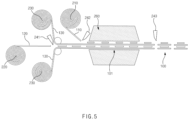
- FIG. 5 is a schematic view illustrating an apparatus for manufacturing a unit cell
- FIGS. 6 and 7 are views illustrating an example of a stacked structure of a cell stack
- FIG. 8 is a schematic view illustrating an example of a method for manufacturing a bonding part.
- the method for manufacturing the electrode assembly includes a process (S10) of preparing a cell stack 11 and a process (S20) forming a bonding part 12.
- the process (S10) of preparing the cell stack 11 may include a process (S11) of preparing unit cells 100 and a process (S12) of stacking the unit cells 100.
- a separator unwinder 230 may unwind a separator roll mounted thereon to unwind a sheet-shaped separator 1.
- the separator unwinder 230 may be provided in a pair, and the sheet-shaped separators 1 unwound from the pair of separator unwinders 230 may be aligned side by side to face each other.
- the electrode unwinders 210 and 220 may unwind the electrode roll mounted thereon to unwind the sheet-shaped electrodes 110 and 120.
- the electrode unwinder 230 may be provided in a pair.
- the sheet-shaped first electrode 110 unwound from one electrode unwinder 210 may be cut into the first electrode 110 having a predetermined width by a cutter 242 and may be disposed at regular intervals on one sheet-shaped separator 130.
- the sheet-shaped second electrode 120 unwound from the other electrode unwinder 220 may be cut into the second electrode 120 having a predetermined width by a cutter 241 and may be disposed at regular intervals on the other sheet-shaped separator 130. In this process, the second electrode 120 may be cut to be longer than the first electrode 110.
- the second electrode 120 may be disposed at regular intervals between the pair of sheet-shaped separators 130, and the first electrode 110 may be disposed at regular intervals on the upper separator 130 of the pair of sheet-shaped separators 130.
- the first electrode 110 and the second electrode 120 are disposed oppositely.
- the electrodes 110 and 120 may be already manufactured in the previous process, and the previously manufactured electrodes 110 and 120 may be disposed on the separator 130 by a transfer device (not shown) such as a pick and place device.
- the electrode stack 101 in which the sheet-shaped separator 130 and the electrodes 110 and 120 having the predetermined width are alternately stacked, may be formed.
- the electrode stack 101 may be laminated by a lamination device 260. That is, the lamination device 260 may laminate the separator 130 and the electrodes 110 and 120 of the electrode stack 101 to each other.
- the lamination device 260 may include a heater that heats the electrode stack 101 and a pressing roller (not shown) that presses the electrode stack 101.
- the configuration of the lamination device 260 is not limited thereto and may vary as necessary.
- the laminated electrode stack 101 may be cut into the unit cells 100 by the cutter 243.
- the sheet-shaped separator 130 of the laminated electrode stack 101 may be cut into the separator 130 having a predetermined width by the cutter 243.
- the separator 130 may be cut to be longer than the second electrode 120.
- a length at which the separator 130 protrudes outward than the second electrode 120 in the unit cell 100 may be 0.7 times or more and 2.4 times or less the height of the cell stack 11 to be manufactured later.
- a length at which the separator 130 protrudes outward than the second electrode 120 in the unit cell 100 may be 1.25 times or more and 1.88 times or less the height of the cell stack 11 to be manufactured later.
- the unit cell 100 may be prepared. However, this is only an exemplary method, and it is possible for the unit cell 100 to be prepared by other methods.
- the plurality of unit cells 100 may be stacked.
- one type of unit cell 100 may be stacked repeatedly, or as illustrated in FIG. 7 , two or more types of unit cells 100a and 100b may be stacked in a given order.
- the unit cell 100 may have a four-layer structure in which the electrodes 110 and 120 and the separators 130 are alternately stacked.
- the unit cell 100 may have a four-layer structure in which a separator 130, a second electrode 120, a separator 130, and a first electrode 110 are sequentially stacked.
- the first type of unit cell 100a may have a six-layer structure in which a separator 130, a first electrode 110, a separator 130, a second electrode 120, a separator 130, and a first electrode 110 are sequentially stacked
- the second type of unit cells 100b may have a six-layer structure in which a separator 130, a second electrode 120, a separator 130, a first electrode 110, a separator 130, and a second electrode 120 are sequentially stacked. Therefore, when the first type of unit cell 100a and the second type of unit cells 100b are stacked one by one, the structure in which the four-layer structure is repeatedly arranged three times may be formed.
- the plurality of unit cells 100 may be stacked to manufacture the cell stack 11 in which the first electrode 110 and the second electrode 120 are alternately stacked with the separator 130 therebetween.
- the electrodes 110 and 120 may be disposed on the one outermost side of the cell stack 11, and the separator 130 may be disposed at the other outermost side. However, it is not limited thereto, and the separator 130 may be disposed, or the electrodes 110 and 120 may be disposed at both the outermost sides of the cell stack 11 by additionally stacking sub-unit cells (not shown) on the plurality of unit cells 100. Since this is a well-known technique, a detailed description thereof will be omitted.
- a pair of rolls 270 may be used as illustrated in FIG. 8 .
- Each of the rolls 270 may rotate around a rotation axis parallel to a full-length direction of the cell stack 11.
- Each of the rolls 270 may be a single roll that is formed to be long in the full-length direction of the cell stack 11.
- each of the rolls 270 may include a plurality of sub-heating rolls disposed at predetermined intervals in the full-length direction of the cell stack 11.
- a plurality of bonding parts 12 may be formed at predetermined intervals in the full-length direction of the cell stack 11.
- the plurality of separators 130 may be bonded to each other while passing between the pair of rolls 270 of which at least one is heated.
- edges of the plurality of separators 130 protruding outward in the width direction than the negative electrode 160 may pass between the pair of rolls 270 and be bonded to each other. At least one of the pair of rolls 270 may press the plurality of separators 130 while being heated to a temperature that is sufficiently higher than room temperature. As a result, the edges of the plurality of separators 130 may be bonded by hot forming to form the bonding part 12.
- the pair of rolls 270 may include a first roll 271 and a second roll 282.
- a diameter of the first roll 271 may be less than that of the second roll 272.
- the plurality of separators 130 may be rolled toward the first roll 271 while being bonded to each other. That is, while the bonding part 12 is formed, the bonding part 12 may be folded toward the cell stack 11.
- a rotation speed of each of the rolls 271 and 272 and a movement path of a rotation axis of each of the rolls 271 and 272 may be appropriately set.
- the second roll 272 may rotate and move along an outer circumference of the first roll 271.
- first roll 271 and the second roll 272 may rotate and move toward the cell stack 11.
- an inner end of the bonding part 12 may be formed as close to the cell stack 11 as possible.
- the inner end of the bonding part 12 may represent a boundary between the second area 132 (see FIG. 2 ) and the third area 133 of the separator 130.
- the folded bonding part 12 protrudes outward than the cell stack 11 in the stacking direction of the cell stack 11, it may be possible to cut a portion of an end side of the bonding part 12.
- FIG. 9 is a schematic view illustrating another example of the method for manufacturing a bonding part.
- a pair of rolls 270 having the same or similar diameters may be used as illustrated in FIG. 9 .
- the plurality of separators 130 and more specifically, edges of the plurality of separators 130 protruding outward in the width direction than the negative electrode 160 may pass between the pair of rolls 270 and be bonded to each other.
- the pair of rolls 270 may move toward the cell stack 11 with the edges of the gathered separators 130 therebetween.
- the fixing jig (not shown) configured to gather the edges of the plurality of separators 130 protruding outward than the negative electrode 160 is used.
- Each of the rolls 270 may rotate around a rotation axis parallel to a full-length direction of the cell stack 11. Each roll 270 may rotate and move in the full-width direction of the cell stack 11.
- the pair of rolls 270 may move toward the cell stack 11 to bond the plurality of separators 130 to each other, and thus, the inner end of the bonding part 12 may be formed as close to the cell stack 11 as possible.
- an increase in width of the electrode assembly 10 caused by the third area 133 of the separator 132 may be minimized, and energy density of the electrode assembly 10 may be improved.
- the process of folding the bonding part 12 toward the cell stack 11 may be additionally performed.
- Electrode assembly 11 Cell stack 12: Bonding part 100: Unit cell 110: First electrode 120: Second electrode 130: Separator 131: First area 132: Second area 133: Third area 270: Roll 271: First roll 272: Second roll
Landscapes
- Engineering & Computer Science (AREA)
- Manufacturing & Machinery (AREA)
- Chemical & Material Sciences (AREA)
- Chemical Kinetics & Catalysis (AREA)
- Electrochemistry (AREA)
- General Chemical & Material Sciences (AREA)
- Secondary Cells (AREA)
- Cell Separators (AREA)
Abstract
Description
- The present application claims the benefit of the priority of
Korean Patent Application Nos. 10-2022-0108707, filed on August 29, 2022 10-2023-0109253, filed on August 21, 2023 - The present invention relates to a method for manufacturing an electrode assembly for a secondary battery, and an electrode assembly manufactured thereby.
- In recent years, the price of energy sources increases due to the depletion of fossil fuels, the interest in environmental pollution is amplified, and the demand for eco-friendly alternative energy sources is becoming an indispensable factor for future life. Accordingly, studies on various power generation technologies such as solar power, wind power, and tidal power are continuing, and power storage devices such as batteries for more efficiently using the generated electrical energy are also of great interest.
- Furthermore, as technology development and demand for electronic mobile devices and electric vehicles using batteries increase, the demands for secondary batteries as energy sources are rapidly increasing. Thus, many studies on batteries which are capable of meeting various demands have been conducted.
- The secondary batteries are classified into cylindrical batteries and prismatic batteries, in which an electrode assembly is embedded in a cylindrical or prismatic metal can, and pouch-type batteries, in which an electrode assembly is embedded in a pouch-type case made of an aluminum laminate sheet according to shapes of battery cases.
- In addition, the electrode assembly may be classified into various types depending on their manufacturing methods. For example, the electrode assembly may be classified into a simple stack type in which a plurality of electrodes and separators are stacked alternately, a lamination & stack type in which unit cells, in which electrodes and separators are laminated are stacked, a jelly-roll type in which an electrode sheet and a separator sheet are wound together, a stack & folding type in which a separator sheet, in which unit cells are stacked, is folded, a z-folding type in which a separator sheet, in which a plurality of electrodes are stacked, is folded in a zigzag shape, and the like.
- Particularly, the lamination & stack type electrode assembly has an advantage of being of high quality and being manufactured quickly. However, the lamination & stack type electrode assembly has no or weak adhesive force between the unit cells, and thus, there is a risk that alignment between the unit cells is misaligned.
- In addition, there is a risk that the separator is folded due to external force or is shrunk due to heat to cause direct short-circuit between the positive electrode and the negative electrode.
- An object of the present invention for solving the above problems is to provide an electrode assembly, which prevents short circuit between electrodes having opposite polarities from occurring due to bonding between separators, and a method for manufacturing the same.
- An object of the present invention for solving the above problems is to provide an electrode assembly in which bonding between separators is easily performed and which has high energy density, and a method of manufacturing the same.
- A method for manufacturing an electrode assembly according to an embodiment of the present invention includes: preparing a cell stack, in which a first electrode and a second electrode having a width greater than that of the first electrode are alternately stacked with a separator therebetween; and forming a bonding part that is folded toward the cell stack by bonding the plurality of separators protruding outward than the first electrode and the second electrode to each other.
- In the forming of the bonding part, the plurality of separators may pass between a first roll and a second roll, of which at least one is heated, and be bonded to each other.
- The first roll may have a diameter less than that of the second roll. The plurality of separators may be bonded to each other to be rolled toward the first roll.
- The preparing of the cell stack may include: preparing unit cells in which the sum of the number of first electrodes and the number of second electrodes are the same as the number of separators; and stacking the unit cells. In each of the unit cells, a length at which the separator may protrude outward than the second electrode is 1.25 times or more a height of the cell stack.
- In the unit cell, a length at which the separator may protrude outward than the second electrode is 1.88 times or less the height of the cell stack.
- In the stacking of the unit cells, one type of unit cell may be repeatedly stacked, or two types of unit cells may be stacked in a predetermined order.
- The bonding part may be disposed at each of both sides of the cell stack in a width direction to extend in a full-length direction of the cell stack.
- An electrode assembly according to an embodiment of the present invention includes: a cell stack, in which a first electrode and a second electrode having a width greater than that of the first electrode are alternately stacked with a separator therebetween; and a bonding part that is folded toward the cell stack by bonding the plurality of separators protruding outward than the first electrode and the second electrode to each other.
- A length at which the outermost separator of the plurality of separators protrudes outward than the second electrode may be 1.25 times or more the height of the cell stack.
- A length at which the outermost separator protrudes outward than the second electrode may be 1.88 times or less the height of the cell stack.
- The bonding part may be disposed at each of both sides of the cell stack in a width direction to extend in a full-length direction of the cell stack.
- The bonding part may not protrude outward than the cell stack in the stacking direction of the cell stack.
- A proximal end of the bonding part may be disposed to correspond to a central portion in the stacking direction of the cell stack.
- The separator may include: a first area that overlaps the first electrode or the second electrode in the stacking direction of the cell stack; a second area configured to constitutes the bonding part; and a third area configured to connect the first area to the second area. An inclination of the third area may be steeper at the separator disposed at each of both outer sides.
- According to the preferred embodiment of the present invention, the first electrode and the second electrode may be prevented from being short-circuited by the bonding part provided by bonding the separators to each other.
- In addition, the separator may protrude sufficiently longer than the negative electrode to easily form the bonding part, thereby preventing the bonding part from being ruptured or disconnected.
- In addition, since the bonding part is folded, the full width of the electrode assembly may be prevented from unnecessarily increasing to increase in energy density of the electrode assembly.
- In addition, since the inner end of the bonding part is disposed to be as close as possible to the cell stack by the roll, the increase in width of the electrode assembly by the separator may be minimized, and the energy density of the electrode assembly may be improved.
- In addition, the effects that are obvious to those skilled in the art may be predicted from the configurations according to the embodiment of the present invention.
- The following drawings attached in this specification illustrate a preferred embodiment of the present invention and function to make further understood the technical spirit of the present invention along with the detailed description of the invention, and thus, the present invention should not be construed as being limited to only the drawings.
-
FIG. 1 is a perspective view illustrating an electrode assembly according to an embodiment of the present invention. -
FIG. 2 is a cross-sectional view illustrating the electrode assembly according to an embodiment of the present invention. -
FIG. 3 is a cross-sectional view illustrating a state in which a bonding part ofFIG. 2 is formed. -
FIG. 4 is a flowchart illustrating a method for manufacturing an electrode assembly according to another embodiment of the present invention. -
FIG. 5 is a schematic view illustrating an apparatus for manufacturing a unit cell. -
FIGS. 6 and7 are views illustrating an example of a stacked structure of a cell stack. -
FIG. 8 is a schematic view illustrating an example of a method for manufacturing a bonding part. -
FIG. 9 is a schematic view illustrating another example of a method for manufacturing a bonding part. - Hereinafter, preferred embodiments of the present invention will be described in detail with reference to the accompanying drawings so that those of ordinary skill in the art may easily carry out the present invention. However, the present invention may be implemented in several different forms and is not limited or restricted by the following examples.
- In order to clearly explain the present invention, detailed descriptions of portions that are irrelevant to the description or related known technologies that may unnecessarily obscure the gist of the present invention have been omitted, and in the present specification, reference symbols are added to components in each drawing. In this case, the same or similar reference numerals are assigned to the same or similar elements throughout the specification.
- Also, terms or words used in this specification and claims should not be restrictively interpreted as ordinary meanings or dictionary-based meanings, but should be interpreted as meanings and concepts conforming to the scope of the present invention on the basis of the principle that an inventor may properly define the concept of a term to describe and explain his or her invention in the best ways.
-
FIG. 1 is a perspective view illustrating an electrode assembly according to an embodiment of the present invention, andFIG. 2 is a cross-sectional view illustrating the electrode assembly according to an embodiment of the present invention. - An
electrode assembly 10 according to an embodiment of the present invention may include acell stack 11, in whichelectrodes separator 130 therebetween, and abonding part 12 in which a plurality ofseparators 130 protruding outward than theelectrodes - Each of the
electrodes electrodes FIG. 1 ) of thecell stack 11 and a pair of short sides extending in a full-width direction (e.g., direction parallel to an X-axis inFIG. 1 ) of thecell stack 11. - The
electrodes first electrode 110 and asecond electrode 120. Thesecond electrode 120 may have a width greater than that of thefirst electrode 110. Thefirst electrode 110 and thesecond electrode 120 may be alternately stacked with theseparator 130 therebetween. For example, thefirst electrode 110 may be a positive electrode, and thesecond electrode 120 may be a negative electrode. - The
separators 130 may protrude outward than theelectrodes bonding part 12. Thebonding part 12 may be formed by bonding edges of theseparators 130 to each other. In more detail, thebonding part 12 may be formed by bonding both the edges of theseparator 130 in a width direction to each other. Thus, thebonding part 12 may be disposed at both sides of thecell stack 11 in the width direction. - As a result, short circuit between the long sides of the
electrodes electrode assembly 10 is longer than a full width (for example, a long cell), there is a risk that the edge in the width direction of theseparator 130 is folded. Therefore, it may be effective to prevent the above concern if thebonding part 12 is disposed at each of both the sides in the width direction of thecell stack 11. - The
bonding part 12 may be provided to be long in the full-length direction of thecell stack 11. However, it is not limited thereto, and thebonding part 12 may be provided in plurality at predetermined intervals in the full-length direction of thecell stack 11. - The
bonding part 12 may be folded toward thecell stack 11. In more detail, thebonding part 12 may be folded toward thecell stack 11 at least once. For example, thebonding part 12 may be folded once as illustrated inFIG. 2 . As another example, thebonding part 12 may be double side folded (DSF). - As a result, the full width of the
electrode assembly 10 may be prevented from unnecessarily increasing, and thus, the energy density may more increase. In addition, when theelectrode assembly 10 is accommodated in a pouch-type battery case (not shown), an interference of thebonding part 12 with the battery case may be minimized. In addition, when compared to a case in which thebonding part 12 is provided to be short so as not to be folded, bonding force between the plurality of separators that forms thebonding part 12 may be strengthened. - The folded
bonding part 12 may not protrude outward than thecell stack 11 with respect to the stacking direction of thecell stack 11. In more detail, the entire foldedbonding part 12 may overlap thecell stack 11 in the full-width direction of thecell stack 11. For example, when thebonding part 12 is folded once as illustrated inFIG. 2 , an end of thebonding part 12 may not protrude outward than the uppermost or lowermost end of thecell stack 11. - As a result, the height of the
electrode assembly 10 may be prevented from unnecessarily increasing, and thus, the energy density may more increase. In addition, when theelectrode assembly 10 is accommodated in a pouch-type battery case (not shown), an interference of thebonding part 12 with the battery case may be minimized. - Each of the
separators 130 may include afirst area 131 overlapping thefirst electrode 110 or thesecond electrode 120 in the stacking direction of thecell stack 11, asecond area 132 that forms thebonding part 12, and athird area 133 connecting thefirst area 131 to thesecond area 132. Thefirst area 131 may be parallel to theelectrodes third areas 133 of the plurality ofseparators 130 may be disposed to be inclined in a direction that approaches each other toward the outside. - All the
separators 130 of thecell stack 11 may be bonded at once to form thebonding part 12. The proximal end of thebonding part 12 may be disposed to correspond to a central portion in the stacking direction of the cell stack 11 (for example, direction parallel to a Z-axis inFIG. 1 ). Thus, an inclination of thethird area 133 may be steeper at theseparator 130 disposed at each of both outer sides. The longer theseparator 130 is disposed on both outer sides, the longer thethird area 133 may be formed to be long. - If the proximal end of the
bonding part 12 is disposed eccentrically downward with respect to the stacking direction of thecell stack 11, there is a problem in that thethird area 133 of theuppermost separator 130 has to be very long. That is, the proximal end of thebonding part 12 may be disposed to correspond to the central portion of thecell stack 11, and thus, a length of theoutermost separator 130 required to form thebonding part 12 may be reduced. Theoutermost separator 130 may be aseparator 130 disposed at the outermost side of thecell stack 11 or aseparator 130 in which theelectrodes cell stack 11 are stacked. - Since a length of the
third area 133 is provided to be long as theseparator 130 is disposed at each of both the outer sides, the length of theoutermost separator 130 may have to be sufficiently long to easily form thebonding part 12. In addition, as the height of thecell stack 11 increases, the length of theoutermost separator 130 required to form thebonding part 12 has to also increase. - Thus, the length of the
outermost separator 130 of the plurality ofseparators 130 of theelectrode assembly 10 protruding outward than thesecond electrode 120 may be 0.7 times or more than the height h of thecell stack 11. As a result, thebonding part 12 may be easily formed, and thethird area 133 of theoutermost separator 130 may be prevented from being ruptured or disconnected after thebonding part 12 is formed. - In more detail, when viewed in the full-width direction of the
cell stack 11 as illustrated inFIG. 2 , the length at which theoutermost separator 130 protrudes outward than thesecond electrode 120 may be 0.7 times or more, preferably, 1.25 times or more the height h of thecell stack 11. - The length at which each
separator 130 protrudes outward than thesecond electrode 120 may mean the sum of the length of thebonding part 12 and the length of thethird area 133 of eachseparator 130. -
FIG. 3 is a cross-sectional view illustrating a state in which the bonding part ofFIG. 2 is formed. - Before forming the
bonding part 12, that theoutermost separator 130 of thecell stack 11 is formed to have a length that is different from that of theother separators 130 may be inefficient in terms of manufacturing. Thus, as illustrated inFIG. 3 , before forming thebonding part 12, the plurality ofseparators 130 provided in thecell stack 11 may have the same width or similar widths. - Before forming the
bonding part 12, the length d of theseparator 130 protruding outward than thecell stack 11 beyond thesecond electrode 120 may be 0.7 times or more the height h of thecell stack 11, preferably 1.25 times or more. As a result, thebonding part 12 may be easily formed. - In addition, before forming the
bonding part 12, the length d of theseparator 130 protruding outward than thecell stack 11 beyond thesecond electrode 120 may be 2.4 times or less the height h of thecell stack 11, preferably 1.88 times or less. As a result, theseparator 130 may be prevented from being formed to be long unnecessarily, and manufacturing costs of thecell stack 11 may be reduced. - That is, before forming the
bonding part 12, the length d of theseparator 130 protruding outward than thecell stack 11 beyond thesecond electrode 120 may be 0.7 times to 2.4 times the height h of thecell stack 11, preferably 1.25 times to 1.88 times. - For example, the height h of the
cell stack 11 may be approximately 8 mm, and the length of eachseparator 130 protruding outward than thesecond electrode 120 may be 10 mm to 15 mm. - The
cell stack 11 may be formed by stacking a plurality ofunit cells 100. That is, thecell stack 11 may be a lamination and stack (L&S) type. In eachunit cell 100, the sum of the number offirst electrodes 110 andsecond electrodes 120 may be equal to the number ofseparators 130. For example, as illustrated inFIG. 3 , each unit cell may include onefirst electrode 110, onesecond electrode 120, and twoseparators 130. - The
electrodes separator 130, which are provided in eachunit cell 100, may be in a laminated state. - Adhesion force between the
adjacent unit cells 100 may be weaker than that between theelectrodes separator 130 within eachunit cell 100. In more detail, the adhesive force between each of theelectrodes unit cell 100 and theseparator 130 of theother unit cell 100 may be weaker than that between each of theelectrodes separator 130 within oneunit cell 100. Based on these characteristics, it may be determined that thecell stack 11 is the lamination and stack (L&S) type rather than the simple stacked type. - Therefore, in each
unit cell 100, the length d of theseparator 130 protruding outward than thesecond electrode 120 may be 0.7 times or more, preferably 1.25 times or more the height h of thecell stack 11 in which the plurality ofunit cells 100 are stacked. In addition, in eachunit cell 100, the length d of theseparator 130 protruding outward than thecell stack 11 beyond thesecond electrode 120 may be 2.4 times or less, preferably 1.88 times or less the height h of thecell stack 11. - That is, in each
unit cell 100, the length d of theseparator 130 protruding outward than thecell stack 11 beyond thesecond electrode 120 may be 0.7 times to 2.4 times, preferably 1.25 times to 1.88 times the height h of thecell stack 11, in which the plurality ofunit cells 100 are stacked. -
FIG. 4 is a flowchart illustrating a method for manufacturing an electrode assembly according to another embodiment of the present invention,FIG. 5 is a schematic view illustrating an apparatus for manufacturing a unit cell,FIGS. 6 and7 are views illustrating an example of a stacked structure of a cell stack, andFIG. 8 is a schematic view illustrating an example of a method for manufacturing a bonding part. - Hereinafter, a method for manufacturing an
electrode assembly 10 described above will be described as another embodiment of the present invention. - The method for manufacturing the electrode assembly (hereinafter, referred to as 'manufacturing method') according to another embodiment of the present invention includes a process (S10) of preparing a
cell stack 11 and a process (S20) forming abonding part 12. - The process (S10) of preparing the
cell stack 11 may include a process (S11) of preparingunit cells 100 and a process (S12) of stacking theunit cells 100. - Hereinafter, the process (S11) of preparing the
unit cells 100 will be described with reference toFIG. 5 . - A
separator unwinder 230 may unwind a separator roll mounted thereon to unwind a sheet-shaped separator 1. - The
separator unwinder 230 may be provided in a pair, and the sheet-shaped separators 1 unwound from the pair ofseparator unwinders 230 may be aligned side by side to face each other. - The electrode unwinders 210 and 220 may unwind the electrode roll mounted thereon to unwind the sheet-shaped
electrodes - The
electrode unwinder 230 may be provided in a pair. The sheet-shapedfirst electrode 110 unwound from oneelectrode unwinder 210 may be cut into thefirst electrode 110 having a predetermined width by acutter 242 and may be disposed at regular intervals on one sheet-shapedseparator 130. The sheet-shapedsecond electrode 120 unwound from theother electrode unwinder 220 may be cut into thesecond electrode 120 having a predetermined width by acutter 241 and may be disposed at regular intervals on the other sheet-shapedseparator 130. In this process, thesecond electrode 120 may be cut to be longer than thefirst electrode 110. - For example, the
second electrode 120 may be disposed at regular intervals between the pair of sheet-shapedseparators 130, and thefirst electrode 110 may be disposed at regular intervals on theupper separator 130 of the pair of sheet-shapedseparators 130. However, it is not limited thereto, and it is also possible that thefirst electrode 110 and thesecond electrode 120 are disposed oppositely. - In addition, unlike illustrated in
FIG. 5 , theelectrodes electrodes separator 130 by a transfer device (not shown) such as a pick and place device. - As a result, the
electrode stack 101, in which the sheet-shapedseparator 130 and theelectrodes - The
electrode stack 101 may be laminated by alamination device 260. That is, thelamination device 260 may laminate theseparator 130 and theelectrodes electrode stack 101 to each other. - For example, the
lamination device 260 may include a heater that heats theelectrode stack 101 and a pressing roller (not shown) that presses theelectrode stack 101. However, the configuration of thelamination device 260 is not limited thereto and may vary as necessary. - The
laminated electrode stack 101 may be cut into theunit cells 100 by thecutter 243. In more detail, the sheet-shapedseparator 130 of thelaminated electrode stack 101 may be cut into theseparator 130 having a predetermined width by thecutter 243. In this process, theseparator 130 may be cut to be longer than thesecond electrode 120. A length at which theseparator 130 protrudes outward than thesecond electrode 120 in theunit cell 100 may be 0.7 times or more and 2.4 times or less the height of thecell stack 11 to be manufactured later. Preferably, a length at which theseparator 130 protrudes outward than thesecond electrode 120 in theunit cell 100 may be 1.25 times or more and 1.88 times or less the height of thecell stack 11 to be manufactured later. - Thus, the
unit cell 100 may be prepared. However, this is only an exemplary method, and it is possible for theunit cell 100 to be prepared by other methods. - Hereinafter, the process (S12) of stacking the
unit cells 100 will be described with reference toFIGS. 6 and7 . - When the process (S12) of stacking the
unit cells 100 is performed, the plurality ofunit cells 100 may be stacked. In more detail, as illustrated inFIG. 6 , one type ofunit cell 100 may be stacked repeatedly, or as illustrated inFIG. 7 , two or more types ofunit cells - As illustrated in
FIG. 6 , when the one type ofunit cell 100 is repeatedly stacked, theunit cell 100 may have a four-layer structure in which theelectrodes separators 130 are alternately stacked. For example, theunit cell 100 may have a four-layer structure in which aseparator 130, asecond electrode 120, aseparator 130, and afirst electrode 110 are sequentially stacked. - As illustrated in
FIG. 7 , when the two or more types ofunit cells unit cells electrodes separator 130 are alternately stacked, or a structure in which the four-layer structure is repeatedly disposed may be formed. - For example, the first type of
unit cell 100a may have a six-layer structure in which aseparator 130, afirst electrode 110, aseparator 130, asecond electrode 120, aseparator 130, and afirst electrode 110 are sequentially stacked, and the second type ofunit cells 100b may have a six-layer structure in which aseparator 130, asecond electrode 120, aseparator 130, afirst electrode 110, aseparator 130, and asecond electrode 120 are sequentially stacked. Therefore, when the first type ofunit cell 100a and the second type ofunit cells 100b are stacked one by one, the structure in which the four-layer structure is repeatedly arranged three times may be formed. - Thus, the plurality of
unit cells 100 may be stacked to manufacture thecell stack 11 in which thefirst electrode 110 and thesecond electrode 120 are alternately stacked with theseparator 130 therebetween. - When forming the
cell stack 11 using only theunit cells 100, theelectrodes cell stack 11, and theseparator 130 may be disposed at the other outermost side. However, it is not limited thereto, and theseparator 130 may be disposed, or theelectrodes cell stack 11 by additionally stacking sub-unit cells (not shown) on the plurality ofunit cells 100. Since this is a well-known technique, a detailed description thereof will be omitted. - Hereinafter, the process (S20) of forming the
bonding part 12 will be described with reference toFIG. 8 . - As an example of the method for forming the
bonding part 12, a pair ofrolls 270 may be used as illustrated inFIG. 8 . - Each of the
rolls 270 may rotate around a rotation axis parallel to a full-length direction of thecell stack 11. Each of therolls 270 may be a single roll that is formed to be long in the full-length direction of thecell stack 11. However, it is not limited thereto, and each of therolls 270 may include a plurality of sub-heating rolls disposed at predetermined intervals in the full-length direction of thecell stack 11. In this case, a plurality ofbonding parts 12 may be formed at predetermined intervals in the full-length direction of thecell stack 11. - In the process (S20) of forming the
bonding part 12, the plurality ofseparators 130 may be bonded to each other while passing between the pair ofrolls 270 of which at least one is heated. - In more detail, edges of the plurality of
separators 130 protruding outward in the width direction than the negative electrode 160 may pass between the pair ofrolls 270 and be bonded to each other. At least one of the pair ofrolls 270 may press the plurality ofseparators 130 while being heated to a temperature that is sufficiently higher than room temperature. As a result, the edges of the plurality ofseparators 130 may be bonded by hot forming to form thebonding part 12. - In this process, it is obvious that a fixing jig (not shown) configured to gather the edges of the plurality of
separators 130 protruding outward than the negative electrode 160 is used. - The pair of
rolls 270 may include afirst roll 271 and a second roll 282. A diameter of thefirst roll 271 may be less than that of thesecond roll 272. Thus, the plurality ofseparators 130 may be rolled toward thefirst roll 271 while being bonded to each other. That is, while thebonding part 12 is formed, thebonding part 12 may be folded toward thecell stack 11. - In order to easily fold the
folding part 12, a rotation speed of each of therolls rolls second roll 272 may rotate and move along an outer circumference of thefirst roll 271. Thus, there is an advantage that a separate process for folding thebonding part 12 is unnecessary. - In addition, the
first roll 271 and thesecond roll 272 may rotate and move toward thecell stack 11. Thus, an inner end of thebonding part 12 may be formed as close to thecell stack 11 as possible. The inner end of thebonding part 12 may represent a boundary between the second area 132 (seeFIG. 2 ) and thethird area 133 of theseparator 130. As a result, an increase in width of theelectrode assembly 10 caused by thethird area 133 of theseparator 132 may be minimized, and energy density of theelectrode assembly 10 may be improved. - If the folded
bonding part 12 protrudes outward than thecell stack 11 in the stacking direction of thecell stack 11, it may be possible to cut a portion of an end side of thebonding part 12. -
FIG. 9 is a schematic view illustrating another example of the method for manufacturing a bonding part. - As another example of the method for forming the
bonding part 12, a pair ofrolls 270 having the same or similar diameters may be used as illustrated inFIG. 9 . - The plurality of
separators 130, and more specifically, edges of the plurality ofseparators 130 protruding outward in the width direction than the negative electrode 160 may pass between the pair ofrolls 270 and be bonded to each other. - In more detail, the pair of
rolls 270 may move toward thecell stack 11 with the edges of the gatheredseparators 130 therebetween. Here, it is obvious that the fixing jig (not shown) configured to gather the edges of the plurality ofseparators 130 protruding outward than the negative electrode 160 is used. - Each of the
rolls 270 may rotate around a rotation axis parallel to a full-length direction of thecell stack 11. Eachroll 270 may rotate and move in the full-width direction of thecell stack 11. - As described above, the pair of
rolls 270 may move toward thecell stack 11 to bond the plurality ofseparators 130 to each other, and thus, the inner end of thebonding part 12 may be formed as close to thecell stack 11 as possible. As a result, an increase in width of theelectrode assembly 10 caused by thethird area 133 of theseparator 132 may be minimized, and energy density of theelectrode assembly 10 may be improved. Thereafter, the process of folding thebonding part 12 toward thecell stack 11 may be additionally performed. - The above-disclosed subject matter is to be considered illustrative, and not restrictive, and the appended claims are intended to cover all such modifications, enhancements, and other embodiments, which fall within the true spirit and scope of the present invention.
- Thus, the embodiment of the present invention is to be considered illustrative, and not restrictive, and the technical spirit of the present invention is not limited to the foregoing embodiment.
- Therefore, the scope of the present invention is defined not by the detailed description of the invention but by the appended claims, and all differences within the scope will be construed as being included in the present invention.
-
10: Electrode assembly 11: Cell stack 12: Bonding part 100: Unit cell 110: First electrode 120: Second electrode 130: Separator 131: First area 132: Second area 133: Third area 270: Roll 271: First roll 272: Second roll
Claims (14)
- A method for manufacturing an electrode assembly, the method comprising:preparing a cell stack, in which a first electrode and a second electrode having a width greater than that of the first electrode are alternately stacked with a separator therebetween; andforming a bonding part that is folded toward the cell stack by bonding the plurality of separators protruding outward than the first electrode and the second electrode to each other.
- The method of claim 1, wherein, in the forming of the bonding part, the plurality of separators pass between a first roll and a second roll, of which at least one is heated, and are bonded to each other.
- The method of claim 2, wherein the first roll has a diameter less than that of the second roll, and
the plurality of separators are bonded to each other to be rolled toward the first roll. - The method of claim 1, wherein the preparing of the cell stack comprises:preparing unit cells in which the sum of the number of first electrodes and the number of second electrodes are the same as the number of separators; andstacking the unit cells,wherein, in each of the unit cells, a length at which the separator protrudes outward than the second electrode is 1.25 times or more a height of the cell stack.
- The method of claim 4, wherein, in the unit cell, a length at which the separator protrudes outward than the second electrode is 1.88 times or less the height of the cell stack.
- The method of claim 4, wherein, in the stacking of the unit cells,one type of unit cell is repeatedly stacked, ortwo types of unit cells are stacked in a predetermined order.
- The method of claim 1, wherein the bonding part is disposed at each of both sides of the cell stack in a width direction to extend in a full-length direction of the cell stack.
- An electrode assembly comprising:a cell stack, in which a first electrode and a second electrode having a width greater than that of the first electrode are alternately stacked with a separator therebetween; anda bonding part that is folded toward the cell stack by bonding the plurality of separators protruding outward than the first electrode and the second electrode to each other.
- The electrode assembly of claim 8, wherein a length at which the outermost separator of the plurality of separators protrudes outward than the second electrode is 1.25 times or more the height of the cell stack.
- The electrode assembly of claim 9, wherein a length at which the outermost separator protrudes outward than the second electrode is 1.88 times or less the height of the cell stack.
- The electrode assembly of claim 8, wherein the bonding part is disposed at each of both sides of the cell stack in a width direction to extend in a full-length direction of the cell stack.
- The electrode assembly of claim 8, wherein the bonding part does not protrude outward than the cell stack in the stacking direction of the cell stack.
- The electrode assembly of claim 8, wherein a proximal end of the bonding part is disposed to correspond to a central portion in the stacking direction of the cell stack.
- The electrode assembly of claim 8, wherein the separator comprises:a first area that overlaps the first electrode or the second electrode in the stacking direction of the cell stack;a second area configured to constitutes the bonding part; anda third area configured to connect the first area to the second area,wherein an inclination of the third area is steeper at the separator disposed at each of both outer sides.
Applications Claiming Priority (3)
| Application Number | Priority Date | Filing Date | Title |
|---|---|---|---|
| KR20220108707 | 2022-08-29 | ||
| KR1020230109253A KR20240031065A (en) | 2022-08-29 | 2023-08-21 | Manufacturing method of electrode assembly and the electrode assembly |
| PCT/KR2023/012520 WO2024049096A1 (en) | 2022-08-29 | 2023-08-24 | Electrode assembly manufacturing method and electrode assembly |
Publications (2)
| Publication Number | Publication Date |
|---|---|
| EP4560750A1 true EP4560750A1 (en) | 2025-05-28 |
| EP4560750A4 EP4560750A4 (en) | 2025-05-28 |
Family
ID=90098259
Family Applications (1)
| Application Number | Title | Priority Date | Filing Date |
|---|---|---|---|
| EP23860773.3A Pending EP4560750A4 (en) | 2022-08-29 | 2023-08-24 | Electrode assembly manufacturing method and electrode assembly |
Country Status (5)
| Country | Link |
|---|---|
| US (1) | US20260074268A1 (en) |
| EP (1) | EP4560750A4 (en) |
| JP (1) | JP2025528919A (en) |
| CN (1) | CN119836702A (en) |
| WO (1) | WO2024049096A1 (en) |
Family Cites Families (14)
| Publication number | Priority date | Publication date | Assignee | Title |
|---|---|---|---|---|
| JP3606089B2 (en) * | 1999-01-26 | 2005-01-05 | 松下電器産業株式会社 | Method for producing alkaline storage battery |
| US8486160B2 (en) * | 2009-12-17 | 2013-07-16 | Samsung Sdi Co., Ltd. | Rechargeable battery |
| JP5480726B2 (en) * | 2010-06-11 | 2014-04-23 | 日新製鋼株式会社 | Manufacturing method for battery case |
| JP2013206699A (en) * | 2012-03-28 | 2013-10-07 | Tdk Corp | Electrochemical devices |
| EP2958179B1 (en) * | 2013-02-15 | 2017-06-21 | LG Chem, Ltd. | Electrode assembly having improved safety and production method therefor |
| TWI520407B (en) * | 2013-02-15 | 2016-02-01 | Lg化學股份有限公司 | Electrode assembly |
| KR101595643B1 (en) * | 2013-02-15 | 2016-02-18 | 주식회사 엘지화학 | Electrode assembly and cell of polymer lithium secondary battery comprising the same |
| KR101807354B1 (en) * | 2015-05-12 | 2017-12-08 | 주식회사 엘지화학 | Electrode assembly |
| JP2019016494A (en) * | 2017-07-06 | 2019-01-31 | リチウム エナジー アンド パワー ゲゼルシャフト ミット ベシュレンクテル ハフッング ウント コンパニー コマンディトゲゼルシャフトLithium Energy and Power GmbH & Co. KG | Method for manufacturing multilayer electrode body and method for manufacturing power storage element |
| JP6955201B2 (en) * | 2017-08-30 | 2021-10-27 | 株式会社豊田自動織機 | Manufacturing method of bag-shaped separator |
| JP7069625B2 (en) * | 2017-10-06 | 2022-05-18 | 株式会社Gsユアサ | Manufacturing method of power storage element |
| KR102259747B1 (en) * | 2019-05-14 | 2021-06-02 | 주식회사 엘지에너지솔루션 | Electrode assembly and manufacturing method thereof |
| KR102560392B1 (en) | 2021-01-27 | 2023-07-27 | 김기수 | Driving lesson brake system |
| KR20230109253A (en) | 2022-01-13 | 2023-07-20 | 이대균 | Freeness measurement system and method using a photometer |
-
2023
- 2023-08-24 WO PCT/KR2023/012520 patent/WO2024049096A1/en not_active Ceased
- 2023-08-24 EP EP23860773.3A patent/EP4560750A4/en active Pending
- 2023-08-24 CN CN202380062553.7A patent/CN119836702A/en active Pending
- 2023-08-24 US US19/107,865 patent/US20260074268A1/en active Pending
- 2023-08-24 JP JP2025512013A patent/JP2025528919A/en active Pending
Also Published As
| Publication number | Publication date |
|---|---|
| EP4560750A4 (en) | 2025-05-28 |
| WO2024049096A1 (en) | 2024-03-07 |
| US20260074268A1 (en) | 2026-03-12 |
| JP2025528919A (en) | 2025-09-02 |
| CN119836702A (en) | 2025-04-15 |
Similar Documents
| Publication | Publication Date | Title |
|---|---|---|
| EP3866254B1 (en) | Secondary battery having improved current-collecting structure | |
| KR100309604B1 (en) | Lithium secondary battery | |
| EP2882024B1 (en) | Stepped electrode assembly, and secondary battery, battery pack and device comprising same and method for manufacturing same | |
| KR101586121B1 (en) | Lamination device including electrode guide | |
| JP2019091682A (en) | Method of manufacturing laminated secondary battery | |
| EP3416225B1 (en) | Electrode assembly and manufacturing method therefor | |
| KR20140035646A (en) | Cell stacking method for secondary battery and cell stack for using the same | |
| EP3396766A1 (en) | Electrode assembly and method for producing same | |
| US12586808B2 (en) | Apparatus and method for manufacturing unit cells | |
| KR101799570B1 (en) | Electrode Assembly Folded in the Bi-Direction and Lithium Secondary Battery Comprising the Same | |
| KR101590991B1 (en) | Electrode Assembly Having Separators Attached to Each Other and Battery Cell Comprising the Same | |
| JP7570755B2 (en) | Battery cell including electrode tab with stress relief portion formed thereon | |
| JP7648111B2 (en) | Electrode assembly with coating for preventing short circuit | |
| EP4250431A1 (en) | Electrode for lithium secondary battery to which adhesive coating part is added, and method for manufacturing same | |
| KR102950880B1 (en) | Jelly-roll type electrode assembly and secondary battery including the same | |
| EP4560750A1 (en) | Electrode assembly manufacturing method and electrode assembly | |
| EP4174995A1 (en) | Secondary battery manufacturing method and secondary battery | |
| CN220290878U (en) | Device for manufacturing unit cell | |
| EP4621893A1 (en) | Lamination device and electrode assembly manufacturing method | |
| EP4333146B1 (en) | Electrode assembly manufacturing apparatus for preventing separator folding and electrode assembly manufactured using the same | |
| KR101174964B1 (en) | Secondary battery and method for menufacturing electrode assembly thereof | |
| KR20240031065A (en) | Manufacturing method of electrode assembly and the electrode assembly | |
| KR102834336B1 (en) | Electrode assembly and manufacturing method of the same | |
| JP2023547799A (en) | Electrode assembly manufacturing method and its manufacturing device | |
| EP4258400A1 (en) | Electrode assembly lamination roller |
Legal Events
| Date | Code | Title | Description |
|---|---|---|---|
| STAA | Information on the status of an ep patent application or granted ep patent |
Free format text: STATUS: THE INTERNATIONAL PUBLICATION HAS BEEN MADE |
|
| PUAI | Public reference made under article 153(3) epc to a published international application that has entered the european phase |
Free format text: ORIGINAL CODE: 0009012 |
|
| STAA | Information on the status of an ep patent application or granted ep patent |
Free format text: STATUS: REQUEST FOR EXAMINATION WAS MADE |
|
| 17P | Request for examination filed |
Effective date: 20250224 |
|
| A4 | Supplementary search report drawn up and despatched |
Effective date: 20250411 |
|
| AK | Designated contracting states |
Kind code of ref document: A1 Designated state(s): AL AT BE BG CH CY CZ DE DK EE ES FI FR GB GR HR HU IE IS IT LI LT LU LV MC ME MK MT NL NO PL PT RO RS SE SI SK SM TR |
|
| STAA | Information on the status of an ep patent application or granted ep patent |
Free format text: STATUS: EXAMINATION IS IN PROGRESS |
|
| 17Q | First examination report despatched |
Effective date: 20250812 |
|
| DAV | Request for validation of the european patent (deleted) | ||
| DAX | Request for extension of the european patent (deleted) | ||
| GRAP | Despatch of communication of intention to grant a patent |
Free format text: ORIGINAL CODE: EPIDOSNIGR1 |
|
| STAA | Information on the status of an ep patent application or granted ep patent |
Free format text: STATUS: GRANT OF PATENT IS INTENDED |
|
| RIC1 | Information provided on ipc code assigned before grant |
Ipc: H01M 10/04 20060101AFI20260227BHEP Ipc: H01M 10/0585 20100101ALI20260227BHEP |
|
| GRAJ | Information related to disapproval of communication of intention to grant by the applicant or resumption of examination proceedings by the epo deleted |
Free format text: ORIGINAL CODE: EPIDOSDIGR1 |
|
| STAA | Information on the status of an ep patent application or granted ep patent |
Free format text: STATUS: EXAMINATION IS IN PROGRESS |