EP4560676A1 - An electric current knife switch comprising a puffer de-latching mechanism - Google Patents
An electric current knife switch comprising a puffer de-latching mechanism Download PDFInfo
- Publication number
- EP4560676A1 EP4560676A1 EP23212315.8A EP23212315A EP4560676A1 EP 4560676 A1 EP4560676 A1 EP 4560676A1 EP 23212315 A EP23212315 A EP 23212315A EP 4560676 A1 EP4560676 A1 EP 4560676A1
- Authority
- EP
- European Patent Office
- Prior art keywords
- contact
- contact lever
- piston
- electric current
- lever
- Prior art date
- Legal status (The legal status is an assumption and is not a legal conclusion. Google has not performed a legal analysis and makes no representation as to the accuracy of the status listed.)
- Withdrawn
Links
Images






Classifications
-
- H—ELECTRICITY
- H01—ELECTRIC ELEMENTS
- H01H—ELECTRIC SWITCHES; RELAYS; SELECTORS; EMERGENCY PROTECTIVE DEVICES
- H01H33/00—High-tension or heavy-current switches with arc-extinguishing or arc-preventing means
- H01H33/02—Details
- H01H33/04—Means for extinguishing or preventing arc between current-carrying parts
- H01H33/12—Auxiliary contacts on to which the arc is transferred from the main contacts
- H01H33/121—Load break switches
-
- H—ELECTRICITY
- H01—ELECTRIC ELEMENTS
- H01H—ELECTRIC SWITCHES; RELAYS; SELECTORS; EMERGENCY PROTECTIVE DEVICES
- H01H31/00—Air-break switches for high tension without arc-extinguishing or arc-preventing means
- H01H31/003—Earthing switches
-
- H—ELECTRICITY
- H01—ELECTRIC ELEMENTS
- H01H—ELECTRIC SWITCHES; RELAYS; SELECTORS; EMERGENCY PROTECTIVE DEVICES
- H01H33/00—High-tension or heavy-current switches with arc-extinguishing or arc-preventing means
- H01H33/02—Details
- H01H33/04—Means for extinguishing or preventing arc between current-carrying parts
-
- H—ELECTRICITY
- H01—ELECTRIC ELEMENTS
- H01H—ELECTRIC SWITCHES; RELAYS; SELECTORS; EMERGENCY PROTECTIVE DEVICES
- H01H1/00—Contacts
- H01H1/12—Contacts characterised by the manner in which co-operating contacts engage
- H01H1/36—Contacts characterised by the manner in which co-operating contacts engage by sliding
- H01H1/42—Knife-and-clip contacts
-
- H—ELECTRICITY
- H01—ELECTRIC ELEMENTS
- H01H—ELECTRIC SWITCHES; RELAYS; SELECTORS; EMERGENCY PROTECTIVE DEVICES
- H01H31/00—Air-break switches for high tension without arc-extinguishing or arc-preventing means
- H01H31/26—Air-break switches for high tension without arc-extinguishing or arc-preventing means with movable contact that remains electrically connected to one line in open position of switch
- H01H31/28—Air-break switches for high tension without arc-extinguishing or arc-preventing means with movable contact that remains electrically connected to one line in open position of switch with angularly-movable contact
Definitions
- the present invention relates to an electric current switch.
- Electric switches for medium- and high voltage switchgear are subject to electric arcing during current interruption and contact making events. Suppressing the arcs is important to protect the electric switch itself and electric devices connected to the electric switch.
- Effects of arcs may be suppressed by appropriate material selection of arcing contact areas of the connecting parts of the electric switch that can withstand and reduce the arcing. Further, arc-extinction can be provided by application of an appropriate gas onto the arc using a so-called puffer.
- a puffer often includes a piston that moves in a puffer volume for building up a gas pressure for subsequent ejection onto the arc region.
- the movement of the piston is coupled to the movement of one of the connecting parts of the switch so that the arc-extinction can be synchronized with the interruption of the electric current, i.e., when the switch is in an open position.
- an electric current switch comprising: a housing; a contact lever comprising a proximal end and a distal end, the contact lever is rotatable at a pivot point at the distal end, the contact lever comprising a lever main contact area and a lever arcing contact at the proximal end; a fixed contact assembly configured to receive the contact lever in a closed position of the contact lever, the fixed contact assembly comprising a fixed main contact and a fixed arcing contact, the fixed contact assembly being fixed relative the housing accommodating the fixed contact; the contact lever is configured to rotate about the pivot point between the closed position, an open position, and an earth position where the contact lever is in contact with an earthed contact, the electric current switch further comprising a compressed gas device having a movable piston in a volume housing gas compressible by the piston, the compressed gas being ejected from a nozzle towards the fixed contact assembly, the piston is mechanically coupled to the contact lever via a de-latching mechanism configured to de
- the present invention is at least partly based on the realization that a de-latching mechanism allows the contact lever to decouple from the motion of the puffer piston once the contact lever has reached the open position or at least away from the closed position. In this way, the contact lever can rotate freely towards the earthed position where it contacts an earthed contact element.
- decoupling the contact lever from the puffer piston allows for designing the puffer volume so that a large, or even maximum gas pressure can be achieved at the right time, that is, at the moment of current interruption.
- the puffer can be designed so that the puffer piston has reached to or at least near the bottom of the puffer volume during the electric current interruption phase. If the puffer piston is not decoupled from the contact lever at this time, the contact lever would not be allowed to move further to the earthed position.
- the de-latching mechanism may be configured in various ways as will be laid out herein.
- the de-latching mechanism includes a mechanism which locks the motion of the puffer piston to contact lever when it moves from the closed position towards the open position. Once the contact lever has rotated through a given rotation angle corresponding to the motion from the closed position to the open position, the locked motion is released and the contact lever moves without causing the puffer piston to move further in the puffer volume.
- the de-latching mechanism includes a locking interface comprising at least one surface that rotates with the contact lever and that is engaged or in contact with a surface coupled to the puffer piston.
- the connection or engagement between the surfaces is such that when the contact lever rotates it causes the puffer piston to also move inside the puffer volume.
- the connection or engagement between the surface that rotates with the contact lever and the surface coupled to the puffer piston is released or interrupted, whereby the puffer piston is no longer caused to move when the contact elver rotates about its pivot point.
- the housing provides an assembly base for the electric switch.
- the pivot point is preferably fixed in relation to the housing.
- the gas may for example comprise at least one background gas component selected from the group consisting of CO 2 , O 2 , N 2 , H 2 , air, N 2 O, in a mixture with a hydrocarbon or an organo fluorine compound.
- the cooling gas may comprise dry air or technical air.
- the cooling gas may in particular comprise an organofluorine compound selected from the group comprising of: a fluoroether, an oxirane, a fluoramine, a fluoroketone, a fluoroolefin, a fluoronitrile, and mixtures and/or decomposition products thereof.
- the cooling gas may comprise as a hydrocarbon at least CH 4 , a perfluorinated and/or partially hydrogenated organofluorine compound, and mixtures thereof.
- the organofluorine compound is preferably selected from the group comprising of: a fluorocarbon, a fluoroether, a fluoroamine, a fluoronitrile, and a fluoroketone; and preferably is a fluoroketone and/or a fluoroether, more preferably a perfluoroketone and/or a hydro fluoroether, more preferably a perfluoroketone having from 4 to 12 carbon atoms and even more preferably a perfluoroketone having 4, 5 or 6 carbon atoms.
- the perfluoroketone is or comprises at least one of: C 2 F 5 C(O)CF(CF 3 ) 2 or dodecafiuoro-2-methylpentan-3-one, and CF 3 C(O)CF(CF 3 ) 2 or decafluoro-3-methylbutan-2-one.
- the cooling gas preferably may comprise the fluoroketone mixed with air or an air component such as N 2 , O 2 , and/or CO 2 .
- Another possible cooling gas is SF 6 .
- the cooling gas may comprise air or an air component such as N 2 , O 2 , and/or CO 2 without the fluoroketone.
- a nozzle may be fixedly attached to the fixed contact assembly to ensure that the cooling gas is provided towards an arc root. Further, with the nozzle attached to the fixed contact assembly, a more compact electric switch is provided compared to having the nozzle be arranged separately from the fixed contact assembly.
- the earth contact may be fixed in relation to the housing.
- the contact lever is rotatable to three positions, while the earth contact, the fixed contact, and the nozzle are fixed in relation to the housing.
- the fixed contact and the earth contact may be stationary with respect to the pivot point when the contact lever moves between the earthed position, the closed position, and the open position.
- the de-latching mechanism is configured to decouple the motion of the piston from the contact lever at a predetermined rotation angle of the contact lever around its pivot point.
- the predetermined rotation angle corresponds to the rotation angle required to rotate the contact lever from the closed position to the open position.
- the de-latching mechanism may advantageously comprise: a spring-loaded arm pivotably attached to the contact lever, the spring loaded arm comprising a contact surface configured to be engaged with a receiving surface of a lock element coupled with the puffer piston, wherein a rotation of the contact lever from the closed position towards the open position causes the contact surface to push on the receiving surface whereby the puffer piston moves in the volume, a de-latching member comprising a step arranged so that the step engages with a rolling member attached to the spring-loaded arm to cause a pivoting motion of the spring-loaded arm about its pivot point, wherein the pivoting motion causes the contact surface to disengage from the receiving surface.
- the de-latching mechanism may comprise two spring-loaded arms arranged in parallel on opposite sides of the contact lever, each of the spring-loaded arms having a respective rolling member arranged at a common rotation axis, and an axle mechanically connected to the spring-loaded arms at the common rotation axis, and a spring connected between the axle and a base of the contact lever, the spring biasing the spring-loaded arms so that the rolling members are pushed towards the de-latching member.
- Parallelly arranged spring-loaded arms provide for better mechanical stability of de-latching mechanism and also stronger locking in the engaged position between the contact lever and the puffer piston.
- the de-latching mechanism may comprise a hook on one end of a pivotable arm attached to the contact lever, and a disc element attached to the other end of the pivotable arm, the pivot point of the pivotable arm is located between the hook and the wheel, and the pivotable arm is spring loaded to push the hook away from the pivot point of the contact lever and the wheel towards a contact surface comprising a first portion and a second portion separated by a step, wherein, the puffer piston is coupled with a receiving surface which the hook is engaged with at least when the contact lever is in the closed position and moves towards the open position.
- the disc element when the contact lever is rotated about its pivot point, the disc element may travel along the contact surface, and by interaction with the step, the wheel is pushed away from the pivot point of the contact lever whereby the hook is moved towards the pivot point of the contact lever so that the hook is disengaged from the receiving surface.
- Interaction with the step conveniently arranged at the right rotation angle of the contact lever provides for reliable synchronization of the decoupling between the contact lever and the puffer piston.
- the de-latching mechanism may comprise: a spring-loaded hook attached to a rotatable shaft aligned with the pivot point of the contact lever, the spring is configured to push the hook away from the shaft, and a disc attached to the hook and being pushed by the spring towards a contact surface further away from the shaft, the contact surface comprising a first portion and a second portion separated by a step, the puffer piston is coupled to a receiving surface which the hook is engaged with at least when the contact lever is in the closed position and moves towards the open position.
- a single spring-loaded hook is used thereby reducing the risk of mechanical failure.
- the contact surface is comprised in a flange attached to a wall of the housing. Accordingly, the de-latching mechanism is located a distance away from the contact lever which means its more easily accessible for e.g., maintenance purposes.
- the wheel when the contact lever is rotated about its pivot point, the wheel may travel along the contact surface, and by interaction with the step, the wheel and hook are pushed away from the shaft of the contact lever so that the hook is disengaged from the receiving surface of the puffer piston.
- the de-latching mechanism may comprise a pinching element attached to the contact lever that pinches to an element connected to the puffer piston, the pinching element comprising two legs each with an engaging side configured to pinch the puffer piston element and each with an actuation side, configured such that which when the actuation sides of the legs are pushed towards each other they cause the engaging sides to move away from each other and release the puffer piston element.
- the piston may be pivotably attached about the same pivot axis as the contact lever.
- the de-latching mechanism may comprise an intermittent gear mechanism, where a first gear is attached to the contact lever to rotate about the pivot point and a second gear is attached the piston to rotate when the piston moves in the puffer volume, the amount of teeth on at least one of the gears corresponding to that the rotational coupling between the gears being interrupted when the contact lever reaches the open position.
- the de-latching mechanism is configured to recouple the motion of the piston and the contact lever when the contact lever moves from the open position towards the closed position. This advantageously allows for continued operation of the de-latching mechanism during the next electric current interruption.
- the contact lever may be a knife contact
- the electric current switch may be a knife switch
- Fig. 1A illustrates an example electric current switch 100 in a closed position.
- the electric current switch 100 a knife switch often also referred to as a blade switch.
- the electric current switch 100 comprises a housing 102 that accommodates a contact lever 104, a fixed contact assembly 106 and a set of nozzles 108 or which one is numbered.
- the contact lever 104 sometimes referred to as a knife contact or blade contact, comprises a proximal end 110 and a distal end 112.
- the contact lever 104 is rotatable at a pivot point 114 at or near or at least closer to the distal end 112 than to the proximal end 110.
- the contact lever 104 comprises a lever main contact area 116 and a lever arcing contact 118 at the proximal end 110.
- the fixed contact assembly 106 is configured to receive the contact lever 104 in a closed position of the contact lever.
- the closed position is shown in fig. 1A .
- the fixed contact assembly 106 comprises a fixed main contact 120 and a fixed arcing contact 122 where the fixed contact assembly 106 is fixed relative the housing 102 accommodating the fixed contact 106.
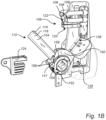
- the contact lever 104 is configured to rotate, that is, it is rotatable about the pivot point 114 between the closed position shown in fig. 1A , an open position shown in fig. 1B , and an earth position shown in fig. 1C where the contact lever 104 is in contact with an earthed contact 124.
- the electric current switch 100 further comprises a compressed gas device 126 having a movable piston 128 in a volume 130 housing gas compressible by the piston 128.
- the compressed gas being ejected from the nozzles 108 towards the fixed contact assembly 106.
- the piston 128 is mechanically coupled to the contact lever 104 via a de-latching mechanism 132 configured to decouple the motion of the piston 128 from the contact lever 104 when the contact lever moves from the open position towards the earth position.
- the coupling between the contact lever 104 and the piston 128 is configured such that when the contact lever 104 moves from the closed position shown in fig. 1A towards the open position shown in fig. 1B , the piston 128 moves with the contact lever 104 in a synchronized way.
- the movement of the piston in the volume 130 causes the piston to compress the gas inside the volume.
- the compressed gas is forced through piping or tubes 134 to the nozzles 108 whereby the gas is ejected towards the fixed contact assembly 106, at the location of the contact lever if it were in the closed position.
- the nozzle can be made of many different kinds of polymer materials or even metal.
- the present invention provides several embodiments of a de-latching mechanism 132 that decouples the piston 128 motion from the motion of the contact lever 104 which allows the contact lever 104 to reach the earth position shown in fig. 1C .
- the contact lever 104 connects with the earth or ground contact 124, schematically depicted in the drawings.
- the fixed main contact 120 and the earth contact 124 are stationary with respect to the pivot point 114 when the contact lever 104 moves between the earthed position, the closed position, and the open position.
- the contact lever 104 and the piston are the main moving parts of the electric current switch 100.
- the present disclosure presents several embodiments of a de-latching mechanism.
- the de-latching mechanism is arranged to in one state, couple the motion of the contact lever to the piston of the compressed gas device so that the move together.
- one component fixed to the contact lever abuts against a component coupled to the piston.
- the mechanical and physical contact between the component of the contact lever and the component coupled to the piston causes the contact lever to push or pull the piston along with its motion.
- the contact lever has rotated about its pivot point 114 or axis through a predetermined angle relative the orientation of the contact lever in the closed potion, the mechanical and physical contact between the component of the contact lever and the component coupled to the piston is relieved or lost. Thereby, the motion of the contact lever is de-coupled from the motion of the piston.
- the de-latching mechanism is configured to recouple the motion of the piston and the contact lever when the contact lever moves from the open position towards the closed position.
- the electric current switch is in a closed position in fig. 1A , in an open position in fig. 1B , and in the earthed position in fig. 1C .
- the de-latching mechanism comprises an arm 137 that is pivotably attached to the contact lever 104 on a first side 104a.
- a second arm 138 is pivotably attached at the same rotation axis as the first arm 137.
- the arms 137 and 138 are spring-loaded by a spring 140 which is mechanically coupled to the first arm 137 and the second arm 138 via a cross-bar or axle 142 attached to each of the arms 137, 138 at one end portion of the respective arms 137, 138.
- the axle 142, and the two arms 137 and 138 form an H-shape or horseshoe shape that wraps partly around the contact lever 104.
- the two spring-loaded arms 137 and 138 are arranged in parallel on opposite sides of the contact lever 104.
- the spring 140 biases the arms 137 and 138 towards the distal end 112 of the contact lever 104.
- the spring 142 may be connected between the axle 142 and a base of the contact lever 104.
- the spring-loaded arms 137 and 138 have similar features.
- the spring-loaded arms 137, 138 comprise a contact surface 144 configured to be engaged with a receiving surface 146 of a lock element 148 coupled with the puffer piston 128.
- a lock element 148 rotates about the pivot axis 114, it pulls or pushes the puffer piston 128 along with it through a linkage 150.
- the lock element 148 comprises a step or protrusions on which the receiving surface 146 is located.
- the spring 140 is arranged to pull the arms 137, 138 towards the lock element 148 so that contact surfaces 144 of the arms 137, 138 lie along the same trajectory which means that, when the contact lever 104 is rotated towards the open position, the contact surface 144 abuts against the receiving surface 146 of the lock element 148.
- a rotation of the contact lever 104 from the closed position in fig. 1A towards the open position in fig. 1B causes the contact surface 144 to push on the receiving surface 146 whereby the puffer piston 128 moves in the volume 130.
- a de-latching member 152 comprises a step 154 arranged so that the step 154 engages with a rolling member 156 attached to the spring-loaded arm 137, 138 to cause a pivoting motion of the spring-loaded arm 137, 138 about its pivot point 141.
- the pivoting motion causes the contact surface 144 to disengage from the receiving surface 146.
- the rolling members are disc-shaped or wheel-shaped so that they roll on a curved portion 158 of the de-latching member 152.
- Each of the spring-loaded arms 137, 138 have a respective rolling member 152 arranged at a common rotation axis defined by the axle 142 mechanically connected to the spring-loaded arms at the common rotation axis.
- the rolling members 152 are pushed towards the curved surface 158 along which the rolling members travel when the contact lever 104 rotates from the closed state towards the open state shown in fig. 1B .
- the wheels 156 climb on a respective step 154 of the de-latching members 152, one for each wheel 156.
- the step 154 may comprise an inclination 159 (see fig. 1A ) facing towards the curved surface 158 along which the wheel 156 approaches the step 154.
- the spring is extended, and the spring force increases.
- the contact surface 144 of the arm 137, 138 slides along the respective receiving surface 146 until they lose contact which decouples the contact lever 104 from the lock element 148. As shown in fig. 1C , this allows the contact lever 104 to rotate further without the lock element 148 and consequently also without the puffer piston 128 moving along with the contact lever 104.
- the contact lever 104 may then reach the earth contact 124.
- the arms 136, 138 move back to the original position so that they can again engage with the receiving surface 146 during the next current interruption event.
- the wheel 156 may be replaced by a fixed part which slides on the curved surface 158 and the step 154.
- Fig. 2A-B illustrates another embodiment according to the present disclosure.
- the de-latching mechanism comprises a hook 202 on one end 204a of a pivotable arm 204 attached to the contact lever 104.
- the pivotable arm 204 comprises a contact surface 206 on the hook 202 which engages with the receiving surface 208 of the lock element 210.
- the rotation of the lock element 210 is coupled to the motion of the puffer piston 128 in the volume 130.
- the pivotable arm 204 is rotatable about its rotation axis 212 where it is attached to the contact lever 104.
- the hook 202 is on end 204a of the arm 204 and on the other end 204b opposite the pivot axis 212 is a wheel or disc 216 attached to the pivot arm 204.
- the pivotable arm 204 is spring loaded to push the hook away 202 from the pivot point 114 of the contact lever 104 and the wheel 216 towards a contact surface 218 which is generally curved.
- the contact surface 218 comprises a first portion 218a and a second portion 218b separated by an inclined step 220.
- step 220 causes the wheel 216 to be pushed away from the pivot point 114 of the contact lever 104. This causes the hook 202 to move towards the pivot point 114 of the contact lever 104 so that the hook 202 is disengaged from the receiving surface 208.
- the spring pulls the wheel 216 closer to the pivot point 114 of the contact lever 104 compared to when the wheel has climbed the step 220. Since the hook is on the opposite side of the pivot axis 212 of the arm 204, the hook moves in the opposite direction compared to the wheel 216.
- the hook 202 In the closed state, the hook 202 is engaged in a pocket or shoulder 222 of the lock element 210 where the contact surface 208 is located.
- the hook moves 202 due to a rotation of the contact lever 104, it pushes the lock element 210 along with it which causes the puffer piston 128 to move in the volume 130, until the wheel 216 interacts with the step and the hook 202 is disengaged from the shoulder 222.
- the hook 202 moves back to the original position so that it can again engage with the receiving surface 208.
- Figs. 3A-C illustrates an electric switch 300 according to a third embodiment.
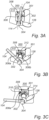
- the electric switch 300 is in a closed state
- in fig. 3B the electric switch is in an open state
- an in fig. 3C the electric switch is in the earthed state, although the earth contact and the fixed contact assembly have been omitted in figs. 3A-3C .
- the de-latching mechanism 301 comprises a spring-loaded hook 302 attached to a rotatable shaft 304.
- the rotatable shaft 304 rotates about axis 114 to move the contact lever 304 between its positions.
- the spring that loads the hook 302 biases the hook 302 away from the axis 114 and the shaft 304 and towards a contact surface 306 of flange 308 that is attached to a wall 310 of a housing for the switch 300.
- the contact surface 306 comprises a first portion 306a and a second portion 306b separated by a step 312.
- the first surface portion 306a is closer to the shaft 304 and its rotation axis 114 than the second surface portion 306b.
- the puffer piston 128 is connected to a receiving surface 314 formed in a cavity or hole or on one side of a bar onto which the hook 302 is engaged at least when the contact lever 104 is in the closed position and moves towards the open position. As long as the hook 302 is engaged with the receiving surface 314, the rotation of the contact lever also moves the puffer piston as illustrated by the displacement of the contact lever 104 and the puffer piston from the position in fig. 3A to the position in fig. 3B .
- the hook 302 engages in the cavity or hole or on one side of a bar where the receding surface is to move the puffer piston back to the start position in fig. 3A .
- Figs. 4A-C illustrates yet another embodiment of the present disclosure.
- the de-latching mechanism 402 comprises a pinching element 404 attached to the contact lever 104.
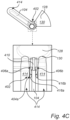
- the pinching element comprises two spring loaded legs 404a, 404b attached to opposite sides of the contact lever 104 meaning on opposite sides of the rotation plane of the contact lever 104.
- An actuation side 416a, 416b of the legs 404a, 404b opposite the engaging side 406a, 406b of the legs 404a, 404b interacts with the parallel dielectric shields 414 such that the actuation sides 416a, 416b of the legs 404a, 404b are pushed towards each other, see figs. 4B-C , they cause the engaging sides 406a, 406b to move away from each other and release the puffer piston element 410.
- the piston 128 is preferably pivotably attached about the same pivot axis 114 as the contact lever 104.
- the de-latching mechanism comprises an intermittent gear mechanism 502.
- a first gear 504 is attached to the contact lever 104 to rotate about the pivot point 114 and a second gear 506 is attached the piston 128 to rotate when the piston moves in the puffer volume 130.
- the amount of teeth on at least one of the gears 504, 506 corresponding to that the rotational coupling between the gears being interrupted when the contact lever 104 reaches the open position.
- nozzle and arcing contacts of the fixed contact assembly and the contact lever described herein may be dimensioned and shaped in various ways and are not limited to the specific configuration shown in the drawings.
- the nozzle 108 may be made from a suitable material appropriate for medium voltage applications.
- Example materials include Polytetrafluoroethylene (PTFE), Perfluoroalkoxy alkane (PFA), and Fluorinated ethylene propylene (FEP)
- Further example materials for the nozzle include Carbon-Hydrogen- polymers like PP, POM, PA, PMMA etc.
Landscapes
- Circuit Breakers (AREA)
Abstract
The present invention relates to an electric current switch comprising a compressed gas device (126) having a movable piston (128) in a volume (130) housing gas compressible by the piston, the compressed gas being ejected from a nozzle (108) towards a fixed contact assembly, the piston is mechanically coupled to the contact lever via a de-latching mechanism (132; 301; 402; 502) configured to decouple the motion of the piston from the contact lever when the contact lever moves from the open position towards the earth position.
Description
- The present invention relates to an electric current switch.
- Electric switches for medium- and high voltage switchgear are subject to electric arcing during current interruption and contact making events. Suppressing the arcs is important to protect the electric switch itself and electric devices connected to the electric switch.
- Effects of arcs may be suppressed by appropriate material selection of arcing contact areas of the connecting parts of the electric switch that can withstand and reduce the arcing. Further, arc-extinction can be provided by application of an appropriate gas onto the arc using a so-called puffer.
- A puffer often includes a piston that moves in a puffer volume for building up a gas pressure for subsequent ejection onto the arc region. The movement of the piston is coupled to the movement of one of the connecting parts of the switch so that the arc-extinction can be synchronized with the interruption of the electric current, i.e., when the switch is in an open position.
- However, it is desirable to also allow for the moving electric connecting part of the switch to also reach a third position beyond the open position, while still allowing efficient arc-extinction.
- In view of the above-mentioned and other drawbacks of the prior art, it is an object of the present invention to provide an electric current switch that at least partly alleviates the deficiencies with prior art.
- According to a first aspect of the invention, there is provided an electric current switch comprising: a housing; a contact lever comprising a proximal end and a distal end, the contact lever is rotatable at a pivot point at the distal end, the contact lever comprising a lever main contact area and a lever arcing contact at the proximal end; a fixed contact assembly configured to receive the contact lever in a closed position of the contact lever, the fixed contact assembly comprising a fixed main contact and a fixed arcing contact, the fixed contact assembly being fixed relative the housing accommodating the fixed contact; the contact lever is configured to rotate about the pivot point between the closed position, an open position, and an earth position where the contact lever is in contact with an earthed contact, the electric current switch further comprising a compressed gas device having a movable piston in a volume housing gas compressible by the piston, the compressed gas being ejected from a nozzle towards the fixed contact assembly, the piston is mechanically coupled to the contact lever via a de-latching mechanism configured to decouple the motion of the piston from the contact lever when the contact lever moves from the open position towards the earth position.
- The present invention is at least partly based on the realization that a de-latching mechanism allows the contact lever to decouple from the motion of the puffer piston once the contact lever has reached the open position or at least away from the closed position. In this way, the contact lever can rotate freely towards the earthed position where it contacts an earthed contact element.
- Furthermore, decoupling the contact lever from the puffer piston allows for designing the puffer volume so that a large, or even maximum gas pressure can be achieved at the right time, that is, at the moment of current interruption. Thus, the puffer can be designed so that the puffer piston has reached to or at least near the bottom of the puffer volume during the electric current interruption phase. If the puffer piston is not decoupled from the contact lever at this time, the contact lever would not be allowed to move further to the earthed position.
- The de-latching mechanism may be configured in various ways as will be laid out herein. However, the de-latching mechanism includes a mechanism which locks the motion of the puffer piston to contact lever when it moves from the closed position towards the open position. Once the contact lever has rotated through a given rotation angle corresponding to the motion from the closed position to the open position, the locked motion is released and the contact lever moves without causing the puffer piston to move further in the puffer volume.
- It is often the case that the de-latching mechanism includes a locking interface comprising at least one surface that rotates with the contact lever and that is engaged or in contact with a surface coupled to the puffer piston. The connection or engagement between the surfaces is such that when the contact lever rotates it causes the puffer piston to also move inside the puffer volume. However, after a predetermined rotation angle of the contact lever, the connection or engagement between the surface that rotates with the contact lever and the surface coupled to the puffer piston is released or interrupted, whereby the puffer piston is no longer caused to move when the contact elver rotates about its pivot point.
- The housing provides an assembly base for the electric switch. The pivot point is preferably fixed in relation to the housing.
- In the closed position of the contact lever, an electric current may pass between the lever main contact area and the fixed main contact. In the open position, the contact lever and the fixed contact are not in contact whereby an electric current may not pass between them.
- In the closed position, the lever main contact area mate with the fixed main contact.
- The gas may for example comprise at least one background gas component selected from the group consisting of CO2, O2, N2, H2, air, N2O, in a mixture with a hydrocarbon or an organo fluorine compound. For example, the cooling gas may comprise dry air or technical air. The cooling gas may in particular comprise an organofluorine compound selected from the group comprising of: a fluoroether, an oxirane, a fluoramine, a fluoroketone, a fluoroolefin, a fluoronitrile, and mixtures and/or decomposition products thereof. In particular, the cooling gas may comprise as a hydrocarbon at least CH4, a perfluorinated and/or partially hydrogenated organofluorine compound, and mixtures thereof. The organofluorine compound is preferably selected from the group comprising of: a fluorocarbon, a fluoroether, a fluoroamine, a fluoronitrile, and a fluoroketone; and preferably is a fluoroketone and/or a fluoroether, more preferably a perfluoroketone and/or a hydro fluoroether, more preferably a perfluoroketone having from 4 to 12 carbon atoms and even more preferably a perfluoroketone having 4, 5 or 6 carbon atoms. In particular, the perfluoroketone is or comprises at least one of: C2F5C(O)CF(CF3)2 or dodecafiuoro-2-methylpentan-3-one, and CF3C(O)CF(CF3)2 or decafluoro-3-methylbutan-2-one. The cooling gas preferably may comprise the fluoroketone mixed with air or an air component such as N2, O2, and/or CO2. Another possible cooling gas is SF6. The cooling gas may comprise air or an air component such as N2, O2, and/or CO2 without the fluoroketone.
- A nozzle may be fixedly attached to the fixed contact assembly to ensure that the cooling gas is provided towards an arc root. Further, with the nozzle attached to the fixed contact assembly, a more compact electric switch is provided compared to having the nozzle be arranged separately from the fixed contact assembly.
- The earth contact may be fixed in relation to the housing. Thus, the contact lever is rotatable to three positions, while the earth contact, the fixed contact, and the nozzle are fixed in relation to the housing.
- The fixed contact and the earth contact may be stationary with respect to the pivot point when the contact lever moves between the earthed position, the closed position, and the open position.
- Preferably, the de-latching mechanism is configured to decouple the motion of the piston from the contact lever at a predetermined rotation angle of the contact lever around its pivot point. The predetermined rotation angle corresponds to the rotation angle required to rotate the contact lever from the closed position to the open position.
- In embodiments, the de-latching mechanism may advantageously comprise: a spring-loaded arm pivotably attached to the contact lever, the spring loaded arm comprising a contact surface configured to be engaged with a receiving surface of a lock element coupled with the puffer piston, wherein a rotation of the contact lever from the closed position towards the open position causes the contact surface to push on the receiving surface whereby the puffer piston moves in the volume, a de-latching member comprising a step arranged so that the step engages with a rolling member attached to the spring-loaded arm to cause a pivoting motion of the spring-loaded arm about its pivot point, wherein the pivoting motion causes the contact surface to disengage from the receiving surface. This provides one robust yet relatively simple de-latching mechanism that only relies on mechanical moving parts.
- In one embodiment, the de-latching mechanism may comprise two spring-loaded arms arranged in parallel on opposite sides of the contact lever, each of the spring-loaded arms having a respective rolling member arranged at a common rotation axis, and an axle mechanically connected to the spring-loaded arms at the common rotation axis, and a spring connected between the axle and a base of the contact lever, the spring biasing the spring-loaded arms so that the rolling members are pushed towards the de-latching member. Parallelly arranged spring-loaded arms provide for better mechanical stability of de-latching mechanism and also stronger locking in the engaged position between the contact lever and the puffer piston.
- In another embodiment, the de-latching mechanism may comprise a hook on one end of a pivotable arm attached to the contact lever, and a disc element attached to the other end of the pivotable arm, the pivot point of the pivotable arm is located between the hook and the wheel, and the pivotable arm is spring loaded to push the hook away from the pivot point of the contact lever and the wheel towards a contact surface comprising a first portion and a second portion separated by a step, wherein, the puffer piston is coupled with a receiving surface which the hook is engaged with at least when the contact lever is in the closed position and moves towards the open position. This provides another one robust yet relatively simple de-latching mechanism that only relies on mechanical moving parts.
- In one embodiment, when the contact lever is rotated about its pivot point, the disc element may travel along the contact surface, and by interaction with the step, the wheel is pushed away from the pivot point of the contact lever whereby the hook is moved towards the pivot point of the contact lever so that the hook is disengaged from the receiving surface. Interaction with the step conveniently arranged at the right rotation angle of the contact lever provides for reliable synchronization of the decoupling between the contact lever and the puffer piston.
- In another embodiment, the de-latching mechanism may comprise: a spring-loaded hook attached to a rotatable shaft aligned with the pivot point of the contact lever, the spring is configured to push the hook away from the shaft, and a disc attached to the hook and being pushed by the spring towards a contact surface further away from the shaft, the contact surface comprising a first portion and a second portion separated by a step, the puffer piston is coupled to a receiving surface which the hook is engaged with at least when the contact lever is in the closed position and moves towards the open position. This provides another one robust yet relatively simple de-latching mechanism that only relies on mechanical moving parts.
- Preferably a single spring-loaded hook is used thereby reducing the risk of mechanical failure.
- In one embodiment, the contact surface is comprised in a flange attached to a wall of the housing. Accordingly, the de-latching mechanism is located a distance away from the contact lever which means its more easily accessible for e.g., maintenance purposes.
- In one embodiment, when the contact lever is rotated about its pivot point, the wheel may travel along the contact surface, and by interaction with the step, the wheel and hook are pushed away from the shaft of the contact lever so that the hook is disengaged from the receiving surface of the puffer piston.
- In another embodiment, the de-latching mechanism may comprise a pinching element attached to the contact lever that pinches to an element connected to the puffer piston, the pinching element comprising two legs each with an engaging side configured to pinch the puffer piston element and each with an actuation side, configured such that which when the actuation sides of the legs are pushed towards each other they cause the engaging sides to move away from each other and release the puffer piston element. This provides another one robust yet relatively simple de-latching mechanism that only relies on mechanical moving parts.
- In embodiments, the piston may be pivotably attached about the same pivot axis as the contact lever.
- In another embodiment, the de-latching mechanism may comprise an intermittent gear mechanism, where a first gear is attached to the contact lever to rotate about the pivot point and a second gear is attached the piston to rotate when the piston moves in the puffer volume, the amount of teeth on at least one of the gears corresponding to that the rotational coupling between the gears being interrupted when the contact lever reaches the open position. This provides another one robust yet relatively simple de-latching mechanism that only relies on mechanical moving parts.
- In embodiments, the de-latching mechanism is configured to recouple the motion of the piston and the contact lever when the contact lever moves from the open position towards the closed position. This advantageously allows for continued operation of the de-latching mechanism during the next electric current interruption.
- In embodiments, the contact lever may be a knife contact, and the electric current switch may be a knife switch.
- Further features of, and advantages with, the present invention will become apparent when studying the appended claims and the following description. The skilled person realizes that different features of the present invention may be combined to create embodiments other than those described in the following, without departing from the scope of the present invention.
- These and other aspects of the present invention will now be described in more detail, with reference to the appended drawings showing an example embodiment of the invention, wherein:
-
Fig. 1A illustrates an example electric current switch in one position according to embodiments of the invention; -
Fig. 1B illustrates the example electric current switch infig 1A in another one position according to embodiments of the invention; -
Fig. 1C illustrates the example electric current switch infig 1A in another one position according to embodiments of the invention; -
Fig. 2A illustrates an example electric current switch in one position according to embodiments of the invention; -
Fig. 2B illustrates the latching mechanism of the example electric current switch infig 2A in another one position according to embodiments of the invention; -
Fig. 3A illustrates an example electric current switch in one position according to embodiments of the invention; -
Fig. 3B illustrates the example electric current switch infig. 3A in another one position according to embodiments of the invention; -
Fig. 3C illustrates the example electric current switch infig. 3A in another one position according to embodiments of the invention; -
Fig. 4A illustrates an example electric current switch in one position according to embodiments of the invention; -
Fig. 4B illustrates the example electric current switch infig. 4A in another one position according to embodiments of the invention; -
Fig. 4C illustrates the example electric current switch infig. 4A in another one position according to embodiments of the invention; -
Fig. 5A illustrates an example electric current switch in one position according to embodiments of the invention; and -
Fig. 5B illustrates the example electric current switch infig. 5A in another one position according to embodiments of the invention. - In the present detailed description, various embodiments of the present invention are herein described with reference to specific implementations. In describing embodiments, specific terminology is employed for the sake of clarity. However, the invention is not intended to be limited to the specific terminology so selected. While specific exemplary embodiments are discussed, it should be understood that this is done for illustration purposes only. A person skilled in the relevant art will recognize that other components and configurations can be used without parting from the scope of the invention.
-
Fig. 1A illustrates an example electriccurrent switch 100 in a closed position. The electric current switch 100 a knife switch often also referred to as a blade switch. - The electric
current switch 100 comprises ahousing 102 that accommodates acontact lever 104, a fixedcontact assembly 106 and a set ofnozzles 108 or which one is numbered. - The
contact lever 104, sometimes referred to as a knife contact or blade contact, comprises aproximal end 110 and adistal end 112. Thecontact lever 104 is rotatable at apivot point 114 at or near or at least closer to thedistal end 112 than to theproximal end 110. As better seen infig. 1B , thecontact lever 104 comprises a lever main contact area 116 and alever arcing contact 118 at theproximal end 110. - The fixed
contact assembly 106 is configured to receive thecontact lever 104 in a closed position of the contact lever. The closed position is shown infig. 1A . The fixedcontact assembly 106 comprises a fixedmain contact 120 and a fixedarcing contact 122 where the fixedcontact assembly 106 is fixed relative thehousing 102 accommodating thefixed contact 106. - The
contact lever 104 is configured to rotate, that is, it is rotatable about thepivot point 114 between the closed position shown infig. 1A , an open position shown infig. 1B , and an earth position shown infig. 1C where thecontact lever 104 is in contact with anearthed contact 124. - The electric
current switch 100 further comprises acompressed gas device 126 having amovable piston 128 in avolume 130 housing gas compressible by thepiston 128. - The compressed gas being ejected from the
nozzles 108 towards the fixedcontact assembly 106. Thepiston 128 is mechanically coupled to thecontact lever 104 via ade-latching mechanism 132 configured to decouple the motion of thepiston 128 from thecontact lever 104 when the contact lever moves from the open position towards the earth position. - The coupling between the
contact lever 104 and thepiston 128 is configured such that when thecontact lever 104 moves from the closed position shown infig. 1A towards the open position shown infig. 1B , thepiston 128 moves with thecontact lever 104 in a synchronized way. The movement of the piston in thevolume 130 causes the piston to compress the gas inside the volume. The compressed gas is forced through piping ortubes 134 to thenozzles 108 whereby the gas is ejected towards the fixedcontact assembly 106, at the location of the contact lever if it were in the closed position. - As the
contact lever 104 moves from the closed position where it is in electrical and mechanical contact with themain contact 120, an arc often appears between thecontact lever 104 and thearc contact 122. This arc is extinct by the gas pressurized by thepiston 128 and ejected by thenozzles 108. The nozzle can be made of many different kinds of polymer materials or even metal. - Once the
contact lever 104 reaches the open position shown infig. 1B , the arc is already extinct, and the piston motion has reached theend 136 of the volume. It is not desirable to increase thesize volume 130 because it would hamper the performance of thecompressed gas device 126 due to the reduction in pressure. Instead, the present invention provides several embodiments of ade-latching mechanism 132 that decouples thepiston 128 motion from the motion of thecontact lever 104 which allows thecontact lever 104 to reach the earth position shown infig. 1C . In the earthed position, thecontact lever 104 connects with the earth orground contact 124, schematically depicted in the drawings. - The fixed
main contact 120 and theearth contact 124 are stationary with respect to thepivot point 114 when thecontact lever 104 moves between the earthed position, the closed position, and the open position. Generally, thecontact lever 104 and the piston are the main moving parts of the electriccurrent switch 100. - The present disclosure presents several embodiments of a de-latching mechanism. The de-latching mechanism is arranged to in one state, couple the motion of the contact lever to the piston of the compressed gas device so that the move together. In this first state, one component fixed to the contact lever abuts against a component coupled to the piston. The mechanical and physical contact between the component of the contact lever and the component coupled to the piston causes the contact lever to push or pull the piston along with its motion. As the contact lever has rotated about its
pivot point 114 or axis through a predetermined angle relative the orientation of the contact lever in the closed potion, the mechanical and physical contact between the component of the contact lever and the component coupled to the piston is relieved or lost. Thereby, the motion of the contact lever is de-coupled from the motion of the piston. - Generally, for embodiments herein, the de-latching mechanism is configured to recouple the motion of the piston and the contact lever when the contact lever moves from the open position towards the closed position.
- In one embodiment illustrated in
figs. 1A-1C , the electric current switch is in a closed position infig. 1A , in an open position infig. 1B , and in the earthed position infig. 1C . - Turning again to
fig. 1A , the de-latching mechanism comprises anarm 137 that is pivotably attached to thecontact lever 104 on afirst side 104a. On the second side, opposite thefirst side 104a, asecond arm 138 is pivotably attached at the same rotation axis as thefirst arm 137. Thearms spring 140 which is mechanically coupled to thefirst arm 137 and thesecond arm 138 via a cross-bar oraxle 142 attached to each of thearms respective arms axle 142, and the twoarms contact lever 104. Thus, the two spring-loadedarms contact lever 104. Thespring 140 biases thearms distal end 112 of thecontact lever 104. Thespring 142 may be connected between theaxle 142 and a base of thecontact lever 104. - The spring-loaded
arms - The spring-loaded
arms contact surface 144 configured to be engaged with a receivingsurface 146 of alock element 148 coupled with thepuffer piston 128. When thelock element 148 rotates about thepivot axis 114, it pulls or pushes thepuffer piston 128 along with it through alinkage 150. - The
lock element 148 comprises a step or protrusions on which the receivingsurface 146 is located. Thespring 140 is arranged to pull thearms lock element 148 so that contact surfaces 144 of thearms contact lever 104 is rotated towards the open position, thecontact surface 144 abuts against the receivingsurface 146 of thelock element 148. In other words, a rotation of thecontact lever 104 from the closed position infig. 1A towards the open position infig. 1B causes thecontact surface 144 to push on the receivingsurface 146 whereby thepuffer piston 128 moves in thevolume 130. - Furthermore, a
de-latching member 152 comprises astep 154 arranged so that thestep 154 engages with a rollingmember 156 attached to the spring-loadedarm arm pivot point 141. The pivoting motion causes thecontact surface 144 to disengage from the receivingsurface 146. The rolling members are disc-shaped or wheel-shaped so that they roll on acurved portion 158 of thede-latching member 152. Each of the spring-loadedarms member 152 arranged at a common rotation axis defined by theaxle 142 mechanically connected to the spring-loaded arms at the common rotation axis. Thespring 140 between theaxle 142 and the base of thecontact lever 104 biases the spring-loadedarms members 156 are pushed towards the de-latching member. In the closed state of theswitch 100, the rollingmembers 152 are pushed towards thecurved surface 158 along which the rolling members travel when thecontact lever 104 rotates from the closed state towards the open state shown infig. 1B . - When the
contact lever 104 is rotated and the lock-element 148 is pushed on by thearm 137, thelock element 148 rotates with respect to thede-latching member 152. In other words, thede-latching member 152 is fixated with respect to thelock element 148, both of which have a general circular shape. - As shown in
fig. 1B , in the open position of theswitch 100, when thecontact lever 104 has rotated through a predetermined rotation angle, thewheels 156 climb on arespective step 154 of thede-latching members 152, one for eachwheel 156. Thestep 154 may comprise an inclination 159 (seefig. 1A ) facing towards thecurved surface 158 along which thewheel 156 approaches thestep 154. When thewheels 156 climb therespective step 154, the spring is extended, and the spring force increases. Furthermore, thecontact surface 144 of thearm respective receiving surface 146 until they lose contact which decouples thecontact lever 104 from thelock element 148. As shown infig. 1C , this allows thecontact lever 104 to rotate further without thelock element 148 and consequently also without thepuffer piston 128 moving along with thecontact lever 104. Thecontact lever 104 may then reach theearth contact 124. - If the
contact lever 104 is rotated in the opposite direction back to the open position, thearms surface 146 during the next current interruption event. - The
wheel 156 may be replaced by a fixed part which slides on thecurved surface 158 and thestep 154. -
Fig. 2A-B illustrates another embodiment according to the present disclosure. In the electriccurrent switch 200, the de-latching mechanism comprises ahook 202 on oneend 204a of apivotable arm 204 attached to thecontact lever 104. Thepivotable arm 204 comprises acontact surface 206 on thehook 202 which engages with the receivingsurface 208 of thelock element 210. As above, the rotation of thelock element 210 is coupled to the motion of thepuffer piston 128 in thevolume 130. - The
pivotable arm 204 is rotatable about itsrotation axis 212 where it is attached to thecontact lever 104. Thehook 202 is onend 204a of thearm 204 and on theother end 204b opposite thepivot axis 212 is a wheel ordisc 216 attached to thepivot arm 204. - The
pivotable arm 204 is spring loaded to push the hook away 202 from thepivot point 114 of thecontact lever 104 and thewheel 216 towards acontact surface 218 which is generally curved. Thecontact surface 218 comprises afirst portion 218a and asecond portion 218b separated by aninclined step 220. - When the
contact lever 104 rotates further from the position shown infig. 2A , thewheel 216 climbs thestep 220 which causes thepivotable arm 204 to rotate clock-wise infig. 2A to the position shown infig. 2B . - The interaction between the wheel as it travels along the
contact surface 218a and subsequently interacts withstep 220 causes thewheel 216 to be pushed away from thepivot point 114 of thecontact lever 104. This causes thehook 202 to move towards thepivot point 114 of thecontact lever 104 so that thehook 202 is disengaged from the receivingsurface 208. - In other words, in the initial closed state of the electric
current switch 200, the spring pulls thewheel 216 closer to thepivot point 114 of thecontact lever 104 compared to when the wheel has climbed thestep 220. Since the hook is on the opposite side of thepivot axis 212 of thearm 204, the hook moves in the opposite direction compared to thewheel 216. - In the closed state, the
hook 202 is engaged in a pocket orshoulder 222 of thelock element 210 where thecontact surface 208 is located. When the hook moves 202 due to a rotation of thecontact lever 104, it pushes thelock element 210 along with it which causes thepuffer piston 128 to move in thevolume 130, until thewheel 216 interacts with the step and thehook 202 is disengaged from theshoulder 222. - If the
contact lever 104 rotated in the opposite direction back to the open position, thehook 202 moves back to the original position so that it can again engage with the receivingsurface 208. -
Figs. 3A-C illustrates anelectric switch 300 according to a third embodiment. Infig 3A , theelectric switch 300 is in a closed state, infig. 3B , the electric switch is in an open state, an infig. 3C the electric switch is in the earthed state, although the earth contact and the fixed contact assembly have been omitted infigs. 3A-3C . - The
de-latching mechanism 301 comprises a spring-loadedhook 302 attached to arotatable shaft 304. Therotatable shaft 304 rotates aboutaxis 114 to move thecontact lever 304 between its positions. The spring that loads thehook 302 biases thehook 302 away from theaxis 114 and theshaft 304 and towards acontact surface 306 offlange 308 that is attached to awall 310 of a housing for theswitch 300. - The
contact surface 306 comprises afirst portion 306a and asecond portion 306b separated by astep 312. Thefirst surface portion 306a is closer to theshaft 304 and itsrotation axis 114 than thesecond surface portion 306b. - The
puffer piston 128 is connected to a receivingsurface 314 formed in a cavity or hole or on one side of a bar onto which thehook 302 is engaged at least when thecontact lever 104 is in the closed position and moves towards the open position. As long as thehook 302 is engaged with the receivingsurface 314, the rotation of the contact lever also moves the puffer piston as illustrated by the displacement of thecontact lever 104 and the puffer piston from the position infig. 3A to the position infig. 3B . - However, as best seen in
fig. 3B , as thehook 302 slides or rolls with itswheel 318 through thestep 312, the spring pushes thehook 302 away from theaxis 114 so that thehook 302 disengages from the receivingsurface 314. Consequently, thecontact lever 104 motion is de-coupled from the puffer piston motion. In other words, when thecontact lever 104 is rotated about itspivot point 114, thewheel 318 travels along thecontact surface 306, and by interaction with thestep 312, thewheel 318 and hook 302 are pushed away from theshaft 304 of the contact lever so that the hook is disengaged from the receiving surface of the puffer piston. - If the contact lever is moved from the earthed position in
fig. 3C and back so that thehook 302 travels through the step again, thehook 302 engages in the cavity or hole or on one side of a bar where the receding surface is to move the puffer piston back to the start position infig. 3A . -
Figs. 4A-C illustrates yet another embodiment of the present disclosure. In this embodiment, thede-latching mechanism 402 comprises a pinchingelement 404 attached to thecontact lever 104. The pinching element comprises two spring loadedlegs contact lever 104 meaning on opposite sides of the rotation plane of thecontact lever 104. - An
engaging side legs puffer piston element 410 connected to thepuffer piston 128. As thecontact lever 104 moves towards the open position shown infig. 4B from the initial closed position shown infig. 4A , the pinching element with itslegs puffer piston element 410 so that thepuffer piston 128 moves synchronously with the contact lever. At a predetermined rotation angle, thecontact lever 104 reaches paralleldielectric shields 414 which thecontact lever 104 moves in-between. Anactuation side legs engaging side legs dielectric shields 414 such that theactuation sides legs figs. 4B-C , they cause the engagingsides puffer piston element 410. - As the
contact lever 104 is rotated back towards the closed position the pinchingelement 404 again pinches onto thepuffer piston element 410. - In the above embodiments, the
piston 128 is preferably pivotably attached about thesame pivot axis 114 as thecontact lever 104. - Now turning to
figs. 5A-B illustrating yet another embodiment. Here, the de-latching mechanism comprises anintermittent gear mechanism 502. Afirst gear 504 is attached to thecontact lever 104 to rotate about thepivot point 114 and asecond gear 506 is attached thepiston 128 to rotate when the piston moves in thepuffer volume 130. The amount of teeth on at least one of thegears contact lever 104 reaches the open position. - The nozzle and arcing contacts of the fixed contact assembly and the contact lever described herein may be dimensioned and shaped in various ways and are not limited to the specific configuration shown in the drawings.
- Further, the
nozzle 108 may be made from a suitable material appropriate for medium voltage applications. Example materials include Polytetrafluoroethylene (PTFE), Perfluoroalkoxy alkane (PFA), and Fluorinated ethylene propylene (FEP) Further example materials for the nozzle include Carbon-Hydrogen- polymers like PP, POM, PA, PMMA etc. - Even though the invention has been described with reference to specific exemplifying embodiments thereof, many different alterations, modifications and the like will become apparent for those skilled in the art.
- Additionally, variations to the disclosed embodiments can be understood and effected by the skilled person in practicing the claimed invention, from a study of the drawings, the disclosure, and the appended claims. In the claims, the word "comprising" does not exclude other elements or steps, and the indefinite article "a" or "an" does not exclude a plurality. The mere fact that certain measures are recited in mutually different dependent claims does not indicate that a combination of these measures cannot be used to advantage.
Claims (15)
- An electric current switch (100;200;300;400) comprising:a housing (102);a contact lever (104) comprising a proximal end (110) and a distal end (112), the contact lever is rotatable at a pivot point (114) at the distal end, the contact lever comprising a lever main contact area (116) and a lever arcing contact (118) at the proximal end;a fixed contact assembly (106) configured to receive the contact lever in a closed position of the contact lever, the fixed contact assembly comprising a fixed main contact (120) and a fixed arcing contact (122), the fixed contact assembly being fixed relative the housing accommodating the fixed contact;the contact lever is configured to rotate about the pivot point between the closed position, an open position, and an earth position where the contact lever is in contact with an earthed contact (124),the electric current switch further comprising a compressed gas device (126) having a movable piston (128) in a volume (130) housing gas compressible by the piston, the compressed gas being ejected from a nozzle (108) towards the fixed contact assembly, the piston is mechanically coupled to the contact lever via a de-latching mechanism (132; 301; 402; 502) configured to decouple the motion of the piston from the contact lever when the contact lever moves from the open position towards the earth position.
- The electric current switch according to claim 1, wherein the de-latching mechanism is configured to decouple the motion of the piston from the contact lever at a predetermined rotation angle of the contact lever around its pivot point.
- The electric current switch according to any one of claims 1 and 2, wherein the de-latching mechanism comprises:a spring-loaded arm (136, 138) pivotably attached to the contact lever, the spring loaded arm comprising a contact surface (144) configured to be engaged with a receiving surface (146) of a lock element (148) coupled with the puffer piston, wherein a rotation of the contact lever from the closed position towards the open position causes the contact surface to push on the receiving surface whereby the puffer piston moves in the volume,a de-latching member (152) comprising a step (154) arranged so that the step engages with a rolling member (156) attached to the spring-loaded arm to cause a pivoting motion of the spring-loaded arm about its pivot point, wherein the pivoting motion causes the contact surface to disengage from the receiving surface.
- The electric current switch according to claim 3, wherein the de-latching mechanism comprises two spring-loaded arms arranged in parallel on opposite sides of the contact lever,each of the spring-loaded arms having a respective rolling member arranged at a common rotation axis, and an axle (142) mechanically connected to the spring-loaded arms at the common rotation axis, anda spring connected between the axle and a base of the contact lever, the spring biasing the spring-loaded arms so that the rolling members are pushed towards the de-latching member.
- The electric current switch according to any one of claims 1 and 2, wherein the de-latching mechanism comprises:a hook (202) on one end of a pivotable arm (204) attached to the contact lever, anda wheel (216) attached to the other end of the pivotable arm,the pivot point of the pivotable arm is located between the hook and the wheel, and the pivotable arm is spring loaded to push the hook away from the pivot point of the contact lever and the wheel towards a contact surface (218a) comprising a first portion (218a) and a second portion (218b) separated by a step (220), wherein,the puffer piston is coupled with a receiving surface (208) which the hook is engaged with at least when the contact lever is in the closed position and moves towards the open position.
- The electric current switch according to claim 5, wherein,
when the contact lever is rotated about its pivot point, the wheel travels along the contact surface, and by interaction with the step, the wheel is pushed away from the pivot point of the contact lever whereby the hook is moved towards the pivot point of the contact lever so that the hook is disengaged from the receiving surface. - The electric current switch according to any one of claims 1 and 2, wherein the de-latching mechanism comprises:a spring-loaded hook (302) attached to a rotatable shaft (304) aligned with the pivot point of the contact lever, the spring is configured to push the hook away from the shaft, anda wheel (218) attached to the hook and being pushed by the spring towards a contact surface (306) further away from the shaft, the contact surface comprising a first portion and a second portion separated by a step,the puffer piston is coupled to a receiving surface (314) which the hook is engaged with at least when the contact lever is in the closed position and moves towards the open position.
- The electric current switch according to claim 7, wherein the contact surface is comprised in a flange (308) attached to a wall of the housing.
- The electric current switch according to any one of claims 7 and 8, wherein,
when the contact lever is rotated about its pivot point, the wheel travels along the contact surface, and by interaction with the step, the wheel and hook are pushed away from the shaft of the contact lever so that the hook is disengaged from the receiving surface of the puffer piston. - The electric current switch according to any one of claims 1 and 2, comprising a pinching element (404) attached to the contact lever that pinches to an element (410) connected to the puffer piston, the pinching element comprising two spring loaded legs (404a, 404b) each with an engaging side (406a, 406b) configured to pinch the puffer piston element and each with an actuation side (408a, 408b), configured such that which when the actuation sides of the legs are pushed towards each other they cause the engaging sides to move away from each other and release the puffer piston element.
- The electric current switch according to any one of the preceding claims, wherein the piston is pivotably attached about the same pivot axis as the contact lever.
- The electric current switch according to any one of claims 1 and 2, wherein the de-latching mechanism comprises an intermittent gear mechanism (502), where a first gear (504) is attached to the contact lever to rotate about the pivot point and a second gear (506) is attached the piston to rotate when the piston moves in the puffer volume, the amount of teeth (508) on at least one of the gears corresponding to that the rotational coupling between the gears being interrupted when the contact lever reaches the open position.
- The electric current switch according to any one of the preceding claims, wherein the de-latching mechanism is configured to recouple the motion of the piston and the contact lever when the contact lever moves from the open position towards the closed position.
- The electric current switch according to any one of the preceding claims, wherein the fixed contact and the earth contact are stationary with respect to the pivot point when the contact lever moves between the earthed position, the closed position, and the open position.
- The electric current switch according to any one of the preceding claims, wherein the contact lever is a knife contact, and the electric current switch is a knife switch.
Priority Applications (2)
| Application Number | Priority Date | Filing Date | Title |
|---|---|---|---|
| EP23212315.8A EP4560676A1 (en) | 2023-11-27 | 2023-11-27 | An electric current knife switch comprising a puffer de-latching mechanism |
| PCT/EP2024/083222 WO2025114147A1 (en) | 2023-11-27 | 2024-11-22 | An electric current knife switch comprising a puffer de-latching mechanism |
Applications Claiming Priority (1)
| Application Number | Priority Date | Filing Date | Title |
|---|---|---|---|
| EP23212315.8A EP4560676A1 (en) | 2023-11-27 | 2023-11-27 | An electric current knife switch comprising a puffer de-latching mechanism |
Publications (1)
| Publication Number | Publication Date |
|---|---|
| EP4560676A1 true EP4560676A1 (en) | 2025-05-28 |
Family
ID=88975717
Family Applications (1)
| Application Number | Title | Priority Date | Filing Date |
|---|---|---|---|
| EP23212315.8A Withdrawn EP4560676A1 (en) | 2023-11-27 | 2023-11-27 | An electric current knife switch comprising a puffer de-latching mechanism |
Country Status (2)
| Country | Link |
|---|---|
| EP (1) | EP4560676A1 (en) |
| WO (1) | WO2025114147A1 (en) |
Citations (3)
| Publication number | Priority date | Publication date | Assignee | Title |
|---|---|---|---|---|
| US2399485A (en) * | 1942-12-26 | 1946-04-30 | Gen Electric | Electric circuit breaker |
| EP3916751B1 (en) * | 2020-05-27 | 2023-08-02 | Cooper Edison (Pingdingshan) Electronic Technologies Co., Ltd. | An arc extinguishing nozzle and a load switch with the arc extinguishing nozzle |
| US20230290593A1 (en) * | 2022-03-10 | 2023-09-14 | Abb Schweiz Ag | An electric current knife switch |
-
2023
- 2023-11-27 EP EP23212315.8A patent/EP4560676A1/en not_active Withdrawn
-
2024
- 2024-11-22 WO PCT/EP2024/083222 patent/WO2025114147A1/en active Pending
Patent Citations (3)
| Publication number | Priority date | Publication date | Assignee | Title |
|---|---|---|---|---|
| US2399485A (en) * | 1942-12-26 | 1946-04-30 | Gen Electric | Electric circuit breaker |
| EP3916751B1 (en) * | 2020-05-27 | 2023-08-02 | Cooper Edison (Pingdingshan) Electronic Technologies Co., Ltd. | An arc extinguishing nozzle and a load switch with the arc extinguishing nozzle |
| US20230290593A1 (en) * | 2022-03-10 | 2023-09-14 | Abb Schweiz Ag | An electric current knife switch |
Also Published As
| Publication number | Publication date |
|---|---|
| WO2025114147A1 (en) | 2025-06-05 |
Similar Documents
| Publication | Publication Date | Title |
|---|---|---|
| EP0679829A1 (en) | Coupling apparatus | |
| CN101990692B (en) | An actuator device and an electric switch device provided therewith | |
| JP7386523B2 (en) | connector lock mechanism | |
| US20110124213A1 (en) | Lever type electrical connector | |
| CA2409306A1 (en) | Retractable needle assembly | |
| EP0722204B1 (en) | Electrical connector having a mating slide with customized camming slot | |
| US12381054B2 (en) | Electric current knife switch | |
| US4503293A (en) | Interlocking plug and receptacle mechanism with actuating means | |
| WO2025114147A1 (en) | An electric current knife switch comprising a puffer de-latching mechanism | |
| EP3791416B1 (en) | Snap action switch for generating feedbacks | |
| US5449298A (en) | Latching system for intermatable connectors | |
| KR100301176B1 (en) | Self-adjusting plunger switch | |
| US3384861A (en) | Loadbread device | |
| US12311101B1 (en) | Trigger assembly for inhaler, and inhaler | |
| EP4664504A1 (en) | A compressed gas device for a multiphase rotary break switch | |
| CN116565743B (en) | Unlocking structure of drawer seat | |
| CN116838194B (en) | Push type telescopic pushing device and storage equipment | |
| CN217908250U (en) | Cantilever storage device and medical trolley | |
| EP4407646A1 (en) | An electric current knife switch | |
| CN214012811U (en) | Operating mechanism and isolating switch | |
| CN1096697C (en) | Switch device | |
| CN223825374U (en) | Buckle structure | |
| US12472315B1 (en) | Trigger assembly for inhaler, and inhaler | |
| JPS645791Y2 (en) | ||
| KR102884532B1 (en) | Plug arrangement |
Legal Events
| Date | Code | Title | Description |
|---|---|---|---|
| PUAI | Public reference made under article 153(3) epc to a published international application that has entered the european phase |
Free format text: ORIGINAL CODE: 0009012 |
|
| STAA | Information on the status of an ep patent application or granted ep patent |
Free format text: STATUS: THE APPLICATION HAS BEEN PUBLISHED |
|
| AK | Designated contracting states |
Kind code of ref document: A1 Designated state(s): AL AT BE BG CH CY CZ DE DK EE ES FI FR GB GR HR HU IE IS IT LI LT LU LV MC ME MK MT NL NO PL PT RO RS SE SI SK SM TR |
|
| STAA | Information on the status of an ep patent application or granted ep patent |
Free format text: STATUS: THE APPLICATION IS DEEMED TO BE WITHDRAWN |
|
| 18D | Application deemed to be withdrawn |
Effective date: 20251129 |