EP4560603A1 - Map generating device and driving assistance system - Google Patents
Map generating device and driving assistance system Download PDFInfo
- Publication number
- EP4560603A1 EP4560603A1 EP22952022.6A EP22952022A EP4560603A1 EP 4560603 A1 EP4560603 A1 EP 4560603A1 EP 22952022 A EP22952022 A EP 22952022A EP 4560603 A1 EP4560603 A1 EP 4560603A1
- Authority
- EP
- European Patent Office
- Prior art keywords
- information
- map
- monitoring
- hazardous area
- mover
- Prior art date
- Legal status (The legal status is an assumption and is not a legal conclusion. Google has not performed a legal analysis and makes no representation as to the accuracy of the status listed.)
- Pending
Links
Images





Classifications
-
- G—PHYSICS
- G01—MEASURING; TESTING
- G01C—MEASURING DISTANCES, LEVELS OR BEARINGS; SURVEYING; NAVIGATION; GYROSCOPIC INSTRUMENTS; PHOTOGRAMMETRY OR VIDEOGRAMMETRY
- G01C21/00—Navigation; Navigational instruments not provided for in groups G01C1/00 - G01C19/00
- G01C21/38—Electronic maps specially adapted for navigation; Updating thereof
- G01C21/3804—Creation or updating of map data
- G01C21/3807—Creation or updating of map data characterised by the type of data
-
- G—PHYSICS
- G08—SIGNALLING
- G08G—TRAFFIC CONTROL SYSTEMS
- G08G1/00—Traffic control systems for road vehicles
- G08G1/09—Arrangements for giving variable traffic instructions
- G08G1/0962—Arrangements for giving variable traffic instructions having an indicator mounted inside the vehicle, e.g. giving voice messages
- G08G1/0967—Systems involving transmission of highway information, e.g. weather, speed limits
- G08G1/096708—Systems involving transmission of highway information, e.g. weather, speed limits where the received information might be used to generate an automatic action on the vehicle control
- G08G1/096725—Systems involving transmission of highway information, e.g. weather, speed limits where the received information might be used to generate an automatic action on the vehicle control where the received information generates an automatic action on the vehicle control
-
- B—PERFORMING OPERATIONS; TRANSPORTING
- B60—VEHICLES IN GENERAL
- B60W—CONJOINT CONTROL OF VEHICLE SUB-UNITS OF DIFFERENT TYPE OR DIFFERENT FUNCTION; CONTROL SYSTEMS SPECIALLY ADAPTED FOR HYBRID VEHICLES; ROAD VEHICLE DRIVE CONTROL SYSTEMS FOR PURPOSES NOT RELATED TO THE CONTROL OF A PARTICULAR SUB-UNIT
- B60W30/00—Purposes of road vehicle drive control systems not related to the control of a particular sub-unit, e.g. of systems using conjoint control of vehicle sub-units
- B60W30/08—Active safety systems predicting or avoiding probable or impending collision or attempting to minimise its consequences
- B60W30/09—Taking automatic action to avoid collision, e.g. braking and steering
-
- B—PERFORMING OPERATIONS; TRANSPORTING
- B60—VEHICLES IN GENERAL
- B60W—CONJOINT CONTROL OF VEHICLE SUB-UNITS OF DIFFERENT TYPE OR DIFFERENT FUNCTION; CONTROL SYSTEMS SPECIALLY ADAPTED FOR HYBRID VEHICLES; ROAD VEHICLE DRIVE CONTROL SYSTEMS FOR PURPOSES NOT RELATED TO THE CONTROL OF A PARTICULAR SUB-UNIT
- B60W30/00—Purposes of road vehicle drive control systems not related to the control of a particular sub-unit, e.g. of systems using conjoint control of vehicle sub-units
- B60W30/08—Active safety systems predicting or avoiding probable or impending collision or attempting to minimise its consequences
- B60W30/095—Predicting travel path or likelihood of collision
- B60W30/0956—Predicting travel path or likelihood of collision the prediction being responsive to traffic or environmental parameters
-
- B—PERFORMING OPERATIONS; TRANSPORTING
- B60—VEHICLES IN GENERAL
- B60W—CONJOINT CONTROL OF VEHICLE SUB-UNITS OF DIFFERENT TYPE OR DIFFERENT FUNCTION; CONTROL SYSTEMS SPECIALLY ADAPTED FOR HYBRID VEHICLES; ROAD VEHICLE DRIVE CONTROL SYSTEMS FOR PURPOSES NOT RELATED TO THE CONTROL OF A PARTICULAR SUB-UNIT
- B60W60/00—Drive control systems specially adapted for autonomous road vehicles
- B60W60/001—Planning or execution of driving tasks
- B60W60/0015—Planning or execution of driving tasks specially adapted for safety
-
- B—PERFORMING OPERATIONS; TRANSPORTING
- B60—VEHICLES IN GENERAL
- B60W—CONJOINT CONTROL OF VEHICLE SUB-UNITS OF DIFFERENT TYPE OR DIFFERENT FUNCTION; CONTROL SYSTEMS SPECIALLY ADAPTED FOR HYBRID VEHICLES; ROAD VEHICLE DRIVE CONTROL SYSTEMS FOR PURPOSES NOT RELATED TO THE CONTROL OF A PARTICULAR SUB-UNIT
- B60W60/00—Drive control systems specially adapted for autonomous road vehicles
- B60W60/001—Planning or execution of driving tasks
- B60W60/0027—Planning or execution of driving tasks using trajectory prediction for other traffic participants
- B60W60/00274—Planning or execution of driving tasks using trajectory prediction for other traffic participants considering possible movement changes
-
- G—PHYSICS
- G01—MEASURING; TESTING
- G01C—MEASURING DISTANCES, LEVELS OR BEARINGS; SURVEYING; NAVIGATION; GYROSCOPIC INSTRUMENTS; PHOTOGRAMMETRY OR VIDEOGRAMMETRY
- G01C21/00—Navigation; Navigational instruments not provided for in groups G01C1/00 - G01C19/00
- G01C21/38—Electronic maps specially adapted for navigation; Updating thereof
- G01C21/3804—Creation or updating of map data
- G01C21/3807—Creation or updating of map data characterised by the type of data
- G01C21/3815—Road data
-
- G—PHYSICS
- G01—MEASURING; TESTING
- G01C—MEASURING DISTANCES, LEVELS OR BEARINGS; SURVEYING; NAVIGATION; GYROSCOPIC INSTRUMENTS; PHOTOGRAMMETRY OR VIDEOGRAMMETRY
- G01C21/00—Navigation; Navigational instruments not provided for in groups G01C1/00 - G01C19/00
- G01C21/38—Electronic maps specially adapted for navigation; Updating thereof
- G01C21/3804—Creation or updating of map data
- G01C21/3833—Creation or updating of map data characterised by the source of data
- G01C21/3841—Data obtained from two or more sources, e.g. probe vehicles
-
- G—PHYSICS
- G08—SIGNALLING
- G08G—TRAFFIC CONTROL SYSTEMS
- G08G1/00—Traffic control systems for road vehicles
- G08G1/01—Detecting movement of traffic to be counted or controlled
- G08G1/0104—Measuring and analyzing of parameters relative to traffic conditions
- G08G1/0108—Measuring and analyzing of parameters relative to traffic conditions based on the source of data
- G08G1/0116—Measuring and analyzing of parameters relative to traffic conditions based on the source of data from roadside infrastructure, e.g. beacons
-
- G—PHYSICS
- G08—SIGNALLING
- G08G—TRAFFIC CONTROL SYSTEMS
- G08G1/00—Traffic control systems for road vehicles
- G08G1/01—Detecting movement of traffic to be counted or controlled
- G08G1/0104—Measuring and analyzing of parameters relative to traffic conditions
- G08G1/0108—Measuring and analyzing of parameters relative to traffic conditions based on the source of data
- G08G1/012—Measuring and analyzing of parameters relative to traffic conditions based on the source of data from other sources than vehicle or roadside beacons, e.g. mobile networks
-
- G—PHYSICS
- G08—SIGNALLING
- G08G—TRAFFIC CONTROL SYSTEMS
- G08G1/00—Traffic control systems for road vehicles
- G08G1/01—Detecting movement of traffic to be counted or controlled
- G08G1/04—Detecting movement of traffic to be counted or controlled using optical or ultrasonic detectors
-
- G—PHYSICS
- G08—SIGNALLING
- G08G—TRAFFIC CONTROL SYSTEMS
- G08G1/00—Traffic control systems for road vehicles
- G08G1/09—Arrangements for giving variable traffic instructions
- G08G1/0962—Arrangements for giving variable traffic instructions having an indicator mounted inside the vehicle, e.g. giving voice messages
- G08G1/0967—Systems involving transmission of highway information, e.g. weather, speed limits
- G08G1/096766—Systems involving transmission of highway information, e.g. weather, speed limits where the system is characterised by the origin of the information transmission
- G08G1/096775—Systems involving transmission of highway information, e.g. weather, speed limits where the system is characterised by the origin of the information transmission where the origin of the information is a central station
-
- G—PHYSICS
- G08—SIGNALLING
- G08G—TRAFFIC CONTROL SYSTEMS
- G08G1/00—Traffic control systems for road vehicles
- G08G1/09—Arrangements for giving variable traffic instructions
- G08G1/0962—Arrangements for giving variable traffic instructions having an indicator mounted inside the vehicle, e.g. giving voice messages
- G08G1/0968—Systems involving transmission of navigation instructions to the vehicle
- G08G1/096833—Systems involving transmission of navigation instructions to the vehicle where different aspects are considered when computing the route
- G08G1/096844—Systems involving transmission of navigation instructions to the vehicle where different aspects are considered when computing the route where the complete route is dynamically recomputed based on new data
-
- G—PHYSICS
- G08—SIGNALLING
- G08G—TRAFFIC CONTROL SYSTEMS
- G08G1/00—Traffic control systems for road vehicles
- G08G1/09—Arrangements for giving variable traffic instructions
- G08G1/0962—Arrangements for giving variable traffic instructions having an indicator mounted inside the vehicle, e.g. giving voice messages
- G08G1/0968—Systems involving transmission of navigation instructions to the vehicle
- G08G1/096855—Systems involving transmission of navigation instructions to the vehicle where the output is provided in a suitable form to the driver
- G08G1/096866—Systems involving transmission of navigation instructions to the vehicle where the output is provided in a suitable form to the driver where the complete route is shown to the driver
-
- G—PHYSICS
- G08—SIGNALLING
- G08G—TRAFFIC CONTROL SYSTEMS
- G08G1/00—Traffic control systems for road vehicles
- G08G1/09—Arrangements for giving variable traffic instructions
- G08G1/0962—Arrangements for giving variable traffic instructions having an indicator mounted inside the vehicle, e.g. giving voice messages
- G08G1/0968—Systems involving transmission of navigation instructions to the vehicle
- G08G1/0969—Systems involving transmission of navigation instructions to the vehicle having a display in the form of a map
-
- G—PHYSICS
- G08—SIGNALLING
- G08G—TRAFFIC CONTROL SYSTEMS
- G08G1/00—Traffic control systems for road vehicles
- G08G1/16—Anti-collision systems
- G08G1/165—Anti-collision systems for passive traffic, e.g. including static obstacles, trees
-
- G—PHYSICS
- G08—SIGNALLING
- G08G—TRAFFIC CONTROL SYSTEMS
- G08G1/00—Traffic control systems for road vehicles
- G08G1/16—Anti-collision systems
- G08G1/166—Anti-collision systems for active traffic, e.g. moving vehicles, pedestrians, bikes
-
- B—PERFORMING OPERATIONS; TRANSPORTING
- B60—VEHICLES IN GENERAL
- B60W—CONJOINT CONTROL OF VEHICLE SUB-UNITS OF DIFFERENT TYPE OR DIFFERENT FUNCTION; CONTROL SYSTEMS SPECIALLY ADAPTED FOR HYBRID VEHICLES; ROAD VEHICLE DRIVE CONTROL SYSTEMS FOR PURPOSES NOT RELATED TO THE CONTROL OF A PARTICULAR SUB-UNIT
- B60W2554/00—Input parameters relating to objects
- B60W2554/20—Static objects
-
- B—PERFORMING OPERATIONS; TRANSPORTING
- B60—VEHICLES IN GENERAL
- B60W—CONJOINT CONTROL OF VEHICLE SUB-UNITS OF DIFFERENT TYPE OR DIFFERENT FUNCTION; CONTROL SYSTEMS SPECIALLY ADAPTED FOR HYBRID VEHICLES; ROAD VEHICLE DRIVE CONTROL SYSTEMS FOR PURPOSES NOT RELATED TO THE CONTROL OF A PARTICULAR SUB-UNIT
- B60W2554/00—Input parameters relating to objects
- B60W2554/40—Dynamic objects, e.g. animals, windblown objects
- B60W2554/404—Characteristics
- B60W2554/4045—Intention, e.g. lane change or imminent movement
-
- B—PERFORMING OPERATIONS; TRANSPORTING
- B60—VEHICLES IN GENERAL
- B60W—CONJOINT CONTROL OF VEHICLE SUB-UNITS OF DIFFERENT TYPE OR DIFFERENT FUNCTION; CONTROL SYSTEMS SPECIALLY ADAPTED FOR HYBRID VEHICLES; ROAD VEHICLE DRIVE CONTROL SYSTEMS FOR PURPOSES NOT RELATED TO THE CONTROL OF A PARTICULAR SUB-UNIT
- B60W2554/00—Input parameters relating to objects
- B60W2554/40—Dynamic objects, e.g. animals, windblown objects
- B60W2554/404—Characteristics
- B60W2554/4046—Behavior, e.g. aggressive or erratic
-
- B—PERFORMING OPERATIONS; TRANSPORTING
- B60—VEHICLES IN GENERAL
- B60W—CONJOINT CONTROL OF VEHICLE SUB-UNITS OF DIFFERENT TYPE OR DIFFERENT FUNCTION; CONTROL SYSTEMS SPECIALLY ADAPTED FOR HYBRID VEHICLES; ROAD VEHICLE DRIVE CONTROL SYSTEMS FOR PURPOSES NOT RELATED TO THE CONTROL OF A PARTICULAR SUB-UNIT
- B60W2556/00—Input parameters relating to data
- B60W2556/40—High definition maps
-
- G—PHYSICS
- G01—MEASURING; TESTING
- G01C—MEASURING DISTANCES, LEVELS OR BEARINGS; SURVEYING; NAVIGATION; GYROSCOPIC INSTRUMENTS; PHOTOGRAMMETRY OR VIDEOGRAMMETRY
- G01C21/00—Navigation; Navigational instruments not provided for in groups G01C1/00 - G01C19/00
- G01C21/26—Navigation; Navigational instruments not provided for in groups G01C1/00 - G01C19/00 specially adapted for navigation in a road network
- G01C21/34—Route searching; Route guidance
- G01C21/3453—Special cost functions, i.e. other than distance or default speed limit of road segments
- G01C21/3461—Preferred or disfavoured areas, e.g. dangerous zones, toll or emission zones, intersections, manoeuvre types or segments such as motorways, toll roads or ferries
Definitions
- the technique disclosed here relates to a map generator and a driving assistance system.
- Patent Document 1 discloses a self-driving support system.
- vehicles share common road map data.
- Each vehicle calculates a relative position with respect to a reference point in the road map data and outputs the relative position to other vehicles.
- Each vehicle compares the reference point in the road map data with relative positions of other vehicles to determine positions of the other vehicles. Based on the obtained positions of the other vehicles, each vehicle performs autonomous driving to avoid collision with the other vehicles.
- Patent Document 1 Japanese Patent Application Publication No. 2019-132988
- vehicles generate routes in autonomous driving.
- each vehicle determines a possibility of collision with other vehicles based on relative position information with respect to the other vehicles.
- This increases a processing load such as a calculation load in generating a route by the vehicle.
- a map generator includes: a collector that collects monitoring information in an environment; and a creator that generates a map for assisting autonomous driving of a mover based on the monitoring information, wherein the creator obtains a hazardous area that is included in the environment and to be avoided, based on the monitoring information, and generates the map including geographical information and the hazardous area.
- a driving assistance system includes: a mover that performs autonomous driving; and a map generator that generates a map for assisting autonomous driving of the mover, wherein the map generator includes a collector that collects monitoring information in an environment, and a creator that generates the map based on the monitoring information, the creator obtains a hazardous area that is included in the environment and to be avoided based on the monitoring information, generates the map including geographical information and the hazardous area, and transmits the map to the mover, and the mover generates a route of autonomous driving based on the geographical information and the hazardous area.
- a “map” herein is not limited to an expression as an actual diagram, and is a concept also including data formats. That is, the "map” can be regarded as “map information” or "map data.”
- the map generator can reduce a processing load such as a calculation load in generating a route.
- the driving assistance system can reduce a processing load such as a calculation load in generating a route.
- FIG. 1 is a schematic view of a driving assistance system 1000.
- the driving assistance system 1000 includes a mover 1 that performs autonomous driving, a monitor 8 that acquires monitoring information in an environment, and a map generator 100 that generates a map 2 for assisting autonomous driving.
- the driving assistance system 1000 may include movers 1.
- the map generator 100 is communicably connected to the mover 1 and the monitor 8.
- the map generator 100 transmits and receives various types of information to/from the mover 1 and the monitor 8.
- the map generator 100 generates the map 2 for assisting driving of the mover 1 based on monitoring information acquired by the monitor 8, and transmits the generated map 2 to the mover 1.
- the mover 1 generates a route based on the map 2 and performs autonomous driving.
- the map generator 100 generates the map 2 for assisting acquisition of monitoring information by the monitor 8, and transmits the generated map 2 to the monitor 8.
- the monitor 8 acquires monitoring information based on the map 2 and transmits the acquired monitoring information to the map generator 100.
- Communication of the map generator 100 with the mover 1 and the monitor 8 is performed through a relay 121.
- the map generator 100 is connected to the relay 121 through a communication network N such as the Internet.
- the relay 121 performs wireless communication to the mover 1 and the monitor 8.
- FIG. 2 illustrates a configuration of the map 2.
- the map 2 includes geographical information 21 and hazardous areas 3. Specifically, the map 2 includes the geographical information 21 and hazardous area information 22.
- the hazardous area information 22 is information on the hazardous areas 3 that are included in an environment and should be avoided.
- the map 2 may further include obstacle information 25 and disturbance information 26.
- the obstacle information 25 is information on motion of obstacles.
- the disturbance information 26 is information on disturbance of autonomous driving of the mover 1.
- the map 2 for use in acquiring monitoring information includes search information 27.
- the search information 27 is information on a monitoring priority at each position in the environment.
- the geographical information 21 includes at least one of roads, passages, or planimetric features (objects located on land or at sea, whether natural or artificial, such as buildings, trees, and rocks).
- the geographical information 21 is information on general maps such as road maps, facility maps, and fairway maps.
- the geographical information 21 may be static information. Although the geographical information 21 can change because of factors such as road alterations, building demolition, or rock erosion, the geographical information 21 is basically permanent information.
- the geographical information 21 has a coordinate system common to each of the hazardous area information 22, the obstacle information 25, the disturbance information 26, and the search information 27. That is, positions in each of the hazardous area information 22, the obstacle information 25, the disturbance information 26, and the search information 27 correspond to positions on the geographical information 21.
- the hazardous area information 22 is information on positions and outer shapes of the hazardous areas 3 that are included in an environment and should be avoided.
- the hazardous area information 22 includes at least one of the first hazardous area information 23 or the second hazardous area information 24.
- the first hazardous area information 23 is information on positions and outer shapes of hazardous areas 3 corresponding to static obstacles among obstacles included in the environment.
- the hazardous areas 3 corresponding to static obstacles will be referred to as "first hazardous areas 31."
- the static obstacles are obstacles that hardly move.
- the static obstacles may include temporary or time-limited structures, facilities, and planimetric features. Examples of the static obstacles may include construction sites, accident sites, rough terrain, shallow waters, aquaculture farms, dark areas, fog, and localized heavy rainfall. Since obstacles as targets are static in the first hazardous area information 23, the positions of the first hazardous areas 31 are substantially the same as those of the obstacles, and the outer shapes of the first hazardous areas 31 are substantially the same as those of the obstacles and enclose the obstacles.
- the static obstacles can also include areas that are legally or customarily impassable.
- the second hazardous area information 24 is information on positions and outer shapes of hazardous areas 3 corresponding to dynamic obstacles among obstacles included in the environment.
- the hazardous areas 3 corresponding to dynamic obstacles will be referred to as "second hazardous areas 32."
- the dynamic obstacles are obstacles that can move.
- objects that are inherently mobile but temporarily stationary, such as a parked vehicle are considered dynamic obstacles.
- Examples of the dynamic obstacles may include people, animals, swarms of insects, vehicles, traffic congestion, ships, and drifting objects. Since obstacles as targets are dynamic in the second hazardous area information 24, the positions of the second hazardous areas 32 are positions shifted from the positions of the obstacles in the movement direction of the obstacles, and the outer shapes of the second hazardous areas 32 are predictable from the movement direction and movement amount of the obstacles.
- Hazardous areas 3 When the first hazardous areas 31 and the second hazardous areas 32 are not distinguished from each other, the regions are simply referred to as "hazardous areas 3."
- the obstacle information 25 is information on positions and movement of dynamic obstacles among obstacles included in the environment.
- the obstacle information 25 is information as a basis of the second hazardous area information 24.
- the second hazardous areas 32 of the second hazardous area information 22B are generated from obstacles included in the obstacle information 25.
- the obstacle information 25 is used for autonomous driving of the mover 1.
- the disturbance information 26 is information on disturbance in the environment. That is, the disturbance information 26 is information on disturbance to the mover 1 passing in the environment. Examples of the disturbance include wind and tidal current.
- the search information 27 is information on monitoring priorities at each position in the environment.
- the monitoring priority corresponds to an elapsed time since monitoring information was acquired.
- the monitoring priority at a position increases with the elapsed time since monitoring information at the position was acquired.
- the monitoring priority is low immediately after the monitoring information is acquired. As the time passes after the monitoring information is acquired, the monitoring priority increases.
- the map 2 is obtained by associating at least one of the hazardous area information 22, the obstacle information 25, the disturbance information 26, or the search information 27 with the geographical information 21.
- the map 2 include the geographical information 21, the first hazardous area information 23, the second hazardous area information 24, the obstacle information 25, the disturbance information 26, and the search information 27 as different layers. Positions of the first hazardous area information 23, the second hazardous area information 24, the obstacle information 25, the disturbance information 26, and the search information 27 correspond to positions on the geographical information 21.
- the monitor 8 includes fixed first monitors 8A and mobile second monitors 8B. When the first monitors 8A are not distinguished from the second monitors 8B, these monitors are simply referred to as "monitors 8." In the drawings, the first monitors 8A are distinguished from the second monitors 8B.
- Each monitor includes a monitoring sensor that acquires monitoring information in a predetermined range.
- the monitoring information can include geographic features, buildings, planimetric features, facilities, movers, airflow directions, tidal current, and so forth.
- the monitoring sensor includes at least one of a camera, light detection and ranging (LiDAR) sensor, an infrared sensor, a laser range finder, a Doppler LiDAR sensor, or an anemometer.
- the camera takes a static image or a moving image.
- the laser range finder may employ a green laser.
- the first monitors 8A are fixed in the environment.
- the environment refers to a surrounding environment in which the mover 1 can move.
- Each of the first monitors 8A is installed on, for example, a building, a street light, or a utility pole. Alternatively, the first monitor 8A is installed on a dedicated structure.
- the monitor range of the first monitor 8A may be fixed or changeable. In this example, the first monitor 8A is fixed in the environment, and the orientation of the first monitor 8A is changeable by 360 degrees. That is, the first monitor 8A can change the monitoring range thereof with time to obtain monitoring information for 360 degrees around the monitor 8A.
- the second monitors 8B are movers such as flying devices and vehicles. In this example, the second monitors 8B are drones as flying devices. Each of the second monitors 8B includes the monitoring sensor described above and flies freely in the environment to acquire monitoring information on any area in the environment.
- the second monitor 8B is an example of a mobile monitor.
- the monitor 8 communicates with the map generator 100 through the relay 121.
- the relay 121 is installed on, for example, a control tower 120.
- the relay 121 is communicably connected to the map generator 100 through the communication network N.
- the first monitor 8A continuously acquires monitoring information and periodically transmits the acquired monitoring information to the map generator 100.
- the first monitor 8A periodically receives the map 2 from the map generator 100, determines a monitoring area based on the map 2, and acquires monitoring information on the determined monitoring area.
- FIG. 3 illustrates a schematic hardware configuration of the first monitor 8A.
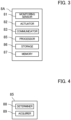
- the first monitor 8A includes a monitoring sensor 81, an actuator 82, a communicator 83, a processor 85, a storage 86, and a memory 87.
- the monitoring sensor 81 is at least one of the camera and other devices described above.
- the monitoring sensor 81 is a camera and a LiDAR sensor.
- the monitoring sensor 81 acquires images and point group data of objects in a predetermined monitoring area as monitoring information.
- the actuator 82 changes orientation of the monitoring sensor 81 to thereby change a monitoring area of the monitoring sensor 81.
- the actuator 82 is, for example, an electric motor.
- the communicator 83 wirelessly communicates with an external device.
- the processor 85 controls the entire first monitor 8A.
- the processor 85 performs various computation processes.
- the processor 85 is a processor such as a central processing unit (CPU).
- the processor 85 may be a micro controller unit (MCU), a micro processor unit (MPU), a field programmable gate array (FPGA), a programmable logic controller (PLC), or system LSI, for example.
- MCU micro controller unit
- MPU micro processor unit
- FPGA field programmable gate array
- PLC programmable logic controller
- system LSI system LSI
- the storage 86 stores programs and various types of data to be executed by the processor 85.
- the storage 86 stores a control program.
- the storage 86 stores position information on the first monitor 8A.
- the storage 86 may be, for example, a nonvolatile memory, a hard disc drive (HDD), or a solid state drive (SSD).
- the memory 87 temporarily stores data or other information.
- the memory 87 is a volatile memory.
- FIG. 4 is a functional block diagram of the processor 85.
- the processor 85 reads programs from the storage 86 and develops the programs to the memory 87 to thereby perform various functions. Specifically, the processor 85 serves as a determiner 88 that determines a monitoring area of the monitoring sensor 81 and an acquirer 89 that acquires monitoring information by the monitoring sensor 81.
- the determiner 88 determines a monitoring area of the monitoring sensor 81 based on a search instruction from the map generator 100 and the map 2. A method for determining the monitoring area will be described later.
- the acquirer 89 causes the monitoring sensor 81 to acquire monitoring information on the monitoring area determined by the determiner 88. Specifically, the acquirer 89 operates the actuator 82 to adjust the monitoring area of the monitoring sensor 81 and acquires monitoring information by the monitoring sensor 81.
- the acquirer 89 stores the acquired monitoring information, time information at acquisition, and position information on the monitoring area, in the storage 86.
- the acquirer 89 transmits the monitoring information, the time information, and the position information stored in the storage 86 to the map generator 100.
- the second monitor 8B continuously acquires monitoring information while moving in the environment, and periodically transmits the acquired monitoring information to the map generator 100.
- the second monitor 8B periodically receives the map 2 from the map generator 100, determines a monitoring area based on the map 2, and acquires monitoring information on the determined monitoring area.
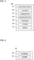
- FIG. 5 illustrates a schematic hardware configuration of the second monitor 8B.
- the second monitor 8B includes a monitoring sensor 91, an actuator 92, a communicator 93, a position detector 94, a processor 95, a storage 96, and a memory 97.
- the monitoring sensor 91 is at least one of the camera and other devices described above.
- the monitoring sensor 91 is a LiDAR sensor or a camera.
- the monitoring sensor 91 acquires point group data and still images of objects in a predetermined monitoring area as monitoring information.
- the actuator 92 moves the monitoring sensor 91 to thereby change a monitoring area of the monitoring sensor 91.
- the actuator 92 is, for example, an electric motor of a plurality of (e.g., four) propellers of a drone.
- the actuator 92 adjusts driving of the propellers to thereby cause the second monitor 8B to fly and change the monitoring area of the monitoring sensor 91.
- the communicator 93 wirelessly communicates with an external device.
- the position detector 94 detects a position of a second monitoring facility 9B.
- the position detector 94 is a global positioning system (GPS) receiver.
- the position detector 94 may include a gyro sensor or an acceleration sensor.
- the processor 95 controls the entire second monitor 8B.
- the processor 95 performs various computation processes.
- the processor 95 is a processor such as a central processing unit (CPU).
- the processor 95 may be a micro controller unit (MCU), a micro processor unit (MPU), a field programmable gate array (FPGA), a programmable logic controller (PLC), or system LSI, for example.
- MCU micro controller unit
- MPU micro processor unit
- FPGA field programmable gate array
- PLC programmable logic controller
- system LSI system LSI
- the storage 96 stores programs and various types of data to be executed by the processor 95.
- the storage 96 stores a control program.
- the storage 96 may be, for example, a nonvolatile memory, a hard disc drive (HDD), or a solid state drive (SSD).
- the memory 97 temporarily stores data or other information.
- the memory 97 is a volatile memory.
- FIG. 6 is a functional block diagram of the processor 95.
- the processor 95 reads programs from the storage 96 and develops the programs to the memory 97 to thereby perform various functions. Specifically, the processor 95 serves as a determiner 98 that determines a monitoring area of the monitoring sensor 91 and an acquirer 99 that acquires monitoring information by the monitoring sensor 91.
- the determiner 98 determines a monitoring area of the monitoring sensor 91 based on a search instruction and the map 2 from the map generator 100. A method for determining the monitoring area will be described later.
- the acquirer 99 causes the monitoring sensor 91 to acquire monitoring information on the monitoring area determined by the determiner 98. Specifically, the acquirer 99 controls the actuator 92 to thereby move the second monitoring facility 9B so that the monitoring area of the monitoring sensor 91 matches the determined monitoring area.
- the acquirer 99 acquires monitoring information on the monitoring area by the monitoring sensor 91.
- the acquirer 99 stores the acquired monitoring information, time information at acquisition, and position information on the monitoring area, in the storage 96.
- the position of the monitoring area is a position of the second monitoring facility 9B detected by the position detector 94.
- the acquirer 99 transmits the monitoring information, the time information, and the position information stored in the storage 96 to the map generator 100.
- the mover 1 is, for example, a vehicle. Alternatively, the mover 1 may be a ship or an autonomous robot.
- FIG. 7 illustrates a schematic hardware configuration of the mover 1.
- the mover 1 includes a monitoring sensor 11, an actuator 12, a communicator 13, a position detector 14, a display 111, a processor 15, a storage 16, and a memory 17.
- the monitoring sensor 11 is at least one of the camera and other devices described above. In this example, the monitoring sensor 11 is a LiDAR sensor.
- the monitoring sensor 11 acquires point group data of objects in a predetermined monitoring area as monitoring information.
- the actuator 12 is a driving source of the mover 1.
- the actuator 12 is an electric motor or an engine.
- the communicator 13 wirelessly communicates with an external device.
- the position detector 14 detects a position of the mover 1.
- the position detector 14 is a global positioning system (GPS) receiver.
- the position detector 14 may include a gyro sensor or an acceleration sensor.
- the display 111 is, for example, a car navigation system.
- the display 111 displays the map 2 as necessary.
- the processor 15 controls the entire mover 1.
- the processor 15 performs various computation processes.
- the processor 15 is a processor such as a central processing unit (CPU).
- the processor 15 may be a micro controller unit (MCU), a micro processor unit (MPU), a field programmable gate array (FPGA), a programmable logic controller (PLC), or system LSI, for example.
- MCU micro controller unit
- MPU micro processor unit
- FPGA field programmable gate array
- PLC programmable logic controller
- system LSI system LSI
- the storage 16 stores programs and various types of data to be executed by the processor 15. For example, the storage 16 stores a control program.
- the storage 16 stores position information on the mover 1.
- the storage 16 may be, for example, a nonvolatile memory, a hard disc drive (HDD), or a solid state drive (SSD).
- the memory 17 temporarily stores data or other information.
- the memory 17 is a volatile memory.
- the processor 15 controls the actuator 12 so that the mover 1 thereby performs autonomous driving.
- the mover 1 receives the map 2 from the map generator 100 through the communicator 13, and generates a route based on the map 2.
- the processor 15 controls the actuator 12 based on detection results by the monitoring sensor 11 and the position detector 14 to cause the mover 1 to move along the generated route.
- the mover 1 periodically receives the map 2 from the map generator 100 and updates the route.
- FIG. 8 is a functional block diagram of the processor 15.
- the processor 15 reads programs from the storage 16 and develops the programs to the memory 17 to thereby perform various functions. Specifically, the processor 15 serves as a route creator 18, a driving executor 19, and a monitoring information acquirer 110.
- the route creator 18 generates a route based on the map 2.
- a destination is set in the mover 1 beforehand.
- the route creator 18 generates a route from a current position of the mover 1 to the destination based on the map 2.
- the route creator 18 refers to the geographical information 21 and the hazardous area information 22 included in the map 2.
- the route creator 18 causes the display 111 to display the map 2.
- the route creator 18 superimposes the hazardous area information 22 on the geographical information 21 and causes the display 111 to display the resulting information.
- the route creator 18 may superimpose the route on the map 2 and cause the display 111 to display the map 2.
- the driving executor 19 controls the actuator 12 such that the mover 1 moves along the generated route.
- the driving executor 19 controls the actuator 12 such that the position of the mover 1 detected by the position detector 14 moves on the generated route.
- the executor 19 controls the actuator 12 to perform avoidance driving of avoiding collision with the obstacle.
- the monitoring information acquirer 110 acquires monitoring information by the monitoring sensor 11.
- the monitoring information acquirer 110 stores the acquired monitoring information, time information at acquisition, and position information on the monitoring area in the storage 16.
- the position of the monitoring area is a position of the mover 1 detected by the position detector 14.
- the monitoring information acquirer 110 transmits the monitoring information, the time information, and the position information stored in the storage 16 to the map generator 100.
- the map generator 100 periodically collects monitoring information from the monitors 8.
- the map generator 100 integrates and processes the monitoring information from the monitors 8 and generates the map 2.
- the map generator 100 periodically generates the map 2 and transmits the map 2 to the mover 1 or the monitors 8.
- the map generator 100 is a computer or a server group.
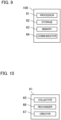
- FIG. 9 illustrates a schematic hardware configuration of the map generator 100.
- the map generator 100 includes a processor 61, a storage 62, a memory 63, and a communicator 64.
- the communicator 64 wirelessly communicates with an external device.
- the processor 61 controls the entire map generator 100.
- the processor 61 performs various processes.
- the processor 61 is a processor such as a central processing unit (CPU).
- the processor 61 may be a micro controller unit (MCU), a micro processor unit (MPU), a field programmable gate array (FPGA), a programmable logic controller (PLC), or system LSI, for example.
- MCU micro controller unit
- MPU micro processor unit
- FPGA field programmable gate array
- PLC programmable logic controller
- system LSI system LSI
- the storage 62 stores programs and various types of data to be executed by the processor 61.
- the storage 62 stores a control program.
- the storage 62 stores geographical information 21 on an environment.
- the storage 62 may be, for example, a nonvolatile memory, a hard disc drive (HDD), or a solid state drive (SSD).
- the memory 63 temporarily stores data or other information.
- the memory 63 is a volatile memory.
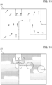
- FIG. 10 is a functional block diagram of the processor 61.
- the processor 61 reads programs from the storage 62 and develops the programs to the memory 63 to thereby perform various functions. Specifically, the processor 61 serves as a collector 65 that collects monitoring information, a recognizer 66 that recognizes an obstacle in the environment from the monitoring information, and a creator 67 that generates the map 2.
- the collector 65 collects monitoring information from the first monitors 8A and the second monitors 8B. In this example, since the mover 1 also has the function of acquiring monitoring information, the collector 65 also collects monitoring information from the mover 1. Specifically, the collector 65 periodically transmits a search instruction for acquiring monitoring information to the first monitors 8A, the second monitors 8B, and the mover 1 together with the map 2 through the communicator 64. The map 2 at this time includes at least the search information 27. The first monitors 8A, the second monitors 8B, and the mover 1 that have received the search instruction and the map 2 acquire monitoring information and transmit the acquired monitoring information to the map generator 100. The collector 65 receives the monitoring information from each of the first monitors 8A, the second monitors 8B, and the mover 1 through the communicator 64 and stores the monitoring information in the storage 62. Since the search instruction is periodically transmitted, the monitoring information is also periodically collected.
- the creator 67 refers to each information and generates the map 2. Specifically, the creator 67 reads the geographical information 21 stored in the storage 62. The creator 67 generates the hazardous area information 22, the obstacle information 25, the disturbance information 26, and the search information 27 based on the obstacles recognized by the recognizer 66.
- FIG. 11 is a schematic view showing an example of the geographical information 21.
- FIG. 12 is a schematic view showing an example of the first hazardous area information 23.
- the geographical information 21 in the geographical information 21, a road is partitioned by buildings and others.
- the geographical information 21 is indicated by chain double-dashed lines for reference.
- regions enclosing obstacles recognized as first obstacles by the recognizer 66 are set as the first hazardous areas 31.
- two first hazardous areas 31a and 31b are set.
- the first hazardous area 31a corresponds to a first obstacle identified as a construction site.
- the first hazardous area 31b corresponds to a first obstacle identified as a rough terrain.
- the creator 67 stores positions and outer shapes of the first hazardous areas 31a and 31b in the storage 62 as the first hazardous area information 23.
- the creator 67 may set an avoidance priority indicating the necessity of avoidance in the first hazardous areas 31. That is, the creator 67 obtains an avoidance priority of the first hazardous areas 31 based on the monitoring information, and sets the avoidance priority in the first hazardous areas 31.
- the creator 67 sets a high avoidance priority in the first hazardous area 31 that should be absolutely avoided, and sets a low avoidance priority in the first hazardous area 31 that should be avoided if possible. For example, the creator 67 sets a high avoidance priority in the first hazardous area 31a corresponding to a construction site, and sets a low avoidance priority in the first hazardous area 31b corresponding to a rough terrain.
- the creator 67 may include non-passable areas as the first hazardous areas 31 in the first hazardous area information 23.
- regions corresponding to a fairway that can be in the opposite direction can be set as the first hazardous areas 31.
- the map generator 100 can acquire information on fairways, passages, or roads defined by a law or a custom from an external database or others.
- FIG. 13 is a schematic view showing an example of the second hazardous area information 24.
- the geographical information 21 is indicated by chain double-dashed lines for reference.
- the creator 67 performs a behavior prediction with a time lapse based on information on, for example, the speeds of obstacles recognized as second obstacles by the recognizer 66, and areas where the second obstacles can be present are set as the second hazardous areas 32.
- the behavior prediction of the second obstacle is executed by various known techniques.
- four second hazardous areas 32a, 32b, 32c, and 32d are set.
- the second hazardous area 32a corresponds to a second obstacle identified as a moving vehicle.
- the second hazardous area 32b corresponds to a second obstacle identified as another moving vehicle.
- the second hazardous area 32c corresponds to a third obstacle identified as yet another vehicle that is stopped.
- the second hazardous area 32d corresponds to the second obstacle identified as a moving person.
- the second hazardous areas 32a and 32b correspond to moving vehicles, and thus, are relatively large.
- the second hazardous area 32c corresponds to a stationary vehicle, and thus, is relatively small, and a uniform avoidance priority is set in all the directions.
- the second hazardous area 32d corresponds to a person, and thus, is smaller than the second hazardous areas 32a and 32b.
- the creator 67 may also set an avoidance priority in the second hazardous areas 32, in a manner similar to the first hazardous areas 31. That is, the creator 67 obtains an avoidance priority of the second hazardous areas 32 based on the monitoring information, and sets the avoidance priority in the second hazardous areas 32. For example, the creator 67 sets a low avoidance priority in the second hazardous area 32 corresponding to the second obstacle showing a stable behavior, and sets a high avoidance priority in the second hazardous area 32 corresponding to the second obstacle showing an unstable behavior. In a case where a mover passing in a passage prohibited area is identified as the second obstacle, the creator 67 sets a high avoidance priority in the second hazardous area 32 corresponding to this mover.
- the creator 67 may change the avoidance priority in the second hazardous area 32. That is, the avoidance priority in the second hazardous area 32 may not be uniform.
- the creator 67 obtains an avoidance priority within the second hazardous area 32 based on the monitoring information and sets the avoidance priority in the second hazardous area 32. Since the second hazardous areas 32 are set based on behavior prediction of second obstacles, existence probability of second obstacles varies even in the second hazardous areas 32.
- a high avoidance priority is set in a portion of the second hazardous area 32 with a high existence probability of a second obstacle, such as a portion close to the current position of the second obstacle, whereas a low avoidance priority is set in a portion with a low existence probability of a second obstacle, such as a portion away from the current position of the second obstacle.
- avoidance priorities in three stages are used, solid lines indicate portions with high avoidance priority, chain lines indicate portions with intermediate avoidance priority, and broken lines indicate portions with low avoidance priority.
- the creator 67 obtains a predicted distribution by using a filter such as a Kalman filter or a Bayesian filter.
- a filter such as a Kalman filter or a Bayesian filter.
- x t + 1 f x t u t ⁇ + ⁇
- x t is a state quantity of a second obstacle at time t
- u t is an input (speed or acceleration) of the second obstacle at time t
- ⁇ is a parameter of a motion model such as mass or viscous force
- ⁇ is a disturbance of, for example, random noise.
- the creator 67 uses a prediction model below for each second obstacle.
- p x t + 1 ⁇ , ⁇ , ⁇ ⁇ p x t + 1 x t , u t , ⁇ , ⁇ p x t u t ⁇ dx t du t
- ⁇ , ⁇ , ⁇ ) is a posterior distribution of x t+1
- ⁇ ) is a prior distribution of x t
- x t , ut, ⁇ , ⁇ ) is a probability motion model
- ⁇ and ⁇ are parameters of the motion model.
- parameters ⁇ , ⁇ , and ⁇ of the motion model need to be set, and the creator 67 estimates the parameters ⁇ , ⁇ , and ⁇ .
- the creator 67 estimates the parameters based on the type and outer shape of a second obstacle.
- wave drag that is the dominant resistance of the ship can be estimated from the speed and ship shape (Froude number and wave drag coefficient). Therefore, the creator 67 can estimate the parameters ⁇ , ⁇ , and ⁇ as functions of the ship type and speed.
- the creator 67 estimates a motion model or a distribution of input by using data data-driven control. For example, the creator 67 estimates a stochastic motion model and an input distribution by machine learning (e.g., Gaussian process or Bayes estimation) using past trajectory data. The creator 67 can calculate a predicted distribution of a second obstacle by a sampling method such as a markov chain monte carlo (MCMC) method. Alternatively, the creator 67 approximates a predicted distribution of a second obstacle by, for example, moment matching.
- MCMC markov chain monte carlo
- the creator 67 may predict a trajectory of a second obstacle by using a database other than a motion model.
- the creator 67 may stochastically predict the trajectory from a database of past trajectories of the second obstacle.
- the creator 67 may compare the trajectory of the second obstacle with past trajectories in the database to perform sampling based on likelihood.
- the creator 67 may also set one second hazardous area 32 based on multiple second obstacles. For example, the creator 67 performs clustering on second obstacles based on position and moving direction, and approximates a cluster speed distribution by moment matching or other techniques from an average speed and a speed distribution of second obstacles in a cluster. The creator 67 may derive a predicted distribution of a cluster from the approximated speed distribution to set the second hazardous area 32. For example, in a congestion range where second obstacles are congested, setting of the second hazardous area 32 is simplified.
- the creator 67 generates obstacle information 25 based on obstacles.
- FIG. 14 is a schematic view showing an example of the obstacle information 25.
- the geographical information 21 is indicated by chain double-dashed lines for reference.
- the creator 67 stores the positions, speeds, types, sizes, and shapes of obstacles recognized as second obstacles by the recognizer 66, in the storage 62 as the obstacle information 25.
- the creator 67 may also store a speed dispersion of the second obstacle in the storage 62 as the obstacle information 25.
- the creator 67 may also store parameters of the motion model used in obtaining the second hazardous area 32 in the storage 62 as the obstacle information 25 of corresponding second obstacles.
- the obstacle information 25 includes four second obstacles.
- FIG. 14 schematically illustrates the position and speed of each second obstacle.
- a second obstacle 41a is a moving vehicle.
- a second obstacle 41b is another moving vehicle.
- a second obstacle 41c is yet another vehicle that is stopped.
- a second obstacle 41d is a moving person.
- FIG. 15 is a schematic view showing an example of the disturbance information 26.
- the geographical information 21 is indicated by chain double-dashed lines for reference.
- the creator 67 generates the disturbance information 26 based on information on disturbance from the mover 1 or the monitors 8.
- the disturbance is, for example, an airflow direction and a wind velocity.
- the disturbance may be tidal current.
- the creator 67 represents the disturbance information 26 as a vector field as shown in FIG. 15 .
- the mover 1 or the monitor 8 can measure an airflow direction and a wind velocity in the environment.
- the mover 1 or the second monitor 8B measures the airflow direction and the wind velocity at each point while moving in the environment.
- the first monitor 8A measures am airflow direction and a wind velocity at a point at which the first monitor 8A is placed.
- the map generator 100 collects position information, an airflow direction, and a wind velocity at a measurement point from the mover 1 or the monitor 8.
- the monitoring sensor for detecting an airflow direction and a wind velocity is not limited to an anemometer and may be a camera such as an infrared camera.
- the infrared camera can take an image of steam or smoke in the environment, and based on steam or smoke, an airflow direction and a wind velocity can be derived.
- the creator 67 may collect disturbance obtained by the disturbance observer from the mover 1 or the second monitor 8B.
- an underwater drone may be employed as the second monitor 8B.
- the creator 67 may obtain tidal current based on disturbance obtained by a disturbance observer of the underwater drone or on a water-resistance speed by a doppler velocity log (DVL).
- the creator 67 may estimate a vector field in the environment from actually obtained vectors of disturbances by using a model obtained through machine learning. Alternatively, the creator 67 may interpolate vectors of disturbances at each point in the environment by a technique such as Gaussian process from actually obtained vectors of disturbance.
- FIG. 16 is a schematic view showing an example of the search information 27.
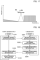
- FIG. 17 is a graph showing a monitoring priority change.
- the geographical information 21 is indicated by chain double-dashed lines for reference.
- the creator 67 generates the search information 27 based on the monitoring information from the monitor 8.
- the search information 27 is information related to a monitoring priority at each position in the environment.
- the creator 67 sets a monitoring priority at each position in accordance with an elapsed time since monitoring information at each position was acquired. As the time passes after the monitoring information is acquired, the monitoring priority increases.
- the monitoring priority is represented by the density of dots. A region with a high dot density has a high monitoring priority, and a region with a low dot density has a low monitoring priority.
- the creator 67 sets a monitoring priority ⁇ (q, t) at each position q in an environment Q as a function of the position q and a time t.
- the monitoring priority ⁇ gradually increases with the elapsed time since the monitoring information was acquired, and decreases when the monitoring information is acquired, as represented by equation below.
- the ordinate represents a monitoring priority ⁇
- the abscissa represents a position q.
- the second monitor 8B moves from the left to the right along the abscissa while acquiring monitoring information.
- a monitoring priority ⁇ at a position q at which monitoring information is acquired by the second monitor 8B is low, and a monitoring priority ⁇ at a position q at which monitoring information is not acquired yet is high.
- a monitoring priority ⁇ at a position q at which monitoring information has been already acquired increases with a lapse of time.
- the time constants ⁇ d (q) and ⁇ u (q) may be values different in accordance with the position q. For example, for a position q with a large number of past accidents, the time constant ⁇ u (q) may be set such that 1/ ⁇ u (q) is larger than those at the other positions q.
- the creator 67 basically changes the monitoring priority ⁇ according to Equation (3). However, the creator 67 may change the monitoring priority ⁇ uniquely in accordance with a specific event, irrespective of Equation (3). For example, the creator 67 may predict a trajectory of the mover 1 to set a high monitoring priority ⁇ at a position q on the predicted trajectory. Accordingly, the monitoring priority ⁇ on a future trajectory of the mover 1 increases. In a case where an unidentified mover with an unknown ID or other details is detected, the creator 67 may set a high monitoring priority ⁇ at a position near the unidentified mover to follow the unidentified mover. To increase the monitoring priority ⁇ , the time constant ⁇ u (q) may be increased without directly changing the monitoring priority ⁇ . Accordingly, an increase rate of the monitoring priority ⁇ at a specific position q increases, and the monitoring priority ⁇ increases in an early stage.
- the driving assistance system 1000 performs a monitoring process of collecting monitoring information at each position in the environment.
- the map generator 100 transmits a search instruction to the monitors 8, and the monitors 8 acquire monitoring information and transmit the monitoring information to the map generator 100.
- FIG. 18 is a flowchart of the monitoring process.
- the map generator 100 and the monitors 8 perform the monitoring process according to the flowchart of FIG. 18 .
- the monitors 8 periodically exchange position information each other and each recognize positions of the other monitors 8.
- the map generator 100 transmits a search instruction and a map 2 for search to the monitors 8.
- the map 2 for search includes at least the search information 27.
- the map 2 also includes the geographical information 21.
- the map 2 is common to all the monitors 8.
- the map generator 100 generates the search information 27 based on currently acquired monitoring information.
- the creator 67 obtains a monitoring priority ⁇ from Equation (3) based on an elapsed time t since monitoring information at each position q in the environment was acquired, and generates the search information 27.
- the creator 67 reads the geographical information 21 from the storage 62, and generates the map 2 including the geographical information 21 and the search information 27.
- the map generator 100 transmits the search instruction and the map 2 to all the monitors 8. At this time, the map generator 100 may also transmit search instruction and the map 2 to the mover 1 having the function of acquiring monitoring information.
- the monitors 8 receive the search instruction and the map 2 in step S201.
- each of the monitors 8 determines a monitoring area for which monitoring information should be acquired, based on the search information 27.
- Each monitor 8 determines a monitoring area based on the search information 27 such that the overall monitoring priority ⁇ in the environment decreases.
- the search information 27 includes the monitoring priority ⁇ (q, t) or a partial differentiation of the monitoring priority ⁇ (q, t) represented by Equation (3).
- each monitor 8 determines a monitoring area such that the overall priority J in the equation below decreases, and sets a speed (specifically speed vector) u i of the monitor 8.
- a monitoring area is set in an area with a high monitoring priority ⁇ in the environment.
- each monitor 8 determines a monitoring area by performing cooperative control with other monitors 8.
- the second monitor 8B is aware of positions of the first monitor 8A and the other second monitors 8B.
- the second monitor 8B sets monitoring information in an area with a high monitoring priority ⁇ located relatively near the second monitor 8B itself.
- the second monitor 8B allows the other monitors 8 to acquire monitoring information on this area. Since the first monitor 8A cannot move, the first monitor 8A determines a monitoring area within the monitorable range of the first monitor 8A itself. In this manner, the monitor 8 determines a monitoring range in cooperation with other monitors 8.
- the monitor 8 acquires monitoring information in step S203. Specifically, the first monitor 8A adjusts the direction (e.g., field of view (FOV) of a LiDAR sensor) of the monitoring sensor 81 to the monitoring area, and the monitoring sensor 81 acquires monitoring information.
- the second monitor 8B moves such that the FOV of the monitoring sensor 91 matches the monitoring area, and the monitoring sensor 91 acquires monitoring information.
- the second monitor 8B refers to the geographical information 21 and generates a route that does not collide with buildings or planimetric features.
- the mover 1 with the function of acquiring monitoring information acquires monitoring information necessary for autonomous driving in the case of executing autonomous driving. That is, the mover 1 acquires monitoring information, irrespectively of the monitoring priority ⁇ .
- step S204 the monitor 8 transmits the acquired monitoring information to the map generator 100.
- step S102 the map generator 100 receives the monitoring information.
- the map generator 100 collects monitoring information from the monitors 8 in the environment.
- the map generator 100 updates the search information 27 in step S103. Specifically, the map generator 100 decreases the partial differentiation of the monitoring priority ⁇ (q, t) at a point at which monitoring information is acquired according to the upper expression in Equation (3), and increases the partial differentiation of the monitoring priority ⁇ (q, t) at a point at which no monitoring information is acquired according to the lower expression in Equation (3). In this manner, the search information 27 is updated.
- the map generator 100 repeats processes from step S101 by using the updated search information 27.
- the search information 27 is updated such that the monitoring priority ⁇ increases with the elapsed time since the monitoring information was acquired, and based on the updated search information 27, the monitors 8 acquires monitoring information on areas with high monitoring priority ⁇ with priority.
- the number of points that are left without monitoring for a long period in the environment decreases so that monitoring information in the environment can be thereby kept up-to-date.
- the driving assistance system 1000 performs a map generation process of generating the map 2 for driving assistance based on monitoring information in the environment.
- the map generator 100 generates the map 2 based on the monitoring information.
- the map 2 for driving assistance includes at least the geographical information 21 and the hazardous area information 22.
- the map 2 includes the first hazardous area information 23 and the second hazardous area information 24 as the hazardous area information 22.
- the map 2 also includes the obstacle information 25 and the disturbance information 26.
- the map 2 is common to all the movers 1.
- the map generator 100 may generate the map 2 in a form including all the geographical information 21, the hazardous area information 22, the obstacle information 25, and the disturbance information 26.
- the map generator 100 may generate different types of maps 2 including different types of information, such as a map 2 including the geographical information 21 and the hazardous area information 22, a map 2 including the geographical information 21 and the obstacle information 25, and the map 2 including the disturbance information 26.
- the map 2 includes the geographical information 21, the first hazardous area information 23, the second hazardous area information 24, the obstacle information 25, and the disturbance information 26.
- the map generator 100 periodically collects monitoring information from the monitors 8 and periodically updates the map 2.
- the map generator 100 periodically transmits the map 2 to the mover 1.
- the collection period of the monitoring information, the update period of the map 2, and the transmission period of the map 2 may be or may not be synchronized.
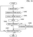
- FIG. 19 is a flowchart of autonomous driving.
- the mover 1 performs autonomous driving according to the flowchart of FIG. 19 .
- the mover 1 receives the map 2.
- the map 2 includes the geographical information 21, the first hazardous area information 23, the second hazardous area information 24, the obstacle information 25, and the disturbance information 26.
- step S302 the mover 1 generates a route 5 based on the map 2.
- a destination 51 is set for the mover 1.
- a transit point 52 is set for the mover 1 in some cases.
- the route creator 18 generates the entire route 5 from the current location to the destination 51 based on the geographical information 21 and the first hazardous area information 23.
- the route creator 18 generates the route 5 from the current location to the destination 51 by way of the transit point 52.
- the route creator 18 generates the route 5 in consideration of influence of disturbance based on the disturbance information 26.
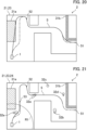
- FIG. 20 is a schematic view of a map 2 in which the first hazardous area information 23 is superimposed on the geographical information 21.
- the route creator 18 of the mover 1 basically generates the route 5 from the current location to the destination based on the geographical information 21.
- the route creator 18 first generates a route 5 as indicated by the solid line in FIG. 20 .
- the route creator 18 refers to the geographical information 21 and generates a route that does not collide with planimetric features or other obstacles. In a case where a road, a passage, or a fairway is set in the environment, the route creator 18 generates a route along the road, the passage, or the fairway.
- the route creator 18 also refers to the disturbance information 26 and generates a route 5 that avoids areas such as a strong wind area.
- the route creator 18 generates a route by using an A-star search algorithm, a hybrid A-star search algorithm, or an RRT-star search algorithm.
- the route creator 18 modifies the route 5.
- the route 5 generated only from the geographical information 21 passes on the first hazardous area 31a and also passes near the first hazardous area 31b.
- the route creator 18 modifies the route 5 such that the route 5 bypasses the first hazardous area 31a and passes away from the first hazardous area 31b.
- the route creator 18 also refers to the geographical information 21 to modify the route 5 such that the route 5 avoids interference with planimetric features and other obstacles.
- the route creator 18 may determine whether to bypass the first hazardous areas 31, how far the route 5 and the first hazardous areas 31 should be kept apart, and others, based on the avoidance priority. For example, a relatively high avoidance priority is set in the first hazardous area 31a, and a relatively low avoidance priority is set in the first hazardous area 31b. In this case, the route creator 18 may modify the route 5 such that the route 5 bypasses the first hazardous area 31a and does not bypass the first hazardous area 31b. Alternatively, the route creator 18 may modify the route 5 such that the route 5 greatly bypasses the first hazardous area 31a and slightly bypasses the first hazardous area 31b.
- step S303 the route creator 18 locally modifies the route 5. Specifically, the route creator 18 modifies the route 5 based on the second hazardous area information 24.
- FIG. 21 is a schematic view of the map 2 in which the first hazardous area information 23 and the second hazardous area information 24 are superimposed on the geographical information 21.
- the route creator 18 determines based on the second hazardous area information 24 whether the second hazardous area 32 is present or not on or near the route 5 within a predetermined first range R1 from the current location of the mover 1.
- the second hazardous area 32e is located on the route 5 within the first range R1.
- the route creator 18 modifies the route 5 such that the route 5 bypasses the second hazardous area 32e.
- the route creator 18 sets a local destination (i.e., waypoint) 53 on a route 5 outside the first range R1, and as indicated by the chain line, modifies the route 5 such that the route 5 bypasses the second hazardous area 32e while heading toward the waypoint 53.
- the route creator 18 also refers to the geographical information 21 and the first hazardous area information 23 and modifies the route 5 such that the route 5 avoids interference with the planimetric features and other obstacles and the first hazardous area 31.
- the route creator 18 may also refer to the disturbance information 26. For example, the route creator 18 may search for a route with high energy efficiency in consideration of dynamics of the mover 1 and disturbance.
- the second hazardous area 32a is also located on the route 5, the second hazardous areas 32a is outside the first range R1, and thus, the route creator 18 does not modify the route 5 corresponding to the second hazardous area 32a.
- the route creator 18 generates a route 4 in consideration of the first hazardous areas 31 within and outside the first range R1 for the first hazardous areas 31, whereas the route creator 18 generates a route 4 in consideration of only the second hazardous areas 32 within the first range R1 for the second hazardous areas 32. That is, since the first hazardous areas 31 hardly change with time, the route creator 18 considers the first hazardous areas 31 ranging to locations relatively far from the mover 1. On the other hand, since the second hazardous areas 32 can change with time, the route creator 18 considers only the second hazardous areas 32 relatively close to the mover 1.
- the route creator 18 may determine, for example, whether to bypass the second hazardous areas 32, how far the second hazardous areas 32 and the route 5 should be kept apart, and others, based on the avoidance priority. For example, in a case where there is the second hazardous area 32 where a mover passing in a passage prohibited area corresponds to a second obstacle, a relatively high avoidance priority is set in this second hazardous area 32. In this case, the route creator 18 may modify the route 5 such that the route 5 bypasses this second hazardous area 32 with priority or greatly bypasses this second hazardous area 32 as compared to the other second hazardous areas 32.
- the route creator 18 can determine a portion that should be definitely avoided and a portion that should be avoided if possible within the second hazardous area 32. For example, the route creator 18 may modify the route 5 such that the route 5 greatly bypasses a portion with a high avoidance priority and slightly bypasses a portion with a low avoidance priority within the second hazardous area 32. Alternatively, the route creator 18 may modify the route 5 such that the route 5 bypasses a portion with a high avoidance priority and passes only a portion with a low avoidance priority within the second hazardous area 32.
- the mover 1 moves in step S304.
- the driving executor 19 performs feedback control on the actuator 12 such that the mover 1 moves along the route 5 with reference to detection results of the monitoring sensor 11 and the position detector 14.
- step S305 the mover 1 determines whether avoidance operation is necessary, based on the map 2.
- the driving executor 19 determines whether there is an obstacle for which collision is to be avoided, based on the obstacle information 25 in the map 2.
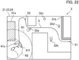
- FIG. 22 is a schematic view of the map 2 in which a behavior of an obstacle predicted based on the obstacle information 25 is superimposed on the geographical information 21. In FIG. 22 , the first hazardous area information 23 and the second hazardous area information 24 are also superimposed.
- the driving executor 19 determines whether an obstacle is present within a predetermined second range R2 from the current location of the mover 1, based on the obstacle information 25.
- the second range R2 is narrower than the first range R1.
- the driving executor 19 predicts a behavior of the obstacle and determines whether there is a possibility that the obstacle interferes with the mover 1.
- obstacles 41e and 41f are present within the second range R2.
- the driving executor 19 estimates predicted trajectories of the obstacles. In a manner similar to the creator 67, the driving executor 19 may estimate predicted trajectories of the obstacles 41e and 41f by using parameters and others of a motion model.
- the driving executor 19 performs avoidance operation based on the obstacle information 25.
- the driving executor 19 performs feedback control on the position of the mover 1 such that the mover 1 avoids the predicted trajectory of the obstacle 41e or 41f.
- the driving executor 19 controls the mover 1 by using a model predictive control (MPC) or control barrier function (CBF).
- MPC model predictive control
- CBF control barrier function
- the mover 1 moves out of the route 5 to avoid the obstacle 41e or 41f.
- the mover 1 stops or decelerates to avoid collision with the obstacle 41e or 41f.
- the route creator 18 also refers to the geographical information 21 and the first hazardous area information 23 and moves the mover 1 such that the mover 1 avoids interference with the planimetric features and other obstacles and the first hazardous areas 31.
- a motion executor 19 may calculate an executable operation amount obtaining both disturbance compensation and avoidance in consideration of influence of disturbance, and operate the actuator 12 with the calculated executable operation amount.
- the driving executor 19 determines whether the mover 1 has reached the destination 51 in step S307. In a case where the mover 1 has not reached the destination 51 yet, the mover 1 returns to step S301 and repeats the process from step S301. In a case where the mover 1 has reached the destination 51, the mover 1 finishes autonomous driving.
- the mover 1 in the autonomous driving, the mover 1 generates and modifies the route 5 based on the map 2 received from the map generator 100, and performs avoidance operation as necessary, to thereby autonomously move without interference with an obstacle and other hazards to the destination 51.
- the mover 1 periodically receives the updated map 2 to thereby generate and modify the route 5 and perform avoidance operation based on the latest map 2.
- the hazardous area information 22 is obtained based on monitoring information in the environment, and the map 2 including the geographical information 21 and the hazardous area information 22 is generated.
- the use of the map 2 eases generation of the route 5.
- the map generator 100 obtains the hazardous areas 3 based on the monitoring information, and generates the hazardous area information 22.
- the route 5 By generating the route 5 while treating the hazardous areas 3 as areas to be avoided when generating the route 5 based on the geographical information 21, it is possible to generate the route 5 that avoids interference with obstacles and other hazards in the environment. Since it is unnecessary to perform identification of obstacles, behavior prediction of obstacles, and other processes, the route 5 can be easily generated.
- the map generator 100 Since the map generator 100 generates the hazardous areas 3 corresponding to motion of obstacles, the map generator 100 generates the route 5 in consideration of the hazardous area 3 to thereby enable generation of the route 5 that can avoid interference with dynamic obstacles. Specifically, the map generator 100 predicts behaviors of dynamic obstacles and generates the second hazardous areas 32 including predicted behaviors of the obstacles. That is, the predicted behaviors of dynamic obstacles are represented in the form of second hazardous areas 32. By generating the route 5 avoiding the second hazardous areas 32, the route 5 avoiding interference with dynamic obstacles can be easily generated without behavior prediction of obstacles in generating the route 5.
- the map generator 100 classifies the hazardous areas 3 into the first hazardous areas 31 corresponding to static obstacles and the second hazardous areas 32 corresponding to dynamic obstacles. This enables the hazardous areas 3 to be appropriately reflected in generation of the route 5. Specifically, by classifying the hazardous areas 3 into the first hazardous areas 31 and the second hazardous areas 32, information on motion of obstacles is added to the hazardous areas 3. Accordingly, in generating the route 5, the hazardous areas 3 can be appropriately selected and reflected. For example, since the second hazardous areas 32 correspond to dynamic obstacles, the second hazardous areas 32 might change with time. Thus, the second hazardous areas 32 are preferably reflected in relatively short-term route planning. On the other hand, since the first hazardous areas 31 correspond to static obstacles, the first hazardous areas 31 hardly change with time. Thus, the first hazardous areas 31 are preferably reflected in relatively long-term route planning. By generating the route 5 using the first hazardous areas 31 and the second hazardous areas 32 appropriately, the route 5 can appropriately avoid obstacles.
- the map generator 100 obtains an avoidance priority of a hazardous area based on monitoring information and sets the avoidance priority in the hazardous area. Accordingly, the hazardous area can be appropriately reflected in generation of the route 5. Specifically, it is possible to determine whether to reflect the hazardous area in generation of the route 5 based on the avoidance priority. Generation of the route 5 is subjected to various constraints. The hazardous area is one of the constraints. Based on the avoidance priority of the hazardous area, priority of the hazardous area in reflecting the hazardous area in generation of the route 5 can be determined.
- the map generator 100 obtains avoidance priority within the hazardous area based on the monitoring information and sets the avoidance priority in the hazardous area. That is, different avoidance priorities can be given in the hazardous area. Accordingly, the hazardous area can be appropriately reflected in generation of the route 5. Specifically, for one hazardous area, a portion that should be definitely avoided and a portion that should be avoided if possible are determined based on the avoidance priority within the hazardous area.
- the map generator 100 obtains the obstacle information 25 and adds the obstacle information 25 to the map. Accordingly, avoidance operation necessary for movement of the mover 1 along the route 5 can be performed. In route planning, even if a route 5 that avoids obstacles is generated, another obstacle that needs to be avoided might appear during actual movement. Thus, the obstacle information 25 as well as the hazardous area is also added to the map 2 so that the mover 1 can perform avoidance operation based on the obstacle information 25.
- the map generator 100 obtains the disturbance information 26 and adds the disturbance information 26 to the map 2. Accordingly, the route 5 can be generated in consideration of disturbance as well as the hazardous area 3. While the mover 1 is moving, the mover 1 can be affected by disturbance. Generation of the route 5 based on the map 2 enables generation of the route 5 in consideration of influence of disturbance.
- the map generator 100 obtains the search information 27 concerning monitoring priority at each position in the environment and adds the search information 27 to the map 2. Accordingly, the monitor 8 can determine an area for which monitoring information is acquired in the environment, based on the search information 27. As a result, the map generator 100 can appropriately collect monitoring information in the environment.
- the monitoring priority is set in accordance with an elapsed time since monitoring information was acquired at each position in the environment. Accordingly, based on the elapsed time since the monitoring information was acquired, priority of an area for which monitoring information is acquired is determined. Accordingly, the overall monitoring information in the environment can be kept as up-to-date as possible.
- a monitor 9 performs cooperative control with other monitors 9 in determining an area for which monitoring information is acquired, based on the search information 27. Specifically, the monitor 9 near an area with high monitoring priority acquires monitoring information on this area. The monitor 9 appropriately shares acquisition of monitoring information in the environment in cooperation with other monitors 9. As a result, the overall monitoring information in the environment can be kept as up-to-date as possible.
- the mover 1 and the monitor 8 in the driving assistance system 1000 are not limited to those of the example described above.
- the mover 1 is not limited to a vehicle, and may be an autonomous robot (e.g., carrier pallet), a ship, or a flying device (e.g., drone), for example.
- the second monitor 8B may be a vehicle or an underwater drone.
- the number of the movers 1 and the number of the monitors 8 included in the driving assistance system 1000 are not limited to those in the example of FIG. 1 , and may be any numbers.
- the number of the first monitors 8A and the number of the second monitors 8B are also any numbers. For example, one of the first monitors 8A or the second monitors 8B may be omitted.
- the map generator 100 may not be fixed.
- the map generator 100 may be mounted on a mover to move together with the mover.
- the map generator 100 may be mounted on a ship.
- the map generator 100 may collect monitoring information from nearby drones or other ships, and based on the monitoring information, may transmit the map 2 to the nearby movers 1.
- the map 2 may not include all the types of information.
- the map 2 may include at least one of the first hazardous area information 23 or the second hazardous area information 24, as the hazardous area information 22.
- the map 2 may not include at least one of the obstacle information 25 or the disturbance information 26.
- the map 2 for search includes at least the search information 27.
- the map 2 for search may not include the geographical information 21.
- the way of obtaining each type of information included in the map 2 and the way of expression thereof are not limited to those in the example described above.
- the second hazardous area 32 is expressed as a shape obtained by overlaying three circles with different diameters, but is not limited to this example.
- the second hazardous area 32 may be an oval or a square with a smooth outer shape.
- Circuitry, a unit, and means herein are hardware that is programmed to perform or performs the described functions.
- the hardware may be any hardware disclosed herein, or any hardware programmed or known to perform the functions described.
- the hardware is a processor considered to be of a type of circuitry
- the circuitry, means, or a unit is a combination of hardware and software used to configure the hardware and/or the processor.
- the monitor 8 can determine a point at which the monitoring information should be acquired in the environment, based on an elapsed time since the monitoring information was acquired. For example, the monitor 8 acquires monitoring information at a point with a long-elapsed time since the monitoring information was acquired with priority. Accordingly, the map generator 100 can kept the overall monitoring information in the environment as up-to-date as possible.
Landscapes
- Engineering & Computer Science (AREA)
- Radar, Positioning & Navigation (AREA)
- Remote Sensing (AREA)
- Physics & Mathematics (AREA)
- General Physics & Mathematics (AREA)
- Automation & Control Theory (AREA)
- Transportation (AREA)
- Mechanical Engineering (AREA)
- Human Computer Interaction (AREA)
- Chemical & Material Sciences (AREA)
- Analytical Chemistry (AREA)
- Life Sciences & Earth Sciences (AREA)
- Atmospheric Sciences (AREA)
- Mathematical Physics (AREA)
- Traffic Control Systems (AREA)
- Navigation (AREA)
Abstract
Description
- The technique disclosed here relates to a map generator and a driving assistance system.
-
Patent Document 1, for example, discloses a self-driving support system. In this self-driving support system, vehicles share common road map data. Each vehicle calculates a relative position with respect to a reference point in the road map data and outputs the relative position to other vehicles. Each vehicle compares the reference point in the road map data with relative positions of other vehicles to determine positions of the other vehicles. Based on the obtained positions of the other vehicles, each vehicle performs autonomous driving to avoid collision with the other vehicles. - Patent Document 1:
Japanese Patent Application Publication No. 2019-132988 - In the system described above, vehicles generate routes in autonomous driving. In this generation, each vehicle determines a possibility of collision with other vehicles based on relative position information with respect to the other vehicles. This increases a processing load such as a calculation load in generating a route by the vehicle.
- It is therefore an object of the technique disclosed here to reduce a processing load such as a calculation load in generating a route.
- A map generator according to the present disclosure includes: a collector that collects monitoring information in an environment; and a creator that generates a map for assisting autonomous driving of a mover based on the monitoring information, wherein the creator obtains a hazardous area that is included in the environment and to be avoided, based on the monitoring information, and generates the map including geographical information and the hazardous area.
- A driving assistance system according to the present disclosure includes: a mover that performs autonomous driving; and a map generator that generates a map for assisting autonomous driving of the mover, wherein the map generator includes a collector that collects monitoring information in an environment, and a creator that generates the map based on the monitoring information, the creator obtains a hazardous area that is included in the environment and to be avoided based on the monitoring information, generates the map including geographical information and the hazardous area, and transmits the map to the mover, and the mover generates a route of autonomous driving based on the geographical information and the hazardous area.
- A "map" herein is not limited to an expression as an actual diagram, and is a concept also including data formats. That is, the "map" can be regarded as "map information" or "map data."
- The map generator can reduce a processing load such as a calculation load in generating a route.
- The driving assistance system can reduce a processing load such as a calculation load in generating a route.
-
- [
FIG. 1] FIG. 1 is a schematic view of a driving assistance system. - [
FIG. 2] FIG. 2 illustrates a configuration of a map. - [
FIG. 3] FIG. 3 illustrates a schematic hardware configuration of a first monitor. - [
FIG. 4] FIG. 4 is a functional block diagram of a processor of the first monitor. - [
FIG. 5] FIG. 5 illustrates a schematic hardware configuration of a second monitor. - [
FIG. 6] FIG. 6 is a functional block diagram of a processor of the second monitor. - [
FIG. 7] FIG. 7 illustrates a schematic hardware configuration of a mover. - [
FIG. 8] FIG. 8 is a functional block diagram of a processor of the mover. - [
FIG. 9] FIG. 9 illustrates a schematic hardware configuration of a map generator. - [
FIG. 10] FIG. 10 is a functional block diagram of a processor of the map generator. - [
FIG. 11] FIG. 11 is a schematic view showing an example of geographical information. - [
FIG. 12] FIG. 12 is a schematic view showing an example of first hazardous area information. - [
FIG. 13] FIG. 13 is a schematic view showing an example of second hazardous area information. - [
FIG. 14] FIG. 14 is a schematic view showing an example of obstacle information. - [
FIG. 15] FIG. 15 is a schematic view showing an example of disturbance information. - [
FIG. 16] FIG. 16 is a schematic view showing an example of search information. - [
FIG. 17] FIG. 17 is a graph showing a monitoring priority change. - [
FIG. 18] FIG. 18 is a flowchart of a monitoring process. - [
FIG. 19] FIG. 19 is a flowchart of autonomous driving. - [
FIG. 20] FIG. 20 is a schematic view of a map in which first hazardous area information is superimposed on geographical information. - [
FIG. 21] FIG. 21 is a schematic view of a map in which first hazardous area information and second hazardous area information are superimposed on geographical information. - [
FIG. 22] FIG. 22 is a schematic view of a map in which a behavior of an obstacle predicted based on obstacle information is superimposed on geographical information. - An exemplary embodiment will be described in detail hereinafter with reference to the drawings.
FIG. 1 is a schematic view of adriving assistance system 1000. Thedriving assistance system 1000 includes amover 1 that performs autonomous driving, a monitor 8 that acquires monitoring information in an environment, and amap generator 100 that generates amap 2 for assisting autonomous driving. Thedriving assistance system 1000 may includemovers 1. Themap generator 100 is communicably connected to themover 1 and the monitor 8. Themap generator 100 transmits and receives various types of information to/from themover 1 and the monitor 8. Themap generator 100 generates themap 2 for assisting driving of themover 1 based on monitoring information acquired by the monitor 8, and transmits the generatedmap 2 to themover 1. Themover 1 generates a route based on themap 2 and performs autonomous driving. Themap generator 100 generates themap 2 for assisting acquisition of monitoring information by the monitor 8, and transmits the generatedmap 2 to the monitor 8. The monitor 8 acquires monitoring information based on themap 2 and transmits the acquired monitoring information to themap generator 100. Communication of themap generator 100 with themover 1 and the monitor 8 is performed through arelay 121. Themap generator 100 is connected to therelay 121 through a communication network N such as the Internet. Therelay 121 performs wireless communication to themover 1 and the monitor 8. - First, a map generated by the
map generator 100 will be described.FIG. 2 illustrates a configuration of themap 2. - The
map 2 includesgeographical information 21 andhazardous areas 3. Specifically, themap 2 includes thegeographical information 21 andhazardous area information 22. Thehazardous area information 22 is information on thehazardous areas 3 that are included in an environment and should be avoided. Themap 2 may further includeobstacle information 25 anddisturbance information 26. Theobstacle information 25 is information on motion of obstacles. Thedisturbance information 26 is information on disturbance of autonomous driving of themover 1. Themap 2 for use in acquiring monitoring information includessearch information 27. Thesearch information 27 is information on a monitoring priority at each position in the environment. - The
geographical information 21 includes at least one of roads, passages, or planimetric features (objects located on land or at sea, whether natural or artificial, such as buildings, trees, and rocks). Thegeographical information 21 is information on general maps such as road maps, facility maps, and fairway maps. Thegeographical information 21 may be static information. Although thegeographical information 21 can change because of factors such as road alterations, building demolition, or rock erosion, thegeographical information 21 is basically permanent information. Thegeographical information 21 has a coordinate system common to each of thehazardous area information 22, theobstacle information 25, thedisturbance information 26, and thesearch information 27. That is, positions in each of thehazardous area information 22, theobstacle information 25, thedisturbance information 26, and thesearch information 27 correspond to positions on thegeographical information 21. - The
hazardous area information 22 is information on positions and outer shapes of thehazardous areas 3 that are included in an environment and should be avoided. Thehazardous area information 22 includes at least one of the firsthazardous area information 23 or the secondhazardous area information 24. - The first
hazardous area information 23 is information on positions and outer shapes ofhazardous areas 3 corresponding to static obstacles among obstacles included in the environment. Thehazardous areas 3 corresponding to static obstacles will be referred to as "first hazardous areas 31." The static obstacles are obstacles that hardly move. The static obstacles may include temporary or time-limited structures, facilities, and planimetric features. Examples of the static obstacles may include construction sites, accident sites, rough terrain, shallow waters, aquaculture farms, dark areas, fog, and localized heavy rainfall. Since obstacles as targets are static in the firsthazardous area information 23, the positions of the first hazardous areas 31 are substantially the same as those of the obstacles, and the outer shapes of the first hazardous areas 31 are substantially the same as those of the obstacles and enclose the obstacles. The static obstacles can also include areas that are legally or customarily impassable. - The second
hazardous area information 24 is information on positions and outer shapes ofhazardous areas 3 corresponding to dynamic obstacles among obstacles included in the environment. Thehazardous areas 3 corresponding to dynamic obstacles will be referred to as "second hazardous areas 32." The dynamic obstacles are obstacles that can move. For example, objects that are inherently mobile but temporarily stationary, such as a parked vehicle, are considered dynamic obstacles. Examples of the dynamic obstacles may include people, animals, swarms of insects, vehicles, traffic congestion, ships, and drifting objects. Since obstacles as targets are dynamic in the secondhazardous area information 24, the positions of the second hazardous areas 32 are positions shifted from the positions of the obstacles in the movement direction of the obstacles, and the outer shapes of the second hazardous areas 32 are predictable from the movement direction and movement amount of the obstacles. - When the first hazardous areas 31 and the second hazardous areas 32 are not distinguished from each other, the regions are simply referred to as "
hazardous areas 3." - The
obstacle information 25 is information on positions and movement of dynamic obstacles among obstacles included in the environment. Theobstacle information 25 is information as a basis of the secondhazardous area information 24. The second hazardous areas 32 of the second hazardous area information 22B are generated from obstacles included in theobstacle information 25. Theobstacle information 25 is used for autonomous driving of themover 1. - The
disturbance information 26 is information on disturbance in the environment. That is, thedisturbance information 26 is information on disturbance to themover 1 passing in the environment. Examples of the disturbance include wind and tidal current. - The
search information 27 is information on monitoring priorities at each position in the environment. For example, the monitoring priority corresponds to an elapsed time since monitoring information was acquired. The monitoring priority at a position increases with the elapsed time since monitoring information at the position was acquired. The monitoring priority is low immediately after the monitoring information is acquired. As the time passes after the monitoring information is acquired, the monitoring priority increases. - The
map 2 is obtained by associating at least one of thehazardous area information 22, theobstacle information 25, thedisturbance information 26, or thesearch information 27 with thegeographical information 21. In this example, themap 2 include thegeographical information 21, the firsthazardous area information 23, the secondhazardous area information 24, theobstacle information 25, thedisturbance information 26, and thesearch information 27 as different layers. Positions of the firsthazardous area information 23, the secondhazardous area information 24, theobstacle information 25, thedisturbance information 26, and thesearch information 27 correspond to positions on thegeographical information 21. - The monitor 8 includes fixed
first monitors 8A and mobilesecond monitors 8B. When thefirst monitors 8A are not distinguished from thesecond monitors 8B, these monitors are simply referred to as "monitors 8." In the drawings, thefirst monitors 8A are distinguished from thesecond monitors 8B. Each monitor includes a monitoring sensor that acquires monitoring information in a predetermined range. The monitoring information can include geographic features, buildings, planimetric features, facilities, movers, airflow directions, tidal current, and so forth. The monitoring sensor includes at least one of a camera, light detection and ranging (LiDAR) sensor, an infrared sensor, a laser range finder, a Doppler LiDAR sensor, or an anemometer. For example, the camera takes a static image or a moving image. The laser range finder may employ a green laser. - The first monitors 8A are fixed in the environment. The environment refers to a surrounding environment in which the
mover 1 can move. Each of thefirst monitors 8A is installed on, for example, a building, a street light, or a utility pole. Alternatively, thefirst monitor 8A is installed on a dedicated structure. The monitor range of thefirst monitor 8A may be fixed or changeable. In this example, thefirst monitor 8A is fixed in the environment, and the orientation of thefirst monitor 8A is changeable by 360 degrees. That is, thefirst monitor 8A can change the monitoring range thereof with time to obtain monitoring information for 360 degrees around themonitor 8A. - The
second monitors 8B are movers such as flying devices and vehicles. In this example, thesecond monitors 8B are drones as flying devices. Each of thesecond monitors 8B includes the monitoring sensor described above and flies freely in the environment to acquire monitoring information on any area in the environment. Thesecond monitor 8B is an example of a mobile monitor. - The monitor 8 communicates with the
map generator 100 through therelay 121. Therelay 121 is installed on, for example, acontrol tower 120. Therelay 121 is communicably connected to themap generator 100 through the communication network N. - The
first monitor 8A continuously acquires monitoring information and periodically transmits the acquired monitoring information to themap generator 100. Thefirst monitor 8A periodically receives themap 2 from themap generator 100, determines a monitoring area based on themap 2, and acquires monitoring information on the determined monitoring area. -
FIG. 3 illustrates a schematic hardware configuration of thefirst monitor 8A. Thefirst monitor 8A includes amonitoring sensor 81, anactuator 82, acommunicator 83, aprocessor 85, astorage 86, and amemory 87. Themonitoring sensor 81 is at least one of the camera and other devices described above. In this example, themonitoring sensor 81 is a camera and a LiDAR sensor. Themonitoring sensor 81 acquires images and point group data of objects in a predetermined monitoring area as monitoring information. The actuator 82 changes orientation of themonitoring sensor 81 to thereby change a monitoring area of themonitoring sensor 81. Theactuator 82 is, for example, an electric motor. Thecommunicator 83 wirelessly communicates with an external device. - The
processor 85 controls the entirefirst monitor 8A. Theprocessor 85 performs various computation processes. For example, theprocessor 85 is a processor such as a central processing unit (CPU). Theprocessor 85 may be a micro controller unit (MCU), a micro processor unit (MPU), a field programmable gate array (FPGA), a programmable logic controller (PLC), or system LSI, for example. - The
storage 86 stores programs and various types of data to be executed by theprocessor 85. For example, thestorage 86 stores a control program. Thestorage 86 stores position information on thefirst monitor 8A. Thestorage 86 may be, for example, a nonvolatile memory, a hard disc drive (HDD), or a solid state drive (SSD). Thememory 87 temporarily stores data or other information. For example, thememory 87 is a volatile memory. -
FIG. 4 is a functional block diagram of theprocessor 85. Theprocessor 85 reads programs from thestorage 86 and develops the programs to thememory 87 to thereby perform various functions. Specifically, theprocessor 85 serves as adeterminer 88 that determines a monitoring area of themonitoring sensor 81 and anacquirer 89 that acquires monitoring information by themonitoring sensor 81. - The
determiner 88 determines a monitoring area of themonitoring sensor 81 based on a search instruction from themap generator 100 and themap 2. A method for determining the monitoring area will be described later. - The
acquirer 89 causes themonitoring sensor 81 to acquire monitoring information on the monitoring area determined by thedeterminer 88. Specifically, theacquirer 89 operates theactuator 82 to adjust the monitoring area of themonitoring sensor 81 and acquires monitoring information by themonitoring sensor 81. Theacquirer 89 stores the acquired monitoring information, time information at acquisition, and position information on the monitoring area, in thestorage 86. Theacquirer 89 transmits the monitoring information, the time information, and the position information stored in thestorage 86 to themap generator 100. - The
second monitor 8B continuously acquires monitoring information while moving in the environment, and periodically transmits the acquired monitoring information to themap generator 100. Thesecond monitor 8B periodically receives themap 2 from themap generator 100, determines a monitoring area based on themap 2, and acquires monitoring information on the determined monitoring area. -
FIG. 5 illustrates a schematic hardware configuration of thesecond monitor 8B. Thesecond monitor 8B includes amonitoring sensor 91, anactuator 92, acommunicator 93, aposition detector 94, aprocessor 95, astorage 96, and amemory 97. Themonitoring sensor 91 is at least one of the camera and other devices described above. In this example, themonitoring sensor 91 is a LiDAR sensor or a camera. Themonitoring sensor 91 acquires point group data and still images of objects in a predetermined monitoring area as monitoring information. Theactuator 92 moves themonitoring sensor 91 to thereby change a monitoring area of themonitoring sensor 91. Theactuator 92 is, for example, an electric motor of a plurality of (e.g., four) propellers of a drone. Theactuator 92 adjusts driving of the propellers to thereby cause thesecond monitor 8B to fly and change the monitoring area of themonitoring sensor 91. Thecommunicator 93 wirelessly communicates with an external device. Theposition detector 94 detects a position of a second monitoring facility 9B. For example, theposition detector 94 is a global positioning system (GPS) receiver. Theposition detector 94 may include a gyro sensor or an acceleration sensor. - The
processor 95 controls the entiresecond monitor 8B. Theprocessor 95 performs various computation processes. For example, theprocessor 95 is a processor such as a central processing unit (CPU). Theprocessor 95 may be a micro controller unit (MCU), a micro processor unit (MPU), a field programmable gate array (FPGA), a programmable logic controller (PLC), or system LSI, for example. - The
storage 96 stores programs and various types of data to be executed by theprocessor 95. For example, thestorage 96 stores a control program. Thestorage 96 may be, for example, a nonvolatile memory, a hard disc drive (HDD), or a solid state drive (SSD). Thememory 97 temporarily stores data or other information. For example, thememory 97 is a volatile memory. -
FIG. 6 is a functional block diagram of theprocessor 95. Theprocessor 95 reads programs from thestorage 96 and develops the programs to thememory 97 to thereby perform various functions. Specifically, theprocessor 95 serves as adeterminer 98 that determines a monitoring area of themonitoring sensor 91 and anacquirer 99 that acquires monitoring information by themonitoring sensor 91. - The
determiner 98 determines a monitoring area of themonitoring sensor 91 based on a search instruction and themap 2 from themap generator 100. A method for determining the monitoring area will be described later. - The
acquirer 99 causes themonitoring sensor 91 to acquire monitoring information on the monitoring area determined by thedeterminer 98. Specifically, theacquirer 99 controls theactuator 92 to thereby move the second monitoring facility 9B so that the monitoring area of themonitoring sensor 91 matches the determined monitoring area. Theacquirer 99 acquires monitoring information on the monitoring area by themonitoring sensor 91. Theacquirer 99 stores the acquired monitoring information, time information at acquisition, and position information on the monitoring area, in thestorage 96. The position of the monitoring area is a position of the second monitoring facility 9B detected by theposition detector 94. Theacquirer 99 transmits the monitoring information, the time information, and the position information stored in thestorage 96 to themap generator 100. - The
mover 1 is, for example, a vehicle. Alternatively, themover 1 may be a ship or an autonomous robot.FIG. 7 illustrates a schematic hardware configuration of themover 1. Themover 1 includes amonitoring sensor 11, anactuator 12, acommunicator 13, aposition detector 14, adisplay 111, aprocessor 15, astorage 16, and amemory 17. Themonitoring sensor 11 is at least one of the camera and other devices described above. In this example, themonitoring sensor 11 is a LiDAR sensor. Themonitoring sensor 11 acquires point group data of objects in a predetermined monitoring area as monitoring information. Theactuator 12 is a driving source of themover 1. For example, theactuator 12 is an electric motor or an engine. Thecommunicator 13 wirelessly communicates with an external device. Theposition detector 14 detects a position of themover 1. For example, theposition detector 14 is a global positioning system (GPS) receiver. Theposition detector 14 may include a gyro sensor or an acceleration sensor. In a case where themover 1 is a vehicle, thedisplay 111 is, for example, a car navigation system. Thedisplay 111 displays themap 2 as necessary. - The
processor 15 controls theentire mover 1. Theprocessor 15 performs various computation processes. For example, theprocessor 15 is a processor such as a central processing unit (CPU). Theprocessor 15 may be a micro controller unit (MCU), a micro processor unit (MPU), a field programmable gate array (FPGA), a programmable logic controller (PLC), or system LSI, for example. - The
storage 16 stores programs and various types of data to be executed by theprocessor 15. For example, thestorage 16 stores a control program. Thestorage 16 stores position information on themover 1. Thestorage 16 may be, for example, a nonvolatile memory, a hard disc drive (HDD), or a solid state drive (SSD). - The
memory 17 temporarily stores data or other information. For example, thememory 17 is a volatile memory. - The
processor 15 controls theactuator 12 so that themover 1 thereby performs autonomous driving. Themover 1 receives themap 2 from themap generator 100 through thecommunicator 13, and generates a route based on themap 2. Theprocessor 15 controls theactuator 12 based on detection results by themonitoring sensor 11 and theposition detector 14 to cause themover 1 to move along the generated route. Themover 1 periodically receives themap 2 from themap generator 100 and updates the route. -
FIG. 8 is a functional block diagram of theprocessor 15. Theprocessor 15 reads programs from thestorage 16 and develops the programs to thememory 17 to thereby perform various functions. Specifically, theprocessor 15 serves as aroute creator 18, a drivingexecutor 19, and amonitoring information acquirer 110. - The
route creator 18 generates a route based on themap 2. A destination is set in themover 1 beforehand. Theroute creator 18 generates a route from a current position of themover 1 to the destination based on themap 2. At this time, theroute creator 18 refers to thegeographical information 21 and thehazardous area information 22 included in themap 2. Theroute creator 18 causes thedisplay 111 to display themap 2. For example, theroute creator 18 superimposes thehazardous area information 22 on thegeographical information 21 and causes thedisplay 111 to display the resulting information. Theroute creator 18 may superimpose the route on themap 2 and cause thedisplay 111 to display themap 2. - The driving
executor 19 controls theactuator 12 such that themover 1 moves along the generated route. The drivingexecutor 19 controls theactuator 12 such that the position of themover 1 detected by theposition detector 14 moves on the generated route. In a case where an obstacle for which collision is to be avoided is determined to be present based on themap 2, theexecutor 19 controls theactuator 12 to perform avoidance driving of avoiding collision with the obstacle. - The
monitoring information acquirer 110 acquires monitoring information by themonitoring sensor 11. Themonitoring information acquirer 110 stores the acquired monitoring information, time information at acquisition, and position information on the monitoring area in thestorage 16. The position of the monitoring area is a position of themover 1 detected by theposition detector 14. Themonitoring information acquirer 110 transmits the monitoring information, the time information, and the position information stored in thestorage 16 to themap generator 100. - The
map generator 100 periodically collects monitoring information from the monitors 8. Themap generator 100 integrates and processes the monitoring information from the monitors 8 and generates themap 2. Themap generator 100 periodically generates themap 2 and transmits themap 2 to themover 1 or the monitors 8. - For example, the
map generator 100 is a computer or a server group.FIG. 9 illustrates a schematic hardware configuration of themap generator 100. Themap generator 100 includes aprocessor 61, astorage 62, amemory 63, and acommunicator 64. Thecommunicator 64 wirelessly communicates with an external device. - The
processor 61 controls theentire map generator 100. Theprocessor 61 performs various processes. For example, theprocessor 61 is a processor such as a central processing unit (CPU). Theprocessor 61 may be a micro controller unit (MCU), a micro processor unit (MPU), a field programmable gate array (FPGA), a programmable logic controller (PLC), or system LSI, for example. - The
storage 62 stores programs and various types of data to be executed by theprocessor 61. For example, thestorage 62 stores a control program. Thestorage 62 storesgeographical information 21 on an environment. Thestorage 62 may be, for example, a nonvolatile memory, a hard disc drive (HDD), or a solid state drive (SSD). Thememory 63 temporarily stores data or other information. For example, thememory 63 is a volatile memory. -
FIG. 10 is a functional block diagram of theprocessor 61. Theprocessor 61 reads programs from thestorage 62 and develops the programs to thememory 63 to thereby perform various functions. Specifically, theprocessor 61 serves as acollector 65 that collects monitoring information, arecognizer 66 that recognizes an obstacle in the environment from the monitoring information, and acreator 67 that generates themap 2. - The
collector 65 collects monitoring information from thefirst monitors 8A and thesecond monitors 8B. In this example, since themover 1 also has the function of acquiring monitoring information, thecollector 65 also collects monitoring information from themover 1. Specifically, thecollector 65 periodically transmits a search instruction for acquiring monitoring information to thefirst monitors 8A, thesecond monitors 8B, and themover 1 together with themap 2 through thecommunicator 64. Themap 2 at this time includes at least thesearch information 27. The first monitors 8A, thesecond monitors 8B, and themover 1 that have received the search instruction and themap 2 acquire monitoring information and transmit the acquired monitoring information to themap generator 100. Thecollector 65 receives the monitoring information from each of thefirst monitors 8A, thesecond monitors 8B, and themover 1 through thecommunicator 64 and stores the monitoring information in thestorage 62. Since the search instruction is periodically transmitted, the monitoring information is also periodically collected. - The
recognizer 66 recognizes obstacles in the environment based on the monitoring information. Therecognizer 66 integrates and processes the monitoring information stored in thestorage 62 to identify the obstacles in the environment. For example, therecognizer 66 synchronizes the monitoring information stored in thestorage 62. Therecognizer 66 integrates the synchronized monitoring information based on a sensor fusion technique to identify obstacles. Therecognizer 66 performs state estimation of the identified obstacles to estimate positions, speeds, types, sizes, shapes, and so forth of the obstacles. Therecognizer 66 classifies the obstacles into first obstacles and second obstacles based on the type and other properties of the obstacles. The first obstacles are obstacles as targets of the firsthazardous area information 23, that is, static obstacles. The second obstacles are obstacles as targets of the secondhazardous area information 24, that is, dynamic obstacles. - The
creator 67 refers to each information and generates themap 2. Specifically, thecreator 67 reads thegeographical information 21 stored in thestorage 62. Thecreator 67 generates thehazardous area information 22, theobstacle information 25, thedisturbance information 26, and thesearch information 27 based on the obstacles recognized by therecognizer 66. - The
creator 67 generates the firsthazardous area information 23 based on the first obstacles.FIG. 11 is a schematic view showing an example of thegeographical information 21.FIG. 12 is a schematic view showing an example of the firsthazardous area information 23. In the example ofFIG. 11 , in thegeographical information 21, a road is partitioned by buildings and others. InFIG. 12 , thegeographical information 21 is indicated by chain double-dashed lines for reference. In thecreator 67, regions enclosing obstacles recognized as first obstacles by therecognizer 66 are set as the first hazardous areas 31. In the example ofFIG. 12 , two firsthazardous areas hazardous area 31a corresponds to a first obstacle identified as a construction site. The firsthazardous area 31b corresponds to a first obstacle identified as a rough terrain. Thecreator 67 stores positions and outer shapes of the firsthazardous areas storage 62 as the firsthazardous area information 23. - At this time, the
creator 67 may set an avoidance priority indicating the necessity of avoidance in the first hazardous areas 31. That is, thecreator 67 obtains an avoidance priority of the first hazardous areas 31 based on the monitoring information, and sets the avoidance priority in the first hazardous areas 31. Thecreator 67 sets a high avoidance priority in the first hazardous area 31 that should be absolutely avoided, and sets a low avoidance priority in the first hazardous area 31 that should be avoided if possible. For example, thecreator 67 sets a high avoidance priority in the firsthazardous area 31a corresponding to a construction site, and sets a low avoidance priority in the firsthazardous area 31b corresponding to a rough terrain. - In a case where fairways, passages, or roads are defined by a law or a custom, the
creator 67 may include non-passable areas as the first hazardous areas 31 in the firsthazardous area information 23. For example, in a case where a traveling direction is defined by a law or a custom in a sea area, regions corresponding to a fairway that can be in the opposite direction, can be set as the first hazardous areas 31. Themap generator 100 can acquire information on fairways, passages, or roads defined by a law or a custom from an external database or others. - The
creator 67 generates the secondhazardous area information 24 based on second obstacles.FIG. 13 is a schematic view showing an example of the secondhazardous area information 24. InFIG. 13 , thegeographical information 21 is indicated by chain double-dashed lines for reference. Thecreator 67 performs a behavior prediction with a time lapse based on information on, for example, the speeds of obstacles recognized as second obstacles by therecognizer 66, and areas where the second obstacles can be present are set as the second hazardous areas 32. The behavior prediction of the second obstacle is executed by various known techniques. In the example ofFIG. 13 , four secondhazardous areas hazardous area 32a corresponds to a second obstacle identified as a moving vehicle. The secondhazardous area 32b corresponds to a second obstacle identified as another moving vehicle. The secondhazardous area 32c corresponds to a third obstacle identified as yet another vehicle that is stopped. The secondhazardous area 32d corresponds to the second obstacle identified as a moving person. The secondhazardous areas hazardous area 32c corresponds to a stationary vehicle, and thus, is relatively small, and a uniform avoidance priority is set in all the directions. The secondhazardous area 32d corresponds to a person, and thus, is smaller than the secondhazardous areas - The
creator 67 may also set an avoidance priority in the second hazardous areas 32, in a manner similar to the first hazardous areas 31. That is, thecreator 67 obtains an avoidance priority of the second hazardous areas 32 based on the monitoring information, and sets the avoidance priority in the second hazardous areas 32. For example, thecreator 67 sets a low avoidance priority in the second hazardous area 32 corresponding to the second obstacle showing a stable behavior, and sets a high avoidance priority in the second hazardous area 32 corresponding to the second obstacle showing an unstable behavior. In a case where a mover passing in a passage prohibited area is identified as the second obstacle, thecreator 67 sets a high avoidance priority in the second hazardous area 32 corresponding to this mover. - The
creator 67 may change the avoidance priority in the second hazardous area 32. That is, the avoidance priority in the second hazardous area 32 may not be uniform. Thecreator 67 obtains an avoidance priority within the second hazardous area 32 based on the monitoring information and sets the avoidance priority in the second hazardous area 32. Since the second hazardous areas 32 are set based on behavior prediction of second obstacles, existence probability of second obstacles varies even in the second hazardous areas 32. A high avoidance priority is set in a portion of the second hazardous area 32 with a high existence probability of a second obstacle, such as a portion close to the current position of the second obstacle, whereas a low avoidance priority is set in a portion with a low existence probability of a second obstacle, such as a portion away from the current position of the second obstacle. InFIG. 13 , avoidance priorities in three stages are used, solid lines indicate portions with high avoidance priority, chain lines indicate portions with intermediate avoidance priority, and broken lines indicate portions with low avoidance priority. - As an example, assuming that a predicted trajectory of a second obstacle is represented by a motion model below, the
creator 67 obtains a predicted distribution by using a filter such as a Kalman filter or a Bayesian filter.
- Then, the
creator 67 uses a prediction model below for each second obstacle.
- In Equations (1) and (2), parameters θ, α, and β of the motion model need to be set, and the
creator 67 estimates the parameters θ, α, and β. For example, thecreator 67 estimates the parameters based on the type and outer shape of a second obstacle. In a case where a second obstacle is a ship, wave drag that is the dominant resistance of the ship can be estimated from the speed and ship shape (Froude number and wave drag coefficient). Therefore, thecreator 67 can estimate the parameters θ, α, and β as functions of the ship type and speed. - Alternatively, the
creator 67 estimates a motion model or a distribution of input by using data data-driven control. For example, thecreator 67 estimates a stochastic motion model and an input distribution by machine learning (e.g., Gaussian process or Bayes estimation) using past trajectory data. Thecreator 67 can calculate a predicted distribution of a second obstacle by a sampling method such as a markov chain monte carlo (MCMC) method. Alternatively, thecreator 67 approximates a predicted distribution of a second obstacle by, for example, moment matching. - The
creator 67 may predict a trajectory of a second obstacle by using a database other than a motion model. Thecreator 67 may stochastically predict the trajectory from a database of past trajectories of the second obstacle. Thecreator 67 may compare the trajectory of the second obstacle with past trajectories in the database to perform sampling based on likelihood. - The
creator 67 may also set one second hazardous area 32 based on multiple second obstacles. For example, thecreator 67 performs clustering on second obstacles based on position and moving direction, and approximates a cluster speed distribution by moment matching or other techniques from an average speed and a speed distribution of second obstacles in a cluster. Thecreator 67 may derive a predicted distribution of a cluster from the approximated speed distribution to set the second hazardous area 32. For example, in a congestion range where second obstacles are congested, setting of the second hazardous area 32 is simplified. - The
creator 67 generatesobstacle information 25 based on obstacles.FIG. 14 is a schematic view showing an example of theobstacle information 25. InFIG. 14 , thegeographical information 21 is indicated by chain double-dashed lines for reference. Thecreator 67 stores the positions, speeds, types, sizes, and shapes of obstacles recognized as second obstacles by therecognizer 66, in thestorage 62 as theobstacle information 25. Thecreator 67 may also store a speed dispersion of the second obstacle in thestorage 62 as theobstacle information 25. In addition, thecreator 67 may also store parameters of the motion model used in obtaining the second hazardous area 32 in thestorage 62 as theobstacle information 25 of corresponding second obstacles. - In the example of
FIG. 14 , theobstacle information 25 includes four second obstacles.FIG. 14 schematically illustrates the position and speed of each second obstacle. Asecond obstacle 41a is a moving vehicle. Asecond obstacle 41b is another moving vehicle. Asecond obstacle 41c is yet another vehicle that is stopped. Asecond obstacle 41d is a moving person. - The
creator 67 generates thedisturbance information 26.FIG. 15 is a schematic view showing an example of thedisturbance information 26. InFIG. 15 , thegeographical information 21 is indicated by chain double-dashed lines for reference. Thecreator 67 generates thedisturbance information 26 based on information on disturbance from themover 1 or the monitors 8. The disturbance is, for example, an airflow direction and a wind velocity. The disturbance may be tidal current. Thecreator 67 represents thedisturbance information 26 as a vector field as shown inFIG. 15 . - For example, in a case where the
mover 1 or the monitor 8 includes a Doppler LiDAR sensor as a monitoring sensor, themover 1 or the monitor 8 can measure an airflow direction and a wind velocity in the environment. Themover 1 or thesecond monitor 8B measures the airflow direction and the wind velocity at each point while moving in the environment. Thefirst monitor 8A measures am airflow direction and a wind velocity at a point at which thefirst monitor 8A is placed. Themap generator 100 collects position information, an airflow direction, and a wind velocity at a measurement point from themover 1 or the monitor 8. The monitoring sensor for detecting an airflow direction and a wind velocity is not limited to an anemometer and may be a camera such as an infrared camera. The infrared camera can take an image of steam or smoke in the environment, and based on steam or smoke, an airflow direction and a wind velocity can be derived. - Alternatively, in a case where the
mover 1 or thesecond monitor 8B includes a disturbance observer, thecreator 67 may collect disturbance obtained by the disturbance observer from themover 1 or thesecond monitor 8B. - In a case where the disturbance includes tidal current, an underwater drone may be employed as the
second monitor 8B. Thecreator 67 may obtain tidal current based on disturbance obtained by a disturbance observer of the underwater drone or on a water-resistance speed by a doppler velocity log (DVL). - Since points at which disturbance can be detected are limited in the environment, the
creator 67 may estimate a vector field in the environment from actually obtained vectors of disturbances by using a model obtained through machine learning. Alternatively, thecreator 67 may interpolate vectors of disturbances at each point in the environment by a technique such as Gaussian process from actually obtained vectors of disturbance. - The
creator 67 generates thesearch information 27.FIG. 16 is a schematic view showing an example of thesearch information 27.FIG. 17 is a graph showing a monitoring priority change. InFIG. 16 , thegeographical information 21 is indicated by chain double-dashed lines for reference. Thecreator 67 generates thesearch information 27 based on the monitoring information from the monitor 8. Thesearch information 27 is information related to a monitoring priority at each position in the environment. Thecreator 67 sets a monitoring priority at each position in accordance with an elapsed time since monitoring information at each position was acquired. As the time passes after the monitoring information is acquired, the monitoring priority increases. InFIG. 16 , the monitoring priority is represented by the density of dots. A region with a high dot density has a high monitoring priority, and a region with a low dot density has a low monitoring priority. - For example, the
creator 67 sets a monitoring priority φ (q, t) at each position q in an environment Q as a function of the position q and a time t. The monitoring priority φ gradually increases with the elapsed time since the monitoring information was acquired, and decreases when the monitoring information is acquired, as represented by equation below. Thesearch information 27 includes a monitoring priority φ (q, t) or a partial differentiation of a monitoring priority φ (q, t) represented by Equation (3):

- In
FIG. 17 , the ordinate represents a monitoring priority φ, and the abscissa represents a position q. Thesecond monitor 8B moves from the left to the right along the abscissa while acquiring monitoring information. A monitoring priority φ at a position q at which monitoring information is acquired by thesecond monitor 8B is low, and a monitoring priority φ at a position q at which monitoring information is not acquired yet is high. A monitoring priority φ at a position q at which monitoring information has been already acquired increases with a lapse of time. - The time constants τd(q) and τu(q) may be values different in accordance with the position q. For example, for a position q with a large number of past accidents, the time constant τu(q) may be set such that 1/τu(q) is larger than those at the other positions q.
- The
creator 67 basically changes the monitoring priority φ according to Equation (3). However, thecreator 67 may change the monitoring priority φ uniquely in accordance with a specific event, irrespective of Equation (3). For example, thecreator 67 may predict a trajectory of themover 1 to set a high monitoring priority φ at a position q on the predicted trajectory. Accordingly, the monitoring priority φ on a future trajectory of themover 1 increases. In a case where an unidentified mover with an unknown ID or other details is detected, thecreator 67 may set a high monitoring priority φ at a position near the unidentified mover to follow the unidentified mover. To increase the monitoring priority φ, the time constant τu(q) may be increased without directly changing the monitoring priority φ. Accordingly, an increase rate of the monitoring priority φ at a specific position q increases, and the monitoring priority φ increases in an early stage. - Next, a monitoring process in the driving
assistance system 1000 will be described. The drivingassistance system 1000 performs a monitoring process of collecting monitoring information at each position in the environment. In the monitoring process, themap generator 100 transmits a search instruction to the monitors 8, and the monitors 8 acquire monitoring information and transmit the monitoring information to themap generator 100.FIG. 18 is a flowchart of the monitoring process. Themap generator 100 and the monitors 8 perform the monitoring process according to the flowchart ofFIG. 18 . The monitors 8 periodically exchange position information each other and each recognize positions of the other monitors 8. - First, in step S101, the
map generator 100 transmits a search instruction and amap 2 for search to the monitors 8. Themap 2 for search includes at least thesearch information 27. In this example, themap 2 also includes thegeographical information 21. Themap 2 is common to all the monitors 8. Themap generator 100 generates thesearch information 27 based on currently acquired monitoring information. Specifically, thecreator 67 obtains a monitoring priority φ from Equation (3) based on an elapsed time t since monitoring information at each position q in the environment was acquired, and generates thesearch information 27. Thecreator 67 reads thegeographical information 21 from thestorage 62, and generates themap 2 including thegeographical information 21 and thesearch information 27. Themap generator 100 transmits the search instruction and themap 2 to all the monitors 8. At this time, themap generator 100 may also transmit search instruction and themap 2 to themover 1 having the function of acquiring monitoring information. - After the search instruction and the
map 2 have been transmitted, the monitors 8 receive the search instruction and themap 2 in step S201. In step S202, each of the monitors 8 determines a monitoring area for which monitoring information should be acquired, based on thesearch information 27. Each monitor 8 determines a monitoring area based on thesearch information 27 such that the overall monitoring priority φ in the environment decreases. Thesearch information 27 includes the monitoring priority φ (q, t) or a partial differentiation of the monitoring priority φ (q, t) represented by Equation (3). Specifically, each monitor 8 determines a monitoring area such that the overall priority J in the equation below decreases, and sets a speed (specifically speed vector) ui of the monitor 8. Consequently, a monitoring area is set in an area with a high monitoring priority φ in the environment.

- At this time, each monitor 8 determines a monitoring area by performing cooperative control with other monitors 8. Specifically, the
second monitor 8B is aware of positions of thefirst monitor 8A and the othersecond monitors 8B. Thesecond monitor 8B sets monitoring information in an area with a high monitoring priority φ located relatively near thesecond monitor 8B itself. In a case where there is another monitor 8 closer to an area with a high monitoring priority φ than thesecond monitor 8B itself, thesecond monitor 8B allows the other monitors 8 to acquire monitoring information on this area. Since thefirst monitor 8A cannot move, thefirst monitor 8A determines a monitoring area within the monitorable range of thefirst monitor 8A itself. In this manner, the monitor 8 determines a monitoring range in cooperation with other monitors 8. - Once the monitoring area is set, the monitor 8 acquires monitoring information in step S203. Specifically, the
first monitor 8A adjusts the direction (e.g., field of view (FOV) of a LiDAR sensor) of themonitoring sensor 81 to the monitoring area, and themonitoring sensor 81 acquires monitoring information. Thesecond monitor 8B moves such that the FOV of themonitoring sensor 91 matches the monitoring area, and themonitoring sensor 91 acquires monitoring information. At this time, thesecond monitor 8B refers to thegeographical information 21 and generates a route that does not collide with buildings or planimetric features. - The
mover 1 with the function of acquiring monitoring information acquires monitoring information necessary for autonomous driving in the case of executing autonomous driving. That is, themover 1 acquires monitoring information, irrespectively of the monitoring priority φ. - Thereafter, in step S204, the monitor 8 transmits the acquired monitoring information to the
map generator 100. - In step S102, the
map generator 100 receives the monitoring information. Themap generator 100 collects monitoring information from the monitors 8 in the environment. - After the
map generator 100 has received the monitoring information, themap generator 100 updates thesearch information 27 in step S103. Specifically, themap generator 100 decreases the partial differentiation of the monitoring priority φ (q, t) at a point at which monitoring information is acquired according to the upper expression in Equation (3), and increases the partial differentiation of the monitoring priority φ (q, t) at a point at which no monitoring information is acquired according to the lower expression in Equation (3). In this manner, thesearch information 27 is updated. - Subsequently, the
map generator 100 repeats processes from step S101 by using the updatedsearch information 27. - In the manner described above, the
search information 27 is updated such that the monitoring priority φ increases with the elapsed time since the monitoring information was acquired, and based on the updatedsearch information 27, the monitors 8 acquires monitoring information on areas with high monitoring priority φ with priority. As a result, the number of points that are left without monitoring for a long period in the environment decreases so that monitoring information in the environment can be thereby kept up-to-date. - Driving assistance in the driving
assistance system 1000 will now be described. The drivingassistance system 1000 performs a map generation process of generating themap 2 for driving assistance based on monitoring information in the environment. In the map generation process, themap generator 100 generates themap 2 based on the monitoring information. - The
map 2 for driving assistance includes at least thegeographical information 21 and thehazardous area information 22. In this example, themap 2 includes the firsthazardous area information 23 and the secondhazardous area information 24 as thehazardous area information 22. Themap 2 also includes theobstacle information 25 and thedisturbance information 26. Themap 2 is common to all themovers 1. Themap generator 100 may generate themap 2 in a form including all thegeographical information 21, thehazardous area information 22, theobstacle information 25, and thedisturbance information 26. Alternatively, themap generator 100 may generate different types ofmaps 2 including different types of information, such as amap 2 including thegeographical information 21 and thehazardous area information 22, amap 2 including thegeographical information 21 and theobstacle information 25, and themap 2 including thedisturbance information 26. In the following description, themap 2 includes thegeographical information 21, the firsthazardous area information 23, the secondhazardous area information 24, theobstacle information 25, and thedisturbance information 26. - The
map generator 100 periodically collects monitoring information from the monitors 8 and periodically updates themap 2. Themap generator 100 periodically transmits themap 2 to themover 1. The collection period of the monitoring information, the update period of themap 2, and the transmission period of themap 2 may be or may not be synchronized. - Autonomous driving of the
mover 1 will now be described. Themover 1 receives themap 2 from themap generator 100, generates a route based on themap 2, and performs autonomous driving in accordance with the generated route. Themover 1 performs avoidance operation to an obstacle, when necessary.FIG. 19 is a flowchart of autonomous driving. Themover 1 performs autonomous driving according to the flowchart ofFIG. 19 . - First, in step S301, the
mover 1 receives themap 2. In this example, themap 2 includes thegeographical information 21, the firsthazardous area information 23, the secondhazardous area information 24, theobstacle information 25, and thedisturbance information 26. - In step S302, the
mover 1 generates aroute 5 based on themap 2. Specifically, adestination 51 is set for themover 1. Atransit point 52 is set for themover 1 in some cases. Theroute creator 18 generates theentire route 5 from the current location to thedestination 51 based on thegeographical information 21 and the firsthazardous area information 23. In the case where thetransit point 52 is set, theroute creator 18 generates theroute 5 from the current location to thedestination 51 by way of thetransit point 52. At this time, theroute creator 18 generates theroute 5 in consideration of influence of disturbance based on thedisturbance information 26. -
FIG. 20 is a schematic view of amap 2 in which the firsthazardous area information 23 is superimposed on thegeographical information 21. In this example, thedestination 51 and thetransit point 52 are set. Theroute creator 18 of themover 1 basically generates theroute 5 from the current location to the destination based on thegeographical information 21. Theroute creator 18 first generates aroute 5 as indicated by the solid line inFIG. 20 . Theroute creator 18 refers to thegeographical information 21 and generates a route that does not collide with planimetric features or other obstacles. In a case where a road, a passage, or a fairway is set in the environment, theroute creator 18 generates a route along the road, the passage, or the fairway. Theroute creator 18 also refers to thedisturbance information 26 and generates aroute 5 that avoids areas such as a strong wind area. For example, theroute creator 18 generates a route by using an A-star search algorithm, a hybrid A-star search algorithm, or an RRT-star search algorithm. - Here, in a case where the first hazardous area 31 is present on or near the generated
route 5, theroute creator 18 modifies theroute 5. In the example ofFIG. 18 , theroute 5 generated only from thegeographical information 21 passes on the firsthazardous area 31a and also passes near the firsthazardous area 31b. Thus, as indicated by the chain line, theroute creator 18 modifies theroute 5 such that theroute 5 bypasses the firsthazardous area 31a and passes away from the firsthazardous area 31b. At this time, theroute creator 18 also refers to thegeographical information 21 to modify theroute 5 such that theroute 5 avoids interference with planimetric features and other obstacles. - It should be noted that in a case where an avoidance priority is set in the first hazardous area 31, the
route creator 18 may determine whether to bypass the first hazardous areas 31, how far theroute 5 and the first hazardous areas 31 should be kept apart, and others, based on the avoidance priority. For example, a relatively high avoidance priority is set in the firsthazardous area 31a, and a relatively low avoidance priority is set in the firsthazardous area 31b. In this case, theroute creator 18 may modify theroute 5 such that theroute 5 bypasses the firsthazardous area 31a and does not bypass the firsthazardous area 31b. Alternatively, theroute creator 18 may modify theroute 5 such that theroute 5 greatly bypasses the firsthazardous area 31a and slightly bypasses the firsthazardous area 31b. - Then, in step S303, the
route creator 18 locally modifies theroute 5. Specifically, theroute creator 18 modifies theroute 5 based on the secondhazardous area information 24.FIG. 21 is a schematic view of themap 2 in which the firsthazardous area information 23 and the secondhazardous area information 24 are superimposed on thegeographical information 21. Theroute creator 18 determines based on the secondhazardous area information 24 whether the second hazardous area 32 is present or not on or near theroute 5 within a predetermined first range R1 from the current location of themover 1. In the example ofFIG. 21 , the secondhazardous area 32e is located on theroute 5 within the first range R1. Theroute creator 18 modifies theroute 5 such that theroute 5 bypasses the secondhazardous area 32e. Specifically, theroute creator 18 sets a local destination (i.e., waypoint) 53 on aroute 5 outside the first range R1, and as indicated by the chain line, modifies theroute 5 such that theroute 5 bypasses the secondhazardous area 32e while heading toward thewaypoint 53. At this time, theroute creator 18 also refers to thegeographical information 21 and the firsthazardous area information 23 and modifies theroute 5 such that theroute 5 avoids interference with the planimetric features and other obstacles and the first hazardous area 31. In addition, theroute creator 18 may also refer to thedisturbance information 26. For example, theroute creator 18 may search for a route with high energy efficiency in consideration of dynamics of themover 1 and disturbance. - Although the second
hazardous area 32a is also located on theroute 5, the secondhazardous areas 32a is outside the first range R1, and thus, theroute creator 18 does not modify theroute 5 corresponding to the secondhazardous area 32a. - The
route creator 18 generates aroute 4 in consideration of the first hazardous areas 31 within and outside the first range R1 for the first hazardous areas 31, whereas theroute creator 18 generates aroute 4 in consideration of only the second hazardous areas 32 within the first range R1 for the second hazardous areas 32. That is, since the first hazardous areas 31 hardly change with time, theroute creator 18 considers the first hazardous areas 31 ranging to locations relatively far from themover 1. On the other hand, since the second hazardous areas 32 can change with time, theroute creator 18 considers only the second hazardous areas 32 relatively close to themover 1. - In a case where an avoidance priority is set to the second hazardous areas 32, the
route creator 18 may determine, for example, whether to bypass the second hazardous areas 32, how far the second hazardous areas 32 and theroute 5 should be kept apart, and others, based on the avoidance priority. For example, in a case where there is the second hazardous area 32 where a mover passing in a passage prohibited area corresponds to a second obstacle, a relatively high avoidance priority is set in this second hazardous area 32. In this case, theroute creator 18 may modify theroute 5 such that theroute 5 bypasses this second hazardous area 32 with priority or greatly bypasses this second hazardous area 32 as compared to the other second hazardous areas 32. - In a case where an avoidance priority is set within the second hazardous area 32, the
route creator 18 can determine a portion that should be definitely avoided and a portion that should be avoided if possible within the second hazardous area 32. For example, theroute creator 18 may modify theroute 5 such that theroute 5 greatly bypasses a portion with a high avoidance priority and slightly bypasses a portion with a low avoidance priority within the second hazardous area 32. Alternatively, theroute creator 18 may modify theroute 5 such that theroute 5 bypasses a portion with a high avoidance priority and passes only a portion with a low avoidance priority within the second hazardous area 32. - Once the
route 5 is generated, themover 1 moves in step S304. The drivingexecutor 19 performs feedback control on theactuator 12 such that themover 1 moves along theroute 5 with reference to detection results of themonitoring sensor 11 and theposition detector 14. - Then, in step S305, the
mover 1 determines whether avoidance operation is necessary, based on themap 2. The drivingexecutor 19 determines whether there is an obstacle for which collision is to be avoided, based on theobstacle information 25 in themap 2.FIG. 22 is a schematic view of themap 2 in which a behavior of an obstacle predicted based on theobstacle information 25 is superimposed on thegeographical information 21. InFIG. 22 , the firsthazardous area information 23 and the secondhazardous area information 24 are also superimposed. - Specifically, the driving
executor 19 determines whether an obstacle is present within a predetermined second range R2 from the current location of themover 1, based on theobstacle information 25. The second range R2 is narrower than the first range R1. In a case where an obstacle is present within the second range R2, the drivingexecutor 19 predicts a behavior of the obstacle and determines whether there is a possibility that the obstacle interferes with themover 1. In the example ofFIG. 21 ,obstacles obstacles executor 19 estimates predicted trajectories of the obstacles. In a manner similar to thecreator 67, the drivingexecutor 19 may estimate predicted trajectories of theobstacles - In a case where the
obstacle route 5, the drivingexecutor 19 performs avoidance operation based on theobstacle information 25. The drivingexecutor 19 performs feedback control on the position of themover 1 such that themover 1 avoids the predicted trajectory of theobstacle executor 19 controls themover 1 by using a model predictive control (MPC) or control barrier function (CBF). For example, themover 1 moves out of theroute 5 to avoid theobstacle mover 1 stops or decelerates to avoid collision with theobstacle route creator 18 also refers to thegeographical information 21 and the firsthazardous area information 23 and moves themover 1 such that themover 1 avoids interference with the planimetric features and other obstacles and the first hazardous areas 31. Alternatively, amotion executor 19 may calculate an executable operation amount obtaining both disturbance compensation and avoidance in consideration of influence of disturbance, and operate theactuator 12 with the calculated executable operation amount. - In a case where avoidance operation is completed or no obstacle that can interference is present within the second range R2, the driving
executor 19 determines whether themover 1 has reached thedestination 51 in step S307. In a case where themover 1 has not reached thedestination 51 yet, themover 1 returns to step S301 and repeats the process from step S301. In a case where themover 1 has reached thedestination 51, themover 1 finishes autonomous driving. - In this manner, in the autonomous driving, the
mover 1 generates and modifies theroute 5 based on themap 2 received from themap generator 100, and performs avoidance operation as necessary, to thereby autonomously move without interference with an obstacle and other hazards to thedestination 51. Themover 1 periodically receives the updatedmap 2 to thereby generate and modify theroute 5 and perform avoidance operation based on thelatest map 2. - In this
driving assistance system 1000, thehazardous area information 22 is obtained based on monitoring information in the environment, and themap 2 including thegeographical information 21 and thehazardous area information 22 is generated. The use of themap 2 eases generation of theroute 5. Specifically, in a case where only a detection result of an obstacle is given to thegeographical information 21 as monitoring information, identification of obstacles, behavior prediction of obstacles, and other processes need to be performed in generating theroute 5. However, themap generator 100 obtains thehazardous areas 3 based on the monitoring information, and generates thehazardous area information 22. By generating theroute 5 while treating thehazardous areas 3 as areas to be avoided when generating theroute 5 based on thegeographical information 21, it is possible to generate theroute 5 that avoids interference with obstacles and other hazards in the environment. Since it is unnecessary to perform identification of obstacles, behavior prediction of obstacles, and other processes, theroute 5 can be easily generated. - Since the
map generator 100 generates thehazardous areas 3 corresponding to motion of obstacles, themap generator 100 generates theroute 5 in consideration of thehazardous area 3 to thereby enable generation of theroute 5 that can avoid interference with dynamic obstacles. Specifically, themap generator 100 predicts behaviors of dynamic obstacles and generates the second hazardous areas 32 including predicted behaviors of the obstacles. That is, the predicted behaviors of dynamic obstacles are represented in the form of second hazardous areas 32. By generating theroute 5 avoiding the second hazardous areas 32, theroute 5 avoiding interference with dynamic obstacles can be easily generated without behavior prediction of obstacles in generating theroute 5. - The
map generator 100 classifies thehazardous areas 3 into the first hazardous areas 31 corresponding to static obstacles and the second hazardous areas 32 corresponding to dynamic obstacles. This enables thehazardous areas 3 to be appropriately reflected in generation of theroute 5. Specifically, by classifying thehazardous areas 3 into the first hazardous areas 31 and the second hazardous areas 32, information on motion of obstacles is added to thehazardous areas 3. Accordingly, in generating theroute 5, thehazardous areas 3 can be appropriately selected and reflected. For example, since the second hazardous areas 32 correspond to dynamic obstacles, the second hazardous areas 32 might change with time. Thus, the second hazardous areas 32 are preferably reflected in relatively short-term route planning. On the other hand, since the first hazardous areas 31 correspond to static obstacles, the first hazardous areas 31 hardly change with time. Thus, the first hazardous areas 31 are preferably reflected in relatively long-term route planning. By generating theroute 5 using the first hazardous areas 31 and the second hazardous areas 32 appropriately, theroute 5 can appropriately avoid obstacles. - In addition, the
map generator 100 obtains an avoidance priority of a hazardous area based on monitoring information and sets the avoidance priority in the hazardous area. Accordingly, the hazardous area can be appropriately reflected in generation of theroute 5. Specifically, it is possible to determine whether to reflect the hazardous area in generation of theroute 5 based on the avoidance priority. Generation of theroute 5 is subjected to various constraints. The hazardous area is one of the constraints. Based on the avoidance priority of the hazardous area, priority of the hazardous area in reflecting the hazardous area in generation of theroute 5 can be determined. - The
map generator 100 obtains avoidance priority within the hazardous area based on the monitoring information and sets the avoidance priority in the hazardous area. That is, different avoidance priorities can be given in the hazardous area. Accordingly, the hazardous area can be appropriately reflected in generation of theroute 5. Specifically, for one hazardous area, a portion that should be definitely avoided and a portion that should be avoided if possible are determined based on the avoidance priority within the hazardous area. - The
map generator 100 obtains theobstacle information 25 and adds theobstacle information 25 to the map. Accordingly, avoidance operation necessary for movement of themover 1 along theroute 5 can be performed. In route planning, even if aroute 5 that avoids obstacles is generated, another obstacle that needs to be avoided might appear during actual movement. Thus, theobstacle information 25 as well as the hazardous area is also added to themap 2 so that themover 1 can perform avoidance operation based on theobstacle information 25. - The
map generator 100 obtains thedisturbance information 26 and adds thedisturbance information 26 to themap 2. Accordingly, theroute 5 can be generated in consideration of disturbance as well as thehazardous area 3. While themover 1 is moving, themover 1 can be affected by disturbance. Generation of theroute 5 based on themap 2 enables generation of theroute 5 in consideration of influence of disturbance. - The
map generator 100 obtains thesearch information 27 concerning monitoring priority at each position in the environment and adds thesearch information 27 to themap 2. Accordingly, the monitor 8 can determine an area for which monitoring information is acquired in the environment, based on thesearch information 27. As a result, themap generator 100 can appropriately collect monitoring information in the environment. - The monitoring priority is set in accordance with an elapsed time since monitoring information was acquired at each position in the environment. Accordingly, based on the elapsed time since the monitoring information was acquired, priority of an area for which monitoring information is acquired is determined. Accordingly, the overall monitoring information in the environment can be kept as up-to-date as possible.
- In addition, a monitor 9 performs cooperative control with other monitors 9 in determining an area for which monitoring information is acquired, based on the
search information 27. Specifically, the monitor 9 near an area with high monitoring priority acquires monitoring information on this area. The monitor 9 appropriately shares acquisition of monitoring information in the environment in cooperation with other monitors 9. As a result, the overall monitoring information in the environment can be kept as up-to-date as possible. - In the foregoing section, the embodiment has been described as an example of the technique disclosed in the present application. The technique disclosed here, however, is not limited to this embodiment, and is applicable to other embodiments obtained by changes, replacements, additions, and/or omissions as necessary. Components described in the above embodiment may be combined as a new exemplary embodiment. Components provided in the accompanying drawings and the detailed description can include components unnecessary for solving problems as well as components necessary for solving problems in order to exemplify the technique. Therefore, it should not be concluded that such unnecessary components are necessary only because these unnecessary components are included in the accompanying drawings or the detailed description.
- The
mover 1 and the monitor 8 in the drivingassistance system 1000 are not limited to those of the example described above. For example, themover 1 is not limited to a vehicle, and may be an autonomous robot (e.g., carrier pallet), a ship, or a flying device (e.g., drone), for example. Thesecond monitor 8B may be a vehicle or an underwater drone. - The number of the
movers 1 and the number of the monitors 8 included in the drivingassistance system 1000 are not limited to those in the example ofFIG. 1 , and may be any numbers. The number of thefirst monitors 8A and the number of thesecond monitors 8B are also any numbers. For example, one of thefirst monitors 8A or thesecond monitors 8B may be omitted. - Communication of the
map generator 100 with themover 1 and the monitor 8 is not limited to communication through therelay 121. Themap generator 100 may not be fixed. For example, themap generator 100 may be mounted on a mover to move together with the mover. For example, themap generator 100 may be mounted on a ship. Themap generator 100 may collect monitoring information from nearby drones or other ships, and based on the monitoring information, may transmit themap 2 to thenearby movers 1. - The
map 2 may not include all the types of information. For example, themap 2 may include at least one of the firsthazardous area information 23 or the secondhazardous area information 24, as thehazardous area information 22. Themap 2 may not include at least one of theobstacle information 25 or thedisturbance information 26. - The
map 2 for search includes at least thesearch information 27. Themap 2 for search may not include thegeographical information 21. - The way of obtaining each type of information included in the
map 2 and the way of expression thereof are not limited to those in the example described above. For example, the second hazardous area 32 is expressed as a shape obtained by overlaying three circles with different diameters, but is not limited to this example. For example, the second hazardous area 32 may be an oval or a square with a smooth outer shape. - The flowchart is merely an example. The steps in the flowchart may be changed, replaced, added, omitted, or the like as appropriate. Further, the order of steps in the flowchart may be changed or serial processes may be performed in parallel.
- Functions performed by constitutional elements described herein may be implemented in circuitry or processing circuitry including a general-purpose processor, an application-specific processor, an integrated circuit, an application specific integrated circuit (ASIC), a central processing unit (CPU), conventional circuitry, and/or a combination thereof programmed to perform the functions described herein. A processor includes transistors and other circuits, and is regarded as circuitry or arithmetic circuitry. A processor may be a programmed processor that performs programs stored in a memory.
- Circuitry, a unit, and means herein are hardware that is programmed to perform or performs the described functions. The hardware may be any hardware disclosed herein, or any hardware programmed or known to perform the functions described.
- If the hardware is a processor considered to be of a type of circuitry, the circuitry, means, or a unit is a combination of hardware and software used to configure the hardware and/or the processor.
- The techniques of the present disclosure described above are summarized as follows.
- [1] A
map generator 100 includes: acollector 65 that collects monitoring information in an environment; and acreator 67 that generates amap 2 for assisting autonomous driving of amover 1 based on the monitoring information, wherein thecreator 67 obtains ahazardous area 3 that is included in the environment and to be avoided, based on the monitoring information, and generates themap 2 includinggeographical information 21 and thehazardous area 3.
With this configuration, the use of themap 2 eases generation of aroute 5 in autonomous driving. That is, in generating theroute 5, it is unnecessary to perform identification of an obstacle detected as the monitoring information, behavior prediction of the obstacle, and other processes. By treating thehazardous areas 3 as areas to be avoided when generating theroute 5 based on thegeographical information 21, it is possible to easily generate theroute 5 that avoids interference with obstacles and other hazards in the environment. As a result, a calculation load in generating theroute 5, that is, the processing load, for example, can be reduced. - [2] In the
map generator 100 of [1], thecreator 67 obtains thehazardous area 3 corresponding to motion of an obstacle included in the environment, based on the monitoring information.
With this configuration, theroute 5 is generated in consideration of thehazardous areas 3 so that theroute 5 that can avoid interference with dynamic obstacles can be generated. That is, in generating theroute 5, behavior prediction and other processes are unnecessary in generating theroute 5, and thus, calculation load and other loads, that is, a processing load, can be further reduced. - [3] In the
map generator 100 of [1] or [2], thecreator 67 obtains thehazardous area 3 corresponding to motion of a group of obstacles included in the environment based on the monitoring information.
With this configuration, obstacles are treated as onehazardous area 3 to generate theroute 5. As a result, a calculation load in generating theroute 5, that is, the processing load, for example, can be further reduced. - [4] In the
map generator 100 of any one of [1] to [3], thecreator 67 obtains an avoidance priority of thehazardous area 3 based on the monitoring information and adds the avoidance priority to themap 2.
With this configuration, in generating theroute 5, priority can be set in thehazardous area 3 based on the avoidance priority. As a result, theroute 5 can be flexibly generated with respect to weather to avoid thehazardous area 3, how far themover 1 should be kept apart from thehazardous area 3, and others. - [5] In the
map generator 100 of any one of [1] to [4], thecreator 67 obtains an avoidance priority within thehazardous area 3 based on the monitoring information and adds the avoidance priority to themap 2.
With this configuration, different avoidance priorities can be given in thehazardous area 3. In this case, for onehazardous area 3, a portion that should be avoided with priority and a position that does not need to be avoided with priority can be determined based on the avoidance priority. This enables thehazardous area 3 to be appropriately reflected in generation of theroute 5. - [6] In the
map generator 100 of any one of [1] to [5], thecreator 67 classifies thehazardous area 3 into a first hazardous area 31 corresponding to a static obstacle and a second hazardous area 32 corresponding to a dynamic obstacle.
With this configuration, it is possible to know whether thehazardous area 3 changes with time or not. This enables thehazardous area 3 to be appropriately reflected in generation of theroute 5. For example, since the first hazardous areas 31 do not change with time, theroute 5 is also generated in consideration of the first hazardous areas 31 from a nearby first hazardous area 31 to a relatively distant first hazardous area 31. On the other hand, since the second hazardous areas 32 can change with time, theroute 5 is generated in consideration only of a relatively nearby second hazardous area 32. By generating theroute 5 appropriately using the first hazardous areas 31 and the second hazardous areas 32, theroute 5 can appropriately avoid obstacles. - [7] In the
map generator 100 of any one of [1] to [6], thecreator 67 obtains information on motion of an obstacle serving as a basis of thehazardous area 3, that is,obstacle information 25, based on monitoring information, and adds theobstacle information 25 to themap 2.
With this configuration, autonomous driving is performed by using theobstacle information 25 as necessary. Even if aroute 5 that avoid thehazardous area 3 is generated, an obstacle that needs to be avoided might appear during actual movement of themover 1. Themover 1 can determine appearance of such an obstacle based on theobstacle information 25. If there is a possibility of collision, themover 1 can also perform avoidance operation based on theobstacle information 25. That is, themap 2 includes theobstacle information 25 so that themover 1 can respond more emergently to obstacles. - [8] In the
map generator 100 of any one of [1] to [7], thecreator 67 obtains information on disturbance of autonomous driving of themover 1, that is,disturbance information 26, based on the monitoring information, and adds thedisturbance information 26 to themap 2.
With this configuration, theroute 5 can be generated in consideration of disturbance as well as thehazardous area 3. While themover 1 is moving, themover 1 can be affected by disturbance. Generation of theroute 5 based on themap 2 enables generation of theroute 5 in consideration of influence of disturbance. - [9] The
map generator 100 of any one of [1] to [8], thecreator 67 sets a monitoring priority at each position in the environment based on the monitoring information, and adds the monitoring priority to themap 2.
With this configuration, a point at which monitoring information is acquired in the environment can be determined based on the monitoring priority. That is, the use of themap 2 enables collection of monitoring information at necessary points. - [10] In the
map generator 100 of [9], thecreator 67 sets the monitoring priority in accordance with an elapsed time since the monitoring was acquired at each position in the environment.
With this configuration, a point at which monitoring information is acquired in the environment can be determined based on an elapsed time since the monitoring information was acquired. For example, monitoring information at a point with a long elapsed time since the monitoring information was acquired can be acquired with priority. Accordingly, the overall monitoring information in the environment can be kept as up-to-date as possible. - [11] A driving
assistance system 1000 includes: amover 1 that performs autonomous driving; and amap generator 100 that generates amap 2 for assisting autonomous driving of themover 1, wherein themap generator 100 includes acollector 65 that collects monitoring information in an environment, and acreator 67 that generates themap 2 based on the monitoring information, thecreator 67 obtains ahazardous area 3 that is included in the environment and to be avoided based on the monitoring information, generates themap 2 includinggeographical information 21 and thehazardous area 3, and transmits themap 2 to themover 1, and themover 1 generates aroute 5 of autonomous driving based on thegeographical information 21 and thehazardous area 3.
With this configuration, themover 1 can easily generate theroute 5 by using themap 2. That is, in generating theroute 5, themover 1 does not need to perform identification of an obstacle detected as the monitoring information, behavior prediction of the obstacle, and other processes. By treating thehazardous areas 3 as areas to be avoided when generating theroute 5 based on thegeographical information 21, themover 1 can easily generate aroute 5 that avoids interference with obstacles and other hazards in the environment. As a result, a calculation load of themover 1 in generating theroute 5, that is, the processing load, for example, can be reduced. - [12] In driving
assistance system 1000 of [11], thecreator 67 obtains an avoidance priority of thehazardous area 3 based on the monitoring information, and adds the avoidance priority to themap 2, and themover 1 generates theroute 5 based on the avoidance priority in addition to thegeographical information 21 and thehazardous area 3.
With this configuration, in generating theroute 5, themover 1 does not treat all thehazardous areas 3 uniformly, but treats thehazardous areas 3 by priority based on the avoidance priority. For example, themover 1 determines whether to avoid thehazardous area 3, how far themover 1 should be kept apart from thehazardous area 3, and others, based on the avoidance priority to generate theroute 5 flexibly reflecting thehazardous area 3. - [13] In the driving
assistance system 1000 of [11] or [12], thecreator 67 obtains an avoidance priority within thehazardous area 3 based on the monitoring information, adds the avoidance priority to themap 2, and themover 1 generates theroute 5 based on the avoidance priority in addition to thegeographical information 21 and thehazardous area 3.
With this configuration, different avoidance priorities can be given in thehazardous area 3. In this case, for onehazardous area 3, themover 1 can determine a portion that should be avoided with priority and a position that does not need to be avoided with priority can be determined based on the avoidance priority. As a result, themover 1 can generate theroute 5 flexibly reflecting thehazardous area 3. - [14] In the driving
assistance system 1000 of any one of [11] to [13], thecreator 67 classifies thehazardous area 3 into a first hazardous area 31 corresponding to a static obstacle and a second hazardous area 32 corresponding to a dynamic obstacle, and themover 1 considers the second hazardous area 32 within a predetermined first range R1 from a current location and considers the first hazardous area 31 within the first range R1 and out of the first range R1 to generate theroute 5.
With this configuration, themover 1 can know whether thehazardous area 3 changes with time or not. Thus, themover 1 can appropriately reflect thehazardous area 3 in generation of theroute 5. Since the first hazardous areas 31 do not change with time, theroute 5 is generated in consideration of the first hazardous areas 31 within and out of the first range R1. On the other hand, since the second hazardous areas 32 can change with time, themover 1 generates theroute 5 in consideration of only the second hazardous areas 32 within the first range R1. This is because if the second hazardous areas 32 ranging to the distant second hazardous area 32 are considered, when themover 1 reaches the distant second hazardous area 32, this second hazardous area 32 might have already moved, and thus, consideration for route generation is useless. By classifying thehazardous areas 3 into the first hazardous areas 31 and the second hazardous areas 32, themover 1 can generate theroute 5 while appropriately reflecting necessaryhazardous areas 3. - [15] The driving
assistance system 1000 of any one of [11] to [14], thecreator 67 obtains information on motion of an obstacle serving as a basis of thehazardous area 3, that isobstacle information 25, based on the monitoring information, and adds theobstacle information 25 to themap 2, and themover 1 performs avoidance operation of avoiding collision with an obstacle, based on theobstacle information 25.
With this configuration, themover 1 can utilize theobstacle information 25 as necessary in autonomous driving. Even if aroute 5 that avoids thehazardous area 3 is generated, an obstacle that needs to be avoided might appear during actual movement of themover 1. Themover 1 can determine appearance of such an obstacle based on theobstacle information 25. If there is a possibility of collision, themover 1 can also perform avoidance operation based on theobstacle information 25. That is, themap 2 includes theobstacle information 25 so that themover 1 can respond more emergently to obstacles. - [16] In the driving
assistance system 1000 of any one of [11] to [15], thecreator 67 obtains information on disturbance of autonomous driving of themover 1, that is,disturbance information 26, based on the monitoring information, and adds thedisturbance information 26 to themap 2, and themover 1 generates theroute 5 based on thedisturbance information 26 in addition to thegeographical information 21 and thehazardous areas 3.
With this configuration, themover 1 can generate theroute 5 in consideration of disturbance as well as thehazardous areas 3. While themover 1 is moving, themover 1 can be affected by disturbance. Generation of theroute 5 based on themap 2 enables themover 1 to generate theroute 5 in consideration of influence of disturbance. - [17] The driving
assistance system 1000 of any one of [11] to [16] further includes a monitor 8 that acquires the monitoring information in the environment and transmits the monitoring information to themap generator 100, wherein thecreator 67 sets a monitoring priority at each position in the environment based on the monitoring information, adds the monitoring priority to themap 2, and transmits themap 2 to the monitor 8, and the monitor 8 determines an area for which the monitoring information in the environment is acquired, based on the monitoring priority.
With this configuration, the monitor 8 can determine a point for which monitoring information should be acquired in the environment, based on the monitoring priority. That is, with the use of themap 2, themap generator 100 can cause the monitor 8 to acquire the monitoring information at a necessary point. - [18] The driving
assistance system 1000 of [17], the monitor 8 includes mobile monitors, that is,second monitors 8B, and each of thesecond monitors 8B determines an area for which the monitoring information in the environment is acquired, based on the monitoring priority and a position of each of othersecond monitors 8B. - With this configuration, the monitor 8 can determine a point at which the monitoring information should be acquired in the environment, based on an elapsed time since the monitoring information was acquired. For example, the monitor 8 acquires monitoring information at a point with a long-elapsed time since the monitoring information was acquired with priority. Accordingly, the
map generator 100 can kept the overall monitoring information in the environment as up-to-date as possible. -
- 1000
- driving assistance system
- 100
- map generator
- 1
- mover
- 2
- map
- 21
- geographical information
- 25
- obstacle information (information on motion of obstacle)
- 26
- disturbance information (information on disturbance)
- 3
- hazardous area
- 31
- first hazardous area
- 32
- second hazardous area
- 5
- route
- 65
- collector
- 67
- creator
- 8
- monitor
- 8B
- second monitor (mobile monitor)
Claims (18)
- A map generator comprising:a collector that collects monitoring information in an environment; anda creator that generates a map for assisting autonomous driving of a mover based on the monitoring information, whereinthe creatorobtains a hazardous area that is included in the environment and to be avoided, based on the monitoring information, andgenerates the map including geographical information and the hazardous area.
- The map generator according to claim 1, wherein the creator obtains the hazardous area corresponding to motion of an obstacle included in the environment, based on the monitoring information.
- The map generator according to claim 2, wherein the creator obtains the hazardous area corresponding to motion of a group of obstacles included in the environment based on the monitoring information.
- The map generator according to claim 1, wherein the creator obtains an avoidance priority of the hazardous area based on the monitoring information and adds the avoidance priority to the map.
- The map generator according to claim 1, wherein the creator obtains an avoidance priority within the hazardous area based on the monitoring information and adds the avoidance priority to the map.
- The map generator according to claim 1, wherein the creator classifies the hazardous area into a first hazardous area corresponding to a static obstacle and a second hazardous area corresponding to a dynamic obstacle.
- The map generator according to claim 1, wherein the creator obtains information on motion of an obstacle serving as a basis of the hazardous area based on the monitoring information, and adds the information on the motion of the obstacle to the map.
- The map generator according to claim 1, wherein the creator obtains information on disturbance of autonomous driving of the mover based on the monitoring information, and adds the information on the disturbance to the map.
- The map generator according to claim 1, wherein the creator sets a monitoring priority at each position in the environment based on the monitoring information, and adds the monitoring priority to the map.
- The map generator according to claim 9, wherein the creator sets the monitoring priority in accordance with an elapsed time since the monitoring information was acquired at each position in the environment.
- A driving assistance system comprising:a mover that performs autonomous driving; anda map generator that generates a map for assisting autonomous driving of the mover, whereinthe map generator includes a collector that collects monitoring information in an environment, and a creator that generates the map based on the monitoring information,the creator obtains a hazardous area that is included in the environment and to be avoided based on the monitoring information, generates the map including geographical information and the hazardous area, and transmits the map to the mover, andthe mover generates a route of autonomous driving based on the geographical information and the hazardous area.
- The driving assistance system according to claim 11, whereinthe creator obtains an avoidance priority of the hazardous area based on the monitoring information, and adds the avoidance priority to the map, andthe mover generates the route based on the avoidance priority in addition to the geographical information and the hazardous area.
- The driving assistance system according to claim 11, whereinthe creator obtains an avoidance priority within the hazardous area based on the monitoring information, and adds the avoidance priority to the map, andthe mover generates the route based on the avoidance priority in addition to the geographical information and the hazardous area.
- The driving assistance system according to claim 11, whereinthe creator classifies the hazardous area into a first hazardous area corresponding to a static obstacle and a second hazardous area corresponding to a dynamic obstacle, andthe mover considers the second hazardous area within a predetermined range from a current location and considers the first hazardous area within the range and out of the range to generate the route.
- The driving assistance system according to claim 11, whereinthe creator obtains information on motion of an obstacle serving as a basis of the hazardous area based on the monitoring information, and adds the information on the motion of the obstacle to the map, andthe mover performs avoidance operation of avoiding collision with an obstacle, based on the information on the motion of the obstacle.
- The driving assistance system according to claim 11, whereinthe creator obtains information on disturbance of autonomous driving of the mover based on the monitoring information, and adds the information on the disturbance to the map, andthe mover generates the route based on the information on the disturbance in addition to the geographical information and the hazardous area.
- The driving assistance system according to claim 11, further comprisinga monitor that acquires the monitoring information in the environment and transmits the monitoring information to the map generator, whereinthe creator sets a monitoring priority at each position in the environment based on the monitoring information, adds the monitoring priority to the map, and transmits the map to the monitor, andthe monitor determines an area for which the monitoring information in the environment is acquired, based on the monitoring priority.
- The driving assistance system according to claim 17, whereinthe monitor includes mobile monitors, andeach of the mobile monitors determines an area for which the monitoring information in the environment is acquired, based on the monitoring priority and a position of each of other mobile monitors.
Applications Claiming Priority (1)
| Application Number | Priority Date | Filing Date | Title |
|---|---|---|---|
| PCT/JP2022/028530 WO2024018638A1 (en) | 2022-07-22 | 2022-07-22 | Map generating device and driving assistance system |
Publications (2)
| Publication Number | Publication Date |
|---|---|
| EP4560603A1 true EP4560603A1 (en) | 2025-05-28 |
| EP4560603A4 EP4560603A4 (en) | 2026-03-18 |
Family
ID=89617309
Family Applications (1)
| Application Number | Title | Priority Date | Filing Date |
|---|---|---|---|
| EP22952022.6A Pending EP4560603A4 (en) | 2022-07-22 | 2022-07-22 | MAP GENERATION DEVICE AND DRIVING ASSISTANCE SYSTEM |
Country Status (4)
| Country | Link |
|---|---|
| US (1) | US20260029246A1 (en) |
| EP (1) | EP4560603A4 (en) |
| JP (1) | JPWO2024018638A1 (en) |
| WO (1) | WO2024018638A1 (en) |
Family Cites Families (9)
| Publication number | Priority date | Publication date | Assignee | Title |
|---|---|---|---|---|
| JP4578795B2 (en) * | 2003-03-26 | 2010-11-10 | 富士通テン株式会社 | Vehicle control device, vehicle control method, and vehicle control program |
| JP4487672B2 (en) * | 2004-07-23 | 2010-06-23 | 株式会社デンソー | Hazardous area setting device |
| CN102844799B (en) * | 2010-04-16 | 2015-04-01 | 丰田自动车株式会社 | Driving support device |
| US11181375B2 (en) * | 2016-06-30 | 2021-11-23 | Skydio, Inc. | Dynamically adjusting UAV flight operations based on thermal sensor data |
| JP7190813B2 (en) | 2018-01-31 | 2022-12-16 | 三菱電機株式会社 | MAP DATA GENERATION PROGRAM, COMPUTER-READABLE RECORDING MEDIUM AND MAP DATA GENERATION DEVICE |
| JP7151893B2 (en) * | 2019-06-12 | 2022-10-12 | 株式会社デンソー | Map data generator |
| JP6992936B2 (en) * | 2019-11-01 | 2022-01-13 | 三菱電機株式会社 | Information processing equipment, information processing system, information processing method, and information processing program |
| US20210241612A1 (en) * | 2020-02-05 | 2021-08-05 | Toyota Motor Engineering & Manufacturing North America, Inc. | Systems and methods for zone tagging |
| JP6956932B1 (en) * | 2021-03-30 | 2021-11-02 | 三菱電機株式会社 | Driving support device, driving support system, driving support method, and driving support program |
-
2022
- 2022-07-22 JP JP2024534905A patent/JPWO2024018638A1/ja active Pending
- 2022-07-22 EP EP22952022.6A patent/EP4560603A4/en active Pending
- 2022-07-22 WO PCT/JP2022/028530 patent/WO2024018638A1/en not_active Ceased
- 2022-07-22 US US18/997,421 patent/US20260029246A1/en active Pending
Also Published As
| Publication number | Publication date |
|---|---|
| WO2024018638A1 (en) | 2024-01-25 |
| JPWO2024018638A1 (en) | 2024-01-25 |
| US20260029246A1 (en) | 2026-01-29 |
| EP4560603A4 (en) | 2026-03-18 |
Similar Documents
| Publication | Publication Date | Title |
|---|---|---|
| EP3917816B1 (en) | Method and system for controlling safety of ego and social objects | |
| US11834077B2 (en) | Systems, methods, and media for occlusion-aware motion planning | |
| Buchholz et al. | Handling occlusions in automated driving using a multiaccess edge computing server-based environment model from infrastructure sensors | |
| US12217512B2 (en) | Information processing apparatus and information processing method | |
| US11027751B2 (en) | Reinforcement and model learning for vehicle operation | |
| US10604156B2 (en) | System and method for adjusting a road boundary | |
| RU2734744C1 (en) | Operational control of autonomous vehicle, including operation of model instance of partially observed markov process of decision making | |
| US10802494B2 (en) | Method for motion planning for autonomous moving objects | |
| RU2725920C1 (en) | Control of autonomous vehicle operational control | |
| US20210116915A1 (en) | Dynamic model with learning based localization correction system | |
| US9779624B2 (en) | Method and system of driving assistance for collision avoidance | |
| JP2023523350A (en) | Vehicle-based data processing method, data processing apparatus, computer apparatus, and computer program | |
| US12020577B2 (en) | Ship maneuvering calculation device | |
| US11815891B2 (en) | End dynamics and constraints relaxation algorithm on optimizing an open space trajectory | |
| JP2021519941A (en) | Orbit planning | |
| JP2018037064A (en) | Online learning method and vehicle control method based on reinforcement learning without active search | |
| How et al. | Increasing autonomy of UAVs | |
| JP7167732B2 (en) | map information system | |
| CN113892070A (en) | Learning device, information processing device, and control model for completing learning | |
| CN112394725A (en) | Predictive and reactive view-based planning for autonomous driving | |
| Quinones-Grueiro et al. | Online decision making and path planning framework for safe operation of unmanned aerial vehicles in urban scenarios | |
| CN117592824A (en) | Information processing system and information processing method | |
| US20220366801A1 (en) | Information processing device, information processing method, and program | |
| CN120207374A (en) | Path planning method and system for autonomous driving vehicles combined with high-precision perception | |
| CN117949010A (en) | Method and apparatus for closed-loop evaluation of autonomous vehicles |
Legal Events
| Date | Code | Title | Description |
|---|---|---|---|
| STAA | Information on the status of an ep patent application or granted ep patent |
Free format text: STATUS: THE INTERNATIONAL PUBLICATION HAS BEEN MADE |
|
| PUAI | Public reference made under article 153(3) epc to a published international application that has entered the european phase |
Free format text: ORIGINAL CODE: 0009012 |
|
| STAA | Information on the status of an ep patent application or granted ep patent |
Free format text: STATUS: REQUEST FOR EXAMINATION WAS MADE |
|
| 17P | Request for examination filed |
Effective date: 20250221 |
|
| AK | Designated contracting states |
Kind code of ref document: A1 Designated state(s): AL AT BE BG CH CY CZ DE DK EE ES FI FR GB GR HR HU IE IS IT LI LT LU LV MC MK MT NL NO PL PT RO RS SE SI SK SM TR |
|
| REG | Reference to a national code |
Ref country code: DE Ref legal event code: R079 Free format text: PREVIOUS MAIN CLASS: G08G0001160000 Ipc: G01C0021000000 |
|
| DAV | Request for validation of the european patent (deleted) | ||
| DAX | Request for extension of the european patent (deleted) | ||
| RIC1 | Information provided on ipc code assigned before grant |
Ipc: G01C 21/00 20060101AFI20251002BHEP Ipc: G08G 1/16 20060101ALI20251002BHEP Ipc: G08G 1/01 20060101ALI20251002BHEP Ipc: G08G 1/04 20060101ALI20251002BHEP Ipc: G08G 1/0967 20060101ALI20251002BHEP Ipc: G08G 1/0968 20060101ALI20251002BHEP Ipc: G08G 1/0969 20060101ALI20251002BHEP Ipc: G01C 21/34 20060101ALN20251002BHEP |
|
| A4 | Supplementary search report drawn up and despatched |
Effective date: 20260213 |
|
| RIC1 | Information provided on ipc code assigned before grant |
Ipc: G01C 21/00 20060101AFI20260209BHEP Ipc: G08G 1/16 20060101ALI20260209BHEP Ipc: G08G 1/01 20060101ALI20260209BHEP Ipc: G08G 1/04 20060101ALI20260209BHEP Ipc: G08G 1/0967 20060101ALI20260209BHEP Ipc: G08G 1/0968 20060101ALI20260209BHEP Ipc: G08G 1/0969 20060101ALI20260209BHEP Ipc: G01C 21/34 20060101ALN20260209BHEP |