EP4560564A1 - Charging management system and charging management method - Google Patents
Charging management system and charging management method Download PDFInfo
- Publication number
- EP4560564A1 EP4560564A1 EP23842612.6A EP23842612A EP4560564A1 EP 4560564 A1 EP4560564 A1 EP 4560564A1 EP 23842612 A EP23842612 A EP 23842612A EP 4560564 A1 EP4560564 A1 EP 4560564A1
- Authority
- EP
- European Patent Office
- Prior art keywords
- power
- charging
- charger
- facility
- power consumption
- Prior art date
- Legal status (The legal status is an assumption and is not a legal conclusion. Google has not performed a legal analysis and makes no representation as to the accuracy of the status listed.)
- Pending
Links
Images




Classifications
-
- G—PHYSICS
- G06—COMPUTING OR CALCULATING; COUNTING
- G06Q—INFORMATION AND COMMUNICATION TECHNOLOGY [ICT] SPECIALLY ADAPTED FOR ADMINISTRATIVE, COMMERCIAL, FINANCIAL, MANAGERIAL OR SUPERVISORY PURPOSES; SYSTEMS OR METHODS SPECIALLY ADAPTED FOR ADMINISTRATIVE, COMMERCIAL, FINANCIAL, MANAGERIAL OR SUPERVISORY PURPOSES, NOT OTHERWISE PROVIDED FOR
- G06Q10/00—Administration; Management
- G06Q10/04—Forecasting or optimisation specially adapted for administrative or management purposes, e.g. linear programming or "cutting stock problem"
-
- G—PHYSICS
- G06—COMPUTING OR CALCULATING; COUNTING
- G06Q—INFORMATION AND COMMUNICATION TECHNOLOGY [ICT] SPECIALLY ADAPTED FOR ADMINISTRATIVE, COMMERCIAL, FINANCIAL, MANAGERIAL OR SUPERVISORY PURPOSES; SYSTEMS OR METHODS SPECIALLY ADAPTED FOR ADMINISTRATIVE, COMMERCIAL, FINANCIAL, MANAGERIAL OR SUPERVISORY PURPOSES, NOT OTHERWISE PROVIDED FOR
- G06Q10/00—Administration; Management
- G06Q10/06—Resources, workflows, human or project management; Enterprise or organisation planning; Enterprise or organisation modelling
- G06Q10/063—Operations research, analysis or management
-
- G—PHYSICS
- G06—COMPUTING OR CALCULATING; COUNTING
- G06Q—INFORMATION AND COMMUNICATION TECHNOLOGY [ICT] SPECIALLY ADAPTED FOR ADMINISTRATIVE, COMMERCIAL, FINANCIAL, MANAGERIAL OR SUPERVISORY PURPOSES; SYSTEMS OR METHODS SPECIALLY ADAPTED FOR ADMINISTRATIVE, COMMERCIAL, FINANCIAL, MANAGERIAL OR SUPERVISORY PURPOSES, NOT OTHERWISE PROVIDED FOR
- G06Q30/00—Commerce
- G06Q30/02—Marketing; Price estimation or determination; Fundraising
- G06Q30/0201—Market modelling; Market analysis; Collecting market data
- G06Q30/0206—Price or cost determination based on market factors
-
- G—PHYSICS
- G06—COMPUTING OR CALCULATING; COUNTING
- G06Q—INFORMATION AND COMMUNICATION TECHNOLOGY [ICT] SPECIALLY ADAPTED FOR ADMINISTRATIVE, COMMERCIAL, FINANCIAL, MANAGERIAL OR SUPERVISORY PURPOSES; SYSTEMS OR METHODS SPECIALLY ADAPTED FOR ADMINISTRATIVE, COMMERCIAL, FINANCIAL, MANAGERIAL OR SUPERVISORY PURPOSES, NOT OTHERWISE PROVIDED FOR
- G06Q30/00—Commerce
- G06Q30/02—Marketing; Price estimation or determination; Fundraising
- G06Q30/0283—Price estimation or determination
-
- G—PHYSICS
- G06—COMPUTING OR CALCULATING; COUNTING
- G06Q—INFORMATION AND COMMUNICATION TECHNOLOGY [ICT] SPECIALLY ADAPTED FOR ADMINISTRATIVE, COMMERCIAL, FINANCIAL, MANAGERIAL OR SUPERVISORY PURPOSES; SYSTEMS OR METHODS SPECIALLY ADAPTED FOR ADMINISTRATIVE, COMMERCIAL, FINANCIAL, MANAGERIAL OR SUPERVISORY PURPOSES, NOT OTHERWISE PROVIDED FOR
- G06Q50/00—Information and communication technology [ICT] specially adapted for implementation of business processes of specific business sectors, e.g. utilities or tourism
- G06Q50/06—Energy or water supply
-
- G—PHYSICS
- G06—COMPUTING OR CALCULATING; COUNTING
- G06Q—INFORMATION AND COMMUNICATION TECHNOLOGY [ICT] SPECIALLY ADAPTED FOR ADMINISTRATIVE, COMMERCIAL, FINANCIAL, MANAGERIAL OR SUPERVISORY PURPOSES; SYSTEMS OR METHODS SPECIALLY ADAPTED FOR ADMINISTRATIVE, COMMERCIAL, FINANCIAL, MANAGERIAL OR SUPERVISORY PURPOSES, NOT OTHERWISE PROVIDED FOR
- G06Q50/00—Information and communication technology [ICT] specially adapted for implementation of business processes of specific business sectors, e.g. utilities or tourism
- G06Q50/40—Business processes related to the transportation industry
-
- Y—GENERAL TAGGING OF NEW TECHNOLOGICAL DEVELOPMENTS; GENERAL TAGGING OF CROSS-SECTIONAL TECHNOLOGIES SPANNING OVER SEVERAL SECTIONS OF THE IPC; TECHNICAL SUBJECTS COVERED BY FORMER USPC CROSS-REFERENCE ART COLLECTIONS [XRACs] AND DIGESTS
- Y02—TECHNOLOGIES OR APPLICATIONS FOR MITIGATION OR ADAPTATION AGAINST CLIMATE CHANGE
- Y02T—CLIMATE CHANGE MITIGATION TECHNOLOGIES RELATED TO TRANSPORTATION
- Y02T10/00—Road transport of goods or passengers
- Y02T10/60—Other road transportation technologies with climate change mitigation effect
- Y02T10/70—Energy storage systems for electromobility, e.g. batteries
-
- Y—GENERAL TAGGING OF NEW TECHNOLOGICAL DEVELOPMENTS; GENERAL TAGGING OF CROSS-SECTIONAL TECHNOLOGIES SPANNING OVER SEVERAL SECTIONS OF THE IPC; TECHNICAL SUBJECTS COVERED BY FORMER USPC CROSS-REFERENCE ART COLLECTIONS [XRACs] AND DIGESTS
- Y02—TECHNOLOGIES OR APPLICATIONS FOR MITIGATION OR ADAPTATION AGAINST CLIMATE CHANGE
- Y02T—CLIMATE CHANGE MITIGATION TECHNOLOGIES RELATED TO TRANSPORTATION
- Y02T10/00—Road transport of goods or passengers
- Y02T10/60—Other road transportation technologies with climate change mitigation effect
- Y02T10/7072—Electromobility specific charging systems or methods for batteries, ultracapacitors, supercapacitors or double-layer capacitors
-
- Y—GENERAL TAGGING OF NEW TECHNOLOGICAL DEVELOPMENTS; GENERAL TAGGING OF CROSS-SECTIONAL TECHNOLOGIES SPANNING OVER SEVERAL SECTIONS OF THE IPC; TECHNICAL SUBJECTS COVERED BY FORMER USPC CROSS-REFERENCE ART COLLECTIONS [XRACs] AND DIGESTS
- Y02—TECHNOLOGIES OR APPLICATIONS FOR MITIGATION OR ADAPTATION AGAINST CLIMATE CHANGE
- Y02T—CLIMATE CHANGE MITIGATION TECHNOLOGIES RELATED TO TRANSPORTATION
- Y02T90/00—Enabling technologies or technologies with a potential or indirect contribution to GHG emissions mitigation
- Y02T90/10—Technologies relating to charging of electric vehicles
- Y02T90/12—Electric charging stations
-
- Y—GENERAL TAGGING OF NEW TECHNOLOGICAL DEVELOPMENTS; GENERAL TAGGING OF CROSS-SECTIONAL TECHNOLOGIES SPANNING OVER SEVERAL SECTIONS OF THE IPC; TECHNICAL SUBJECTS COVERED BY FORMER USPC CROSS-REFERENCE ART COLLECTIONS [XRACs] AND DIGESTS
- Y02—TECHNOLOGIES OR APPLICATIONS FOR MITIGATION OR ADAPTATION AGAINST CLIMATE CHANGE
- Y02T—CLIMATE CHANGE MITIGATION TECHNOLOGIES RELATED TO TRANSPORTATION
- Y02T90/00—Enabling technologies or technologies with a potential or indirect contribution to GHG emissions mitigation
- Y02T90/10—Technologies relating to charging of electric vehicles
- Y02T90/16—Information or communication technologies improving the operation of electric vehicles
Definitions
- the present invention relates to a charging management system that manages power demand of a building and a charging amount of an electric vehicle, and calculates an appropriate upper limit of power consumption of the building.
- PTL 1 JP2018-191471A (PTL 1) is known as background art in the technical field.
- PTL 1 describes a charging control method providing a charging control method for an electric vehicle that can efficiently and low-costly rapid charge a plurality of electric vehicles while suppressing power peaks due to rapid charging.
- the technology described in PTL 1 provides a charging control method for an electric vehicle that can efficiently and low-costly rapid charge a plurality of electric vehicles while suppressing power peaks due to rapid charging.
- contracted power corresponding to the power peak is fixed, so when an actual charging amount is greater than an assumed total charging amount at the time of design, it is not possible to improve convenience for an electric vehicle user by setting the power peak higher and increasing the charging amount for the electric vehicle.
- the actual charging amount is less than the assumed total charging amount, it is not possible to avoid a deterioration in profitability of a charging service by lowering the power peak.
- the present invention is made in consideration of such problems, and an object thereof is to provide a system and method that predicts a future total charging amount of electric vehicles (EVs) of charger users when a power peak is expected to exceed an assumed value, calculates a power upper limit that ensures economic viability for a building that provides a charging environment, and controls a charging amount of the charger.
- EVs electric vehicles
- a charging management system including a processor and a storage device, where the storage device holds delivery information including a delivery plan for an electric vehicle, power-efficiency information for the electric vehicle, facility information regarding facilities included in a delivery route for the electric vehicle, and charger information regarding a specification of a charger installed at the facility for charging the electric vehicle, the facility information includes a unit price of a fee paid to a power supplier for power supplied to the facility, a charging price that is a unit price of a fee received from a charging power receiver for power provided by the charger installed at the facility to charge the electric vehicle, and a target value of profit obtained by providing power by the charger, and the processor estimates a charging amount by the charger for a predetermined future period based on the delivery information, the power-efficiency information, and the charger information, and calculates an upper limit of a power consumption amount of the facility in a predetermined time frame including a current time based on the estimated charging amount and the facility information so that the target value
- a building owner who provides a charging service can improve convenience of a user who charges an electric vehicle while ensuring profitability of the service.
- an example of a charging management system that can provide a charging service without losing economic viability of the charging service by receiving a delivery plan from a logistics company, estimating a future charging amount at a delivery destination building, and calculating an appropriate power upper limit value will be described.
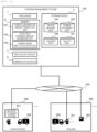
- Fig. 1 is a block diagram illustrating an example of a charging management system 100 according to a first embodiment of the present invention.
- the charging management system 100 is connected, via a network 400, to a delivery planning system 201 that manages delivery plans for logistics trucks at a logistics base 200 of a logistics company, a building 300 in which chargers for electric vehicles 202 are installed, chargers 301, and a power meter 302 that measures the total energy consumption of the building 300 in which the chargers are installed.
- a delivery planning system 201 that manages delivery plans for logistics trucks at a logistics base 200 of a logistics company, a building 300 in which chargers for electric vehicles 202 are installed, chargers 301, and a power meter 302 that measures the total energy consumption of the building 300 in which the chargers are installed.
- at least some of the logistics trucks used by the logistics company are electric vehicles 202.
- the charging management system 100 collects future delivery plans of the logistics company and the power efficiency of the electric vehicle 202 from the delivery planning system 201, collects a charging amount to the electric vehicle 202 from the charger 301, and collects the total power consumption of the building 300 in which the charger is installed from the power meter 302.
- Route delivery data 104 stores delivery plans collected from the logistics company.
- Power-efficiency data 105 stores information regarding the power efficiency of the electric vehicle 202 managed by the logistics base 200.
- Charger data 106 stores information regarding specification of the charger 301 installed in the building 300.
- Facility data 107 stores information regarding an electricity contract and the charging service of the building 300 in which the charger 301 is installed.
- the logistics base 200 and the building 300 may each be a plurality of business companies and a plurality of buildings. There may be a plurality of chargers 301 within the building 300.
- the charging management system 100 is a computer including a processor 1, a memory 2, a storage device 3, an input/output device 4, and a communication device 5.
- the processor 1 is a calculation device that executes programs stored in the memory 2. Some of the processing performed by the processor 1 by executing programs may be executed by another calculation device (for example, hardware such as ASIC or FPGA).
- the processor 1 operates as a functional unit that provides specific functions by executing processing according to a program of each functional unit. The same applies to other programs.
- the charging management system 100 is a computer and computer system that include functional units realized by the processor 1.
- the memory 2 includes ROM, which is a non-volatile storage element, and RAM, which is a volatile storage element.
- the ROM stores immutable programs (for example, BIOS) and the like.
- the RAM is a high-speed volatile storage element such as a dynamic random access memory (DRAM), and temporarily stores programs executed by the processor 1 and data used when the programs are executed. For example, a power consumption amount prediction unit 101, a total path charging amount estimation unit 102, and a power upper limit calculation unit 103 are loaded into the memory 2 as programs and executed by the processor 1.
- DRAM dynamic random access memory
- the storage device 3 is, for example, a large-capacity non-volatile storage device such as a magnetic storage device (HDD) or a flash memory (SSD).
- the storage device 3 stores data used by the processor 1 when executing a program (for example, the route delivery data 104, the charger data 106, the power-efficiency data 105, and the facility data 107), and the program executed by the processor 1.
- a program for example, the route delivery data 104, the charger data 106, the power-efficiency data 105, and the facility data 107
- the program is read from the storage device 3, loaded into the memory 2, and executed by the processor 1.
- the power consumption amount prediction unit 101 receives the charging amount from the charger 301 and the total energy consumption of the building 300 from the power meter 302, and predicts the power consumption amount in the building 300 for a 30-minute time frame including the current time. For example, when the current time is 9:10, the power consumption amount from 9:00 to 9:30 is predicted. When the current time is 9:33, the power consumption amount from 9:30 to 10:00 is predicted.
- a 30-minute time frame is illustrated as an example of a predetermined time frame, but the predetermined time period may be a time length other than 30 minutes (for example, 10 minutes or 1 hour).
- the total path charging amount estimation unit 102 receives route delivery data and information on the power efficiency of the electric vehicle 202 from the delivery planning system 201, and estimates the future total charging amount in the building 300 in which the charger 301 is installed.
- the total path charging amount estimation unit 102 receives route delivery data and information on the power efficiency of the electric vehicle 202 from each delivery planning system 201.
- the total path charging amount estimation unit 102 estimates the total charging amount by the chargers installed in each building.
- the power upper limit calculation unit 103 receives the future total charging amount of charging in the building 300 in which the charger 301 is installed from the total path charging amount estimation unit 102, receives the charging amount of the electric vehicle 202 from the charger 301, receives the power demand from the power meter 302 of the building 300 in which the charger 301 is installed, and calculates a power upper limit value of the building 300 that can ensure the economic viability of the charging service.
- the power upper limit calculation unit 103 calculates a power upper limit value for each building.
- the charging management system 100 may include the input/output device 4 as an input interface and an output interface.
- the input interface is an interface to which input devices such as a keyboard and a mouse (not illustrated) are connected and which receives input from an operator.
- the output interface is an interface to which an output device such as a display device or a printer (not illustrated) is connected and which outputs results of program execution in a format visible to the operator.
- Another device connected to the charging management system 100 via the network 400 may provide the input/output device.
- the program executed by the processor 1 is provided to the charging management system 100 from a removable medium (for example, a CD-ROM or a flash memory) or via the network 400, and is stored in the non-volatile storage device 3 which is a non-transitory storage medium. Therefore, the charging management system 100 may have an interface for reading data from the removable medium.
- a removable medium for example, a CD-ROM or a flash memory
- the charging management system 100 may have an interface for reading data from the removable medium.
- the charging management system 100 is a computer system configured on one physical computer or on a plurality of logically or physically configured computers, and may operate on a virtual computer configured on a plurality of physical computer resources. For example, subprograms configuring the total path charging amount estimation unit 102 may each operate on separate physical or logical computers, or a plurality of subprograms may be combined to operate on a single physical or logical computer.
- Fig. 2 is an explanatory diagram illustrating an example of a configuration of the route delivery data 104 according to the first embodiment of the present invention.
- the route delivery data 104 includes a route name 1031, a departure location 1032, a departure time 1033, an arrival location 1034, an arrival time 1035, and a traveling distance 1036 in one record.
- the route delivery data 104 stores data representing the delivery route collected from the delivery planning system 201.
- a route name 1021 is an identifier of the route.
- the departure location 1032 is an identifier representing the departure location of the logistics truck.
- the departure time 1033 is the time of departure from the departure location 1032.
- the arrival location 1034 is an identifier representing the arrival location of the logistics truck.
- the arrival time 1035 is the time of arrival at the arrival location 1034.
- the traveling distance 1036 is the traveling distance of the logistics truck from the departure location 1032 to the arrival location 1034.
- a logistics truck traveling a route A first leaves an own base A at 9:00, travels 15 km, and arrives at a customer building B at 10:00. Then, after staying at the customer building B for 15 minutes, the logistics truck leaves the customer building B at 10:15, travels 20 km, and arrives at a customer building C at 12:00. Then, after staying at the customer building C for 30 minutes, the logistics truck leaves the customer building C at 12:30, travels 10 km, and arrives at a distribution center at 13:00. Then, after staying at the distribution center for 60 minutes, the logistics truck leaves the distribution center at 14:00, travels 25 km, and arrives at the own base A at 16:00. That is, the route A is a route in which the logistics truck departs from the own base A at 9:00, passes through the customer building B, customer building C, and the distribution center, and returns to the own base A at 16:00.
- Fig. 3 is an explanatory diagram illustrating an example of a configuration of the power-efficiency data 105 according to the first embodiment of the present invention.
- the power-efficiency data 105 includes an electric vehicle ID 1041 and a power efficiency 1042 in one record.
- the power-efficiency data 105 stores data representing the power efficiency of the electric vehicle 202 traveling on the delivery route.
- the first record in Fig. 3 indicates that the power efficiency of the electric vehicle 202 identified by "EV truck A" among logistics trucks is 1.9 km/kWh (that is, the electric vehicle 202 travels 1.9 km per 1 kWh of power consumption amount).
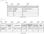
- Fig. 4 is an explanatory diagram illustrating an example of a configuration of the charger data 106 according to the first embodiment of the present invention.
- the charger data 106 includes a charger ID 1051, a charger output 1052, and a charger installation location 1053 in one record.
- the charger data 106 stores data representing the rated output value of the charger, the installation location of the charger, and the contracted power of the building in which the charger is installed.
- the charger ID 1051 is an identifier of the charger.
- the charger output 1052 is the rated output value of the installed charger.
- the charger installation location 1053 is an identifier representing the installation location of the charger.
- a charger A is installed in the customer building C and has a rated output of 100 kW.
- a charger B is installed at the own base and has a rated output of 6 kW.
- Fig. 5 is an explanatory diagram illustrating an example of a configuration of the facility data 107 according to the first embodiment of the present invention.
- the facility data 107 includes, in one record, a facility ID 1061, a contracted power 1062, a CO2 intensity 1063, a charging unit price 1064, a contracted power unit price 1065, a metered unit price 1066, and a target profit 1067.
- the facility data 107 stores information about the power contract of a facility (for example, the building 300), a target profit for installing a charger, and data about the charging price for a charger user.
- the facility ID 1061 is an identifier of the facility.
- the contracted power 1062 is an upper limit value of the power consumption that the facility has contracted with an electric power company.
- the CO2 intensity 1063 is a conversion coefficient for calculating a CO2 emission amount resulting from the power consumed by the facility.
- the charging unit price 1064 is a charging unit price charged to a user who uses the charger 301 installed at the facility.
- the contracted power unit price 1065 is a unit price per kW of power consumption that the facility has contracted with the electric power company.
- the metered unit price 1066 is a unit price per kWh of power consumption amount that the facility has contracted with the electric power company.
- the target profit 1067 is a target value of profit to be obtained by the charger 301 installed at the facility.
- Fig. 6 is a flowchart illustrating processing in the charging management system 100 according to the first embodiment of the present invention.
- the charging management system 100 periodically executes the processing illustrated in Fig. 6 to manage the charging amount by the charger 301.
- step S101 the power consumption amount prediction unit 101 predicts the power consumption amount of the building 300 for a 30-minute time frame including the current time. For example, when the current time is 9:10, the power consumption amount from 9:00 to 9:30 is predicted. When the current time is 9:33, the power consumption amount from 9:30 to 10:00 is predicted.
- the power consumption amount predicted here is the sum of the power consumption amount of the building 300 itself (that is, the facility only) for the 30-minute time frame and the power consumption amount for charging by the charger 301 installed in the building 300.
- step S102 the contracted power 1062 of the facility data 107 is referenced to determine whether the power consumption amount in the 30-minute time frame predicted in step S101 exceeds the contracted power of the building 300 in which the charger 301 is installed.
- the power consumption amount (kWh) in the 30-minute time frame is converted to power consumption (kW) for comparison with the contracted power.
- the process proceeds to step S103.
- the predicted power consumption amount does not exceed, the process ends.
- the total path charging amount estimation unit 102 estimates the total charging amount by the charger 301 installed in the building 300. Specifically, the total path charging amount estimation unit 102 uses the route delivery data 104 collected from the delivery planning system 201 to estimate the charging amount to be charged in the building 300 from a future delivery plan. For example, the total path charging amount estimation unit 102 estimates the total charging amount for the next few months.
- step S104 the power upper limit calculation unit 103 calculates a power upper limit value using the facility data 107 that stores the total charging amount estimated in step S103 and information related to the power contract of the building 300.
- step S105 it is determined whether the predicted value of power consumption of only the facility (building 300) excluding the power consumption of the charger 301 from the current time onward exceeds the power upper limit value. When the predicted value exceeds, the process proceeds to step S106. When the predicted value does not exceed, the process ends.
- step S106 the power supply by the charger 301 is stopped.
- the charging management system 100 stops the power supply by the charger 301 so that the power consumption in the building 300 does not exceed the power upper limit value calculated in step S104.
- step S107 when the power consumption during the 30-minute time frame exceeds the contracted power at the end of the 30-minute time frame, the charging management system 100 sets the power consumption as new contracted power and updates the value of the contracted power 1062.
- Fig. 7 is a flowchart illustrating a detail of processing of the power consumption amount prediction unit 101 according to the first embodiment of the present invention.
- the power consumption amount prediction unit 101 receives the charging power from the charger 301 and the total power consumption of the building from the power meter 302 as input, and outputs a predicted value of the power consumption amount for a 30-minute time frame.
- step S1011 the power consumption amount prediction unit 101 obtains the current charging power value from the charger 301 and the power consumption value of the building 300 from the power meter 302.
- step S1012 the power consumption amount prediction unit 101 calculates the accumulated power consumption amount at the current time in the 30-minute time frame.
- step S1013 the power consumption amount prediction unit 101 estimates the accumulated power amount at the end of the 30-minute time frame from the transition in the accumulated power consumption amount from the start of the 30-minute time frame to the current time and the charging power of the charger 301.
- the power consumption amount prediction unit 101 estimates the power consumption amount including the power consumption amount of charging by the charger 301, and the power consumption amount only of the facility excluding the power consumption amount of charging by the charger 301, respectively.
- Fig. 8 is an explanatory diagram illustrating an example of transition of the accumulated power consumption amount based on the power consumption collected from the charger 301 and the power meter 302 according to the first embodiment of the present invention.
- the power consumption amount prediction unit 101 periodically executes the process illustrated in Fig. 7 to manage the accumulated power consumption amount at the current time within a 30-minute time frame and the transition thereof as illustrated in Fig. 8 , and calculates a predicted value of the final accumulated power consumption amount within the 30-minute time frame.
- the example in Fig. 8 illustrates a status of the accumulated power consumption amount for the 30-minute time frame from 9:00 to 9:30.
- the power consumption amount prediction unit 101 estimates both the power consumption amount including the power consumption amount of the charger and the power consumption amount only of the facility excluding the power consumption amount of the charger for a period from the current time within the 30-minute time frame onwards.
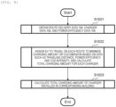
- Fig. 9 is a flowchart illustrating a detail of the processing of the total path charging amount estimation unit 102 according to the first embodiment of the present invention.
- the total path charging amount estimation unit 102 calculates the future total charging amount of the charger 301 installed in the building 300.
- step S1021 the total path charging amount estimation unit 102 acquires the route delivery data 104, the charger data 106, and the power-efficiency data 105.
- step S1022 the total path charging amount estimation unit 102 assigns EVs to travel on each route to minimize the charging amount or CO2 emission based on data such as the traveling distance, power efficiency, and CO2 intensity, and calculates the charging amount for each charger 301.
- step S1023 the total path charging amount estimation unit 102 calculates the total charging amount of the chargers 301 installed in the corresponding building 300.
- Fig. 10 is a flowchart illustrating a detail of the processing of the power upper limit calculation unit 103 in the first embodiment of the present invention.
- the power upper limit calculation unit 103 uses a charging amount x estimated by the total path charging amount estimation unit 102 to calculate an excess upper limit when the contracted power is exceeded.
- step S1031 the power upper limit calculation unit 103 acquires the facility data 107.
- the power upper limit calculation unit 103 uses the charging amount x for the future year estimated by the total path charging amount estimation unit 102, a value J of the metered unit price 1066 obtained from the facility data 107, a value C of the charging unit price 1064, a value R of the annual target profit 1067, and a value K of the contracted power unit price 1065 to calculate an excess upper limit value a of the contracted power using Formula 1.
- the accumulated power consumption amount for the 30-minute time frame exceeds the accumulated power consumption amount based on the current contracted power by continuing charging from the current time onward and the excess amount is a or more, the profit from the charging service will fall below the target profit 1067.
- [Math 1] a C ⁇ J x ⁇ R 12 K
- the above calculation is based on the assumption that the contracted power unit price K is determined based on the maximum power consumption for each month in the past year.
- the value of the contracted power 1062 is raised to a value based on the power consumption in that month, and the amount paid to a power provider based on the contracted power unit price K also increases.
- the contracted power 1062 for the following year is raised to match the power consumption at that time.
- One year is just an example of a predetermined period, and a period other than one year may be set depending on the contract with the power supplier.
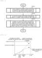
- Fig. 11 is an explanatory diagram illustrating an example of a comparison between the predicted power consumption amount and the power upper limit value in the first embodiment of the present invention.
- Fig. 11 illustrates an example of a case where the power consumption is predicted in a 30-minute time frame and the power upper limit value is finally exceeded in step S105. That is, the power consumption prediction for only the facility excluding the power consumption by the charger 301 after the current time reaches the power upper limit. That is, the prediction result shows that when charging by the charger 301 is continued after the current time, the power consumption amount for the 30-minute time frame will exceed the power upper limit, but when charging by the charger 301 is stopped at the current time, the power consumption amount for the 30-minute time frame will not exceed the power upper limit even if the facility consumes power for the remaining time.
- the final power consumption can be prevented from exceeding the power upper limit (that is, the current contracted power + a), and thereby preventing a deterioration in the profitability of the charging service.
- Fig. 12 is a block diagram illustrating an example of the charging management system 100 according to the second embodiment of the present invention.
- the charging management system 100 collects data regarding the power consumption of the charger 301 and the entire building 300 from the charger 301 and the power meter 302 via the energy management system 303.
- the charging management system 100 may obtain a predicted value of the power consumption amount from the energy management system 303.
- Steps S101 to S107 in Fig. 13 are the same as those illustrated in Fig. 6 , and therefore will not be described repeatedly.
- step S105 when it is determined in step S105 that a predicted value of power consumption of only the facility (building 300) excluding the power consumption of the charger 301 from the current time onward exceeds the power upper limit, step S108 is executed.
- step S108 the charging management system 100 presents the energy manager with the predicted value of power consumption when charging continues and the associated change in profit.
- the energy manager decides whether to stop the power supply by the charger 301 based on the change in profit. For example, the energy manager may determine not to stop the power supply by the charger 301 while it is determined based on the change in profit that the target profit can be secured by stopping the power supply by the charger 301 from the current time onwards, and may determine to stop the power supply by the charger 301 when it is determined that the target profit cannot be secured even when the power supply by the charger 301 from the current time onward is stopped (or before such a determination is made).
- step S106 is executed. On the other hand, when the energy manager determines not to stop the power supply by the charger 301, the process ends.
- a value b is obtained by subtracting the current contracted power from the power consumption based on a predicted value of the power consumption amount including that of the charger 301.
- R C ⁇ J x ⁇ 12 bK
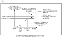
- Fig. 14 is an explanatory diagram illustrating an example of information presented to the energy manager by the charging management system 100 according to the third embodiment of the present invention.
- the charging management system 100 presents the energy manager with the expected profit when charging is stopped and the expected profit when charging is continued, and prompts the energy manager to decide whether to continue or stop charging. By quantitatively presenting the change in profit to the energy manager, it becomes possible for the energy manager to flexibly decide whether to continue charging.
- the system according to the embodiment of the present invention may be configured as follows, for example.
- the present invention is not limited to the above-described embodiments, and includes various modified examples.
- the above-described embodiments are described in detail to provide a better understanding of the present invention, and are not necessarily limited to those having all of the configurations described. It is also possible to replace part of the configuration of one embodiment with the configuration of another embodiment, and it is also possible to add the configuration of another embodiment to the configuration of one embodiment. It is also possible to add, delete, or replace part of the configuration of each embodiment with other configurations.
- the above-described configurations, functions, processing units, processing means, and the like may be realized in hardware, for example by designing some or all of the above-described configurations and the like as an integrated circuit.
- the above-described configurations, functions, and the like may be realized in software by a processor interpreting and executing a program that realizes each function.
- Information such as programs, tables, files, and the like that realize each function can be stored in storage devices such as a non-volatile semiconductor memory, a hard disk drive, and a solid state drive (SSDs), or in computer-readable non-transitory data storage media such as an IC card, an SD card, and DVD.
- control lines and information lines illustrated are those considered necessary for the description, and not all control lines and information lines in the product are necessarily illustrated. In reality, it can be considered that almost all components are interconnected.
Landscapes
- Business, Economics & Management (AREA)
- Engineering & Computer Science (AREA)
- Strategic Management (AREA)
- Economics (AREA)
- Development Economics (AREA)
- Human Resources & Organizations (AREA)
- Physics & Mathematics (AREA)
- Entrepreneurship & Innovation (AREA)
- Marketing (AREA)
- General Business, Economics & Management (AREA)
- General Physics & Mathematics (AREA)
- Theoretical Computer Science (AREA)
- Accounting & Taxation (AREA)
- Finance (AREA)
- Game Theory and Decision Science (AREA)
- Tourism & Hospitality (AREA)
- Health & Medical Sciences (AREA)
- Primary Health Care (AREA)
- General Health & Medical Sciences (AREA)
- Operations Research (AREA)
- Quality & Reliability (AREA)
- Data Mining & Analysis (AREA)
- Educational Administration (AREA)
- Public Health (AREA)
- Water Supply & Treatment (AREA)
- Charge And Discharge Circuits For Batteries Or The Like (AREA)
- Management, Administration, Business Operations System, And Electronic Commerce (AREA)
Abstract
Provided is a charging management system including a processor and a storage device, where the storage device holds delivery information including a delivery plan for an electric vehicle, power-efficiency information for the electric vehicle, facility information regarding facilities included in a delivery route for the electric vehicle, and charger information regarding a specification of a charger installed at the facility, the facility information includes a unit price of a power supplied to the facility, a charging price that is a unit price of a power provided by the charger installed at the facility, and a target value of profit obtained by providing power by the charger, and the processor estimates a charging amount by the charger for a predetermined future period based on the delivery information, the power-efficiency information, and the charger information, and calculates an upper limit of a power consumption amount of the facility in a predetermined time frame including a current time based on the estimated charging amount and the facility information so that the target value of the profit is ensured.
Description
- This application claims priority to
Japanese Patent Application No. 2022-114820, filed on July 19, 2022 - The present invention relates to a charging management system that manages power demand of a building and a charging amount of an electric vehicle, and calculates an appropriate upper limit of power consumption of the building.
-
JP2018-191471A PTL 1 describes a charging control method providing a charging control method for an electric vehicle that can efficiently and low-costly rapid charge a plurality of electric vehicles while suppressing power peaks due to rapid charging. - PTL 1:
JP2018-191471A - The technology described in
PTL 1 provides a charging control method for an electric vehicle that can efficiently and low-costly rapid charge a plurality of electric vehicles while suppressing power peaks due to rapid charging. However, with the technology described inPTL 1, contracted power corresponding to the power peak is fixed, so when an actual charging amount is greater than an assumed total charging amount at the time of design, it is not possible to improve convenience for an electric vehicle user by setting the power peak higher and increasing the charging amount for the electric vehicle. Conversely, when the actual charging amount is less than the assumed total charging amount, it is not possible to avoid a deterioration in profitability of a charging service by lowering the power peak. - The present invention is made in consideration of such problems, and an object thereof is to provide a system and method that predicts a future total charging amount of electric vehicles (EVs) of charger users when a power peak is expected to exceed an assumed value, calculates a power upper limit that ensures economic viability for a building that provides a charging environment, and controls a charging amount of the charger.
- A representative example of the invention disclosed in the present application is as follows. In other words, there is provided a charging management system including a processor and a storage device, where the storage device holds delivery information including a delivery plan for an electric vehicle, power-efficiency information for the electric vehicle, facility information regarding facilities included in a delivery route for the electric vehicle, and charger information regarding a specification of a charger installed at the facility for charging the electric vehicle, the facility information includes a unit price of a fee paid to a power supplier for power supplied to the facility, a charging price that is a unit price of a fee received from a charging power receiver for power provided by the charger installed at the facility to charge the electric vehicle, and a target value of profit obtained by providing power by the charger, and the processor estimates a charging amount by the charger for a predetermined future period based on the delivery information, the power-efficiency information, and the charger information, and calculates an upper limit of a power consumption amount of the facility in a predetermined time frame including a current time based on the estimated charging amount and the facility information so that the target value of the profit is ensured.
- According to one aspect of the present invention, a building owner who provides a charging service can improve convenience of a user who charges an electric vehicle while ensuring profitability of the service. Problems, configurations, and effects other than those described above will be made clear through the description of the following embodiments.
-
- [
Fig. 1] Fig. 1 is a block diagram illustrating an example of a charging management system according to a first embodiment of the present invention. - [
Fig. 2] Fig. 2 is an explanatory diagram illustrating an example of a configuration of route delivery data according to the first embodiment of the present invention. - [
Fig. 3] Fig. 3 is an explanatory diagram illustrating an example of a configuration of power-efficiency data according to the first embodiment of the present invention. - [
Fig. 4] Fig. 4 is an explanatory diagram illustrating an example of a configuration of charger data according to the first embodiment of the present invention. - [
Fig. 5] Fig. 5 is an explanatory diagram illustrating an example of a configuration of facility data according to the first embodiment of the present invention. - [
Fig. 6] Fig. 6 is a flowchart illustrating processing in the charging management system according to the first embodiment of the present invention. - [
Fig. 7] Fig. 7 is a flowchart illustrating a detail of processing by a power consumption amount prediction unit according to the first embodiment of the present invention. - [
Fig. 8] Fig. 8 is an explanatory diagram illustrating an example of transition of accumulated power consumption amount based on power consumption collected from a charger and a power meter according to the first embodiment of the present invention. - [
Fig. 9] Fig. 9 is a flowchart illustrating a detail of processing by a total path charging amount estimation unit according to the first embodiment of the present invention. - [
Fig. 10] Fig. 10 is a flowchart illustrating a detail of processing by a power upper limit calculation unit according to the first embodiment of the present invention. - [
Fig. 11] Fig. 11 is an explanatory diagram illustrating an example of a comparison between a predicted power consumption amount and a power upper limit value in the first embodiment of the present invention. - [
Fig. 12] Fig. 12 is a block diagram illustrating an example of a charging management system according to a second embodiment of the present invention. - [
Fig. 13] Fig. 13 is a flowchart illustrating processing in a charging management system according to a third embodiment of the present invention. - [
Fig. 14] Fig. 14 is an explanatory diagram illustrating an example of information presented to an energy manager by the charging management system according to the third embodiment of the present invention. - Hereinafter, an embodiment of the present invention will be described with reference to the drawings.
- In the present embodiment, an example of a charging management system that can provide a charging service without losing economic viability of the charging service by receiving a delivery plan from a logistics company, estimating a future charging amount at a delivery destination building, and calculating an appropriate power upper limit value will be described.
-
Fig. 1 is a block diagram illustrating an example of acharging management system 100 according to a first embodiment of the present invention. - The
charging management system 100 is connected, via anetwork 400, to adelivery planning system 201 that manages delivery plans for logistics trucks at alogistics base 200 of a logistics company, abuilding 300 in which chargers forelectric vehicles 202 are installed,chargers 301, and apower meter 302 that measures the total energy consumption of thebuilding 300 in which the chargers are installed. In the present embodiment, at least some of the logistics trucks used by the logistics company areelectric vehicles 202. - The
charging management system 100 collects future delivery plans of the logistics company and the power efficiency of theelectric vehicle 202 from thedelivery planning system 201, collects a charging amount to theelectric vehicle 202 from thecharger 301, and collects the total power consumption of thebuilding 300 in which the charger is installed from thepower meter 302. -
Route delivery data 104 stores delivery plans collected from the logistics company. Power-efficiency data 105 stores information regarding the power efficiency of theelectric vehicle 202 managed by thelogistics base 200.Charger data 106 stores information regarding specification of thecharger 301 installed in thebuilding 300.Facility data 107 stores information regarding an electricity contract and the charging service of thebuilding 300 in which thecharger 301 is installed. Thelogistics base 200 and thebuilding 300 may each be a plurality of business companies and a plurality of buildings. There may be a plurality ofchargers 301 within thebuilding 300. - The
charging management system 100 is a computer including aprocessor 1, amemory 2, astorage device 3, an input/output device 4, and acommunication device 5. - The
processor 1 is a calculation device that executes programs stored in thememory 2. Some of the processing performed by theprocessor 1 by executing programs may be executed by another calculation device (for example, hardware such as ASIC or FPGA). Theprocessor 1 operates as a functional unit that provides specific functions by executing processing according to a program of each functional unit. The same applies to other programs. Thecharging management system 100 is a computer and computer system that include functional units realized by theprocessor 1. - The
memory 2 includes ROM, which is a non-volatile storage element, and RAM, which is a volatile storage element. The ROM stores immutable programs (for example, BIOS) and the like. The RAM is a high-speed volatile storage element such as a dynamic random access memory (DRAM), and temporarily stores programs executed by theprocessor 1 and data used when the programs are executed. For example, a power consumptionamount prediction unit 101, a total path chargingamount estimation unit 102, and a power upperlimit calculation unit 103 are loaded into thememory 2 as programs and executed by theprocessor 1. - The
storage device 3 is, for example, a large-capacity non-volatile storage device such as a magnetic storage device (HDD) or a flash memory (SSD). Thestorage device 3 stores data used by theprocessor 1 when executing a program (for example, theroute delivery data 104, thecharger data 106, the power-efficiency data 105, and the facility data 107), and the program executed by theprocessor 1. In other words, the program is read from thestorage device 3, loaded into thememory 2, and executed by theprocessor 1. - The power consumption amount
prediction unit 101 receives the charging amount from thecharger 301 and the total energy consumption of thebuilding 300 from thepower meter 302, and predicts the power consumption amount in thebuilding 300 for a 30-minute time frame including the current time. For example, when the current time is 9:10, the power consumption amount from 9:00 to 9:30 is predicted. When the current time is 9:33, the power consumption amount from 9:30 to 10:00 is predicted. - In the present embodiment, a 30-minute time frame is illustrated as an example of a predetermined time frame, but the predetermined time period may be a time length other than 30 minutes (for example, 10 minutes or 1 hour).
- The total path charging
amount estimation unit 102 receives route delivery data and information on the power efficiency of theelectric vehicle 202 from thedelivery planning system 201, and estimates the future total charging amount in thebuilding 300 in which thecharger 301 is installed. When there are a plurality oflogistics bases 200 and a plurality ofdelivery planning systems 201, the total path chargingamount estimation unit 102 receives route delivery data and information on the power efficiency of theelectric vehicle 202 from eachdelivery planning system 201. When there are a plurality ofbuildings 300, the total path chargingamount estimation unit 102 estimates the total charging amount by the chargers installed in each building. - The power upper
limit calculation unit 103 receives the future total charging amount of charging in thebuilding 300 in which thecharger 301 is installed from the total path chargingamount estimation unit 102, receives the charging amount of theelectric vehicle 202 from thecharger 301, receives the power demand from thepower meter 302 of thebuilding 300 in which thecharger 301 is installed, and calculates a power upper limit value of thebuilding 300 that can ensure the economic viability of the charging service. When there are a plurality ofbuildings 300, the power upperlimit calculation unit 103 calculates a power upper limit value for each building. - The
charging management system 100 may include the input/output device 4 as an input interface and an output interface. The input interface is an interface to which input devices such as a keyboard and a mouse (not illustrated) are connected and which receives input from an operator. The output interface is an interface to which an output device such as a display device or a printer (not illustrated) is connected and which outputs results of program execution in a format visible to the operator. Another device connected to thecharging management system 100 via thenetwork 400 may provide the input/output device. - The program executed by the
processor 1 is provided to thecharging management system 100 from a removable medium (for example, a CD-ROM or a flash memory) or via thenetwork 400, and is stored in thenon-volatile storage device 3 which is a non-transitory storage medium. Therefore, thecharging management system 100 may have an interface for reading data from the removable medium. - The
charging management system 100 is a computer system configured on one physical computer or on a plurality of logically or physically configured computers, and may operate on a virtual computer configured on a plurality of physical computer resources. For example, subprograms configuring the total path chargingamount estimation unit 102 may each operate on separate physical or logical computers, or a plurality of subprograms may be combined to operate on a single physical or logical computer. -
Fig. 2 is an explanatory diagram illustrating an example of a configuration of theroute delivery data 104 according to the first embodiment of the present invention. - The
route delivery data 104 includes aroute name 1031, adeparture location 1032, adeparture time 1033, anarrival location 1034, anarrival time 1035, and atraveling distance 1036 in one record. Theroute delivery data 104 stores data representing the delivery route collected from thedelivery planning system 201. - A route name 1021 is an identifier of the route. The
departure location 1032 is an identifier representing the departure location of the logistics truck. Thedeparture time 1033 is the time of departure from thedeparture location 1032. Thearrival location 1034 is an identifier representing the arrival location of the logistics truck. Thearrival time 1035 is the time of arrival at thearrival location 1034. Thetraveling distance 1036 is the traveling distance of the logistics truck from thedeparture location 1032 to thearrival location 1034. - For example, according to the first four records in
Fig. 2 , a logistics truck traveling a route A first leaves an own base A at 9:00, travels 15 km, and arrives at a customer building B at 10:00. Then, after staying at the customer building B for 15 minutes, the logistics truck leaves the customer building B at 10:15, travels 20 km, and arrives at a customer building C at 12:00. Then, after staying at the customer building C for 30 minutes, the logistics truck leaves the customer building C at 12:30, travels 10 km, and arrives at a distribution center at 13:00. Then, after staying at the distribution center for 60 minutes, the logistics truck leaves the distribution center at 14:00, travels 25 km, and arrives at the own base A at 16:00. That is, the route A is a route in which the logistics truck departs from the own base A at 9:00, passes through the customer building B, customer building C, and the distribution center, and returns to the own base A at 16:00. -
Fig. 3 is an explanatory diagram illustrating an example of a configuration of the power-efficiency data 105 according to the first embodiment of the present invention. - The power-
efficiency data 105 includes anelectric vehicle ID 1041 and apower efficiency 1042 in one record. The power-efficiency data 105 stores data representing the power efficiency of theelectric vehicle 202 traveling on the delivery route. - For example, the first record in
Fig. 3 indicates that the power efficiency of theelectric vehicle 202 identified by "EV truck A" among logistics trucks is 1.9 km/kWh (that is, theelectric vehicle 202 travels 1.9 km per 1 kWh of power consumption amount). -
Fig. 4 is an explanatory diagram illustrating an example of a configuration of thecharger data 106 according to the first embodiment of the present invention. - The
charger data 106 includes acharger ID 1051, acharger output 1052, and acharger installation location 1053 in one record. Thecharger data 106 stores data representing the rated output value of the charger, the installation location of the charger, and the contracted power of the building in which the charger is installed. Thecharger ID 1051 is an identifier of the charger. Thecharger output 1052 is the rated output value of the installed charger. Thecharger installation location 1053 is an identifier representing the installation location of the charger. - In the example of
Fig. 4 , a charger A is installed in the customer building C and has a rated output of 100 kW. A charger B is installed at the own base and has a rated output of 6 kW. -
Fig. 5 is an explanatory diagram illustrating an example of a configuration of thefacility data 107 according to the first embodiment of the present invention. - The
facility data 107 includes, in one record, afacility ID 1061, a contractedpower 1062, aCO2 intensity 1063, a chargingunit price 1064, a contractedpower unit price 1065, ametered unit price 1066, and atarget profit 1067. Thefacility data 107 stores information about the power contract of a facility (for example, the building 300), a target profit for installing a charger, and data about the charging price for a charger user. - The
facility ID 1061 is an identifier of the facility. The contractedpower 1062 is an upper limit value of the power consumption that the facility has contracted with an electric power company. TheCO2 intensity 1063 is a conversion coefficient for calculating a CO2 emission amount resulting from the power consumed by the facility. The chargingunit price 1064 is a charging unit price charged to a user who uses thecharger 301 installed at the facility. The contractedpower unit price 1065 is a unit price per kW of power consumption that the facility has contracted with the electric power company. Themetered unit price 1066 is a unit price per kWh of power consumption amount that the facility has contracted with the electric power company. Thetarget profit 1067 is a target value of profit to be obtained by thecharger 301 installed at the facility. -
Fig. 6 is a flowchart illustrating processing in thecharging management system 100 according to the first embodiment of the present invention. Thecharging management system 100 periodically executes the processing illustrated inFig. 6 to manage the charging amount by thecharger 301. - In step S101, the power consumption
amount prediction unit 101 predicts the power consumption amount of thebuilding 300 for a 30-minute time frame including the current time. For example, when the current time is 9:10, the power consumption amount from 9:00 to 9:30 is predicted. When the current time is 9:33, the power consumption amount from 9:30 to 10:00 is predicted. The power consumption amount predicted here is the sum of the power consumption amount of thebuilding 300 itself (that is, the facility only) for the 30-minute time frame and the power consumption amount for charging by thecharger 301 installed in thebuilding 300. - In step S102, the contracted
power 1062 of thefacility data 107 is referenced to determine whether the power consumption amount in the 30-minute time frame predicted in step S101 exceeds the contracted power of thebuilding 300 in which thecharger 301 is installed. Here, the power consumption amount (kWh) in the 30-minute time frame is converted to power consumption (kW) for comparison with the contracted power. For example, when the power consumption amount in the 30-minute time frame predicted in step S101 is 10 kWh, 10 kWh / (30 minutes / 60 minutes) = 20 kW is compared with the contracted power. When the predicted power consumption amount exceeds, the process proceeds to step S103. When the predicted power consumption amount does not exceed, the process ends. When the predicted power consumption amount does not exceed the contracted power, the basic charge for electricity will not increase, so it can be said that there is no impact on the assumed balance. When the predicted power consumption amount exceeds, the contracted power charge will increase, which may worsen the profitability of the charging service. Therefore, to ensure the target profit, it is necessary to calculate an allowable upper limit value and control the charging amount so that the upper limit value is not exceeded. - In step S103, the total path charging
amount estimation unit 102 estimates the total charging amount by thecharger 301 installed in thebuilding 300. Specifically, the total path chargingamount estimation unit 102 uses theroute delivery data 104 collected from thedelivery planning system 201 to estimate the charging amount to be charged in thebuilding 300 from a future delivery plan. For example, the total path chargingamount estimation unit 102 estimates the total charging amount for the next few months. - In step S104, the power upper
limit calculation unit 103 calculates a power upper limit value using thefacility data 107 that stores the total charging amount estimated in step S103 and information related to the power contract of thebuilding 300. - In step S105, it is determined whether the predicted value of power consumption of only the facility (building 300) excluding the power consumption of the
charger 301 from the current time onward exceeds the power upper limit value. When the predicted value exceeds, the process proceeds to step S106. When the predicted value does not exceed, the process ends. - In step S106, the power supply by the
charger 301 is stopped. In other words, thecharging management system 100 stops the power supply by thecharger 301 so that the power consumption in thebuilding 300 does not exceed the power upper limit value calculated in step S104. - In step S107, when the power consumption during the 30-minute time frame exceeds the contracted power at the end of the 30-minute time frame, the
charging management system 100 sets the power consumption as new contracted power and updates the value of the contractedpower 1062. -
Fig. 7 is a flowchart illustrating a detail of processing of the power consumptionamount prediction unit 101 according to the first embodiment of the present invention. The power consumptionamount prediction unit 101 receives the charging power from thecharger 301 and the total power consumption of the building from thepower meter 302 as input, and outputs a predicted value of the power consumption amount for a 30-minute time frame. - In step S1011, the power consumption
amount prediction unit 101 obtains the current charging power value from thecharger 301 and the power consumption value of thebuilding 300 from thepower meter 302. - In step S1012, the power consumption
amount prediction unit 101 calculates the accumulated power consumption amount at the current time in the 30-minute time frame. - In step S1013, the power consumption
amount prediction unit 101 estimates the accumulated power amount at the end of the 30-minute time frame from the transition in the accumulated power consumption amount from the start of the 30-minute time frame to the current time and the charging power of thecharger 301. Here, the power consumptionamount prediction unit 101 estimates the power consumption amount including the power consumption amount of charging by thecharger 301, and the power consumption amount only of the facility excluding the power consumption amount of charging by thecharger 301, respectively. -
Fig. 8 is an explanatory diagram illustrating an example of transition of the accumulated power consumption amount based on the power consumption collected from thecharger 301 and thepower meter 302 according to the first embodiment of the present invention. - The power consumption
amount prediction unit 101 periodically executes the process illustrated inFig. 7 to manage the accumulated power consumption amount at the current time within a 30-minute time frame and the transition thereof as illustrated inFig. 8 , and calculates a predicted value of the final accumulated power consumption amount within the 30-minute time frame. The example inFig. 8 illustrates a status of the accumulated power consumption amount for the 30-minute time frame from 9:00 to 9:30. Here, the power consumptionamount prediction unit 101 estimates both the power consumption amount including the power consumption amount of the charger and the power consumption amount only of the facility excluding the power consumption amount of the charger for a period from the current time within the 30-minute time frame onwards. -
Fig. 9 is a flowchart illustrating a detail of the processing of the total path chargingamount estimation unit 102 according to the first embodiment of the present invention. The total path chargingamount estimation unit 102 calculates the future total charging amount of thecharger 301 installed in thebuilding 300. - In step S1021, the total path charging
amount estimation unit 102 acquires theroute delivery data 104, thecharger data 106, and the power-efficiency data 105. - In step S1022, the total path charging
amount estimation unit 102 assigns EVs to travel on each route to minimize the charging amount or CO2 emission based on data such as the traveling distance, power efficiency, and CO2 intensity, and calculates the charging amount for eachcharger 301. - In step S1023, the total path charging
amount estimation unit 102 calculates the total charging amount of thechargers 301 installed in the correspondingbuilding 300. -
Fig. 10 is a flowchart illustrating a detail of the processing of the power upperlimit calculation unit 103 in the first embodiment of the present invention. The power upperlimit calculation unit 103 uses a charging amount x estimated by the total path chargingamount estimation unit 102 to calculate an excess upper limit when the contracted power is exceeded. - In step S1031, the power upper
limit calculation unit 103 acquires thefacility data 107. - In step S1032, the power upper
limit calculation unit 103 uses the charging amount x for the future year estimated by the total path chargingamount estimation unit 102, a value J of the meteredunit price 1066 obtained from thefacility data 107, a value C of the chargingunit price 1064, a value R of theannual target profit 1067, and a value K of the contractedpower unit price 1065 to calculate an excess upper limit value a of the contractedpower using Formula 1. When the accumulated power consumption amount for the 30-minute time frame exceeds the accumulated power consumption amount based on the current contracted power by continuing charging from the current time onward and the excess amount is a or more, the profit from the charging service will fall below thetarget profit 1067.
[Math 1]
- The above calculation is based on the assumption that the contracted power unit price K is determined based on the maximum power consumption for each month in the past year. In other words, when the power consumption in a certain month exceeds the value of the contracted
power 1062 at that time, for the following year, even when the actual power consumption is low, the value of the contractedpower 1062 is raised to a value based on the power consumption in that month, and the amount paid to a power provider based on the contracted power unit price K also increases. When there is a month in which the power consumption is even higher in that year, the contractedpower 1062 for the following year is raised to match the power consumption at that time. One year is just an example of a predetermined period, and a period other than one year may be set depending on the contract with the power supplier. - Even when the power consumption in a certain month exceeds the contracted power at that time and results in an increase in the amount paid to the power provider for the following year, if the charging amount x over the following year is large, the profit based on a difference between the charging price C and the metered unit price J will be large, and as a result, it may be possible to secure the target
profit R. Formula 1 described above is used to calculate the upper limit of the excess of the accumulated power consumption amount that can ensure the target profit R, based on the future charging amount x estimated at the current time. The larger the estimated future charging amount x, and the greater the difference between the charging price C and the metered unit price J, the higher the upper limit of the excess of the accumulated power consumption amount. -
Fig. 11 is an explanatory diagram illustrating an example of a comparison between the predicted power consumption amount and the power upper limit value in the first embodiment of the present invention. - Specifically,
Fig. 11 illustrates an example of a case where the power consumption is predicted in a 30-minute time frame and the power upper limit value is finally exceeded in step S105. That is, the power consumption prediction for only the facility excluding the power consumption by thecharger 301 after the current time reaches the power upper limit. That is, the prediction result shows that when charging by thecharger 301 is continued after the current time, the power consumption amount for the 30-minute time frame will exceed the power upper limit, but when charging by thecharger 301 is stopped at the current time, the power consumption amount for the 30-minute time frame will not exceed the power upper limit even if the facility consumes power for the remaining time. By expecting the power consumption of the facility that cannot stop consuming power and determining that the power upper limit will be exceeded and stopping charging by thecharger 301, the final power consumption can be prevented from exceeding the power upper limit (that is, the current contracted power + a), and thereby preventing a deterioration in the profitability of the charging service. - Conversely, when the predicted power consumption including the power consumption of the
charger 301 does not exceed the power upper limit (current contracted power + a), there is no risk of damaging the profitability of the charging service even when charging is performed exceeding the contracted power. Even when the contracted power is exceeded, a user of theelectric vehicle 202 who uses the charging service can charge as much as is necessary for driving as long as the power upper limit for ensuring profitability is not exceeded, which leads to improved convenience of theelectric vehicle 202. To maximize the convenience of theelectric vehicle 202 while ensuring a predetermined profitability, it is desirable to stop charging by thecharger 301 at the latest time within a range where the predicted power consumption only at the facility excluding the power consumption by thecharger 301 from the current time onward does not exceed the power upper limit. - In a second embodiment, a case where an energy management system is installed in the
building 300 will be described. In the second embodiment, configurations different from those in the first embodiment will be described, and descriptions of configurations that are the same as those in the first embodiment will be omitted. -
Fig. 12 is a block diagram illustrating an example of thecharging management system 100 according to the second embodiment of the present invention. - When an
energy management system 303 is installed in thebuilding 300 as illustrated inFig. 12 , thecharging management system 100 collects data regarding the power consumption of thecharger 301 and theentire building 300 from thecharger 301 and thepower meter 302 via theenergy management system 303. - Furthermore, when the
energy management system 303 has a function equivalent to the function of the power consumptionamount prediction unit 101, thecharging management system 100 may obtain a predicted value of the power consumption amount from theenergy management system 303. - In a third embodiment, a case where an impact on profit by continuing charging by the
charger 301 from the current time onward is presented to an energy manager of the building, and decision to stop the power supply by thecharger 301 is left to the energy manager will be described. In the third embodiment, configurations different from those in the embodiment described above will be described, and descriptions of configurations that are the same as those in the first embodiment will be omitted. -
Fig. 13 is a flowchart illustrating processing in thecharging management system 100 of the third embodiment of the present invention. In the processing, an impact on profit by continuing charging by thecharger 301 from the current time onward, specifically, whether the power consumption amount will exceed the power upper limit by continuing charging by thecharger 301 after the current time, and whether the target profit will be secured, are presented to the energy manager. - Steps S101 to S107 in
Fig. 13 are the same as those illustrated inFig. 6 , and therefore will not be described repeatedly. In the processing ofFig. 13 , when it is determined in step S105 that a predicted value of power consumption of only the facility (building 300) excluding the power consumption of thecharger 301 from the current time onward exceeds the power upper limit, step S108 is executed. In step S108, thecharging management system 100 presents the energy manager with the predicted value of power consumption when charging continues and the associated change in profit. - The energy manager decides whether to stop the power supply by the
charger 301 based on the change in profit. For example, the energy manager may determine not to stop the power supply by thecharger 301 while it is determined based on the change in profit that the target profit can be secured by stopping the power supply by thecharger 301 from the current time onwards, and may determine to stop the power supply by thecharger 301 when it is determined that the target profit cannot be secured even when the power supply by thecharger 301 from the current time onward is stopped (or before such a determination is made). To maximize the convenience of theelectric vehicle 202 while securing a predetermined profitability, it is desirable to determine to stop the power supply by thecharger 301 at the latest time within a range in which the predicted power consumption of only the facility excluding the power consumption by thecharger 301 from the current time onward does not exceed the power upper limit. - When the energy manager determines to stop the power supply by the
charger 301, step S106 is executed. On the other hand, when the energy manager determines not to stop the power supply by thecharger 301, the process ends. - The profit when charging continues is calculated using
Formula 2. A value b is obtained by subtracting the current contracted power from the power consumption based on a predicted value of the power consumption amount including that of thecharger 301.
[Math 2]
-
Fig. 14 is an explanatory diagram illustrating an example of information presented to the energy manager by thecharging management system 100 according to the third embodiment of the present invention. - The
charging management system 100 presents the energy manager with the expected profit when charging is stopped and the expected profit when charging is continued, and prompts the energy manager to decide whether to continue or stop charging. By quantitatively presenting the change in profit to the energy manager, it becomes possible for the energy manager to flexibly decide whether to continue charging. - The system according to the embodiment of the present invention may be configured as follows, for example.
-
- (1) A charging management system (for example, the charging management system 100) including a processor (for example, the processor 1) and a storage device (for example, the memory 2 and the storage device 3), where the storage device holds delivery information (for example, the route delivery data 104) including a delivery plan for an electric vehicle (for example, the electric vehicle 202), power-efficiency information (for example, the power-efficiency data 105) for the electric vehicle, facility information (for example, the facility data 107) regarding facilities (for example, the building 300) included in a delivery route for the electric vehicle, and charger information (for example, the charger data 106) regarding a specification of a charger (for example, the charger 301) installed at the facility for charging the electric vehicle, the facility information includes a unit price (for example, the contracted power unit price 1065 and the metered unit price 1066) of a fee paid to a power supplier for power supplied to the facility, a charging price (for example, the charging unit price 1064) that is a unit price of a fee received from a charging power receiver for power provided by the charger installed at the facility to charge the electric vehicle, and a target value (for example, the target profit 1067) of profit obtained by providing power by the charger, and the processor estimates a charging amount by the charger for a predetermined future period based on the delivery information, the power-efficiency information, and the charger information (for example, step S103), and calculates an upper limit of a power consumption amount of the facility in a predetermined time frame (for example, the accumulated power consumption amount for a 30-minute time frame) including a current time based on the estimated charging amount and the facility information so that the target value of the profit is ensured (for example, step S104).
Accordingly, a building owner who provides a charging service can ensure the profitability of the service while improving convenience for a user who charges their electric vehicle. - (2) In (1) described above, the facility information includes contracted power (for example, the contracted power 1062) between the facility and the power supplier, and the processor predicts the power consumption amount of the facility including a power consumption amount of the charger for the predetermined time frame (for example, step S101), and estimates the charging amount and calculates an upper limit of the power consumption amount when (for example, when Yes in step S102) power consumption based on the predicted power consumption amount exceeds the contracted power.
Accordingly, the building owner who provides the charging service can ensure the profitability of the service even when the contracted power is expected to be exceeded, while improving the convenience of a user who charges their electric vehicle. - (3) In (2) described above, the processor controls the charger to stop charging when it is determined that the power consumption amount of the facility in the predetermined time frame exceeds the upper limit even when charging by the charger from the current time onward is stopped (for example, step S106 when the answer is Yes in step S105 in
Fig. 5 ).
Accordingly, a decline in the profitability of the service can be prevented. - (4) In (2) described above, the processor calculates and outputs an amount of profit obtained by providing power by the charger in each case of when the charger stops charging from the current time onward and when the charger does not stop charging (for example, step S108 in
Fig. 13 ), and when information instructing that charging by the charger be stopped is input, the charger is controlled to stop charging (for example, step S106 when the answer is "Stop" in step S108 inFig. 13 ).
Accordingly, the user can flexibly determine whether to continue charging while being presented with information about the profitability of the service. - (5) In (2) described above, the unit price of the fee paid to the power supplier for the power supplied to the facility includes a metered unit price (for example, the metered unit price 1066) for determining a fee according to a power consumption amount of the facility, and a contracted power unit price (for example, the contracted power unit price 1065) for determining a fee according to the contracted power, and the processor calculates an amount of profit obtained by providing power by the charger so that the profit increases as a difference between the metered unit price and the charging price multiplied by the estimated charging amount increases, and the profit decreases as the contracted power unit price increases (for example, Formula 1).
- Accordingly, it is possible to appropriately calculate the upper limit of power consumption amount that does not impair the profitability of the service.
- The present invention is not limited to the above-described embodiments, and includes various modified examples. For example, the above-described embodiments are described in detail to provide a better understanding of the present invention, and are not necessarily limited to those having all of the configurations described. It is also possible to replace part of the configuration of one embodiment with the configuration of another embodiment, and it is also possible to add the configuration of another embodiment to the configuration of one embodiment. It is also possible to add, delete, or replace part of the configuration of each embodiment with other configurations.
- Furthermore, the above-described configurations, functions, processing units, processing means, and the like may be realized in hardware, for example by designing some or all of the above-described configurations and the like as an integrated circuit. The above-described configurations, functions, and the like may be realized in software by a processor interpreting and executing a program that realizes each function. Information such as programs, tables, files, and the like that realize each function can be stored in storage devices such as a non-volatile semiconductor memory, a hard disk drive, and a solid state drive (SSDs), or in computer-readable non-transitory data storage media such as an IC card, an SD card, and DVD.
- In addition, the control lines and information lines illustrated are those considered necessary for the description, and not all control lines and information lines in the product are necessarily illustrated. In reality, it can be considered that almost all components are interconnected.
Claims (10)
- A charging management system comprising:a processor and a storage device, whereinthe storage device holds delivery information including a delivery plan for an electric vehicle, power-efficiency information for the electric vehicle, facility information regarding facilities included in a delivery route for the electric vehicle, and charger information regarding a specification of a charger installed at the facility for charging the electric vehicle,the facility information includes a unit price of a fee paid to a power supplier for power supplied to the facility, a charging price that is a unit price of a fee received from a charging power receiver for power provided by the charger installed at the facility to charge the electric vehicle, and a target value of profit obtained by providing power by the charger, andthe processorestimates a charging amount by the charger for a predetermined future period based on the delivery information, the power-efficiency information, and the charger information, andcalculates an upper limit of a power consumption amount of the facility in a predetermined time frame including a current time based on the estimated charging amount and the facility information so that the target value of the profit is ensured.
- The charging management system according to Claim 1, whereinthe facility information includes contracted power between the facility and the power supplier, andthe processorpredicts the power consumption amount of the facility including a power consumption amount of the charger for the predetermined time frame, andestimates the charging amount and calculates an upper limit of the power consumption amount when power consumption based on the predicted power consumption amount exceeds the contracted power.
- The charging management system according to Claim 2, wherein
the processor controls the charger to stop charging when it is determined that the power consumption amount of the facility in the predetermined time frame exceeds the upper limit even when charging by the charger from the current time onward is stopped. - The charging management system according to Claim 2, whereinthe processor calculates and outputs an amount of profit obtained by providing power by the charger in each case of when the charger stops charging from the current time onward and when the charger does not stop charging, andwhen information instructing that charging by the charger be stopped is input, the charger is controlled to stop charging.
- The charging management system according to Claim 2, whereinthe unit price of the fee paid to the power supplier for the power supplied to the facility includes a metered unit price for determining a fee according to the power consumption amount of the facility, and a contracted power unit price for determining a fee according to the contracted power, andthe processor calculates an amount of profit obtained by providing power by the charger so that the profit increases as a difference between the metered unit price and the charging price multiplied by the estimated charging amount increases, and the profit decreases as the contracted power unit price increases.
- A charging management method executed by a charging management system, whereinthe charging management system includes a processor and a storage device,the storage device holds delivery information including a delivery plan for an electric vehicle, power-efficiency information for the electric vehicle, facility information regarding facilities included in a delivery route for the electric vehicle, and charger information regarding a specification of a charger installed at the facility for charging the electric vehicle,the facility information includes a unit price of a fee paid to a power supplier for power supplied to the facility, a charging price that is a unit price of a fee received from a charging power receiver for power provided by the charger installed at the facility to charge the electric vehicle, and a target value of profit obtained by providing power by the charger, andthe charging management method includesa first step in which the processor estimates a charging amount by the charger for a predetermined future period based on the delivery information, the power-efficiency information, and the charger information, anda second step in which the processor calculates an upper limit of a power consumption amount of the facility in a predetermined time frame including a current time based on the estimated charging amount and the facility information so that the target value of the profit is ensured.
- The charging management method according to Claim 6, whereinthe facility information includes contracted power between the facility and the power supplier,the charging management method further includes a step of in which the processor predicts the power consumption amount of the facility including a power consumption amount of the charger for the predetermined time frame, andthe processor executes the first step and the second step when power consumption based on the predicted power consumption amount exceeds the contracted power.
- The charging management method according to Claim 7, further comprising:
a step in which the processor controls the charger to stop charging when the processor determines that the power consumption amount of the facility in the predetermined time frame exceeds the upper limit even when charging by the charger from the current time onward is stopped. - The charging management method according to Claim 7, further comprising:a step in which the processor calculates and outputs an amount of profit obtained by providing power by the charger in each case of when the charger stops charging from the current time onward and when the charger does not stop charging; anda step in which, when information instructing that charging by the charger be stopped is input, the processor controls the charger to stop charging.
- The charging management method according to Claim 7, whereinthe unit price of the fee paid to the power supplier for the power supplied to the facility includes a metered unit price for determining a fee according to the power consumption amount of the facility, and a contracted power unit price for determining a fee according to the contracted power, andin the second step, the processor calculates an amount of profit obtained by providing power by the charger so that the profit increases as a difference between the metered unit price and the charging price multiplied by the estimated charging amount increases, and the profit decreases as the contracted power unit price increases.
Applications Claiming Priority (2)
| Application Number | Priority Date | Filing Date | Title |
|---|---|---|---|
| JP2022114820A JP2024012958A (en) | 2022-07-19 | 2022-07-19 | Charging management system and charging management method |
| PCT/JP2023/007576 WO2024018675A1 (en) | 2022-07-19 | 2023-03-01 | Charging management system and charging management method |
Publications (1)
| Publication Number | Publication Date |
|---|---|
| EP4560564A1 true EP4560564A1 (en) | 2025-05-28 |
Family
ID=89617529
Family Applications (1)
| Application Number | Title | Priority Date | Filing Date |
|---|---|---|---|
| EP23842612.6A Pending EP4560564A1 (en) | 2022-07-19 | 2023-03-01 | Charging management system and charging management method |
Country Status (3)
| Country | Link |
|---|---|
| EP (1) | EP4560564A1 (en) |
| JP (1) | JP2024012958A (en) |
| WO (1) | WO2024018675A1 (en) |
Family Cites Families (5)
| Publication number | Priority date | Publication date | Assignee | Title |
|---|---|---|---|---|
| JP4713623B2 (en) * | 2008-09-25 | 2011-06-29 | 株式会社日立製作所 | Charge / discharge management device |
| JP6864550B2 (en) | 2017-05-10 | 2021-04-28 | 関西電力株式会社 | Electric vehicle charge control method |
| JP6907345B2 (en) * | 2018-01-29 | 2021-07-21 | 本田技研工業株式会社 | Information processing system, information processing device, and information processing method |
| JP7230705B2 (en) * | 2019-06-21 | 2023-03-01 | 株式会社デンソー | Vehicle allocation management method, vehicle allocation management program, and vehicle allocation management device |
| JP7505413B2 (en) | 2021-01-27 | 2024-06-25 | 積水ハウス株式会社 | Wall structure of the video projection space |
-
2022
- 2022-07-19 JP JP2022114820A patent/JP2024012958A/en active Pending
-
2023
- 2023-03-01 EP EP23842612.6A patent/EP4560564A1/en active Pending
- 2023-03-01 WO PCT/JP2023/007576 patent/WO2024018675A1/en not_active Ceased
Also Published As
| Publication number | Publication date |
|---|---|
| WO2024018675A1 (en) | 2024-01-25 |
| JP2024012958A (en) | 2024-01-31 |
Similar Documents
| Publication | Publication Date | Title |
|---|---|---|
| Zhang et al. | Charging infrastructure demands of shared-use autonomous electric vehicles in urban areas | |
| CN109986994B (en) | System and method for managing a battery exchange station of an exchangeable energy storage device | |
| US10877789B2 (en) | Migrating VMs based on electricity costs of a plurality of data centers and resource load index, and lifetime of a plurality of VMs | |
| EP2572924B1 (en) | Vehicle electric charging schedule selection and evolution based on multiple weighted charging objectives | |
| Sortomme et al. | Optimal scheduling of vehicle-to-grid energy and ancillary services | |
| CN111439156A (en) | Power supply and reception management device and computer-readable storage medium | |
| JP7179088B2 (en) | System and program | |
| Vayá et al. | Optimal bidding strategy of a plug-in electric vehicle aggregator in day-ahead electricity markets | |
| CN105324790A (en) | Demand-supply planning device, demand-supply planning method, demand-supply planning program, and recording medium | |
| Salah et al. | Deadline differentiated pricing in practice: marketing EV charging in car parks | |
| Abbasi et al. | A coupled game theory and Lyapunov optimization approach to electric vehicle charging at fast charging stations | |
| Foda et al. | A resilient battery electric bus transit system configuration | |
| KR102210084B1 (en) | Movable Charging station COnnected New Regeneration Energy and charging station management system | |
| JP7535921B2 (en) | Power management method, power management device, and computer program | |
| JP2019033629A (en) | Power control method, control device, charging system and program | |
| EP4344937B1 (en) | System, method, and program | |
| JP2018205871A (en) | ADJUSTMENT METHOD, CONTROL DEVICE, POWER ADJUSTMENT SYSTEM, AND PROGRAM | |
| KR102064525B1 (en) | Systems and methods for charge and discharge of electric vehicles | |
| Cheng et al. | On carsharing platforms with electric vehicles as energy service providers | |
| JP2018133844A (en) | Ev charge/discharge control device | |
| KR102810194B1 (en) | Tso-dso coordination framework under high penetration levels of renewable energy sources | |
| KR102705921B1 (en) | Integrated optimization Method and Apparatus for pricing, charging scheduling, and renewable energy management for electric vehicle charging stations | |
| JP7740332B2 (en) | Charge/discharge management device, charge/discharge management method, and program | |
| WO2023181453A1 (en) | Disaster contingency planning system and disaster contingency planning method | |
| EP4568183A1 (en) | Public cloud-based cloud resource conversion method and cloud management platform |
Legal Events
| Date | Code | Title | Description |
|---|---|---|---|
| STAA | Information on the status of an ep patent application or granted ep patent |
Free format text: STATUS: THE INTERNATIONAL PUBLICATION HAS BEEN MADE |
|
| PUAI | Public reference made under article 153(3) epc to a published international application that has entered the european phase |
Free format text: ORIGINAL CODE: 0009012 |
|
| STAA | Information on the status of an ep patent application or granted ep patent |
Free format text: STATUS: REQUEST FOR EXAMINATION WAS MADE |
|
| 17P | Request for examination filed |
Effective date: 20241009 |
|
| AK | Designated contracting states |
Kind code of ref document: A1 Designated state(s): AL AT BE BG CH CY CZ DE DK EE ES FI FR GB GR HR HU IE IS IT LI LT LU LV MC ME MK MT NL NO PL PT RO RS SE SI SK SM TR |
|
| DAV | Request for validation of the european patent (deleted) | ||
| DAX | Request for extension of the european patent (deleted) |