EP4560424A1 - Adaptive adjustment method and apparatus for flight parameters of wind turbine inspection unmanned aerial vehicle, device, and storage medium - Google Patents
Adaptive adjustment method and apparatus for flight parameters of wind turbine inspection unmanned aerial vehicle, device, and storage medium Download PDFInfo
- Publication number
- EP4560424A1 EP4560424A1 EP23841753.9A EP23841753A EP4560424A1 EP 4560424 A1 EP4560424 A1 EP 4560424A1 EP 23841753 A EP23841753 A EP 23841753A EP 4560424 A1 EP4560424 A1 EP 4560424A1
- Authority
- EP
- European Patent Office
- Prior art keywords
- unmanned aerial
- aerial vehicle
- wind turbine
- flight parameters
- stage
- Prior art date
- Legal status (The legal status is an assumption and is not a legal conclusion. Google has not performed a legal analysis and makes no representation as to the accuracy of the status listed.)
- Granted
Links
Images



Classifications
-
- G—PHYSICS
- G05—CONTROLLING; REGULATING
- G05D—SYSTEMS FOR CONTROLLING OR REGULATING NON-ELECTRIC VARIABLES
- G05D1/00—Control of position, course, altitude or attitude of land, water, air or space vehicles, e.g. using automatic pilots
- G05D1/08—Control of attitude, i.e. control of roll, pitch, or yaw
- G05D1/0808—Control of attitude, i.e. control of roll, pitch, or yaw specially adapted for aircraft
-
- G—PHYSICS
- G05—CONTROLLING; REGULATING
- G05D—SYSTEMS FOR CONTROLLING OR REGULATING NON-ELECTRIC VARIABLES
- G05D1/00—Control of position, course, altitude or attitude of land, water, air or space vehicles, e.g. using automatic pilots
- G05D1/60—Intended control result
- G05D1/656—Interaction with payloads or external entities
- G05D1/689—Pointing payloads towards fixed or moving targets
-
- G—PHYSICS
- G05—CONTROLLING; REGULATING
- G05D—SYSTEMS FOR CONTROLLING OR REGULATING NON-ELECTRIC VARIABLES
- G05D1/00—Control of position, course, altitude or attitude of land, water, air or space vehicles, e.g. using automatic pilots
- G05D1/10—Simultaneous control of position or course in three dimensions
- G05D1/101—Simultaneous control of position or course in three dimensions specially adapted for aircraft
-
- G—PHYSICS
- G05—CONTROLLING; REGULATING
- G05D—SYSTEMS FOR CONTROLLING OR REGULATING NON-ELECTRIC VARIABLES
- G05D1/00—Control of position, course, altitude or attitude of land, water, air or space vehicles, e.g. using automatic pilots
- G05D1/60—Intended control result
- G05D1/65—Following a desired speed profile
-
- B—PERFORMING OPERATIONS; TRANSPORTING
- B64—AIRCRAFT; AVIATION; COSMONAUTICS
- B64U—UNMANNED AERIAL VEHICLES [UAV]; EQUIPMENT THEREFOR
- B64U2101/00—UAVs specially adapted for particular uses or applications
- B64U2101/25—UAVs specially adapted for particular uses or applications for manufacturing or servicing
- B64U2101/26—UAVs specially adapted for particular uses or applications for manufacturing or servicing for manufacturing, inspections or repairs
-
- G—PHYSICS
- G05—CONTROLLING; REGULATING
- G05D—SYSTEMS FOR CONTROLLING OR REGULATING NON-ELECTRIC VARIABLES
- G05D2105/00—Specific applications of the controlled vehicles
- G05D2105/80—Specific applications of the controlled vehicles for information gathering, e.g. for academic research
- G05D2105/89—Specific applications of the controlled vehicles for information gathering, e.g. for academic research for inspecting structures, e.g. wind mills, bridges, buildings or vehicles
-
- G—PHYSICS
- G05—CONTROLLING; REGULATING
- G05D—SYSTEMS FOR CONTROLLING OR REGULATING NON-ELECTRIC VARIABLES
- G05D2107/00—Specific environments of the controlled vehicles
- G05D2107/70—Industrial sites, e.g. warehouses or factories
- G05D2107/75—Electric power generation plants
-
- G—PHYSICS
- G05—CONTROLLING; REGULATING
- G05D—SYSTEMS FOR CONTROLLING OR REGULATING NON-ELECTRIC VARIABLES
- G05D2109/00—Types of controlled vehicles
- G05D2109/20—Aircraft, e.g. drones
- G05D2109/25—Rotorcrafts
- G05D2109/254—Flying platforms, e.g. multicopters
-
- Y—GENERAL TAGGING OF NEW TECHNOLOGICAL DEVELOPMENTS; GENERAL TAGGING OF CROSS-SECTIONAL TECHNOLOGIES SPANNING OVER SEVERAL SECTIONS OF THE IPC; TECHNICAL SUBJECTS COVERED BY FORMER USPC CROSS-REFERENCE ART COLLECTIONS [XRACs] AND DIGESTS
- Y02—TECHNOLOGIES OR APPLICATIONS FOR MITIGATION OR ADAPTATION AGAINST CLIMATE CHANGE
- Y02E—REDUCTION OF GREENHOUSE GAS [GHG] EMISSIONS, RELATED TO ENERGY GENERATION, TRANSMISSION OR DISTRIBUTION
- Y02E10/00—Energy generation through renewable energy sources
- Y02E10/70—Wind energy
- Y02E10/72—Wind turbines with rotation axis in wind direction
Definitions
- the disclosure belongs to the technical field of unmanned aerial vehicles, and in particular relates to a self-adaptive adjustment method and device for flight parameters of an unmanned aerial vehicle for wind turbine inspection, and apparatus and storage medium.
- Wind power is a kind of clean energy. With the maturity of new energy technologies such as wind power, the corresponding power generation equipment is constantly upgraded, and a large number of wind turbine unit equipment has been put into use worldwide, which also puts forward higher requirements for the operation and maintenance of wind turbine unit and other related equipment. Due to regional factors, most wind farms are located in remote areas, and the wind turbines are scattered. The traditional manual inspection and operation of wind farms and wind turbine units has problems such as poor safety, heavy workload and low efficiency.
- UAV has brought great convenience to wind turbine inspection.
- UAV generates inspection routes in advance and fly according to the inspection routes, so as to complete the inspection of wind turbines and identify the abnormalities on the blades.
- UAVs often fly according to the preset flight speed, that is to say, the flight speed of UAVs is always fixed from the beginning of inspection to the end of inspection.
- the control mode of this kind of UAV is not flexible enough, and it can only be inspected according to the preset flight speed. Considering the inspection efficiency, the worker often can only set the flight speed according to the lower limit that meets the standard, which leads to the low inspection efficiency of UAV.
- the purpose of the disclosure is to provide a self-adaptive adjustment method and device for flight parameters of an unmanned aerial vehicle for wind turbine inspection, and apparatus and storage medium, so as to solve the technical problem that in the prior art, the control mode of the unmanned aerial vehicle is not flexible enough, and the inspection can only be carried out according to the preset flight speed, but considering the inspection efficiency, workers often can only set the flight speed according to the lower limit meeting the standard, which leads to the low inspection efficiency of the unmanned aerial vehicle.
- a self-adaptive adjustment method for flight parameters of an unmanned aerial vehicle for wind turbine inspection includes the following steps:
- the wind turbine inspection route stage includes one or more of a take-off stage, a wind turbine measurement stage, an inspection stage and a return stage.
- step of determining standard flight parameters according to the wind turbine inspection route stage of the unmanned aerial vehicle being currently located includes:
- step of correcting real-time flight parameters of the unmanned aerial vehicle based on the standard flight parameters includes: adjusting the real-time flight parameters into the standard flight parameters according to a preset speed change.
- a self-adaptive adjustment device for flight parameters of an unmanned aerial vehicle for wind turbine inspection includes:
- the wind turbine inspection route stage includes one or more of a takeoff stage, a wind turbine measurement stage, an inspection stage and a return stage.
- the second determining unit includes:
- the correction unit includes: an adjusting module, configured to adjust the real-time flight parameters into the standard flight parameters according to a preset speed change, so as to obtain the final flight parameters for controlling the flight of the unmanned aerial vehicle.
- an electronic apparatus which includes a memory and a processor, where computer instructions are stored on the memory, and the computer instructions, when executed by the processor, cause any one of the above methods to be performed.
- a non-transitory computer-readable storage medium on which a computer program is stored, the computer program, when executed by a processor, causes any one of the above methods to be performed.
- the disclosure has the following beneficial effects.
- a self-adaptive adjustment method of flight parameters of an unmanned aerial vehicle for wind turbine inspection is provided, a wind turbine inspection route stage of the unmanned aerial vehicle being currently located is determined during flight of the unmanned aerial vehicle, according to a real-time position of the unmanned aerial vehicle and a relative position relationship between the unmanned aerial vehicle and a wind turbine; standard flight parameters are determined according to the wind turbine inspection route stage of the unmanned aerial vehicle being currently located; real-time flight parameters of the unmanned aerial vehicle are corrected based on the standard flight parameters; the unmanned aerial vehicle is controlled to fly according to the corrected flight parameters in the wind turbine inspection route stage currently located.
- the flight parameters can be corrected according to the current wind turbine inspection route stage of the inspection unmanned aerial vehicle, so as to adapt to different route stages.
- the control mode of the unmanned aerial vehicle is not flexible enough, and the inspection can only be carried out according to the preset flight speed, and considering the inspection efficiency, the worker often can only set the flight speed according to the lower limit meeting the standard, which leads to the low inspection efficiency of the unmanned aerial vehicle.
- Embodiment 1 of the disclosure provides a self-adaptive adjustment method of flight parameters of an unmanned aerial vehicle for wind turbine inspection, which includes the following steps.
- Step S1 a wind turbine inspection route stage of the unmanned aerial vehicle being currently located is determined during flight of the unmanned aerial vehicle, according to a real-time position of the unmanned aerial vehicle and a relative position relationship between the unmanned aerial vehicle and a wind turbine.
- step S1 the controller of the UAV or other hardware equipment with data processing function can be used as the executive body of the method in this scheme, and the whole process of the wind turbine inspection can be carried out in the UAV, this scheme can first determine the real-time position of the UAV and the relative position relationship between the UAV and the wind turbine, such as the UAV is on the front or back of the wind turbine hub or directly above the aircraft cabin, and then based on the real-time position of the UAV and the relative position relationship between the UAV and the wind turbine, which route stage the UAV is in the wind turbine inspection is determined.
- the route stage of the wind turbine inspection can include any stage of the whole process of taking off, inspection and returning from the UAV.
- the route stage includes one or more: take-off stage, wind turbine measurement stage, inspection stage and return stage.
- This scheme can dynamically and self-adaptively adjust the flight parameters of the UAV after identifying which route stage the UAV is in the wind turbine inspection.
- the take-off stage the UAV only needs to fly from the take-off position to the target position, and the flight speed can be 8m/s.
- the wind turbine measurement stage and inspection stage the wind turbine needs to open the image acquisition module on the one hand, and on the other hand, it needs to fly slowly, with the flight speed of 1m/s because it is close to the wind turbine and needs to avoid an accident caused by sudden change in the wind turbine yaw angle.
- the flight speed of the unmanned aerial vehicle can be 8 m/s. In this way, the UAV can be safely and quickly completed in the whole process of wind turbine inspection.
- Step S2 standard flight parameters are determined according to the wind turbine inspection route stage of the unmanned aerial vehicle being currently located.
- the above standard flight parameters can be standard flight speeds, that is, there is a standard flight speed corresponding to each different wind turbine inspection route stage.
- This scheme can determine which wind turbine inspection route stage the UAV is in and then match it to obtain the corresponding standard flight speed.
- standard flight parameters can be standard flight speed or other flight parameters such as flight attitude.
- this step S2 of determining standard flight parameters according to the wind turbine inspection route stage of the unmanned aerial vehicle being currently located specifically includes the following steps:
- the standard flight parameters can be determined by integrating the running speed parameters of the wind turbine blades, the real-time electricity quantities of the UAV, the meteorological information of the environment where the UAV is located and the wind turbine inspection route stage currently located, so that the corrected flight parameters of the UAV are more in line with the scene where the UAV is located.
- the speed of the UAV can be lowered to ensure the safety of the UAV in the inspection stage.
- this scheme will speed up the flight speed of the UAV, or in the sudden change of weather, such as foggy weather, this scheme will reduce the flight speed of the UAV to avoid safety accidents.
- Step S3 real-time flight parameters of the unmanned aerial vehicle are corrected based on the standard flight parameters to obtain final flight parameters for controlling flight of the unmanned aerial vehicle.
- the real-time flight parameters of the UAV can be corrected according to the standard flight parameters according to the preset correction method.
- step S3 of correcting real-time flight parameters of the unmanned aerial vehicle based on the standard flight parameters includes: step S31, the real-time flight parameters are adjusted into the standard flight parameters according to a preset speed change.
- the UAV after determining the standard flight parameters, the UAV is not directly controlled to fly according to the standard flight parameters, but the real-time flight parameters are adjusted to the standard flight parameters slowly and regularly according to the preset speed change. In this way, it is possible to prevent the sudden increase or decrease of speed from easily causing safety accidents when the standard flight parameters are too different from the real-time flight parameters.
- Step S4 the unmanned aerial vehicle is controlled to fly according to the corrected flight parameters in the wind turbine inspection route stage of currently located.
- this scheme determines the route stage where the UAV is located according to the real-time position of the UAV, and self-adaptively adjusts the flight parameters of the UAV according to the route stage where the UAV is located. Because the UAV does not need to fly slowly in some route stages, the flight speed in the route stage that does not need to fly slowly can be increased, and the flight speed in the route stage that needs to fly slowly can be reduced.
- this scheme solves the technical problem that the control mode of the unmanned aerial vehicle in the prior art is not flexible enough, and the inspection can only be carried out according to the preset flight speed, and considering the inspection efficiency, the worker often can only set the flight speed according to the lower limit meeting the standard, which leads to the low inspection efficiency of the unmanned aerial vehicle.
- Embodiment 2 of the disclosure further provides a self-adaptive adjustment device for flight parameters of an unmanned aerial vehicle for wind turbine inspection, which includes:
- the scheme can first determine the real-time position of the UAV and the relative position relationship between the UAV and the wind turbine, such as the drone is located on the front and back of the wind turbine hub or directly above the aircraft cabin, and then determine which route stage the drone is in the wind turbine inspection based on the real-time position of the UAV and the relative position relationship between the UAV and the wind turbine.
- the wind turbine inspection route stage can include any stage of the whole process of taking off, inspection and returning from the drone.
- the above standard flight parameters can be standard flight speeds, that is, there is a standard flight speed corresponding to each different wind turbine inspection route stage.
- This scheme can determine which wind turbine inspection route stage the UAV is in and then match it to obtain the corresponding standard flight speed.
- the standard flight parameters can be standard flight speed or other flight parameters such as flight attitude. After the standard flight speed is obtained, the real-time flight parameters of the UAV can be corrected according to the standard flight parameters according to the preset correction method.
- this scheme determines the route stage where the UAV is located according to the real-time position of the UAV, and self-adaptively adjusts the flight parameters of the UAV according to the route stage where the UAV is located. Because the UAV does not need to fly slowly in some route stages, the flight speed in the route stage that does not need to fly slowly can be increased, and the flight speed in the route stage that needs to fly slowly can be reduced. Therefore, this scheme solves the technical problem that in the prior art, the control mode of the unmanned aerial vehicle is not flexible enough, and the inspection can only be carried out according to the preset flight speed, and considering the inspection efficiency, the worker often can only set the flight speed according to the lower limit meeting the standard, which leads to the low inspection efficiency of the unmanned aerial vehicle.
- the route stage may include a takeoff stage, a wind turbine measurement stage, an inspection stage, and a return stage.
- the second determining unit 32 may include the following:
- the correction unit includes: an adjusting module, configured to adjust the real-time flight parameters into the standard flight parameters according to a preset speed change.
- the disclosure also provides an electronic apparatus 100 for realizing the the self-adaptive adjustment method of flight parameters of an unmanned aerial vehicle for wind turbine inspection in the above embodiment.
- the electronic apparatus 100 includes a memory 101, at least one processor 102, a computer program 103 stored in the memory 101 and executable on the at least one processor 102, and at least one communication bus 104.
- the memory 101 can be used to store a computer program 103, and the processor 102 runs or executes the computer program stored in the memory 101, and calls the data stored in the memory 101 to realize the steps of the self-adaptive adjustment method of flight parameters of an unmanned aerial vehicle for wind turbine inspection in the first Embodiment 1.
- the memory 101 may mainly include a storage program area and a storage data area, where the storage program area may store an operating system, application programs required by at least one function (such as sound playing function, image playing function, etc.); the storage data area may store data (such as audio data) created according to the use of the electronic apparatus 100 and the like.
- the memory 101 may include a nonvolatile memory, such as a hard disk, a memory, a plug-in hard disk, a smart media card (SMC), a secure digital (SD) card, a flash card, at least one disk memory part, a flash memory part, or other nonvolatile solid-state memory part.
- At least one processor 102 may be a central processing unit (CPU), may also be other general processors, digital signal processor (DSP), application specific integrated circuits (ASIC), field-programmable gate array (FPGA) or other programmable logic part, discrete gate or transistor logic devices, discrete hardware components, etc.
- the processor 102 can be a microprocessor, or the processor 102 can also be any conventional processor, etc.
- the processor 102 is the control center of the electronic apparatus 100, and connects various parts of the electronic apparatus 100 with various interfaces and lines.
- the memory 101 in the electronic apparatus 100 stores a plurality of instructions to realize the self-adaptive adjustment method of flight parameters of an unmanned aerial vehicle for wind turbine inspection, and the processor 102 can execute the plurality of instructions to realize the following:
- the integrated modules/units of the electronic apparatus 100 can be stored in a computer-readable storage medium if they are implemented in the form of software functional units and sold or used as independent products. Based on this understanding, the disclosure can realize all or part of the processes in the methods of the above-mentioned embodiments, and can also instruct related hardware through a computer program, computer program can be stored in a computer-readable storage medium, and when the computer program is executed by a processor, can realize the each step of the above method embodiment.
- the computer program includes computer program code, which can be in the form of source code, object code, executable file or some intermediate form.
- Computer-readable media can include any entity or device capable of carrying computer program codes, recording media, U disk, mobile hard disk, magnetic disk, optical disk, computer memory and read-only memory.
- embodiments of the disclosure can be provided as a method, a system, or a computer program product. Therefore, this disclosure can take the form of an entirely hardware embodiment, an entirely software embodiment, or an embodiment combining software and hardware aspects. Moreover, this disclosure can take the form of a computer program product implemented on one or more computer-usable storage media (including but not limited to disk storage, CD-ROM, optical storage, etc.) containing computer-usable program codes.
- computer-usable storage media including but not limited to disk storage, CD-ROM, optical storage, etc.
- each flow and/or block in the flowchart and/or block diagram, and combinations of the flow and/or block in the flowchart and/or block diagram can be implemented by computer program instructions.
- These computer program instructions may be provided to a processor of a general-purpose computer, special-purpose computer, embedded processor or other programmable data processing apparatus to produce a machine, such that the instructions which are executed by the processor of the computer or other programmable data processing apparatus produce means for implementing the functions specified in one or more flows in the flowchart and/or one or more blocks in the block diagram.
- These computer program instructions may also be stored in a computer-readable memory that can direct a computer or other programmable data processing apparatus to work in a particular manner, such that the instructions stored in the computer-readable memory produce an article of manufacture including instruction means.
- the instruction means implements the functions specified in one or more flows in the flowchart and/or one or more blocks in the block diagram.
- These computer program instructions can also be loaded onto a computer or other programmable data processing device, so that a series of operational steps are performed on the computer or other programmable device to produce computer-implemented processes, so that the instructions executed on the computer or other programmable device provide steps for implementing the functions specified in one or more flows in the flowchart and/or one or more blocks in the block diagrams.
Landscapes
- Engineering & Computer Science (AREA)
- Aviation & Aerospace Engineering (AREA)
- Radar, Positioning & Navigation (AREA)
- Remote Sensing (AREA)
- Physics & Mathematics (AREA)
- General Physics & Mathematics (AREA)
- Automation & Control Theory (AREA)
- Control Of Position, Course, Altitude, Or Attitude Of Moving Bodies (AREA)
Abstract
Description
- The disclosure belongs to the technical field of unmanned aerial vehicles, and in particular relates to a self-adaptive adjustment method and device for flight parameters of an unmanned aerial vehicle for wind turbine inspection, and apparatus and storage medium.
- Wind power is a kind of clean energy. With the maturity of new energy technologies such as wind power, the corresponding power generation equipment is constantly upgraded, and a large number of wind turbine unit equipment has been put into use worldwide, which also puts forward higher requirements for the operation and maintenance of wind turbine unit and other related equipment. Due to regional factors, most wind farms are located in remote areas, and the wind turbines are scattered. The traditional manual inspection and operation of wind farms and wind turbine units has problems such as poor safety, heavy workload and low efficiency.
- With the development of unmanned aerial vehicle (UAV) technology, UAV technology has been applied to many fields. At present, it has been recorded that using UAV to inspect wind turbine units can replace manual operation, and UAV inspection can realize high-altitude flight, long-distance and fast operation, which greatly improves the inspection efficiency.
- The application of UAV has brought great convenience to wind turbine inspection. In the technical scheme of wind turbine inspection, UAV generates inspection routes in advance and fly according to the inspection routes, so as to complete the inspection of wind turbines and identify the abnormalities on the blades.
- It should be noted that in the prior art, UAVs often fly according to the preset flight speed, that is to say, the flight speed of UAVs is always fixed from the beginning of inspection to the end of inspection. However, the control mode of this kind of UAV is not flexible enough, and it can only be inspected according to the preset flight speed. Considering the inspection efficiency, the worker often can only set the flight speed according to the lower limit that meets the standard, which leads to the low inspection efficiency of UAV.
- The purpose of the disclosure is to provide a self-adaptive adjustment method and device for flight parameters of an unmanned aerial vehicle for wind turbine inspection, and apparatus and storage medium, so as to solve the technical problem that in the prior art, the control mode of the unmanned aerial vehicle is not flexible enough, and the inspection can only be carried out according to the preset flight speed, but considering the inspection efficiency, workers often can only set the flight speed according to the lower limit meeting the standard, which leads to the low inspection efficiency of the unmanned aerial vehicle.
- In order to achieve the above purpose, the disclosure adopts the following technical scheme.
- According to the first aspect of the disclosure, a self-adaptive adjustment method for flight parameters of an unmanned aerial vehicle for wind turbine inspection is provided, and includes the following steps:
- determining a wind turbine inspection route stage of the unmanned aerial vehicle being currently located during flight of the unmanned aerial vehicle, according to a real-time position of the unmanned aerial vehicle and a relative position relationship between the unmanned aerial vehicle and a wind turbine;
- determining standard flight parameters according to the wind turbine inspection route stage of the unmanned aerial vehicle being currently located;
- correcting real-time flight parameters of the unmanned aerial vehicle based on the standard flight parameters to obtain final flight parameters for controlling flight of the unmanned aerial vehicle;
- controlling the unmanned aerial vehicle to fly according to the corrected flight parameters in the wind turbine inspection route stage currently located.
- As an optional scheme of the disclosure, in step of determining a wind turbine inspection route stage of the unmanned aerial vehicle being currently located during flight of the unmanned aerial vehicle, according to a real-time position of the unmanned aerial vehicle and a relative position relationship between the unmanned aerial vehicle and a wind turbine, the wind turbine inspection route stage includes one or more of a take-off stage, a wind turbine measurement stage, an inspection stage and a return stage.
- As an optional scheme of the disclosure, in step of determining standard flight parameters according to the wind turbine inspection route stage of the unmanned aerial vehicle being currently located includes:
- obtaining running speed parameters of wind turbine blades;
- obtaining real-time electricity quantities of the unmanned aerial vehicle;
- obtaining meteorological information of environment of the unmanned aerial vehicle being located;
- determining standard flight parameters according to the wind turbine inspection route stage currently located, the running speed parameters of the wind turbine blades, the real-time electricity quantities of the unmanned aerial vehicle and the meteorological information of environment of the unmanned aerial vehicle being located.
- As an optional scheme of the disclosure, in step of correcting real-time flight parameters of the unmanned aerial vehicle based on the standard flight parameters includes:
adjusting the real-time flight parameters into the standard flight parameters according to a preset speed change. - According to a second aspect of the disclosure, a self-adaptive adjustment device for flight parameters of an unmanned aerial vehicle for wind turbine inspection is provided, and includes:
- a first determining unit, configured to determine a wind turbine inspection route stage of the unmanned aerial vehicle being currently located according to a real-time position of the unmanned aerial vehicle and a relative position relationship between the unmanned aerial vehicle and a wind turbine during flight of the unmanned aerial vehicle;
- a second determining unit, configured to determine standard flight parameters according to the wind turbine inspection route stage of the unmanned aerial vehicle being currently located;
- a correction unit, configured to correct the real-time flight parameters of the unmanned aerial vehicle based on the standard flight parameters to obtain final flight parameters for controlling flight of the unmanned aerial vehicle.
- a control unit, configured to control the unmanned aerial vehicle to fly according to the corrected flight parameters in the wind turbine inspection route stage currently located.
- As an optional scheme of the disclosure, the wind turbine inspection route stage includes one or more of a takeoff stage, a wind turbine measurement stage, an inspection stage and a return stage.
- As an optional scheme of the disclosure, the second determining unit includes:
- a first obtaining module, configured to obtain running speed parameters of wind turbine blades;
- a second obtaining module, configured to obtain real-time electricity quantities of the unmanned aerial vehicle;
- a third obtaining module, configured to obtain meteorological information of environment of the unmanned aerial vehicle being located;
- a determining module, configured to determine standard flight parameters according to the wind turbine inspection route stage currently located, the running speed parameters of the wind turbine blades, the real-time electricity quantities of the unmanned aerial vehicle and the meteorological information of environment of the unmanned aerial vehicle being located, so as to obtain the final flight parameters for controlling flight of the unmanned aerial vehicle.
- As an optional scheme of the disclosure, the correction unit includes:
an adjusting module, configured to adjust the real-time flight parameters into the standard flight parameters according to a preset speed change, so as to obtain the final flight parameters for controlling the flight of the unmanned aerial vehicle. - According to a third aspect of the disclosure, an electronic apparatus is provided, which includes a memory and a processor, where computer instructions are stored on the memory, and the computer instructions, when executed by the processor, cause any one of the above methods to be performed.
- According to a fourth aspect of the disclosure, a non-transitory computer-readable storage medium is provided, on which a computer program is stored, the computer program, when executed by a processor, causes any one of the above methods to be performed.
- Compared with the prior art, the disclosure has the following beneficial effects.
- A self-adaptive adjustment method of flight parameters of an unmanned aerial vehicle for wind turbine inspection is provided, a wind turbine inspection route stage of the unmanned aerial vehicle being currently located is determined during flight of the unmanned aerial vehicle, according to a real-time position of the unmanned aerial vehicle and a relative position relationship between the unmanned aerial vehicle and a wind turbine; standard flight parameters are determined according to the wind turbine inspection route stage of the unmanned aerial vehicle being currently located; real-time flight parameters of the unmanned aerial vehicle are corrected based on the standard flight parameters; the unmanned aerial vehicle is controlled to fly according to the corrected flight parameters in the wind turbine inspection route stage currently located. The flight parameters can be corrected according to the current wind turbine inspection route stage of the inspection unmanned aerial vehicle, so as to adapt to different route stages. It solves the technical problem that in the prior art, the control mode of the unmanned aerial vehicle is not flexible enough, and the inspection can only be carried out according to the preset flight speed, and considering the inspection efficiency, the worker often can only set the flight speed according to the lower limit meeting the standard, which leads to the low inspection efficiency of the unmanned aerial vehicle.
- The accompanying drawings, which constitute a part of this disclosure, are used to provide a further understanding of this disclosure. The illustrative embodiments of this disclosure and their descriptions are used to explain this disclosure, and do not constitute undue limitations on this disclosure. In the attached drawings:
-
FIG. 1 is a flowchart of a self-adaptive adjustment method of flight parameters of an unmanned aerial vehicle for wind turbine inspection according to an embodiment of the disclosure; -
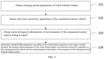
FIG. 2 is a flowchart of an optional self-adaptive adjustment method of flight parameters of an unmanned aerial vehicle for wind turbine inspection according to an embodiment of the disclosure; -
FIG. 3 is a schematic diagram of a self-adaptive adjustment device for flight parameters of an unmanned aerial vehicle for wind turbine inspection according to an embodiment of the disclosure; -
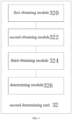
FIG. 4 is a schematic diagram of an optional self-adaptive adjustment device for flight parameters of an unmanned aerial vehicle for wind turbine inspection according to an embodiment of the disclosure; and -
FIG. 5 is a structural block diagram of an electronic apparatus according to the disclosure. - In the following, the disclosure will be described in detail with reference to the attached drawings and embodiments. It should be noted that the embodiments in this disclosure and the features in the embodiments can be combined with each other without conflict.
- The following detailed descriptions are exemplary descriptions and are intended to provide further detailed descriptions of this disclosure. Unless otherwise specified, all technical terms used in this disclosure have the same meaning as commonly understood by ordinary skilled in the field to which this disclosure belongs. The terminology used in this disclosure is only for describing specific embodiments, and is not intended to limit exemplary implementations according to this disclosure.
- As shown in
FIG. 1 ,Embodiment 1 of the disclosure provides a self-adaptive adjustment method of flight parameters of an unmanned aerial vehicle for wind turbine inspection, which includes the following steps. - Step S1, a wind turbine inspection route stage of the unmanned aerial vehicle being currently located is determined during flight of the unmanned aerial vehicle, according to a real-time position of the unmanned aerial vehicle and a relative position relationship between the unmanned aerial vehicle and a wind turbine.
- In this step S1, the controller of the UAV or other hardware equipment with data processing function can be used as the executive body of the method in this scheme, and the whole process of the wind turbine inspection can be carried out in the UAV, this scheme can first determine the real-time position of the UAV and the relative position relationship between the UAV and the wind turbine, such as the UAV is on the front or back of the wind turbine hub or directly above the aircraft cabin, and then based on the real-time position of the UAV and the relative position relationship between the UAV and the wind turbine, which route stage the UAV is in the wind turbine inspection is determined.
- What needs to be explained here is that the route stage of the wind turbine inspection can include any stage of the whole process of taking off, inspection and returning from the UAV.
- As a specific example of the above steps, the route stage includes one or more: take-off stage, wind turbine measurement stage, inspection stage and return stage. This scheme can dynamically and self-adaptively adjust the flight parameters of the UAV after identifying which route stage the UAV is in the wind turbine inspection. In a more specific example, in the take-off stage, the UAV only needs to fly from the take-off position to the target position, and the flight speed can be 8m/s. In the wind turbine measurement stage and inspection stage, the wind turbine needs to open the image acquisition module on the one hand, and on the other hand, it needs to fly slowly, with the flight speed of 1m/s because it is close to the wind turbine and needs to avoid an accident caused by sudden change in the wind turbine yaw angle. In the return stage, the flight speed of the unmanned aerial vehicle can be 8 m/s. In this way, the UAV can be safely and quickly completed in the whole process of wind turbine inspection.
- Step S2, standard flight parameters are determined according to the wind turbine inspection route stage of the unmanned aerial vehicle being currently located.
- In this step S2, the above standard flight parameters can be standard flight speeds, that is, there is a standard flight speed corresponding to each different wind turbine inspection route stage. This scheme can determine which wind turbine inspection route stage the UAV is in and then match it to obtain the corresponding standard flight speed.
- It should be noted here that the standard flight parameters can be standard flight speed or other flight parameters such as flight attitude.
- As shown in
FIG. 2 , this step S2 of determining standard flight parameters according to the wind turbine inspection route stage of the unmanned aerial vehicle being currently located specifically includes the following steps: - step S21: running speed parameters of wind turbine blades are obtained;
- step S22: real-time electricity quantities of the unmanned aerial vehicle are obtained;
- step S23: meteorological information of environment of the unmanned aerial vehicle being located is obtained;
- step S24: standard flight parameters are determined according to the wind turbine inspection route stage currently located, the running speed parameters of the wind turbine blades, the real-time electricity quantities of the unmanned aerial vehicle and the meteorological information of environment of the unmanned aerial vehicle being located.
- As a specific example of the above steps, in this scheme, the standard flight parameters can be determined by integrating the running speed parameters of the wind turbine blades, the real-time electricity quantities of the UAV, the meteorological information of the environment where the UAV is located and the wind turbine inspection route stage currently located, so that the corrected flight parameters of the UAV are more in line with the scene where the UAV is located. In a more specific example, if the wind turbine blades are running at a faster speed at this time, the speed of the UAV can be lowered to ensure the safety of the UAV in the inspection stage. Or in the return stage of the UAV, if the electricity quantity threshold of the UAV is low at this time, this scheme will speed up the flight speed of the UAV, or in the sudden change of weather, such as foggy weather, this scheme will reduce the flight speed of the UAV to avoid safety accidents.
- Step S3, real-time flight parameters of the unmanned aerial vehicle are corrected based on the standard flight parameters to obtain final flight parameters for controlling flight of the unmanned aerial vehicle.
- As an exemplary explanation, after the standard flight speed is obtained, the real-time flight parameters of the UAV can be corrected according to the standard flight parameters according to the preset correction method.
- Optionally, in step S3 of correcting real-time flight parameters of the unmanned aerial vehicle based on the standard flight parameters includes:
step S31, the real-time flight parameters are adjusted into the standard flight parameters according to a preset speed change. - As a specific example of the above steps, in this scheme, after determining the standard flight parameters, the UAV is not directly controlled to fly according to the standard flight parameters, but the real-time flight parameters are adjusted to the standard flight parameters slowly and regularly according to the preset speed change. In this way, it is possible to prevent the sudden increase or decrease of speed from easily causing safety accidents when the standard flight parameters are too different from the real-time flight parameters.
- Step S4, the unmanned aerial vehicle is controlled to fly according to the corrected flight parameters in the wind turbine inspection route stage of currently located.
- What needs to be explained here is that through the above steps, this scheme determines the route stage where the UAV is located according to the real-time position of the UAV, and self-adaptively adjusts the flight parameters of the UAV according to the route stage where the UAV is located. Because the UAV does not need to fly slowly in some route stages, the flight speed in the route stage that does not need to fly slowly can be increased, and the flight speed in the route stage that needs to fly slowly can be reduced. Therefore, this scheme solves the technical problem that the control mode of the unmanned aerial vehicle in the prior art is not flexible enough, and the inspection can only be carried out according to the preset flight speed, and considering the inspection efficiency, the worker often can only set the flight speed according to the lower limit meeting the standard, which leads to the low inspection efficiency of the unmanned aerial vehicle.
- As shown in
FIG. 3 ,Embodiment 2 of the disclosure further provides a self-adaptive adjustment device for flight parameters of an unmanned aerial vehicle for wind turbine inspection, which includes: - a first determining
unit 30, configured to determine a wind turbine inspection route stage of the unmanned aerial vehicle being currently located according to a real-time position of the unmanned aerial vehicle and a relative position relationship between the unmanned aerial vehicle and a wind turbine during flight of the unmanned aerial vehicle; - a second determining
unit 32, configured to determine standard flight parameters according to the wind turbine inspection route stage of the unmanned aerial vehicle being currently located; - a
correction unit 34, configured to correct the real-time flight parameters of the unmanned aerial vehicle based on the standard flight parameters to obtain final flight parameters for controlling flight of the unmanned aerial vehicle. - a
control unit 36, configured to control the unmanned aerial vehicle to fly according to the corrected flight parameters in the wind turbine inspection route stage currently located. - When applied to the embodiment of the disclosure, in the whole process that the UAV performs the wind turbine inspection, the scheme can first determine the real-time position of the UAV and the relative position relationship between the UAV and the wind turbine, such as the drone is located on the front and back of the wind turbine hub or directly above the aircraft cabin, and then determine which route stage the drone is in the wind turbine inspection based on the real-time position of the UAV and the relative position relationship between the UAV and the wind turbine. What needs to be explained here is that the wind turbine inspection route stage can include any stage of the whole process of taking off, inspection and returning from the drone. The above standard flight parameters can be standard flight speeds, that is, there is a standard flight speed corresponding to each different wind turbine inspection route stage. This scheme can determine which wind turbine inspection route stage the UAV is in and then match it to obtain the corresponding standard flight speed. It should be noted here that the standard flight parameters can be standard flight speed or other flight parameters such as flight attitude. After the standard flight speed is obtained, the real-time flight parameters of the UAV can be corrected according to the standard flight parameters according to the preset correction method.
- Through the above aspects, this scheme determines the route stage where the UAV is located according to the real-time position of the UAV, and self-adaptively adjusts the flight parameters of the UAV according to the route stage where the UAV is located. Because the UAV does not need to fly slowly in some route stages, the flight speed in the route stage that does not need to fly slowly can be increased, and the flight speed in the route stage that needs to fly slowly can be reduced. Therefore, this scheme solves the technical problem that in the prior art, the control mode of the unmanned aerial vehicle is not flexible enough, and the inspection can only be carried out according to the preset flight speed, and considering the inspection efficiency, the worker often can only set the flight speed according to the lower limit meeting the standard, which leads to the low inspection efficiency of the unmanned aerial vehicle.
- Optionally, the route stage may include a takeoff stage, a wind turbine measurement stage, an inspection stage, and a return stage.
- As shown in
FIG. 4 , the second determiningunit 32 may include the following: - a first obtaining
module 320, configured to obtain running speed parameters of wind turbine blades; - a second obtaining module 322, configured to obtain real-time electricity quantities of the unmanned aerial vehicle;
- a third obtaining
module 324, configured to obtain meteorological information of environment of the unmanned aerial vehicle being located; - a determining
module 326, configured to determine standard flight parameters according to the wind turbine inspection route stage currently located, the running speed parameters of the wind turbine blades, the real-time electricity quantities of the unmanned aerial vehicle and the meteorological information of environment of the unmanned aerial vehicle being located. - Optionally, the correction unit includes: an adjusting module, configured to adjust the real-time flight parameters into the standard flight parameters according to a preset speed change.
- The disclosure also provides an
electronic apparatus 100 for realizing the the self-adaptive adjustment method of flight parameters of an unmanned aerial vehicle for wind turbine inspection in the above embodiment. Theelectronic apparatus 100 includes amemory 101, at least oneprocessor 102, acomputer program 103 stored in thememory 101 and executable on the at least oneprocessor 102, and at least onecommunication bus 104. Thememory 101 can be used to store acomputer program 103, and theprocessor 102 runs or executes the computer program stored in thememory 101, and calls the data stored in thememory 101 to realize the steps of the self-adaptive adjustment method of flight parameters of an unmanned aerial vehicle for wind turbine inspection in thefirst Embodiment 1. Thememory 101 may mainly include a storage program area and a storage data area, where the storage program area may store an operating system, application programs required by at least one function (such as sound playing function, image playing function, etc.); the storage data area may store data (such as audio data) created according to the use of theelectronic apparatus 100 and the like. In addition, thememory 101 may include a nonvolatile memory, such as a hard disk, a memory, a plug-in hard disk, a smart media card (SMC), a secure digital (SD) card, a flash card, at least one disk memory part, a flash memory part, or other nonvolatile solid-state memory part. - At least one
processor 102 may be a central processing unit (CPU), may also be other general processors, digital signal processor (DSP), application specific integrated circuits (ASIC), field-programmable gate array (FPGA) or other programmable logic part, discrete gate or transistor logic devices, discrete hardware components, etc. Theprocessor 102 can be a microprocessor, or theprocessor 102 can also be any conventional processor, etc. Theprocessor 102 is the control center of theelectronic apparatus 100, and connects various parts of theelectronic apparatus 100 with various interfaces and lines. - The
memory 101 in theelectronic apparatus 100 stores a plurality of instructions to realize the self-adaptive adjustment method of flight parameters of an unmanned aerial vehicle for wind turbine inspection, and theprocessor 102 can execute the plurality of instructions to realize the following: - a wind turbine inspection route stage of the unmanned aerial vehicle being currently located is determined during flight of the unmanned aerial vehicle, according to a real-time position of the unmanned aerial vehicle and a relative position relationship between the unmanned aerial vehicle and a wind turbine;
- standard flight parameters are determined according to the wind turbine inspection route stage of the unmanned aerial vehicle being currently located;
- real-time flight parameters of the unmanned aerial vehicle are corrected based on the standard flight parameters;
- the unmanned aerial vehicle is controlled to fly according to the corrected flight parameters in the wind turbine inspection route stage currently located.
- The integrated modules/units of the
electronic apparatus 100 can be stored in a computer-readable storage medium if they are implemented in the form of software functional units and sold or used as independent products. Based on this understanding, the disclosure can realize all or part of the processes in the methods of the above-mentioned embodiments, and can also instruct related hardware through a computer program, computer program can be stored in a computer-readable storage medium, and when the computer program is executed by a processor, can realize the each step of the above method embodiment. Where, the computer program includes computer program code, which can be in the form of source code, object code, executable file or some intermediate form. Computer-readable media can include any entity or device capable of carrying computer program codes, recording media, U disk, mobile hard disk, magnetic disk, optical disk, computer memory and read-only memory. - It should be understood by those skilled in the art that embodiments of the disclosure can be provided as a method, a system, or a computer program product. Therefore, this disclosure can take the form of an entirely hardware embodiment, an entirely software embodiment, or an embodiment combining software and hardware aspects. Moreover, this disclosure can take the form of a computer program product implemented on one or more computer-usable storage media (including but not limited to disk storage, CD-ROM, optical storage, etc.) containing computer-usable program codes.
- The disclosure is described with reference to flowcharts and/or block diagrams of methods, devices (systems), and computer program products according to embodiments of the disclosure. It should be understood that each flow and/or block in the flowchart and/or block diagram, and combinations of the flow and/or block in the flowchart and/or block diagram can be implemented by computer program instructions. These computer program instructions may be provided to a processor of a general-purpose computer, special-purpose computer, embedded processor or other programmable data processing apparatus to produce a machine, such that the instructions which are executed by the processor of the computer or other programmable data processing apparatus produce means for implementing the functions specified in one or more flows in the flowchart and/or one or more blocks in the block diagram.
- These computer program instructions may also be stored in a computer-readable memory that can direct a computer or other programmable data processing apparatus to work in a particular manner, such that the instructions stored in the computer-readable memory produce an article of manufacture including instruction means. The instruction means implements the functions specified in one or more flows in the flowchart and/or one or more blocks in the block diagram.
- These computer program instructions can also be loaded onto a computer or other programmable data processing device, so that a series of operational steps are performed on the computer or other programmable device to produce computer-implemented processes, so that the instructions executed on the computer or other programmable device provide steps for implementing the functions specified in one or more flows in the flowchart and/or one or more blocks in the block diagrams.
- Finally, it should be explained that the above embodiments are only used to illustrate the technical scheme of this disclosure, but not to limit it. Although this disclosure has been described in detail with reference to the above embodiments, ordinary skilled in the field should understand that the specific embodiments of this disclosure can still be modified or replaced by equivalents, without any modification or equivalent replacement that deviates from the spirit and scope of this disclosure, which should be included in the scope of protection of the claims of this disclosure.
Claims (10)
- A self-adaptive adjustment method of flight parameters of an unmanned aerial vehicle for wind turbine inspection, comprising:determining a wind turbine inspection route stage of the unmanned aerial vehicle being currently located during flight of the unmanned aerial vehicle, according to a real-time position of the unmanned aerial vehicle and a relative position relationship between the unmanned aerial vehicle and a wind turbine;determining standard flight parameters according to the wind turbine inspection route stage of the unmanned aerial vehicle being currently located;correcting real-time flight parameters of the unmanned aerial vehicle based on the standard flight parameters to obtain final flight parameters for controlling flight of the unmanned aerial vehicle.
- The self-adaptive adjustment method of flight parameters of an unmanned aerial vehicle for wind turbine inspection according to claim 1, wherein in step of determining a wind turbine inspection route stage of the unmanned aerial vehicle being currently located during flight of the unmanned aerial vehicle, according to a real-time position of the unmanned aerial vehicle and a relative position relationship between the unmanned aerial vehicle and a wind turbine, the wind turbine inspection route stage comprises one or more of a take-off stage, a wind turbine measurement stage, an inspection stage and a return stage.
- The self-adaptive adjustment method of flight parameters of an unmanned aerial vehicle for wind turbine inspection according to claim 1, wherein in step of determining standard flight parameters according to the wind turbine inspection route stage of the unmanned aerial vehicle being currently located comprises:obtaining running speed parameters of wind turbine blades;obtaining real-time electricity quantities of the unmanned aerial vehicle;obtaining meteorological information of environment of the unmanned aerial vehicle being located;determining standard flight parameters according to the wind turbine inspection route stage currently located, the running speed parameters of the wind turbine blades, the real-time electricity quantities of the unmanned aerial vehicle and the meteorological information of environment of the unmanned aerial vehicle being located.
- The self-adaptive adjustment method of flight parameters of an unmanned aerial vehicle for wind turbine inspection according to claim 1, wherein in step of correcting real-time flight parameters of the unmanned aerial vehicle based on the standard flight parameters comprises:
adjusting the real-time flight parameters into the standard flight parameters according to a preset speed change. - A self-adaptive adjustment device for flight parameters of an unmanned aerial vehicle for wind turbine inspection, comprising:a first determining unit, configured to determine a wind turbine inspection route stage of the unmanned aerial vehicle being currently located according to a real-time position of the unmanned aerial vehicle and a relative position relationship between the unmanned aerial vehicle and a wind turbine during flight of the unmanned aerial vehicle;a second determining unit, configured to determine standard flight parameters according to the wind turbine inspection route stage of the unmanned aerial vehicle being currently located;a correction unit, configured to correct the real-time flight parameters of the unmanned aerial vehicle based on the standard flight parameters to obtain final flight parameters for controlling flight of the unmanned aerial vehicle.
- The self-adaptive adjustment device for flight parameters of an unmanned aerial vehicle for wind turbine inspection according to claim 5, wherein the wind turbine inspection route stage comprises one or more of a takeoff stage, a wind turbine measurement stage, an inspection stage and a return stage.
- The self-adaptive adjustment device for flight parameters of an unmanned aerial vehicle for wind turbine inspection according to claim 5, wherein the second determining unit comprises:a first obtaining module, configured to obtain running speed parameters of wind turbine blades;a second obtaining module, configured to obtain real-time electricity quantities of the unmanned aerial vehicle;a third obtaining module, configured to obtain meteorological information of environment of the unmanned aerial vehicle being located;a determining module, configured to determine standard flight parameters according to the wind turbine inspection route stage currently located, the running speed parameters of the wind turbine blades, the real-time electricity quantities of the unmanned aerial vehicle and the meteorological information of environment of the unmanned aerial vehicle being located, so as to obtain the final flight parameters for controlling flight of the unmanned aerial vehicle.
- The self-adaptive adjustment device for flight parameters of an unmanned aerial vehicle for wind turbine inspection according to claim 5, wherein the correction unit comprises:
an adjusting module, configured to adjust the real-time flight parameters into the standard flight parameters according to a preset speed change. - An electronic apparatus, comprising a processor and a memory, wherein the processor is used for executing a computer program stored in the memory to realize the self-adaptive adjustment method of flight parameters of an unmanned aerial vehicle for wind turbine inspection according to any one of claims 1 to 4.
- A computer-readable storage medium, wherein at least one instruction is stored in the computer-readable storage medium, and when the at least one instruction is executed by a processor, the self-adaptive adjustment method of flight parameters of an unmanned aerial vehicle for wind turbine inspection according to any one of claims 1 to 4 is realized.
Applications Claiming Priority (2)
| Application Number | Priority Date | Filing Date | Title |
|---|---|---|---|
| CN202210843042.6A CN114967726B (en) | 2022-07-18 | 2022-07-18 | Adaptive adjustment method, device and equipment for flight parameters of wind turbine inspection drone |
| PCT/CN2023/079046 WO2024016675A1 (en) | 2022-07-18 | 2023-03-01 | Adaptive adjustment method and apparatus for flight parameters of wind turbine inspection unmanned aerial vehicle, device, and storage medium |
Publications (3)
| Publication Number | Publication Date |
|---|---|
| EP4560424A1 true EP4560424A1 (en) | 2025-05-28 |
| EP4560424A4 EP4560424A4 (en) | 2025-10-29 |
| EP4560424B1 EP4560424B1 (en) | 2026-04-22 |
Family
ID=82969701
Family Applications (1)
| Application Number | Title | Priority Date | Filing Date |
|---|---|---|---|
| EP23841753.9A Active EP4560424B1 (en) | 2022-07-18 | 2023-03-01 | Adaptive adjustment method and apparatus for flight parameters of wind turbine inspection unmanned aerial vehicle, device, and storage medium |
Country Status (3)
| Country | Link |
|---|---|
| EP (1) | EP4560424B1 (en) |
| CN (1) | CN114967726B (en) |
| WO (1) | WO2024016675A1 (en) |
Families Citing this family (8)
| Publication number | Priority date | Publication date | Assignee | Title |
|---|---|---|---|---|
| CN114967726B (en) * | 2022-07-18 | 2025-02-07 | 中国华能集团清洁能源技术研究院有限公司 | Adaptive adjustment method, device and equipment for flight parameters of wind turbine inspection drone |
| CN116591908B (en) * | 2023-04-25 | 2026-04-17 | 星逻人工智能技术(上海)有限公司 | A method for calculating the dynamic safety range of wind turbine inspection without shutting down |
| CN117151311B (en) * | 2023-10-31 | 2024-02-02 | 天津云圣智能科技有限责任公司 | Mapping parameter optimization processing method and device, electronic equipment and storage medium |
| CN118553030A (en) * | 2024-06-27 | 2024-08-27 | 深圳市朗驰欣创科技股份有限公司 | Intelligent inspection method and system for wind power plant based on unmanned aerial vehicle |
| CN118963396B (en) * | 2024-07-29 | 2025-10-24 | 锐川机器人(深圳)有限公司 | Intelligent flight control system and method for vertical take-off unmanned aerial vehicle |
| CN119002516B (en) * | 2024-10-22 | 2024-12-20 | 国网甘肃省电力公司经济技术研究院 | Self-adaptive control method, system, terminal and medium for inspection of cable tunnel unmanned aerial vehicle |
| CN119472738B (en) * | 2025-01-06 | 2025-07-29 | 西安羚控电子科技有限公司 | Unmanned plane jet system cooperation method, unmanned plane jet system cooperation device and storage medium |
| CN119672583B (en) * | 2025-02-19 | 2025-04-22 | 南京启征信息技术有限公司 | Power engineering defect diagnosis method based on AI image recognition and blockchain technology |
Family Cites Families (11)
| Publication number | Priority date | Publication date | Assignee | Title |
|---|---|---|---|---|
| CN101620278A (en) * | 2009-07-02 | 2010-01-06 | 浙江省电力公司 | Method for helicopter power patrol on board system to control image collection |
| CN107340781A (en) * | 2016-09-30 | 2017-11-10 | 广州亿航智能技术有限公司 | UAV flight control method and system |
| PT3454159T (en) * | 2017-09-06 | 2020-03-11 | Alerion Tech S L | AUTONOMOUS NAVIGATION METHOD AND DEVICE |
| FR3080691B1 (en) * | 2018-04-25 | 2020-05-29 | Airbus Operations (S.A.S.) | METHOD AND DEVICE FOR AIDING THE OPERATION OF AN AIRCRAFT TO RESPECT A PASSING TIME CONSTRAINT |
| WO2020154942A1 (en) * | 2019-01-30 | 2020-08-06 | 深圳市大疆创新科技有限公司 | Control method for unmanned aerial vehicle, and unmanned aerial vehicle |
| CN112068539A (en) * | 2019-05-23 | 2020-12-11 | 李峥嵘 | Unmanned aerial vehicle automatic driving inspection method for blades of wind turbine generator |
| CN112925335B (en) * | 2019-12-06 | 2024-10-01 | 丰翼科技(深圳)有限公司 | Unmanned aerial vehicle communication method, unmanned aerial vehicle communication device, computer readable storage medium and computer readable storage device |
| CN113939452B (en) * | 2020-05-22 | 2024-05-17 | 深圳市大疆创新科技有限公司 | Spraying control method and device |
| CN112947511A (en) * | 2021-01-25 | 2021-06-11 | 北京京能能源技术研究有限责任公司 | Method for inspecting fan blade by unmanned aerial vehicle |
| CN113485453B (en) * | 2021-08-20 | 2024-05-10 | 中国华能集团清洁能源技术研究院有限公司 | Method and device for generating inspection flight path of marine unmanned aerial vehicle and unmanned aerial vehicle |
| CN114967726B (en) * | 2022-07-18 | 2025-02-07 | 中国华能集团清洁能源技术研究院有限公司 | Adaptive adjustment method, device and equipment for flight parameters of wind turbine inspection drone |
-
2022
- 2022-07-18 CN CN202210843042.6A patent/CN114967726B/en active Active
-
2023
- 2023-03-01 WO PCT/CN2023/079046 patent/WO2024016675A1/en not_active Ceased
- 2023-03-01 EP EP23841753.9A patent/EP4560424B1/en active Active
Also Published As
| Publication number | Publication date |
|---|---|
| CN114967726B (en) | 2025-02-07 |
| WO2024016675A1 (en) | 2024-01-25 |
| EP4560424A4 (en) | 2025-10-29 |
| CN114967726A (en) | 2022-08-30 |
| EP4560424B1 (en) | 2026-04-22 |
Similar Documents
| Publication | Publication Date | Title |
|---|---|---|
| EP4560424B1 (en) | Adaptive adjustment method and apparatus for flight parameters of wind turbine inspection unmanned aerial vehicle, device, and storage medium | |
| CN105739512B (en) | Unmanned plane automatic tour inspection system and method | |
| CN109792951B (en) | Unmanned aerial vehicle air route correction system for pollination of hybrid rice and correction method thereof | |
| US9889870B2 (en) | Driving curve creation device, driving assistance device, driving control device, and driving curve creation method | |
| CN107830864A (en) | A kind of aircarrier aircraft bad weather is diversion route planning system and method | |
| RU2011119087A (en) | METHOD AND SYSTEM OF CONTROL OF AUTOMATIC LANDING / Take-off of an unmanned aerial vehicle on a round landing grid of the platform, in particular the marine platform | |
| CN110531780A (en) | Unmanned plane full-automation cruising inspection system and method based on automatic airport | |
| CN114757454B (en) | Unmanned aerial vehicle inspection route generation method, device and equipment of wind driven generator | |
| CN112947511A (en) | Method for inspecting fan blade by unmanned aerial vehicle | |
| CN102566580A (en) | Unmanned helicopter flight track planning method | |
| CN114020007B (en) | Unmanned aerial vehicle and unmanned aerial vehicle train team patrol method, system, device and storage medium | |
| US11854411B2 (en) | Coordinating drone flights in an operating wind farm | |
| CN112068539A (en) | Unmanned aerial vehicle automatic driving inspection method for blades of wind turbine generator | |
| CN105109480A (en) | Intelligent u-turn method and device | |
| CN115076049A (en) | Method and device for determining yaw angle of fan, storage medium and electronic equipment | |
| CN112666995A (en) | Unmanned aerial vehicle speed planning method, device, equipment and storage medium | |
| CN118605567A (en) | A method for correcting the trajectory of autonomous inspection by unmanned aerial vehicles | |
| CN106970632B (en) | A Precise Operation Method of Rotor UAV Based on Steady-State Motion of Canopy Vortex | |
| CN105700554A (en) | Fixed-wing unmanned aerial vehicle landing method and fixed-wing unmanned aerial vehicle landing system | |
| CN112154395B (en) | Flight control method, system, unmanned aerial vehicle and storage medium | |
| CN114966740B (en) | Vehicle laser radar control system and control method | |
| CN119200647A (en) | A UAV follow-up landing method and system based on active airport compensation | |
| CN116374165A (en) | Aircraft brake control method and system | |
| CN117930881A (en) | A UAV control method and system based on deep learning | |
| CN112306080A (en) | Unmanned aerial vehicle formation flying method and system |
Legal Events
| Date | Code | Title | Description |
|---|---|---|---|
| STAA | Information on the status of an ep patent application or granted ep patent |
Free format text: STATUS: THE INTERNATIONAL PUBLICATION HAS BEEN MADE |
|
| PUAI | Public reference made under article 153(3) epc to a published international application that has entered the european phase |
Free format text: ORIGINAL CODE: 0009012 |
|
| STAA | Information on the status of an ep patent application or granted ep patent |
Free format text: STATUS: REQUEST FOR EXAMINATION WAS MADE |
|
| 17P | Request for examination filed |
Effective date: 20250314 |
|
| AK | Designated contracting states |
Kind code of ref document: A1 Designated state(s): AL AT BE BG CH CY CZ DE DK EE ES FI FR GB GR HR HU IE IS IT LI LT LU LV MC ME MK MT NL NO PL PT RO RS SE SI SK SM TR |
|
| REG | Reference to a national code |
Ref country code: DE Ref legal event code: R079 Free format text: PREVIOUS MAIN CLASS: G05D0001225000 Ipc: G05D0001689000 Ref country code: DE Ref legal event code: R079 Ref document number: 602023015875 Country of ref document: DE Free format text: PREVIOUS MAIN CLASS: G05D0001225000 Ipc: G05D0001689000 |
|
| STAA | Information on the status of an ep patent application or granted ep patent |
Free format text: STATUS: EXAMINATION IS IN PROGRESS |
|
| DAV | Request for validation of the european patent (deleted) | ||
| DAX | Request for extension of the european patent (deleted) | ||
| A4 | Supplementary search report drawn up and despatched |
Effective date: 20250929 |
|
| RIC1 | Information provided on ipc code assigned before grant |
Ipc: G05D 1/689 20240101AFI20250923BHEP Ipc: G05D 1/225 20240101ALI20250923BHEP Ipc: G05D 1/606 20240101ALI20250923BHEP Ipc: G05D 105/80 20240101ALI20250923BHEP Ipc: G05D 107/70 20240101ALI20250923BHEP Ipc: G05D 109/25 20240101ALI20250923BHEP Ipc: G05D 1/65 20240101ALI20250923BHEP Ipc: B64U 101/26 20230101ALI20250923BHEP |
|
| 17Q | First examination report despatched |
Effective date: 20251010 |
|
| GRAP | Despatch of communication of intention to grant a patent |
Free format text: ORIGINAL CODE: EPIDOSNIGR1 |
|
| STAA | Information on the status of an ep patent application or granted ep patent |
Free format text: STATUS: GRANT OF PATENT IS INTENDED |
|
| GRAS | Grant fee paid |
Free format text: ORIGINAL CODE: EPIDOSNIGR3 |
|
| INTG | Intention to grant announced |
Effective date: 20260209 |
|
| GRAA | (expected) grant |
Free format text: ORIGINAL CODE: 0009210 |
|
| STAA | Information on the status of an ep patent application or granted ep patent |
Free format text: STATUS: THE PATENT HAS BEEN GRANTED |
|
| AK | Designated contracting states |
Kind code of ref document: B1 Designated state(s): AL AT BE BG CH CY CZ DE DK EE ES FI FR GB GR HR HU IE IS IT LI LT LU LV MC ME MK MT NL NO PL PT RO RS SE SI SK SM TR |
|
| REG | Reference to a national code |
Ref country code: CH Ref legal event code: F10 Free format text: ST27 STATUS EVENT CODE: U-0-0-F10-F00 (AS PROVIDED BY THE NATIONAL OFFICE) Effective date: 20260422 Ref country code: GB Ref legal event code: FG4D |
|
| REG | Reference to a national code |
Ref country code: DE Ref legal event code: R096 Ref document number: 602023015875 Country of ref document: DE |