EP4560418A1 - System and method for machining a workpiece installed on a rotary table - Google Patents
System and method for machining a workpiece installed on a rotary table Download PDFInfo
- Publication number
- EP4560418A1 EP4560418A1 EP24214938.3A EP24214938A EP4560418A1 EP 4560418 A1 EP4560418 A1 EP 4560418A1 EP 24214938 A EP24214938 A EP 24214938A EP 4560418 A1 EP4560418 A1 EP 4560418A1
- Authority
- EP
- European Patent Office
- Prior art keywords
- workpiece
- rotation
- machining
- vector
- orientation
- Prior art date
- Legal status (The legal status is an assumption and is not a legal conclusion. Google has not performed a legal analysis and makes no representation as to the accuracy of the status listed.)
- Pending
Links
Images




Classifications
-
- B—PERFORMING OPERATIONS; TRANSPORTING
- B23—MACHINE TOOLS; METAL-WORKING NOT OTHERWISE PROVIDED FOR
- B23P—METAL-WORKING NOT OTHERWISE PROVIDED FOR; COMBINED OPERATIONS; UNIVERSAL MACHINE TOOLS
- B23P15/00—Making specific metal objects by operations not covered by a single other subclass or a group in this subclass
- B23P15/02—Making specific metal objects by operations not covered by a single other subclass or a group in this subclass turbine or like blades from one piece
-
- F—MECHANICAL ENGINEERING; LIGHTING; HEATING; WEAPONS; BLASTING
- F01—MACHINES OR ENGINES IN GENERAL; ENGINE PLANTS IN GENERAL; STEAM ENGINES
- F01D—NON-POSITIVE DISPLACEMENT MACHINES OR ENGINES, e.g. STEAM TURBINES
- F01D5/00—Blades; Blade-carrying members; Heating, heat-insulating, cooling or antivibration means on the blades or the members
- F01D5/12—Blades
-
- G—PHYSICS
- G05—CONTROLLING; REGULATING
- G05B—CONTROL OR REGULATING SYSTEMS IN GENERAL; FUNCTIONAL ELEMENTS OF SUCH SYSTEMS; MONITORING OR TESTING ARRANGEMENTS FOR SUCH SYSTEMS OR ELEMENTS
- G05B19/00—Program-control systems
- G05B19/02—Program-control systems electric
- G05B19/18—Numerical control [NC], i.e. automatically operating machines, in particular machine tools, e.g. in a manufacturing environment, so as to execute positioning, movement or co-ordinated operations by means of program data in numerical form
- G05B19/401—Numerical control [NC], i.e. automatically operating machines, in particular machine tools, e.g. in a manufacturing environment, so as to execute positioning, movement or co-ordinated operations by means of program data in numerical form characterised by control arrangements for measuring, e.g. calibration and initialisation, measuring workpiece for machining purposes
-
- G—PHYSICS
- G05—CONTROLLING; REGULATING
- G05B—CONTROL OR REGULATING SYSTEMS IN GENERAL; FUNCTIONAL ELEMENTS OF SUCH SYSTEMS; MONITORING OR TESTING ARRANGEMENTS FOR SUCH SYSTEMS OR ELEMENTS
- G05B19/00—Program-control systems
- G05B19/02—Program-control systems electric
- G05B19/18—Numerical control [NC], i.e. automatically operating machines, in particular machine tools, e.g. in a manufacturing environment, so as to execute positioning, movement or co-ordinated operations by means of program data in numerical form
- G05B19/402—Numerical control [NC], i.e. automatically operating machines, in particular machine tools, e.g. in a manufacturing environment, so as to execute positioning, movement or co-ordinated operations by means of program data in numerical form characterised by control arrangements for positioning, e.g. centring a tool relative to a hole in the workpiece, additional detection means to correct position
-
- G—PHYSICS
- G05—CONTROLLING; REGULATING
- G05B—CONTROL OR REGULATING SYSTEMS IN GENERAL; FUNCTIONAL ELEMENTS OF SUCH SYSTEMS; MONITORING OR TESTING ARRANGEMENTS FOR SUCH SYSTEMS OR ELEMENTS
- G05B19/00—Program-control systems
- G05B19/02—Program-control systems electric
- G05B19/18—Numerical control [NC], i.e. automatically operating machines, in particular machine tools, e.g. in a manufacturing environment, so as to execute positioning, movement or co-ordinated operations by means of program data in numerical form
- G05B19/404—Numerical control [NC], i.e. automatically operating machines, in particular machine tools, e.g. in a manufacturing environment, so as to execute positioning, movement or co-ordinated operations by means of program data in numerical form characterised by control arrangements for compensation, e.g. for backlash, overshoot, tool offset, tool wear, temperature, machine construction errors, load, inertia
-
- F—MECHANICAL ENGINEERING; LIGHTING; HEATING; WEAPONS; BLASTING
- F05—INDEXING SCHEMES RELATING TO ENGINES OR PUMPS IN VARIOUS SUBCLASSES OF CLASSES F01-F04
- F05D—INDEXING SCHEME FOR ASPECTS RELATING TO NON-POSITIVE-DISPLACEMENT MACHINES OR ENGINES, GAS-TURBINES OR JET-PROPULSION PLANTS
- F05D2220/00—Application
- F05D2220/30—Application in turbines
- F05D2220/32—Application in turbines in gas turbines
- F05D2220/323—Application in turbines in gas turbines for aircraft propulsion, e.g. jet engines
-
- F—MECHANICAL ENGINEERING; LIGHTING; HEATING; WEAPONS; BLASTING
- F05—INDEXING SCHEMES RELATING TO ENGINES OR PUMPS IN VARIOUS SUBCLASSES OF CLASSES F01-F04
- F05D—INDEXING SCHEME FOR ASPECTS RELATING TO NON-POSITIVE-DISPLACEMENT MACHINES OR ENGINES, GAS-TURBINES OR JET-PROPULSION PLANTS
- F05D2230/00—Manufacture
- F05D2230/10—Manufacture by removing material
-
- F—MECHANICAL ENGINEERING; LIGHTING; HEATING; WEAPONS; BLASTING
- F05—INDEXING SCHEMES RELATING TO ENGINES OR PUMPS IN VARIOUS SUBCLASSES OF CLASSES F01-F04
- F05D—INDEXING SCHEME FOR ASPECTS RELATING TO NON-POSITIVE-DISPLACEMENT MACHINES OR ENGINES, GAS-TURBINES OR JET-PROPULSION PLANTS
- F05D2240/00—Components
- F05D2240/20—Rotors
- F05D2240/30—Characteristics of rotor blades, i.e. of any element transforming dynamic fluid energy to or from rotational energy and being attached to a rotor
-
- G—PHYSICS
- G05—CONTROLLING; REGULATING
- G05B—CONTROL OR REGULATING SYSTEMS IN GENERAL; FUNCTIONAL ELEMENTS OF SUCH SYSTEMS; MONITORING OR TESTING ARRANGEMENTS FOR SUCH SYSTEMS OR ELEMENTS
- G05B2219/00—Program-control systems
- G05B2219/30—Nc systems
- G05B2219/37—Measurements
- G05B2219/37339—Eccentricity, cylindricity, circularity
-
- G—PHYSICS
- G05—CONTROLLING; REGULATING
- G05B—CONTROL OR REGULATING SYSTEMS IN GENERAL; FUNCTIONAL ELEMENTS OF SUCH SYSTEMS; MONITORING OR TESTING ARRANGEMENTS FOR SUCH SYSTEMS OR ELEMENTS
- G05B2219/00—Program-control systems
- G05B2219/30—Nc systems
- G05B2219/40—Robotics, robotics mapping to robotics vision
- G05B2219/40555—Orientation and distance
-
- G—PHYSICS
- G05—CONTROLLING; REGULATING
- G05B—CONTROL OR REGULATING SYSTEMS IN GENERAL; FUNCTIONAL ELEMENTS OF SUCH SYSTEMS; MONITORING OR TESTING ARRANGEMENTS FOR SUCH SYSTEMS OR ELEMENTS
- G05B2219/00—Program-control systems
- G05B2219/30—Nc systems
- G05B2219/45—Nc applications
- G05B2219/45043—EDM machine, wire cutting
-
- G—PHYSICS
- G05—CONTROLLING; REGULATING
- G05B—CONTROL OR REGULATING SYSTEMS IN GENERAL; FUNCTIONAL ELEMENTS OF SUCH SYSTEMS; MONITORING OR TESTING ARRANGEMENTS FOR SUCH SYSTEMS OR ELEMENTS
- G05B2219/00—Program-control systems
- G05B2219/30—Nc systems
- G05B2219/45—Nc applications
- G05B2219/45221—Edm, electrical discharge machining, electroerosion, ecm, chemical
-
- G—PHYSICS
- G05—CONTROLLING; REGULATING
- G05B—CONTROL OR REGULATING SYSTEMS IN GENERAL; FUNCTIONAL ELEMENTS OF SUCH SYSTEMS; MONITORING OR TESTING ARRANGEMENTS FOR SUCH SYSTEMS OR ELEMENTS
- G05B2219/00—Program-control systems
- G05B2219/30—Nc systems
- G05B2219/49—Nc machine tool, till multiple
- G05B2219/49313—Machining about eccentric center different from rotational center of workpiece
Definitions
- Machining systems may be used to accomplish one or more workpiece machining (e.g., drilling, grinding, milling, polishing, three-dimensional (3D) printing, etc.) operations for component manufacture.
- workpiece machining e.g., drilling, grinding, milling, polishing, three-dimensional (3D) printing, etc.
- 3D three-dimensional
- a machining system for machining a workpiece to form an aircraft engine component includes a machining assembly, a rotary table, a dimensional measurement assembly, and a controller.
- the machining assembly is configured for machining the workpiece.
- the rotary table is configured to rotate the workpiece about a rotational axis.
- the dimensional measurement assembly includes at least one dimensional measurement sensor.
- the controller includes a processor in communication with a non-transitory memory storing instructions, which instructions when executed by the processor, cause the processor to control the dimensional measurement assembly to identify a first position and a first orientation for a point on a surface of the workpiece with the at least one dimensional measurement sensor, determine a first machine-workpiece vector and a first rotation-workpiece vector for the point, control the rotary table to rotate the workpiece about the rotational axis by a rotation angle, calculate a second position and a second orientation for the point subsequent to rotating the workpiece by rotating the first orientation about the rotational axis by the rotation angle to calculate the second orientation, rotating the first rotation-workpiece vector about the rotational axis by the rotation angle to calculate a second rotation-workpiece vector, and determining a second machine-workpiece vector using the second rotation-workpiece vector to calculate the second position, update a workpiece position and a workpiece orientation in a coordinate system for the workpiece using the second position and the second orientation for the point, and control the machining assembly to machine
- the first machine-workpiece vector may extend between and to a machine origin at the machining assembly and the first position and the second machine-workpiece vector may extend between and to the machine origin and the second position.
- the first rotation-workpiece vector may extend between and to a rotation origin at the rotational axis and the first position and the second rotation-workpiece vector may extend between and to the rotation origin and the second position.
- determining the first rotation-workpiece vector may include determining the first rotation-workpiece vector using the first machine-workpiece vector and a machine-rotation vector.
- the machine-rotation vector may extend between and to a machine origin at the machining assembly and a rotation origin at the rotational axis.
- the machining assembly may include a wire electric discharge machining (WEDM) system.
- WEDM wire electric discharge machining
- the at least one dimensional measurement sensor may include a touch probe.
- the instructions when executed by the processor, may further cause the processor to control the rotary table to hold the workpiece stationary while calculating the second position and the second orientation for each point of the at least one point, updating the workpiece position and the workpiece orientation in the PCS, and controlling the machining assembly to machine the workpiece using the updated workpiece position and updated workpiece orientation.
- a method for machining a workpiece installed on a rotary table to form an aircraft engine component includes positioning the workpiece on the rotary table, identifying a first position and a first orientation for at least one point on one or more surfaces of the workpiece using at least one dimensional measurement sensor, determining a first machine-workpiece vector and a first rotation-workpiece vector for the at least one point, and machining the workpiece at a plurality of circumferential positions by, for each circumferential position of the plurality of circumferential positions, sequentially: rotating the workpiece with the rotary table about a rotational axis by a rotation angle to one circumferential position of the plurality of circumferential positions, calculating a second position and a second orientation for the at least one point by rotating the first orientation about the rotational axis by the rotation angle to calculate the second orientation, rotating the first rotation-workpiece vector about the rotational axis by the rotation angle to calculate a second rotation-workpiece vector, and determining a second machine-
- positioning the workpiece on the rotary table may include positioning the workpiece with a centerline axis of the workpiece offset from the rotational axis.
- the first machine-workpiece vector may extend between and to a machine origin at the machining assembly and the first position and the second machine-workpiece vector may extend between and to the machine origin and the second position.
- the first rotation-workpiece vector may extend between and to a rotation origin at the rotational axis and the first position and the second rotation-workpiece vector may extend between and to the rotation origin and the second position.
- determining the first rotation-workpiece vector may include determining the first rotation-workpiece vector using the first machine-workpiece vector and a machine-rotation vector.
- the machine-rotation vector may extend between and to a machine origin at the machining assembly and a rotation origin at the rotational axis.
- the method may further include positioning the rotary table in a predetermined rotational position prior to identifying the first position and the first orientation.
- machining the workpiece at the one circumferential position may include forming a slot in the workpiece at the one circumferential position with the machining assembly.
- a machining system for machining a workpiece to form an aircraft engine component includes a machining assembly, a rotary table, the workpiece, a dimensional measurement assembly, and a controller.
- the rotary table includes a rotatable platform configured for rotation about a rotational axis.
- the workpiece is positioned on the rotatable platform.
- the workpiece has a centerline axis.
- the workpiece is positioned on the rotary table with the centerline axis offset from the rotational axis.
- the dimensional measurement assembly includes a touch probe.
- the controller includes a processor in communication with a non-transitory memory storing instructions including computer numerical control (CNC) instructions, which instructions when executed by the processor, cause the processor to control the dimensional measurement assembly to identify a first position and a first orientation for at least one point on one or more surfaces of the workpiece with the touch probe, determine a first machine-workpiece vector and a first rotation-workpiece vector for the at least one point, and machine the workpiece at a plurality of circumferential positions by, for each circumferential position of the plurality of circumferential positions, sequentially controlling the rotary table to rotate the workpiece about the rotational axis by a rotation angle to one circumferential position of the plurality of circumferential positions, determining a second position and a second orientation for each point of the at least one point with the workpiece in the one circumferential position, updating a workpiece position and a workpiece orientation in a coordinate system for the workpiece using the second position and the second orientation, and controlling the machining assembly to machine the workpiece using the updated workpiece
- the centerline axis may be skewed relative to the rotational axis.
- controlling the machining assembly to machine the workpiece may include controlling the machining assembly to machine the workpiece at the one circumferential position by forming a slot in the workpiece at the one circumferential position with the machining assembly.
- determining the second position and the second orientation for each point of the at least one point may include determining the second position and the second orientation for the at least one point without identifying the second position and the second orientation using the touch probe.
- the machining assembly may include a wire electric discharge machining (WEDM) system.
- WEDM wire electric discharge machining
- the WEDM system may include an upper feed member and a lower feed member configured for translation and rotation relative to the workpiece.
- the upper feed member and the lower feed member may be configured to machine the workpiece using a wire fed between the upper feed member and the lower feed member.
- the first position may be different than the second position and the first orientation may be different than the second orientation for each point of the at least one point.
- FIG. 1 diagrammatically illustrates a machining system 10.
- the machining system 10 of FIG. 1 is a computer numeric control (CNC) machining system configured for automated control of one or more machining tools for use in the machining of a workpiece 1000 to form a machined component.
- the workpiece 1000 of FIG. 1 may be machined to form a disk which may form a portion of a bladed rotor (e.g., a bladed turbine rotor, a bladed fan rotor, etc.) of a gas turbine engine for an aircraft propulsion system.
- the present disclosure is not limited to any particular workpiece 1000 or machined component type, configuration, or material.
- the machining system 10 of FIG. 1 includes a machining assembly 12, a rotary table 14, a dimensional measurement assembly 16, and a controller 18.
- FIG. 2 diagrammatically illustrates a partial cutaway view of the machining assembly 12 and the rotary table 14 relative to the workpiece 1000.
- the machining assembly 12 of FIG. 2 includes a wire electric discharge machining (WEDM) system 20.
- the WEDM system 20 of FIG. 2 includes an upper feed member 22 and a lower feed member 24 configured, for example, to continuously feed a wire 26 from the upper feed member 22 to the lower feed member 24 during a machining operation for the workpiece 1000.
- the WEDM system 20 (e.g., the upper feed member 22 and the lower feed member 24) may be configured to translate along and/or rotate about one or more of an x-axis, a y-axis, and a z-axis.
- the present disclosure machining assembly 12, however, is not limited to WEDM systems and may alternatively include other configurations of machining (e.g., milling, drilling, grinding, turning, cutting, boring, etc.) systems and tools.
- the rotary table 14 includes a rotatable platform 28.
- the rotatable platform 28 is rotatable about a rotational axis 30 of the rotary table 14.
- the rotational axis 30 of FIG. 2 may be understood to be oriented along the Z-axis, however, the present disclosure is not limited to this particular orientation of the rotational axis 30.
- the rotatable platform 28 is configured to securely retain the workpiece 1000 and to rotate the workpiece 1000 about the rotational axis 30 to position the workpiece 1000 relative to the machining assembly 12.
- the rotatable platform 28 may include fasteners (e.g., mechanical fasteners) and/or other mounting hardware for securely mounting or otherwise retaining the workpiece 1000 on the rotatable platform 28.
- FIG. 3 diagrammatically illustrates a side view of the dimensional measurement assembly 16 and the rotary table 14 relative to the workpiece 1000.
- the dimensional measurement assembly 16 includes one or more dimensional measurement sensors 32.
- the dimensional measurement sensor 32 of FIG. 3 is configured as a touch probe 34.
- the touch probe 34 of FIG. 3 is configured to identify positions of the workpiece 1000 (e.g., workpiece surface positions) relative to a three-dimensional coordinate space based on physical contact between the touch probe 34 and the workpiece 1000.
- the touch probe 34 may be used to measure the shape, size, curvature, and other geometric features of the workpiece 1000 by sensing (e.g., contacting) discrete points on surfaces of the workpiece 1000.
- the dimensional measurement sensors 32 are not limited to touch probes.
- the dimensional measurement sensors 32 may additionally or alternatively include any dimensional measurement sensor or device configured to measure geometric characteristics of the workpiece 1000 such as, but not limited to, coordinate-measuring machines (CMMs), contact scanning probes, non-contact probes, laser trackers, machine vision systems, optical scanners, optical comparators, and the like.
- CCMs coordinate-measuring machines
- contact scanning probes non-contact probes
- laser trackers machine vision systems
- optical scanners optical comparators
- the dimensional measurement assembly 16 may include a positioning system 36 configured to position the dimensional measurement sensors 32 relative to the workpiece 1000.
- the positioning system 36 of FIG. 3 includes a robotic arm 38 configured to position the touch probe 34.
- the robotic arm 38 includes a base end 40, a distal end 42, and one or more movable joints 44 between the base end 40 and the distal end 42. Each movable joint 44 may be moved or otherwise controlled, for example, by an independent servo motor or other actuator.
- the distal end 42 may be connected to the touch probe 34.
- the robotic arm 38 is configured move the touch probe 34 relative to the workpiece 1000 and/or to one or more other components of the machining system 10.
- the robotic arm 38 may be configured to move the touch probe 34 along an x-axis, a y-axis, and a z-axis, as well as to rotate the touch probe 34 relative to the x-axis, the y-axis, and the z-axis (e.g., pitch, yaw, and roll).
- the touch probe 34 e.g., pitch, yaw, and roll.
- the controller 18 is connected in signal communication with the machining assembly 12, the rotary table 14, and the dimensional measurement assembly 16.
- the controller 18 includes a processor 46 and memory 48.
- the memory 48 is connected in signal communication with the processor 46.
- the processor 46 may include any type of computing device, computational circuit, or any type of process or processing circuit capable of executing a series of instructions that are stored in the memory 48, thereby causing the processor 46 to perform or control one or more steps or other processes.
- the processor 46 may include multiple processors and/or multicore CPUs and may include any type of processor, such as a microprocessor, digital signal processor, co-processors, a micro-controller, a microcomputer, a central processing unit, a field programmable gate array, a programmable logic device, a state machine, logic circuitry, analog circuitry, digital circuitry, etc., and any combination thereof.
- the instructions stored in memory 48 may represent one or more algorithms for controlling operations of the machining assembly 12, the rotary table 14, and the dimensional measurement assembly 16, and the stored instructions are not limited to any particular form (e.g., program files, system data, buffers, drivers, utilities, system programs, etc.) provided they can be executed by the processor 46.
- the instructions stored in memory 48 may be in the form of a CNC programming language (e.g., G-code, M-code, etc.), or another suitable programming language which can be executed by the controller 18 and/or its processor 46.
- the CNC programming language instructions may be executed by the processor 46, for example, to control positioning, movement speed, and a tool path for the WEDM system 20 and/or a rotational position of the rotary table 14 e.g., the rotatable platform 28).
- the instructions stored in memory 48 may be generated by computer-aided design (CAD) or computer-aided manufacturing (CAM) software, whereby the physical dimensions of a particular workpiece (e.g., the workpiece 1000) may be translated into instructions (e.g., CNC) instructions).
- CAD computer-aided design
- CAM computer-aided manufacturing
- the memory 48 may be a non-transitory computer readable storage medium configured to store instructions that when executed by one or more processors, cause the one or more processors to perform or cause the performance of certain functions.
- the memory 48 may be a single memory device or a plurality of memory devices.
- a memory device may include a storage area network, network attached storage, as well a disk drive, a read-only memory, random access memory, volatile memory, non-volatile memory, static memory, dynamic memory, flash memory, cache memory, and/or any device that stores digital information.
- One skilled in the art will appreciate, based on a review of this disclosure, that the implementation of the controller 18 may be achieved via the use of hardware, software, firmware, or any combination thereof.
- the controller 18 may also include input and output devices (e.g., keyboards, buttons, switches, touch screens, video monitors, sensor readouts, data ports, etc.) that enable the operator to input instructions, receive data, etc.
- the WEDM system 20 may be configured to machine a rotor blade slot (e.g., a firtree slot) in the workpiece 1000 at a circumferential position of the workpiece 1000. With the workpiece 1000 stationary, the WEDM system 20 may not be configured to move to a second circumferential position of the workpiece 1000 to form a second rotor blade slot.
- a rotor blade slot e.g., a firtree slot
- the rotary table 14 may rotate the workpiece 1000 about the rotational axis 30 to position the second circumferential position of the workpiece 1000 at (e.g., on, adjacent, or proximate) the WEDM system 20 for machining the second rotor blade slot.
- the workpiece 1000 may be positioned on (e.g., retained by) the rotary table 14 with eccentricity or otherwise imperfect (e.g., off center) orientation relative to the rotational axis 30. Accordingly, rotation of the workpiece 1000 by the rotary table 14 may cause machining surfaces of the workpiece 1000 to be positioned outside of an expected position range and inconsistent with the CNC instructions executed by the controller 18 to control machining of the workpiece 1000 with the WEDM system 20.
- this eccentricity or imperfect orientation of the workpiece 1000 on the rotary table 14 may cause the machined workpiece 1000 to fail one or more dimensional tolerance requirements.
- eccentricity or imperfect orientation of the workpiece on the rotary table 14 may be prevented or mitigated by using complex fixturing to facilitate precise positioning of the workpiece 1000 on the rotary table 14 and/or by identifying positions of the workpiece 1000 (e.g., using the touch probe 34) after each movement of the rotary table 14 to rotate the workpiece 1000.
- these solutions may add considerable time, complexity, and expense to a machining process for the workpiece 1000.
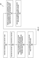
- FIG. 4 illustrates a flowchart for the Method 400.
- the Method 400 may be performed using the machining system 10, as described herein.
- the controller 18 may be used to execute or control one or more steps of the Method 400.
- the processor 46 may execute instructions stored in memory 48, thereby causing the controller 18 and/or its processor 46 to execute or otherwise control one or more steps of the Method 400 using the machining assembly 12, the rotary table 14, and/or the dimensional measurement assembly 16.
- the Method 400 is not limited to use with the machining system 10 described herein.
- Method 400 is not required to be performed in the specific sequence in which they are discussed below and, in various embodiments, the steps of Method 400 may be performed separately or simultaneously. Further, it should be understood that not all of the steps of the method 400, discussed below, may be required unless otherwise described herein.
- Step 402 includes positioning the workpiece 1000 on the rotatable platform 28 of the rotary table 14.
- FIG. 5 diagrammatically illustrates a side view of the workpiece 1000 positioned on the rotary table 14 (e.g., the rotatable platform 28).
- Step 402 may further include mounting or otherwise securing the workpiece 1000 on the rotatable platform, for example, using fasteners (e.g., mechanical fasteners) and/or other mounting hardware.
- fasteners e.g., mechanical fasteners
- the workpiece 1000 With the workpiece 1000 positioned on the rotary table 14 (e.g., the rotatable platform 28), the workpiece 1000 may have an eccentric or otherwise imperfect (e.g., off center) orientation relative to the rotational axis 30 as shown, for example, in FIG. 5 .
- the workpiece 1000 of FIG. 5 has a centerline axis 1002.
- the centerline axis 1002 may be understood to be colinear with the rotational axis 30.
- the centerline axis 1002 may, for example, be skewed, slanted, and/or radially offset relative to the rotational axis 30.
- Step 404 may optionally include positioning the rotary table 14 (e.g., the rotatable platform 28) in an initial (e.g., default) circumferential position.
- step 404 may include rotating the rotatable platform 28 from a current circumferential position to the initial circumferential position.
- Step 406 includes orienting the workpiece 1000 and the rotary table 14 relative to one or more coordinate systems (e.g., cartesian coordinate systems) used by the controller 18 to control functions of the machining system 10 and its components using the CNC instructions.
- the coordinate systems may include, but are not limited to, a machine coordinate system (MCS) for the machining assembly 12, a rotation coordinate system (PCS) for the rotary table 14, and/or a part coordinate system (PCS) for the workpiece 1000 (see FIGS. 1-3 ).
- MCS machine coordinate system
- PCS rotation coordinate system
- PCS part coordinate system
- Each of the coordinate systems may represent a reference frame for the workpiece 1000, the machining assembly 12, the rotary table 14, and/or the dimensional measurement assembly 16. As shown in FIG.
- the MCS may be oriented relative to a machine origin 50 (e.g., a position) at (e.g., on, adjacent, or proximate) the machining assembly 12.
- the MCS may be used as a global coordinate system for the machining system 10.
- positions and orientations of the workpiece 1000 e.g., expressed in the PCS
- the rotary table 14 e.g., expressed in the PCS
- step 406 includes identifying one or more points 52 (e.g., surface positions) on the workpiece 1000 using the dimensional measurement assembly 16 to orient the workpiece 1000 relative to the machining system 10 (e.g., relative to the MCS; see FIG. 1 ).
- the controller 18 may control the positioning system 36 to position the touch probe 34 to contact surfaces 1004 of the workpiece 1000 at the points 52 (see FIG. 3 ) with the rotatable platform 28 in the initial circumferential position.
- the controller 18 may determine a position (e.g., a geometric origin for the workpiece 1000) of the respective one of the points 52.
- the position may be represented, for example, by an x, y, and z position of the respective one of the points 52 relative to the MCS.
- the controller 18 may further determine an initial orientation 54A of each of the points 52 at the respective position.
- the initial orientation 54A may be orthogonal or substantially orthogonal to the surface 1004 at the position.
- the dimensional measurement assembly 16 may be used, for example to identify the points 52 at the axial and radial sides of the workpiece 1000 relative to the centerline axis 1002. Using the identified points 52 and predetermined dimensions of the workpiece 1000 (e.g., a three-dimensional (3D) model stored in the memory 48), the controller 18 may orient the workpiece 1000.
- 3D three-dimensional
- the controller 18 may apply a best-fit analysis using the identified points 52 and the predetermined dimensions of the workpiece 1000 to orient the workpiece (e.g., relative to the PCS). Subsequent to identification of the plurality of points 52 on the workpiece 1000 using the dimensional measurement assembly 16, as discussed above for step 406, no further dimensional measurement of the workpiece 1000 (e.g., using the dimensional measurement assembly 16) may be required for machining the workpiece 1000 in accordance with the present disclosure method 400.
- Step 406 includes, for one, more than one, or each of the points 52, determining (e.g., with the controller 18) an initial machine-workpiece vector V MW-A and an initial rotation-workpiece vector V RW-A in the MCS.
- the initial machine-workpiece vector V MW-A extends between and to the machine origin 50 and the position of the respective one of the points 52.
- the initial machine-workpiece vector V MW-A is determined using the position of the respective one of the points 52 identified using the dimensional measurement assembly 16.
- the initial rotation-workpiece vector V RW-A extends between and to a rotation origin 56 and the position of the respective one of the points 52.
- the rotation origin 56 is a point on the rotational axis 30.
- the initial rotation-workpiece vector V RW-A may be calculated by the controller 18 using a machine-rotation vector V MR and the machine-workpiece vector V MW-A .
- the machine-rotation vector V MR extends between and to the machine origin 50 and the rotation origin 56 of the rotational axis 30.
- the position of the rotation origin 56, the orientation of the rotational axis 30, and the machine-rotation vector V MR may be predetermined values (e.g., experimentally determined values for the machining system 10) expressed relative to the MCS and stored (e.g., in the memory 48).
- step 408 includes rotating the workpiece 1000 with the rotary table 14 (e.g., the rotatable platform 28) to position the workpiece 1000 relative to the machining assembly 12 for a machining operation.
- FIG. 7 diagrammatically illustrates a top view of the workpiece 1000 depicting rotation of the workpiece 1000 about the rotational axis 30.
- FIG. 8 diagrammatically illustrates one of the points 52 on the workpiece 1000 before and after rotation of the workpiece 1000.
- the controller 18 may identify a rotation angle ⁇ (e.g., from the CNC instructions for the workpiece 1000) to align a circumferential position of the workpiece 1000 with the machining assembly 12 to form a geometric feature (e.g., a slot) at the circumferential position of the workpiece 1000.
- the controller 18 may control the rotary table 14 to rotate the workpiece 1000 by an amount equal to or substantially equal to the rotation angle ⁇ to position the workpiece 1000 relative to the machining assembly 12.
- the controller 18 may control rotation of the workpiece 1000 from the initial circumferential position (see step 404) to a circumferential position of a first machining process for the workpiece 1000 or from a circumferential position of a completed machining process to a new circumferential position for a next sequential machining process.
- Step 410 includes updating a coordinate system (e.g., the PCS) for the workpiece 1000 for the change in workpiece 1000 position subsequent to rotating the workpiece 1000 by the rotation angle ⁇ (see step 408). Updating the coordinate system includes determining (e.g., with the controller 18) a new orientation and a new position for the workpiece 1000 subsequent to rotating the workpiece 1000 by the rotation angle ⁇ .
- a coordinate system e.g., the PCS
- Updating the coordinate system includes determining (e.g., with the controller 18) a new orientation and a new position for the workpiece 1000 subsequent to rotating the workpiece 1000 by the rotation angle ⁇ .
- Determining the new orientation for the workpiece 1000 includes determining, for one, more than one, or each of the points 52, a new orientation 54B in the coordinate system (e.g., the PCS) subsequent to rotating the workpiece 1000 by the rotation angle ⁇ .
- the controller 18 may calculate the new orientation 54B for one of the points 52 by rotating the initial orientation 54A for the respective one of the points 52 about the rotational axis 30, for example, using Rodrigues' rotational formula or another suitable method for calculating the new orientation 54A.
- the new orientation 54B subsequent to rotation by the rotation angle ⁇ may be identified using the following equation [2], where the new orientation 54B may be expressed using P' x , P' y , P' z and the rotation axis 30 may be expressed using n x , n y , n z :
- P x ′ cos ⁇ + P x 2 1 ⁇ cos ⁇ n x + P x P y 1 ⁇ cos ⁇ ⁇ P z sin ⁇ n y + P y sin ⁇ + P x P z 1 ⁇ cos ⁇ n z
- Determining the new position for the workpiece 1000 includes determining, for one, more than one, or each of the points 52, a new position 58 in the coordinate system (e.g., the PCS) subsequent to rotating the workpiece 1000 by the rotation angle ⁇ .
- the controller 18 may calculate the new position 58 for one of the points 52 by rotating the initial rotation-workpiece vector V RW-A about the rotational axis 30 to determine a new rotation-workpiece vector V RW-B for example, using Rodrigues' rotational formula or another suitable method for determining the new rotation-workpiece vector V RW-B such as, but not limited to, Equation [2] above.
- the new rotation-workpiece vector V RW-B may be used to calculate the new position 58 in the MCS by determining a new machine-workpiece vector V MW-B .
- the new rotation-workpiece vector V RW-B may be calculated by the controller 18 using machine-rotation vector V MR and the machine-workpiece vector V MW-A .
- the controller 18 may update the position and the orientation of the workpiece 1000 for the PCS using the new orientation 54B and the new position 58 for each of the points 52.
- the controller 18 may optionally control the dimensional measurement assembly 16 to identify one or more points on the workpiece 1000 to validate the updated position and the updated orientation for the workpiece 1000 using measured (e.g., real) positions and orientations of the workpiece 1000.
- measured e.g., real
- Step 412 includes machining the workpiece 1000 with the machining assembly 12 subsequent to rotating the workpiece 1000 by the rotation angle ⁇ (see step 408) and updating the PCS for the change in the position of the workpiece 1000 (see step 410).
- the controller 18 may execute the CNC instructions using the updated PCS position and orientation of the workpiece 1000 to control the machining assembly 12 to machine the workpiece 1000 to form one or more geometric features of the workpiece 1000.
- the controller 18 may control the WEDM system 20 of FIG. 2 to form a geometric feature (e.g., a rotor blade slot) of the workpiece 1000.
- the wire 26 is continuously fed from the upper feed member 22 to the lower feed member 24.
- the motion of the wire 26 at (e.g., on, adjacent, or proximate) the workpiece 1000 generates sparks between the wire 26 and the workpiece 1000 as the wire is fed from the upper feed member 22 to the lower feed member 24, thereby allowing the WEDM system 20 to cut the workpiece 1000 as necessary to form geometric features of a machined component (e.g., a rotor disk for a bladed rotor).
- a machined component e.g., a rotor disk for a bladed rotor
- the steps 408, 410, and 412 may be repeated as necessary to machine the workpiece 1000 to form a machined component.
- the steps 408, 410, and 412 may be sequentially performed to machine the workpiece 1000 at a plurality of circumferential positions of the workpiece 1000.
- any one of these structures may describe the operations as a sequential process, many of the operations can be performed in parallel or concurrently.
- the order of the operations may be rearranged.
- a process may correspond to a method, a function, a procedure, a subroutine, a subprogram, etc.
Landscapes
- Engineering & Computer Science (AREA)
- Mechanical Engineering (AREA)
- Human Computer Interaction (AREA)
- Manufacturing & Machinery (AREA)
- Physics & Mathematics (AREA)
- General Physics & Mathematics (AREA)
- Automation & Control Theory (AREA)
- General Engineering & Computer Science (AREA)
- Numerical Control (AREA)
Abstract
A machining system (10) includes a machining assembly (12), a rotary table (14), a dimensional measurement assembly (16), and a controller (18). The controller (18) is configured to control the dimensional measurement assembly (16) to identify a first position and a first orientation (54A) for a point (52) on a surface (1004) of a workpiece (1000) with at least one dimensional measurement sensor (32), determine a first machine-workpiece vector (VMW-A ) and a first rotation-workpiece vector (V RW-A ) for the point (52), control the rotary table (14) to rotate the workpiece (1000) about a rotational axis (30) by a rotation angle (φ), calculate a second position (58) and a second orientation (54B) for the point (52) subsequent to rotating the workpiece (1000) by rotating the first orientation (54A) about the rotational axis (30) by the rotation angle (φ) to calculate the second orientation (54B), rotating the first rotation-workpiece vector (VRW-A ) about the rotational axis (30) by the rotation angle (φ) to calculate a second rotation-workpiece vector (VRW-B ), and determining a second machine-workpiece vector (VMW-B ) using the second rotation-workpiece vector (VRW-B ) to calculate the second position (58), update a workpiece position and a workpiece orientation in a part coordinate system (PCS) for the workpiece (1000) using the second position (58) and the second orientation (54B), and control the machining assembly (12) to machine the workpiece (1000) using the updated workpiece position and the updated workpiece orientation.
Description
- This disclosure relates generally to machining systems methods and, more particularly, to systems and methods for machining a workpiece installed on a rotary table.
- Machining systems may be used to accomplish one or more workpiece machining (e.g., drilling, grinding, milling, polishing, three-dimensional (3D) printing, etc.) operations for component manufacture. Various machining systems and methods are known in the art. While these known systems and methods have various advantages, there is still room in the art for improvement.
- It should be understood that any or all of the features or embodiments described herein can be used or combined in any combination with each and every other feature or embodiment described herein unless expressly noted otherwise.
- According to an aspect of the present invention, a machining system for machining a workpiece to form an aircraft engine component includes a machining assembly, a rotary table, a dimensional measurement assembly, and a controller. The machining assembly is configured for machining the workpiece. The rotary table is configured to rotate the workpiece about a rotational axis. The dimensional measurement assembly includes at least one dimensional measurement sensor. The controller includes a processor in communication with a non-transitory memory storing instructions, which instructions when executed by the processor, cause the processor to control the dimensional measurement assembly to identify a first position and a first orientation for a point on a surface of the workpiece with the at least one dimensional measurement sensor, determine a first machine-workpiece vector and a first rotation-workpiece vector for the point, control the rotary table to rotate the workpiece about the rotational axis by a rotation angle, calculate a second position and a second orientation for the point subsequent to rotating the workpiece by rotating the first orientation about the rotational axis by the rotation angle to calculate the second orientation, rotating the first rotation-workpiece vector about the rotational axis by the rotation angle to calculate a second rotation-workpiece vector, and determining a second machine-workpiece vector using the second rotation-workpiece vector to calculate the second position, update a workpiece position and a workpiece orientation in a coordinate system for the workpiece using the second position and the second orientation for the point, and control the machining assembly to machine the workpiece using the updated workpiece position and updated workpiece orientation.
- In an embodiment of the above, the first machine-workpiece vector may extend between and to a machine origin at the machining assembly and the first position and the second machine-workpiece vector may extend between and to the machine origin and the second position.
- In an embodiment according to any of the previous embodiments, the first rotation-workpiece vector may extend between and to a rotation origin at the rotational axis and the first position and the second rotation-workpiece vector may extend between and to the rotation origin and the second position.
- In an embodiment according to any of the previous embodiments, determining the first rotation-workpiece vector may include determining the first rotation-workpiece vector using the first machine-workpiece vector and a machine-rotation vector. The machine-rotation vector may extend between and to a machine origin at the machining assembly and a rotation origin at the rotational axis.
- In an embodiment according to any of the previous embodiments, the machining assembly may include a wire electric discharge machining (WEDM) system.
- In an embodiment according to any of the previous embodiments, the at least one dimensional measurement sensor may include a touch probe.
- In an embodiment according to any of the previous embodiments, the instructions, when executed by the processor, may further cause the processor to control the rotary table to hold the workpiece stationary while calculating the second position and the second orientation for each point of the at least one point, updating the workpiece position and the workpiece orientation in the PCS, and controlling the machining assembly to machine the workpiece using the updated workpiece position and updated workpiece orientation.
- According to another aspect of the present invention, a method for machining a workpiece installed on a rotary table to form an aircraft engine component includes positioning the workpiece on the rotary table, identifying a first position and a first orientation for at least one point on one or more surfaces of the workpiece using at least one dimensional measurement sensor, determining a first machine-workpiece vector and a first rotation-workpiece vector for the at least one point, and machining the workpiece at a plurality of circumferential positions by, for each circumferential position of the plurality of circumferential positions, sequentially: rotating the workpiece with the rotary table about a rotational axis by a rotation angle to one circumferential position of the plurality of circumferential positions, calculating a second position and a second orientation for the at least one point by rotating the first orientation about the rotational axis by the rotation angle to calculate the second orientation, rotating the first rotation-workpiece vector about the rotational axis by the rotation angle to calculate a second rotation-workpiece vector, and determining a second machine-workpiece vector using the second rotation-workpiece vector to calculate the second position, updating a workpiece position and a workpiece orientation for the workpiece using the second position and the second orientation for the at least one point, and machining the workpiece at the one circumferential position with a machining assembly using the updated workpiece position and updated workpiece orientation.
- In an embodiment of the above, positioning the workpiece on the rotary table may include positioning the workpiece with a centerline axis of the workpiece offset from the rotational axis.
- In an embodiment according to any of the previous embodiments, the first machine-workpiece vector may extend between and to a machine origin at the machining assembly and the first position and the second machine-workpiece vector may extend between and to the machine origin and the second position.
- In an embodiment according to any of the previous embodiments, the first rotation-workpiece vector may extend between and to a rotation origin at the rotational axis and the first position and the second rotation-workpiece vector may extend between and to the rotation origin and the second position.
- In an embodiment according to any of the previous embodiments, determining the first rotation-workpiece vector may include determining the first rotation-workpiece vector using the first machine-workpiece vector and a machine-rotation vector. The machine-rotation vector may extend between and to a machine origin at the machining assembly and a rotation origin at the rotational axis.
- In an embodiment according to any of the previous embodiments, the method may further include positioning the rotary table in a predetermined rotational position prior to identifying the first position and the first orientation.
- In an embodiment according to any of the previous embodiments, machining the workpiece at the one circumferential position may include forming a slot in the workpiece at the one circumferential position with the machining assembly.
- According to another aspect of the present invention, a machining system for machining a workpiece to form an aircraft engine component includes a machining assembly, a rotary table, the workpiece, a dimensional measurement assembly, and a controller. The rotary table includes a rotatable platform configured for rotation about a rotational axis. The workpiece is positioned on the rotatable platform. The workpiece has a centerline axis. The workpiece is positioned on the rotary table with the centerline axis offset from the rotational axis. The dimensional measurement assembly includes a touch probe. The controller includes a processor in communication with a non-transitory memory storing instructions including computer numerical control (CNC) instructions, which instructions when executed by the processor, cause the processor to control the dimensional measurement assembly to identify a first position and a first orientation for at least one point on one or more surfaces of the workpiece with the touch probe, determine a first machine-workpiece vector and a first rotation-workpiece vector for the at least one point, and machine the workpiece at a plurality of circumferential positions by, for each circumferential position of the plurality of circumferential positions, sequentially controlling the rotary table to rotate the workpiece about the rotational axis by a rotation angle to one circumferential position of the plurality of circumferential positions, determining a second position and a second orientation for each point of the at least one point with the workpiece in the one circumferential position, updating a workpiece position and a workpiece orientation in a coordinate system for the workpiece using the second position and the second orientation, and controlling the machining assembly to machine the workpiece using the updated workpiece position and updated workpiece orientation.
- In an embodiment of the above, the centerline axis may be skewed relative to the rotational axis.
- In an embodiment according to any of the previous embodiments, controlling the machining assembly to machine the workpiece may include controlling the machining assembly to machine the workpiece at the one circumferential position by forming a slot in the workpiece at the one circumferential position with the machining assembly.
- In an embodiment according to any of the previous embodiments, determining the second position and the second orientation for each point of the at least one point may include determining the second position and the second orientation for the at least one point without identifying the second position and the second orientation using the touch probe.
- In an embodiment according to any of the previous embodiments, the machining assembly may include a wire electric discharge machining (WEDM) system. The WEDM system may include an upper feed member and a lower feed member configured for translation and rotation relative to the workpiece. The upper feed member and the lower feed member may be configured to machine the workpiece using a wire fed between the upper feed member and the lower feed member.
- In an embodiment according to any of the previous embodiments, the first position may be different than the second position and the first orientation may be different than the second orientation for each point of the at least one point.
- The present disclosure, and all its aspects, embodiments and advantages associated therewith will become more readily apparent in view of the detailed description provided below, including the accompanying drawings.
-
-
FIG. 1 diagrammatically illustrates a machining system, in accordance with one or more embodiments of the present disclosure. -
FIG. 2 illustrates a perspective view of a machining assembly and a rotary table for the machining system ofFIG. 1 , in accordance with one or more embodiments of the present disclosure. -
FIG. 3 diagrammatically illustrates a dimensional measurement assembly for the machining system ofFIG. 1 , in accordance with one or more embodiments of the present disclosure. -
FIG. 4 illustrates a block diagram depicting a method for machining a workpiece installed on a rotary table, in accordance with one or more embodiments of the present disclosure. -
FIG. 5 diagrammatically illustrates a side view of a workpiece positioned on the rotary table, in accordance with one or more embodiments of the present disclosure. -
FIG. 6 diagrammatically illustrates the workpiece relative to a rotational axis of the rotary table, in accordance with one or more embodiments of the present disclosure. -
FIG. 7 diagrammatically illustrates a top view of the workpiece depicting a rotation process for the workpiece, in accordance with one or more embodiments of the present disclosure. -
FIG. 8 diagrammatically illustrates the workpiece relative to the rotational axis of the rotary table following the rotation process for the workpiece, in accordance with one or more embodiments of the present disclosure. -
FIG. 1 diagrammatically illustrates amachining system 10. Themachining system 10 ofFIG. 1 is a computer numeric control (CNC) machining system configured for automated control of one or more machining tools for use in the machining of aworkpiece 1000 to form a machined component. As an example, theworkpiece 1000 ofFIG. 1 may be machined to form a disk which may form a portion of a bladed rotor (e.g., a bladed turbine rotor, a bladed fan rotor, etc.) of a gas turbine engine for an aircraft propulsion system. The present disclosure, however, is not limited to anyparticular workpiece 1000 or machined component type, configuration, or material. Themachining system 10 ofFIG. 1 includes amachining assembly 12, a rotary table 14, adimensional measurement assembly 16, and acontroller 18. -
FIG. 2 diagrammatically illustrates a partial cutaway view of themachining assembly 12 and the rotary table 14 relative to theworkpiece 1000. Themachining assembly 12 ofFIG. 2 includes a wire electric discharge machining (WEDM)system 20. The WEDMsystem 20 ofFIG. 2 includes anupper feed member 22 and alower feed member 24 configured, for example, to continuously feed awire 26 from theupper feed member 22 to thelower feed member 24 during a machining operation for theworkpiece 1000. The WEDM system 20 (e.g., theupper feed member 22 and the lower feed member 24) may be configured to translate along and/or rotate about one or more of an x-axis, a y-axis, and a z-axis. The presentdisclosure machining assembly 12, however, is not limited to WEDM systems and may alternatively include other configurations of machining (e.g., milling, drilling, grinding, turning, cutting, boring, etc.) systems and tools. - The rotary table 14 includes a
rotatable platform 28. Therotatable platform 28 is rotatable about arotational axis 30 of the rotary table 14. For ease of description, therotational axis 30 ofFIG. 2 may be understood to be oriented along the Z-axis, however, the present disclosure is not limited to this particular orientation of therotational axis 30. Therotatable platform 28 is configured to securely retain theworkpiece 1000 and to rotate theworkpiece 1000 about therotational axis 30 to position theworkpiece 1000 relative to themachining assembly 12. Therotatable platform 28 may include fasteners (e.g., mechanical fasteners) and/or other mounting hardware for securely mounting or otherwise retaining theworkpiece 1000 on therotatable platform 28. -
FIG. 3 diagrammatically illustrates a side view of thedimensional measurement assembly 16 and the rotary table 14 relative to theworkpiece 1000. Thedimensional measurement assembly 16 includes one or moredimensional measurement sensors 32. Thedimensional measurement sensor 32 ofFIG. 3 is configured as atouch probe 34. Thetouch probe 34 ofFIG. 3 is configured to identify positions of the workpiece 1000 (e.g., workpiece surface positions) relative to a three-dimensional coordinate space based on physical contact between thetouch probe 34 and theworkpiece 1000. For example, thetouch probe 34 may be used to measure the shape, size, curvature, and other geometric features of theworkpiece 1000 by sensing (e.g., contacting) discrete points on surfaces of theworkpiece 1000. Thedimensional measurement sensors 32, however, are not limited to touch probes. For example, thedimensional measurement sensors 32 may additionally or alternatively include any dimensional measurement sensor or device configured to measure geometric characteristics of theworkpiece 1000 such as, but not limited to, coordinate-measuring machines (CMMs), contact scanning probes, non-contact probes, laser trackers, machine vision systems, optical scanners, optical comparators, and the like. - The
dimensional measurement assembly 16 may include apositioning system 36 configured to position thedimensional measurement sensors 32 relative to theworkpiece 1000. For example, thepositioning system 36 ofFIG. 3 includes arobotic arm 38 configured to position thetouch probe 34. Therobotic arm 38 includes abase end 40, adistal end 42, and one or moremovable joints 44 between thebase end 40 and thedistal end 42. Each movable joint 44 may be moved or otherwise controlled, for example, by an independent servo motor or other actuator. Thedistal end 42 may be connected to thetouch probe 34. Therobotic arm 38 is configured move thetouch probe 34 relative to theworkpiece 1000 and/or to one or more other components of themachining system 10. For example, therobotic arm 38 may be configured to move thetouch probe 34 along an x-axis, a y-axis, and a z-axis, as well as to rotate thetouch probe 34 relative to the x-axis, the y-axis, and the z-axis (e.g., pitch, yaw, and roll). - Referring again to
FIG. 1 , thecontroller 18 is connected in signal communication with themachining assembly 12, the rotary table 14, and thedimensional measurement assembly 16. Thecontroller 18 includes aprocessor 46 andmemory 48. Thememory 48 is connected in signal communication with theprocessor 46. Theprocessor 46 may include any type of computing device, computational circuit, or any type of process or processing circuit capable of executing a series of instructions that are stored in thememory 48, thereby causing theprocessor 46 to perform or control one or more steps or other processes. Theprocessor 46 may include multiple processors and/or multicore CPUs and may include any type of processor, such as a microprocessor, digital signal processor, co-processors, a micro-controller, a microcomputer, a central processing unit, a field programmable gate array, a programmable logic device, a state machine, logic circuitry, analog circuitry, digital circuitry, etc., and any combination thereof. The instructions stored inmemory 48 may represent one or more algorithms for controlling operations of themachining assembly 12, the rotary table 14, and thedimensional measurement assembly 16, and the stored instructions are not limited to any particular form (e.g., program files, system data, buffers, drivers, utilities, system programs, etc.) provided they can be executed by theprocessor 46. The instructions stored inmemory 48 may be in the form of a CNC programming language (e.g., G-code, M-code, etc.), or another suitable programming language which can be executed by thecontroller 18 and/or itsprocessor 46. For example, the CNC programming language instructions may be executed by theprocessor 46, for example, to control positioning, movement speed, and a tool path for theWEDM system 20 and/or a rotational position of the rotary table 14 e.g., the rotatable platform 28). The instructions stored inmemory 48 may be generated by computer-aided design (CAD) or computer-aided manufacturing (CAM) software, whereby the physical dimensions of a particular workpiece (e.g., the workpiece 1000) may be translated into instructions (e.g., CNC) instructions). Thememory 48 may be a non-transitory computer readable storage medium configured to store instructions that when executed by one or more processors, cause the one or more processors to perform or cause the performance of certain functions. Thememory 48 may be a single memory device or a plurality of memory devices. A memory device may include a storage area network, network attached storage, as well a disk drive, a read-only memory, random access memory, volatile memory, non-volatile memory, static memory, dynamic memory, flash memory, cache memory, and/or any device that stores digital information. One skilled in the art will appreciate, based on a review of this disclosure, that the implementation of thecontroller 18 may be achieved via the use of hardware, software, firmware, or any combination thereof. Thecontroller 18 may also include input and output devices (e.g., keyboards, buttons, switches, touch screens, video monitors, sensor readouts, data ports, etc.) that enable the operator to input instructions, receive data, etc. - During a machining operation for the
workpiece 1000, mobility of the machining assembly 12 (e.g., the WEDM system 20) relative to theworkpiece 1000 may be limited. For example, theWEDM system 20 may be configured to machine a rotor blade slot (e.g., a firtree slot) in theworkpiece 1000 at a circumferential position of theworkpiece 1000. With theworkpiece 1000 stationary, theWEDM system 20 may not be configured to move to a second circumferential position of theworkpiece 1000 to form a second rotor blade slot. The rotary table 14 may rotate theworkpiece 1000 about therotational axis 30 to position the second circumferential position of theworkpiece 1000 at (e.g., on, adjacent, or proximate) theWEDM system 20 for machining the second rotor blade slot. However, in at least some cases, theworkpiece 1000 may be positioned on (e.g., retained by) the rotary table 14 with eccentricity or otherwise imperfect (e.g., off center) orientation relative to therotational axis 30. Accordingly, rotation of theworkpiece 1000 by the rotary table 14 may cause machining surfaces of theworkpiece 1000 to be positioned outside of an expected position range and inconsistent with the CNC instructions executed by thecontroller 18 to control machining of theworkpiece 1000 with theWEDM system 20. For high-precision machining operations, such as those discussed above for forming gas turbine engine rotor disks, this eccentricity or imperfect orientation of theworkpiece 1000 on the rotary table 14 may cause the machinedworkpiece 1000 to fail one or more dimensional tolerance requirements. We have found that eccentricity or imperfect orientation of the workpiece on the rotary table 14 may be prevented or mitigated by using complex fixturing to facilitate precise positioning of theworkpiece 1000 on the rotary table 14 and/or by identifying positions of the workpiece 1000 (e.g., using the touch probe 34) after each movement of the rotary table 14 to rotate theworkpiece 1000. However, these solutions may add considerable time, complexity, and expense to a machining process for theworkpiece 1000. - Referring to
FIG. 4 , amethod 400 for machining a workpiece installed on a rotary table is provided.FIG. 4 illustrates a flowchart for theMethod 400. TheMethod 400 may be performed using themachining system 10, as described herein. Thecontroller 18 may be used to execute or control one or more steps of theMethod 400. For example, theprocessor 46 may execute instructions stored inmemory 48, thereby causing thecontroller 18 and/or itsprocessor 46 to execute or otherwise control one or more steps of theMethod 400 using themachining assembly 12, the rotary table 14, and/or thedimensional measurement assembly 16. However, it should be understood that theMethod 400 is not limited to use with themachining system 10 described herein. Unless otherwise noted herein, it should be understood that the steps ofMethod 400 are not required to be performed in the specific sequence in which they are discussed below and, in various embodiments, the steps ofMethod 400 may be performed separately or simultaneously. Further, it should be understood that not all of the steps of themethod 400, discussed below, may be required unless otherwise described herein. - Step 402 includes positioning the
workpiece 1000 on therotatable platform 28 of the rotary table 14.FIG. 5 diagrammatically illustrates a side view of theworkpiece 1000 positioned on the rotary table 14 (e.g., the rotatable platform 28). Step 402 may further include mounting or otherwise securing theworkpiece 1000 on the rotatable platform, for example, using fasteners (e.g., mechanical fasteners) and/or other mounting hardware. With theworkpiece 1000 positioned on the rotary table 14 (e.g., the rotatable platform 28), theworkpiece 1000 may have an eccentric or otherwise imperfect (e.g., off center) orientation relative to therotational axis 30 as shown, for example, inFIG. 5 . The imperfect orientation of theworkpiece 1000 ofFIG. 5 and subsequent figures (seeFIG. 7 ) relative to therotational axis 30 may be understood to be exaggerated for the purpose of clarifying aspects of the present disclosure. Theworkpiece 1000 ofFIG. 5 has acenterline axis 1002. In a perfectly aligned condition of theworkpiece 1000, thecenterline axis 1002 may be understood to be colinear with therotational axis 30. With theworkpiece 1000 having an imperfect orientation relative to therotational axis 30, as shown inFIG. 5 , thecenterline axis 1002 may, for example, be skewed, slanted, and/or radially offset relative to therotational axis 30. - Step 404 may optionally include positioning the rotary table 14 (e.g., the rotatable platform 28) in an initial (e.g., default) circumferential position. For example, step 404 may include rotating the
rotatable platform 28 from a current circumferential position to the initial circumferential position. - Step 406 includes orienting the
workpiece 1000 and the rotary table 14 relative to one or more coordinate systems (e.g., cartesian coordinate systems) used by thecontroller 18 to control functions of themachining system 10 and its components using the CNC instructions. The coordinate systems may include, but are not limited to, a machine coordinate system (MCS) for themachining assembly 12, a rotation coordinate system (PCS) for the rotary table 14, and/or a part coordinate system (PCS) for the workpiece 1000 (seeFIGS. 1-3 ). Each of the coordinate systems may represent a reference frame for theworkpiece 1000, themachining assembly 12, the rotary table 14, and/or thedimensional measurement assembly 16. As shown inFIG. 6 , for example, the MCS may be oriented relative to a machine origin 50 (e.g., a position) at (e.g., on, adjacent, or proximate) themachining assembly 12. The MCS may be used as a global coordinate system for themachining system 10. For example, in addition to themachining assembly 12, positions and orientations of the workpiece 1000 (e.g., expressed in the PCS) and the rotary table 14 (e.g., expressed in the PCS) may additionally be identified and expressed by thecontroller 18 using the MCS, or vice versa. - Referring to
FIGS. 5 and6 ,step 406 includes identifying one or more points 52 (e.g., surface positions) on theworkpiece 1000 using thedimensional measurement assembly 16 to orient theworkpiece 1000 relative to the machining system 10 (e.g., relative to the MCS; seeFIG. 1 ). For example, thecontroller 18 may control thepositioning system 36 to position thetouch probe 34 to contactsurfaces 1004 of theworkpiece 1000 at the points 52 (seeFIG. 3 ) with therotatable platform 28 in the initial circumferential position. For each of thepoints 52, thecontroller 18 may determine a position (e.g., a geometric origin for the workpiece 1000) of the respective one of thepoints 52. The position may be represented, for example, by an x, y, and z position of the respective one of thepoints 52 relative to the MCS. Thecontroller 18 may further determine aninitial orientation 54A of each of thepoints 52 at the respective position. Theinitial orientation 54A may be orthogonal or substantially orthogonal to thesurface 1004 at the position. Thedimensional measurement assembly 16 may be used, for example to identify thepoints 52 at the axial and radial sides of theworkpiece 1000 relative to thecenterline axis 1002. Using the identified points 52 and predetermined dimensions of the workpiece 1000 (e.g., a three-dimensional (3D) model stored in the memory 48), thecontroller 18 may orient theworkpiece 1000. For example, thecontroller 18 may apply a best-fit analysis using the identified points 52 and the predetermined dimensions of theworkpiece 1000 to orient the workpiece (e.g., relative to the PCS). Subsequent to identification of the plurality ofpoints 52 on theworkpiece 1000 using thedimensional measurement assembly 16, as discussed above forstep 406, no further dimensional measurement of the workpiece 1000 (e.g., using the dimensional measurement assembly 16) may be required for machining theworkpiece 1000 in accordance with thepresent disclosure method 400. - Step 406 includes, for one, more than one, or each of the
points 52, determining (e.g., with the controller 18) an initial machine-workpiece vector VMW-A and an initial rotation-workpiece vector VRW-A in the MCS. The initial machine-workpiece vector VMW-A extends between and to themachine origin 50 and the position of the respective one of thepoints 52. The initial machine-workpiece vector VMW-A is determined using the position of the respective one of thepoints 52 identified using thedimensional measurement assembly 16. The initial rotation-workpiece vector VRW-A extends between and to arotation origin 56 and the position of the respective one of thepoints 52. Therotation origin 56 is a point on therotational axis 30. The initial rotation-workpiece vector VRW-A may be calculated by thecontroller 18 using a machine-rotation vector VMR and the machine-workpiece vector VMW-A . The machine-rotation vector VMR extends between and to themachine origin 50 and therotation origin 56 of therotational axis 30. The position of therotation origin 56, the orientation of therotational axis 30, and the machine-rotation vector VMR may be predetermined values (e.g., experimentally determined values for the machining system 10) expressed relative to the MCS and stored (e.g., in the memory 48). A value of the initial rotation-workpiece vector VRW-A may be calculated using the following equation [1]:
- Referring to
FIGS. 7 and 8 ,step 408 includes rotating theworkpiece 1000 with the rotary table 14 (e.g., the rotatable platform 28) to position theworkpiece 1000 relative to themachining assembly 12 for a machining operation.FIG. 7 diagrammatically illustrates a top view of theworkpiece 1000 depicting rotation of theworkpiece 1000 about therotational axis 30.FIG. 8 diagrammatically illustrates one of thepoints 52 on theworkpiece 1000 before and after rotation of theworkpiece 1000. Thecontroller 18 may identify a rotation angle φ (e.g., from the CNC instructions for the workpiece 1000) to align a circumferential position of theworkpiece 1000 with themachining assembly 12 to form a geometric feature (e.g., a slot) at the circumferential position of theworkpiece 1000. Thecontroller 18 may control the rotary table 14 to rotate theworkpiece 1000 by an amount equal to or substantially equal to the rotation angle φ to position theworkpiece 1000 relative to themachining assembly 12. Thecontroller 18 may control rotation of theworkpiece 1000 from the initial circumferential position (see step 404) to a circumferential position of a first machining process for theworkpiece 1000 or from a circumferential position of a completed machining process to a new circumferential position for a next sequential machining process. - Step 410 includes updating a coordinate system (e.g., the PCS) for the
workpiece 1000 for the change inworkpiece 1000 position subsequent to rotating theworkpiece 1000 by the rotation angle φ (see step 408). Updating the coordinate system includes determining (e.g., with the controller 18) a new orientation and a new position for theworkpiece 1000 subsequent to rotating theworkpiece 1000 by the rotation angle φ. - Determining the new orientation for the
workpiece 1000 includes determining, for one, more than one, or each of thepoints 52, anew orientation 54B in the coordinate system (e.g., the PCS) subsequent to rotating theworkpiece 1000 by the rotation angle φ. Thecontroller 18 may calculate thenew orientation 54B for one of thepoints 52 by rotating theinitial orientation 54A for the respective one of thepoints 52 about therotational axis 30, for example, using Rodrigues' rotational formula or another suitable method for calculating thenew orientation 54A. For example, thenew orientation 54B subsequent to rotation by the rotation angle φ may be identified using the following equation [2], where thenew orientation 54B may be expressed using P'x, P'y, P'z and therotation axis 30 may be expressed using nx, ny, nz:


- Determining the new position for the
workpiece 1000 includes determining, for one, more than one, or each of thepoints 52, anew position 58 in the coordinate system (e.g., the PCS) subsequent to rotating theworkpiece 1000 by the rotation angle φ. Thecontroller 18 may calculate thenew position 58 for one of thepoints 52 by rotating the initial rotation-workpiece vector VRW-A about therotational axis 30 to determine a new rotation-workpiece vector VRW-B for example, using Rodrigues' rotational formula or another suitable method for determining the new rotation-workpiece vector VRW-B such as, but not limited to, Equation [2] above. The new rotation-workpiece vector VRW-B may be used to calculate thenew position 58 in the MCS by determining a new machine-workpiece vector VMW-B. The new rotation-workpiece vector VRW-B may be calculated by thecontroller 18 using machine-rotation vector VMR and the machine-workpiece vector VMW-A. For example, a value of the rotation-workpiece vector VRW-A may be calculated using the following equation [3]:
- The
controller 18 may update the position and the orientation of theworkpiece 1000 for the PCS using thenew orientation 54B and thenew position 58 for each of thepoints 52. In some embodiments, thecontroller 18 may optionally control thedimensional measurement assembly 16 to identify one or more points on theworkpiece 1000 to validate the updated position and the updated orientation for theworkpiece 1000 using measured (e.g., real) positions and orientations of theworkpiece 1000. However, as previously discussed, subsequent to identification of the plurality ofpoints 52 on theworkpiece 1000 using thedimensional measurement assembly 16, no further dimensional measurement of the workpiece 1000 (e.g., using the dimensional measurement assembly 16) may be required for machining theworkpiece 1000 under thepresent disclosure method 400. - Step 412 includes machining the
workpiece 1000 with themachining assembly 12 subsequent to rotating theworkpiece 1000 by the rotation angle φ (see step 408) and updating the PCS for the change in the position of the workpiece 1000 (see step 410). Thecontroller 18 may execute the CNC instructions using the updated PCS position and orientation of theworkpiece 1000 to control themachining assembly 12 to machine theworkpiece 1000 to form one or more geometric features of theworkpiece 1000. For example, thecontroller 18 may control theWEDM system 20 ofFIG. 2 to form a geometric feature (e.g., a rotor blade slot) of theworkpiece 1000. In operation of theWEDM system 20 ofFIG. 2 , thewire 26 is continuously fed from theupper feed member 22 to thelower feed member 24. The motion of thewire 26 at (e.g., on, adjacent, or proximate) theworkpiece 1000 generates sparks between thewire 26 and theworkpiece 1000 as the wire is fed from theupper feed member 22 to thelower feed member 24, thereby allowing theWEDM system 20 to cut theworkpiece 1000 as necessary to form geometric features of a machined component (e.g., a rotor disk for a bladed rotor). - The
steps workpiece 1000 to form a machined component. For example, thesteps workpiece 1000 at a plurality of circumferential positions of theworkpiece 1000. - While the principles of the disclosure have been described above in connection with specific apparatuses and methods, it is to be clearly understood that this description is made only by way of example and not as limitation on the scope of the disclosure. Specific details are given in the above description to provide a thorough understanding of the embodiments. However, it is understood that the embodiments may be practiced without these specific details.
- It is noted that the embodiments may be described as a process which is depicted as a flowchart, a flow diagram, a block diagram, etc. Although any one of these structures may describe the operations as a sequential process, many of the operations can be performed in parallel or concurrently. In addition, the order of the operations may be rearranged. A process may correspond to a method, a function, a procedure, a subroutine, a subprogram, etc.
- The singular forms "a," "an," and "the" refer to one or more than one, unless the context clearly dictates otherwise. For example, the term "comprising a specimen" includes single or plural specimens and is considered equivalent to the phrase "comprising at least one specimen." The term "or" refers to a single element of stated alternative elements or a combination of two or more elements unless the context clearly indicates otherwise. As used herein, "comprises" means "includes." Thus, "comprising A or B," means "including A or B, or A and B," without excluding additional elements.
- It is noted that various connections are set forth between elements in the present description and drawings (the contents of which are included in this disclosure by way of reference). It is noted that these connections are general and, unless specified otherwise, may be direct or indirect and that this specification is not intended to be limiting in this respect. Any reference to attached, fixed, connected, or the like may include permanent, removable, temporary, partial, full and/or any other possible attachment option.
- No element, component, or method step in the present disclosure is intended to be dedicated to the public regardless of whether the element, component, or method step is explicitly recited in the claims. As used herein, the terms "comprise", "comprising", or any other variation thereof, are intended to cover a non-exclusive inclusion, such that a process, method, article, or apparatus that comprises a list of elements does not include only those elements but may include other elements not expressly listed or inherent to such process, method, article, or apparatus.
- While various inventive aspects, concepts and features of the disclosures may be described and illustrated herein as embodied in combination in the exemplary embodiments, these various aspects, concepts, and features may be used in many alternative embodiments, either individually or in various combinations and sub-combinations thereof. Unless expressly excluded herein all such combinations and sub-combinations are intended to be within the scope of the present application. Still further, while various alternative embodiments as to the various aspects, concepts, and features of the disclosures--such as alternative materials, structures, configurations, methods, devices, and components, and so on--may be described herein, such descriptions are not intended to be a complete or exhaustive list of available alternative embodiments, whether presently known or later developed. Those skilled in the art may readily adopt one or more of the inventive aspects, concepts, or features into additional embodiments and uses within the scope of the present application even if such embodiments are not expressly disclosed herein. For example, in the exemplary embodiments described above within the Detailed Description portion of the present specification, elements may be described as individual units and shown as independent of one another to facilitate the description. In alternative embodiments, such elements may be configured as combined elements.
Claims (15)
- A machining system (10) for machining a workpiece (1000) to form an aircraft engine component, the machining system (10) comprising:a machining assembly (12) configured for machining the workpiece (1000);a rotary table (14) configured to rotate the workpiece (1000) about a rotational axis (30);a dimensional measurement assembly (16) including at least one dimensional measurement sensor (32); anda controller (18) including a processor (46) in communication with a non-transitory memory (48) storing instructions, which instructions when executed by the processor (46), cause the processor (46) to:control the dimensional measurement assembly (16) to identify a first position and a first orientation (54A) for a point (52) on a surface (1004) of the workpiece (1000) with the at least one dimensional measurement sensor (32);determine a first machine-workpiece vector (VMW-A ) and a first rotation-workpiece vector (VRW-A ) for the point (52);control the rotary table (14) to rotate the workpiece (1000) about the rotational axis (30) by a rotation angle (φ);calculate a second position (58) and a second orientation (54B) for the point (52) subsequent to rotating the workpiece (1000) by rotating the first orientation (54A) about the rotational axis (30) by the rotation angle (φ) to calculate the second orientation (54B), rotating the first rotation-workpiece vector (VRW-A ) about the rotational axis (30) by the rotation angle (φ) to calculate a second rotation-workpiece vector (VRW-B ), and determining a second machine-workpiece vector (VMW-B ) using the second rotation-workpiece vector (VRW-B ) to calculate the second position (58);update a workpiece position and a workpiece orientation in a coordinate system (20) for the workpiece (1000) using the second position (58) and the second orientation (54B) for the point (52); andcontrol the machining assembly (12) to machine the workpiece (1000) using the updated workpiece position and the updated workpiece orientation.
- The machining system (10) of claim 1, wherein the first machine-workpiece vector (VMW-A ) extends between and to a machine origin (50) at the machining assembly (12) and the first position and the second machine-workpiece vector (VMW-B ) extends between and to the machine origin (50) and the second position (58).
- The machining system (10) of claim 1 or 2, wherein the first rotation-workpiece vector (VRW-A ) extends between and to a rotation origin (56) at the rotational axis (30) and the first position and the second rotation-workpiece vector (VRW-B ) extends between and to the rotation origin (56) and the second position (58).
- The machining system (10) of any preceding claim, wherein determining the first rotation-workpiece vector (VRW-A ) includes determining the first rotation-workpiece vector (VRW-A ) using the first machine-workpiece vector (VMW-A ) and a machine-rotation vector (VMR ), and the machine-rotation vector (VMR ) extends between and to a machine origin (50) at the machining assembly (12) and a or the rotation origin (56) at the rotational axis (30).
- The machining system (10) of any preceding claim, wherein the machining assembly (12) includes a wire electric discharge machining (WEDM) system (20).
- The machining system (10) of any preceding claim, wherein the at least one dimensional measurement sensor (32) includes a touch probe (34).
- The machining system (10) of any preceding claim, wherein the instructions, when executed by the processor (46), further cause the processor (46) to control the rotary table (14) to hold the workpiece (1000) stationary while calculating the second position (58) and the second orientation (54B) for each point of the at least one point (52), updating the workpiece position and the workpiece orientation in the coordinate system (20), and controlling the machining assembly (12) to machine the workpiece (1000) using the updated workpiece position and updated workpiece orientation.
- A method for machining a workpiece (1000) installed on a rotary table (14) to form an aircraft engine component, the method comprising:positioning the workpiece (1000) on the rotary table (14);identifying a first position and a first orientation (54A) for at least one point (52) on one or more surfaces (1004) of the workpiece (1000) using at least one dimensional measurement sensor (32);determining a first machine-workpiece vector (VMW-A ) and a first rotation-workpiece vector (VRW-A ) for the at least one point (52); andmachining the workpiece (1000) at a plurality of circumferential positions by, for each circumferential position of the plurality of circumferential positions, sequentially:rotating the workpiece (1000) with the rotary table (14) about a rotational axis (30) by a rotation angle (φ) to one circumferential position of the plurality of circumferential positions;calculating a second position (58) and a second orientation (54B) for the at least one point (52) by rotating the first orientation (54A) about the rotational axis (30) by the rotation angle (φ) to calculate the second orientation (54B), rotating the first rotation-workpiece vector (VRW-A ) about the rotational axis (30) by the rotation angle (φ) to calculate a second rotation-workpiece vector (VRW-B ), and determining a second machine-workpiece vector (VMW-B ) using the second rotation-workpiece vector (VRW-B ) to calculate the second position (58);updating a workpiece position and a workpiece orientation for the workpiece (1000) using the second position (58) and the second orientation (54B) for the at least one point (52); andmachining the workpiece (1000) at the one circumferential position with a machining assembly (12) using the updated workpiece position and updated workpiece orientation, optionally wherein positioning the workpiece (1000) on the rotary table (14) includes positioning the workpiece (1000) with a centerline axis (1002) of the workpiece (1000) offset from the rotational axis (30).
- The method of claim 8, wherein:the first machine-workpiece vector (VMW-A ) extends between and to a machine origin (50) at the machining assembly (12) and the first position and the second machine-workpiece vector (VMW-B ) extends between and to the machine origin (50) and the second position (58); and/orthe first rotation-workpiece vector (VRW-A ) extends between and to a rotation origin (56) at the rotational axis (30) and the first position and the second rotation-workpiece vector (VRW-B ) extends between and to the rotation origin (56) and the second position (58).
- The method of claim 8 or 9, wherein determining the first rotation-workpiece vector (VRW-A ) includes determining the first rotation-workpiece vector (VRW-A ) using the first machine-workpiece vector (VMW-A ) and a machine-rotation vector (VMR ), and the machine-rotation vector (VMR ) extends between and to a machine origin (50) at the machining assembly (12) and a rotation origin (56) at the rotational axis (30).
- The method of any of claims 8 to 10, further comprising positioning the rotary table (14) in a predetermined rotational position prior to identifying the first position and the first orientation (54A).
- The method of any of claims 8 to 11, wherein machining the workpiece (1000) at the one circumferential position includes forming a slot in the workpiece (1000) at the one circumferential position with the machining assembly (12).
- A machining system (10) for machining a workpiece (1000) to form an aircraft engine component, the machining system (10) comprising:a machining assembly (12);a rotary table (14) including a rotatable platform (28) configured for rotation about a rotational axis (30);the workpiece (1000) positioned on the rotatable platform (28), wherein the workpiece (1000) has a centerline axis (1002), and the workpiece (1000) is positioned on the rotary table (14) with the centerline axis (1002) offset from the rotational axis (30);a dimensional measurement assembly (16) including a touch probe (34); anda controller (18) including a processor (46) in communication with a non-transitory memory (48) storing instructions including computer numerical control (CNC) instructions, which instructions when executed by the processor (46), cause the processor (46) to:control the dimensional measurement assembly (16) to identify a first position and a first orientation (54A) for at least one point (52) on one or more surfaces (1004) of the workpiece (1000) with the touch probe (34);determine a first machine-workpiece vector (VMW-A ) and a first rotation-workpiece vector (VRW-A ) for the at least one point (52); andmachine the workpiece (1000) at a plurality of circumferential positions by, for each circumferential position of the plurality of circumferential positions, sequentially:controlling the rotary table (14) to rotate the workpiece (1000) about the rotational axis (30) by a rotation angle (φ) to one circumferential position of the plurality of circumferential positions;determining a second position (58) and a second orientation (54B) for each point of the at least one point (52) with the workpiece (1000) in the one circumferential position;updating a workpiece position and a workpiece orientation in a coordinate system (20) for the workpiece (1000) using the second position (58) and the second orientation (54B); andcontrolling the machining assembly (12) to machine the workpiece (1000) using the updated workpiece position and updated workpiece orientation, optionally wherein the centerline axis (1002) is skewed relative to the rotational axis (30).
- The machining system (10) of claim 13, wherein:controlling the machining assembly (12) to machine the workpiece (1000) includes controlling the machining assembly (12) to machine the workpiece (1000) at the one circumferential position by forming a slot in the workpiece (1000) at the one circumferential position with the machining assembly (12); and/ordetermining the second position (58) and the second orientation (54B) for each point of the at least one point (52) includes determining the second position (58) and the second orientation (54B) for the at least one point (52) without identifying the second position (58) and the second orientation (54B) using the touch probe (34).
- The machining system (10) of claim 13 or 14, wherein:the machining assembly (12) includes a wire electric discharge machining (WEDM) system (20), the WEDM system (20) includes an upper feed member (22) and a lower feed member (24) configured for translation and rotation relative to the workpiece (1000), and the upper feed member (22) and the lower feed member (24) are configured to machine the workpiece (1000) using a wire (26) fed between the upper feed member (22) and the lower feed member (24); and/orthe first position is different than the second position (58) and the first orientation (54A) is different than the second orientation (54B) for each point of the at least one point (52).
Applications Claiming Priority (1)
| Application Number | Priority Date | Filing Date | Title |
|---|---|---|---|
| US18/518,070 US12214454B1 (en) | 2023-11-22 | 2023-11-22 | System and method for machining a workpiece installed on a rotary table |
Publications (1)
| Publication Number | Publication Date |
|---|---|
| EP4560418A1 true EP4560418A1 (en) | 2025-05-28 |
Family
ID=93648771
Family Applications (1)
| Application Number | Title | Priority Date | Filing Date |
|---|---|---|---|
| EP24214938.3A Pending EP4560418A1 (en) | 2023-11-22 | 2024-11-22 | System and method for machining a workpiece installed on a rotary table |
Country Status (2)
| Country | Link |
|---|---|
| US (1) | US12214454B1 (en) |
| EP (1) | EP4560418A1 (en) |
Citations (4)
| Publication number | Priority date | Publication date | Assignee | Title |
|---|---|---|---|---|
| US20100041314A1 (en) * | 2007-02-06 | 2010-02-18 | Mitsubishi Heavy Industries, Ltd | Gear matching device and gear machining apparatus |
| US20160195389A1 (en) * | 2013-09-26 | 2016-07-07 | Carl Zeiss Industrielle Messtechnik Gmbh | Reduction of errors of a rotating device used during the determination of coordinates of a workpiece or during the machining of a workpiece |
| US20160332245A1 (en) * | 2015-05-13 | 2016-11-17 | Fanuc Corporation | Numerical controller |
| US20230266736A1 (en) * | 2022-02-18 | 2023-08-24 | Pratt & Whitney Canada Corp. | System and method for machining a component |
Family Cites Families (11)
| Publication number | Priority date | Publication date | Assignee | Title |
|---|---|---|---|---|
| US4841126A (en) | 1987-12-28 | 1989-06-20 | Mcwilliams Machinery Sales, Division Of Bridgeport Machines Inc. | Rotary table wire EDM machine |
| US9784554B2 (en) * | 2012-03-20 | 2017-10-10 | Hurco Companies, Inc. | Method for measuring a rotary axis of a machine tool system |
| US9383742B2 (en) | 2013-03-08 | 2016-07-05 | Pratt & Whitney Canada Corp. | System and method for positioning error compensation during manufacturing of complex-shaped gas turbine engine parts |
| JP6490154B2 (en) | 2017-06-21 | 2019-03-27 | ファナック株式会社 | Wire discharge system and relative position calculation method |
| US11208891B2 (en) | 2019-09-20 | 2021-12-28 | Pratt & Whitney Canada Corp. | Method of repairing a firtree feature with wire electrical discharge machining |
| US12134195B2 (en) * | 2020-01-17 | 2024-11-05 | Fanuc Corporation | Control device for robot, robot system, control method, and program |
| JP7576520B2 (en) * | 2021-07-08 | 2024-10-31 | オークマ株式会社 | Method and program for identifying errors in machine tools, and a method for identifying errors in machine tools |
| DE102021210329A1 (en) * | 2021-09-17 | 2023-03-23 | Dr. Johannes Heidenhain Gmbh | Method for calibrating a workpiece in a machine tool |
| US12346091B2 (en) * | 2021-11-19 | 2025-07-01 | Pratt & Whitney Canada Corp. | Method of manufacturing a part of an aircraft engine |
| EP4201568A1 (en) | 2021-12-23 | 2023-06-28 | Agie Charmilles SA | Wire electrical discharge machine |
| US12153395B2 (en) | 2022-02-11 | 2024-11-26 | Pratt & Whitney Canada Corp. | System and method for correcting machine load effect on kinematic accuracy |
-
2023
- 2023-11-22 US US18/518,070 patent/US12214454B1/en active Active
-
2024
- 2024-11-22 EP EP24214938.3A patent/EP4560418A1/en active Pending
Patent Citations (4)
| Publication number | Priority date | Publication date | Assignee | Title |
|---|---|---|---|---|
| US20100041314A1 (en) * | 2007-02-06 | 2010-02-18 | Mitsubishi Heavy Industries, Ltd | Gear matching device and gear machining apparatus |
| US20160195389A1 (en) * | 2013-09-26 | 2016-07-07 | Carl Zeiss Industrielle Messtechnik Gmbh | Reduction of errors of a rotating device used during the determination of coordinates of a workpiece or during the machining of a workpiece |
| US20160332245A1 (en) * | 2015-05-13 | 2016-11-17 | Fanuc Corporation | Numerical controller |
| US20230266736A1 (en) * | 2022-02-18 | 2023-08-24 | Pratt & Whitney Canada Corp. | System and method for machining a component |
Also Published As
| Publication number | Publication date |
|---|---|
| US12214454B1 (en) | 2025-02-04 |
Similar Documents
| Publication | Publication Date | Title |
|---|---|---|
| JP6295070B2 (en) | Geometric error identification method for multi-axis machine tools and multi-axis machine tools | |
| US6941192B2 (en) | Robot machining tool position and orientation calibration | |
| CN100506480C (en) | Grinding machine with concentricity correction | |
| JP6538503B2 (en) | Geometrical error identification method for machine tool and geometric error identification program | |
| EP2764324B1 (en) | Method and apparatus for locating a feature of an object | |
| US11745305B2 (en) | System and method for correcting machining error during a precision jig grinding process | |
| US8494800B2 (en) | Method and program for identifying mechanical errors | |
| JP6942577B2 (en) | Numerical control device and numerical control method for machine tools | |
| JP6570957B2 (en) | Geometric error identification method for mechanical structure, numerical control method using the geometric error identification method, numerical control apparatus, and machining center | |
| CN102216860A (en) | A method and an apparatus for calibration of an industrial robot system | |
| CN116133797B (en) | Robot control device | |
| EP3566809B1 (en) | Machining device and correction value determination method | |
| EP4231103A1 (en) | System and method for machining a component | |
| EP4393644A1 (en) | Robotic polishing system and method for using same | |
| US12214454B1 (en) | System and method for machining a workpiece installed on a rotary table | |
| EP4535101A1 (en) | Machining system and method for validating dimensional measurement device operation | |
| KR102861414B1 (en) | Measuring method of triple offset workpiece | |
| JPH10118889A (en) | Cutting condition determination method | |
| JP2020023034A (en) | Method for calculating phase and grinding processing method | |
| CN115963781A (en) | Mass production system and mass production method | |
| JPH10277889A (en) | Tool edge position measuring device | |
| EP4624083A1 (en) | System and method for calibrating a machining system | |
| JP2758810B2 (en) | Shape measurement method | |
| CN115516389A (en) | Processing method | |
| JP2572936B2 (en) | Shape measuring instruments |
Legal Events
| Date | Code | Title | Description |
|---|---|---|---|
| PUAI | Public reference made under article 153(3) epc to a published international application that has entered the european phase |
Free format text: ORIGINAL CODE: 0009012 |
|
| STAA | Information on the status of an ep patent application or granted ep patent |
Free format text: STATUS: THE APPLICATION HAS BEEN PUBLISHED |
|
| AK | Designated contracting states |
Kind code of ref document: A1 Designated state(s): AL AT BE BG CH CY CZ DE DK EE ES FI FR GB GR HR HU IE IS IT LI LT LU LV MC ME MK MT NL NO PL PT RO RS SE SI SK SM TR |
|
| STAA | Information on the status of an ep patent application or granted ep patent |
Free format text: STATUS: REQUEST FOR EXAMINATION WAS MADE |
|
| 17P | Request for examination filed |
Effective date: 20251128 |