EP4560404A1 - Powder container, image forming apparatus, and method for manufacturing powder container - Google Patents
Powder container, image forming apparatus, and method for manufacturing powder container Download PDFInfo
- Publication number
- EP4560404A1 EP4560404A1 EP24211310.8A EP24211310A EP4560404A1 EP 4560404 A1 EP4560404 A1 EP 4560404A1 EP 24211310 A EP24211310 A EP 24211310A EP 4560404 A1 EP4560404 A1 EP 4560404A1
- Authority
- EP
- European Patent Office
- Prior art keywords
- container
- toner
- semi
- concave
- main portion
- Prior art date
- Legal status (The legal status is an assumption and is not a legal conclusion. Google has not performed a legal analysis and makes no representation as to the accuracy of the status listed.)
- Pending
Links
Images



Classifications
-
- G—PHYSICS
- G03—PHOTOGRAPHY; CINEMATOGRAPHY; ANALOGOUS TECHNIQUES USING WAVES OTHER THAN OPTICAL WAVES; ELECTROGRAPHY; HOLOGRAPHY
- G03G—ELECTROGRAPHY; ELECTROPHOTOGRAPHY; MAGNETOGRAPHY
- G03G15/00—Apparatus for electrographic processes using a charge pattern
- G03G15/06—Apparatus for electrographic processes using a charge pattern for developing
- G03G15/08—Apparatus for electrographic processes using a charge pattern for developing using a solid developer, e.g. powder developer
- G03G15/0822—Arrangements for preparing, mixing, supplying or dispensing developer
- G03G15/0865—Arrangements for supplying new developer
-
- G—PHYSICS
- G03—PHOTOGRAPHY; CINEMATOGRAPHY; ANALOGOUS TECHNIQUES USING WAVES OTHER THAN OPTICAL WAVES; ELECTROGRAPHY; HOLOGRAPHY
- G03G—ELECTROGRAPHY; ELECTROPHOTOGRAPHY; MAGNETOGRAPHY
- G03G15/00—Apparatus for electrographic processes using a charge pattern
- G03G15/06—Apparatus for electrographic processes using a charge pattern for developing
- G03G15/08—Apparatus for electrographic processes using a charge pattern for developing using a solid developer, e.g. powder developer
- G03G15/0822—Arrangements for preparing, mixing, supplying or dispensing developer
- G03G15/0865—Arrangements for supplying new developer
- G03G15/0867—Arrangements for supplying new developer cylindrical developer cartridges, e.g. toner bottles for the developer replenishing opening
- G03G15/087—Developer cartridges having a longitudinal rotational axis, around which at least one part is rotated when mounting or using the cartridge
- G03G15/0872—Developer cartridges having a longitudinal rotational axis, around which at least one part is rotated when mounting or using the cartridge the developer cartridges being generally horizontally mounted parallel to its longitudinal rotational axis
-
- G—PHYSICS
- G03—PHOTOGRAPHY; CINEMATOGRAPHY; ANALOGOUS TECHNIQUES USING WAVES OTHER THAN OPTICAL WAVES; ELECTROGRAPHY; HOLOGRAPHY
- G03G—ELECTROGRAPHY; ELECTROPHOTOGRAPHY; MAGNETOGRAPHY
- G03G15/00—Apparatus for electrographic processes using a charge pattern
- G03G15/06—Apparatus for electrographic processes using a charge pattern for developing
- G03G15/08—Apparatus for electrographic processes using a charge pattern for developing using a solid developer, e.g. powder developer
- G03G15/0822—Arrangements for preparing, mixing, supplying or dispensing developer
- G03G15/0865—Arrangements for supplying new developer
- G03G15/0867—Arrangements for supplying new developer cylindrical developer cartridges, e.g. toner bottles for the developer replenishing opening
- G03G15/087—Developer cartridges having a longitudinal rotational axis, around which at least one part is rotated when mounting or using the cartridge
-
- G—PHYSICS
- G03—PHOTOGRAPHY; CINEMATOGRAPHY; ANALOGOUS TECHNIQUES USING WAVES OTHER THAN OPTICAL WAVES; ELECTROGRAPHY; HOLOGRAPHY
- G03G—ELECTROGRAPHY; ELECTROPHOTOGRAPHY; MAGNETOGRAPHY
- G03G15/00—Apparatus for electrographic processes using a charge pattern
- G03G15/06—Apparatus for electrographic processes using a charge pattern for developing
- G03G15/08—Apparatus for electrographic processes using a charge pattern for developing using a solid developer, e.g. powder developer
- G03G15/0822—Arrangements for preparing, mixing, supplying or dispensing developer
- G03G15/0865—Arrangements for supplying new developer
- G03G15/0874—Arrangements for supplying new developer non-rigid containers, e.g. foldable cartridges, bags
-
- G—PHYSICS
- G03—PHOTOGRAPHY; CINEMATOGRAPHY; ANALOGOUS TECHNIQUES USING WAVES OTHER THAN OPTICAL WAVES; ELECTROGRAPHY; HOLOGRAPHY
- G03G—ELECTROGRAPHY; ELECTROPHOTOGRAPHY; MAGNETOGRAPHY
- G03G15/00—Apparatus for electrographic processes using a charge pattern
- G03G15/06—Apparatus for electrographic processes using a charge pattern for developing
- G03G15/08—Apparatus for electrographic processes using a charge pattern for developing using a solid developer, e.g. powder developer
- G03G15/0822—Arrangements for preparing, mixing, supplying or dispensing developer
- G03G15/0877—Arrangements for metering and dispensing developer from a developer cartridge into the development unit
-
- G—PHYSICS
- G03—PHOTOGRAPHY; CINEMATOGRAPHY; ANALOGOUS TECHNIQUES USING WAVES OTHER THAN OPTICAL WAVES; ELECTROGRAPHY; HOLOGRAPHY
- G03G—ELECTROGRAPHY; ELECTROPHOTOGRAPHY; MAGNETOGRAPHY
- G03G15/00—Apparatus for electrographic processes using a charge pattern
- G03G15/06—Apparatus for electrographic processes using a charge pattern for developing
- G03G15/08—Apparatus for electrographic processes using a charge pattern for developing using a solid developer, e.g. powder developer
- G03G15/0822—Arrangements for preparing, mixing, supplying or dispensing developer
- G03G15/0877—Arrangements for metering and dispensing developer from a developer cartridge into the development unit
- G03G15/0881—Sealing of developer cartridges
- G03G15/0886—Sealing of developer cartridges by mechanical means, e.g. shutter, plug
-
- G—PHYSICS
- G03—PHOTOGRAPHY; CINEMATOGRAPHY; ANALOGOUS TECHNIQUES USING WAVES OTHER THAN OPTICAL WAVES; ELECTROGRAPHY; HOLOGRAPHY
- G03G—ELECTROGRAPHY; ELECTROPHOTOGRAPHY; MAGNETOGRAPHY
- G03G15/00—Apparatus for electrographic processes using a charge pattern
- G03G15/06—Apparatus for electrographic processes using a charge pattern for developing
- G03G15/08—Apparatus for electrographic processes using a charge pattern for developing using a solid developer, e.g. powder developer
- G03G15/0894—Reconditioning of the developer unit, i.e. reusing or recycling parts of the unit, e.g. resealing of the unit before refilling with toner
-
- G—PHYSICS
- G03—PHOTOGRAPHY; CINEMATOGRAPHY; ANALOGOUS TECHNIQUES USING WAVES OTHER THAN OPTICAL WAVES; ELECTROGRAPHY; HOLOGRAPHY
- G03G—ELECTROGRAPHY; ELECTROPHOTOGRAPHY; MAGNETOGRAPHY
- G03G21/00—Arrangements not provided for by groups G03G13/00 - G03G19/00, e.g. cleaning, elimination of residual charge
- G03G21/16—Mechanical means for facilitating the maintenance of the apparatus, e.g. modular arrangements
- G03G21/1642—Mechanical means for facilitating the maintenance of the apparatus, e.g. modular arrangements for connecting the different parts of the apparatus
- G03G21/1647—Mechanical connection means
-
- G—PHYSICS
- G03—PHOTOGRAPHY; CINEMATOGRAPHY; ANALOGOUS TECHNIQUES USING WAVES OTHER THAN OPTICAL WAVES; ELECTROGRAPHY; HOLOGRAPHY
- G03G—ELECTROGRAPHY; ELECTROPHOTOGRAPHY; MAGNETOGRAPHY
- G03G21/00—Arrangements not provided for by groups G03G13/00 - G03G19/00, e.g. cleaning, elimination of residual charge
- G03G21/16—Mechanical means for facilitating the maintenance of the apparatus, e.g. modular arrangements
- G03G21/1661—Mechanical means for facilitating the maintenance of the apparatus, e.g. modular arrangements means for handling parts of the apparatus in the apparatus
- G03G21/1676—Mechanical means for facilitating the maintenance of the apparatus, e.g. modular arrangements means for handling parts of the apparatus in the apparatus for the developer unit
-
- G—PHYSICS
- G03—PHOTOGRAPHY; CINEMATOGRAPHY; ANALOGOUS TECHNIQUES USING WAVES OTHER THAN OPTICAL WAVES; ELECTROGRAPHY; HOLOGRAPHY
- G03G—ELECTROGRAPHY; ELECTROPHOTOGRAPHY; MAGNETOGRAPHY
- G03G2215/00—Apparatus for electrophotographic processes
- G03G2215/06—Developing structures, details
- G03G2215/066—Toner cartridge or other attachable and detachable container for supplying developer material to replace the used material
- G03G2215/0663—Toner cartridge or other attachable and detachable container for supplying developer material to replace the used material having a longitudinal rotational axis, around which at least one part is rotated when mounting or using the cartridge
- G03G2215/0665—Generally horizontally mounting of said toner cartridge parallel to its longitudinal rotational axis
-
- G—PHYSICS
- G03—PHOTOGRAPHY; CINEMATOGRAPHY; ANALOGOUS TECHNIQUES USING WAVES OTHER THAN OPTICAL WAVES; ELECTROGRAPHY; HOLOGRAPHY
- G03G—ELECTROGRAPHY; ELECTROPHOTOGRAPHY; MAGNETOGRAPHY
- G03G2215/00—Apparatus for electrophotographic processes
- G03G2215/06—Developing structures, details
- G03G2215/066—Toner cartridge or other attachable and detachable container for supplying developer material to replace the used material
- G03G2215/0663—Toner cartridge or other attachable and detachable container for supplying developer material to replace the used material having a longitudinal rotational axis, around which at least one part is rotated when mounting or using the cartridge
- G03G2215/0673—Generally vertically mounting of said toner cartridge parallel to its longitudinal rotational axis
-
- G—PHYSICS
- G03—PHOTOGRAPHY; CINEMATOGRAPHY; ANALOGOUS TECHNIQUES USING WAVES OTHER THAN OPTICAL WAVES; ELECTROGRAPHY; HOLOGRAPHY
- G03G—ELECTROGRAPHY; ELECTROPHOTOGRAPHY; MAGNETOGRAPHY
- G03G2215/00—Apparatus for electrophotographic processes
- G03G2215/06—Developing structures, details
- G03G2215/066—Toner cartridge or other attachable and detachable container for supplying developer material to replace the used material
- G03G2215/0682—Bag-type non-rigid container
-
- G—PHYSICS
- G03—PHOTOGRAPHY; CINEMATOGRAPHY; ANALOGOUS TECHNIQUES USING WAVES OTHER THAN OPTICAL WAVES; ELECTROGRAPHY; HOLOGRAPHY
- G03G—ELECTROGRAPHY; ELECTROPHOTOGRAPHY; MAGNETOGRAPHY
- G03G2215/00—Apparatus for electrophotographic processes
- G03G2215/06—Developing structures, details
- G03G2215/066—Toner cartridge or other attachable and detachable container for supplying developer material to replace the used material
- G03G2215/0692—Toner cartridge or other attachable and detachable container for supplying developer material to replace the used material using a slidable sealing member, e.g. shutter
-
- G—PHYSICS
- G03—PHOTOGRAPHY; CINEMATOGRAPHY; ANALOGOUS TECHNIQUES USING WAVES OTHER THAN OPTICAL WAVES; ELECTROGRAPHY; HOLOGRAPHY
- G03G—ELECTROGRAPHY; ELECTROPHOTOGRAPHY; MAGNETOGRAPHY
- G03G2215/00—Apparatus for electrophotographic processes
- G03G2215/08—Details of powder developing device not concerning the development directly
- G03G2215/0855—Materials and manufacturing of the developing device
- G03G2215/0869—Supplying member
-
- G—PHYSICS
- G03—PHOTOGRAPHY; CINEMATOGRAPHY; ANALOGOUS TECHNIQUES USING WAVES OTHER THAN OPTICAL WAVES; ELECTROGRAPHY; HOLOGRAPHY
- G03G—ELECTROGRAPHY; ELECTROPHOTOGRAPHY; MAGNETOGRAPHY
- G03G2215/00—Apparatus for electrophotographic processes
- G03G2215/08—Details of powder developing device not concerning the development directly
- G03G2215/0855—Materials and manufacturing of the developing device
- G03G2215/0872—Housing of developing device
Definitions
- Embodiments of the present disclosure relate to a powder container in which powder such as toner is stored therein, an image forming apparatus such as a copier, a printer, a facsimile, or a multifunction peripheral thereof including the powder container, and a method for manufacturing the powder container.
- Image forming apparatuses such as copiers and printers are widely known in which a substantially cylindrical toner container attached to and detached from a body of an image forming apparatus is disposed (see, for example, Japanese Patent No. 5999479 ).
- the toner container typically includes a substantially cylindrical container body and a cap in Japanese Patent No. 5999479 .
- the container body has an opening portion in a head portion and a spiral projection formed on an inner circumferential surface of the container body.
- the cap has a toner ejection port (supplying port) at its bottom portion, and the head portion of the container body is inserted therein.
- the container body is rotated to convey toner in the container body toward the opening portion.
- the toner ejected from the opening portion of the container body is ejected to the outside of the container body via the toner ejection port of the non-rotating cap.
- the toner ejected from the toner container is supplied to a developing device by a toner supply device.
- a powder container In a powder container, most of the components, such as a container body and a cap, are made from resin materials, so that a large amount of resin is used to manufacture one powder container. As a result, an environmental load may increase. In particular, the powder container (toner container) used in an image forming apparatus is frequently replaced, and then, the above-described disadvantage cannot be ignored.
- An object of the present disclosure is to provide a powder container, an image forming apparatus, and a method for manufacturing the powder container, which use a small amount of resin.
- a powder container for storing powder inside includes a container main portion.
- the container main portion has a substantially cylindrical shape to rotate around a rotation axis of the container main portion to convey powder stored inside the container main portion in a conveyance direction along a direction of the rotation axis.
- the container main portion is a component made of paper formed by press working.
- an image forming apparatus in another embodiment, includes a body and the powder container detachably attached to the body.
- a method of manufacturing a powder container for storing powder inside includes performing press working on a flat sheet of paper to form a plurality of concave-and-convex portions that are recessed from a front surface of the flat sheet of paper and protrude toward a back surface of the flat sheet of paper and joining ends of the flat sheet of paper to form a container main portion having a substantially cylindrical shape after the pressing working.
- a powder container, an image forming apparatus, and a method for manufacturing the powder container, which use a small amount of resin, can be provided.
- a configuration and operation of an image forming apparatus 100 is described below.
- four toner containers 32Y, 32M, 32C, and 32K corresponding to colors of yellow, magenta, cyan, and black, respectively, are detachably (i.e., replaceably) arranged in a toner container housing 70 (see FIG. 4 ) in an upper area of a body of the image forming apparatus 100.
- the toner containers 32Y, 32M, 32C, and 32K are manually attached to and detached from the body of the image forming apparatus 100 by an operator such as a user.
- An intermediate transfer unit 15 is disposed below the toner container housing 70.
- Image forming devices 6Y, 6M, 6C, and 6K corresponding to colors of yellow, magenta, cyan, and black, respectively, are arranged side by side to face an intermediate transfer belt 8 of the intermediate transfer unit 15.
- Toner supply devices 60Y, 60M, 60C, and 60K are disposed below the toner containers 32Y, 32M, 32C, and 32K, respectively.
- Toner stored in the toner containers 32Y, 32M, 32C, and 32K is supplied (replenished) by the toner supply devices 60Y, 60M, 60C, and 60K into developing devices of the image forming devices 6Y, 6M, 6C, and 6K, respectively.
- the image forming device 6Y for yellow includes a photoconductor drum 1Y, a charging device 4Y, a developing device 5Y, a cleaning device 2Y, and an electric-charge removing device disposed around the photoconductor drum 1Y.
- Image forming processes i.e., a charging process, an exposure process, a development process, a transfer process, a cleaning process, and an electric-charge removing process
- a yellow toner image is formed on the surface of the photoconductor drum 1Y.
- the other three image forming devices 6M, 6C, and 6K have substantially the same configuration as that of the image forming device 6Y for yellow except for the color of toner used therein and form magenta, cyan, and black toner images, respectively. Only the image forming unit 6Y is described below and descriptions of the other three image forming units 6M, 6C, and 6K are appropriately omitted.
- a drive motor drives to rotate the photoconductor drum 1Y in a clockwise direction.
- the charging device 4Y uniformly charges the surface of the photoconductor drum 1Y (charging process).
- the photoconductor drum 1Y is scanned with the laser beam L at the position.
- an electrostatic latent image corresponding to yellow is formed on the photoconductor drum 1Y (exposure process).
- the electrostatic latent image is developed with toner into a yellow toner image (development process).
- the surface of the photoconductor drum 1Y bearing the toner image reaches a position facing a primary transfer roller 9Y via the intermediate transfer belt 8, at the position, the toner image on the photoconductor drum 1Y is transferred onto the intermediate transfer belt 8 (primary transfer process). After the primary transfer process, a slight amount of untransferred toner remains on the photoconductor drum 1Y.
- the other image forming devices 6M, 6C, and 6K perform the series of image forming processes described above in substantially the same manner as the image forming device 6Y for yellow.
- the exposure device 7 disposed below the image forming devices 6M, 6C, and 6K irradiates photoconductor drums 1M, 1C, and 1K of the image forming devices 6M, 6C, and 6K, respectively, with the laser beams L based on image data.
- toner images formed on the photoconductor drums 1Y, 1M, 1C, and 1K through the development step are transferred and superimposed onto the intermediate transfer belt 8.
- a color toner image is formed on the intermediate transfer belt 8.
- the intermediate transfer unit 15 includes the intermediate transfer belt 8, the four primary transfer rollers 9Y, 9M, 9C, and 9K, a secondary-transfer counter roller 12, tension rollers, and an intermediate-transfer-belt cleaner.
- the intermediate transfer belt 8 is stretched around and supported by multiple rollers and is rotated in the direction indicated by arrow illustrated in FIG. 1 as one of the multiple rollers that serves as a drive roller rotates (i.e., the secondary-transfer counter roller 12).
- the four primary transfer rollers 9Y, 9M, 9C, and 9K are pressed against the corresponding photoconductor drums 1Y, 1M, 1C, and 1K, respectively, via the intermediate transfer belt 8 to form primary transfer nips.
- a primary transfer bias opposite in polarity to toner is applied to the primary transfer rollers 9Y, 9M, 9C, and 9K.
- the intermediate transfer belt 8 travels in the direction (counterclockwise) indicated by an arrow in FIG. 1 and sequentially passes through the primary transfer nips of the four primary transfer rollers 9Y, 9M, 9C, and 9K.
- the single-color toner images on the photoconductor drums 1Y, 1M, 1C, and 1K, having the respective colors, are primarily transferred and superimposed onto the intermediate transfer belt 8, thereby forming the multicolor toner image (primary transfer process).
- the intermediate transfer belt 8 onto which the toner images of the respective colors are transferred and superimposed reaches a position opposite a secondary transfer roller 19.
- the intermediate transfer belt 8 is nipped between the secondary-transfer counter roller 12 and the secondary transfer roller 19 to form a secondary transfer nip.
- the toner images of four colors formed on the intermediate transfer belt 8 are transferred onto a sheet P such as a sheet of paper conveyed to the position of the secondary transfer nip (secondary transfer process).
- the untransferred toner that has not been transferred onto the sheet P remains on the surface of the intermediate transfer belt 8.
- the surface of the intermediate transfer belt 8 then reaches a position opposite the intermediate-transfer-belt cleaner.
- the intermediate-transfer-belt cleaner collects the untransferred toner from the surface of the intermediate transfer belt 8.
- the sheet P is conveyed from a sheet feeder 26 disposed in a lower portion of the body of the image forming apparatus 100 to the secondary transfer nip via a feed roller 27 and a registration roller pair 28.
- the sheet feeder 26 contains a stack of multiple sheets P such as sheets of paper stacked on one on another.
- the feed roller 27 feeds a top sheet P from the stack in the sheet feeder 26 to a roller nip between rollers of the registration roller pair 28.
- the sheet P conveyed to the registration roller pair 28 temporarily stops at a position of the roller nip between the rollers of the registration roller pair 28 that has stopped rotating.
- the registration roller pair 28 is rotated at a timing at which the sheet P meets the color toner image on the intermediate transfer belt 8 at the secondary transfer nip, to convey the sheet P toward the secondary transfer nip.
- the desired color image is transferred onto the sheet P.
- the sheet P, onto which the color toner image is transferred at the secondary transfer nip, is conveyed to a position of a fixing device 20. Then, at this position, the color toner image transferred to the surface of the sheet P is fixed on the sheet P by heat and pressure of a fixing belt and a pressing roller. Subsequently, the sheet P is conveyed through the rollers of an output roller pair 29 and ejected to the outside of the image forming apparatus 100. The sheets P ejected by the output roller pair 29 to the outside of the image forming apparatus 100 are sequentially stacked as output images on a stack tray 30. Thus, a series of image forming processes performed by the image forming apparatus 100 is completed.
- the developing device 5Y includes a developing roller 51Y disposed opposite the photoconductor drum 1Y, a doctor blade 52Y disposed opposite the developing roller 51Y, two conveying screws 55Y disposed in developer housings 53Y and 54Y, and a toner concentration sensor 56Y to detect concentration of toner in developer G.
- the developing roller 51Y includes a magnet and a sleeve. The magnet is fixed inside the developing roller 51Y. The sleeve rotates around the magnet.
- the developer housings 53Y and 54Y contain the two-component developer G including carrier (i.e., carrier particles) and toner (i.e., toner particles).
- the developer housing 54Y communicates, via an opening on an upper side thereof, with a downward toner conveyance passage 64Y.
- the developing device 5Y described above operates as follows.
- the sleeve of the developing roller 51Y rotates in a direction indicated by an arrow in FIG. 2 .
- the developer G is carried on the developing roller 51Y by a magnetic field generated by the magnet. As the sleeve rotates, the developer G moves along the outer circumferential surface of the developing roller 51Y.
- the developer G in the developing device 5Y is adjusted so that the ratio of toner (toner concentration) in the developer G is within a specified range. More specifically, the toner supply device 60Y (see FIG. 3 ) supplies toner (as powder) from the toner container 32Y to the developer housing 54Y according to the toner consumption in the developing device 5Y. The configuration and operation of the toner supply device are described in detail below.
- the two conveying screws 55Y mix and stir the developer G with the toner supplied to the developer housing 54Y while circulating with the developer G in the two developer housings 53Y and 54Y.
- the developer G moves in the direction perpendicular to the surface of the plane on which FIG. 2 is illustrated.
- the toner in the developer G is electrically charged by friction with the carrier, so that the toner is attracted to the carrier. Both the toner and the carrier are borne on the developing roller 51Y due to a magnetic force generated on the developing roller 51Y.
- the developer G borne on the developing roller 51Y is conveyed in the direction indicated by arrow in FIG. 2 and reaches a position opposite the doctor blade 52Y. At this position, the doctor blade 52Y adjusts the amount of the developer G on the developing roller 51Y to an appropriate amount. Thereafter, the developer G on the developing roller 51Y is conveyed to a position opposite the photoconductor drum 1Y (i.e., which is a development area). The toner is attracted to the electrostatic latent image formed on the photoconductor drum 1Y by an electric field generated in the developing area. As the sleeve rotates, the developer G remaining on the developing roller 51Y reaches an upper part of the developer housing 53Y and separates from the developing roller 51Y.
- the toner supply devices 60Y, 60M, 60C, and 60K are described in detail below.
- the respective color toners in the toner containers 32Y, 32M, 32C, and 32K disposed in the toner container housing 70 in the body of the image forming apparatus 100 are supplied to the corresponding developing devices by the toner supply devices 60Y, 60M, 60C, and 60K provided for the respective color toners according to the amount of toner consumed in the corresponding developing devices.
- the four toner supply devices 60Y, 60M, 60C, and 60K have a similar structure, and the four toner containers 32Y, 32M, 32C, and 32K have a similar structure except for the color of toner used in the image forming processes. Therefore, only the toner supply device 60Y and the toner container 32Y for yellow are described below as representatives, and descriptions of the toner supply devices 60M, 60C, and 60K and the toner containers 32M, 32C, and 32K for the other three colors are omitted to avoid redundancy.
- shutters 34d of the toner containers 32Y, 32M, 32C, and 32K move in conjunction with an attachment operation to open a toner ejection port W as an ejection port, and toner supply ports 73w (see FIG. 3 ) of the toner supply devices 60Y, 60M, 60C, and 60K and the toner ejection port W communicate with each other.
- the toner stored in the toner containers 32Y, 32M, 32C, and 32K is ejected from the toner ejection ports W, passes through the toner supply ports 73w of the toner supply devices 60Y, 60M, 60C, and 60K, and then, is stored in toner tanks 61Y, 61M, 61C, and 61K of the toner supply device 60Y, 60M, 60C, and 60K.
- the toner container 32Y is a substantially cylindrical toner bottle and typically includes a cap 34Y and a container body 33Y (i.e., a bottle body) formed together with a gear 33c (see FIG. 6 ).
- the cap 34Y is held by the toner container housing 70 not to rotate.
- the container body 33Y is held so as to be rotatable relative to the cap 34Y and is rotated by a driver 91 (including a drive motor and a drive gear 81) in the direction indicated by an arrow illustrated in FIG. 3 .
- a driver 91 including a drive motor and a drive gear 81
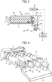
- the toner stored in the toner container 32Y is conveyed in the longitudinal direction (from left to right in FIG. 3 ) by a spiral concave-and-convex portion 33b (projection) that is recessed from the outer circumferential surface side of the container body 33Y and protrudes toward the inner circumferential surface, and the toner is ejected from the toner ejection port W of the cap 34Y.
- the driver 91 drives to rotate the container body 33Y of the toner container 32Y as required, thereby supplying the toner to the toner tank 61Y.
- the toner containers 32Y, 32M, 32C, and 32K are replaced with new ones when the respective service lives thereof have expired, that is, when almost all toner stored in the respective toner containers 32 has been depleted.
- the toner supply device 60Y include the toner container housing 70, the toner tank 61Y, a toner conveying screw 62Y, a stirring member 65Y, a toner end sensor 66Y, and the driver 91.
- the toner tank 61Y is disposed below the toner ejection port W of the toner container 32Y to store the toner ejected through the toner ejection port W of the toner container 32Y.
- a bottom portion of the toner tank 61Y is coupled to an upstream portion of the toner conveying screw 62Y in the direction in which the toner is conveyed.
- the toner end sensor 66Y is disposed on a wall face of the toner tank 61Y at a specified height from the bottom portion and detects that the amount of toner stored in the toner tank 61Y has fallen to a specified amount or less.
- a piezoelectric sensor can be used as the toner end sensor 66Y.
- the controller 90 controls to display that the toner container 32Y is empty (toner depletion) on a display panel of the body of the image forming apparatus 100 to prompt a user to replace the toner container 32Y.
- the stirring member 65Y is disposed at the center of the toner tank 61Y (near the toner end sensor 66Y) to prevent agglomeration of the toner stored in the toner tank 61Y.
- the stirring member 65Y includes a shaft and a flexible member disposed on the shaft.
- the stirring member 65Y rotates clockwise in FIG. 3 to stir the toner in the toner tank 61Y.
- the tip of the flexible member of the stirring member 65Y slidingly contacts a surface where the toner end sensor 66Y detects in rotation cycles. As a result, the toner does not adhere to the surface detected by the toner end sensor 66Y, thereby preventing the detection accuracy from deteriorating.
- the toner conveying screw 62Y conveys the toner stored in the toner tank 61Y obliquely upward. Specifically, the toner conveying screw 62Y conveys the toner linearly from the bottom portion (i.e., bottom point) of the toner tank 61Y toward the upper side of the developing device 5Y. Then, the toner thus conveyed by the toner conveying screw 62Y falls through the downward toner conveyance passage 64Y (see FIG. 2 ) by its own weight and is supplied to the developing device 5Y (the developer housing 54Y).
- the toner container housing 70 typically includes a cap receiving portion 73 for holding the cap 34Y of the toner container 32Y, the rail 72 as a mount (an installation portion) for holding the container body 33Y of the toner container 32Y, and an insertion port 71 as an insertion port through which the toner container 32Y is attached.
- the toner container housing 70 e.g., the insertion port 71 and the rail 72
- the toner containers 32Y, 32M, 32C, and 32K are attached to and detached from the front upper side of the body of the image forming apparatus 100 with the longitudinal direction (a rotation axis direction) of the toner containers 32Y, 32M, 32C, and 32K kept horizontal.
- an attachment-and-detachment operation of the toner containers 32Y, 32M, 32C, and 32K is performed with the longitudinal direction (the rotation axis direction) of the toner containers 32Y, 32M, 32C, and 32K as an attachment-and-detachment direction.
- the rail 72 (serving as a mount) is formed so that the longitudinal length is almost equal to (or slightly longer than) the longitudinal length of the container body 33Y.
- the cap receiving portion 73 is disposed on one end (downstream end in the attachment direction) of the rail 72 in the longitudinal direction, and the insertion port 71 is disposed on the other end (upstream end in the attachment direction) of the rail 72 in the longitudinal direction. Accordingly, in the attachment operation of the toner container 32Y into the toner container housing 70, the cap 34Y passes through the insertion port 71, slides on the rail 72 over a certain distance, and is then attached to the cap receiving portion 73.
- the toner containers 32Y, 32M, 32C, and 32K as powder containers are described in detail.
- the toner container 32Y typically includes a substantially cylindrical container body 33Y (bottle body) and the cap 34Y (bottle cap) into which a head portion (which is a container head portion 33Y2, see FIG. 6 ) of the container body 33Y is inserted.
- the substantially cylindrical container body 33Y rotates around a rotation axis R (see FIG. 3 ) with the rotation axis direction being a direction in which the toner container 32Y is attached and detached (a left-and-right direction in FIG. 3 ), to convey toner (powder) stored therein toward an opening portion A.
- the head portion of the container body 33Y (the container head portion 33Y2) in which the opening portion A is formed is inserted, and the toner ejection port W for ejecting the toner ejected from the opening portion A to the outside of the container body 33Y is disposed in a bottom portion of the cap 34Y.
- the gear 33c that rotates integrally with the container body 33Y, and the opening portion A are disposed on one end in the rotation axis direction (left-and-right direction of FIGS. 2 and 6 ).
- the opening portion A is formed on the container head portion 33Y2 of the container body 33Y (i.e., a leading position when the toner container 32Y is inserted into the toner container housing 70).
- the toner stored in the container body 33Y is ejected through the opening portion A to a space (a cavity) inside the cap 34Y.
- the conveyance of toner from the inside of the container body 33Y to the cavity in the cap 34Y i.e., rotational drive by the container body 33Y
- the gear 33c of the container body 33Y (the container head portion 33Y2) meshes with the drive gear 81 disposed in the toner container housing 70 of the body of the image forming apparatus 100 to rotate the container body 33Y in the direction indicated by the arrow in FIG. 2 with the longitudinal direction as the rotation axis direction.
- the gear 33c is formed to go around the opening portion A, and a plurality of teeth are formed radially with respect to the rotation center of the container body 33Y.
- a part of the gear 33c is exposed from a notch (see FIG. 6 ) formed in the cap 34Y, and the gear 33c meshes with the drive gear 81 of the body of the image forming apparatus 100 at a meshing position located obliquely below the gear 33c.
- a driving force is transmitted from the drive gear 81 to the gear 33c, and the container body 33Y rotates in a specified direction.
- a grip 33d gripped when a user attaches and detaches the toner container 32Y is disposed on a container bottom portion 33Y3 on the other end of the container body 33Y in the longitudinal direction (i.e., on the rear end in the attachment direction).
- a container main portion 33Y1 of the container body 33Y which is a portion different from the container head portion 33Y2 and the container bottom portion 33Y3, has the spiral concave-and-convex portion 33b that is recessed from the outer circumferential surface and protrudes toward the inner circumferential surface.
- the spiral concave-and-convex portion 33b is a portion forming a spiral groove when viewed from the outer circumferential surface and forming a spiral projection when viewed from the inner circumferential surface (see FIGS. 5 and 6 ).
- the spiral concave-and-convex portion 33b ejects toner stored in the container body 33Y through the opening portion A.
- the container main portion 33Y1 of the container body 33Y is formed of press-workable forming paper, which is described later in detail with reference to FIGS. 6 , 7 , 8 , and 9A to 9D .
- the cap 34Y of the toner container 32Y has, for example, the shutter 34d on the bottom portion thereof.
- the opening portion A of the container body 33Y is inserted into the cap 34Y.
- the toner ejection port W ejection port
- the shutter 34d for opening and closing the toner ejection port W is held in a slidable manner in the bottom portion of the cap 34Y.
- the shutter 34d opens the toner ejection port W by a relative movement in the longitudinal direction (i.e., a movement in the direction opposite to the direction indicated by the arrow in FIG. 5 ) from the cap 34Y toward the container body 33Y.
- the shutter 34d closes the toner ejection port W by a relative movement in the longitudinal direction (i.e., a movement in the direction indicated by the arrow in FIG. 5 ) from the container body 33Y toward the cap 34Y.
- the opening-and-closing operation of the shutter 34d (opening-and-closing operation of the toner ejection port W) is performed in conjunction with the attachment-and-detachment operation of the toner container 32Y to and from the toner container housing 70 (the rail 72) in the longitudinal direction (the rotation axis direction).
- the cap 34Y having such a configuration communicates with the container body 33Y via the opening portion A, and the toner ejected from the opening portion A is ejected through the toner ejection port W (i.e., moves in the direction indicated by broken arrow illustrated in FIG. 3 ).
- a substantially cylindrical cavity (space) is formed inside the cap 34Y to extend in the longitudinal direction.
- a cylindrical toner dropping path having a fixed channel area (cross-sectional channel area) extends from a lower circumferential face of the substantially columnar cavity to the toner ejection port W in the cap 34Y.
- the toner container 32Y in the present embodiment that can contain toner as powder inside includes the container body 33Y and the cap 34Y.
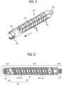
- the container body 33Y typically includes the substantially cylindrical container main portion 33Y1, the container head portion 33Y2 disposed on one end (left in FIG. 6 ) of the container main portion 33Y1 in the rotation axis direction, and the container bottom portion 33Y3 disposed on the other end (right in FIG. 6 ) of the container main portion 33Y1 in the rotation axis direction.
- the container main portion 33Y1 has a substantially cylindrical shape and is rotated around the rotation axis R (see FIG. 3 ) to convey toner (powder) stored therein with the rotation axis direction as the conveyance direction of the toner.
- the container main portion 33Y1 has a plurality of concave-and-convex portions 33b that are recessed from the outer circumferential surface having the substantially cylindrical shape and protrude toward the inner circumferential surface.
- a plurality of concave-and-convex portions 33b are formed in a spiral shape at intervals N (see FIG. 7 ) in a spiral direction.
- the container main portion 33Y1 is rotated to convey the toner stored inside in the rotation axis direction.
- the container main portion 33Y1 is open at both ends in the rotation axis direction.
- the container head portion 33Y2 is disposed to communicate with an opening of the container main portion 33Y1 on the downstream side (left side in FIG. 6 ) in the conveyance direction.
- the container head portion 33Y2 has an opening portion A (see FIG. 3 ) as an ejection port for ejecting toner (powder) conveyed from the container main portion 33Y1 to the outside of the container main portion 33Y1 through the cap 34Y and has the gear 33c on the outer circumferential surface.
- the container head portion 33Y2 is bonded to the container main portion 33Y1 by an adhesive and is rotatable together with the container main portion 33Y1.
- the container bottom portion 33Y3 is disposed to close an opening of the container main portion 33Y1 on the upstream side (right side in FIG. 6 ) in the conveyance direction.
- the container bottom portion 33Y3 is bonded to the container main portion 33Y1 by an adhesive and is rotatable together with the container main portion 33Y1.
- the above-described dimension E mm is a dimension of the container main portion 33Y1 in the rotation axis direction
- the dimension D is a dimension substantially equal to the circumference of the container main portion 33Y1
- the dimension t is a thickness of the container main portion 33Y1.
- the thickness (paper thickness) of forming paper (paper) is preferably in the range of 0.5 to 2 mm.
- the container main portion 33Y1 has a plurality of concave-and-convex portions 33b (33b1 and 33b2) formed by press working.
- Each of the concave-and-convex portions 33b is recessed from the outer circumferential surface (corresponding to a front surface 33Ya illustrated in FIG. 8 ) having a substantially cylindrical shape and protrudes by Y mm to the inner circumferential surface (corresponding to a back surface 33Yb side illustrated in FIG. 8 ).
- the plurality of concave-and-convex portions 33b (33b1 and 33b2) are spirally arranged (spirally formed at intervals N in the spiral direction) on the substantially cylindrical container main portion 33Y1.
- the container body 33Y (the container main portion 33Y1) is rotated so that the toner stored therein is conveyed in the rotation axis direction by the concave-and-convex portion 33b.
- FIG. 7 for the sake of simplicity, only the concave-and-convex portions 33b1 and 33b2 formed at both ends of the flat sheet of forming paper (container main portion 33Y1) are illustrated, and the concave-and-convex portions 33b1 and 33b2 formed at the center of the flat sheet of forming paper are not illustrated.
- the plurality of concave-and-convex portions 33b1 and 33b2 are arranged at substantially same intervals in the rotation axis direction (the left-and-right direction in FIG. 7).
- FIG. 7 is a view of the container main portion 33Y1 having a flat sheet shape before being formed into a cylindrical shape.
- the concave-and-convex portions 33b1 and 33b2 are illustrated in order to facilitate understanding of the positions of the concave-and-convex portions 33b1 and 33b2 after press working.
- Each of the plurality of concave-and-convex portions 33b (33b1 and 33b2) in the present embodiment is a spiral of a half or less of the circumference of the container main portion 33Y1. In other words, the plurality of concave-and-convex portions 33b (33b 1 and 33b2) do not form one continuous spiral.
- Each of the concave-and-convex portions 33b (33b1 and 33b2) is disconnected and forms a spiral independently.
- the plurality of concave-and-convex portions 33b (33b1 and 33b2) formed in this way are also defined as being formed in a spiral shape.
- the container main portion 33Y1 (toner container 32Y) is manufactured through the following steps.
- a "pressing step” is performed in which press working is performed on a flat sheet of forming paper (paper) to form a plurality of concave-and-convex portions 33b that are recessed from the front surface 33Ya and protrude toward the back surface 33Yb.
- the flat sheet of forming paper (paper) is set in a die and press working is performed to form the plurality of concave-and-convex portions 33b (33b 1 and 33b2) on the forming paper.
- a "joining step” is performed of joining ends B1 and B2 of the forming paper (paper) on which the concave-and-convex portions 33b (33b1 and 33b2) are formed to form the substantially cylindrical container main portion 33Y1.
- the concave-and-convex portions 33b 1 and 33b2 are not coupled to each other in a direction (in a circumferential direction) orthogonal to the rotation axis direction, but are divided with a space between the concave-and-convex portion 33b 1 on the lower portion in FIG. 7 and the concave-and-convex portion 33b2 on the upper portion in FIG.
- the container head portion 33Y2 is joined to the head portion of the container main portion 33Y1 by an adhesive
- the container bottom portion 33Y3 is joined to the bottom portion of the container main portion 33Y1 by an adhesive.
- the manufacturing of the container body 33Y is completed (see FIG. 6 ).
- toner is filled into the container body 33Y illustrated in FIG. 6
- the cap 34Y is attached to the container head portion 33Y2 of the container body 33Y.
- the manufacturing of the toner container 32Y is completed (see FIG. 5 ).
- the container head portion 33Y2 is made of a plastic material such as PET (polyethyleneterephthalate) and is formed by plastic molding.
- the container head portion 32Y2 is formed by resin-molding.
- the container head portion 33Y2 is preferably united with, for example, the gear 33c that requires a relatively large mechanical strength, and such a condition is unlikely to be achieved with forming paper.
- the container bottom portion 33Y3 is united with the grip 33d.
- the container bottom portion 33Y3 does not require as much mechanical strength as the container head portion 33Y2. Accordingly, the container bottom portion 33Y3 may be formed by resin-molding or by press working of forming paper.
- the container bottom portion 33Y3 may be formed by resin-molding or by press working of paper.
- the grip 33d when the grip 33d has a simple concave-and-convex shape, the grip 33d is preferably formed with press-workable forming paper in order to reduce the amount of resin.
- the container main portion 33Y1 in the container body 33Y is formed of press-workable forming paper (paper) instead of resin material.
- paper press-workable forming paper
- the toner container 32Y in the present embodiment is formed of press-workable paper, the following effects are also exhibited as compared with a toner container formed by, for example, injection molding, blow molding, or folding: 1) the strength of paper itself is increased, 2) the surface property of paper itself is enhanced, and 3) paper dust is less likely to be generated even with the material as it is or even after the surface is coated (e.g., an abnormal image is less likely to be generated due to the paper dust mixed with toner).
- the toner container 32Y (the container main portion 33Y1) is formed of the forming paper as the press-workable paper.
- the toner container 32Y (the container main portion 33Y1) may be formed of thick paper as the press-workable paper.
- the container main portion 33Y1 is formed such that, after a first semi-cylindrical portion 33Y11 and a second semi-cylindrical portion 33Y12 coupled at a bent portion 33Y10 are formed by press working, the first semi-cylindrical portion 33Y11 and the second semi-cylindrical portion 33Y12 are bent at the bent portion 33Y10 to join the end B 1 of the first semi-cylindrical portion 33Y11 and the end B2 of the second semi-cylindrical portion 33Y12 together into a substantially cylindrical shape.
- the first semi-cylindrical portion 33Y11 and the second semi-cylindrical portion 33Y12 are obtained by equally dividing a cylinder into two portions.
- the press working (pressing step) is performed using an upper die 200A and a lower die 200B so that the concave-and-convex portions 33b1 are formed on the first semi-cylindrical portion 33Y11 and the concave-and-convex portions 33b2 are formed on the second semi-cylindrical portion 33Y12.
- the "pressing step” is a step in which the first semi-cylindrical portion 33Y11 and the second semi-cylindrical portion 33Y12 coupled at the bent portion 33Y10 with respect to a flat sheet of forming paper (paper) are formed, and the plurality of concave-and-convex portions 33b1 and the plurality of concave-and-convex portions 33b2 are formed on the first semi-cylindrical portion 33Y11 and the second semi-cylindrical portion 33Y12, respectively, with reference to FIGS. 9A and 9B .
- FIGS. 9A and 9B With reference to FIGS.
- the "joining step” is a step of joining the end B1 of the first semi-cylindrical portion 33Y11 and the end B2 of the second semi-cylindrical portion 33Y12 together by bending the flat sheet of forming paper at the bent portion 33Y10.
- the above-described "pressing step” can be divided into a “semi-cylindrical portion forming step” in which the first semi-cylindrical portion 33Y11 and the second semi-cylindrical portion 33Y12 coupled to each other at the bent portion 33Y10 with respect to a flat sheet of forming paper (paper) are formed, and a “concave-and-convex portion forming step” in which the concave-and-convex portions 33b1 and 33b2 are formed before and after the "semi-cylindrical portion forming step.”
- the "semi-cylindrical portion forming step” and the “concave-and-convex portion forming step” can be performed simultaneously or at different timings.
- FIG. 9A a flat sheet of forming paper is set between the upper die 200A and the lower die 200B separated from each other.
- the upper die 200A and the lower die 200B have concave portions 210 and 211 and convex portions 230 and 231 for forming the first semi-cylindrical portion 33Y11and the second semi-cylindrical portion 33Y12, respectively, and have peak portions 220 and 221 and valley portions for forming the plurality of concave-and-convex portions 33b1 and 33b2.
- FIG. 9A a flat sheet of forming paper is set between the upper die 200A and the lower die 200B separated from each other.
- the upper die 200A and the lower die 200B have concave portions 210 and 211 and convex portions 230 and 231 for forming the first semi-cylindrical portion 33Y11and the second semi-cylindrical portion 33Y12, respectively, and have peak portions 220 and 221 and valley portions for forming the plurality of concave
- the upper die 200A and the lower die 200B are fitted in a state where a flat sheet of forming paper is set, so that press working is performed on the forming paper. Accordingly, the plurality of concave-and-convex portions 33b 1 and the plurality of concave-and-convex portions 33b2 are formed on the first semi-cylindrical portion 33Y11 and the second semi-cylindrical portion 33Y12, respectively.
- the first semi-cylindrical portion 33Y11 and the second semi-cylindrical portion 33Y12 coupled at the bent portion 33Y10 are taken out from the upper die 200A and the lower die 200B.
- the container main portion 33Y1 (forming paper) after press working illustrated in FIG. 9C is bent at the bent portion 33Y10 as illustrated in FIG. 9D , and the end B1 of the first semi-cylindrical portion 33Y11 and the end B2 of the second semi-cylindrical portion 33Y12 are joined with an adhesive.
- the manufacturing of the substantially cylindrical container main portion 33Y1 is completed.
- the first semi-cylindrical portion 33Y11 and the second semi-cylindrical portion 33Y12 are formed by press working in this way, so that the workability of the step of forming the substantially cylindrical container main portion 33Y1 (joining step) is enhanced as compared with the case of forming a cylinder by rolling a flat sheet of forming paper.
- the plurality of concave-and-convex portions 33b1 and 33b2 are also formed simultaneously in the process of forming the first semi-cylindrical portion 33Y11 and the second semi-cylindrical portion 33Y12 by press working, and thus the number of overall processes does not increase and the production efficiency can be increased.
- the container main portion 33Y1 in the present embodiment is formed such that, in a state of a flat sheet of forming paper before press working (a state developed into a flat shape), both the plurality of concave-and-convex portions 33b 1 formed on the first semi-cylindrical portion 33Y11 and the plurality of concave-and-convex portions 33b2 formed on the second semi-cylindrical portion 33Y12 extend in a direction inclined at a specified angle ⁇ (within ⁇ 85°) with respect to the bent portion 33Y10 extending in the rotation axis direction (the left-and-right direction in FIG. 7 ).
- a virtual line connecting the plurality of concave-and-convex portions 33b1 formed on the first semi-cylindrical portion 33Y11 and the plurality of concave-and-convex portions 33b2 formed on the second semi-cylindrical portion 33Y12 is formed to draw one spiral (one spiral connected alternately up and down from one end in the order of the concave-and-convex portion 33b1 on the rightmost lower side, the concave-and-convex portion 33b2 on the rightmost upper side, the concave-and-convex portion 33b 1 on the second lower right side, and the concave-and-convex portion 33b2 on the second upper right side).
- the plurality of concave-and-convex portions 33b1 and 33b2 are formed to have the same lengths M in a spiral direction (the direction of the inclined angle ⁇ ), the same intervals (pitches) H in the direction orthogonal to the spiral direction, and the same intervals N in the spiral direction at the position straddling the bent portion 33Y10 (and the position straddling the ends B1 and B2).
- the plurality of concave-and-convex portions 33b 1 and 33b2 are not formed at the position of the bent portion 33Y10, so that the bending operation at the bent portion 33Y10 in the joining step described above can be easily performed.
- a concave-and-convex portion is not formed at the positions of the ends B1 and B2, so that the joining operation of the ends B 1 and B2 in the joining step described above can be easily performed.
- a container main portion 33Y1 of the toner container 32Y (container body 33Y) in the first modification is formed such that the concave-and-convex portion 33b2 of the second semi-cylindrical portion 33Y12 is shifted in phase in the rotation axis direction (left-and-right direction in FIG. 10 ) with respect to the concave-and-convex portion 33b1 of the first semi-cylindrical portion 33Y11.
- the substantially cylindrical container main portion 33Y1 (container main portion 33Y1 after completion of manufacturing) is disposed such that a virtual line connecting a plurality of concave-and-convex portions 33b1 formed on the first semi-cylindrical portion 33Y11 draws one spiral (a first spiral), and is formed such that a virtual line connecting a plurality of concave-and-convex portions 33b2 formed on the second semi-cylindrical portion 33Y12 draws one spiral (a second spiral) shifted in the rotation axis direction with respect to the above-described one spiral (the first spiral).
- a double spiral is formed on the container main portion 33Y1 (container body 33Y).
- the container main portion 33Y1 (container body 33Y) is rotated so that toner in the toner container 32Y is conveyed in the rotation axis direction by the plurality of concave-and-convex portions 33b 1 and 33b2. As illustrated in FIG.
- the container main portion 33Y1 is disposed such that one area, closer to the bent portion 33Y10, of one concave-and-convex portion 33b1 formed on the first semi-cylindrical portion 33Y11 and one area, closer to the bent portion 33Y10, of one concave-and-convex portion 33b2 formed on the second semi-cylindrical portion 33Y12 overlap each other by a distance R1 when viewed in the direction orthogonal to the rotation axis direction.
- Such a configuration can enhance toner conveyance property between the concave-and-convex portion 33b1 on the first semi-cylindrical portion 33Y11 and the concave-and-convex portion 33b2 on the second semi-cylindrical portion 33Y12 at the position corresponding to the bent portion 33Y10 when the container main portion 33Y1 (container body 33Y) rotates.
- the overall toner conveyance property is enhanced. As illustrated in FIG.
- the container main portion 33Y1 is disposed such that one area (closer to the end B 1), farther from the bent portion 33Y10, of one concave-and-convex portion 33b1 formed on the first semi-cylindrical portion 33Y11 and one area (close to the end B2), farther from to the bent portion 33Y10, of one concave-and-convex portion 33b2 formed on the second semi-cylindrical portion 33Y12 overlap each other by a distance R2 when viewed in the direction orthogonal to the rotation axis direction.
- Such a configuration can enhance toner conveyance property between the concave-and-convex portion 33b 1 on the first semi-cylindrical portion 33Y11 and the concave-and-convex portion 33b2 on the second semi-cylindrical portion 33Y12 at the position corresponding to the ends B1 and B2 when the container main portion 33Y1 (container body 33Y) rotates.
- the overall toner conveyance property is enhanced.
- a plurality of cuts Z parallel to the rotation axis direction are formed in the container main portion 33Y1 of the toner container 32Y (container body 33Y) in the second modification.
- the cuts Z are formed by cutting the container main portion 33Y1 from the outer circumferential surface (front surface 33Ya) so that the cuts Z do not reach the inner circumferential surface (back surface 33Yb).
- the first semi-cylindrical portion 33Y11 and the second semi-cylindrical portion 33Y12 are not formed in the pressing step (in the press-working step) as illustrated in FIGS. 9A to 9D .
- a plurality of concave-and-convex portions 33b are formed on the flat sheet of forming paper (container main portion 33Y1) illustrated in FIG. 12A .
- the ends B 1 and B2 of the flat sheet of forming paper after press working are joined with each other to form the cylindrical container main portion 33Y1.
- the plurality of cuts Z parallel to the rotation axis direction are formed in the container main portion 33Y1, and thus, the operation of rolling the flat sheet of forming paper into a cylindrical shape in the joining step is easily performed.
- the upper concave-and-convex portion 33b1 and the lower concave-and-convex portion 33b2 can be formed to be shifted in the rotation axis direction as illustrated in FIG. 10 in the pressing of the flat sheet of the forming paper.
- the toner container 32Y in the present embodiment is a powder container that can store powder therein, and includes the substantially cylindrical container main portion 33Y1 that rotates around the rotation axis R to convey toner (powder) stored therein in the conveyance direction along the rotation axis direction.
- the container main portion 33Y1 is formed by press working of forming paper (paper). Such a configuration can reduce the amount of resin used for the toner container 32Y.
- toner containers may contain two-component developer as powder including toner and carrier to be used in an image forming apparatus in which the two-component developer is appropriately supplied to developing devices.
- the toner container 32Y in which toner is stored can be used, and a developer container in which developer is stored can be used.
- the present disclosure is applied to the toner container 32Y that includes the container body 33Y and the cap 34Y, but the toner container (powder container) to which the present disclosure is applied is not limited to this.
- the present disclosure can be applied to, for example, a powder container that includes only a container body (e.g., a toner container that directly ejects toner from an ejection port of a container head portion toward the outside of the container), or a toner container that includes a cap having a toner ejection port at a lateral end surface instead of a bottom portion.
- the present disclosure is applied to the toner container 32Y as the powder container installed in the image forming apparatus 100, but the powder container to which the present disclosure is applied is not limited to this.
- the present disclosure can be also applied to a powder container in which edible powder such as flour or potato starch is stored therein. Even in such a case, effects equivalent to those of the above-described embodiments can be obtained.
- aspects of the present disclosure may be, for example, a combination of the following first to twenty-second aspects.
- a powder container for storing powder inside includes a container main portion (e.g., the container main portion 33Y1).
- the container main portion has a substantially cylindrical shape to rotate around a rotation axis of the container main portion to convey powder stored inside the container main portion in a conveyance direction along a direction of the rotation axis.
- the container main portion is made of paper formed by press working.
- the powder container (e.g., the toner container 32Y) according to the first aspect further includes a container head portion (e.g., the container head portion 33Y2).
- the container head portion is disposed to communicate with an opening of the container main portion (e.g., the container main portion 33Y1) on a downstream side of the container main portion in the conveyance direction.
- the container head portion includes an ejection port to eject the powder conveyed from the container main portion to an outside of the powder container and a gear (e.g., the gear 33c) formed on an outer circumferential surface of the container head portion.
- the container head portion is rotatable together with the container main portion and is made by resin molding.
- the powder container (e.g., the toner container 32Y) according to the first or second aspect includes a container bottom portion (e.g., the container bottom portion 33Y3).
- the container bottom portion is to close an opening of the container main portion (e.g., the container main portion 33Y1) on an upstream side of the container main portion in the conveyance direction.
- the container bottom portion is rotatable together with the container main portion and is made by resin molding or by press working of paper.
- the container main portion (e.g., the container main portion 33Y1) has a plurality of concave-and-convex portions (e.g., the concave-and-convex portions 33b) formed by press working.
- the plurality of concave-and-convex portions are recessed from an outer circumferential surface of the substantially cylindrical shape and protrude toward an inner circumferential surface.
- the plurality of concave-and-convex portions are spirally arranged in the container main portion (e.g., the container main portion 33Y1) having the substantially cylindrical shape.
- each of the plurality of concave-and-convex portions is a spiral of a half of the circumference or less in the container main portion (e.g., the container main portion 33Y1).
- the container main portion (e.g., the container main portion 33Y1) is formed such that a first semi-cylindrical portion (e.g., the first semi-cylindrical portion 33Y11) and a second semi-cylindrical portion (e.g., the second semi-cylindrical portion 33Y12) coupled at a bent portion (e.g., the bent portion 33Y10) are formed by press working and bent at the bent portion to join an end (e.g., the end B 1) of the first semi-cylindrical portion and an end (e.g., the end B2) of the second semi-cylindrical portion together into the substantially cylindrical shape.
- a first semi-cylindrical portion e.g., the first semi-cylindrical portion 33Y11
- a second semi-cylindrical portion e.g., the second semi-cylindrical portion 33Y12
- a bent portion e.g., the bent portion 33Y10
- the plurality of concave-and-convex portions are formed on each of the first semi-cylindrical portion (e.g., the first semi-cylindrical portion 33Y11) and the second semi-cylindrical portion (e.g., the second semi-cylindrical portion 33Y12).
- the container main portion (e.g., the container main portion 33Y1) is formed such that both the plurality of concave-and-convex portions (e.g., the concave-and-convex portions 33b) formed on the first semi-cylindrical portion (e.g., the first semi-cylindrical portion 33Y11) and the plurality of concave-and-convex portions (e.g., the concave-and-convex portions 33b) formed on the second semi-cylindrical portion (e.g., the second semi-cylindrical portion 33Y12) extend in a direction inclined at a specified angle with respect to the bent portion (e.g., the bent portion 33Y10) extending in the direction of the rotation axis.
- the container main portion e.g., the container main portion 33Y1
- both the plurality of concave-and-convex portions e.g., the concave-and-convex portions 33b
- the container main portion e.g., the container main portion 33Y1 having the substantially cylindrical shape is formed such that an imaginary line connecting the plurality of concave-and-convex portions (e.g., the concave-and-convex portions 33b) formed on the first semi-cylindrical portion (e.g., the first semi-cylindrical portion 33Y11) and the plurality of concave-and-convex portions formed on the second semi-cylindrical portion (e.g., the second semi-cylindrical portion 33Y12) draws one spiral.
- the plurality of concave-and-convex portions e.g., the concave-and-convex portions 33b
- the container main portion e.g., the container main portion 33Y1 having the substantially cylindrical shape is formed such that an imaginary line connecting the plurality of concave-and-convex portions (e.g., the concave-and-convex portions 33b) formed on the first semi-cylindrical portion (e.g., the first semi-cylindrical portion 33Y11) draws one spiral, and an imaginary line connecting the plurality of concave-and-convex portions formed on the second semi-cylindrical portion (e.g., the second semi-cylindrical portion 33Y12) draws another spiral shifted in the direction of the rotation axis with respect to the one spiral.
- an imaginary line connecting the plurality of concave-and-convex portions e.g., the concave-and-convex portions 33b
- the first semi-cylindrical portion e.g., the first semi-cylindrical portion 33Y11
- the container main portion (e.g., the container main portion 33Y1) is formed such that one area, closer to the bent portion (e.g., the bent portion 33Y10), of one of the plurality of concave-and-convex portions (e.g., the concave-and-convex portion 33b 1) formed on the first semi-cylindrical portion (e.g., the first semi-cylindrical portion 33Y11) and one area, closer to the bent portion, of one of the plurality of concave-and-convex portions formed on the second semi-cylindrical portion (e.g., the second semi-cylindrical portion 33Y12) overlap each other when viewed in the direction orthogonal to the direction of the rotation axis.
- the container main portion (e.g., the container main portion 33Y1) is formed such that one area, farther from the bent portion (e.g., the bent portion 33Y10), of one of the plurality of concave-and-convex portions (e.g., the concave-and-convex portion 33b 1) formed on the first semi-cylindrical portion (e.g., the first semi-cylindrical portion 33Y11) and one area, farther from the bent portion, of one of the plurality of concave-and-convex portions formed on the second semi-cylindrical portion (e.g., the second semi-cylindrical portion 33Y12) overlap each other when viewed in the direction orthogonal to the rotation axis direction.
- the container main portion (e.g., the container main portion 33Y1) is formed such that one area, farther from the bent portion (e.g., the bent portion 33Y10), of one of the plurality of concave-and-convex portions (e.g., the concave-and-convex portion 33b 1) formed on the first semi-cylindrical portion (e.g., the first semi-cylindrical portion 33Y11) and one area, farther from the bent portion, of one of the plurality of concave-and-convex portions formed on the second semi-cylindrical portion (e.g., the second semi-cylindrical portion 33Y12) overlap each other when viewed in the direction orthogonal to the direction of the rotation axis.
- the container main portion e.g., the container main portion 33Y1
- has a plurality of cuts e.g., the cut Z parallel to the direction of the rotation axis.
- the paper is forming paper.
- the powder container e.g., the toner container 32Y
- the powder container is a toner container or a developer container.
- An image forming apparatus (e.g., the image forming apparatus 100) includes a body and the powder container (e.g., the toner container 32Y) according to any one of the first to eighteenth aspects detachably attached to the body.
- the powder container e.g., the toner container 32Y
- a method of manufacturing a powder container (e.g., the toner container 32Y) for storing powder inside includes performing press working on a flat sheet of paper to form a plurality of concave-and-convex portions (e.g., the concave-and-convex portions 33b) that are recessed from a front surface of the flat sheet of paper and protrude toward a back surface of the flat sheet of paper and joining ends (e.g., the end B 1, B2) of the flat sheet of paper to form a container main portion (e.g., the container main portion 33Y1) having a substantially cylindrical shape after the pressing working.
- a powder container e.g., the toner container 32Y
- a method of manufacturing a powder container for storing powder inside includes performing press working on a flat sheet of paper to form a plurality of concave-and-convex portions (e.g., the concave-and-convex portions 33b) that are recessed from a front surface of the flat sheet of paper and pro
- the method for manufacturing the powder container (e.g., the toner container 32Y) according to the twentieth aspect, the performing the press working includes forming a first semi-cylindrical portion (e.g., the first semi-cylindrical portion 33Y11) and a second semi-cylindrical portion (e.g., the second semi-cylindrical portion 33Y12) connected to each other at a bent portion on the flat sheet of paper and forming a plurality of concave-and-convex portions (e.g., the concave-and-convex portions 33b) on the first semi-cylindrical portion and the second semi-cylindrical portion.
- a first semi-cylindrical portion e.g., the first semi-cylindrical portion 33Y11
- a second semi-cylindrical portion e.g., the second semi-cylindrical portion 33Y12
- the joining includes bending the first semi-cylindrical portion and the second semi-cylindrical portion at the bent portion (e.g., the bent portion 33Y10) to join an end (e.g., the end B 1) of the first semi-cylindrical portion and an end (e.g., the end B2) of the second semi-cylindrical portion to each other.
- the performing the press working includes forming the first semi-cylindrical portion (e.g., the first semi-cylindrical portion 33Y11) and the second semi-cylindrical portion (e.g., the second semi-cylindrical portion 33Y12) connected to each other at the bent portion (e.g., the bent portion 33Y10) on the flat sheet of paper and forming the plurality of concave-and-convex portions (e.g., the concave-and-convex portions 33b) before and after the forming of the first semi-cylindrical-portion forming and the second semi-cylindrical-portion forming are performed.
- the first semi-cylindrical portion e.g., the first semi-cylindrical portion 33Y11
- the second semi-cylindrical portion e.g., the second semi-cylindrical portion 33Y12
Landscapes
- Physics & Mathematics (AREA)
- General Physics & Mathematics (AREA)
- Life Sciences & Earth Sciences (AREA)
- Sustainable Development (AREA)
- Dry Development In Electrophotography (AREA)
Abstract
A powder container (32Y) for storing powder inside includes a container main portion (33Y1). The container main portion (33Y1) has a substantially cylindrical shape to rotate around a rotation axis of the container main portion (33Y1) to convey powder stored inside the container main portion (33Y1) in a conveyance direction along a direction of the rotation axis. The container main portion (33Y1) is a component made of paper formed by press working.
Description
- Embodiments of the present disclosure relate to a powder container in which powder such as toner is stored therein, an image forming apparatus such as a copier, a printer, a facsimile, or a multifunction peripheral thereof including the powder container, and a method for manufacturing the powder container.
- Image forming apparatuses such as copiers and printers are widely known in which a substantially cylindrical toner container attached to and detached from a body of an image forming apparatus is disposed (see, for example,
Japanese Patent No. 5999479 - Specifically, the toner container typically includes a substantially cylindrical container body and a cap in
Japanese Patent No. 5999479 - On the other hand, a technology in which a toner pack for toner refilling in a toner container is detachably attached to the toner container is generally known (see, for example,
Japanese Unexamined Patent Application Publication No. 2022-090641 - In a powder container, most of the components, such as a container body and a cap, are made from resin materials, so that a large amount of resin is used to manufacture one powder container. As a result, an environmental load may increase. In particular, the powder container (toner container) used in an image forming apparatus is frequently replaced, and then, the above-described disadvantage cannot be ignored.
- The present disclosure is made to solve the above-described disadvantage. An object of the present disclosure is to provide a powder container, an image forming apparatus, and a method for manufacturing the powder container, which use a small amount of resin.
- In an embodiment of the present disclosure, a powder container for storing powder inside includes a container main portion. The container main portion has a substantially cylindrical shape to rotate around a rotation axis of the container main portion to convey powder stored inside the container main portion in a conveyance direction along a direction of the rotation axis. The container main portion is a component made of paper formed by press working.
- In another embodiment of the present disclosure, an image forming apparatus includes a body and the powder container detachably attached to the body.
- In still another embodiment of the present disclosure, a method of manufacturing a powder container for storing powder inside includes performing press working on a flat sheet of paper to form a plurality of concave-and-convex portions that are recessed from a front surface of the flat sheet of paper and protrude toward a back surface of the flat sheet of paper and joining ends of the flat sheet of paper to form a container main portion having a substantially cylindrical shape after the pressing working.
- According to the present disclosure, a powder container, an image forming apparatus, and a method for manufacturing the powder container, which use a small amount of resin, can be provided.
- A more complete appreciation of embodiments of the present disclosure and many of the attendant advantages and features thereof can be readily obtained and understood from the following detailed description with reference to the accompanying drawings, wherein:
-
FIG. 1 is a diagram illustrating an overall configuration of an image forming apparatus according to an embodiment of the present disclosure; -
FIG. 2 is a cross-sectional view of an image forming device included in the image forming apparatus ofFIG. 1 ; -
FIG. 3 is a view of a toner container disposed in a toner supply device; -
FIG. 4 is a perspective view of toner containers disposed on a mount; -
FIG. 5 is a perspective view of a toner container; -
FIG. 6 is a side view of a container main portion (a container body) of a toner container; -
FIG. 7 is a plan view of a flat sheet of forming paper before formation of a substantially cylindrical container main portion; -
FIG. 8 is a cross-sectional view of a concave-and-convex portion, taken along line A-A ofFIG. 7 ; -
FIGS. 9A to 9D are diagrams illustrating a step of manufacturing a substantially cylindrical container main portion; -
FIG. 10 is a plan view of a flat sheet of forming paper before formation of a substantially cylindrical container main portion, according to a first modification; -
FIG. 11 is a plan view of a flat sheet of forming paper on which press working is performed, according to a second modification; and -
FIGS. 12A and 12B are diagrams illustrating a step of manufacturing a substantially cylindrical container main portion after the press working ofFIG. 11 . - The accompanying drawings are intended to depict embodiments of the present disclosure and should not be interpreted to limit the scope thereof. The accompanying drawings are not to be considered as drawn to scale unless explicitly noted. Also, identical or similar reference numerals designate identical or similar components throughout the several views.
- In describing embodiments illustrated in the drawings, specific terminology is employed for the sake of clarity. However, the disclosure of this specification is not intended to be limited to the specific terminology so selected and it is to be understood that each specific element includes all technical equivalents that have a similar function, operate in a similar manner, and achieve a similar result.
- Referring now to the drawings, embodiments of the present disclosure are described below. Like reference signs are assigned to like elements or components and descriptions of those elements or components may be simplified or omitted. As used herein, the singular forms "a," "an," and "the" are intended to include the plural forms as well, unless the context clearly indicates otherwise.
- A configuration and operation of an
image forming apparatus 100 is described below. As illustrated inFIG. 1 , fourtoner containers FIG. 4 ) in an upper area of a body of theimage forming apparatus 100. Thetoner containers image forming apparatus 100 by an operator such as a user. Anintermediate transfer unit 15 is disposed below thetoner container housing 70.Image forming devices intermediate transfer belt 8 of theintermediate transfer unit 15.Toner supply devices toner containers toner containers toner supply devices image forming devices - With reference to
FIG. 2 , theimage forming device 6Y for yellow includes aphotoconductor drum 1Y, acharging device 4Y, a developingdevice 5Y, acleaning device 2Y, and an electric-charge removing device disposed around thephotoconductor drum 1Y. - Image forming processes (i.e., a charging process, an exposure process, a development process, a transfer process, a cleaning process, and an electric-charge removing process) are executed on the
photoconductor drum 1Y. Thus, a yellow toner image is formed on the surface of thephotoconductor drum 1Y. - The other three
image forming devices image forming device 6Y for yellow except for the color of toner used therein and form magenta, cyan, and black toner images, respectively. Only theimage forming unit 6Y is described below and descriptions of the other threeimage forming units - As illustrated in
FIG. 2 , a drive motor drives to rotate thephotoconductor drum 1Y in a clockwise direction. Thecharging device 4Y uniformly charges the surface of thephotoconductor drum 1Y (charging process). When the surface of thephotoconductor drum 1Y reaches a position at which the surface of thephotoconductor drum 1Y is irradiated with a laser beam L emitted from an exposure device 7 (seeFIG. 1 ), thephotoconductor drum 1Y is scanned with the laser beam L at the position. Thus, an electrostatic latent image corresponding to yellow is formed on thephotoconductor drum 1Y (exposure process). - When the surface of the
photoconductor drum 1Y reaches a position facing the developingdevice 5Y, the electrostatic latent image is developed with toner into a yellow toner image (development process). When the surface of thephotoconductor drum 1Y bearing the toner image reaches a position facing aprimary transfer roller 9Y via theintermediate transfer belt 8, at the position, the toner image on thephotoconductor drum 1Y is transferred onto the intermediate transfer belt 8 (primary transfer process). After the primary transfer process, a slight amount of untransferred toner remains on thephotoconductor drum 1Y. - When the surface of the
photoconductor drum 1Y reaches a position opposite thecleaning device 2Y, acleaning blade 2a of thecleaning device 2Y mechanically collects the untransferred toner on thephotoconductor drum 1Y (cleaning process). Finally, the surface of thephotoconductor drum 1Y reaches a position facing the electric-charge removing device, and residual potential on thephotoconductor drum 1Y is removed at this position (electric-charge removing process). Thus, a series of image forming processes executed on the surface of thephotoconductor drum 1Y is completed. - The other
image forming devices image forming device 6Y for yellow. In other words, theexposure device 7 disposed below theimage forming devices image forming devices intermediate transfer belt 8. Thus, a color toner image is formed on theintermediate transfer belt 8. - With reference to
FIG. 1 , theintermediate transfer unit 15 includes theintermediate transfer belt 8, the fourprimary transfer rollers transfer counter roller 12, tension rollers, and an intermediate-transfer-belt cleaner. Theintermediate transfer belt 8 is stretched around and supported by multiple rollers and is rotated in the direction indicated by arrow illustrated inFIG. 1 as one of the multiple rollers that serves as a drive roller rotates (i.e., the secondary-transfer counter roller 12). - The four
primary transfer rollers photoconductor drums intermediate transfer belt 8 to form primary transfer nips. A primary transfer bias opposite in polarity to toner is applied to theprimary transfer rollers intermediate transfer belt 8 travels in the direction (counterclockwise) indicated by an arrow inFIG. 1 and sequentially passes through the primary transfer nips of the fourprimary transfer rollers intermediate transfer belt 8, thereby forming the multicolor toner image (primary transfer process). - Subsequently, the
intermediate transfer belt 8 onto which the toner images of the respective colors are transferred and superimposed reaches a position opposite asecondary transfer roller 19. At this position, theintermediate transfer belt 8 is nipped between the secondary-transfer counter roller 12 and thesecondary transfer roller 19 to form a secondary transfer nip. The toner images of four colors formed on theintermediate transfer belt 8 are transferred onto a sheet P such as a sheet of paper conveyed to the position of the secondary transfer nip (secondary transfer process). At this time, the untransferred toner that has not been transferred onto the sheet P remains on the surface of theintermediate transfer belt 8. The surface of theintermediate transfer belt 8 then reaches a position opposite the intermediate-transfer-belt cleaner. At the position, the intermediate-transfer-belt cleaner collects the untransferred toner from the surface of theintermediate transfer belt 8. Thus, a series of transfer processes performed on theintermediate transfer belt 8 ends. - The sheet P is conveyed from a
sheet feeder 26 disposed in a lower portion of the body of theimage forming apparatus 100 to the secondary transfer nip via afeed roller 27 and aregistration roller pair 28. Specifically, thesheet feeder 26 contains a stack of multiple sheets P such as sheets of paper stacked on one on another. As thefeed roller 27 is rotated counterclockwise inFIG. 1 , thefeed roller 27 feeds a top sheet P from the stack in thesheet feeder 26 to a roller nip between rollers of theregistration roller pair 28. - The sheet P conveyed to the
registration roller pair 28 temporarily stops at a position of the roller nip between the rollers of theregistration roller pair 28 that has stopped rotating. Theregistration roller pair 28 is rotated at a timing at which the sheet P meets the color toner image on theintermediate transfer belt 8 at the secondary transfer nip, to convey the sheet P toward the secondary transfer nip. Thus, the desired color image is transferred onto the sheet P. - Subsequently, the sheet P, onto which the color toner image is transferred at the secondary transfer nip, is conveyed to a position of a fixing
device 20. Then, at this position, the color toner image transferred to the surface of the sheet P is fixed on the sheet P by heat and pressure of a fixing belt and a pressing roller. Subsequently, the sheet P is conveyed through the rollers of anoutput roller pair 29 and ejected to the outside of theimage forming apparatus 100. The sheets P ejected by theoutput roller pair 29 to the outside of theimage forming apparatus 100 are sequentially stacked as output images on astack tray 30. Thus, a series of image forming processes performed by theimage forming apparatus 100 is completed. - A detailed description is provided of a configuration and operation of the developing
device 5Y of theimage forming device 6Y with reference toFIG. 2 . The developingdevice 5Y includes a developingroller 51Y disposed opposite thephotoconductor drum 1Y, adoctor blade 52Y disposed opposite the developingroller 51Y, two conveyingscrews 55Y disposed indeveloper housings toner concentration sensor 56Y to detect concentration of toner in developer G. The developingroller 51Y includes a magnet and a sleeve. The magnet is fixed inside the developingroller 51Y. The sleeve rotates around the magnet. Thedeveloper housings developer housing 54Y communicates, via an opening on an upper side thereof, with a downwardtoner conveyance passage 64Y. - The developing
device 5Y described above operates as follows. The sleeve of the developingroller 51Y rotates in a direction indicated by an arrow inFIG. 2 . The developer G is carried on the developingroller 51Y by a magnetic field generated by the magnet. As the sleeve rotates, the developer G moves along the outer circumferential surface of the developingroller 51Y. - The developer G in the developing
device 5Y is adjusted so that the ratio of toner (toner concentration) in the developer G is within a specified range. More specifically, thetoner supply device 60Y (seeFIG. 3 ) supplies toner (as powder) from thetoner container 32Y to thedeveloper housing 54Y according to the toner consumption in the developingdevice 5Y. The configuration and operation of the toner supply device are described in detail below. - The two conveying
screws 55Y mix and stir the developer G with the toner supplied to thedeveloper housing 54Y while circulating with the developer G in the twodeveloper housings FIG. 2 is illustrated. The toner in the developer G is electrically charged by friction with the carrier, so that the toner is attracted to the carrier. Both the toner and the carrier are borne on the developingroller 51Y due to a magnetic force generated on the developingroller 51Y. - The developer G borne on the developing
roller 51Y is conveyed in the direction indicated by arrow inFIG. 2 and reaches a position opposite thedoctor blade 52Y. At this position, thedoctor blade 52Y adjusts the amount of the developer G on the developingroller 51Y to an appropriate amount. Thereafter, the developer G on the developingroller 51Y is conveyed to a position opposite thephotoconductor drum 1Y (i.e., which is a development area). The toner is attracted to the electrostatic latent image formed on thephotoconductor drum 1Y by an electric field generated in the developing area. As the sleeve rotates, the developer G remaining on the developingroller 51Y reaches an upper part of thedeveloper housing 53Y and separates from the developingroller 51Y. - With reference to
FIGS. 3 and 4 , thetoner supply devices FIG. 3 , the respective color toners in thetoner containers toner container housing 70 in the body of theimage forming apparatus 100 are supplied to the corresponding developing devices by thetoner supply devices toner supply devices toner containers toner supply device 60Y and thetoner container 32Y for yellow are described below as representatives, and descriptions of thetoner supply devices toner containers - As illustrated in
FIG. 4 , when thetoner containers rail 72 as a mount) of the body of theimage forming apparatus 100,shutters 34d of thetoner containers FIG. 3 ) of thetoner supply devices toner containers toner supply devices toner tanks 61Y, 61M, 61C, and 61K of thetoner supply device FIG. 3 , thetoner container 32Y is a substantially cylindrical toner bottle and typically includes acap 34Y and acontainer body 33Y (i.e., a bottle body) formed together with agear 33c (seeFIG. 6 ). Thecap 34Y is held by thetoner container housing 70 not to rotate. Thecontainer body 33Y is held so as to be rotatable relative to thecap 34Y and is rotated by a driver 91 (including a drive motor and a drive gear 81) in the direction indicated by an arrow illustrated inFIG. 3 . As thecontainer body 33Y itself rotates, the toner stored in thetoner container 32Y (container body 33Y) is conveyed in the longitudinal direction (from left to right inFIG. 3 ) by a spiral concave-and-convex portion 33b (projection) that is recessed from the outer circumferential surface side of thecontainer body 33Y and protrudes toward the inner circumferential surface, and the toner is ejected from the toner ejection port W of thecap 34Y. In other words, thedriver 91 drives to rotate thecontainer body 33Y of thetoner container 32Y as required, thereby supplying the toner to thetoner tank 61Y. Thetoner containers - With reference to
FIG. 3 , thetoner supply device 60Y include thetoner container housing 70, thetoner tank 61Y, atoner conveying screw 62Y, a stirringmember 65Y, atoner end sensor 66Y, and thedriver 91. Thetoner tank 61Y is disposed below the toner ejection port W of thetoner container 32Y to store the toner ejected through the toner ejection port W of thetoner container 32Y. A bottom portion of thetoner tank 61Y is coupled to an upstream portion of thetoner conveying screw 62Y in the direction in which the toner is conveyed. Thetoner end sensor 66Y is disposed on a wall face of thetoner tank 61Y at a specified height from the bottom portion and detects that the amount of toner stored in thetoner tank 61Y has fallen to a specified amount or less. For example, a piezoelectric sensor can be used as thetoner end sensor 66Y. When acontroller 90 detects that the amount of toner stored in thetoner tank 61Y is a predetermined amount or less by thetoner end sensor 66Y, thecontroller 90 controls the driver 91 (e.g., the drive gear 81) to rotate thecontainer body 33Y of thetoner container 32Y for a specified time, and to supply toner to thetoner tank 61Y. If thetoner end sensor 66Y continues to detect "toner end" even when this operation is repeated for a specified number of times, thecontroller 90 controls to display that thetoner container 32Y is empty (toner depletion) on a display panel of the body of theimage forming apparatus 100 to prompt a user to replace thetoner container 32Y. - The stirring
member 65Y is disposed at the center of thetoner tank 61Y (near thetoner end sensor 66Y) to prevent agglomeration of the toner stored in thetoner tank 61Y. The stirringmember 65Y includes a shaft and a flexible member disposed on the shaft. The stirringmember 65Y rotates clockwise inFIG. 3 to stir the toner in thetoner tank 61Y. The tip of the flexible member of the stirringmember 65Y slidingly contacts a surface where thetoner end sensor 66Y detects in rotation cycles. As a result, the toner does not adhere to the surface detected by thetoner end sensor 66Y, thereby preventing the detection accuracy from deteriorating. - The
toner conveying screw 62Y conveys the toner stored in thetoner tank 61Y obliquely upward. Specifically, thetoner conveying screw 62Y conveys the toner linearly from the bottom portion (i.e., bottom point) of thetoner tank 61Y toward the upper side of the developingdevice 5Y. Then, the toner thus conveyed by thetoner conveying screw 62Y falls through the downwardtoner conveyance passage 64Y (seeFIG. 2 ) by its own weight and is supplied to the developingdevice 5Y (thedeveloper housing 54Y). - With reference to
FIG. 4 , thetoner container housing 70 typically includes acap receiving portion 73 for holding thecap 34Y of thetoner container 32Y, therail 72 as a mount (an installation portion) for holding thecontainer body 33Y of thetoner container 32Y, and aninsertion port 71 as an insertion port through which thetoner container 32Y is attached. - With reference to
FIG. 1 , when an opening-and-closing door 110 (seeFIG. 4 ) disposed on the front side of the body of the image forming apparatus 100 (i.e., which is on the front side in the direction perpendicular to the surface of the plane on whichFIG. 1 is illustrated) is opened, the toner container housing 70 (e.g., theinsertion port 71 and the rail 72) is exposed. Thetoner containers image forming apparatus 100 with the longitudinal direction (a rotation axis direction) of thetoner containers toner containers toner containers container body 33Y. Thecap receiving portion 73 is disposed on one end (downstream end in the attachment direction) of therail 72 in the longitudinal direction, and theinsertion port 71 is disposed on the other end (upstream end in the attachment direction) of therail 72 in the longitudinal direction. Accordingly, in the attachment operation of thetoner container 32Y into thetoner container housing 70, thecap 34Y passes through theinsertion port 71, slides on therail 72 over a certain distance, and is then attached to thecap receiving portion 73. - With reference to
FIG. 5 , thetoner containers FIG. 5 , thetoner container 32Y typically includes a substantiallycylindrical container body 33Y (bottle body) and thecap 34Y (bottle cap) into which a head portion (which is a container head portion 33Y2, seeFIG. 6 ) of thecontainer body 33Y is inserted. The substantiallycylindrical container body 33Y rotates around a rotation axis R (seeFIG. 3 ) with the rotation axis direction being a direction in which thetoner container 32Y is attached and detached (a left-and-right direction inFIG. 3 ), to convey toner (powder) stored therein toward an opening portion A. In thecap 34Y, the head portion of thecontainer body 33Y (the container head portion 33Y2) in which the opening portion A is formed is inserted, and the toner ejection port W for ejecting the toner ejected from the opening portion A to the outside of thecontainer body 33Y is disposed in a bottom portion of thecap 34Y. - With reference to
FIGS. 2 and6 , in the container head portion 33Y2 of the substantiallycylindrical container body 33Y, thegear 33c that rotates integrally with thecontainer body 33Y, and the opening portion A are disposed on one end in the rotation axis direction (left-and-right direction ofFIGS. 2 and6 ). The opening portion A is formed on the container head portion 33Y2 of thecontainer body 33Y (i.e., a leading position when thetoner container 32Y is inserted into the toner container housing 70). The toner stored in thecontainer body 33Y is ejected through the opening portion A to a space (a cavity) inside thecap 34Y. The conveyance of toner from the inside of thecontainer body 33Y to the cavity in thecap 34Y (i.e., rotational drive by thecontainer body 33Y) is appropriately performed so that the toner in thecap 34Y does not go below a specified waterline. - The
gear 33c of thecontainer body 33Y (the container head portion 33Y2) meshes with thedrive gear 81 disposed in thetoner container housing 70 of the body of theimage forming apparatus 100 to rotate thecontainer body 33Y in the direction indicated by the arrow inFIG. 2 with the longitudinal direction as the rotation axis direction. Specifically, thegear 33c is formed to go around the opening portion A, and a plurality of teeth are formed radially with respect to the rotation center of thecontainer body 33Y. A part of thegear 33c is exposed from a notch (seeFIG. 6 ) formed in thecap 34Y, and thegear 33c meshes with thedrive gear 81 of the body of theimage forming apparatus 100 at a meshing position located obliquely below thegear 33c. A driving force is transmitted from thedrive gear 81 to thegear 33c, and thecontainer body 33Y rotates in a specified direction. - With reference to
FIGS. 4 to 6 , agrip 33d gripped when a user attaches and detaches thetoner container 32Y is disposed on a container bottom portion 33Y3 on the other end of thecontainer body 33Y in the longitudinal direction (i.e., on the rear end in the attachment direction). The user grips thegrip 33d to attach thetoner container 32Y to the body of the image forming apparatus 100 (the rail 72), which is a movement of thetoner container 32Y in the direction indicated by the arrow illustrated inFIG. 5 . - A container main portion 33Y1 of the
container body 33Y, which is a portion different from the container head portion 33Y2 and the container bottom portion 33Y3, has the spiral concave-and-convex portion 33b that is recessed from the outer circumferential surface and protrudes toward the inner circumferential surface. The spiral concave-and-convex portion 33b is a portion forming a spiral groove when viewed from the outer circumferential surface and forming a spiral projection when viewed from the inner circumferential surface (seeFIGS. 5 and 6 ). The spiral concave-and-convex portion 33b ejects toner stored in thecontainer body 33Y through the opening portion A. When thecontainer body 33Y rotates around the rotation axis R with the longitudinal direction as the rotation axis direction, the spiral concave-and-convex portion 33b conveys the toner toward the opening portion A and ejects the toner from the opening portion A. In the present embodiment, the container main portion 33Y1 of thecontainer body 33Y is formed of press-workable forming paper, which is described later in detail with reference toFIGS. 6 ,7 ,8 , and9A to 9D . - With reference to
FIGS. 3 ,5, and 6 , thecap 34Y of thetoner container 32Y has, for example, theshutter 34d on the bottom portion thereof. The opening portion A of thecontainer body 33Y is inserted into thecap 34Y. In the bottom portion of thecap 34Y, the toner ejection port W (ejection port) is formed for ejecting (falling by its own weight) the toner ejected from the opening portion A of thecontainer body 33Y vertically downward and outside thecontainer body 33Y. Theshutter 34d (seeFIGS. 3 and5 ) for opening and closing the toner ejection port W is held in a slidable manner in the bottom portion of thecap 34Y. Specifically, theshutter 34d opens the toner ejection port W by a relative movement in the longitudinal direction (i.e., a movement in the direction opposite to the direction indicated by the arrow inFIG. 5 ) from thecap 34Y toward thecontainer body 33Y. Theshutter 34d closes the toner ejection port W by a relative movement in the longitudinal direction (i.e., a movement in the direction indicated by the arrow inFIG. 5 ) from thecontainer body 33Y toward thecap 34Y. The opening-and-closing operation of theshutter 34d (opening-and-closing operation of the toner ejection port W) is performed in conjunction with the attachment-and-detachment operation of thetoner container 32Y to and from the toner container housing 70 (the rail 72) in the longitudinal direction (the rotation axis direction). - The
cap 34Y having such a configuration communicates with thecontainer body 33Y via the opening portion A, and the toner ejected from the opening portion A is ejected through the toner ejection port W (i.e., moves in the direction indicated by broken arrow illustrated inFIG. 3 ). In the present embodiment, a substantially cylindrical cavity (space) is formed inside thecap 34Y to extend in the longitudinal direction. In addition, a cylindrical toner dropping path having a fixed channel area (cross-sectional channel area) extends from a lower circumferential face of the substantially columnar cavity to the toner ejection port W in thecap 34Y. With this configuration, the toner ejected from the opening portion A of thecontainer body 33Y to the cavity in thecap 34Y smoothly drops through the toner ejection port W outside the container (thetoner tank 61Y) by its own weight. - A description is given below of a configuration and an operation of the
toner container 32Y (32M, 32C, 32K) according to the present embodiment. As described above with reference toFIGS. 5 and 6 , thetoner container 32Y in the present embodiment that can contain toner as powder inside includes thecontainer body 33Y and thecap 34Y. As illustrated inFIG. 6 , thecontainer body 33Y typically includes the substantially cylindrical container main portion 33Y1, the container head portion 33Y2 disposed on one end (left inFIG. 6 ) of the container main portion 33Y1 in the rotation axis direction, and the container bottom portion 33Y3 disposed on the other end (right inFIG. 6 ) of the container main portion 33Y1 in the rotation axis direction. - The container main portion 33Y1 has a substantially cylindrical shape and is rotated around the rotation axis R (see
FIG. 3 ) to convey toner (powder) stored therein with the rotation axis direction as the conveyance direction of the toner. Specifically, the container main portion 33Y1 has a plurality of concave-and-convex portions 33b that are recessed from the outer circumferential surface having the substantially cylindrical shape and protrude toward the inner circumferential surface. A plurality of concave-and-convex portions 33b are formed in a spiral shape at intervals N (seeFIG. 7 ) in a spiral direction. The container main portion 33Y1 is rotated to convey the toner stored inside in the rotation axis direction. The container main portion 33Y1 is open at both ends in the rotation axis direction. The container head portion 33Y2 is disposed to communicate with an opening of the container main portion 33Y1 on the downstream side (left side inFIG. 6 ) in the conveyance direction. The container head portion 33Y2 has an opening portion A (seeFIG. 3 ) as an ejection port for ejecting toner (powder) conveyed from the container main portion 33Y1 to the outside of the container main portion 33Y1 through thecap 34Y and has thegear 33c on the outer circumferential surface. The container head portion 33Y2 is bonded to the container main portion 33Y1 by an adhesive and is rotatable together with the container main portion 33Y1. The container bottom portion 33Y3 is disposed to close an opening of the container main portion 33Y1 on the upstream side (right side inFIG. 6 ) in the conveyance direction. The container bottom portion 33Y3 is bonded to the container main portion 33Y1 by an adhesive and is rotatable together with the container main portion 33Y1. - With reference to
FIGS. 7, 8 , and9A to 9D , in the present embodiment, the container main portion 33Y1 is formed by press working of forming paper such as a pulp mold. In other words, the container main portion 33Y1 is formed by press working of forming paper as a paper. In detail, the container main portion 33Y1 is not formed of general paper that is likely to be broken or cracked during forming and is formed of forming paper that can be formed by press working. Specifically, the container main portion 33Y1 is manufactured by press working of a flat sheet of forming paper (a rectangular sheet of forming paper having a thickness of t mm and a dimension of E mm × D mm). The above-described dimension E mm is a dimension of the container main portion 33Y1 in the rotation axis direction, the dimension D is a dimension substantially equal to the circumference of the container main portion 33Y1, and the dimension t is a thickness of the container main portion 33Y1. In the present embodiment, the thickness (paper thickness) of forming paper (paper) is preferably in the range of 0.5 to 2 mm. - The container main portion 33Y1 has a plurality of concave-and-
convex portions 33b (33b1 and 33b2) formed by press working. Each of the concave-and-convex portions 33b is recessed from the outer circumferential surface (corresponding to a front surface 33Ya illustrated inFIG. 8 ) having a substantially cylindrical shape and protrudes by Y mm to the inner circumferential surface (corresponding to a back surface 33Yb side illustrated inFIG. 8 ). The plurality of concave-and-convex portions 33b (33b1 and 33b2) are spirally arranged (spirally formed at intervals N in the spiral direction) on the substantially cylindrical container main portion 33Y1. Thecontainer body 33Y (the container main portion 33Y1) is rotated so that the toner stored therein is conveyed in the rotation axis direction by the concave-and-convex portion 33b. InFIG. 7 , for the sake of simplicity, only the concave-and-convex portions 33b1 and 33b2 formed at both ends of the flat sheet of forming paper (container main portion 33Y1) are illustrated, and the concave-and-convex portions 33b1 and 33b2 formed at the center of the flat sheet of forming paper are not illustrated. However, the plurality of concave-and-convex portions 33b1 and 33b2 are arranged at substantially same intervals in the rotation axis direction (the left-and-right direction inFIG. 7). FIG. 7 (andFIG. 10 to be described later) is a view of the container main portion 33Y1 having a flat sheet shape before being formed into a cylindrical shape. However, the concave-and-convex portions 33b1 and 33b2 are illustrated in order to facilitate understanding of the positions of the concave-and-convex portions 33b1 and 33b2 after press working. Each of the plurality of concave-and-convex portions 33b (33b1 and 33b2) in the present embodiment is a spiral of a half or less of the circumference of the container main portion 33Y1. In other words, the plurality of concave-and-convex portions 33b (33b 1 and 33b2) do not form one continuous spiral. Each of the concave-and-convex portions 33b (33b1 and 33b2) is disconnected and forms a spiral independently. In the present specification, the plurality of concave-and-convex portions 33b (33b1 and 33b2) formed in this way are also defined as being formed in a spiral shape. - As described above, in the present embodiment, the container main portion 33Y1 (
toner container 32Y) is manufactured through the following steps. First, as illustrated inFIGS. 7 and 8 , a "pressing step" is performed in which press working is performed on a flat sheet of forming paper (paper) to form a plurality of concave-and-convex portions 33b that are recessed from the front surface 33Ya and protrude toward the back surface 33Yb. In other words, the flat sheet of forming paper (paper) is set in a die and press working is performed to form the plurality of concave-and-convex portions 33b (33b 1 and 33b2) on the forming paper. After the press-working step, a "joining step" is performed of joining ends B1 and B2 of the forming paper (paper) on which the concave-and-convex portions 33b (33b1 and 33b2) are formed to form the substantially cylindrical container main portion 33Y1. In order to easily perform the above-described joining step, as illustrated inFIG. 7 , the concave-and-convex portions 33bconvex portion 33bFIG. 7 and the concave-and-convex portion 33b2 on the upper portion inFIG. 7 . After the joining step, the container head portion 33Y2 is joined to the head portion of the container main portion 33Y1 by an adhesive, and the container bottom portion 33Y3 is joined to the bottom portion of the container main portion 33Y1 by an adhesive. Thus, the manufacturing of thecontainer body 33Y is completed (seeFIG. 6 ). Thereafter, toner is filled into thecontainer body 33Y illustrated inFIG. 6 , and thecap 34Y is attached to the container head portion 33Y2 of thecontainer body 33Y. Thus, the manufacturing of thetoner container 32Y is completed (seeFIG. 5 ). - In the present embodiment, the container head portion 33Y2 is made of a plastic material such as PET (polyethyleneterephthalate) and is formed by plastic molding. In other words, the container head portion 32Y2 is formed by resin-molding. This is because the container head portion 33Y2 is preferably united with, for example, the
gear 33c that requires a relatively large mechanical strength, and such a condition is unlikely to be achieved with forming paper. On the other hand, the container bottom portion 33Y3 is united with thegrip 33d. However, the container bottom portion 33Y3 does not require as much mechanical strength as the container head portion 33Y2. Accordingly, the container bottom portion 33Y3 may be formed by resin-molding or by press working of forming paper. In other words, the container bottom portion 33Y3 may be formed by resin-molding or by press working of paper. In particular, when thegrip 33d has a simple concave-and-convex shape, thegrip 33d is preferably formed with press-workable forming paper in order to reduce the amount of resin. - As described above, in the
toner container 32Y in the present embodiment, at least the container main portion 33Y1 in thecontainer body 33Y is formed of press-workable forming paper (paper) instead of resin material. Thus, the amount of resin used is reduced. Such a configuration can reduce the environmental load and the cost of thetoner container 32Y. Thetoner container 32Y in the present embodiment is formed of press-workable paper, the following effects are also exhibited as compared with a toner container formed by, for example, injection molding, blow molding, or folding: 1) the strength of paper itself is increased, 2) the surface property of paper itself is enhanced, and 3) paper dust is less likely to be generated even with the material as it is or even after the surface is coated (e.g., an abnormal image is less likely to be generated due to the paper dust mixed with toner). In the present embodiment, thetoner container 32Y (the container main portion 33Y1) is formed of the forming paper as the press-workable paper. However, thetoner container 32Y (the container main portion 33Y1) may be formed of thick paper as the press-workable paper. - With reference to
FIGS. 9A to 9D (andFIG. 7 ), in the present embodiment, the container main portion 33Y1 is formed such that, after a first semi-cylindrical portion 33Y11 and a second semi-cylindrical portion 33Y12 coupled at a bent portion 33Y10 are formed by press working, the first semi-cylindrical portion 33Y11 and the second semi-cylindrical portion 33Y12 are bent at the bent portion 33Y10 to join theend B 1 of the first semi-cylindrical portion 33Y11 and the end B2 of the second semi-cylindrical portion 33Y12 together into a substantially cylindrical shape. In the present embodiment, the first semi-cylindrical portion 33Y11 and the second semi-cylindrical portion 33Y12 are obtained by equally dividing a cylinder into two portions. The press working (pressing step) is performed using anupper die 200A and alower die 200B so that the concave-and-convex portions 33b1 are formed on the first semi-cylindrical portion 33Y11 and the concave-and-convex portions 33b2 are formed on the second semi-cylindrical portion 33Y12. - Accordingly, in the method for manufacturing the container main portion 33Y1 described above, the "pressing step" is a step in which the first semi-cylindrical portion 33Y11 and the second semi-cylindrical portion 33Y12 coupled at the bent portion 33Y10 with respect to a flat sheet of forming paper (paper) are formed, and the plurality of concave-and-convex portions 33b1 and the plurality of concave-and-convex portions 33b2 are formed on the first semi-cylindrical portion 33Y11 and the second semi-cylindrical portion 33Y12, respectively, with reference to
FIGS. 9A and 9B . With reference toFIGS. 9C and 9D , the "joining step" is a step of joining the end B1 of the first semi-cylindrical portion 33Y11 and the end B2 of the second semi-cylindrical portion 33Y12 together by bending the flat sheet of forming paper at the bent portion 33Y10. The above-described "pressing step" can be divided into a "semi-cylindrical portion forming step" in which the first semi-cylindrical portion 33Y11 and the second semi-cylindrical portion 33Y12 coupled to each other at the bent portion 33Y10 with respect to a flat sheet of forming paper (paper) are formed, and a "concave-and-convex portion forming step" in which the concave-and-convex portions 33b1 and 33b2 are formed before and after the "semi-cylindrical portion forming step." In other words, the "semi-cylindrical portion forming step" and the "concave-and-convex portion forming step" can be performed simultaneously or at different timings. - A description is given of a process of manufacturing the container main portion 33Y1 in more detail with reference to
FIGS. 9A to 9D . First, as illustrated inFIG. 9A , a flat sheet of forming paper is set between theupper die 200A and thelower die 200B separated from each other. Theupper die 200A and thelower die 200B haveconcave portions convex portions peak portions FIG. 9B , theupper die 200A and thelower die 200B are fitted in a state where a flat sheet of forming paper is set, so that press working is performed on the forming paper. Accordingly, the plurality of concave-and-convex portions 33bFIG. 9C ) are taken out from theupper die 200A and thelower die 200B. The container main portion 33Y1 (forming paper) after press working illustrated inFIG. 9C is bent at the bent portion 33Y10 as illustrated inFIG. 9D , and the end B1 of the first semi-cylindrical portion 33Y11 and the end B2 of the second semi-cylindrical portion 33Y12 are joined with an adhesive. Thus, the manufacturing of the substantially cylindrical container main portion 33Y1 is completed. - The first semi-cylindrical portion 33Y11 and the second semi-cylindrical portion 33Y12 are formed by press working in this way, so that the workability of the step of forming the substantially cylindrical container main portion 33Y1 (joining step) is enhanced as compared with the case of forming a cylinder by rolling a flat sheet of forming paper. Moreover, the plurality of concave-and-convex portions 33b1 and 33b2 are also formed simultaneously in the process of forming the first semi-cylindrical portion 33Y11 and the second semi-cylindrical portion 33Y12 by press working, and thus the number of overall processes does not increase and the production efficiency can be increased.
- With reference to
FIG. 7 , the container main portion 33Y1 in the present embodiment is formed such that, in a state of a flat sheet of forming paper before press working (a state developed into a flat shape), both the plurality of concave-and-convex portions 33bFIG. 7 ). In the substantially cylindrical container main portion 33Y1 (i.e., the container main portion 33Y1 after completion of manufacture), a virtual line connecting the plurality of concave-and-convex portions 33b1 formed on the first semi-cylindrical portion 33Y11 and the plurality of concave-and-convex portions 33b2 formed on the second semi-cylindrical portion 33Y12 is formed to draw one spiral (one spiral connected alternately up and down from one end in the order of the concave-and-convex portion 33b1 on the rightmost lower side, the concave-and-convex portion 33b2 on the rightmost upper side, the concave-and-convex portion 33bconvex portions 33bends B 1 and B2 in the joining step described above can be easily performed. - As illustrated in
FIG. 10 , a container main portion 33Y1 of thetoner container 32Y (container body 33Y) in the first modification is formed such that the concave-and-convex portion 33b2 of the second semi-cylindrical portion 33Y12 is shifted in phase in the rotation axis direction (left-and-right direction inFIG. 10 ) with respect to the concave-and-convex portion 33b1 of the first semi-cylindrical portion 33Y11. Specifically, in the first modification, the substantially cylindrical container main portion 33Y1 (container main portion 33Y1 after completion of manufacturing) is disposed such that a virtual line connecting a plurality of concave-and-convex portions 33b1 formed on the first semi-cylindrical portion 33Y11 draws one spiral (a first spiral), and is formed such that a virtual line connecting a plurality of concave-and-convex portions 33b2 formed on the second semi-cylindrical portion 33Y12 draws one spiral (a second spiral) shifted in the rotation axis direction with respect to the above-described one spiral (the first spiral). In other words, a double spiral is formed on the container main portion 33Y1 (container body 33Y). Even in such a configuration, the container main portion 33Y1 (container body 33Y) is rotated so that toner in thetoner container 32Y is conveyed in the rotation axis direction by the plurality of concave-and-convex portions 33bFIG. 10 , in a state of a flat sheet of forming paper before press working is performed (a state developed in a flat shape), the container main portion 33Y1 is disposed such that one area, closer to the bent portion 33Y10, of one concave-and-convex portion 33b1 formed on the first semi-cylindrical portion 33Y11 and one area, closer to the bent portion 33Y10, of one concave-and-convex portion 33b2 formed on the second semi-cylindrical portion 33Y12 overlap each other by a distance R1 when viewed in the direction orthogonal to the rotation axis direction. Such a configuration can enhance toner conveyance property between the concave-and-convex portion 33b1 on the first semi-cylindrical portion 33Y11 and the concave-and-convex portion 33b2 on the second semi-cylindrical portion 33Y12 at the position corresponding to the bent portion 33Y10 when the container main portion 33Y1 (container body 33Y) rotates. Thus, the overall toner conveyance property is enhanced. As illustrated inFIG. 10 , in the state of a flat sheet of forming paper before press working is performed (a state developed in a flat shape), the container main portion 33Y1 is disposed such that one area (closer to the end B 1), farther from the bent portion 33Y10, of one concave-and-convex portion 33b1 formed on the first semi-cylindrical portion 33Y11 and one area (close to the end B2), farther from to the bent portion 33Y10, of one concave-and-convex portion 33b2 formed on the second semi-cylindrical portion 33Y12 overlap each other by a distance R2 when viewed in the direction orthogonal to the rotation axis direction. Such a configuration can enhance toner conveyance property between the concave-and-convex portion 33bcontainer body 33Y) rotates. Thus, the overall toner conveyance property is enhanced. - As illustrated in
FIG. 11 , a plurality of cuts Z parallel to the rotation axis direction are formed in the container main portion 33Y1 of thetoner container 32Y (container body 33Y) in the second modification. The cuts Z are formed by cutting the container main portion 33Y1 from the outer circumferential surface (front surface 33Ya) so that the cuts Z do not reach the inner circumferential surface (back surface 33Yb). In the second modification, the first semi-cylindrical portion 33Y11 and the second semi-cylindrical portion 33Y12 are not formed in the pressing step (in the press-working step) as illustrated inFIGS. 9A to 9D . However, a plurality of concave-and-convex portions 33b are formed on the flat sheet of forming paper (container main portion 33Y1) illustrated inFIG. 12A . As illustrated inFIG. 12B , theends B 1 and B2 of the flat sheet of forming paper after press working are joined with each other to form the cylindrical container main portion 33Y1. At this time, the plurality of cuts Z parallel to the rotation axis direction are formed in the container main portion 33Y1, and thus, the operation of rolling the flat sheet of forming paper into a cylindrical shape in the joining step is easily performed. Even when the flat sheet of forming paper is rolled into a cylindrical shape in the joining step without forming the semi-cylindrical portions 33Y11 and 33Y12 in the pressing step, the upper concave-and-convex portion 33b1 and the lower concave-and-convex portion 33b2 can be formed to be shifted in the rotation axis direction as illustrated inFIG. 10 in the pressing of the flat sheet of the forming paper. - As described above, the
toner container 32Y in the present embodiment is a powder container that can store powder therein, and includes the substantially cylindrical container main portion 33Y1 that rotates around the rotation axis R to convey toner (powder) stored therein in the conveyance direction along the rotation axis direction. The container main portion 33Y1 is formed by press working of forming paper (paper). Such a configuration can reduce the amount of resin used for thetoner container 32Y. - In the present embodiment, only toner is stored in the
toner container 32Y (powder container). However, in some embodiments, toner containers may contain two-component developer as powder including toner and carrier to be used in an image forming apparatus in which the two-component developer is appropriately supplied to developing devices. In other words, as the powder container, thetoner container 32Y in which toner is stored can be used, and a developer container in which developer is stored can be used. In the present embodiment, the present disclosure is applied to thetoner container 32Y that includes thecontainer body 33Y and thecap 34Y, but the toner container (powder container) to which the present disclosure is applied is not limited to this. The present disclosure can be applied to, for example, a powder container that includes only a container body (e.g., a toner container that directly ejects toner from an ejection port of a container head portion toward the outside of the container), or a toner container that includes a cap having a toner ejection port at a lateral end surface instead of a bottom portion. In the present embodiment, the present disclosure is applied to thetoner container 32Y as the powder container installed in theimage forming apparatus 100, but the powder container to which the present disclosure is applied is not limited to this. For example, the present disclosure can be also applied to a powder container in which edible powder such as flour or potato starch is stored therein. Even in such a case, effects equivalent to those of the above-described embodiments can be obtained. - Note that embodiments of the present disclosure are not limited to the above-described embodiments and it is apparent that the above-described embodiments can be appropriately modified within the scope of the technical idea of the present disclosure in addition to what is suggested in the above-described embodiments. Further, features of components of the embodiments, such as the number, the position, and the shape are not limited the embodiments and thus may be preferably set.
- Aspects of the present disclosure may be, for example, a combination of the following first to twenty-second aspects.
- A powder container (e.g., the
toner container 32Y) for storing powder inside includes a container main portion (e.g., the container main portion 33Y1). The container main portion has a substantially cylindrical shape to rotate around a rotation axis of the container main portion to convey powder stored inside the container main portion in a conveyance direction along a direction of the rotation axis. The container main portion is made of paper formed by press working. - The powder container (e.g., the
toner container 32Y) according to the first aspect further includes a container head portion (e.g., the container head portion 33Y2). The container head portion is disposed to communicate with an opening of the container main portion (e.g., the container main portion 33Y1) on a downstream side of the container main portion in the conveyance direction. The container head portion includes an ejection port to eject the powder conveyed from the container main portion to an outside of the powder container and a gear (e.g., thegear 33c) formed on an outer circumferential surface of the container head portion. The container head portion is rotatable together with the container main portion and is made by resin molding. - The powder container (e.g., the
toner container 32Y) according to the first or second aspect includes a container bottom portion (e.g., the container bottom portion 33Y3). The container bottom portion is to close an opening of the container main portion (e.g., the container main portion 33Y1) on an upstream side of the container main portion in the conveyance direction. The container bottom portion is rotatable together with the container main portion and is made by resin molding or by press working of paper. - In the powder container (e.g., the
toner container 32Y) according to any one of the first to third aspects, the container main portion (e.g., the container main portion 33Y1) has a plurality of concave-and-convex portions (e.g., the concave-and-convex portions 33b) formed by press working. The plurality of concave-and-convex portions are recessed from an outer circumferential surface of the substantially cylindrical shape and protrude toward an inner circumferential surface. - In the powder container (e.g., the
toner container 32Y) according to the fourth aspect, the plurality of concave-and-convex portions (e.g., the concave-and-convex portions 33b) are spirally arranged in the container main portion (e.g., the container main portion 33Y1) having the substantially cylindrical shape. - In the powder container (e.g., the
toner container 32Y) according to the fifth aspect, each of the plurality of concave-and-convex portions (e.g., the concave-and-convex portions 33b) is a spiral of a half of the circumference or less in the container main portion (e.g., the container main portion 33Y1). - In the powder container (e.g., the
toner container 32Y) according to any one of the first to sixth aspects, the container main portion (e.g., the container main portion 33Y1) is formed such that a first semi-cylindrical portion (e.g., the first semi-cylindrical portion 33Y11) and a second semi-cylindrical portion (e.g., the second semi-cylindrical portion 33Y12) coupled at a bent portion (e.g., the bent portion 33Y10) are formed by press working and bent at the bent portion to join an end (e.g., the end B 1) of the first semi-cylindrical portion and an end (e.g., the end B2) of the second semi-cylindrical portion together into the substantially cylindrical shape. - In the powder container (e.g., the
toner container 32Y) according to the seventh aspect, the plurality of concave-and-convex portions (e.g., the concave-and-convex portions 33b) are formed on each of the first semi-cylindrical portion (e.g., the first semi-cylindrical portion 33Y11) and the second semi-cylindrical portion (e.g., the second semi-cylindrical portion 33Y12). - In the powder container (e.g., the
toner container 32Y) according to the eighth aspect, in a state of a flat sheet of paper before the press working, the container main portion (e.g., the container main portion 33Y1) is formed such that both the plurality of concave-and-convex portions (e.g., the concave-and-convex portions 33b) formed on the first semi-cylindrical portion (e.g., the first semi-cylindrical portion 33Y11) and the plurality of concave-and-convex portions (e.g., the concave-and-convex portions 33b) formed on the second semi-cylindrical portion (e.g., the second semi-cylindrical portion 33Y12) extend in a direction inclined at a specified angle with respect to the bent portion (e.g., the bent portion 33Y10) extending in the direction of the rotation axis. - In the powder container (e.g., the
toner container 32Y) according to the ninth aspect, the container main portion (e.g., the container main portion 33Y1) having the substantially cylindrical shape is formed such that an imaginary line connecting the plurality of concave-and-convex portions (e.g., the concave-and-convex portions 33b) formed on the first semi-cylindrical portion (e.g., the first semi-cylindrical portion 33Y11) and the plurality of concave-and-convex portions formed on the second semi-cylindrical portion (e.g., the second semi-cylindrical portion 33Y12) draws one spiral. - In the powder container (e.g., the
toner container 32Y) according to the ninth aspect, the container main portion (e.g., the container main portion 33Y1) having the substantially cylindrical shape is formed such that an imaginary line connecting the plurality of concave-and-convex portions (e.g., the concave-and-convex portions 33b) formed on the first semi-cylindrical portion (e.g., the first semi-cylindrical portion 33Y11) draws one spiral, and an imaginary line connecting the plurality of concave-and-convex portions formed on the second semi-cylindrical portion (e.g., the second semi-cylindrical portion 33Y12) draws another spiral shifted in the direction of the rotation axis with respect to the one spiral. - In the powder container (e.g., the
toner container 32Y) according to any one of the eighth to eleventh aspects, in the state of the flat sheet of forming paper before the press working, the container main portion (e.g., the container main portion 33Y1) is formed such that one area, closer to the bent portion (e.g., the bent portion 33Y10), of one of the plurality of concave-and-convex portions (e.g., the concave-and-convex portion 33b 1) formed on the first semi-cylindrical portion (e.g., the first semi-cylindrical portion 33Y11) and one area, closer to the bent portion, of one of the plurality of concave-and-convex portions formed on the second semi-cylindrical portion (e.g., the second semi-cylindrical portion 33Y12) overlap each other when viewed in the direction orthogonal to the direction of the rotation axis. - In the powder container (e.g., the
toner container 32Y) according to the twelfth aspect, in the state of the flat sheet of forming paper before the press working, the container main portion (e.g., the container main portion 33Y1) is formed such that one area, farther from the bent portion (e.g., the bent portion 33Y10), of one of the plurality of concave-and-convex portions (e.g., the concave-and-convex portion 33b 1) formed on the first semi-cylindrical portion (e.g., the first semi-cylindrical portion 33Y11) and one area, farther from the bent portion, of one of the plurality of concave-and-convex portions formed on the second semi-cylindrical portion (e.g., the second semi-cylindrical portion 33Y12) overlap each other when viewed in the direction orthogonal to the rotation axis direction. - In the powder container (e.g., the
toner container 32Y) according to the ninth aspect, in the state of the flat sheet of forming paper before the press working, the container main portion (e.g., the container main portion 33Y1) is formed such that one area, farther from the bent portion (e.g., the bent portion 33Y10), of one of the plurality of concave-and-convex portions (e.g., the concave-and-convex portion 33b 1) formed on the first semi-cylindrical portion (e.g., the first semi-cylindrical portion 33Y11) and one area, farther from the bent portion, of one of the plurality of concave-and-convex portions formed on the second semi-cylindrical portion (e.g., the second semi-cylindrical portion 33Y12) overlap each other when viewed in the direction orthogonal to the direction of the rotation axis. - In the powder container (e.g., the
toner container 32Y) according to any one of the first to fourteenth aspects, the container main portion (e.g., the container main portion 33Y1) has a plurality of cuts (e.g., the cut Z) parallel to the direction of the rotation axis. - In the powder container (e.g., the
toner container 32Y) according to any one of the first to fifteenth aspects, the paper is forming paper. - In the powder container (e.g., the
toner container 32Y) according to any one of the first to fifteenth aspects, the paper is thick paper. - In the powder container (e.g., the
toner container 32Y) according to any one of the first to seventeenth aspects, the powder container is a toner container or a developer container. - An image forming apparatus (e.g., the image forming apparatus 100) includes a body and the powder container (e.g., the
toner container 32Y) according to any one of the first to eighteenth aspects detachably attached to the body. - A method of manufacturing a powder container (e.g., the
toner container 32Y) for storing powder inside includes performing press working on a flat sheet of paper to form a plurality of concave-and-convex portions (e.g., the concave-and-convex portions 33b) that are recessed from a front surface of the flat sheet of paper and protrude toward a back surface of the flat sheet of paper and joining ends (e.g., theend B 1, B2) of the flat sheet of paper to form a container main portion (e.g., the container main portion 33Y1) having a substantially cylindrical shape after the pressing working. - The method for manufacturing the powder container (e.g., the
toner container 32Y) according to the twentieth aspect, the performing the press working includes forming a first semi-cylindrical portion (e.g., the first semi-cylindrical portion 33Y11) and a second semi-cylindrical portion (e.g., the second semi-cylindrical portion 33Y12) connected to each other at a bent portion on the flat sheet of paper and forming a plurality of concave-and-convex portions (e.g., the concave-and-convex portions 33b) on the first semi-cylindrical portion and the second semi-cylindrical portion. The joining includes bending the first semi-cylindrical portion and the second semi-cylindrical portion at the bent portion (e.g., the bent portion 33Y10) to join an end (e.g., the end B 1) of the first semi-cylindrical portion and an end (e.g., the end B2) of the second semi-cylindrical portion to each other. - The method of manufacturing a powder container (e.g., the
toner container 32Y) according to the twenty-second aspect, the performing the press working includes forming the first semi-cylindrical portion (e.g., the first semi-cylindrical portion 33Y11) and the second semi-cylindrical portion (e.g., the second semi-cylindrical portion 33Y12) connected to each other at the bent portion (e.g., the bent portion 33Y10) on the flat sheet of paper and forming the plurality of concave-and-convex portions (e.g., the concave-and-convex portions 33b) before and after the forming of the first semi-cylindrical-portion forming and the second semi-cylindrical-portion forming are performed.
Claims (15)
- A powder container (32Y) for storing powder inside, comprising a container main portion (33Y1) having a substantially cylindrical shape to rotate around a rotation axis of the container main portion (33Y1) to convey powder stored inside the container main portion (33Y1) in a conveyance direction along a direction of the rotation axis, the container main portion (33Y1) being a component made of paper formed by press working.
- The powder container (32Y) according to claim 1, further comprising a container head portion (33Y2) disposed to communicate with an opening of the container main portion (33Y1) on a downstream side of the container main portion (33Y1) in the conveyance direction,
wherein the container head portion (33Y2) includes:an ejection port to eject the powder conveyed from the container main portion (33Y1) to an outside of the powder container (32Y); anda gear (33c) formed on an outer circumferential surface of the container head portion (33Y2), andthe container head portion (33Y2) is rotatable together with the container main portion (33Y1) and is a component made by resin molding. - The powder container (32Y) according to claim 1 or 2, further comprising a container bottom portion (33Y3) disposed to close an opening of the container main portion (33Y1) on an upstream side of the container main portion (33Y1) in the conveyance direction,
wherein the container bottom portion (33Y3) is rotatable together with the container main portion (33Y1) and is a component made by resin molding or by press working of paper. - The powder container (32Y) according to claim 1 or 2,wherein the container main portion (33Y1) has a plurality of concave-and-convex portions (33b) formed by press working, andwherein the plurality of concave-and-convex portions (33b) are recessed from an outer circumferential surface of the substantially cylindrical shape and protrude toward an inner circumferential surface.
- The powder container (32Y) according to claim 4,
wherein the plurality of concave-and-convex portions (33b) are spirally arranged in the container main portion (33Y1) having the substantially cylindrical shape. - The powder container (32Y) according to claim 4,
wherein the container main portion (33Y1) is formed such that a first semi-cylindrical portion (33Y11) and a second semi-cylindrical portion (33Y12) coupled at a bent portion (33Y10) are formed by press working and bent at the bent portion (33Y10) to join an end (B 1) of the first semi-cylindrical portion (33Y11) and an end (B2) of the second semi-cylindrical portion (33Y12) together into the substantially cylindrical shape. - The powder container (32Y) according to claim 6,
wherein the plurality of concave-and-convex portions (33b) are formed on each of the first semi-cylindrical portion (33Y11) and the second semi-cylindrical portion (33Y12). - The powder container (32Y) according to claim 7,
wherein, in a state of a flat sheet of paper before the press working, the container main portion (33Y1) is formed such that both the plurality of concave-and-convex portions (33b) formed on the first semi-cylindrical portion (33Y11) and the plurality of concave-and-convex portions (33b) formed on the second semi-cylindrical portion (33Y12) extend in a direction inclined at a specified angle with respect to the bent portion (33Y10) extending in the direction of the rotation axis. - The powder container (32Y) according to claim 8,
wherein the container main portion (33Y1) having the substantially cylindrical shape is formed such that an imaginary line connecting the plurality of concave-and-convex portions (33b) formed on the first semi-cylindrical portion (33Y11) and the plurality of concave-and-convex portions (33b) formed on the second semi-cylindrical portion (33Y12) draws one spiral. - The powder container (32Y) according to claim 8,
wherein the container main portion (33Y1) having the substantially cylindrical shape is formed such that an imaginary line connecting the plurality of concave-and-convex portions (33b) formed on the first semi-cylindrical portion (33Y11) draws one spiral, and an imaginary line connecting the plurality of concave-and-convex portions (33b) formed on the second semi-cylindrical portion (33Y12) draws another spiral shifted in the direction of the rotation axis with respect to the one spiral. - The powder container (32Y) according to claim 8,
wherein, in the state of the flat sheet of forming paper before the press working, the container main portion (33Y1) is formed such that one area, closer to the bent portion (33Y10), of one of the plurality of concave-and-convex portions (33b1) formed on the first semi-cylindrical portion (33Y11) and one area, closer to the bent portion, of one of the plurality of concave-and-convex portions (33b2) formed on the second semi-cylindrical portion (33Y12) overlap each other when viewed in the direction orthogonal to the direction of the rotation axis. - The powder container (32Y) according to claim 8,
wherein, in the state of the flat sheet of forming paper before the press working, the container main portion (33Y1) is formed such that one area, farther from the bent portion (33Y10), of one of the plurality of concave-and-convex portions (33b1) formed on the first semi-cylindrical portion (33Y11) and one area, farther from the bent portion, of one of the plurality of concave-and-convex portions (33b2) formed on the second semi-cylindrical portion (33Y12) overlap each other when viewed in the direction orthogonal to the direction of the rotation axis. - The powder container (32Y) according to claim 1 or 2,
wherein the container main portion (33Y1) has a plurality of cuts (Z) parallel to the direction of the rotation axis. - An image forming apparatus (100) comprising:a body; andthe powder container (32Y) according to claim 1 or 2 detachably attached to the body.
- A method of manufacturing a powder container (32Y) for storing powder inside, the method comprising:performing press working on a flat sheet of paper to form a plurality of concave-and-convex portions (33b) that are recessed from a front surface of the flat sheet of paper and protrude toward a back surface of the flat sheet of paper; andjoining ends (B 1, B2) of the flat sheet of paper to form a container main portion (33Y1) having a substantially cylindrical shape after the pressing working.
Applications Claiming Priority (2)
| Application Number | Priority Date | Filing Date | Title |
|---|---|---|---|
| JP2023199557 | 2023-11-27 | ||
| JP2024049040A JP2025086310A (en) | 2023-11-27 | 2024-03-26 | Powder container, image forming apparatus, and method for manufacturing the powder container |
Publications (1)
| Publication Number | Publication Date |
|---|---|
| EP4560404A1 true EP4560404A1 (en) | 2025-05-28 |
Family
ID=93455730
Family Applications (1)
| Application Number | Title | Priority Date | Filing Date |
|---|---|---|---|
| EP24211310.8A Pending EP4560404A1 (en) | 2023-11-27 | 2024-11-07 | Powder container, image forming apparatus, and method for manufacturing powder container |
Country Status (3)
| Country | Link |
|---|---|
| US (1) | US12625442B2 (en) |
| EP (1) | EP4560404A1 (en) |
| CN (1) | CN120044770A (en) |
Citations (5)
| Publication number | Priority date | Publication date | Assignee | Title |
|---|---|---|---|---|
| JP2003341760A (en) * | 2002-05-24 | 2003-12-03 | Konica Minolta Holdings Inc | Powder storage container, powder storage product, method of filling and supplying powder, storage container of toner for processing electrostatically charged image, and toner storage product |
| JP2005258136A (en) * | 2004-03-12 | 2005-09-22 | Konica Minolta Business Technologies Inc | Powder storage container, powder storage product and toner storage product |
| US20120321341A1 (en) * | 2010-03-01 | 2012-12-20 | Eisuke Hori | Toner container and image forming apparatus |
| JP5999479B2 (en) | 2012-06-08 | 2016-09-28 | 株式会社リコー | Powder supply device and image forming apparatus |
| JP2022090641A (en) | 2020-12-07 | 2022-06-17 | キヤノン株式会社 | Toner container and image forming system |
Family Cites Families (15)
| Publication number | Priority date | Publication date | Assignee | Title |
|---|---|---|---|---|
| JP2799573B2 (en) | 1988-07-14 | 1998-09-17 | コニカ株式会社 | Toner container |
| JPH06134898A (en) | 1992-10-22 | 1994-05-17 | Japan Paper Craft:Kk | Container, method and device for producing the same |
| JP4208645B2 (en) * | 2003-06-03 | 2009-01-14 | キヤノン株式会社 | Developer supply container |
| US7460819B2 (en) * | 2005-12-21 | 2008-12-02 | Kabushiki Kaisha Toshiba | Toner cartridge and image forming apparatus |
| US7869747B2 (en) * | 2007-11-27 | 2011-01-11 | Fuji Xerox Co., Ltd. | Developer container and method for filling the same |
| JP2009286488A (en) | 2008-06-02 | 2009-12-10 | Toppan Printing Co Ltd | Paper container |
| US9405221B2 (en) | 2012-06-08 | 2016-08-02 | Ricoh Company, Ltd. | Powder container and image forming apparatus incorporating same |
| JP6421924B2 (en) | 2013-12-06 | 2018-11-14 | 株式会社リコー | Developer supply device and image forming apparatus |
| JP6365930B2 (en) | 2014-06-12 | 2018-08-01 | 株式会社リコー | Developing device, image forming apparatus, and process cartridge |
| JP6406232B2 (en) * | 2015-12-09 | 2018-10-17 | 京セラドキュメントソリューションズ株式会社 | Toner container and image forming apparatus having the same |
| US10649367B2 (en) | 2018-07-30 | 2020-05-12 | Ricoh Company, Ltd. | Powder supply device and image forming apparatus incorporating same |
| JP7116913B2 (en) | 2018-07-30 | 2022-08-12 | 株式会社リコー | Powder supply device and image forming device |
| JP7253146B2 (en) | 2019-07-31 | 2023-04-06 | 株式会社リコー | Powder amount detection device, powder replenishment device and image forming device |
| JP7284936B2 (en) | 2019-07-31 | 2023-06-01 | 株式会社リコー | Powder recovery device and image forming device |
| JP7613279B2 (en) | 2021-06-10 | 2025-01-15 | 株式会社リコー | DEVELOPER CONTAINING DEVICE, DEVELOPING DEVICE, PROCESS CARTRIDGE, AND IMAGE FORMING APPARATUS |
-
2024
- 2024-11-07 EP EP24211310.8A patent/EP4560404A1/en active Pending
- 2024-11-20 US US18/953,794 patent/US12625442B2/en active Active
- 2024-11-21 CN CN202411671381.6A patent/CN120044770A/en active Pending
Patent Citations (5)
| Publication number | Priority date | Publication date | Assignee | Title |
|---|---|---|---|---|
| JP2003341760A (en) * | 2002-05-24 | 2003-12-03 | Konica Minolta Holdings Inc | Powder storage container, powder storage product, method of filling and supplying powder, storage container of toner for processing electrostatically charged image, and toner storage product |
| JP2005258136A (en) * | 2004-03-12 | 2005-09-22 | Konica Minolta Business Technologies Inc | Powder storage container, powder storage product and toner storage product |
| US20120321341A1 (en) * | 2010-03-01 | 2012-12-20 | Eisuke Hori | Toner container and image forming apparatus |
| JP5999479B2 (en) | 2012-06-08 | 2016-09-28 | 株式会社リコー | Powder supply device and image forming apparatus |
| JP2022090641A (en) | 2020-12-07 | 2022-06-17 | キヤノン株式会社 | Toner container and image forming system |
Non-Patent Citations (5)
| Title |
|---|
| ANONYMOUS JOOST LANGEVELD: "Origami BOTTLE | This is how to fold a bottle out of one a4 size paper (about 20x30 centimeters). You can use any color you like for making it. I used bright colors. More... | By Joost Langeveld Origami | Facebook", 5 July 2020 (2020-07-05), XP093263825, Retrieved from the Internet <URL:https://www.facebook.com/106583757573143/videos/703181510523917/?ref=embed_post> [retrieved on 20250327] * |
| ANONYMOUS: "Blow molding - Wikipedia", 19 March 2022 (2022-03-19), pages 1 - 5, XP093263171, Retrieved from the Internet <URL:https://web.archive.org/web/20220319104347/https://en.wikipedia.org/wiki/Blow_molding> * |
| ANONYMOUS: "Papermaking - Wikipedia", 29 October 2023 (2023-10-29), pages 1 - 7, XP093262971, Retrieved from the Internet <URL:https://web.archive.org/web/20231029115455/https://en.wikipedia.org/wiki/Papermaking> * |
| JOOST LANGEVELD JOOST LANGEVELD: "Joost Langeveld Origami Page", 14 August 2019 (2019-08-14), pages 1 - 10, XP093263265, Retrieved from the Internet <URL:https://web.archive.org/web/20190814175941/http://joostlangeveldorigami.nl:80/diagramsbottle.html> * |
| JOOST LANGEVELD JOOST LANGEVELD: "Joost Langeveld Origami Page", 25 March 2025 (2025-03-25), pages 1 - 5, XP093263059, Retrieved from the Internet <URL:https://joostlangeveldorigami.nl/diagramsbottle.html> * |
Also Published As
| Publication number | Publication date |
|---|---|
| US20250172888A1 (en) | 2025-05-29 |
| CN120044770A (en) | 2025-05-27 |
| US12625442B2 (en) | 2026-05-12 |
Similar Documents
| Publication | Publication Date | Title |
|---|---|---|
| EP1983382B1 (en) | Image forming apparatus | |
| US8369738B2 (en) | Toner container and image forming apparatus | |
| US8948653B2 (en) | Image forming apparatus and developer container | |
| EP3407140B1 (en) | Image forming apparatus | |
| CN111694247B (en) | Toner container, toner supply device, and image forming apparatus | |
| US12078941B2 (en) | Toner container, image forming apparatus, and shutter unit | |
| CA2525114C (en) | Container holding device, conveying device, image forming apparatus, and method of fixing container | |
| JP7423947B2 (en) | Toner container, toner supply device, and image forming device | |
| US12625442B2 (en) | Powder container, image forming apparatus, and method for manufacturing powder container | |
| US12607952B2 (en) | Image forming apparatus and developer supply device that is detachable from and attachable to the image forming apparatus | |
| US11506992B2 (en) | Powder container and image forming apparatus | |
| EP4202556B1 (en) | Powder conveying device and image forming apparatus incorporating same | |
| US20260003306A1 (en) | Toner container and image forming apparatus | |
| EP4314953B1 (en) | Toner container and image forming apparatus | |
| US12585213B2 (en) | Image forming apparatus with powder conveying device having reverse rotation mode | |
| JP2025086310A (en) | Powder container, image forming apparatus, and method for manufacturing the powder container | |
| JP2024003440A (en) | Powder container and image forming device | |
| JP6504359B2 (en) | Powder container and image forming apparatus |
Legal Events
| Date | Code | Title | Description |
|---|---|---|---|
| PUAI | Public reference made under article 153(3) epc to a published international application that has entered the european phase |
Free format text: ORIGINAL CODE: 0009012 |
|
| STAA | Information on the status of an ep patent application or granted ep patent |
Free format text: STATUS: REQUEST FOR EXAMINATION WAS MADE |
|
| 17P | Request for examination filed |
Effective date: 20241107 |
|
| AK | Designated contracting states |
Kind code of ref document: A1 Designated state(s): AL AT BE BG CH CY CZ DE DK EE ES FI FR GB GR HR HU IE IS IT LI LT LU LV MC ME MK MT NL NO PL PT RO RS SE SI SK SM TR |
|
| STAA | Information on the status of an ep patent application or granted ep patent |
Free format text: STATUS: EXAMINATION IS IN PROGRESS |
|
| 17Q | First examination report despatched |
Effective date: 20251112 |