EP4560333A1 - Battery pack voltage measurement circuit - Google Patents
Battery pack voltage measurement circuit Download PDFInfo
- Publication number
- EP4560333A1 EP4560333A1 EP23900806.3A EP23900806A EP4560333A1 EP 4560333 A1 EP4560333 A1 EP 4560333A1 EP 23900806 A EP23900806 A EP 23900806A EP 4560333 A1 EP4560333 A1 EP 4560333A1
- Authority
- EP
- European Patent Office
- Prior art keywords
- battery pack
- pack voltage
- voltage
- resistor
- relay
- Prior art date
- Legal status (The legal status is an assumption and is not a legal conclusion. Google has not performed a legal analysis and makes no representation as to the accuracy of the status listed.)
- Pending
Links
Images



Classifications
-
- G—PHYSICS
- G01—MEASURING; TESTING
- G01R—MEASURING ELECTRIC VARIABLES; MEASURING MAGNETIC VARIABLES
- G01R31/00—Arrangements for testing electric properties; Arrangements for locating electric faults; Arrangements for electrical testing characterised by what is being tested not provided for elsewhere
- G01R31/36—Arrangements for testing, measuring or monitoring the electrical condition of accumulators or electric batteries, e.g. capacity or state of charge [SoC]
- G01R31/382—Arrangements for monitoring battery or accumulator variables, e.g. SoC
- G01R31/3835—Arrangements for monitoring battery or accumulator variables, e.g. SoC involving only voltage measurements
-
- G—PHYSICS
- G01—MEASURING; TESTING
- G01R—MEASURING ELECTRIC VARIABLES; MEASURING MAGNETIC VARIABLES
- G01R1/00—Details of instruments or arrangements of the types included in groups G01R5/00 - G01R13/00 and G01R31/00
- G01R1/20—Modifications of basic electric elements for use in electric measuring instruments; Structural combinations of such elements with such instruments
- G01R1/206—Switches for connection of measuring instruments or electric motors to measuring loads
-
- G—PHYSICS
- G01—MEASURING; TESTING
- G01R—MEASURING ELECTRIC VARIABLES; MEASURING MAGNETIC VARIABLES
- G01R15/00—Details of measuring arrangements of the types provided for in groups G01R17/00 - G01R29/00, G01R33/00 - G01R33/26 or G01R35/00
- G01R15/04—Voltage dividers
-
- H—ELECTRICITY
- H02—GENERATION; CONVERSION OR DISTRIBUTION OF ELECTRIC POWER
- H02J—ELECTRIC POWER NETWORKS; CIRCUIT ARRANGEMENTS OR SYSTEMS FOR SUPPLYING OR DISTRIBUTING ELECTRIC POWER; SYSTEMS FOR STORING ELECTRIC ENERGY
- H02J7/00—Circuit arrangements for charging or discharging batteries or for supplying loads from batteries
- H02J7/60—Circuit arrangements for charging or discharging batteries or for supplying loads from batteries including safety or protection arrangements
- H02J7/64—Circuit arrangements for charging or discharging batteries or for supplying loads from batteries including safety or protection arrangements against overvoltage
-
- H—ELECTRICITY
- H02—GENERATION; CONVERSION OR DISTRIBUTION OF ELECTRIC POWER
- H02J—ELECTRIC POWER NETWORKS; CIRCUIT ARRANGEMENTS OR SYSTEMS FOR SUPPLYING OR DISTRIBUTING ELECTRIC POWER; SYSTEMS FOR STORING ELECTRIC ENERGY
- H02J7/00—Circuit arrangements for charging or discharging batteries or for supplying loads from batteries
- H02J7/80—Circuit arrangements for charging or discharging batteries or for supplying loads from batteries including monitoring or indicating arrangements
-
- G—PHYSICS
- G01—MEASURING; TESTING
- G01R—MEASURING ELECTRIC VARIABLES; MEASURING MAGNETIC VARIABLES
- G01R19/00—Arrangements for measuring currents or voltages or for indicating presence or sign thereof
- G01R19/165—Indicating that current or voltage is either above or below a predetermined value or within or outside a predetermined range of values
- G01R19/16533—Indicating that current or voltage is either above or below a predetermined value or within or outside a predetermined range of values characterised by the application
- G01R19/16538—Indicating that current or voltage is either above or below a predetermined value or within or outside a predetermined range of values characterised by the application in AC or DC supplies
- G01R19/16542—Indicating that current or voltage is either above or below a predetermined value or within or outside a predetermined range of values characterised by the application in AC or DC supplies for batteries
-
- H—ELECTRICITY
- H02—GENERATION; CONVERSION OR DISTRIBUTION OF ELECTRIC POWER
- H02J—ELECTRIC POWER NETWORKS; CIRCUIT ARRANGEMENTS OR SYSTEMS FOR SUPPLYING OR DISTRIBUTING ELECTRIC POWER; SYSTEMS FOR STORING ELECTRIC ENERGY
- H02J2105/00—Networks for supplying or distributing electric power characterised by their spatial reach or by the load
- H02J2105/30—Networks for supplying or distributing electric power characterised by their spatial reach or by the load the load networks being external to vehicles, i.e. exchanging power with vehicles
- H02J2105/33—Networks for supplying or distributing electric power characterised by their spatial reach or by the load the load networks being external to vehicles, i.e. exchanging power with vehicles exchanging power with road vehicles
- H02J2105/37—Networks for supplying or distributing electric power characterised by their spatial reach or by the load the load networks being external to vehicles, i.e. exchanging power with vehicles exchanging power with road vehicles exchanging power with electric vehicles [EV] or with hybrid electric vehicles [HEV]
-
- H—ELECTRICITY
- H02—GENERATION; CONVERSION OR DISTRIBUTION OF ELECTRIC POWER
- H02J—ELECTRIC POWER NETWORKS; CIRCUIT ARRANGEMENTS OR SYSTEMS FOR SUPPLYING OR DISTRIBUTING ELECTRIC POWER; SYSTEMS FOR STORING ELECTRIC ENERGY
- H02J7/00—Circuit arrangements for charging or discharging batteries or for supplying loads from batteries
- H02J7/90—Regulation of charging or discharging current or voltage
- H02J7/96—Regulation of charging or discharging current or voltage in response to battery voltage
Definitions
- the present invention relates to a battery pack voltage measurement circuit, and more particularly, to a battery pack voltage measurement circuit that measures a voltage of a battery pack and outputs a resultant value.
- batteries Secondary batteries that can be charged and discharged, that is, batteries, are widely used as energy sources for mobile devices such as smart phones.
- batteries are also used as energy sources for eco-friendly vehicles such as electric vehicles and hybrid electric vehicles, which are proposed as a solution to air pollution caused by gasoline vehicles and diesel vehicles using fossil fuels.
- eco-friendly vehicles such as electric vehicles and hybrid electric vehicles, which are proposed as a solution to air pollution caused by gasoline vehicles and diesel vehicles using fossil fuels.
- the types of applications using batteries are becoming very diverse, and it is expected that in the future batteries will be applied to more fields and products than now.
- Such a battery is generally used in the form of a battery pack rather than being used as a single battery cell.
- a battery pack includes at least one battery module, and the battery module may include a plurality of battery cells.
- battery packs are being developed with high-capacity and high-voltage specifications to be used longer and driven more powerfully according to consumer demand.
- the high-voltage specification of a battery pack provides more powerful driving power to power consuming devices such as electric vehicles using the battery pack.
- a voltage deviation may occur between the battery cells as a high voltage battery is continuously charged and discharged.
- the battery cells may be overcharged or overdischarged and thus cause fatal damage to a high voltage battery.
- the performance of the battery pack may be deteriorated. Therefore, in order to monitor and manage the performance of a battery pack, it is necessary to accurately measure the voltage of the battery pack, which determines the performance of the battery pack.
- the battery pack includes a battery pack voltage measurement circuit.
- the battery pack voltage measurement circuit includes a relay switch and an analog to digital converting (ADC) output circuit.
- the relay switch performs an on/off operation on the basis of an overcurrent
- the ADC output circuit measures the voltage of the battery pack according to a current flowing through the relay switch.
- the battery pack voltage measurement circuit should also be designed suitably for the increased voltage of the battery pack.
- the relay switch composed in the battery pack voltage measurement circuit should satisfy an allowable voltage value of 800 V.
- an advanced process technology and high-quality materials should be used, and thus a very high price relay switch, that is, a high-specification relay switch is required.
- an existing low-specification relay switch having an allowable voltage value of 400 V is used to measure the voltage of a battery pack of 800 V, various problems may occur because the off point of the relay switch may be delayed.
- a battery pack voltage measurement circuit may be configured by connecting a low-specification relay switch and relay resistor in parallel. That is, a battery pack voltage measurement circuit may be configured in a manner in which a first resistor, a relay circuit, a second resistor, and an ADC output circuit are connected in series between a ground terminal and a power terminal of the battery pack and the relay circuit is provided with a relay element and relay resistor connected in parallel.
- a battery pack voltage measurement circuit has the advantage of enabling to use a 400 V rated relay switch even in an 800 V battery pack by adding a relay resistor in parallel with a relay switch.
- first and second resistors are set to a resistance ratio of 800 V, measurement accuracy is degraded when measuring a battery pack voltage of 400 V having a resistance ratio higher than this.
- the present invention provides a battery pack voltage measurement circuit capable of measuring a high voltage by using a low-specification relay switch.
- the present invention provides a battery pack voltage measurement circuit capable of preventing a leakage current even when using a low-specification relay switch.
- a battery pack voltage measurement circuit includes: a relay unit performing battery pack voltage measurement; first and second branching units provided between a battery pack voltage input terminal and the relay unit, and branching a battery pack voltage into different paths according to the battery pack voltage and then supplying the branched voltage to the relay unit; and a voltage distribution unit dividing the battery pack voltage supplied through the first or second branching unit and the relay unit and outputting the divided battery pack voltage to an output terminal.
- the first branching unit includes a first resistor and a first switch connected in series between the battery pack voltage input terminal and the relay unit.
- the second branching unit includes a second resistor and a second switch connected in series between the battery pack voltage input terminal and the relay unit and connected in parallel with the first resistor and the first switch, respectively.
- the relay unit includes a relay switch and a third resistor connected in parallel between a connection point of the first and second branching units and the voltage distribution unit.
- the battery pack voltage measurement circuit further includes a control unit for controlling the first switch, the second switch, and the relay switch.
- the control unit selectively opens and closes the first and second switches according to the magnitude of the battery pack voltage.
- a first resistance ratio which is a ratio between the sum of resistors of the voltage distribution unit and the first resistor
- a second resistance ratio which is a ratio between the sum of resistors of the voltage distribution unit and the second resistor
- a battery pack voltage measurement circuit includes: a first branching unit provided between a battery pack voltage input terminal and a first node to branch a first battery pack voltage; a second branching unit provided between the battery pack voltage input terminal and the first node and connected in parallel with the first branching unit to branch a second battery pack voltage; a relay unit disposed between the first node and a second node and controlling measurement of a battery pack voltage according to a switching operation; and a voltage distribution unit provided between the second node and a ground terminal, and dividing a battery pack voltage supplied through the first or second branching unit and the relay unit and then outputting the voltage to an output terminal.
- the first branching unit includes a first resistor and a first switch connected in series between the battery pack voltage input terminal and the first node.
- the second branching unit includes a second resistor and a second switch connected in series between the battery pack voltage input terminal and the first node and connected in parallel with the first resistor and the first switch, respectively.
- the relay unit includes a relay switch and a third resistor connected in parallel between the first node and the second node.
- the battery pack voltage measurement circuit further includes a control unit for controlling the first switch, the second switch, and the relay switch.
- the control unit selectively opens and closes the first and second switches according to the magnitude of the battery pack voltage.
- Resistance values of the first resistor and the second resistor are different from each other.
- the present invention has an effect applicable to a voltage of 800 V with a relay rated at, for example, 400 V since by connecting a relay resistor in parallel with a relay switch, only a low level battery pack voltage, which is a part of a battery pack voltage, is applied even when the relay switch is turned off due to the relay resistor.
- a battery pack voltage is branched through first and second branching units, it is possible to measure two different battery pack voltages. That is, since a battery pack voltage of 400 V is branched through the first branching unit and a battery pack voltage of 800 V is branched through the second branching unit, it is possible to measure the battery pack voltage of 400 V or 800 V by using one battery pack voltage measurement circuit. Therefore, it is possible to use one battery pack voltage measurement circuit for a system to which a 400 V battery pack is applied and a system to which an 800 V battery pack is applied, and accordingly, there is no need to develop different battery pack voltage measurement circuits, thereby reducing product development costs and the like.
- first and second switches of the first and second branching units of the present invention since it is possible to control a battery pack voltage measurement circuit by first and second switches of the first and second branching units of the present invention, it is possible to prevent occurrence of a leakage current due to a relay resistor even when a relay switch is turned off. That is, assuming that there are no first and second switches, a leakage current may occur through a relay resistor when a relay switch is turned off, but when the relay switch is turned off, first and second switches also remain off, so that it is possible to prevent occurrence of a leakage current.
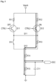
- FIG. 1 is a circuit diagram of a battery pack voltage measurement circuit according to an embodiment of the present invention.
- a battery pack voltage measurement circuit includes a first branching unit 100, a second branching unit 200, a relay unit 300, and a voltage distribution unit 400 connected between a battery pack voltage input terminal, that is, a power terminal Vpack and a ground terminal GND. More specifically, the battery pack voltage measurement circuit according to an embodiment of the present invention includes first and second branching units 100 and 200 connected in parallel between a power terminal Vpack and a first node Q11, a relay unit 300 connected between the first node Q11 and a second node Q12, and a voltage distribution unit 400 connected between the second node Q12 and a ground terminal GND.
- the first and second branching units 100 and 200 set a path of a current input from the power terminal Vpack to first and second paths.
- the relay unit 300 includes a relay switch S13 and a relay resistor, that is, a third resistor R13 connected in parallel, and the measurement of a battery pack voltage is performed and stopped by an on/off operation of a relay switch S13.
- the voltage distribution unit 400 divides and outputs a voltage of a current input through the first path or the second path in order to measure a voltage output to an output terminal DEC.
- the first branching unit 100 is connected between the power terminal Vpack and the first node Q11, and is connected in parallel with the second branching unit 200.
- the first branching unit 100 may include a first resistor R11 and a first switch S11 connected in series between the power terminal Vpack and the first node Q11. That is, the first resistor R11 and the first switch S11 are connected in series between the power terminal Vpack and the first node Q11 to form the first branching unit 100.
- the first branching unit 100 sets a current to flow in the first path through the first branching unit 100 according to a battery pack voltage.
- the first branching unit 100 is driven so that a current flows in the first path through the first branching unit 100.
- the first voltage of the battery pack may be 400 V. That is, when the battery pack voltage is 400 V, a current flows through the first branching unit 100.
- the first switch S11 may be an FET driven according to a first control signal CTRL1 of a control unit (not shown).
- the control unit When the battery pack voltage is the first voltage, that is, 400 V, the control unit generates the first control signal CTRL1, and accordingly, the first switch S11 is driven so that a current flows through the first branching unit 100.
- the first control signal CTRL1 is output at a logic high level to drive the first switch S11.
- the first control signal CTRL1 is not generated, and thus the first switch S11 is turned off.
- the first control signal CTRL1 is output at a logic low level to turn off the first switch S11.
- the first branching unit 100 drops down the battery pack voltage and supplies the voltage to the relay unit 300. That is, the first branching unit 100 drops the battery pack voltage of 400 V by the first resistor R11 and supplies the voltage to the relay unit 300. Therefore, even when the battery pack voltage of 400 V is applied to the power terminal Vpack, the voltage dropped by the first resistor R11 is applied to the relay unit 300.
- the battery pack voltage measurement circuit of the present invention supplies a voltage of 400V to the voltage distribution unit 400 through the first branching unit 100, and outputs the voltage after dividing the voltage by 100:1, for example.
- the first resistor R11 may have a resistance value of a predetermined ratio with fourth and fifth resistors R14 and R15 of the voltage distribution unit 400. For example, if the fourth resistor R14 is 1 M ⁇ and the fifth resistor R15 is 20 K ⁇ , the first resistor R11 may have a resistance value of 1 M ⁇ .
- the first resistor R11 has a resistance value of a predetermined ratio with the fourth and fifth resistors R14 and R15, so that the voltage of 400 V through the first branching unit 100 may be divided by 100:1 and output to the output terminal DEC.
- the second branching unit 200 is connected between the power supply terminal Vpack and the first node Q11, and is connected in parallel with the first branching unit 100.
- the second branching unit 200 may include a second resistor R12 and a second switch S12 connected in series between the power supply terminal Vpack and the first node Q11. That is, the second resistor R12 and the second switch S12 are connected in series between the power terminal Vpack and the first node Q11 to form the second branching unit 200.
- the second branching unit 200 sets a current to flow in the second path through the second branching unit 200 according to a battery pack voltage.
- the second branching unit 200 is driven so that a current flows in the second path through the second branching unit 200.
- the second voltage of the battery pack may be 800 V. That is, when the battery pack voltage is 800V, a current flows through the second branching unit 200.
- the second switch S12 may be an FET driven according to a second control signal CTRL2 of a control unit (not shown).
- the control unit When the battery pack voltage is the second voltage, that is, 800 V, the control unit generates a second control signal CTRL2, and accordingly, the second switch S12 is driven so that a current flows through the second branching unit 200.
- the second control signal CTRL2 is output at a logic high level to drive the second switch S12.
- the second control signal CTRL2 is not generated, and thus the second switch S12 is turned off.
- the second control signal CTRL2 is output at a logic low level to turn off the second switch S12.
- the second branching unit 200 drops the battery pack voltage and supplies the voltage to the relay unit 300. That is, the second branching unit 200 drops the battery pack voltage of 800 V by the second resistor R12 and supplies the voltage to the relay unit 300. Therefore, even when the battery pack voltage of 800 V is applied to the power terminal Vpack, the voltage dropped by the second resistor R12 is applied to the relay unit 300.
- the battery pack voltage measurement circuit of the present invention supplies 800 V voltage to the voltage distribution unit 400 through the second branching unit 200, and outputs the voltage after dividing the voltage by 200:1.
- the second resistor R12 may have a resistance value of a predetermined ratio with the fourth and fifth resistors R14 and R15 of the voltage distribution unit 400. For example, if the fourth resistor R14 is 1 M ⁇ and the fifth resistor R15 is 20 K ⁇ , the second resistor R12 may have a resistance value of 3 M ⁇ .
- the first resistor R11 has a resistance value of a predetermined ratio with the fourth and fifth resistors R14 and R15, so that the voltage of 800 V through the second branching unit 200 may be divided by 200:1 and output to the output terminal DEC.
- the relay unit 300 is connected between the first node Q11 and the second node Q12. That is, the relay unit 300 is provided between the first and second branching units 100 and 200 and the voltage distribution unit 400 connected in parallel.
- the relay unit 300 may include a third switch, that is, the relay switch S13 and a third resistor, that is, the relay resistor R13. At this time, the relay switch S13 and the relay resistor R13 are connected in parallel between the first node Q11 and the second node Q13.
- the relay switch S13 is driven by a control signal (not shown) for measuring a battery pack voltage and provides a voltage through the first branching unit 100 or the second branching unit 200 to the voltage distribution unit 400.
- the relay switch S13 when a control signal (not shown) is generated to measure a battery pack voltage and applied to the relay switch S13, the relay switch S13 is turned on to provide a voltage through the first branching unit 100 or the second branching unit 200 to the voltage distribution unit 400.
- the relay switch S13 is not shown in detail in the drawings, but may be composed of a solenoid and a switch. An on/off operation of the relay switch S13 may be controlled on the basis of a magnetic force generated in the solenoid.
- the relay resistor R13 is connected in parallel with the relay switch S13, so that when the relay switch S13 is turned off, a voltage applied to opposite ends of the relay switch S13 is the same as a voltage applied to opposite ends of the relay resistor R13.
- the present invention has an effect applicable to a voltage of 800 V with a relay rated at, for example, 400 V since by connecting the relay resistor R13 in parallel with the relay switch S13, only a low level battery pack voltage, which is a part of a battery pack voltage, is applied even when the relay switch S13 is turned off due to the relay resistor R13.
- the relay switch S13 since a voltage dropped by the first branching unit 100 or the second branching unit 200 is applied to one side of the relay switch S13, the relay switch S13 may be designed as a low-end relay element. Moreover, since a voltage dropped by the first branching unit 100 or the second branching unit 200 and the relay resistor R13 is applied to the other side of the relay switch S13, a stable on/off operation may be guaranteed even when the relay switch S13 is used as a low-specification relay switch.
- a resistance value of the relay resistor R13 may be determined to satisfy Equation 1 below.
- Equation 1 is an equation excluding an ADC output circuit, that is, the fifth resistor R15.
- R12, R13, and R14 are respectively resistance values of the second resistor R12, the relay resistor R13, and the fourth resistor R14
- V lim is an allowable voltage value of the relay switch S13
- Vo means a voltage of a battery pack.
- the second resistor R12 of the second branching unit 200 is greater than the first resistor R11 of the first branching unit 100, a resistance value of the relay resistor R13 in Equation 1 is affected by a resistance value of the second resistor R12.
- an allowable voltage value V lim of a relay switch S13 should be smaller than a voltage value Vo of a battery pack.
- the voltage value Vo of the battery pack is reduced by respective resistance values of the second resistor R12, the relay resistor R13, and the fourth resistor R14. Therefore, even when the voltage value Vo of the battery pack increases, for example, from 400 V to 800 V, the allowable voltage value V lim of the relay switch S13 may be satisfied if the resistance values of the second resistor R12, relay resistor R13, and fourth resistor R14 are appropriately designed.
- the fact that the allowable voltage value V lim of the relay switch S13 is satisfied means that even when the relay switch S13 of low specification is used, it is possible to stably measure the voltage Vo of the battery pack having a high voltage.
- the relay switch S13 is turned off, a voltage dropped by the first resistor or the second resistor R11 or R12 is applied to one end of the relay switch S13, and a voltage which is the same as a voltage applied to opposite ends of the relay resistor R13 is applied to opposite ends of the relay switch S13. Therefore, even when the relay switch S13 is used with a low specification, it is possible to stably perform an off operation of the relay switch S13.
- the battery pack voltage measurement circuit provides an environment in which it is possible to use the relay switch S13 with a low specification.
- a resistance value of the relay resistor R13 is determined to satisfy Equation 2 below.
- Equation 2 is an equation including an ADC output circuit, that is, the fifth resistor R13.
- R12, R13, R14, and R15 are respectively resistance values of the second resistor R12, the relay resistor R13, the fourth resistor R14, and the fifth resistor R15
- V lim is an allowable voltage value of the relay switch S13
- Vo means a voltage of a battery pack.
- Equation 2 like Equation 1, the allowable voltage value V lim of the relay switch S13 may be smaller than the voltage value Vo of the battery pack, and the voltage value Vo of the battery pack is applied with a voltage drop by resistance values of the second resistor R12, the relay resistor R13, the fourth resistor R14, and the fifth resistor R15.
- the voltage value (Vo) of the battery pack may be controlled to be lower by the resistance value of the fifth resistor R15, which means that even when becoming higher, the voltage value (Vo) of the battery pack may be included in the allowable voltage value (V lim ) of the relay switch S13.
- the relay switch S13 since in the battery pack voltage measurement circuit according to the embodiment of the present invention, it is possible to use the relay switch S13 with a low specification, it is possible to mass-produce the battery pack voltage measurement circuit at a lower manufacturing cost.
- it is possible to control the battery pack voltage measurement circuit by the first and second switches S11 and S12 of the first and second branching units 100 and 200 of the present invention it is possible to prevent occurrence of a leakage current due to the relay resistor R13 even when the relay switch S13 is turned off. That is, when the relay switch S13 is turned off, the first and second switches S11 and S12 also remain off, so that it is possible to prevent occurrence of a leakage current due to the relay resistor R13.
- the voltage distribution unit 400 is connected between the second node Q12 and the ground terminal GND.
- the voltage distribution unit 400 divides and outputs a voltage of a current input through the first path or the second path to measure a voltage output to the output terminal DEC. That is, the voltage distribution unit 400 divides a battery pack voltage Vpack supplied through the first branching unit 100 and the relay unit 300 and outputs the voltage to the output terminal DEC, and divides a battery pack voltage Vpack supplied through the second branching unit 200 and the relay unit 300 and outputs the voltage to the output terminal DEC.
- the battery pack voltage supplied through the first branching unit 100 is 400 V
- the battery pack voltage supplied through the second branching unit 200 is 800 V. That is, the voltage distribution unit 400 divides the battery pack voltage of 400V or 800V and outputs the voltage to the output terminal DEC.
- the voltage distribution unit 400 may include the fourth and fifth resistors R14 and R15 connected in series between the second node Q12 and the ground terminal GND.
- the output terminal DEC is provided between the fourth and fifth resistors 14 and 15. That is, the fourth resistor R14 is connected between the second node Q12 and the output terminal DEC, and the fifth resistor R15 is connected between the output terminal DEC and the ground terminal GND to form the voltage distribution unit 400.
- the voltage distribution unit 400 divides the battery pack voltage through the fourth and fifth resistors R14 and R15 and outputs the voltage to the output terminal DEC. Meanwhile, a capacitor C11 connected in parallel with the fifth resistor R15 is provided at the output terminal DEC.
- the fourth and fifth resistors R14 and R15 may have predetermined resistance values. That is, the fourth and fifth resistors R14 and R15 may have resistance values having a predetermined ratio with resistance values of the first and second resistors R11 and R12. For example, the fourth resistor R14 may have a resistance value of 1 M ⁇ , and the fifth resistor R15 may have a resistance value of 20 K ⁇ .
- the first resistor R11 may have a resistance value of, for example, 1 M ⁇
- the second resistor R12 may have a resistance value of, for example, 3 M ⁇ .
- the fourth and fifth resistors have a resistance value of a predetermined ratio with the first and second resistors R11 and R12, respectively, so that the voltage of 400 V through the first branching unit 100 may be divided by 100:1 and the voltage of 800 V through the second branching unit 200 may be divided to be output to the output terminal DEC.
- the present invention has an effect applicable to a voltage of 800 V with a relay rated at, for example, 400 V since by connecting the relay resistor R13 in parallel with the relay switch S13, only a low level battery pack voltage, which is a part of a battery pack voltage, is applied even when the relay switch S13 is turned off due to the relay resistor R13.
- a battery pack voltage is branched through the first and second branching units 100 and 200, it is possible to measure two different battery pack voltages. That is, since a battery pack voltage of 400 V is branched through the first branching unit 100 and a battery pack voltage of 800 V is branched through the second branching unit 200, it is possible to measure the battery pack voltage of 400 V or 800 V by using one battery pack voltage measurement circuit. Therefore, it is possible to use one battery pack voltage measurement circuit for a system to which a 400 V battery pack is applied and a system to which an 800 V battery pack is applied, and accordingly, there is no need to develop different battery pack voltage measurement circuits, thereby reducing product development costs and the like.
- FIGS. 2 to 4 are circuit diagrams showing a current flow to explain a driving method of a battery pack voltage measurement circuit according to an embodiment of the present invention. That is, FIG. 2 is a circuit diagram showing a current flow when a battery pack voltage is 400 V, FIG. 3 is a circuit diagram showing a current flow when a battery pack voltage is 800 V, and FIG. 4 is a circuit diagram for explaining a driving method when switches are turned off.
- a relay switch S13 may be turned on by a predetermined control signal to measure a battery pack voltage.
- a control unit (not shown) may output a first control signal CTRL1 or a second control signal CTRL2 according to a battery pack voltage, and when the battery pack voltage is, for example, 400 V, the first control signal CTRL1 may be output at a high level and the second control signal CTRL2 may be output at a low level.
- a first switch S11 is turned on by the high-level first control signal CTRL1 a current according to the battery pack voltage flows through a first path, that is, a first branching unit 100.
- the battery pack voltage of 400 V is supplied to a relay unit 300 through the first path and then supplied to a voltage distribution unit 400.
- a voltage drop occurs through the first branching unit 100 and the relay unit 300, and the voltage distribution unit 400 divides the dropped battery pack voltage and outputs the voltage to an output terminal DEC.
- a first resistor R11, a fourth resistor R14, and a fifth resistor R15 have predetermined resistance values, and accordingly, the battery pack voltage is dropped by, for example, 100:1 and output to the output terminal DEC.
- the first, fourth, and fifth resistors R11, R14, and R15 may have resistance values of 1 M ⁇ , 1 M ⁇ , and 20 K ⁇ , respectively.
- the battery pack voltage of 400 V may be dropped and divided through the first branching unit 100, the relay unit 300, and the voltage distribution unit 400 and output to the output terminal DEC, and an output value of the output terminal DEC may be input to an analog to digital converter of a control unit (not shown), that is, an MCU.
- the relay switch S13 may be turned on by a predetermined control signal to measure the battery pack voltage.
- a control unit (not shown) may output the first control signal CTRL1 or the second control signal CTRL2 according to the battery pack voltage, and when the battery pack voltage is, for example, 800 V, the second control signal CTRL2 may be output at a high level and the first control signal CTRL1 may be output at a low level.
- a second switch S12 is turned on by the second control signal CTRL2 at a high level, a current according to the battery pack voltage flows through a second path, that is, a second branching unit 200.
- the battery pack voltage of 800 V is supplied to the relay unit 300 through the second path and then supplied to the voltage distribution unit 400.
- a voltage drop occurs through the second branching unit 200 and the relay unit 300, and the voltage distribution unit 400 divides the dropped battery pack voltage and outputs the voltage to the output terminal DEC.
- a second resistor R12, the fourth resistor R14, and the fifth resistor R15 have predetermined resistance values, and accordingly, the battery pack voltage is dropped by, for example, 200:2 and output to the output terminal DEC.
- the second, fourth, and fifth resistors R12, R14, and R15 may have resistance values of 3 M ⁇ , 1 M ⁇ , and 20 K ⁇ , respectively.
- the battery pack voltage of 800 V may be dropped and divided through the second branching unit 200, the relay unit 300, and the voltage distribution unit 400 and output to the output terminal DEC, and an output value of the output terminal DEC may be input to an analog to digital converter of a control unit (not shown), that is, an MCU.
- the relay switch S13 when the battery pack voltage is not measured, the relay switch S13 may be turned off by a predetermined control signal.
- the first and second control signals CTRL1 and CTRL2 may be output in a low state as the relay switch S13 is turned off. Accordingly, the first and second switches S11 and S12 may be turned off. As the relay switch S13 and the first and second switches S11 and S12 are all turned off, it is possible to prevent a leakage current due to the relay resistor R13.
- a leakage current may occur through the relay resistor R13 when the relay switch S13 is turned off, but when the relay switch S13 is turned off, the first and second switches S11 and S12 also remain off, so that it is possible to prevent occurrence of a leakage current due to the resistor R13.
Landscapes
- Physics & Mathematics (AREA)
- General Physics & Mathematics (AREA)
- Engineering & Computer Science (AREA)
- Power Engineering (AREA)
- Measurement Of Current Or Voltage (AREA)
Abstract
Description
- The present invention relates to a battery pack voltage measurement circuit, and more particularly, to a battery pack voltage measurement circuit that measures a voltage of a battery pack and outputs a resultant value.
- Secondary batteries that can be charged and discharged, that is, batteries, are widely used as energy sources for mobile devices such as smart phones. In addition, batteries are also used as energy sources for eco-friendly vehicles such as electric vehicles and hybrid electric vehicles, which are proposed as a solution to air pollution caused by gasoline vehicles and diesel vehicles using fossil fuels. The types of applications using batteries are becoming very diverse, and it is expected that in the future batteries will be applied to more fields and products than now.
- Such a battery is generally used in the form of a battery pack rather than being used as a single battery cell. A battery pack includes at least one battery module, and the battery module may include a plurality of battery cells. In addition, battery packs are being developed with high-capacity and high-voltage specifications to be used longer and driven more powerfully according to consumer demand.
- The high-voltage specification of a battery pack provides more powerful driving power to power consuming devices such as electric vehicles using the battery pack. However, since the internal characteristics and internal resistance of battery cells constituting a battery pack are different, a voltage deviation may occur between the battery cells as a high voltage battery is continuously charged and discharged. When voltage deviations between battery cells are accumulated, the battery cells may be overcharged or overdischarged and thus cause fatal damage to a high voltage battery. In addition, when the lifespan of battery cells constituting a battery pack is reduced or the performance thereof is degraded, the performance of the battery pack may be deteriorated. Therefore, in order to monitor and manage the performance of a battery pack, it is necessary to accurately measure the voltage of the battery pack, which determines the performance of the battery pack. To this end, the battery pack includes a battery pack voltage measurement circuit.
- The battery pack voltage measurement circuit includes a relay switch and an analog to digital converting (ADC) output circuit. Here, the relay switch performs an on/off operation on the basis of an overcurrent, and the ADC output circuit measures the voltage of the battery pack according to a current flowing through the relay switch.
- Meanwhile, the voltage of a battery pack used in an electric vehicle tends to increase from 400 V to 800 V. Therefore, the battery pack voltage measurement circuit should also be designed suitably for the increased voltage of the battery pack. For this, the relay switch composed in the battery pack voltage measurement circuit should satisfy an allowable voltage value of 800 V. However, in the case of a relay switch that stably operates at an allowable voltage of 800 V, an advanced process technology and high-quality materials should be used, and thus a very high price relay switch, that is, a high-specification relay switch is required. When an existing low-specification relay switch having an allowable voltage value of 400 V is used to measure the voltage of a battery pack of 800 V, various problems may occur because the off point of the relay switch may be delayed.
- In order to use a low-specification relay switch, a battery pack voltage measurement circuit may be configured by connecting a low-specification relay switch and relay resistor in parallel. That is, a battery pack voltage measurement circuit may be configured in a manner in which a first resistor, a relay circuit, a second resistor, and an ADC output circuit are connected in series between a ground terminal and a power terminal of the battery pack and the relay circuit is provided with a relay element and relay resistor connected in parallel. Such a battery pack voltage measurement circuit has the advantage of enabling to use a 400 V rated relay switch even in an 800 V battery pack by adding a relay resistor in parallel with a relay switch. However, there is a problem in that a leakage current occurs through the relay resistor even after the relay switch is turned off. In addition, since first and second resistors are set to a resistance ratio of 800 V, measurement accuracy is degraded when measuring a battery pack voltage of 400 V having a resistance ratio higher than this.
- Prior art related to this includes the following document.
Korean Patent Registration No. 10-2041869 - The present invention provides a battery pack voltage measurement circuit capable of measuring a high voltage by using a low-specification relay switch.
- The present invention provides a battery pack voltage measurement circuit capable of preventing a leakage current even when using a low-specification relay switch.
- A battery pack voltage measurement circuit according to an example of the present invention includes: a relay unit performing battery pack voltage measurement; first and second branching units provided between a battery pack voltage input terminal and the relay unit, and branching a battery pack voltage into different paths according to the battery pack voltage and then supplying the branched voltage to the relay unit; and a voltage distribution unit dividing the battery pack voltage supplied through the first or second branching unit and the relay unit and outputting the divided battery pack voltage to an output terminal.
- The first branching unit includes a first resistor and a first switch connected in series between the battery pack voltage input terminal and the relay unit.
- The second branching unit includes a second resistor and a second switch connected in series between the battery pack voltage input terminal and the relay unit and connected in parallel with the first resistor and the first switch, respectively.
- The relay unit includes a relay switch and a third resistor connected in parallel between a connection point of the first and second branching units and the voltage distribution unit.
- The battery pack voltage measurement circuit further includes a control unit for controlling the first switch, the second switch, and the relay switch.
- The control unit selectively opens and closes the first and second switches according to the magnitude of the battery pack voltage.
- A first resistance ratio, which is a ratio between the sum of resistors of the voltage distribution unit and the first resistor, and a second resistance ratio, which is a ratio between the sum of resistors of the voltage distribution unit and the second resistor, are set to be different from each other.
- A battery pack voltage measurement circuit according to another example of the present invention includes: a first branching unit provided between a battery pack voltage input terminal and a first node to branch a first battery pack voltage; a second branching unit provided between the battery pack voltage input terminal and the first node and connected in parallel with the first branching unit to branch a second battery pack voltage; a relay unit disposed between the first node and a second node and controlling measurement of a battery pack voltage according to a switching operation; and a voltage distribution unit provided between the second node and a ground terminal, and dividing a battery pack voltage supplied through the first or second branching unit and the relay unit and then outputting the voltage to an output terminal.
- The first branching unit includes a first resistor and a first switch connected in series between the battery pack voltage input terminal and the first node.
- The second branching unit includes a second resistor and a second switch connected in series between the battery pack voltage input terminal and the first node and connected in parallel with the first resistor and the first switch, respectively.
- The relay unit includes a relay switch and a third resistor connected in parallel between the first node and the second node.
- The battery pack voltage measurement circuit further includes a control unit for controlling the first switch, the second switch, and the relay switch.
- The control unit selectively opens and closes the first and second switches according to the magnitude of the battery pack voltage.
- Resistance values of the first resistor and the second resistor are different from each other.
- It is possible to mass-produce a battery pack voltage measurement circuit according to an embodiment of the present invention at a lower manufacturing cost because it is possible to use a relay switch with a low specification. That is, the present invention has an effect applicable to a voltage of 800 V with a relay rated at, for example, 400 V since by connecting a relay resistor in parallel with a relay switch, only a low level battery pack voltage, which is a part of a battery pack voltage, is applied even when the relay switch is turned off due to the relay resistor.
- In addition, in the present invention, since a battery pack voltage is branched through first and second branching units, it is possible to measure two different battery pack voltages. That is, since a battery pack voltage of 400 V is branched through the first branching unit and a battery pack voltage of 800 V is branched through the second branching unit, it is possible to measure the battery pack voltage of 400 V or 800 V by using one battery pack voltage measurement circuit. Therefore, it is possible to use one battery pack voltage measurement circuit for a system to which a 400 V battery pack is applied and a system to which an 800 V battery pack is applied, and accordingly, there is no need to develop different battery pack voltage measurement circuits, thereby reducing product development costs and the like.
- In addition, since it is possible to control a battery pack voltage measurement circuit by first and second switches of the first and second branching units of the present invention, it is possible to prevent occurrence of a leakage current due to a relay resistor even when a relay switch is turned off. That is, assuming that there are no first and second switches, a leakage current may occur through a relay resistor when a relay switch is turned off, but when the relay switch is turned off, first and second switches also remain off, so that it is possible to prevent occurrence of a leakage current.
-
-
FIG. 1 is a circuit diagram of a battery pack voltage measurement circuit according to an embodiment of the present invention. -
FIGS. 2 to 4 are circuit diagrams showing a current flow to explain a driving method of a battery pack voltage measurement circuit according to an embodiment of the present invention. - Hereinafter, embodiments of the present invention will be described in detail with reference to the accompanying drawings. However, the present invention is not limited to the embodiments disclosed below, but will be implemented in various different forms, and these embodiments are provided merely to make the disclosure of the present invention complete, and to allow those skilled in the art to fully know the scope of the invention.
-
FIG. 1 is a circuit diagram of a battery pack voltage measurement circuit according to an embodiment of the present invention. - Referring to
FIG. 1 , a battery pack voltage measurement circuit according to an embodiment of the present invention includes afirst branching unit 100, asecond branching unit 200, arelay unit 300, and avoltage distribution unit 400 connected between a battery pack voltage input terminal, that is, a power terminal Vpack and a ground terminal GND. More specifically, the battery pack voltage measurement circuit according to an embodiment of the present invention includes first andsecond branching units relay unit 300 connected between the first node Q11 and a second node Q12, and avoltage distribution unit 400 connected between the second node Q12 and a ground terminal GND. Here, the first andsecond branching units relay unit 300 includes a relay switch S13 and a relay resistor, that is, a third resistor R13 connected in parallel, and the measurement of a battery pack voltage is performed and stopped by an on/off operation of a relay switch S13. Moreover, thevoltage distribution unit 400 divides and outputs a voltage of a current input through the first path or the second path in order to measure a voltage output to an output terminal DEC. The battery pack voltage measurement circuit according to the embodiment of the present invention will be described in more detail for each component as follows. - The first branching
unit 100 is connected between the power terminal Vpack and the first node Q11, and is connected in parallel with the second branchingunit 200. The first branchingunit 100 may include a first resistor R11 and a first switch S11 connected in series between the power terminal Vpack and the first node Q11. That is, the first resistor R11 and the first switch S11 are connected in series between the power terminal Vpack and the first node Q11 to form the first branchingunit 100. The first branchingunit 100 sets a current to flow in the first path through the first branchingunit 100 according to a battery pack voltage. That is, when a first current according to a first voltage is applied from the power terminal Vpack, the first branchingunit 100 is driven so that a current flows in the first path through the first branchingunit 100. Here, the first voltage of the battery pack may be 400 V. That is, when the battery pack voltage is 400 V, a current flows through the first branchingunit 100. - The first switch S11 may be an FET driven according to a first control signal CTRL1 of a control unit (not shown). When the battery pack voltage is the first voltage, that is, 400 V, the control unit generates the first control signal CTRL1, and accordingly, the first switch S11 is driven so that a current flows through the first branching
unit 100. For example, when the battery pack voltage is 400 V, the first control signal CTRL1 is output at a logic high level to drive the first switch S11. Of course, when the battery pack voltage is a second voltage higher than the first voltage, the first control signal CTRL1 is not generated, and thus the first switch S11 is turned off. For example, when the battery pack voltage is 800 V, the first control signal CTRL1 is output at a logic low level to turn off the first switch S11. In addition, the first branchingunit 100 drops down the battery pack voltage and supplies the voltage to therelay unit 300. That is, the first branchingunit 100 drops the battery pack voltage of 400 V by the first resistor R11 and supplies the voltage to therelay unit 300. Therefore, even when the battery pack voltage of 400 V is applied to the power terminal Vpack, the voltage dropped by the first resistor R11 is applied to therelay unit 300. - Meanwhile, the battery pack voltage measurement circuit of the present invention supplies a voltage of 400V to the
voltage distribution unit 400 through the first branchingunit 100, and outputs the voltage after dividing the voltage by 100:1, for example. Accordingly, the first resistor R11 may have a resistance value of a predetermined ratio with fourth and fifth resistors R14 and R15 of thevoltage distribution unit 400. For example, if the fourth resistor R14 is 1 MΩ and the fifth resistor R15 is 20 KΩ, the first resistor R11 may have a resistance value of 1 MΩ. In this way, the first resistor R11 has a resistance value of a predetermined ratio with the fourth and fifth resistors R14 and R15, so that the voltage of 400 V through the first branchingunit 100 may be divided by 100:1 and output to the output terminal DEC. - The second branching
unit 200 is connected between the power supply terminal Vpack and the first node Q11, and is connected in parallel with the first branchingunit 100. The second branchingunit 200 may include a second resistor R12 and a second switch S12 connected in series between the power supply terminal Vpack and the first node Q11. That is, the second resistor R12 and the second switch S12 are connected in series between the power terminal Vpack and the first node Q11 to form the second branchingunit 200. The second branchingunit 200 sets a current to flow in the second path through the second branchingunit 200 according to a battery pack voltage. That is, when a second current according to the second voltage is applied from the power terminal Vpack, the second branchingunit 200 is driven so that a current flows in the second path through the second branchingunit 200. Here, the second voltage of the battery pack may be 800 V. That is, when the battery pack voltage is 800V, a current flows through the second branchingunit 200. - The second switch S12 may be an FET driven according to a second control signal CTRL2 of a control unit (not shown). When the battery pack voltage is the second voltage, that is, 800 V, the control unit generates a second control signal CTRL2, and accordingly, the second switch S12 is driven so that a current flows through the second branching
unit 200. For example, when the battery pack voltage is 800 V, the second control signal CTRL2 is output at a logic high level to drive the second switch S12. Of course, when the battery pack voltage is the first voltage lower than the second voltage, the second control signal CTRL2 is not generated, and thus the second switch S12 is turned off. For example, when the battery pack voltage is 400 V, the second control signal CTRL2 is output at a logic low level to turn off the second switch S12. In addition, the second branchingunit 200 drops the battery pack voltage and supplies the voltage to therelay unit 300. That is, the second branchingunit 200 drops the battery pack voltage of 800 V by the second resistor R12 and supplies the voltage to therelay unit 300. Therefore, even when the battery pack voltage of 800 V is applied to the power terminal Vpack, the voltage dropped by the second resistor R12 is applied to therelay unit 300. - Meanwhile, the battery pack voltage measurement circuit of the present invention supplies 800 V voltage to the
voltage distribution unit 400 through the second branchingunit 200, and outputs the voltage after dividing the voltage by 200:1. Accordingly, the second resistor R12 may have a resistance value of a predetermined ratio with the fourth and fifth resistors R14 and R15 of thevoltage distribution unit 400. For example, if the fourth resistor R14 is 1 MΩ and the fifth resistor R15 is 20 KΩ, the second resistor R12 may have a resistance value of 3 MΩ. In this way, the first resistor R11 has a resistance value of a predetermined ratio with the fourth and fifth resistors R14 and R15, so that the voltage of 800 V through the second branchingunit 200 may be divided by 200:1 and output to the output terminal DEC. - The
relay unit 300 is connected between the first node Q11 and the second node Q12. That is, therelay unit 300 is provided between the first and second branchingunits voltage distribution unit 400 connected in parallel. Therelay unit 300 may include a third switch, that is, the relay switch S13 and a third resistor, that is, the relay resistor R13. At this time, the relay switch S13 and the relay resistor R13 are connected in parallel between the first node Q11 and the second node Q13. The relay switch S13 is driven by a control signal (not shown) for measuring a battery pack voltage and provides a voltage through the first branchingunit 100 or the second branchingunit 200 to thevoltage distribution unit 400. That is, when a control signal (not shown) is generated to measure a battery pack voltage and applied to the relay switch S13, the relay switch S13 is turned on to provide a voltage through the first branchingunit 100 or the second branchingunit 200 to thevoltage distribution unit 400. - The relay switch S13 is not shown in detail in the drawings, but may be composed of a solenoid and a switch. An on/off operation of the relay switch S13 may be controlled on the basis of a magnetic force generated in the solenoid. In addition, the relay resistor R13 is connected in parallel with the relay switch S13, so that when the relay switch S13 is turned off, a voltage applied to opposite ends of the relay switch S13 is the same as a voltage applied to opposite ends of the relay resistor R13.
- Meanwhile, in the case of the prior art without the relay resistor R13, when the relay switch S13 is turned off, most of a battery pack voltage is applied to opposite ends of the relay switch S13, so that a higher rated relay may be required if the battery pack voltage is a high voltage of 800 V, for example. However, the present invention has an effect applicable to a voltage of 800 V with a relay rated at, for example, 400 V since by connecting the relay resistor R13 in parallel with the relay switch S13, only a low level battery pack voltage, which is a part of a battery pack voltage, is applied even when the relay switch S13 is turned off due to the relay resistor R13. That is, since a voltage dropped by the first branching
unit 100 or the second branchingunit 200 is applied to one side of the relay switch S13, the relay switch S13 may be designed as a low-end relay element. Moreover, since a voltage dropped by the first branchingunit 100 or the second branchingunit 200 and the relay resistor R13 is applied to the other side of the relay switch S13, a stable on/off operation may be guaranteed even when the relay switch S13 is used as a low-specification relay switch. - In addition, since it is possible to control the battery pack voltage measurement circuit by the first and second switches S11 and S12 of the first and second branching
units - Meanwhile, a resistance value of the relay resistor R13 may be determined to satisfy Equation 1 below.

- Equation 1 is an equation excluding an ADC output circuit, that is, the fifth resistor R15. Here, R12, R13, and R14 are respectively resistance values of the second resistor R12, the relay resistor R13, and the fourth resistor R14, Vlim is an allowable voltage value of the relay switch S13, and Vo means a voltage of a battery pack. In addition, since the second resistor R12 of the second branching
unit 200 is greater than the first resistor R11 of the first branchingunit 100, a resistance value of the relay resistor R13 in Equation 1 is affected by a resistance value of the second resistor R12. - As shown in Equation 1, an allowable voltage value Vlim of a relay switch S13 should be smaller than a voltage value Vo of a battery pack. At this time, the voltage value Vo of the battery pack is reduced by respective resistance values of the second resistor R12, the relay resistor R13, and the fourth resistor R14. Therefore, even when the voltage value Vo of the battery pack increases, for example, from 400 V to 800 V, the allowable voltage value Vlim of the relay switch S13 may be satisfied if the resistance values of the second resistor R12, relay resistor R13, and fourth resistor R14 are appropriately designed. Here, even when the voltage value Vo of the battery pack is 800 V, the fact that the allowable voltage value Vlim of the relay switch S13 is satisfied means that even when the relay switch S13 of low specification is used, it is possible to stably measure the voltage Vo of the battery pack having a high voltage. In addition, when the relay switch S13 is turned off, a voltage dropped by the first resistor or the second resistor R11 or R12 is applied to one end of the relay switch S13, and a voltage which is the same as a voltage applied to opposite ends of the relay resistor R13 is applied to opposite ends of the relay switch S13. Therefore, even when the relay switch S13 is used with a low specification, it is possible to stably perform an off operation of the relay switch S13.
- As described above, through these configurations and operations, the battery pack voltage measurement circuit according to an embodiment of the present invention provides an environment in which it is possible to use the relay switch S13 with a low specification.
- Meanwhile, a resistance value of the relay resistor R13 is determined to satisfy Equation 2 below.

- Equation 2 is an equation including an ADC output circuit, that is, the fifth resistor R13. Here, R12, R13, R14, and R15 are respectively resistance values of the second resistor R12, the relay resistor R13, the fourth resistor R14, and the fifth resistor R15, Vlim is an allowable voltage value of the relay switch S13, and Vo means a voltage of a battery pack.
- Equation 2, like Equation 1, the allowable voltage value Vlim of the relay switch S13 may be smaller than the voltage value Vo of the battery pack, and the voltage value Vo of the battery pack is applied with a voltage drop by resistance values of the second resistor R12, the relay resistor R13, the fourth resistor R14, and the fifth resistor R15. In particular, in Equation 2, the voltage value (Vo) of the battery pack may be controlled to be lower by the resistance value of the fifth resistor R15, which means that even when becoming higher, the voltage value (Vo) of the battery pack may be included in the allowable voltage value (Vlim) of the relay switch S13.
- As described above, since in the battery pack voltage measurement circuit according to the embodiment of the present invention, it is possible to use the relay switch S13 with a low specification, it is possible to mass-produce the battery pack voltage measurement circuit at a lower manufacturing cost. In addition, since it is possible to control the battery pack voltage measurement circuit by the first and second switches S11 and S12 of the first and second branching
units - The
voltage distribution unit 400 is connected between the second node Q12 and the ground terminal GND. Thevoltage distribution unit 400 divides and outputs a voltage of a current input through the first path or the second path to measure a voltage output to the output terminal DEC. That is, thevoltage distribution unit 400 divides a battery pack voltage Vpack supplied through the first branchingunit 100 and therelay unit 300 and outputs the voltage to the output terminal DEC, and divides a battery pack voltage Vpack supplied through the second branchingunit 200 and therelay unit 300 and outputs the voltage to the output terminal DEC. At this time, the battery pack voltage supplied through the first branchingunit 100 is 400 V, and the battery pack voltage supplied through the second branchingunit 200 is 800 V. That is, thevoltage distribution unit 400 divides the battery pack voltage of 400V or 800V and outputs the voltage to the output terminal DEC. - The
voltage distribution unit 400 may include the fourth and fifth resistors R14 and R15 connected in series between the second node Q12 and the ground terminal GND. At this time, the output terminal DEC is provided between the fourth and fifth resistors 14 and 15. That is, the fourth resistor R14 is connected between the second node Q12 and the output terminal DEC, and the fifth resistor R15 is connected between the output terminal DEC and the ground terminal GND to form thevoltage distribution unit 400. Accordingly, thevoltage distribution unit 400 divides the battery pack voltage through the fourth and fifth resistors R14 and R15 and outputs the voltage to the output terminal DEC. Meanwhile, a capacitor C11 connected in parallel with the fifth resistor R15 is provided at the output terminal DEC. Meanwhile, the fourth and fifth resistors R14 and R15 may have predetermined resistance values. That is, the fourth and fifth resistors R14 and R15 may have resistance values having a predetermined ratio with resistance values of the first and second resistors R11 and R12. For example, the fourth resistor R14 may have a resistance value of 1 MΩ, and the fifth resistor R15 may have a resistance value of 20 KΩ. At this time, the first resistor R11 may have a resistance value of, for example, 1 MΩ, and the second resistor R12 may have a resistance value of, for example, 3 MΩ. In this way, the fourth and fifth resistors have a resistance value of a predetermined ratio with the first and second resistors R11 and R12, respectively, so that the voltage of 400 V through the first branchingunit 100 may be divided by 100:1 and the voltage of 800 V through the second branchingunit 200 may be divided to be output to the output terminal DEC. - As described above, since in the battery pack voltage measurement circuit according to the embodiment of the present invention, it is possible to use the relay switch S13 with a low specification, it is possible to mass-produce the battery pack voltage measurement circuit at a lower manufacturing cost. That is, the present invention has an effect applicable to a voltage of 800 V with a relay rated at, for example, 400 V since by connecting the relay resistor R13 in parallel with the relay switch S13, only a low level battery pack voltage, which is a part of a battery pack voltage, is applied even when the relay switch S13 is turned off due to the relay resistor R13. In addition, since it is possible to control the battery pack voltage measurement circuit by the first and second switches S11 and S12 of the first and second branching
units units unit 100 and a battery pack voltage of 800 V is branched through the second branchingunit 200, it is possible to measure the battery pack voltage of 400 V or 800 V by using one battery pack voltage measurement circuit. Therefore, it is possible to use one battery pack voltage measurement circuit for a system to which a 400 V battery pack is applied and a system to which an 800 V battery pack is applied, and accordingly, there is no need to develop different battery pack voltage measurement circuits, thereby reducing product development costs and the like. -
FIGS. 2 to 4 are circuit diagrams showing a current flow to explain a driving method of a battery pack voltage measurement circuit according to an embodiment of the present invention. That is,FIG. 2 is a circuit diagram showing a current flow when a battery pack voltage is 400 V,FIG. 3 is a circuit diagram showing a current flow when a battery pack voltage is 800 V, andFIG. 4 is a circuit diagram for explaining a driving method when switches are turned off. - Referring to
FIG. 2 , a relay switch S13 may be turned on by a predetermined control signal to measure a battery pack voltage. At this time, a control unit (not shown) may output a first control signal CTRL1 or a second control signal CTRL2 according to a battery pack voltage, and when the battery pack voltage is, for example, 400 V, the first control signal CTRL1 may be output at a high level and the second control signal CTRL2 may be output at a low level. When a first switch S11 is turned on by the high-level first control signal CTRL1, a current according to the battery pack voltage flows through a first path, that is, a first branchingunit 100. That is, when the first control signal is applied at a high level, the battery pack voltage of 400 V is supplied to arelay unit 300 through the first path and then supplied to avoltage distribution unit 400. At this time, a voltage drop occurs through the first branchingunit 100 and therelay unit 300, and thevoltage distribution unit 400 divides the dropped battery pack voltage and outputs the voltage to an output terminal DEC. Meanwhile, a first resistor R11, a fourth resistor R14, and a fifth resistor R15 have predetermined resistance values, and accordingly, the battery pack voltage is dropped by, for example, 100:1 and output to the output terminal DEC. In order to drop the battery pack voltage of 400 V by about 100: 1 and output the voltage, the first, fourth, and fifth resistors R11, R14, and R15 may have resistance values of 1 MΩ, 1 MΩ, and 20 KΩ, respectively. Eventually, the battery pack voltage of 400 V may be dropped and divided through the first branchingunit 100, therelay unit 300, and thevoltage distribution unit 400 and output to the output terminal DEC, and an output value of the output terminal DEC may be input to an analog to digital converter of a control unit (not shown), that is, an MCU. - Referring to
FIG. 3 , the relay switch S13 may be turned on by a predetermined control signal to measure the battery pack voltage. At this time, a control unit (not shown) may output the first control signal CTRL1 or the second control signal CTRL2 according to the battery pack voltage, and when the battery pack voltage is, for example, 800 V, the second control signal CTRL2 may be output at a high level and the first control signal CTRL1 may be output at a low level. When a second switch S12 is turned on by the second control signal CTRL2 at a high level, a current according to the battery pack voltage flows through a second path, that is, a second branchingunit 200. That is, when the second control signal is applied at a high level, the battery pack voltage of 800 V is supplied to therelay unit 300 through the second path and then supplied to thevoltage distribution unit 400. At this time, a voltage drop occurs through the second branchingunit 200 and therelay unit 300, and thevoltage distribution unit 400 divides the dropped battery pack voltage and outputs the voltage to the output terminal DEC. Meanwhile, a second resistor R12, the fourth resistor R14, and the fifth resistor R15 have predetermined resistance values, and accordingly, the battery pack voltage is dropped by, for example, 200:2 and output to the output terminal DEC. In order to drop the battery pack voltage of 800 V by about 200:1 and output the voltage, the second, fourth, and fifth resistors R12, R14, and R15 may have resistance values of 3 MΩ, 1 MΩ, and 20 KΩ, respectively. Eventually, the battery pack voltage of 800 V may be dropped and divided through the second branchingunit 200, therelay unit 300, and thevoltage distribution unit 400 and output to the output terminal DEC, and an output value of the output terminal DEC may be input to an analog to digital converter of a control unit (not shown), that is, an MCU. - Referring to
FIG. 4 , when the battery pack voltage is not measured, the relay switch S13 may be turned off by a predetermined control signal. At this time, in a control unit (not shown), the first and second control signals CTRL1 and CTRL2 may be output in a low state as the relay switch S13 is turned off. Accordingly, the first and second switches S11 and S12 may be turned off. As the relay switch S13 and the first and second switches S11 and S12 are all turned off, it is possible to prevent a leakage current due to the relay resistor R13. That is, assuming that there are no first and second switches S11 and S12, a leakage current may occur through the relay resistor R13 when the relay switch S13 is turned off, but when the relay switch S13 is turned off, the first and second switches S11 and S12 also remain off, so that it is possible to prevent occurrence of a leakage current due to the resistor R13. - Although the technical spirit of the present invention as described above has been specifically described according to the above embodiments, it should be noted that the above embodiments are for explanation and not for limitation. In addition, those skilled in the art will understand that various embodiments are possible within the scope of the technical spirit of the present invention.
- The names of the reference numerals used in the description and drawings of the present invention are as follows.
100 : First branching unit 200 : Second branching unit 300 : Relay unit 400 : Voltage distribution unit
Claims (14)
- A battery pack voltage measurement circuit, comprising:a relay unit controlling battery pack voltage measurement;first and second branching units provided between a battery pack voltage input terminal and the relay unit, and branching a battery pack voltage into different paths according to the battery pack voltage and then supplying the branched voltage to the relay unit; anda voltage distribution unit dividing the battery pack voltage supplied through the first or second branching unit and the relay unit and outputting the divided battery pack voltage to an output terminal.
- The battery pack voltage measurement circuit of claim 1, wherein the first branching unit comprises a first resistor and a first switch connected in series between the battery pack voltage input terminal and the relay unit.
- The battery pack voltage measurement circuit of claim 2, wherein the second branching unit comprises a second resistor and a second switch connected in series between the battery pack voltage input terminal and the relay unit and connected in parallel with the first resistor and the first switch, respectively.
- The battery pack voltage measurement circuit of claim 3, wherein the relay unit comprises a relay switch and a third resistor connected in parallel between a connection point of the first and second branching units and the voltage distribution unit.
- The battery pack voltage measurement circuit of claim 4, further comprising a control unit for controlling the first switch, the second switch, and the relay switch.
- The battery pack voltage measurement circuit of claim 5, wherein the control unit selectively opens and closes the first and second switches according to a magnitude of the battery pack voltage.
- The battery pack voltage measurement circuit of claim 4, wherein a first resistance ratio, which is a ratio between the sum of resistors of the voltage distribution unit and the first resistor, and a second resistance ratio, which is a ratio between the sum of resistors of the voltage distribution unit and the second resistor, are set to be different from each other.
- A battery pack voltage measurement circuit, comprising:a first branching unit provided between a battery pack voltage input terminal and a first node to branch a first battery pack voltage;a second branching unit provided between the battery pack voltage input terminal and the first node and connected in parallel with the first branching unit to branch a second battery pack voltage;a relay unit disposed between the first node and a second node and controlling measurement of a battery pack voltage according to a switching operation; anda voltage distribution unit provided between the second node and a ground terminal, and dividing a battery pack voltage supplied through the first or second branching unit and the relay unit and then outputting the voltage to an output terminal.
- The battery pack voltage measurement circuit of claim 8, wherein the first branching unit comprises a first resistor and a first switch connected in series between the battery pack voltage input terminal and the first node.
- The battery pack voltage measurement circuit of claim 9, wherein the second branching unit comprises a second resistor and a second switch connected in series between the battery pack voltage input terminal and the first node and connected in parallel with the first resistor and the first switch, respectively.
- The battery pack voltage measurement circuit of claim 10, wherein the relay unit comprises a relay switch and a third resistor connected in parallel between the first node and the second node.
- The battery pack voltage measurement circuit of claim 11, further comprising a control unit for controlling the first switch, the second switch, and the relay switch.
- The battery pack voltage measurement circuit of claim 12, wherein the control unit selectively opens and closes the first and second switches according to a magnitude of the battery pack voltage.
- The battery pack voltage measurement circuit of claim 11, wherein resistance values of the first resistor and the second resistor are different from each other.
Applications Claiming Priority (2)
| Application Number | Priority Date | Filing Date | Title |
|---|---|---|---|
| KR1020220167473A KR20240083388A (en) | 2022-12-05 | 2022-12-05 | measuring circuit for battery pack voltage |
| PCT/KR2023/010223 WO2024122784A1 (en) | 2022-12-05 | 2023-07-17 | Battery pack voltage measurement circuit |
Publications (2)
| Publication Number | Publication Date |
|---|---|
| EP4560333A1 true EP4560333A1 (en) | 2025-05-28 |
| EP4560333A4 EP4560333A4 (en) | 2026-03-25 |
Family
ID=91379527
Family Applications (1)
| Application Number | Title | Priority Date | Filing Date |
|---|---|---|---|
| EP23900806.3A Pending EP4560333A4 (en) | 2022-12-05 | 2023-07-17 | Voltage measuring circuit for battery pack |
Country Status (6)
| Country | Link |
|---|---|
| US (1) | US20260079186A1 (en) |
| EP (1) | EP4560333A4 (en) |
| JP (1) | JP2025527871A (en) |
| KR (1) | KR20240083388A (en) |
| CN (1) | CN119816742A (en) |
| WO (1) | WO2024122784A1 (en) |
Family Cites Families (9)
| Publication number | Priority date | Publication date | Assignee | Title |
|---|---|---|---|---|
| JP5893411B2 (en) * | 2012-01-06 | 2016-03-23 | 日置電機株式会社 | Voltage measuring apparatus and voltage measuring method |
| KR102041869B1 (en) | 2013-05-21 | 2019-11-08 | 엘지이노텍 주식회사 | Voltage measuring apparatus of battery pack and Battery control system |
| CN103344822A (en) * | 2013-06-26 | 2013-10-09 | 天津成科自动化工程技术有限公司 | Battery voltage monitoring circuit used for battery powered equipment |
| CN203350420U (en) * | 2013-06-26 | 2013-12-18 | 天津成科自动化工程技术有限公司 | Battery voltage monitoring circuit for battery powered equipment |
| JP6627732B2 (en) * | 2016-12-07 | 2020-01-08 | 株式会社デンソー | Power supply circuit device |
| KR102561395B1 (en) * | 2018-11-12 | 2023-08-01 | 삼성전자주식회사 | Electronic device and battery pack for selecting path for measuring voltage of battery cell |
| KR102804359B1 (en) * | 2020-04-13 | 2025-05-09 | 에스케이온 주식회사 | Apparatus for measuring insulation resistance |
| CN112578277B (en) * | 2020-12-03 | 2025-09-26 | 湖北亿纬动力有限公司 | Power battery system pre-charging relay adhesion detection system and detection method |
| KR20220153292A (en) * | 2021-05-11 | 2022-11-18 | 에스케이온 주식회사 | BMS and Battery System |
-
2022
- 2022-12-05 KR KR1020220167473A patent/KR20240083388A/en active Pending
-
2023
- 2023-07-17 JP JP2025513034A patent/JP2025527871A/en active Pending
- 2023-07-17 US US19/108,960 patent/US20260079186A1/en active Pending
- 2023-07-17 EP EP23900806.3A patent/EP4560333A4/en active Pending
- 2023-07-17 WO PCT/KR2023/010223 patent/WO2024122784A1/en not_active Ceased
- 2023-07-17 CN CN202380063426.9A patent/CN119816742A/en active Pending
Also Published As
| Publication number | Publication date |
|---|---|
| KR20240083388A (en) | 2024-06-12 |
| US20260079186A1 (en) | 2026-03-19 |
| WO2024122784A1 (en) | 2024-06-13 |
| CN119816742A (en) | 2025-04-11 |
| EP4560333A4 (en) | 2026-03-25 |
| JP2025527871A (en) | 2025-08-22 |
Similar Documents
| Publication | Publication Date | Title |
|---|---|---|
| US10186878B2 (en) | System and method for balancing the charge of a plurality of energy storage modules | |
| CN102735913B (en) | Voltage detection apparatus and combination circuit | |
| US20030062874A1 (en) | Circuit for adjusting charging rate of cells in combination | |
| US20120032681A1 (en) | Determination of the internal resistance of a battery cell of a traction battery while using resistive cell balancing | |
| US20230106428A1 (en) | Switch systems for rechargeable battery arrays | |
| US20240356345A1 (en) | Battery charging method and battery system for providing the same | |
| US20160252584A1 (en) | Voltage detection device, voltage detection method, abnormality determination device, abnormality determination method, and battery pack system | |
| EP1118869B1 (en) | Battery voltage detection apparatus and detection method | |
| JP2014081267A (en) | Electric power source device | |
| EP4318006A1 (en) | Battery pack voltage measurement circuit and operation method thereof | |
| CN113459892A (en) | Method for determining the state of charge of at least one traction battery of a motor vehicle | |
| US20260079186A1 (en) | Battery Pack Voltage Measurement Circuit | |
| KR20220023202A (en) | Contactor management method and battery system providing the same | |
| EP3940865A1 (en) | Battery system | |
| EP2045902A1 (en) | Power supply device | |
| US11398743B2 (en) | Apparatus and method for forming current path according to charging or discharging state of battery pack | |
| JP4163221B2 (en) | Power supply system and discharge control method thereof | |
| EP3573864A1 (en) | Battery unit and method for operating a battery unit | |
| US20250027984A1 (en) | Battery Apparatus and Battery Management System for Measuring Insulation Resistance | |
| CN103376413A (en) | Test system of battery and method for controlling test system of battery | |
| CN113447833B (en) | A battery voltage detection circuit | |
| EP4207548A1 (en) | Battery management apparatus and operation method therefor | |
| EP4160782B1 (en) | Battery disconnect unit including moving plate | |
| JP5157634B2 (en) | Voltage measuring apparatus and voltage measuring method | |
| JP3713470B2 (en) | Secondary battery charge / discharge controller |
Legal Events
| Date | Code | Title | Description |
|---|---|---|---|
| STAA | Information on the status of an ep patent application or granted ep patent |
Free format text: STATUS: THE INTERNATIONAL PUBLICATION HAS BEEN MADE |
|
| PUAI | Public reference made under article 153(3) epc to a published international application that has entered the european phase |
Free format text: ORIGINAL CODE: 0009012 |
|
| STAA | Information on the status of an ep patent application or granted ep patent |
Free format text: STATUS: REQUEST FOR EXAMINATION WAS MADE |
|
| 17P | Request for examination filed |
Effective date: 20250220 |
|
| AK | Designated contracting states |
Kind code of ref document: A1 Designated state(s): AL AT BE BG CH CY CZ DE DK EE ES FI FR GB GR HR HU IE IS IT LI LT LU LV MC ME MK MT NL NO PL PT RO RS SE SI SK SM TR |
|
| REG | Reference to a national code |
Ref country code: DE Ref legal event code: R079 Free format text: PREVIOUS MAIN CLASS: G01R0031383500 Ipc: H02J0007800000 |
|
| DAV | Request for validation of the european patent (deleted) | ||
| DAX | Request for extension of the european patent (deleted) | ||
| A4 | Supplementary search report drawn up and despatched |
Effective date: 20260224 |
|
| RIC1 | Information provided on ipc code assigned before grant |
Ipc: H02J 7/80 20260101AFI20260217BHEP Ipc: H02J 7/64 20260101ALI20260217BHEP Ipc: G01R 31/3835 20190101ALI20260217BHEP Ipc: G01R 15/04 20060101ALI20260217BHEP |