EP4560325A1 - Clamp meter with rotating clamp jaw - Google Patents
Clamp meter with rotating clamp jaw Download PDFInfo
- Publication number
- EP4560325A1 EP4560325A1 EP24181167.8A EP24181167A EP4560325A1 EP 4560325 A1 EP4560325 A1 EP 4560325A1 EP 24181167 A EP24181167 A EP 24181167A EP 4560325 A1 EP4560325 A1 EP 4560325A1
- Authority
- EP
- European Patent Office
- Prior art keywords
- movable jaw
- jaw
- leg
- closed position
- clamp meter
- Prior art date
- Legal status (The legal status is an assumption and is not a legal conclusion. Google has not performed a legal analysis and makes no representation as to the accuracy of the status listed.)
- Pending
Links
Images



Classifications
-
- G—PHYSICS
- G01—MEASURING; TESTING
- G01R—MEASURING ELECTRIC VARIABLES; MEASURING MAGNETIC VARIABLES
- G01R1/00—Details of instruments or arrangements of the types included in groups G01R5/00 - G01R13/00 and G01R31/00
- G01R1/20—Modifications of basic electric elements for use in electric measuring instruments; Structural combinations of such elements with such instruments
- G01R1/22—Tong testers acting as secondary windings of current transformers
-
- G—PHYSICS
- G01—MEASURING; TESTING
- G01R—MEASURING ELECTRIC VARIABLES; MEASURING MAGNETIC VARIABLES
- G01R15/00—Details of measuring arrangements of the types provided for in groups G01R17/00 - G01R29/00, G01R33/00 - G01R33/26 or G01R35/00
- G01R15/14—Adaptations providing voltage or current isolation, e.g. for high-voltage or high-current networks
-
- G—PHYSICS
- G01—MEASURING; TESTING
- G01R—MEASURING ELECTRIC VARIABLES; MEASURING MAGNETIC VARIABLES
- G01R1/00—Details of instruments or arrangements of the types included in groups G01R5/00 - G01R13/00 and G01R31/00
- G01R1/02—General constructional details
- G01R1/04—Housings; Supporting members; Arrangements of terminals
- G01R1/0408—Test fixtures or contact fields; Connectors or connecting adaptors; Test clips; Test sockets
- G01R1/0425—Test clips, e.g. for IC's
-
- G—PHYSICS
- G01—MEASURING; TESTING
- G01R—MEASURING ELECTRIC VARIABLES; MEASURING MAGNETIC VARIABLES
- G01R15/00—Details of measuring arrangements of the types provided for in groups G01R17/00 - G01R29/00, G01R33/00 - G01R33/26 or G01R35/00
- G01R15/14—Adaptations providing voltage or current isolation, e.g. for high-voltage or high-current networks
- G01R15/18—Adaptations providing voltage or current isolation, e.g. for high-voltage or high-current networks using inductive devices, e.g. transformers
- G01R15/186—Adaptations providing voltage or current isolation, e.g. for high-voltage or high-current networks using inductive devices, e.g. transformers using current transformers with a core consisting of two or more parts, e.g. clamp-on type
-
- G—PHYSICS
- G01—MEASURING; TESTING
- G01R—MEASURING ELECTRIC VARIABLES; MEASURING MAGNETIC VARIABLES
- G01R19/00—Arrangements for measuring currents or voltages or for indicating presence or sign thereof
- G01R19/0092—Measuring current only
Definitions
- Conventional clamp meters are widely used and available in a variety of industrial, commercial, and/or residential settings as an electrical test tool that measures electrical current. Clamp meters are of critical importance for engineers and/or technicians to troubleshoot and resolve electrical issues of operating equipment.
- Conventional clamp meters are typically comprised of laterally opening rigid jaws that extend from a clamp meter body, and have a rotating trigger positioned on the side of the clamp meter body that can open the jaws. The jaws can clamp around a wire, cable, or other conductor and measure electrical current without having to disconnect or deenergize connected equipment.
- Conventional current transformer clamp meters may measure alternating current (AC) without having to make direct contact with the conductor.
- Some variations of clamp meters such as Hall-effect clamp meters, may measure both alternating current (AC) and direct current (DC) Measurement circuitry coupled to the jaws can detect the magnetic field caused by the flow of current and relay an accurate measurement of the current.
- AC alternating current
- DC direct current
- Measurement circuitry coupled to the jaws can detect the magnetic field caused by the flow of current and relay an accurate measurement of the current.
- a clamp meter having a mechanical linkage for a rotating clamp jaw, wherein the mechanical linkage enables the clamp meter to open, fit around a conductor, and close, even when the conductor has limited lateral space to receive the open jaws of the clamp meter.
- Embodiments of the present disclosure include a clamp meter comprising a meter body and a measuring section.
- the measuring section includes a fixed jaw having a first leg and a second leg that extend from the meter body.
- the measuring section further includes a movable jaw that is rotationally coupled to the first leg of the fixed jaw. The movable jaw rotates about a rotation axis between a closed position and an open position.
- the measuring section When the movable jaw is in the open position, the measuring section is able to receive an electrical conductor between the first and second legs of the fixed jaw, after which the movable jaw can be rotated to the closed position for measuring current in the electrical conductor.
- the movable jaw When the movable jaw is in the closed position, the movable jaw extends from the first leg to the second leg of the fixed jaw, and in cooperation, the fixed jaw and the movable jaw form a measuring loop for measuring an electrical characteristic of the electrical conductor without galvanically contacting the electrical conductor.
- embodiments of the clamp meter may include one or more of the following features or aspects in any combination: wherein the measuring section has an overall width when the movable jaw is in the closed position, and the overall width of the measuring section is maintained when the movable jaw is rotated to the open position; wherein the rotation axis is defined at a first end of the movable jaw, and a second end of the movable jaw abuts the second leg of the fixed jaw when the movable jaw is in the closed position; wherein the movable jaw is rotationally coupled to the first leg of the fixed jaw at a distal end of the first leg; and wherein the movable jaw is biased towards the closed position.
- embodiments of the clamp meter may include one or more of the following features or aspects in any combination: the clamp meter further comprising an actuator configured to move the movable jaw between the closed position and the open position, wherein the movable jaw is rotationally coupled to the first leg of the fixed jaw by a rotation pair that defines the rotation axis on the movable jaw and a cam pair that couples the movable jaw to the actuator to convert motion of the actuator to rotation of the movable jaw about the rotation axis; wherein the rotation pair rotationally couples the movable jaw to the first leg of the fixed jaw at a distal end of the first leg, and in the closed position the movable jaw is positioned transverse to the first and second legs of the fixed jaw; wherein the cam pair cooperates with the rotation pair to convert linear motion of the actuator to rotation of the movable jaw about the rotation axis; wherein the cam pair is comprised of a pin that couples the movable jaw to a mechanical linkage of the actuator that urges movement of the pin when the
- a method includes actuating a movable jaw of the clamp meter to open a measuring section of the clamp meter, the measuring section including first and second legs of a fixed jaw that extend from a meter body of the clamp meter, wherein actuating the movable jaw includes rotating the movable jaw about a rotation axis on the movable jaw between a closed position and an open position, and when the movable jaw is actuated to the open position, receiving an electrical conductor into the measuring section.
- the rotation axis is arranged away from the meter body of the clamp meter.
- the movable jaw When the movable jaw is actuated to the closed position, the movable jaw bridges the first and second legs of the fixed jaw, and in cooperation, the fixed jaw and the movable jaw form an electrical measuring loop around the electrical conductor to measure an electrical characteristic of the electrical conductor without galvanically contacting the electrical conductor.
- Electrical test instruments such as clamp meters, are used to perform daily maintenance and troubleshooting tasks in a variety of industrial settings. Particularly, there is a high demand to measure both AC and DC current of high magnitude with high accuracy, ideally using a clamp meter.
- a technician may wish to measure a three-phase 2000A busbar comprised of three parallel 80mm wide copper bars having 40mm of space between the copper bars.
- a conventional AC/DC clamp meter that has laterally-opening rigid jaws and a rotating side trigger to open the jaws is not able to fit around the copper bars. When opened, the width, geometry, and positioning of the jaws is larger than the gap between the adjacent copper bars. This prevents the jaws from fitting around the copper bars, especially the middle copper bar.
- a clamp meter includes a mechanical linkage that enables the rotational opening and closing of a movable jaw around a rotation axis.
- the movable jaw rotates between a closed position and an open position.
- the clamp meter can receive an electrical conductor between first and second legs of a fixed jaw.
- the movable jaw When the movable jaw is in the closed position, the movable jaw extends from the first leg to the second leg of the fixed jaw, and together, the fixed jaw and the movable jaw form an electrical measuring loop for measuring an electrical characteristic of the electrical conductor without galvanically contacting the electrical conductor.
- the improved clamp meter can operate in environments where a conductor to be measured has limited space around the conductor.
- the movable jaw is rotationally coupled to the fixed jaw outside of and/or away from the meter body of the clamp meter.
- the movable jaw and the first leg of the fixed jaw (to which the movable jaw is rotationally connected) have a width that is sufficiently narrow such that the movable jaw and the first leg of the fixed jaw can fit through the lateral space next to a conductor to be measured.
- the width of the second leg of the fixed jaw is sufficiently narrow such that the second leg of the fixed jaw can fit through the lateral space next to the other side of the conductor to be measured.
- the movable jaw (now positioned behind the conductor) is rotated to the closed position, thereby forming a measuring loop that allows the clamp meter to measure an electrical characteristic of the conductor.
- the clamp meter is able to maintain an overall width of a measuring section of the clamp meter even when the movable jaw is rotated open and closed. In other words, in such cases the overall width of the measuring section does not change or only changes, like 10%, when the movable jaw is rotated open and closed.
- the phrase “A and B” is nonlimiting and means one or more of (A) and one or more of (B); the phrase “A or B” is nonexclusive and means one or more of (A), one or more of (B), or one or more of (A and B); the phrase “A and/or B” means one or more of (A), one or more of (B), or one or more of (A and B); the phrase “at least one of A and B” and the phrase “one or more of A and B” both mean one or more of (A) and one or more of (B); and the phrase “at least one of A or B” and the phrase “one or more of A or B” both mean one or more of (A), one or more of (B), or one or more of (A and B).
- a and B represent any form or type of element, feature, arrangement, component, structure, aspect, action, step, etc.
- FIG. 1 An example of a conventional clamp meter known in the prior art is shown in Fig. 1 .
- the clamp meter depicted in Fig. 1 includes a laterally opening rigid jaw that extends from a clamp meter body, and a trigger positioned on the side of the clamp meter body that, when pressed, operates to rotate the jaw to an open position as shown in Fig. 1 .
- the laterally opening jaw rotates about an axis that is arranged within the meter body.
- the device in Fig. 1 comprises a hinged jaw clamp positioned opposite to a fixed jaw clamp.
- the device further comprises a jaw rotational axis that is configured within the clamp meter body.
- the hinged jaw clamp When the trigger is pressed toward the clamp meter body, the hinged jaw clamp rotates about the jaw rotational axis within the clamp meter body from a closed position to an open position.
- Each of the hinged jaw clamp and the fixed jaw clamp has a hooked portion at their distal end that, when moved to the open position, is wider than the lateral space available to the sides of a conductor to be measured. In such cases, the conventional clamp meter is not able to fit around the conductor to be measured.
- clamp meters as shown in Fig. 1 are not configured to open and fit around conductors in a limited space.
- Clamp meters of the type depicted in Fig. 1 may be able to fit around wires in some cases but will fail to fit around other conductors in limited-space environments.
- clamp meters as described herein are suitable for measuring current in conductors in limited-space environments, and accordingly provide numerous benefits as detailed herein.
- Fig. 2 depicts a clamp meter 100 embodying principles of the present disclosure.
- the clamp meter 100 can fit around a conductor having limited space to the side of the conductor.
- the clamp meter 100 includes a meter body 101, wherein the meter body 101 encapsulates components of the clamp meter 100 that are used for measuring electrical characteristics as known in the art.
- the meter body 101 may be configured with a variety of conventional electrical measurement circuitry. The electrical measurement circuitry is not shown for simplicity of the drawings.
- the clamp meter 100 further includes a measuring section having a fixed jaw and a movable jaw.
- the fixed jaw is typically (though not necessarily) an integral single-piece element, e.g., having a single integral magnetically conductive core 145 as shown in Fig. 4 , for purposes of description herein, the fixed jaw is considered as having a first leg 105 extending from the meter body 101 and a second leg 137 extending from the meter body 101.
- the first and second legs 105, 137 of the fixed jaw, as well as the movable jaw 107 may be coated with plastic moldings and may be composed of ferrite iron or other similar magnetically conductive core materials.
- the first leg 105 of the fixed jaw extends upward from a side of the meter body 101 and includes a proximal end 117a and a distal end 117b located opposite to the proximal end 117a, away from the meter body 101.
- the second leg 137 of the fixed jaw also extends upward from a side of the meter body 101.
- the second leg 137 of the fixed jaw is spaced apart from the first leg 105 and may extend from the meter body 101 parallel to the first leg 105.
- the first and second legs 105, 137 of the fixed jaw are shown in Fig. 2 as extending from the meter body 101 parallel to each other, but alternatively they may be positioned relative to the meter body 101 in other configurations as needed.
- the second leg 137 of the fixed jaw includes a first end 141 positioned away from the meter body 101.
- the first end 141 is structured to receive a second end 119b of the movable jaw 107, as discussed in further detail below, when the movable jaw 107 is in the closed position.
- the movable jaw 107 includes a rotation axis 109 that rotatably couples the movable jaw 107 to the first leg 105 of fixed jaw.
- the rotation axis 109 in Fig. 2 is advantageously coupled to the first leg 105 at the distal end 117b of the first leg 105, away from the meter body 101, as opposed to within or on the meter body 101.
- the rotation axis 109 enables the movable jaw 107 to rotate about the rotation axis 109 from a closed position 113 as shown in Fig. 3 to an open position 111 as shown in Fig. 2 . While in the open position 111, the movable jaw 107 has an upright stance approximately in line with the first leg 105 of the fixed jaw.
- the first leg 105 of the fixed jaw has an aperture through which a pin of the movable jaw 107 extends. Together the aperture and pin form a rotation pair 110 that provides the rotation axis 109 about which the movable jaw 107 rotates.
- the clamp meter 100 further includes an actuator, which as illustrated may include a sliding switch 131.
- the sliding switch 131 is slidably mounted on the first leg 105 of the fixed jaw.
- the sliding switch 131 may be positioned on the left side, right side, front, or bottom of the meter body 101.
- the sliding switch 131 may be configured and/or located in a manner that is convenient for the user.
- the movable jaw 107 and the actuator (sliding switch) 131 include components that together form a cam pair 123.
- the cam pair 123 couples the movable jaw 107 and the sliding switch 131 in such a manner as to convert motion of the sliding switch 131 to rotation of the movable jaw 107 about the rotation axis 109.
- the clamp meter 100 further includes a slider pair 130 comprising components of the first leg 105 of the fixed jaw and the sliding switch 131.
- the sliding switch 131 may move linearly as guided by a guide rib 133 sliding in a vertically oriented channel 134, as shown.
- the guide rib 133 which may be defined on the first leg 105, guides the sliding switch 131 to move linearly in a downward or an upward motion, dependent on the operation and configuration of the sliding switch 131.
- the guide rib 133 is arranged within the channel 134 defined in a mechanical linkage 125 that is coupled to or integrated with the sliding switch 131.
- the channel 134 is interposed between the proximal end 117a and the distal end 117b of the first leg 105 of the fixed jaw.
- the guide rib 133 may be positioned in other locations of the clamp meter 100 to achieve the desired operation of guiding the linear motion of the sliding switch 131 along a linear path.
- the movable jaw 107 comprises a pin 127 that is positioned within a slot 120.
- the pin 127 may extend through a groove or slot 129 defined in the distal end 117b of the first leg 105 of the fixed jaw.
- the pin 127 may be formed of any suitable structure that enables the pin 127 to move relative to the rotational axis 109 when urged by movement of the sliding switch 131.
- This combination of the pin 127 and the slot 120 (comprising the cam pair 123), when actuated by movement of the sliding switch 131, provides a simple yet robust mechanism for causing the movable jaw 107 to swing or rotate from the closed position 113 to the open position 111, and vice versa.
- the slot 129 if used, is illustrated as being arc-shaped, the slot 129 may also encompass varying structures or shapes that help prevent the fixed jaw from interfering with the movement of the pin 127 as described above.
- the size of the movable jaw 107 and other components of the clamp meter 100 may vary and may not be to scale as shown in the figures.
- the size of the movable jaw 107 may be narrower, in some cases depending on the construction of the first and second legs 105, 137 of the fixed jaw.
- the size of the movable jaw 107 may also be determined by the intended electrical measurement requirements of the clamp meter 100.
- the movable jaw 107 and the first and second legs 105, 137 of the fixed jaw are not so large as to make the clamp meter 100 too heavy to carry and maneuver as needed.
- the size of the first and second legs 105, 137 and the movable jaw 107 may be determined according to the anticipated use of the clamp meter 100.
- the movable jaw 107 has a first end 119a and an opposing second end 119b.
- the movable jaw 107 further comprises a mating tongue 143 positioned on the second end 119b of the movable jaw 107.
- the mating tongue 143 is shaped to fit with a corresponding groove 142 on the first end 141 of the second leg 137.
- the clamp meter 100 can open and maneuver around a conductor having limited space on either side of the conductor, then close around the conductor for measuring electrical characteristics (e.g., current) flowing in the conductor without galvanically contacting the conductor.
- the movable jaw 107 When the clamp meter 100 is in the closed position 113, the movable jaw 107 is transverse to the first leg 105 and the mating tongue 143 of the movable jaw 107 fits within the groove 142 in the first end 141 of the second leg 137. Together, the fixed jaw (including the first and second legs 105, 137) and the movable jaw 107 create a measuring section 115 with respect to the meter body 101 for measuring electrical characteristics of a conductor received into the measuring section 115.
- the measuring section 115 includes the area between the first and second legs 105, 137 of the fixed jaw.
- the measuring section 115 is bounded by an upper end of the meter body 101 and by the movable jaw 107 when the movable jaw 107 is in the closed position 113 (as shown in Fig. 3 ).
- the measuring section 115 contains the area where an electrical conductor to be measured is positioned.
- the fixed jaw (including first and second legs 105, 137) forms a fork 139 that can receive an electrical conductor to be measured.
- the fixed jaw forms a U-shaped fork 139, e.g., as best seen in Figs. 4 and 5 .
- the U-shaped fork 139 When the movable jaw 107 is in the closed position 113 (as shown in Fig. 3 ), the U-shaped fork 139 has an overall width that is maintained whether the clamp meter 100 is in the closed position 113 (as shown in Fig. 3 ) or in the open position 111 (as shown in Fig. 2 ). In other words, when the movable jaw 107 swings open to allow the U-shaped fork 139 to receive an electrical conductor, the overall width of the U-shaped fork does not substantially change.
- the clamp meter 100 By rotatably coupling the movable jaw 107 to the first leg 105 of the fixed jaw at the distal end 117b of the first leg 105, with the fixed jaw arranged as having the U-shaped fork 139 as shown, the clamp meter 100 is allowed to open and access electrical conductors having narrow lateral space to accurately measure current in the electrical conductors.
- the clamp meter 100 is capable of opening and maneuvering around a conductor (not shown) having limited spaced on either side of the conductor. The clamp meter 100 can then close around the conductor for electrical measurement of current flowing in the conductor without galvanically contacting the conductor.
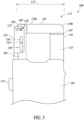
- Fig. 3 depicts the clamp meter 100 of Fig. 2 in the closed position 113.
- the movable jaw 107 bridges from the first leg 105 of the fixed jaw to the second leg 137 of the fixed jaw, and the mating tongue 143 on the second end 119b of the movable jaw 107 mates with a corresponding groove on the first end 141 of the second leg 137.
- the second end 119b of the movable jaw 107 abuts, rests on, or is otherwise held against the first end 141 of the second leg 137.
- the movable jaw 107 is positioned transverse to the first and second legs 105, 137 of the fixed jaw, and closes the electrical measuring loop of the measuring section 115.
- the sliding switch 131 is preferably biased so that, by default, the fixed jaw holds the movable jaw 107 in the closed position 113. In this position, the measuring section 115, including the U-shaped fork 139, is arranged to obtain electrical measurements of an electrical conductor that has been received into the area of the U-shaped fork 139.
- Fig. 4 provides a view of interior components of the clamp meter 100 in the closed position 113.
- An actuator 121 having a sliding switch 131 is configured to move the movable jaw 107 from the closed position 113 to the open position 111, or vice versa.
- the sliding switch 131 is coupled to or integrated with the actuator 121.
- the movable jaw 107 is rotationally coupled to the first leg 105 of the fixed jaw by the rotation pair 110 at the rotational axis 109.
- the actuator 121 is coupled to the cam pair 123 such that motion of the actuator 121 causes motion of the cam pair 123 relative to the rotational axis 109. This arrangement converts linear motion of the actuator 121 to rotational motion of the movable jaw 107.
- the actuator 121 includes a mechanical linkage 125 ( Fig. 3 ) coupled to the cam pair 123 (including pin 127) as described above such that linear motion of the actuator 121 causes rotational motion of the movable jaw 107 about the rotation axis 109.
- the mechanical linkage 125 in this embodiment has a horizontally arranged slot 120 that receives the pin 127 of the cam pair 123.
- the actuator 121 (including the sliding switch 131) may be configured to move in a downward-to-upward motion, or in an upward-to-downward motion. In some embodiments, based upon the configuration of the sliding switch 131, the actuator 121 causes the swinging motion of the movable jaw 107 between the closed and open positions.
- the arrangement of the rotation pair 110 at the rotational axis 109, the cam pair 123, and sliding pair including the guide rib 133 provides a simple yet robust mechanical linkage 125 that converts linear motion of the actuator 121 to rotational motion of the movable jaw 107.
- the clamp meter 100 further comprises a biasing element, such as a coil or spring element 135 housed within the meter body 101.
- the spring element 135 is operably connected to the actuator 121.
- the spring element 135 is housed in the meter body 101 and coupled to the actuator 121. Until motion of the sliding switch 131 causes the actuator 121 to exert a downward compressive force on the spring element 135, the movable jaw 107 remains in the closed position 113. When a downward force is exerted on the sliding switch 131, the actuator 121 moves downward and compresses the spring element 135. This compression of the spring element 135 causes a spring force counterpressure to be exerted that pushes the actuator 121 in an upward direction when the downward force on the sliding switch 131 is released.
- the movable jaw 107 in the closed position 113 bridges the legs of the fixed jaw and together with the fixed jaw forms an electrical measuring loop of the clamp meter 100. More specifically, in the closed position 113, the magnetically conductive core 145 in the U-shaped fork 139 in conjunction with the magnetically conductive material 146 in the movable jaw 107 forms the electrical measuring loop of the clamp meter 100. Furthermore, as shown in Fig. 4 , the mating tongue 143 on the second end 119b of the movable jaw 107 is flush with the corresponding groove on the first end 141 of the second leg 137 of the fixed jaw.
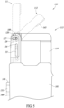
- Fig. 5 depicts the opening and/or closing of the clamp meter 100 for electrical measurement of a conductor received into the measuring section 115 of the clamp meter 100.
- the features of the clamp meter 100 in Fig. 5 are as described in Figs. 2 to 4 above.
- the sliding switch 131 is operably maneuverable in conjunction with the spring element 135.
- the sliding switch 131 is normally held in a static switch position 147 in which the movable jaw 107 is in the closed position 113.
- the sliding switch 131 is pressed in a downward motion toward an actuated switch position 149 causing the movable jaw 107 to be rotated to the open position 111.
- the movable jaw 107 rotates through a transitional position 112 as shown. As long as a downward force on the sliding switch 131 is maintained, the movable jaw 107 remains in the open position 111.
- the sliding switch 131 When the downward force on the sliding switch 131 is released, the upward pressure exerted by the compressed spring element 135 ( Fig. 4 ) causes the sliding switch 131 to move upward, causing the movable jaw 107 to rotate to the closed position 113.
- the sliding switch 131 may be pressed in an upward direction to maneuver the movable jaw 107 between the closed and open positions 113, 111 as described above.
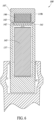
- Fig. 6 depicts a partial cross-sectional side view of the clamp meter 100 in the closed position 113.
- the second leg 137 of the fixed jaw and the movable jaw 107 are shown.
- the second end 119b of the movable jaw 107 comprises a mating tongue 143 and when the movable jaw 107 is in the closed position 113 the mating tongue 143 fits within the groove 142 defined in the first end 141 of the second leg 137 of the fixed jaw.
- This mating tongue 143 and groove 142 aligns the second end 119b of the movable jaw 107 with the first end 141 of the second leg 137, which is important for proper operation of the electrical measurement loop formed by the fixed jaw and the movable jaw in the closed position 113.
- the mating tongue 143 of the movable jaw 107 comprises a narrower width than that of the second leg 137 of the fixed jaw, which enables the mating tongue 143 of the movable jaw 107 to fit within the recessed groove 142 of the first end 141 of the second leg 137.
- the recessed groove 142 may encompass various shapes, dependent on the configuration of the mating tongue 143, to ensure alignment of the movable jaw 107 with the second leg 137 of the fixed jaw.
- the first end 141 of the second leg 137 may be structured with an extrusion or rib that protrudes as a tongue that mates with a corresponding groove defined in the second end 119b of the movable jaw 107. In either case, proper alignment of the second leg 137 with the movable jaw 107 completes the electrical measuring loop and enables the measurement circuitry of the clamp meter to properly and accurately measure electrical characteristics of an electrical conductor being measured.
- Example 1 comprises a clamp meter, comprising: a meter body; and a measuring section that includes: a fixed jaw, wherein the fixed jaw includes a first leg and a second leg extending from the meter body; and a movable jaw that is rotationally coupled to the first leg of the fixed jaw, wherein the fixed jaw in cooperation with the movable jaw forms an electrical measuring loop for measuring an electrical characteristic of an electrical conductor without galvanically contacting the electrical conductor.
- Example 2 may comprise the clamp meter of example 1, or any other example contained herein, wherein the movable jaw is configured to rotate about a rotation axis between a closed position and an open position, and when the movable jaw is in the open position, the measuring section is able to receive the electrical conductor between the first leg and the second leg of the fixed jaw, and when the movable jaw is in the closed position, the movable jaw extends from the first leg to the second leg.
- Example 3 may comprise the clamp meter of example 2, or any other example contained herein, wherein the measuring section has an overall width when the movable jaw is in the closed position, and the overall width of the measuring section is maintained when the movable jaw is rotated to the open position; or wherein the rotation axis is defined at a first end of the movable jaw, and a second end of the movable jaw abuts the second leg of the fixed jaw when the movable jaw is in the closed position.
- Example 4 may comprise the clamp meter of example 2 or 3, or any other example contained herein, wherein the movable jaw is biased towards the closed position.
- Example 5 may comprise the clamp meter of any of examples 1 to 4, or any other example contained herein, wherein the movable jaw is rotationally coupled to the first leg of the fixed jaw at a distal end of the first leg.
- Example 6 may comprise the clamp meter of any of examples 1 to 5, or any other example contained herein, further comprising an actuator configured to move the movable jaw between a closed position and an open position, wherein: the movable jaw is rotationally coupled to the first leg of the fixed jaw by a rotation pair that defines a rotation axis on the movable jaw, and a cam pair couples the movable jaw to the actuator to convert motion of the actuator to rotation of the movable jaw about the rotation axis.
- Example 7 may comprise the clamp meter of example 6, or any other example contained herein, wherein the rotation pair rotationally couples the movable jaw to the first leg of the fixed jaw at a distal end of the first leg, and in the closed position the movable jaw is positioned transverse to the first and second legs of the fixed jaw.
- Example 8 may comprise the clamp meter of example 6 or 7, or any other example contained herein, wherein the cam pair cooperates with the rotation pair to convert linear motion of the actuator to rotation of the movable jaw about the rotation axis.
- Example 9 may comprise the clamp meter of example 8, or any other example contained herein, wherein the cam pair is comprised of a pin that couples the movable jaw to a mechanical linkage of the actuator that urges movement of the pin when the actuator is moved.
- Example 10 may comprise the clamp meter of example 9, or any other example contained herein, wherein the actuator includes a sliding switch, and the pin of the cam pair is positioned within a slot in the mechanical linkage such that linear motion of the sliding switch causes the mechanical linkage to exert a force on the pin that urges the pin to move relative to the rotation pair.
- Example 11 may comprise the clamp meter of any of examples 6 to 10, or any other example contained herein, further comprising a spring element operably connected to the actuator to bias the movable jaw toward the closed position.
- Example 12 may comprise the clamp meter of any of examples 6 to 11, or any other example contained herein, further comprising a slider pair comprised of a pin and corresponding slot that guides linear motion of the actuator with respect to the fixed jaw.
- Example 13 may comprise the clamp meter of any of examples 1 to 12, or any other example contained herein, wherein the first and second legs of the fixed jaw are spaced apart from each other and form a fork that is sized to receive an electrical conductor when the movable jaw is in an open position.
- Example 14 may comprise the clamp meter of example 13, or any other example contained herein, wherein the first and second legs of the fixed jaw form a U-shaped fork.
- Example 15 may comprise the clamp meter of example 13 or 14, or any other example contained herein, wherein a first end of the movable jaw is rotationally coupled to an end of the first leg of the fixed jaw, and when the movable jaw is in a closed position, a second end of the movable jaw is positioned against an end of the second leg of fixed jaw such that the movable jaw bridges the first and second legs of the fixed jaw.
- Example 16 provides a method for electrical measurement using a clamp meter, comprising: actuating a movable jaw of a clamp meter to open a measuring section of the clamp meter, the measuring section including first and second legs of a fixed jaw that extend from a meter body of the clamp meter, wherein actuating the movable jaw includes rotating the movable jaw about a rotation axis on the movable jaw between a closed position and an open position; receiving an electrical conductor into the measuring section when the movable jaw is actuated towards or at the open position; actuating the movable jaw to the closed position in which the movable jaw bridges the first and second legs of the fixed jaw, and together with the fixed jaw, forms a measuring loop around the electrical conductor in the measuring section; and measuring an electrical characteristic of the electrical conductor without galvanically contacting the electrical conductor.
- Example 17 may comprise the method of example 16, or any other example contained herein, further comprising sliding an actuator along a linear path to actuate the movable jaw, wherein the movable jaw is rotationally coupled to the first leg of the fixed jaw by a rotation pair that defines the rotation axis on the movable jaw, and a cam pair is coupled to the movable jaw and the actuator to convert linear motion of the actuator to rotation of the movable jaw.
- Example 18 may comprise the method of example 17, or any other example contained herein, wherein sliding the actuator along the linear path causes a mechanical linkage coupled to the cam pair to convert the linear motion of the actuator to rotation of the movable jaw about the rotation axis, the cam pair including a pin that couples the movable jaw to the mechanical linkage that urges movement of the pin relative to the rotation pair when the actuator is slid along the linear path.
- Example 19 may comprise the method of example 17 or 18, or any other example contained herein, wherein the rotation pair rotationally couples the movable jaw to the first leg of the fixed jaw at a distal end of the first leg, and when the movable jaw is rotated from open position to the closed position, the movable jaw is positioned traverse to the first and second legs of the fixed jaw.
- Example 20 may comprise the method of any of examples 16 to 19, or any other example contained herein, further comprising actuating the movable jaw to the closed position to close the measuring section of the clamp meter, wherein the first and second legs of the fixed jaw are spaced apart from each other and form a fork sized to receive the electrical conductor when the movable jaw is in the open position, and when the movable jaw is actuated to close the measuring section, the movable jaw rotates about the rotation axis to the closed position in which the movable jaw abuts the second leg of the fixed jaw and closes the measuring loop.
Landscapes
- Physics & Mathematics (AREA)
- General Physics & Mathematics (AREA)
- Engineering & Computer Science (AREA)
- Power Engineering (AREA)
- Measuring Leads Or Probes (AREA)
- Measuring Instrument Details And Bridges, And Automatic Balancing Devices (AREA)
Abstract
Description
- The present disclosure relates to a clamp meter having a mechanical linkage for a rotating clamp jaw, and a method for measuring electrical current using the clamp meter.
- Conventional clamp meters are widely used and available in a variety of industrial, commercial, and/or residential settings as an electrical test tool that measures electrical current. Clamp meters are of critical importance for engineers and/or technicians to troubleshoot and resolve electrical issues of operating equipment. Conventional clamp meters are typically comprised of laterally opening rigid jaws that extend from a clamp meter body, and have a rotating trigger positioned on the side of the clamp meter body that can open the jaws. The jaws can clamp around a wire, cable, or other conductor and measure electrical current without having to disconnect or deenergize connected equipment.
- Conventional current transformer clamp meters, for example, may measure alternating current (AC) without having to make direct contact with the conductor. Some variations of clamp meters, such as Hall-effect clamp meters, may measure both alternating current (AC) and direct current (DC) Measurement circuitry coupled to the jaws can detect the magnetic field caused by the flow of current and relay an accurate measurement of the current. Despite the varying types of clamp meters discussed, there remains a need for a clamp meter with rigid jaws that can operate in tight or confined spaces, e.g., where a conductor to be measured has tiny adjacent space for the jaws of the clamp meter to open and fit around the conductor. There also remains a high demand to measure both alternating current (AC) and direct current (DC) of high magnitude with high accuracy in a variety of markets, including the solar energy storage market, in which conductors for conveying high amounts of current may have a form factor with minimal lateral space that precludes the use of a conventional clamp meter to measure current in the conductors.
- Disclosed herein is a clamp meter having a mechanical linkage for a rotating clamp jaw, wherein the mechanical linkage enables the clamp meter to open, fit around a conductor, and close, even when the conductor has limited lateral space to receive the open jaws of the clamp meter.
- Embodiments of the present disclosure include a clamp meter comprising a meter body and a measuring section. The measuring section includes a fixed jaw having a first leg and a second leg that extend from the meter body. The measuring section further includes a movable jaw that is rotationally coupled to the first leg of the fixed jaw. The movable jaw rotates about a rotation axis between a closed position and an open position.
- When the movable jaw is in the open position, the measuring section is able to receive an electrical conductor between the first and second legs of the fixed jaw, after which the movable jaw can be rotated to the closed position for measuring current in the electrical conductor. When the movable jaw is in the closed position, the movable jaw extends from the first leg to the second leg of the fixed jaw, and in cooperation, the fixed jaw and the movable jaw form a measuring loop for measuring an electrical characteristic of the electrical conductor without galvanically contacting the electrical conductor.
- As will be discussed in greater detail herein, embodiments of the clamp meter may include one or more of the following features or aspects in any combination: wherein the measuring section has an overall width when the movable jaw is in the closed position, and the overall width of the measuring section is maintained when the movable jaw is rotated to the open position; wherein the rotation axis is defined at a first end of the movable jaw, and a second end of the movable jaw abuts the second leg of the fixed jaw when the movable jaw is in the closed position; wherein the movable jaw is rotationally coupled to the first leg of the fixed jaw at a distal end of the first leg; and wherein the movable jaw is biased towards the closed position.
- Also as discussed herein, embodiments of the clamp meter may include one or more of the following features or aspects in any combination: the clamp meter further comprising an actuator configured to move the movable jaw between the closed position and the open position, wherein the movable jaw is rotationally coupled to the first leg of the fixed jaw by a rotation pair that defines the rotation axis on the movable jaw and a cam pair that couples the movable jaw to the actuator to convert motion of the actuator to rotation of the movable jaw about the rotation axis; wherein the rotation pair rotationally couples the movable jaw to the first leg of the fixed jaw at a distal end of the first leg, and in the closed position the movable jaw is positioned transverse to the first and second legs of the fixed jaw; wherein the cam pair cooperates with the rotation pair to convert linear motion of the actuator to rotation of the movable jaw about the rotation axis; wherein the cam pair is comprised of a pin that couples the movable jaw to a mechanical linkage of the actuator that urges movement of the pin when the actuator is moved; wherein the actuator includes a sliding switch, and the pin of the cam pair is positioned within a slot in the mechanical linkage such that linear motion of the sliding switch causes the mechanical linkage to exert a force on the pin that urges the pin to move relative to the rotation pair; the clamp meter further comprising a spring element operably connected to the actuator to bias the movable jaw toward the closed position; the clamp meter further comprising a slider pair comprised of a pin and corresponding slot that couples the fixed jaw to the mechanical linkage and guides linear motion of the actuator with respect to the fixed jaw; wherein the first and second legs of the fixed jaw are spaced apart from each other and form a fork that is sized to receive an electrical conductor when the movable jaw is in the open position; wherein the first and second legs of the fixed jaw form a U-shaped fork; and wherein a first end of the movable jaw is rotationally coupled to an end of the first leg of the fixed jaw, and when the movable jaw is in the closed position, a second end of the movable jaw is positioned against an end of the second leg of fixed jaw such that the movable jaw bridges the first and second legs of the fixed jaw.
- The present disclosure also provides methods for electrical measurement using a clamp meter as described herein. For example, a method includes actuating a movable jaw of the clamp meter to open a measuring section of the clamp meter, the measuring section including first and second legs of a fixed jaw that extend from a meter body of the clamp meter, wherein actuating the movable jaw includes rotating the movable jaw about a rotation axis on the movable jaw between a closed position and an open position, and when the movable jaw is actuated to the open position, receiving an electrical conductor into the measuring section. In some cases, the rotation axis is arranged away from the meter body of the clamp meter. When the movable jaw is actuated to the closed position, the movable jaw bridges the first and second legs of the fixed jaw, and in cooperation, the fixed jaw and the movable jaw form an electrical measuring loop around the electrical conductor to measure an electrical characteristic of the electrical conductor without galvanically contacting the electrical conductor.
- Aspects of the present disclosure are best understood from the following detailed description when read with the accompanying figures. It will be understood that these accompanying drawings merely illustrate certain embodiments in accordance with the present application and should not be considered as limitation to the scope of the present application. The aforementioned features and other features of the present application will be fully understood by referring to the accompanying drawings and the appended claims. Unless otherwise specified, accompanying features in these figures are not necessarily drawn to scale.
-
Fig. 1 illustrates a front view of a prior art clamp meter. -
Fig. 2 illustrates a front view of a clamp meter according to the present disclosure, wherein a movable jaw of the clamp meter is shown in an open position. -
Fig. 3 illustrates a front view of the clamp meter inFig. 2 with the movable jaw shown in a closed position. -
Fig. 4 illustrates a back view of the clamp meter inFig. 2 , wherein features inside the clamp meter are shown. -
Fig. 5 illustrates a front view of the clamp meter inFig. 2 , with the movable jaw in process of being actuated from the closed position to the open position, or vice versa. -
Fig. 6 illustrates a partial cross-sectional side view of the clamp meter inFig. 2 with the movable jaw in the closed position. - Electrical test instruments, such as clamp meters, are used to perform daily maintenance and troubleshooting tasks in a variety of industrial settings. Particularly, there is a high demand to measure both AC and DC current of high magnitude with high accuracy, ideally using a clamp meter. For example, in the solar energy market, a technician may wish to measure a three-phase 2000A busbar comprised of three parallel 80mm wide copper bars having 40mm of space between the copper bars. In this particular scenario, a conventional AC/DC clamp meter that has laterally-opening rigid jaws and a rotating side trigger to open the jaws is not able to fit around the copper bars. When opened, the width, geometry, and positioning of the jaws is larger than the gap between the adjacent copper bars. This prevents the jaws from fitting around the copper bars, especially the middle copper bar.
- Additionally, conventional AC/DC clamp meters with rigid jaws that use a rotating side trigger to open the rigid jaws are not easily maneuverable in tight or confined spaces. A flexible Rogowski coil ("R-coil") probe may be used to reach around and surround conductor to be measured. However, R-coil probes can only be used for AC current measurement, which creates an issue when specifically trying to measure high magnitude current of solar energy systems, which primarily consist of DC current. The present disclosure solves these problems by providing a clamp meter with a rigid, movable jaw that can open and allow the clamp meter to fit around a conductor having limited space to the side of the conductor, and close again to measure electrical current in the conductor. Embodiments of the disclosure are illustrated in
Figs. 2-6 and discussed in greater detail below. In one example, a clamp meter includes a mechanical linkage that enables the rotational opening and closing of a movable jaw around a rotation axis. The movable jaw rotates between a closed position and an open position. When the movable jaw is in the open position, the clamp meter can receive an electrical conductor between first and second legs of a fixed jaw. When the movable jaw is in the closed position, the movable jaw extends from the first leg to the second leg of the fixed jaw, and together, the fixed jaw and the movable jaw form an electrical measuring loop for measuring an electrical characteristic of the electrical conductor without galvanically contacting the electrical conductor. With this configuration, the improved clamp meter can operate in environments where a conductor to be measured has limited space around the conductor. - In some cases, the movable jaw is rotationally coupled to the fixed jaw outside of and/or away from the meter body of the clamp meter. When the movable jaw is in the open position, the movable jaw and the first leg of the fixed jaw (to which the movable jaw is rotationally connected) have a width that is sufficiently narrow such that the movable jaw and the first leg of the fixed jaw can fit through the lateral space next to a conductor to be measured. At the same time, the width of the second leg of the fixed jaw is sufficiently narrow such that the second leg of the fixed jaw can fit through the lateral space next to the other side of the conductor to be measured. Once the conductor to be measured has been received into the measurement section between the first and second legs of the fixed jaw, the movable jaw (now positioned behind the conductor) is rotated to the closed position, thereby forming a measuring loop that allows the clamp meter to measure an electrical characteristic of the conductor. In some cases, the clamp meter is able to maintain an overall width of a measuring section of the clamp meter even when the movable jaw is rotated open and closed. In other words, in such cases the overall width of the measuring section does not change or only changes, like 10%, when the movable jaw is rotated open and closed. In the following description, certain specific details are set forth in order to provide a thorough understanding of various disclosed implementations. However, a person skilled in the art will recognize that additional implementations may be practiced without one or more of these specific details, or with other methods, components, materials, etc. Additionally, reference throughout this specification to "one embodiment" or "an embodiment" means that a particular feature, structure, or characteristic described in connection with the embodiment is included in at least one embodiment and may be included in other embodiments as well. Furthermore, appearance of the phrase "in at least one embodiment" in this specification does not necessarily refer to only one embodiment. The particular features, structures, or characteristics of the various embodiments described herein may be combined in any suitable manner in yet additional embodiments. The term "implementation" may be interpreted similar to the term "embodiment" unless otherwise dictated by context.
- For the purposes of the present disclosure, unless otherwise indicated, the phrase "A and B" is nonlimiting and means one or more of (A) and one or more of (B); the phrase "A or B" is nonexclusive and means one or more of (A), one or more of (B), or one or more of (A and B); the phrase "A and/or B" means one or more of (A), one or more of (B), or one or more of (A and B); the phrase "at least one of A and B" and the phrase "one or more of A and B" both mean one or more of (A) and one or more of (B); and the phrase "at least one of A or B" and the phrase "one or more of A or B" both mean one or more of (A), one or more of (B), or one or more of (A and B). In the above, A and B represent any form or type of element, feature, arrangement, component, structure, aspect, action, step, etc.
- An example of a conventional clamp meter known in the prior art is shown in
Fig. 1 . The clamp meter depicted inFig. 1 includes a laterally opening rigid jaw that extends from a clamp meter body, and a trigger positioned on the side of the clamp meter body that, when pressed, operates to rotate the jaw to an open position as shown inFig. 1 . The laterally opening jaw rotates about an axis that is arranged within the meter body. In particular, the device inFig. 1 comprises a hinged jaw clamp positioned opposite to a fixed jaw clamp. The device further comprises a jaw rotational axis that is configured within the clamp meter body. When the trigger is pressed toward the clamp meter body, the hinged jaw clamp rotates about the jaw rotational axis within the clamp meter body from a closed position to an open position. Each of the hinged jaw clamp and the fixed jaw clamp has a hooked portion at their distal end that, when moved to the open position, is wider than the lateral space available to the sides of a conductor to be measured. In such cases, the conventional clamp meter is not able to fit around the conductor to be measured. - Thus, conventional clamp meters as shown in
Fig. 1 are not configured to open and fit around conductors in a limited space. Clamp meters of the type depicted inFig. 1 may be able to fit around wires in some cases but will fail to fit around other conductors in limited-space environments. On the other hand, clamp meters as described herein are suitable for measuring current in conductors in limited-space environments, and accordingly provide numerous benefits as detailed herein. -
Fig. 2 depicts aclamp meter 100 embodying principles of the present disclosure. Theclamp meter 100 can fit around a conductor having limited space to the side of the conductor. Theclamp meter 100 includes ameter body 101, wherein themeter body 101 encapsulates components of theclamp meter 100 that are used for measuring electrical characteristics as known in the art. For example, themeter body 101 may be configured with a variety of conventional electrical measurement circuitry. The electrical measurement circuitry is not shown for simplicity of the drawings. - The
clamp meter 100 further includes a measuring section having a fixed jaw and a movable jaw. While the fixed jaw is typically (though not necessarily) an integral single-piece element, e.g., having a single integral magneticallyconductive core 145 as shown inFig. 4 , for purposes of description herein, the fixed jaw is considered as having afirst leg 105 extending from themeter body 101 and asecond leg 137 extending from themeter body 101. The first andsecond legs movable jaw 107, may be coated with plastic moldings and may be composed of ferrite iron or other similar magnetically conductive core materials. InFig. 2 , thefirst leg 105 of the fixed jaw extends upward from a side of themeter body 101 and includes aproximal end 117a and adistal end 117b located opposite to theproximal end 117a, away from themeter body 101. Thesecond leg 137 of the fixed jaw also extends upward from a side of themeter body 101. Thesecond leg 137 of the fixed jaw is spaced apart from thefirst leg 105 and may extend from themeter body 101 parallel to thefirst leg 105. - The first and
second legs Fig. 2 as extending from themeter body 101 parallel to each other, but alternatively they may be positioned relative to themeter body 101 in other configurations as needed. Thesecond leg 137 of the fixed jaw includes afirst end 141 positioned away from themeter body 101. Thefirst end 141 is structured to receive asecond end 119b of themovable jaw 107, as discussed in further detail below, when themovable jaw 107 is in the closed position. - The
movable jaw 107 includes arotation axis 109 that rotatably couples themovable jaw 107 to thefirst leg 105 of fixed jaw. Therotation axis 109 inFig. 2 is advantageously coupled to thefirst leg 105 at thedistal end 117b of thefirst leg 105, away from themeter body 101, as opposed to within or on themeter body 101. Therotation axis 109 enables themovable jaw 107 to rotate about therotation axis 109 from aclosed position 113 as shown inFig. 3 to anopen position 111 as shown inFig. 2 . While in theopen position 111, themovable jaw 107 has an upright stance approximately in line with thefirst leg 105 of the fixed jaw. Coupling therotation axis 109 of themovable jaw 107 to thefirst leg 105 of the fixed jaw, away from themeter body 101, results in a configuration that reduces the amount of space required to fit theclamp meter 100 around an electrical conductor to obtain electrical measurements using theclamp meter 100. As described below, thefirst leg 105 of the fixed jaw has an aperture through which a pin of themovable jaw 107 extends. Together the aperture and pin form arotation pair 110 that provides therotation axis 109 about which themovable jaw 107 rotates. - The
clamp meter 100 further includes an actuator, which as illustrated may include a slidingswitch 131. The slidingswitch 131 is slidably mounted on thefirst leg 105 of the fixed jaw. In various embodiments, the slidingswitch 131 may be positioned on the left side, right side, front, or bottom of themeter body 101. The slidingswitch 131 may be configured and/or located in a manner that is convenient for the user. As will be understood from the description below, themovable jaw 107 and the actuator (sliding switch) 131 include components that together form acam pair 123. Thecam pair 123 couples themovable jaw 107 and the slidingswitch 131 in such a manner as to convert motion of the slidingswitch 131 to rotation of themovable jaw 107 about therotation axis 109. - The
clamp meter 100 further includes aslider pair 130 comprising components of thefirst leg 105 of the fixed jaw and the slidingswitch 131. The slidingswitch 131 may move linearly as guided by aguide rib 133 sliding in a vertically orientedchannel 134, as shown. Theguide rib 133, which may be defined on thefirst leg 105, guides the slidingswitch 131 to move linearly in a downward or an upward motion, dependent on the operation and configuration of the slidingswitch 131. InFigs. 2 and3 , theguide rib 133 is arranged within thechannel 134 defined in amechanical linkage 125 that is coupled to or integrated with the slidingswitch 131. Thechannel 134 is interposed between theproximal end 117a and thedistal end 117b of thefirst leg 105 of the fixed jaw. However, in alternative embodiments, theguide rib 133 may be positioned in other locations of theclamp meter 100 to achieve the desired operation of guiding the linear motion of the slidingswitch 131 along a linear path. - The
movable jaw 107 comprises apin 127 that is positioned within aslot 120. Thepin 127 may extend through a groove or slot 129 defined in thedistal end 117b of thefirst leg 105 of the fixed jaw. Thepin 127 may be formed of any suitable structure that enables thepin 127 to move relative to therotational axis 109 when urged by movement of the slidingswitch 131. This combination of thepin 127 and the slot 120 (comprising the cam pair 123), when actuated by movement of the slidingswitch 131, provides a simple yet robust mechanism for causing themovable jaw 107 to swing or rotate from theclosed position 113 to theopen position 111, and vice versa. While theslot 129, if used, is illustrated as being arc-shaped, theslot 129 may also encompass varying structures or shapes that help prevent the fixed jaw from interfering with the movement of thepin 127 as described above. - The size of the
movable jaw 107 and other components of theclamp meter 100 may vary and may not be to scale as shown in the figures. For example, the size of themovable jaw 107 may be narrower, in some cases depending on the construction of the first andsecond legs movable jaw 107 may also be determined by the intended electrical measurement requirements of theclamp meter 100. Preferably themovable jaw 107 and the first andsecond legs clamp meter 100 too heavy to carry and maneuver as needed. Thus, the size of the first andsecond legs movable jaw 107 may be determined according to the anticipated use of theclamp meter 100. - The
movable jaw 107 has afirst end 119a and an opposingsecond end 119b. In at least one implementation, themovable jaw 107 further comprises amating tongue 143 positioned on thesecond end 119b of themovable jaw 107. Themating tongue 143 is shaped to fit with acorresponding groove 142 on thefirst end 141 of thesecond leg 137. When theclamp meter 100 is in theopen position 111, themovable jaw 107 is aligned with thefirst leg 105 of the fixed jaw. When themovable jaw 107 is aligned with thefirst leg 105, themovable jaw 107 and thefirst leg 105 have a width that fits within the lateral space to one side of the conductor to be measured, while thesecond leg 137 of the fixed jaw has a width that fits within the lateral space to the other side of the conductor to be measured. Accordingly, theclamp meter 100 can open and maneuver around a conductor having limited space on either side of the conductor, then close around the conductor for measuring electrical characteristics (e.g., current) flowing in the conductor without galvanically contacting the conductor. - When the
clamp meter 100 is in theclosed position 113, themovable jaw 107 is transverse to thefirst leg 105 and themating tongue 143 of themovable jaw 107 fits within thegroove 142 in thefirst end 141 of thesecond leg 137. Together, the fixed jaw (including the first andsecond legs 105, 137) and themovable jaw 107 create ameasuring section 115 with respect to themeter body 101 for measuring electrical characteristics of a conductor received into the measuringsection 115. The measuringsection 115 includes the area between the first andsecond legs section 115 is bounded by an upper end of themeter body 101 and by themovable jaw 107 when themovable jaw 107 is in the closed position 113 (as shown inFig. 3 ). The measuringsection 115 contains the area where an electrical conductor to be measured is positioned. In the implementation shown inFigs. 2 to 4 , the fixed jaw (including first andsecond legs 105, 137) forms afork 139 that can receive an electrical conductor to be measured. In the illustrated embodiment, the fixed jaw forms aU-shaped fork 139, e.g., as best seen inFigs. 4 and5 . - When the
movable jaw 107 is in the closed position 113 (as shown inFig. 3 ), theU-shaped fork 139 has an overall width that is maintained whether theclamp meter 100 is in the closed position 113 (as shown inFig. 3 ) or in the open position 111 (as shown inFig. 2 ). In other words, when themovable jaw 107 swings open to allow theU-shaped fork 139 to receive an electrical conductor, the overall width of the U-shaped fork does not substantially change. - By rotatably coupling the
movable jaw 107 to thefirst leg 105 of the fixed jaw at thedistal end 117b of thefirst leg 105, with the fixed jaw arranged as having theU-shaped fork 139 as shown, theclamp meter 100 is allowed to open and access electrical conductors having narrow lateral space to accurately measure current in the electrical conductors. Theclamp meter 100 is capable of opening and maneuvering around a conductor (not shown) having limited spaced on either side of the conductor. Theclamp meter 100 can then close around the conductor for electrical measurement of current flowing in the conductor without galvanically contacting the conductor. -
Fig. 3 depicts theclamp meter 100 ofFig. 2 in theclosed position 113. - In the
closed position 113, themovable jaw 107 bridges from thefirst leg 105 of the fixed jaw to thesecond leg 137 of the fixed jaw, and themating tongue 143 on thesecond end 119b of themovable jaw 107 mates with a corresponding groove on thefirst end 141 of thesecond leg 137. Thesecond end 119b of themovable jaw 107 abuts, rests on, or is otherwise held against thefirst end 141 of thesecond leg 137. Themovable jaw 107 is positioned transverse to the first andsecond legs section 115. - The sliding
switch 131 is preferably biased so that, by default, the fixed jaw holds themovable jaw 107 in theclosed position 113. In this position, the measuringsection 115, including theU-shaped fork 139, is arranged to obtain electrical measurements of an electrical conductor that has been received into the area of theU-shaped fork 139. -
Fig. 4 provides a view of interior components of theclamp meter 100 in theclosed position 113. Anactuator 121 having a slidingswitch 131 is configured to move themovable jaw 107 from theclosed position 113 to theopen position 111, or vice versa. The slidingswitch 131 is coupled to or integrated with theactuator 121. As depicted inFig. 2 , themovable jaw 107 is rotationally coupled to thefirst leg 105 of the fixed jaw by therotation pair 110 at therotational axis 109. Theactuator 121 is coupled to thecam pair 123 such that motion of theactuator 121 causes motion of thecam pair 123 relative to therotational axis 109. This arrangement converts linear motion of theactuator 121 to rotational motion of themovable jaw 107. - The
actuator 121 includes a mechanical linkage 125 (Fig. 3 ) coupled to the cam pair 123 (including pin 127) as described above such that linear motion of theactuator 121 causes rotational motion of themovable jaw 107 about therotation axis 109. Themechanical linkage 125 in this embodiment has a horizontally arrangedslot 120 that receives thepin 127 of thecam pair 123. When a linear force is applied to the slidingswitch 131, causing the slidingswitch 131 to move in a downward direction, themechanical linkage 125 connected to the slidingswitch 131 pulls on thepin 127 and urges thepin 127 to move downward as shown inFig. 5 , causing themovable jaw 107 to rotate about therotational axis 109 from the closed position to the open position. The actuator 121 (including the sliding switch 131) may be configured to move in a downward-to-upward motion, or in an upward-to-downward motion. In some embodiments, based upon the configuration of the slidingswitch 131, theactuator 121 causes the swinging motion of themovable jaw 107 between the closed and open positions. The arrangement of therotation pair 110 at therotational axis 109, thecam pair 123, and sliding pair including theguide rib 133, provides a simple yet robustmechanical linkage 125 that converts linear motion of theactuator 121 to rotational motion of themovable jaw 107. - The
clamp meter 100 further comprises a biasing element, such as a coil orspring element 135 housed within themeter body 101. In at least one embodiment, thespring element 135 is operably connected to theactuator 121. For example, in one embodiment, thespring element 135 is housed in themeter body 101 and coupled to theactuator 121. Until motion of the slidingswitch 131 causes theactuator 121 to exert a downward compressive force on thespring element 135, themovable jaw 107 remains in theclosed position 113. When a downward force is exerted on the slidingswitch 131, theactuator 121 moves downward and compresses thespring element 135. This compression of thespring element 135 causes a spring force counterpressure to be exerted that pushes theactuator 121 in an upward direction when the downward force on the slidingswitch 131 is released. - As described above, the
movable jaw 107 in theclosed position 113 bridges the legs of the fixed jaw and together with the fixed jaw forms an electrical measuring loop of theclamp meter 100. More specifically, in theclosed position 113, the magneticallyconductive core 145 in theU-shaped fork 139 in conjunction with the magneticallyconductive material 146 in themovable jaw 107 forms the electrical measuring loop of theclamp meter 100. Furthermore, as shown inFig. 4 , themating tongue 143 on thesecond end 119b of themovable jaw 107 is flush with the corresponding groove on thefirst end 141 of thesecond leg 137 of the fixed jaw. -
Fig. 5 depicts the opening and/or closing of theclamp meter 100 for electrical measurement of a conductor received into the measuringsection 115 of theclamp meter 100. The features of theclamp meter 100 inFig. 5 are as described inFigs. 2 to 4 above. - In at least one embodiment, the sliding
switch 131 is operably maneuverable in conjunction with thespring element 135. The slidingswitch 131 is normally held in astatic switch position 147 in which themovable jaw 107 is in theclosed position 113. To operate theclamp meter 100, the slidingswitch 131 is pressed in a downward motion toward an actuatedswitch position 149 causing themovable jaw 107 to be rotated to theopen position 111. When the slidingswitch 131 transitions between thestatic switch position 147 and the actuatedswitch position 149, themovable jaw 107 rotates through atransitional position 112 as shown. As long as a downward force on the slidingswitch 131 is maintained, themovable jaw 107 remains in theopen position 111. When the downward force on the slidingswitch 131 is released, the upward pressure exerted by the compressed spring element 135 (Fig. 4 ) causes the slidingswitch 131 to move upward, causing themovable jaw 107 to rotate to theclosed position 113. In other embodiments, the slidingswitch 131 may be pressed in an upward direction to maneuver themovable jaw 107 between the closed andopen positions -
Fig. 6 depicts a partial cross-sectional side view of theclamp meter 100 in theclosed position 113. For purposes of illustration, only thesecond leg 137 of the fixed jaw and themovable jaw 107 are shown. As mentioned above, thesecond end 119b of themovable jaw 107 comprises amating tongue 143 and when themovable jaw 107 is in theclosed position 113 themating tongue 143 fits within thegroove 142 defined in thefirst end 141 of thesecond leg 137 of the fixed jaw. Thismating tongue 143 and groove 142 aligns thesecond end 119b of themovable jaw 107 with thefirst end 141 of thesecond leg 137, which is important for proper operation of the electrical measurement loop formed by the fixed jaw and the movable jaw in theclosed position 113. - As shown in
Fig. 6 , themating tongue 143 of themovable jaw 107 comprises a narrower width than that of thesecond leg 137 of the fixed jaw, which enables themating tongue 143 of themovable jaw 107 to fit within the recessedgroove 142 of thefirst end 141 of thesecond leg 137. The recessedgroove 142 may encompass various shapes, dependent on the configuration of themating tongue 143, to ensure alignment of themovable jaw 107 with thesecond leg 137 of the fixed jaw. In some embodiments, thefirst end 141 of thesecond leg 137 may be structured with an extrusion or rib that protrudes as a tongue that mates with a corresponding groove defined in thesecond end 119b of themovable jaw 107. In either case, proper alignment of thesecond leg 137 with themovable jaw 107 completes the electrical measuring loop and enables the measurement circuitry of the clamp meter to properly and accurately measure electrical characteristics of an electrical conductor being measured. - The following section of the description relates to further examples. The examples in this section are not claims. The claims are set forth below in the later section headed "claims".
- Example 1 comprises a clamp meter, comprising: a meter body; and a measuring section that includes: a fixed jaw, wherein the fixed jaw includes a first leg and a second leg extending from the meter body; and a movable jaw that is rotationally coupled to the first leg of the fixed jaw, wherein the fixed jaw in cooperation with the movable jaw forms an electrical measuring loop for measuring an electrical characteristic of an electrical conductor without galvanically contacting the electrical conductor.
- Example 2 may comprise the clamp meter of example 1, or any other example contained herein, wherein the movable jaw is configured to rotate about a rotation axis between a closed position and an open position, and when the movable jaw is in the open position, the measuring section is able to receive the electrical conductor between the first leg and the second leg of the fixed jaw, and when the movable jaw is in the closed position, the movable jaw extends from the first leg to the second leg.
- Example 3 may comprise the clamp meter of example 2, or any other example contained herein, wherein the measuring section has an overall width when the movable jaw is in the closed position, and the overall width of the measuring section is maintained when the movable jaw is rotated to the open position; or wherein the rotation axis is defined at a first end of the movable jaw, and a second end of the movable jaw abuts the second leg of the fixed jaw when the movable jaw is in the closed position.
- Example 4 may comprise the clamp meter of example 2 or 3, or any other example contained herein, wherein the movable jaw is biased towards the closed position.
- Example 5 may comprise the clamp meter of any of examples 1 to 4, or any other example contained herein, wherein the movable jaw is rotationally coupled to the first leg of the fixed jaw at a distal end of the first leg.
- Example 6 may comprise the clamp meter of any of examples 1 to 5, or any other example contained herein, further comprising an actuator configured to move the movable jaw between a closed position and an open position, wherein: the movable jaw is rotationally coupled to the first leg of the fixed jaw by a rotation pair that defines a rotation axis on the movable jaw, and a cam pair couples the movable jaw to the actuator to convert motion of the actuator to rotation of the movable jaw about the rotation axis.
- Example 7 may comprise the clamp meter of example 6, or any other example contained herein, wherein the rotation pair rotationally couples the movable jaw to the first leg of the fixed jaw at a distal end of the first leg, and in the closed position the movable jaw is positioned transverse to the first and second legs of the fixed jaw.
- Example 8 may comprise the clamp meter of example 6 or 7, or any other example contained herein, wherein the cam pair cooperates with the rotation pair to convert linear motion of the actuator to rotation of the movable jaw about the rotation axis.
- Example 9 may comprise the clamp meter of example 8, or any other example contained herein, wherein the cam pair is comprised of a pin that couples the movable jaw to a mechanical linkage of the actuator that urges movement of the pin when the actuator is moved.
- Example 10 may comprise the clamp meter of example 9, or any other example contained herein, wherein the actuator includes a sliding switch, and the pin of the cam pair is positioned within a slot in the mechanical linkage such that linear motion of the sliding switch causes the mechanical linkage to exert a force on the pin that urges the pin to move relative to the rotation pair.
- Example 11 may comprise the clamp meter of any of examples 6 to 10, or any other example contained herein, further comprising a spring element operably connected to the actuator to bias the movable jaw toward the closed position.
- Example 12 may comprise the clamp meter of any of examples 6 to 11, or any other example contained herein, further comprising a slider pair comprised of a pin and corresponding slot that guides linear motion of the actuator with respect to the fixed jaw.
- Example 13 may comprise the clamp meter of any of examples 1 to 12, or any other example contained herein, wherein the first and second legs of the fixed jaw are spaced apart from each other and form a fork that is sized to receive an electrical conductor when the movable jaw is in an open position.
- Example 14 may comprise the clamp meter of example 13, or any other example contained herein, wherein the first and second legs of the fixed jaw form a U-shaped fork.
- Example 15 may comprise the clamp meter of example 13 or 14, or any other example contained herein, wherein a first end of the movable jaw is rotationally coupled to an end of the first leg of the fixed jaw, and when the movable jaw is in a closed position, a second end of the movable jaw is positioned against an end of the second leg of fixed jaw such that the movable jaw bridges the first and second legs of the fixed jaw.
- Example 16 provides a method for electrical measurement using a clamp meter, comprising: actuating a movable jaw of a clamp meter to open a measuring section of the clamp meter, the measuring section including first and second legs of a fixed jaw that extend from a meter body of the clamp meter, wherein actuating the movable jaw includes rotating the movable jaw about a rotation axis on the movable jaw between a closed position and an open position; receiving an electrical conductor into the measuring section when the movable jaw is actuated towards or at the open position; actuating the movable jaw to the closed position in which the movable jaw bridges the first and second legs of the fixed jaw, and together with the fixed jaw, forms a measuring loop around the electrical conductor in the measuring section; and measuring an electrical characteristic of the electrical conductor without galvanically contacting the electrical conductor.
- Example 17 may comprise the method of example 16, or any other example contained herein, further comprising sliding an actuator along a linear path to actuate the movable jaw, wherein the movable jaw is rotationally coupled to the first leg of the fixed jaw by a rotation pair that defines the rotation axis on the movable jaw, and a cam pair is coupled to the movable jaw and the actuator to convert linear motion of the actuator to rotation of the movable jaw.
- Example 18 may comprise the method of example 17, or any other example contained herein, wherein sliding the actuator along the linear path causes a mechanical linkage coupled to the cam pair to convert the linear motion of the actuator to rotation of the movable jaw about the rotation axis, the cam pair including a pin that couples the movable jaw to the mechanical linkage that urges movement of the pin relative to the rotation pair when the actuator is slid along the linear path.
- Example 19 may comprise the method of example 17 or 18, or any other example contained herein, wherein the rotation pair rotationally couples the movable jaw to the first leg of the fixed jaw at a distal end of the first leg, and when the movable jaw is rotated from open position to the closed position, the movable jaw is positioned traverse to the first and second legs of the fixed jaw.
- Example 20 may comprise the method of any of examples 16 to 19, or any other example contained herein, further comprising actuating the movable jaw to the closed position to close the measuring section of the clamp meter, wherein the first and second legs of the fixed jaw are spaced apart from each other and form a fork sized to receive the electrical conductor when the movable jaw is in the open position, and when the movable jaw is actuated to close the measuring section, the movable jaw rotates about the rotation axis to the closed position in which the movable jaw abuts the second leg of the fixed jaw and closes the measuring loop.
- The various example embodiments described above can be combined to provide further embodiments. These and other changes can be made to the embodiments considering the above-detailed description. In general, in the following claims, the terms used should not be construed to limit the claims to the specific embodiments disclosed in the specification and the claims but should be construed to include all possible embodiments along with the full scope of equivalents to which such claims are entitled. Accordingly, the claims are not limited by the disclosure.
Claims (15)
- A clamp meter, comprising:a meter body; anda measuring section that includes:a fixed jaw, wherein the fixed jaw includes a first leg and a second leg extending from the meter body; anda movable jaw that is rotationally coupled to the first leg of the fixed jaw, wherein the fixed jaw in cooperation with the movable jaw forms an electrical measuring loop for measuring an electrical characteristic of an electrical conductor without galvanically contacting the electrical conductor.
- The clamp meter of claim 1, wherein the movable jaw is configured to rotate about a rotation axis between a closed position and an open position, and when the movable jaw is in the open position, the measuring section is able to receive the electrical conductor between the first leg and the second leg of the fixed jaw, and when the movable jaw is in the closed position, the movable jaw extends from the first leg to the second leg.
- The clamp meter of claim 2, wherein the measuring section has an overall width when the movable jaw is in the closed position, and the overall width of the measuring section is maintained when the movable jaw is rotated to the open position; or wherein the rotation axis is defined at a first end of the movable jaw, and a second end of the movable jaw abuts the second leg of the fixed jaw when the movable jaw is in the closed position; and/or
wherein the movable jaw is biased towards the closed position. - The clamp meter of any of claims 1 to 3, wherein the movable jaw is rotationally coupled to the first leg of the fixed jaw at a distal end of the first leg.
- The clamp meter of any of claims 1 to 4, further comprising an actuator configured to move the movable jaw between a closed position and an open position, wherein:the movable jaw is rotationally coupled to the first leg of the fixed jaw by a rotation pair that defines a rotation axis on the movable jaw, anda cam pair couples the movable jaw to the actuator to convert motion of the actuator to rotation of the movable jaw about the rotation axis; optionally wherein the rotation pair rotationally couples the movable jaw to the first leg of the fixed jaw at a distal end of the first leg, and in the closed position the movable jaw is positioned transverse to the first and second legs of the fixed jaw.
- The clamp meter of claim 5, wherein the cam pair cooperates with the rotation pair to convert linear motion of the actuator to rotation of the movable jaw about the rotation axis; optionally wherein the cam pair is comprised of a pin that couples the movable jaw to a mechanical linkage of the actuator that urges movement of the pin when the actuator is moved; further optionally wherein the actuator includes a sliding switch, and the pin of the cam pair is positioned within a slot in the mechanical linkage such that linear motion of the sliding switch causes the mechanical linkage to exert a force on the pin that urges the pin to move relative to the rotation pair.
- The clamp meter of claim 5, further comprising a spring element operably connected to the actuator to bias the movable jaw toward the closed position; and/or
further comprising a slider pair comprised of a pin and corresponding slot that guides linear motion of the actuator with respect to the fixed jaw. - The clamp meter of any of claims 1 to 7, wherein the first and second legs of the fixed jaw are spaced apart from each other and form a fork that is sized to receive an electrical conductor when the movable jaw is in an open position.
- The clamp meter of claim 8, wherein the first and second legs of the fixed jaw form a U-shaped fork.
- The clamp meter of claim 8 or 9, wherein a first end of the movable jaw is rotationally coupled to an end of the first leg of the fixed jaw, and when the movable jaw is in a closed position, a second end of the movable jaw is positioned against an end of the second leg of fixed jaw such that the movable jaw bridges the first and second legs of the fixed jaw.
- A method for electrical measurement using a clamp meter, comprising:actuating a movable jaw of a clamp meter to open a measuring section of the clamp meter, the measuring section including first and second legs of a fixed jaw that extend from a meter body of the clamp meter, wherein actuating the movable jaw includes rotating the movable jaw about a rotation axis on the movable jaw between a closed position and an open position;receiving an electrical conductor into the measuring section when the movable jaw is actuated towards or at the open position;actuating the movable jaw to the closed position in which the movable jaw bridges the first and second legs of the fixed jaw, and together with the fixed jaw, forms a measuring loop around the electrical conductor in the measuring section; andmeasuring an electrical characteristic of the electrical conductor without galvanically contacting the electrical conductor.
- The method of claim 11, further comprising sliding an actuator along a linear path to actuate the movable jaw,
wherein the movable jaw is rotationally coupled to the first leg of the fixed jaw by a rotation pair that defines the rotation axis on the movable jaw, and a cam pair is coupled to the movable jaw and the actuator to convert linear motion of the actuator to rotation of the movable jaw. - The method of claim 12, wherein sliding the actuator along the linear path causes a mechanical linkage coupled to the cam pair to convert the linear motion of the actuator to rotation of the movable jaw about the rotation axis, the cam pair including a pin that couples the movable jaw to the mechanical linkage that urges movement of the pin relative to the rotation pair when the actuator is slid along the linear path.
- The method of claim 12 or 13, wherein the rotation pair rotationally couples the movable jaw to the first leg of the fixed jaw at a distal end of the first leg, and when the movable jaw is rotated from open position to the closed position, the movable jaw is positioned traverse to the first and second legs of the fixed jaw.
- The method of any of claims 16 to 14, further comprising actuating the movable jaw to the closed position to close the measuring section of the clamp meter,wherein the first and second legs of the fixed jaw are spaced apart from each other and form a fork sized to receive the electrical conductor when the movable jaw is in the open position, andwhen the movable jaw is actuated to close the measuring section, the movable jaw rotates about the rotation axis to the closed position in which the movable jaw abuts the second leg of the fixed jaw and closes the measuring loop.
Applications Claiming Priority (1)
| Application Number | Priority Date | Filing Date | Title |
|---|---|---|---|
| CN202311579654.XA CN120064720A (en) | 2023-11-23 | 2023-11-23 | Jawset capable of realizing opening and closing of jaw through mechanical link mechanism |
Publications (1)
| Publication Number | Publication Date |
|---|---|
| EP4560325A1 true EP4560325A1 (en) | 2025-05-28 |
Family
ID=91469974
Family Applications (1)
| Application Number | Title | Priority Date | Filing Date |
|---|---|---|---|
| EP24181167.8A Pending EP4560325A1 (en) | 2023-11-23 | 2024-06-10 | Clamp meter with rotating clamp jaw |
Country Status (3)
| Country | Link |
|---|---|
| US (1) | US20250172591A1 (en) |
| EP (1) | EP4560325A1 (en) |
| CN (1) | CN120064720A (en) |
Citations (6)
| Publication number | Priority date | Publication date | Assignee | Title |
|---|---|---|---|---|
| US4258348A (en) * | 1979-11-13 | 1981-03-24 | Stb Transformer Company | Current measuring transformer |
| FR2673727A1 (en) * | 1991-03-04 | 1992-09-11 | Marechaux Dubost Instr | Clip-on ammeter with improved actuating device |
| DE19962323A1 (en) * | 1999-12-23 | 2001-07-19 | Metrawatt Gmbh Gossen | Electrical measurement device, e.g. current tong tester; has annular jaw head with at least one moving jaw element, where width with jaw element open is not greater than with jaw element closed |
| CN202562992U (en) * | 2012-04-22 | 2012-11-28 | 杨东明 | Clip on ammeter |
| EP3121606A1 (en) * | 2014-03-20 | 2017-01-25 | Osaka City University | Clamp-type ammeter |
| CN216771823U (en) * | 2021-12-21 | 2022-06-17 | 浙江皓博计量校准有限公司 | Novel clamp-on ammeter |
Family Cites Families (1)
| Publication number | Priority date | Publication date | Assignee | Title |
|---|---|---|---|---|
| US6975104B2 (en) * | 2004-02-20 | 2005-12-13 | Ideal Industries, Inc. | Clamp meter with dual display |
-
2023
- 2023-11-23 CN CN202311579654.XA patent/CN120064720A/en active Pending
-
2024
- 2024-05-09 US US18/659,907 patent/US20250172591A1/en active Pending
- 2024-06-10 EP EP24181167.8A patent/EP4560325A1/en active Pending
Patent Citations (6)
| Publication number | Priority date | Publication date | Assignee | Title |
|---|---|---|---|---|
| US4258348A (en) * | 1979-11-13 | 1981-03-24 | Stb Transformer Company | Current measuring transformer |
| FR2673727A1 (en) * | 1991-03-04 | 1992-09-11 | Marechaux Dubost Instr | Clip-on ammeter with improved actuating device |
| DE19962323A1 (en) * | 1999-12-23 | 2001-07-19 | Metrawatt Gmbh Gossen | Electrical measurement device, e.g. current tong tester; has annular jaw head with at least one moving jaw element, where width with jaw element open is not greater than with jaw element closed |
| CN202562992U (en) * | 2012-04-22 | 2012-11-28 | 杨东明 | Clip on ammeter |
| EP3121606A1 (en) * | 2014-03-20 | 2017-01-25 | Osaka City University | Clamp-type ammeter |
| CN216771823U (en) * | 2021-12-21 | 2022-06-17 | 浙江皓博计量校准有限公司 | Novel clamp-on ammeter |
Also Published As
| Publication number | Publication date |
|---|---|
| CN120064720A (en) | 2025-05-30 |
| US20250172591A1 (en) | 2025-05-29 |
Similar Documents
| Publication | Publication Date | Title |
|---|---|---|
| US20010052765A1 (en) | Non-contact type current measuring instrument | |
| US4825154A (en) | Current probe | |
| US6456060B1 (en) | Multi-meter with locking clamp | |
| US9400289B2 (en) | Clamp sensor and measurement apparatus | |
| KR101544953B1 (en) | Current transformer | |
| CN106814255A (en) | A kind of SF6 breakers dynamic contact resistance detection means | |
| CN108508254B (en) | Current measuring device with additional extension operation handle | |
| US20250172591A1 (en) | Clamp meter with rotating clamp jaw | |
| US9791479B2 (en) | Slide closure current tester | |
| CN119510846A (en) | A kind of open and close current transformer | |
| CN209945703U (en) | Circuit breaker contact spring measuring device | |
| US20200203878A1 (en) | Disconnect terminal | |
| Palani et al. | Real-time techniques to measure winding displacement in transformers during short-circuit tests | |
| JP2014142284A (en) | Clamp type ampere meter | |
| CN105807098A (en) | Detector for a conductor of an electrical network | |
| CN101390180A (en) | Magnetostrictive electrical switching devices | |
| JP2008102035A (en) | Clamp tester | |
| CN118795179B (en) | An adjustable split current detection probe | |
| CN103712537B (en) | Measurement apparatus for high-voltage switch cabinet mechanical stroke | |
| CN220913301U (en) | Relay contact detection device | |
| CN202471801U (en) | Current monitor | |
| CN117849409A (en) | A circular telegram equipment detection case for assembling electric wire | |
| CN220171137U (en) | Clamp structure of clamp ammeter | |
| GB2291273A (en) | Electrical test probe | |
| CN103197116A (en) | Sensor for measuring a current in an electric cable |
Legal Events
| Date | Code | Title | Description |
|---|---|---|---|
| PUAI | Public reference made under article 153(3) epc to a published international application that has entered the european phase |
Free format text: ORIGINAL CODE: 0009012 |
|
| STAA | Information on the status of an ep patent application or granted ep patent |
Free format text: STATUS: THE APPLICATION HAS BEEN PUBLISHED |
|
| AK | Designated contracting states |
Kind code of ref document: A1 Designated state(s): AL AT BE BG CH CY CZ DE DK EE ES FI FR GB GR HR HU IE IS IT LI LT LU LV MC ME MK MT NL NO PL PT RO RS SE SI SK SM TR |
|
| STAA | Information on the status of an ep patent application or granted ep patent |
Free format text: STATUS: REQUEST FOR EXAMINATION WAS MADE |
|
| STAA | Information on the status of an ep patent application or granted ep patent |
Free format text: STATUS: EXAMINATION IS IN PROGRESS |
|
| 17P | Request for examination filed |
Effective date: 20251128 |
|
| 17Q | First examination report despatched |
Effective date: 20251212 |