EP4560215A1 - Control device, control method, and air conditioner - Google Patents
Control device, control method, and air conditioner Download PDFInfo
- Publication number
- EP4560215A1 EP4560215A1 EP23857317.4A EP23857317A EP4560215A1 EP 4560215 A1 EP4560215 A1 EP 4560215A1 EP 23857317 A EP23857317 A EP 23857317A EP 4560215 A1 EP4560215 A1 EP 4560215A1
- Authority
- EP
- European Patent Office
- Prior art keywords
- time
- temperature
- control device
- deviation
- set value
- Prior art date
- Legal status (The legal status is an assumption and is not a legal conclusion. Google has not performed a legal analysis and makes no representation as to the accuracy of the status listed.)
- Pending
Links
Images



Classifications
-
- F—MECHANICAL ENGINEERING; LIGHTING; HEATING; WEAPONS; BLASTING
- F24—HEATING; RANGES; VENTILATING
- F24F—AIR-CONDITIONING; AIR-HUMIDIFICATION; VENTILATION; USE OF AIR CURRENTS FOR SCREENING
- F24F11/00—Control or safety arrangements
- F24F11/70—Control systems characterised by their outputs; Constructional details thereof
- F24F11/80—Control systems characterised by their outputs; Constructional details thereof for controlling the temperature of the supplied air
- F24F11/86—Control systems characterised by their outputs; Constructional details thereof for controlling the temperature of the supplied air by controlling compressors within refrigeration or heat pump circuits
-
- F—MECHANICAL ENGINEERING; LIGHTING; HEATING; WEAPONS; BLASTING
- F24—HEATING; RANGES; VENTILATING
- F24F—AIR-CONDITIONING; AIR-HUMIDIFICATION; VENTILATION; USE OF AIR CURRENTS FOR SCREENING
- F24F11/00—Control or safety arrangements
- F24F11/50—Control or safety arrangements characterised by user interfaces or communication
- F24F11/61—Control or safety arrangements characterised by user interfaces or communication using timers
-
- F—MECHANICAL ENGINEERING; LIGHTING; HEATING; WEAPONS; BLASTING
- F24—HEATING; RANGES; VENTILATING
- F24F—AIR-CONDITIONING; AIR-HUMIDIFICATION; VENTILATION; USE OF AIR CURRENTS FOR SCREENING
- F24F11/00—Control or safety arrangements
- F24F11/62—Control or safety arrangements characterised by the type of control or by internal processing, e.g. using fuzzy logic, adaptive control or estimation of values
- F24F11/63—Electronic processing
-
- F—MECHANICAL ENGINEERING; LIGHTING; HEATING; WEAPONS; BLASTING
- F25—REFRIGERATION OR COOLING; COMBINED HEATING AND REFRIGERATION SYSTEMS; HEAT PUMP SYSTEMS; MANUFACTURE OR STORAGE OF ICE; LIQUEFACTION SOLIDIFICATION OF GASES
- F25B—REFRIGERATION MACHINES, PLANTS OR SYSTEMS; COMBINED HEATING AND REFRIGERATION SYSTEMS; HEAT PUMP SYSTEMS
- F25B13/00—Compression machines, plants or systems, with reversible cycle
-
- F—MECHANICAL ENGINEERING; LIGHTING; HEATING; WEAPONS; BLASTING
- F25—REFRIGERATION OR COOLING; COMBINED HEATING AND REFRIGERATION SYSTEMS; HEAT PUMP SYSTEMS; MANUFACTURE OR STORAGE OF ICE; LIQUEFACTION SOLIDIFICATION OF GASES
- F25B—REFRIGERATION MACHINES, PLANTS OR SYSTEMS; COMBINED HEATING AND REFRIGERATION SYSTEMS; HEAT PUMP SYSTEMS
- F25B49/00—Arrangement or mounting of control or safety devices
- F25B49/02—Arrangement or mounting of control or safety devices for compression type machines, plants or systems
-
- F—MECHANICAL ENGINEERING; LIGHTING; HEATING; WEAPONS; BLASTING
- F24—HEATING; RANGES; VENTILATING
- F24F—AIR-CONDITIONING; AIR-HUMIDIFICATION; VENTILATION; USE OF AIR CURRENTS FOR SCREENING
- F24F2110/00—Control inputs relating to air properties
- F24F2110/10—Temperature
-
- F—MECHANICAL ENGINEERING; LIGHTING; HEATING; WEAPONS; BLASTING
- F25—REFRIGERATION OR COOLING; COMBINED HEATING AND REFRIGERATION SYSTEMS; HEAT PUMP SYSTEMS; MANUFACTURE OR STORAGE OF ICE; LIQUEFACTION SOLIDIFICATION OF GASES
- F25B—REFRIGERATION MACHINES, PLANTS OR SYSTEMS; COMBINED HEATING AND REFRIGERATION SYSTEMS; HEAT PUMP SYSTEMS
- F25B2500/00—Problems to be solved
- F25B2500/26—Problems to be solved characterised by the startup of the refrigeration cycle
-
- F—MECHANICAL ENGINEERING; LIGHTING; HEATING; WEAPONS; BLASTING
- F25—REFRIGERATION OR COOLING; COMBINED HEATING AND REFRIGERATION SYSTEMS; HEAT PUMP SYSTEMS; MANUFACTURE OR STORAGE OF ICE; LIQUEFACTION SOLIDIFICATION OF GASES
- F25B—REFRIGERATION MACHINES, PLANTS OR SYSTEMS; COMBINED HEATING AND REFRIGERATION SYSTEMS; HEAT PUMP SYSTEMS
- F25B2600/00—Control issues
- F25B2600/02—Compressor control
- F25B2600/025—Compressor control by controlling speed
-
- F—MECHANICAL ENGINEERING; LIGHTING; HEATING; WEAPONS; BLASTING
- F25—REFRIGERATION OR COOLING; COMBINED HEATING AND REFRIGERATION SYSTEMS; HEAT PUMP SYSTEMS; MANUFACTURE OR STORAGE OF ICE; LIQUEFACTION SOLIDIFICATION OF GASES
- F25B—REFRIGERATION MACHINES, PLANTS OR SYSTEMS; COMBINED HEATING AND REFRIGERATION SYSTEMS; HEAT PUMP SYSTEMS
- F25B2600/00—Control issues
- F25B2600/02—Compressor control
- F25B2600/025—Compressor control by controlling speed
- F25B2600/0251—Compressor control by controlling speed with on-off operation
-
- F—MECHANICAL ENGINEERING; LIGHTING; HEATING; WEAPONS; BLASTING
- F25—REFRIGERATION OR COOLING; COMBINED HEATING AND REFRIGERATION SYSTEMS; HEAT PUMP SYSTEMS; MANUFACTURE OR STORAGE OF ICE; LIQUEFACTION SOLIDIFICATION OF GASES
- F25B—REFRIGERATION MACHINES, PLANTS OR SYSTEMS; COMBINED HEATING AND REFRIGERATION SYSTEMS; HEAT PUMP SYSTEMS
- F25B2600/00—Control issues
- F25B2600/02—Compressor control
- F25B2600/025—Compressor control by controlling speed
- F25B2600/0253—Compressor control by controlling speed with variable speed
-
- F—MECHANICAL ENGINEERING; LIGHTING; HEATING; WEAPONS; BLASTING
- F25—REFRIGERATION OR COOLING; COMBINED HEATING AND REFRIGERATION SYSTEMS; HEAT PUMP SYSTEMS; MANUFACTURE OR STORAGE OF ICE; LIQUEFACTION SOLIDIFICATION OF GASES
- F25B—REFRIGERATION MACHINES, PLANTS OR SYSTEMS; COMBINED HEATING AND REFRIGERATION SYSTEMS; HEAT PUMP SYSTEMS
- F25B2700/00—Sensing or detecting of parameters; Sensors therefor
- F25B2700/21—Temperatures
- F25B2700/2104—Temperatures of an indoor room or compartment
Definitions
- the present disclosure relates to a control device, a control method, and an air conditioner.
- PTL 1 describes an air conditioner as follows. That is, the air conditioner described in PTL 1 detects a size, air tightness, and heat insulating properties of a room and regulates a wind direction, a wind amount, and a temperature correction amount at the start of an operation or every predetermined time according to the detection results.
- the air tightness and the heat insulating properties of the room are detected based on the detected size of the room and a temperature difference between a detected temperature after the start of the operation and a detected temperature after a predetermined time from the start of the operation.
- a temperature correction amount is regulated by regulating a detected value of a room temperature sensor or a correction amount of a set temperature.
- the present disclosure has been made in order to solve the above problem, and an object of thereof is to provide a control device, a control method, and an air conditioner that can achieve both maintenance of comfort and reduction in power consumption.
- a control device that controls an air conditioner having a refrigerant circuit which circulates a refrigerant compressed by a compressor between an indoor heat exchanger and an outdoor heat exchanger such that a first deviation, which is a deviation of an indoor temperature from a set temperature, is small and that controls a maximum rotation speed of the compressor based on a predetermined set value
- the control device including a calculation unit that calculates a first time until the first deviation becomes equal to or smaller than a first predetermined value and a setting unit that sets the set value based on the first time.
- an air conditioner including a refrigerant circuit that circulates a refrigerant compressed by a compressor between an indoor heat exchanger and an outdoor heat exchanger and a control device that controls a rotation speed of the compressor such that a first deviation, which is a deviation of an indoor temperature from a set temperature, is small, that controls a maximum rotation speed of the compressor based on a predetermined set value, and that has a calculation unit which calculates a first time until the first deviation becomes equal to or smaller than a first predetermined value and a setting unit which sets the set value based on the first time.
- control device With the control device, the control method, and the air conditioner of the present disclosure, both maintenance of comfort and reduction in power consumption can be achieved.
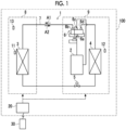
- FIG. 1 is a diagram showing an outline of an air conditioner according to a first embodiment of the present disclosure.
- an air conditioner 100 according to the present embodiment includes a refrigerant circuit 1, including a compressor 2, an indoor heat exchanger 3, an outdoor heat exchanger 4, an expansion valve 5, a four-way valve 6, and a refrigerant pipe 7 connecting these, and a control device 20 that controls the refrigerant circuit 1.
- a refrigerant circuit 1 including a compressor 2, an indoor heat exchanger 3, an outdoor heat exchanger 4, an expansion valve 5, a four-way valve 6, and a refrigerant pipe 7 connecting these, and a control device 20 that controls the refrigerant circuit 1.
- an indoor unit 8 is provided with the indoor heat exchanger 3
- an outdoor unit 9 is provided with the compressor 2, the outdoor heat exchanger 4, the expansion valve 5, and the four-way valve 6.
- the indoor unit 8 is provided with an indoor temperature sensor 11 that detects an indoor temperature of a room where the indoor unit 8 is installed and a radiation temperature sensor 13 that detects a radiation temperature from a wall or a floor of the room.
- the outdoor unit 9 is provided with an outdoor temperature sensor 12 that detects an outdoor temperature.
- a set temperature and an operation mode of the air conditioner 100 are set by a transmission and reception unit 30 such as a remote control operated by a user and a smartphone.
- the indoor temperature sensor 11 detects, for example, a temperature of air sucked by the indoor heat exchanger 3.
- the radiation temperature sensor 13 is, for example, a thermopile sensor and includes a thermopile (infrared sensor), an optical system that focuses infrared rays radiated from an object on the thermopile, and a signal processing circuit that processes an output signal of the thermopile.
- the set temperature is a target temperature for room temperature control.
- the operation mode is an operation method such as a heating operation and a cooling operation.
- the compressor 2 compresses a refrigerant and discharges and supplies the high-temperature and high-pressure refrigerant after compression to the refrigerant pipe 7.
- the high-pressure refrigerant compressed by the compressor 2 flows into a port 6a of the four-way valve 6 via the refrigerant pipe 7.
- the control device 20 controls the four-way valve 6 such that the port 6a and a port 6b of the four-way valve 6 are connected to each other and a port 6c and a port 6d are connected to each other. Accordingly, in the heating operation, the refrigerant flows in a direction of an arrow A1. That is, the high-temperature and high-pressure refrigerant is supplied to the indoor heat exchanger 3 via the four-way valve 6. The refrigerant radiates heat and is condensed and liquefied in the indoor heat exchanger 3. In addition, the refrigerant condensed in the indoor heat exchanger 3 is depressurized by the expansion valve 5 to become a low-pressure refrigerant.
- the low-pressure refrigerant is supplied to the outdoor heat exchanger 4 and vaporizes due to, for example, heat absorption from outside air. That is, in the heating operation, the indoor heat exchanger 3 functions as a condenser, and the outdoor heat exchanger 4 functions as an evaporator. In addition, the vaporized refrigerant is sucked by the compressor 2 via the four-way valve 6. The compressor compresses the low-pressure refrigerant again and discharges the high-temperature and high-pressure refrigerant.
- the control device 20 controls the four-way valve 6 such that the port 6a and the port 6d of the four-way valve 6 are connected to each other and the port 6b and the port 6c are connected to each other. Accordingly, in the cooling operation, the refrigerant flows in a direction of an arrow A2. That is, the high-temperature and high-pressure refrigerant is supplied to the outdoor heat exchanger 4 via the four-way valve 6, radiates heat to the outside air, and is condensed. In addition, the refrigerant condensed in the outdoor heat exchanger 4 is depressurized by the expansion valve 5 and is supplied to the indoor heat exchanger 3.
- the refrigerant is vaporized by, for example, heat absorption from indoor air. That is, in the cooling operation, the outdoor heat exchanger 4 functions as a condenser, and the indoor heat exchanger 3 functions as an evaporator. In addition, the vaporized refrigerant is sucked by the compressor 2 via the four-way valve 6. The compressor compresses the low-pressure refrigerant again and discharges the high-temperature and high-pressure refrigerant.
- the air conditioner 100 performs heating or cooling by repeating the above process to circulate the refrigerant.
- the control device 20 switches between the heating operation and the cooling operation by controlling the four-way valve 6.
- the control device 20 executes the heating operation or the cooling operation by adjusting a rotation speed of the compressor 2 such that the room temperature is the set temperature, based on a difference between the indoor temperature measured by the indoor temperature sensor 11 of the indoor heat exchanger 3 and the set temperature set by the user.
- the control device 20 controls the air conditioner 100 having the refrigerant circuit 1 that circulates the refrigerant compressed by the compressor 2 between the indoor heat exchanger 3 and the outdoor heat exchanger 4 such that a first deviation, which is a deviation of the indoor temperature from the set temperature, is small.
- the air conditioner 100 performs a defrosting operation of removing frost on the outdoor unit 9.
- the control device 20 switches the four-way valve 6 such that a circulation direction of the refrigerant is the same direction as in the cooling operation (the arrow A2 in Fig. 1 ). Accordingly, the outdoor unit 9 is defrosted by supplying the high-temperature and high-pressure refrigerant to the outdoor heat exchanger 4.
- Fig. 2 is a diagram showing a configuration example of the control device 20 according to the first embodiment of the present disclosure.
- Figs. 3 , 4 , 6 , and 7 are schematic diagrams for describing the control device 20 according to the first embodiment of the present disclosure.
- Fig. 5 is a flowchart showing an operation example of the control device 20 according to the first embodiment of the present disclosure.
- the control device 20 of the present embodiment includes an air conditioning control unit 21 as a functional configuration that can be configured by using a computer such as a microcomputer and that is configured by a combination of hardware, such as the computer, a peripheral circuit, and a peripheral device, and software, such as a program executed by the computer.
- the air conditioning control unit 21 includes a calculation unit 22 and a setting unit 23.
- the air conditioning control unit 21 inputs output signals of various types of sensors such as the indoor temperature sensor 11, the outdoor temperature sensor 12, the radiation temperature sensor 13, and a humidity sensor (not shown), transmits and receives a predetermined signal to and from the transmission and reception unit 30, and controls the compressor 2, the expansion valve 5, the four-way valve 6, a fan and a wind direction plate in the indoor unit 8 (not shown), a fan in the outdoor unit 9, and the like (hereinafter, referred to as the compressor 2 and the like) based on a set operation mode, the set temperature, and the like.
- sensors such as the indoor temperature sensor 11, the outdoor temperature sensor 12, the radiation temperature sensor 13, and a humidity sensor (not shown)
- the air conditioning control unit 21 controls the compressor 2 and the like such that the first deviation, which is the deviation of the indoor temperature from the set temperature, is small as described above.
- the air conditioning control unit 21 controls a maximum rotation speed of the compressor 2 based on a "set value" set by the setting unit 23 as will be described later.
- the maximum rotation speed of the compressor 2 is a maximum value (upper limit value) of the rotation speed when controlling the rotation speed of the compressor 2.
- the "set value" that is used as reference when controlling the maximum rotation speed of the compressor 2 may be, for example, a value of the maximum rotation speed itself or may be a predetermined reference value (for example, a value of a rotation speed that is lower than the maximum rotation speed by a predetermined rotation speed, a value that represents a range of a rotation speed having a predetermined width above and below the maximum rotation speed, and the like) that is used in a case where the rotation speed is controlled to be equal to or lower than the maximum rotation speed.
- the "set value” will also be referred to as a "compressor maximum rotation speed set value”.
- the calculation unit 22 calculates a first time until the first deviation becomes equal to or smaller than a first predetermined value.
- a first predetermined value the “first deviation”, the “first predetermined value”, and the “first time” will be described with reference to Fig. 3.
- Fig. 3 shows, with a solid line, an example of a change in the indoor temperature over time in a case where the air conditioner 100 is in the cooling operation.
- the "first deviation” is a deviation of the indoor temperature from the set temperature (a temperature difference between the set temperature and the indoor temperature) as described above.
- the “first deviation” is calculated by, for example, a calculation equation "(indoor temperature) - (set temperature)".
- the "first predetermined value” is a determination value corresponding to the first deviation in a case where it can be determined that the indoor temperature has almost reached the set temperature.
- the first predetermined value may be positive, negative, or zero.
- the first deviation is equal to or smaller than the first predetermined value.
- the "first time” is a time from when the air conditioner 100 starts the room temperature control (or changes control content) to when the indoor temperature reaches (or almost reaches) the set temperature, and in the example shown in Fig. 3 , is a time from time point t0 to time point t1.
- the time point t0 is, for example, an operation start time point of operating of the air conditioner 100, a time point of change of the set temperature, a time point of change of the operation mode, and the like.
- the "first time” is affected by an installation environment of the air conditioner 100 and is changed by, for example, a difference in heat insulating properties or air tightness of the room. In a case where the "first time” is relatively short, it can be said that, for example, the heat insulating properties are good, and in a case where the "first time” is relatively long, it can be said that, for example, the heat insulating properties are poor.
- the setting unit 23 sets the "set value" (compressor maximum rotation speed set value) based on the "first time” calculated by the calculation unit 22.
- Fig. 4 shows table T1 in which a setting example of the set value in the present embodiment is defined.
- the setting unit 23 decreases the set value from the current set value.
- the second threshold value is a value larger than the first threshold value.
- the setting unit 23 increases the set value from the current set value.
- the first threshold value is, for example, a determination value with which it can be determined that the heat insulating properties are good.
- the second threshold value is, for example, a determination value with which it can be determined that the heat insulating properties are poor.
- the setting of the "set value" by the setting unit 23 includes a case where the "set value” is changed and a case where the "set value” is not changed.
- the setting unit 23 increases or decreases the set value within a range of a limit on the upper limit value of the rotation speed, such as a maximum rated rotation speed, or a limit on a lower limit value of the predetermined rotation speed.
- the setting unit 23 determines that the heat insulating properties are good and lowers the set value (for example, 100 rps to 95 rps). In addition, in the next operation, once the set temperature is reached within A minutes from the start of the cooling operation, the setting unit 23 lowers the set value again (for example, 95 rps to 90 rps). In addition, in a case where the set temperature is not reached for B minutes (for example, 20 minutes) or more from the start of the operation, the setting unit 23 raises the set value (for example, 90 to 95 rps).
- the setting unit 23 does not change the set value in a case where the time taken to reach the set temperature is A to B minutes.
- the setting unit 23 automatically adjusts the set value (maximum rotation speed) of the compressor 2 to be suitable for the room where the air conditioner 100 is used by repeating this setting operation of the set value.
- the first threshold value shown in Fig. 4 corresponds to A minutes
- the second threshold value corresponds to B minutes.
- the rotation speed is changed by a predetermined rotation speed (for example, 5 rps).
- an increase/decrease amount is not limited to a constant and may be changed by, for example, a variable or a predetermined ratio with respect to the current set value.
- Fig. 5 shows an example of the setting operation of a set value by the control device 20.
- the processing shown in Fig. 5 is executed, for example, at the start of the operation of the air conditioner 100.
- the calculation unit 22 calculates the first time for which the first deviation, which is the deviation of the indoor temperature from the set temperature, becomes equal to or smaller than the first predetermined value (step S11).
- the setting unit 23 sets the set value of the maximum rotation speed of the compressor 2 based on the first time (step S12).
- Fig. 6 shows an example of a change in the rotation speed of the compressor 2 and the indoor temperature in the cooling operation of the air conditioner 100 over time.
- the operation is started at time point t0, and the rotation speed of the compressor 2 increases at a predetermined rate of change. Then, the rotation speed is controlled in the vicinity of the set value from time point t02 to time point t03 in a range that does not exceed the "set value" (compressor maximum rotation speed set value (before change)) at the start of the operation.
- set value compressor maximum rotation speed set value (before change)
- Fig. 7 shows an example of a change in the rotation speed of the compressor 2 before and after the change over time. In an operating example after the change, the operation time in the vicinity of the set value is extended compared to before the change, but an increase in the maximum rotation speed is suppressed.
- the higher the rotation speed of the compressor the larger the power consumption.
- Fig. 8 is a schematic diagram for describing a control device according to a second embodiment of the present disclosure.
- Fig. 8 shows an example of a change in the rotation speed of the compressor 2 and the indoor temperature in the cooling operation of the air conditioner 100 in the second embodiment over time.
- the configuration and the operation of the air conditioner 100 and the control device 20 described with reference to Figs. 1 to 5 are the same between the first embodiment and the second embodiment except for the following points. That is, in the first embodiment, as shown in Fig. 6 , the set value is changed in a case where the first time for which the first deviation becomes equal to or smaller than the first predetermined value has elapsed.
- the second embodiment as shown in Fig. 8 , the first time is predicted, and the set value is changed before the first time elapses. In this case, the calculation unit 22 of the second embodiment calculates the first time through prediction before the first time elapses.
- the calculation unit 22 of the second embodiment creates a regression model based on each of actual values, such as the set temperature, the indoor temperature, the outdoor temperature, the rotation speed of the compressor 2, and the first time, and predicts the first time using the created regression model.
- the calculation unit 22 of the second embodiment creates a trained machine learning model that is trained through machine learning based on at least each of actual values, such as the set temperature, the indoor temperature, the rotation speed of the compressor 2, and the first time, and predicts the first time using the created trained machine learning model.
- the indoor temperature may be only a value at the start of the operation or may include a plurality of time-series values before reaching the set temperature.
- the rotation speed may be only a value of the maximum rotation speed (set value) or may include the plurality of time-series values before reaching the set temperature.
- the calculation unit 22 of the second embodiment can change the set value in a case where the first time elapses, for example, like the calculation unit 22 of the first embodiment.
- the first time when the first time can be predicted before the rotation speed approaches around the maximum rotation speed (set value) (before time point t02) (time point t01 before time point t02), the set value can be changed (time point t01), and the change in the set value can be reflected (made valid) in the current operation.
- Fig. 9 is a flowchart showing an operation example of a control device according to a third embodiment of the present disclosure.
- Fig. 10 is a schematic diagram for describing the control device according to the third embodiment of the present disclosure.
- the configuration and the operation of the air conditioner 100 and the control device 20 described with reference to Figs. 1 to 3 are the same between the first embodiment and the third embodiment except for the following points. That is, the calculation unit 22 of the first embodiment calculates the first time until the first deviation becomes equal to or smaller than the first predetermined value. In addition, the setting unit 23 of the first embodiment sets the set value based on the first time.
- the calculation unit 22 of the third embodiment further calculates a second time until a second deviation, which is a deviation of the radiation temperature measured by the radiation temperature sensor 13 indoors from the set temperature, becomes equal to or smaller than a second predetermined value.
- the setting unit 23 of the third embodiment sets the set value based on the first time and the second time. The second deviation, the second predetermined value, and the second time correspond to a case where the indoor temperature in the first deviation, the first predetermined value, and the first time is replaced with the radiation temperature.
- the calculation unit 22 of the third embodiment calculates the first time for which the first deviation, which is the deviation of the indoor temperature from the set temperature, becomes equal to or smaller than the first predetermined value (step S31) and calculates the second time for which the second deviation, which is the deviation of the radiation temperature from the set temperature, becomes equal to or smaller than the second predetermined value (step S32).
- the setting unit 23 of the third embodiment sets the set value of the maximum rotation speed of the compressor 2 based on the first time and the second time (step S33).
- Fig. 10 shows table T3 in which a setting example of the set value in the present embodiment is defined.
- the setting unit 23 decreases the set value from the current set value when the second time is within a third threshold value and does not change the set value from the current set value when the second time is larger than the third threshold value.
- the third threshold value is a determination value for determining, for example, whether the heat insulating properties of the room are good or poor from a temperature change of the wall or the floor detected by the radiation temperature sensor.
- the setting unit 23 does not change the set value from the current set value when the second time is within the third threshold value and increases the set value from the current set value when the second time is larger than the third threshold value. In addition, in a case where the first time is equal to or larger than the second threshold value, the setting unit 23 increases the set value from the current set value.
- the maximum rotation speed can be adjusted according to the room in consideration of the temperature change of the floor or the wall in addition to the indoor temperature.
- Fig. 11 is a flowchart showing an operation example of a control device according to a fourth embodiment of the present disclosure.
- Fig. 12 is a schematic diagram for describing the control device according to the fourth embodiment of the present disclosure.
- the configuration and the operation of the air conditioner 100 and the control device 20 described with reference to Figs. 1 to 3 are the same between the first embodiment and the fourth embodiment except for the following points. That is, the calculation unit 22 of the first embodiment calculates the first time until the first deviation becomes equal to or smaller than the first predetermined value. In addition, the setting unit 23 of the first embodiment sets the set value based on the first time.
- the calculation unit 22 of the fourth embodiment further calculates a temperature difference between the set temperature and the indoor temperature at the start of the operation (however, the setting unit 23 may calculate the temperature difference, for example).
- the setting unit 23 of the third embodiment sets the set value based on the temperature difference between the set temperature and the indoor temperature at the start of the operation and the first time.
- the calculation unit 22 of the fourth embodiment calculates a temperature difference between the set temperature and the indoor temperature at the start of the operation (step S41) and calculates the first time for which the first deviation, which is the deviation of the indoor temperature from the set temperature, becomes equal to or smaller than the first predetermined value (step S42).
- the setting unit 23 of the fourth embodiment sets the set value of the maximum rotation speed of the compressor 2 based on the first time and the calculated temperature difference (step S43).
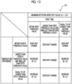
- Fig. 12 shows table T4 in which a setting example of the set value in the present embodiment is defined.
- the setting unit 23 does not change the set value when the temperature difference is within a fourth threshold value, decreases the set value by a change amount ⁇ 1 when the temperature difference is larger than the fourth threshold value and is smaller than a fifth threshold value, and decreases the set value by a change amount ⁇ 2 when the temperature difference is equal to or larger than the fifth threshold value.
- the change amount ⁇ 1 is smaller than the change amount ⁇ 2.
- the fourth threshold value is smaller than the fifth threshold value.
- the setting unit 23 does not change the set value.
- the setting unit 23 does not change the set value when the temperature difference is within the fourth threshold value, increases the set value by the change amount ⁇ 2 when the temperature difference is larger than the fourth threshold value and is smaller than the fifth threshold value, and increases the set value by the change amount ⁇ l when the temperature difference is equal to or larger than the fifth threshold value.
- the present embodiment for example, in a case where the temperature difference between the set temperature and the indoor temperature at the start of the operation is small (in a case where the temperature difference is within the fourth threshold value), it is possible to not change the set value without determining the heat insulating properties of the room or the like.
- the temperature difference is large (in a case where the temperature difference is equal to or larger than the fifth threshold value)
- a decrease amount when the maximum rotation speed is decreased can be made large, and an increase amount when the maximum rotation speed is increased can be made small, compared to a case where the temperature difference is not large (in a case where the temperature difference is smaller than the fifth threshold value).
- the maximum rotation speed can be adjusted according to the room in consideration of the temperature difference at the start of the operation in addition to the indoor temperature.
- the control device, the control method, and the air conditioner having the above configuration in the control of decreasing the first deviation, which is the deviation of the indoor temperature from the set temperature, the maximum rotation speed of the compressor is controlled based on the set value, which is set based on the first time until the first deviation becomes equal to or smaller than the first predetermined value.
- the first time is an element that is affected by the heat insulating properties of the room and the like
- the maximum rotation speed of the compressor is an element that affects power consumption. For this reason, adjusting the maximum rotation speed according to the first time is adjusting a degree of reduction in power consumption according to the heat insulating properties of the room or the like. Therefore, with the control device, the control method, and the air conditioner of the embodiment, both maintenance of comfort and reduction in power consumption can be achieved by adjusting the maximum rotation speed according to the first time.
- the maximum rotation speed is, for example, increased or decreased according to comparison results between the first time and a predetermined threshold value (the first threshold value and the second threshold value) in the above embodiments
- a raising width or a lowering width may be changed, for example, according to the magnitude of a difference between the first time and the predetermined threshold value, that is, the length of time until the set temperature is reached.
- actual values such as the outdoor temperature and humidity can be further used.
- a change in both temperatures may be considered, or one of the temperatures (for example, a temperature with a slower change) may be selectively considered.
- Fig. 13 is a schematic block diagram showing a configuration of a computer according to at least one embodiment.
- a computer 90 includes a processor 91, a main memory 92, a storage 93, and an interface 94.
- the control device 20 described above is mounted on the computer 90.
- An operation of each processing unit described above is stored in a form of a program in the storage 93.
- the processor 91 reads the program from the storage 93, deploys the program in the main memory 92, and executes the processing in accordance with the program.
- the processor 91 secures a storage area, which corresponds to each storage unit described above, in the main memory 92 in accordance with the program.
- the program may be a program for realizing some of the functions performed by the computer 90.
- the program may be a program that performs the functions in combination with other programs already stored in the storage or in combination with other programs installed in other devices.
- the computer may include a custom large scale integrated (LSI) circuit such as a programmable logic device (PLD) in addition to the above configuration or instead of the above configuration.
- PLD programmable logic device
- Examples of the PLD include a programmable array logic (PAL), a generic array logic (GAL), a complex programmable logic device (CPLD), and a field programmable gate array (FPGA).
- PAL programmable array logic
- GAL generic array logic
- CPLD complex programmable logic device
- FPGA field programmable gate array
- Examples of the storage 93 include a hard disk drive (HDD), a solid state drive (SSD), a magnetic disk, a magneto-optical disk, a compact disc read only memory (CD-ROM), a digital versatile disc read only memory (DVD-ROM), and a semiconductor memory.
- the storage 93 may be an internal medium directly connected to a bus of the computer 90 or may be an external medium connected to the computer 90 via the interface 94 or a communication line.
- the computer 90 that has received the distribution may deploy the program in the main memory 92 and execute the processing.
- the storage 93 is a non-transitory tangible storage medium.
- control device 20 described in each of the embodiments is understood as follows, for example.
Landscapes
- Engineering & Computer Science (AREA)
- Mechanical Engineering (AREA)
- General Engineering & Computer Science (AREA)
- Physics & Mathematics (AREA)
- Thermal Sciences (AREA)
- Chemical & Material Sciences (AREA)
- Combustion & Propulsion (AREA)
- Signal Processing (AREA)
- Fuzzy Systems (AREA)
- Mathematical Physics (AREA)
- Human Computer Interaction (AREA)
- Air Conditioning Control Device (AREA)
Abstract
Description
- The present disclosure relates to a control device, a control method, and an air conditioner.
- Priority is claimed on
Japanese Patent Application No. 2022-134898 filed on August 26, 2022 -
PTL 1 describes an air conditioner as follows. That is, the air conditioner described inPTL 1 detects a size, air tightness, and heat insulating properties of a room and regulates a wind direction, a wind amount, and a temperature correction amount at the start of an operation or every predetermined time according to the detection results. In the air conditioner described inPTL 1, for example, the air tightness and the heat insulating properties of the room are detected based on the detected size of the room and a temperature difference between a detected temperature after the start of the operation and a detected temperature after a predetermined time from the start of the operation. In addition, in the air conditioner described inPTL 1, a temperature correction amount is regulated by regulating a detected value of a room temperature sensor or a correction amount of a set temperature. With the air conditioner described inPTL 1, for example, it is possible to prevent a temperature of the room when a thermostat is turned off from becoming too low so that the room is cold during heating or becoming too low so that the room is hot during cooling or to suppress non-uniformity of an indoor temperature in a wide room. - [PTL 1] Japanese Unexamined Patent Application Publication No.
2017-203581 - However, since the air conditioner described in
PTL 1 is intended to maintain comfort, there is a problem in which appropriate air conditioning control is not always performed in some cases in order to improve energy saving performance. - The present disclosure has been made in order to solve the above problem, and an object of thereof is to provide a control device, a control method, and an air conditioner that can achieve both maintenance of comfort and reduction in power consumption.
- According to an aspect of the present disclosure, in order to solve the above problem, there is provided a control device that controls an air conditioner having a refrigerant circuit which circulates a refrigerant compressed by a compressor between an indoor heat exchanger and an outdoor heat exchanger such that a first deviation, which is a deviation of an indoor temperature from a set temperature, is small and that controls a maximum rotation speed of the compressor based on a predetermined set value, the control device including a calculation unit that calculates a first time until the first deviation becomes equal to or smaller than a first predetermined value and a setting unit that sets the set value based on the first time.
- According to another aspect of the present disclosure, there is provided a control method of controlling an air conditioner having a refrigerant circuit which circulates a refrigerant compressed by a compressor between an indoor heat exchanger and an outdoor heat exchanger such that a first deviation, which is a deviation of an indoor temperature from a set temperature, is small and controlling a maximum rotation speed of the compressor based on a predetermined set value, the control method including a step of calculating a first time until the first deviation becomes equal to or smaller than a first predetermined value and a step of setting the set value based on the first time.
- According to still another aspect of the present disclosure, there is provided an air conditioner including a refrigerant circuit that circulates a refrigerant compressed by a compressor between an indoor heat exchanger and an outdoor heat exchanger and a control device that controls a rotation speed of the compressor such that a first deviation, which is a deviation of an indoor temperature from a set temperature, is small, that controls a maximum rotation speed of the compressor based on a predetermined set value, and that has a calculation unit which calculates a first time until the first deviation becomes equal to or smaller than a first predetermined value and a setting unit which sets the set value based on the first time.
- With the control device, the control method, and the air conditioner of the present disclosure, both maintenance of comfort and reduction in power consumption can be achieved.
-
-
Fig. 1 is a diagram showing an outline of an air conditioner according to a first embodiment of the present disclosure. -
Fig. 2 is a diagram showing a configuration example of a control device according to the first embodiment of the present disclosure. -
Fig. 3 is a schematic diagram for describing the control device according to the first embodiment of the present disclosure. -
Fig. 4 is a schematic diagram for describing the control device according to the first embodiment of the present disclosure. -
Fig. 5 is a flowchart showing an operation example of the control device according to the first embodiment of the present disclosure. -
Fig. 6 is a schematic diagram for describing the control device according to the first embodiment of the present disclosure. -
Fig. 7 is a schematic diagram for describing the control device according to the first embodiment of the present disclosure. -
Fig. 8 is a schematic diagram for describing a control device according to a second embodiment of the present disclosure. -
Fig. 9 is a flowchart showing an operation example of a control device according to a third embodiment of the present disclosure. -
Fig. 10 is a schematic diagram for describing the control device according to the third embodiment of the present disclosure. -
Fig. 11 is a flowchart showing an operation example of a control device according to a fourth embodiment of the present disclosure. -
Fig. 12 is a schematic diagram for describing the control device according to the fourth embodiment of the present disclosure. -
Fig. 13 is a schematic block diagram showing a configuration of a computer according to at least one embodiment. - Hereinafter, a control device, a control method, and an air conditioner according to an embodiment of the present disclosure will be described with reference to the drawings. In each drawing, the same reference signs will be assigned to the same or corresponding configurations, and description thereof will be omitted as appropriate.
-
Fig. 1 is a diagram showing an outline of an air conditioner according to a first embodiment of the present disclosure. As shown inFig. 1 , anair conditioner 100 according to the present embodiment includes arefrigerant circuit 1, including acompressor 2, an indoor heat exchanger 3, an outdoor heat exchanger 4, anexpansion valve 5, a four-way valve 6, and arefrigerant pipe 7 connecting these, and acontrol device 20 that controls therefrigerant circuit 1. For example, anindoor unit 8 is provided with the indoor heat exchanger 3, and an outdoor unit 9 is provided with thecompressor 2, the outdoor heat exchanger 4, theexpansion valve 5, and the four-way valve 6. In addition, theindoor unit 8 is provided with an indoor temperature sensor 11 that detects an indoor temperature of a room where theindoor unit 8 is installed and aradiation temperature sensor 13 that detects a radiation temperature from a wall or a floor of the room. In addition, the outdoor unit 9 is provided with anoutdoor temperature sensor 12 that detects an outdoor temperature. In addition, in thecontrol device 20, for example, a set temperature and an operation mode of theair conditioner 100 are set by a transmission andreception unit 30 such as a remote control operated by a user and a smartphone. The indoor temperature sensor 11 detects, for example, a temperature of air sucked by the indoor heat exchanger 3. In addition, theradiation temperature sensor 13 is, for example, a thermopile sensor and includes a thermopile (infrared sensor), an optical system that focuses infrared rays radiated from an object on the thermopile, and a signal processing circuit that processes an output signal of the thermopile. The set temperature is a target temperature for room temperature control. The operation mode is an operation method such as a heating operation and a cooling operation. - The
compressor 2 compresses a refrigerant and discharges and supplies the high-temperature and high-pressure refrigerant after compression to therefrigerant pipe 7. The high-pressure refrigerant compressed by thecompressor 2 flows into a port 6a of the four-way valve 6 via therefrigerant pipe 7. - In the heating operation, the
control device 20 controls the four-way valve 6 such that the port 6a and aport 6b of the four-way valve 6 are connected to each other and aport 6c and a port 6d are connected to each other. Accordingly, in the heating operation, the refrigerant flows in a direction of an arrow A1. That is, the high-temperature and high-pressure refrigerant is supplied to the indoor heat exchanger 3 via the four-way valve 6. The refrigerant radiates heat and is condensed and liquefied in the indoor heat exchanger 3. In addition, the refrigerant condensed in the indoor heat exchanger 3 is depressurized by theexpansion valve 5 to become a low-pressure refrigerant. The low-pressure refrigerant is supplied to the outdoor heat exchanger 4 and vaporizes due to, for example, heat absorption from outside air. That is, in the heating operation, the indoor heat exchanger 3 functions as a condenser, and the outdoor heat exchanger 4 functions as an evaporator. In addition, the vaporized refrigerant is sucked by thecompressor 2 via the four-way valve 6. The compressor compresses the low-pressure refrigerant again and discharges the high-temperature and high-pressure refrigerant. - On the other hand, in the cooling operation, the
control device 20 controls the four-way valve 6 such that the port 6a and the port 6d of the four-way valve 6 are connected to each other and theport 6b and theport 6c are connected to each other. Accordingly, in the cooling operation, the refrigerant flows in a direction of an arrow A2. That is, the high-temperature and high-pressure refrigerant is supplied to the outdoor heat exchanger 4 via the four-way valve 6, radiates heat to the outside air, and is condensed. In addition, the refrigerant condensed in the outdoor heat exchanger 4 is depressurized by theexpansion valve 5 and is supplied to the indoor heat exchanger 3. In the indoor heat exchanger 3, the refrigerant is vaporized by, for example, heat absorption from indoor air. That is, in the cooling operation, the outdoor heat exchanger 4 functions as a condenser, and the indoor heat exchanger 3 functions as an evaporator. In addition, the vaporized refrigerant is sucked by thecompressor 2 via the four-way valve 6. The compressor compresses the low-pressure refrigerant again and discharges the high-temperature and high-pressure refrigerant. - The
air conditioner 100 performs heating or cooling by repeating the above process to circulate the refrigerant. Thecontrol device 20 switches between the heating operation and the cooling operation by controlling the four-way valve 6. In addition, thecontrol device 20 executes the heating operation or the cooling operation by adjusting a rotation speed of thecompressor 2 such that the room temperature is the set temperature, based on a difference between the indoor temperature measured by the indoor temperature sensor 11 of the indoor heat exchanger 3 and the set temperature set by the user. In this case, thecontrol device 20 according to the present embodiment controls theair conditioner 100 having therefrigerant circuit 1 that circulates the refrigerant compressed by thecompressor 2 between the indoor heat exchanger 3 and the outdoor heat exchanger 4 such that a first deviation, which is a deviation of the indoor temperature from the set temperature, is small. - In addition, when the heating operation is performed in an environment where an outside air temperature is low, frost adheres to the outdoor heat exchanger 4 in some cases. In order to prevent a decrease in a heating capacity caused by frosting, the
air conditioner 100 performs a defrosting operation of removing frost on the outdoor unit 9. In the defrosting operation, thecontrol device 20 switches the four-way valve 6 such that a circulation direction of the refrigerant is the same direction as in the cooling operation (the arrow A2 inFig. 1 ). Accordingly, the outdoor unit 9 is defrosted by supplying the high-temperature and high-pressure refrigerant to the outdoor heat exchanger 4. -
Fig. 2 is a diagram showing a configuration example of thecontrol device 20 according to the first embodiment of the present disclosure.Figs. 3 ,4 ,6 , and7 are schematic diagrams for describing thecontrol device 20 according to the first embodiment of the present disclosure.Fig. 5 is a flowchart showing an operation example of thecontrol device 20 according to the first embodiment of the present disclosure. - The
control device 20 of the present embodiment includes an airconditioning control unit 21 as a functional configuration that can be configured by using a computer such as a microcomputer and that is configured by a combination of hardware, such as the computer, a peripheral circuit, and a peripheral device, and software, such as a program executed by the computer. In addition, the airconditioning control unit 21 includes acalculation unit 22 and asetting unit 23. - The air
conditioning control unit 21 inputs output signals of various types of sensors such as the indoor temperature sensor 11, theoutdoor temperature sensor 12, theradiation temperature sensor 13, and a humidity sensor (not shown), transmits and receives a predetermined signal to and from the transmission andreception unit 30, and controls thecompressor 2, theexpansion valve 5, the four-way valve 6, a fan and a wind direction plate in the indoor unit 8 (not shown), a fan in the outdoor unit 9, and the like (hereinafter, referred to as thecompressor 2 and the like) based on a set operation mode, the set temperature, and the like. - In addition, in the present embodiment, the air
conditioning control unit 21 controls thecompressor 2 and the like such that the first deviation, which is the deviation of the indoor temperature from the set temperature, is small as described above. In this case, the airconditioning control unit 21 controls a maximum rotation speed of thecompressor 2 based on a "set value" set by the settingunit 23 as will be described later. The maximum rotation speed of thecompressor 2 is a maximum value (upper limit value) of the rotation speed when controlling the rotation speed of thecompressor 2. In addition, the "set value" that is used as reference when controlling the maximum rotation speed of thecompressor 2 may be, for example, a value of the maximum rotation speed itself or may be a predetermined reference value (for example, a value of a rotation speed that is lower than the maximum rotation speed by a predetermined rotation speed, a value that represents a range of a rotation speed having a predetermined width above and below the maximum rotation speed, and the like) that is used in a case where the rotation speed is controlled to be equal to or lower than the maximum rotation speed. Hereinafter, the "set value" will also be referred to as a "compressor maximum rotation speed set value". - In addition, the
calculation unit 22 according to the present embodiment calculates a first time until the first deviation becomes equal to or smaller than a first predetermined value. Herein, the "first deviation", the "first predetermined value", and the "first time" will be described with reference toFig. 3. Fig. 3 shows, with a solid line, an example of a change in the indoor temperature over time in a case where theair conditioner 100 is in the cooling operation. As shown inFig. 3 , the "first deviation" is a deviation of the indoor temperature from the set temperature (a temperature difference between the set temperature and the indoor temperature) as described above. The "first deviation" is calculated by, for example, a calculation equation "(indoor temperature) - (set temperature)". In addition, the "first predetermined value" is a determination value corresponding to the first deviation in a case where it can be determined that the indoor temperature has almost reached the set temperature. The first predetermined value may be positive, negative, or zero. In the example shown inFig. 3 , at time point t1, the first deviation is equal to or smaller than the first predetermined value. In addition, the "first time" is a time from when theair conditioner 100 starts the room temperature control (or changes control content) to when the indoor temperature reaches (or almost reaches) the set temperature, and in the example shown inFig. 3 , is a time from time point t0 to time point t1. The time point t0 is, for example, an operation start time point of operating of theair conditioner 100, a time point of change of the set temperature, a time point of change of the operation mode, and the like. The "first time" is affected by an installation environment of theair conditioner 100 and is changed by, for example, a difference in heat insulating properties or air tightness of the room. In a case where the "first time" is relatively short, it can be said that, for example, the heat insulating properties are good, and in a case where the "first time" is relatively long, it can be said that, for example, the heat insulating properties are poor. - In addition, the setting
unit 23 sets the "set value" (compressor maximum rotation speed set value) based on the "first time" calculated by thecalculation unit 22.Fig. 4 shows table T1 in which a setting example of the set value in the present embodiment is defined. According to table T1 shown inFig. 4 , for example, in a case where the first time is within a first threshold value, the settingunit 23 decreases the set value from the current set value. In a case where the first time is larger than the first threshold value and is smaller than a second threshold value, the settingunit 23 does not change the set value from the current set value. However, the second threshold value is a value larger than the first threshold value. In a case where the first time is equal to or larger than the second threshold value, the settingunit 23 increases the set value from the current set value. The first threshold value is, for example, a determination value with which it can be determined that the heat insulating properties are good. In addition, the second threshold value is, for example, a determination value with which it can be determined that the heat insulating properties are poor. In addition, in the present embodiment, the setting of the "set value" by the settingunit 23 includes a case where the "set value" is changed and a case where the "set value" is not changed. The settingunit 23 increases or decreases the set value within a range of a limit on the upper limit value of the rotation speed, such as a maximum rated rotation speed, or a limit on a lower limit value of the predetermined rotation speed. - For example, once the set temperature is reached within A minutes (for example, 10 minutes) from the start of the cooling operation, the setting
unit 23 determines that the heat insulating properties are good and lowers the set value (for example, 100 rps to 95 rps). In addition, in the next operation, once the set temperature is reached within A minutes from the start of the cooling operation, the settingunit 23 lowers the set value again (for example, 95 rps to 90 rps). In addition, in a case where the set temperature is not reached for B minutes (for example, 20 minutes) or more from the start of the operation, the settingunit 23 raises the set value (for example, 90 to 95 rps). In addition, the settingunit 23 does not change the set value in a case where the time taken to reach the set temperature is A to B minutes. The settingunit 23 automatically adjusts the set value (maximum rotation speed) of thecompressor 2 to be suitable for the room where theair conditioner 100 is used by repeating this setting operation of the set value. In this example, the first threshold value shown inFig. 4 corresponds to A minutes, and the second threshold value corresponds to B minutes. In addition, in a case of lowering or raising the rotation speed, the rotation speed is changed by a predetermined rotation speed (for example, 5 rps). However, an increase/decrease amount is not limited to a constant and may be changed by, for example, a variable or a predetermined ratio with respect to the current set value. -
Fig. 5 shows an example of the setting operation of a set value by thecontrol device 20. The processing shown inFig. 5 is executed, for example, at the start of the operation of theair conditioner 100. In the processing shown inFig. 5 , first, thecalculation unit 22 calculates the first time for which the first deviation, which is the deviation of the indoor temperature from the set temperature, becomes equal to or smaller than the first predetermined value (step S11). Next, the settingunit 23 sets the set value of the maximum rotation speed of thecompressor 2 based on the first time (step S12). -
Fig. 6 shows an example of a change in the rotation speed of thecompressor 2 and the indoor temperature in the cooling operation of theair conditioner 100 over time. In the example shown inFig. 6 , the operation is started at time point t0, and the rotation speed of thecompressor 2 increases at a predetermined rate of change. Then, the rotation speed is controlled in the vicinity of the set value from time point t02 to time point t03 in a range that does not exceed the "set value" (compressor maximum rotation speed set value (before change)) at the start of the operation. Then, after time point t03, the rotation speed gradually decreases, the first deviation is equal to or smaller than the first predetermined value at time point t1, and the set value is changed (decreased) from the compressor maximum rotation speed set value (before change) to the compressor maximum rotation speed set value (after change). In the example shown inFig. 6 , the set value is changed after the rotation speed of thecompressor 2 reaches around the maximum rotation speed and is further decreased. Therefore, the changed set value is valid from the next operation.Fig. 7 shows an example of a change in the rotation speed of thecompressor 2 before and after the change over time. In an operating example after the change, the operation time in the vicinity of the set value is extended compared to before the change, but an increase in the maximum rotation speed is suppressed. - Basically, the higher the rotation speed of the compressor, the larger the power consumption. According to the present embodiment, it is possible to suppress an increase in power consumption without impairing comfort by adjusting the maximum rotation speed according to the room. That is, according to the present embodiment, both maintenance of comfort and reduction in power consumption can be achieved.
-
Fig. 8 is a schematic diagram for describing a control device according to a second embodiment of the present disclosure.Fig. 8 shows an example of a change in the rotation speed of thecompressor 2 and the indoor temperature in the cooling operation of theair conditioner 100 in the second embodiment over time. The configuration and the operation of theair conditioner 100 and thecontrol device 20 described with reference toFigs. 1 to 5 are the same between the first embodiment and the second embodiment except for the following points. That is, in the first embodiment, as shown inFig. 6 , the set value is changed in a case where the first time for which the first deviation becomes equal to or smaller than the first predetermined value has elapsed. On the other hand, in the second embodiment, as shown inFig. 8 , the first time is predicted, and the set value is changed before the first time elapses. In this case, thecalculation unit 22 of the second embodiment calculates the first time through prediction before the first time elapses. - The
calculation unit 22 of the second embodiment creates a regression model based on each of actual values, such as the set temperature, the indoor temperature, the outdoor temperature, the rotation speed of thecompressor 2, and the first time, and predicts the first time using the created regression model. For example, thecalculation unit 22 of the second embodiment creates a trained machine learning model that is trained through machine learning based on at least each of actual values, such as the set temperature, the indoor temperature, the rotation speed of thecompressor 2, and the first time, and predicts the first time using the created trained machine learning model. In this case, the indoor temperature may be only a value at the start of the operation or may include a plurality of time-series values before reaching the set temperature. In addition, the rotation speed may be only a value of the maximum rotation speed (set value) or may include the plurality of time-series values before reaching the set temperature. - Until the regression model can be created by acquiring a plurality of actual values, the
calculation unit 22 of the second embodiment can change the set value in a case where the first time elapses, for example, like thecalculation unit 22 of the first embodiment. - According to the second embodiment, for example, as shown in
Fig. 8 , when the first time can be predicted before the rotation speed approaches around the maximum rotation speed (set value) (before time point t02) (time point t01 before time point t02), the set value can be changed (time point t01), and the change in the set value can be reflected (made valid) in the current operation. -
Fig. 9 is a flowchart showing an operation example of a control device according to a third embodiment of the present disclosure.Fig. 10 is a schematic diagram for describing the control device according to the third embodiment of the present disclosure. The configuration and the operation of theair conditioner 100 and thecontrol device 20 described with reference toFigs. 1 to 3 are the same between the first embodiment and the third embodiment except for the following points. That is, thecalculation unit 22 of the first embodiment calculates the first time until the first deviation becomes equal to or smaller than the first predetermined value. In addition, the settingunit 23 of the first embodiment sets the set value based on the first time. On the other hand, thecalculation unit 22 of the third embodiment further calculates a second time until a second deviation, which is a deviation of the radiation temperature measured by theradiation temperature sensor 13 indoors from the set temperature, becomes equal to or smaller than a second predetermined value. In addition, the settingunit 23 of the third embodiment sets the set value based on the first time and the second time. The second deviation, the second predetermined value, and the second time correspond to a case where the indoor temperature in the first deviation, the first predetermined value, and the first time is replaced with the radiation temperature. - As shown in
Fig. 9 , in thecontrol device 20 of the third embodiment, first, thecalculation unit 22 of the third embodiment calculates the first time for which the first deviation, which is the deviation of the indoor temperature from the set temperature, becomes equal to or smaller than the first predetermined value (step S31) and calculates the second time for which the second deviation, which is the deviation of the radiation temperature from the set temperature, becomes equal to or smaller than the second predetermined value (step S32). Next, the settingunit 23 of the third embodiment sets the set value of the maximum rotation speed of thecompressor 2 based on the first time and the second time (step S33). -
Fig. 10 shows table T3 in which a setting example of the set value in the present embodiment is defined. According to table T3 shown inFig. 10 , for example, in a case where the first time is within the first threshold value, the settingunit 23 decreases the set value from the current set value when the second time is within a third threshold value and does not change the set value from the current set value when the second time is larger than the third threshold value. Herein, the third threshold value is a determination value for determining, for example, whether the heat insulating properties of the room are good or poor from a temperature change of the wall or the floor detected by the radiation temperature sensor. In addition, in a case where the first time is larger than the first threshold value and is smaller than the second threshold value, the settingunit 23 does not change the set value from the current set value when the second time is within the third threshold value and increases the set value from the current set value when the second time is larger than the third threshold value. In addition, in a case where the first time is equal to or larger than the second threshold value, the settingunit 23 increases the set value from the current set value. - According to the present embodiment, the maximum rotation speed can be adjusted according to the room in consideration of the temperature change of the floor or the wall in addition to the indoor temperature.
-
Fig. 11 is a flowchart showing an operation example of a control device according to a fourth embodiment of the present disclosure.Fig. 12 is a schematic diagram for describing the control device according to the fourth embodiment of the present disclosure. The configuration and the operation of theair conditioner 100 and thecontrol device 20 described with reference toFigs. 1 to 3 are the same between the first embodiment and the fourth embodiment except for the following points. That is, thecalculation unit 22 of the first embodiment calculates the first time until the first deviation becomes equal to or smaller than the first predetermined value. In addition, the settingunit 23 of the first embodiment sets the set value based on the first time. On the other hand, thecalculation unit 22 of the fourth embodiment further calculates a temperature difference between the set temperature and the indoor temperature at the start of the operation (however, the settingunit 23 may calculate the temperature difference, for example). In addition, the settingunit 23 of the third embodiment sets the set value based on the temperature difference between the set temperature and the indoor temperature at the start of the operation and the first time. - As shown in
Fig. 12 , in thecontrol device 20 of the fourth embodiment, first, thecalculation unit 22 of the fourth embodiment calculates a temperature difference between the set temperature and the indoor temperature at the start of the operation (step S41) and calculates the first time for which the first deviation, which is the deviation of the indoor temperature from the set temperature, becomes equal to or smaller than the first predetermined value (step S42). Next, the settingunit 23 of the fourth embodiment sets the set value of the maximum rotation speed of thecompressor 2 based on the first time and the calculated temperature difference (step S43). -
Fig. 12 shows table T4 in which a setting example of the set value in the present embodiment is defined. According to table T4 shown inFig. 12 , for example, in a case where the first time is within the first threshold value, the settingunit 23 does not change the set value when the temperature difference is within a fourth threshold value, decreases the set value by a change amount Δ1 when the temperature difference is larger than the fourth threshold value and is smaller than a fifth threshold value, and decreases the set value by a change amount Δ2 when the temperature difference is equal to or larger than the fifth threshold value. The change amount Δ1 is smaller than the change amount Δ2. In addition, the fourth threshold value is smaller than the fifth threshold value. In addition, in a case where the first time is larger than the first threshold value and is smaller than the second threshold value, the settingunit 23 does not change the set value. In addition, in a case where the first time is equal to or larger than the second threshold value, the settingunit 23 does not change the set value when the temperature difference is within the fourth threshold value, increases the set value by the change amount Δ2 when the temperature difference is larger than the fourth threshold value and is smaller than the fifth threshold value, and increases the set value by the change amount Δl when the temperature difference is equal to or larger than the fifth threshold value. - According to the present embodiment, for example, in a case where the temperature difference between the set temperature and the indoor temperature at the start of the operation is small (in a case where the temperature difference is within the fourth threshold value), it is possible to not change the set value without determining the heat insulating properties of the room or the like. In addition, for example, in a case where the temperature difference is large (in a case where the temperature difference is equal to or larger than the fifth threshold value), a decrease amount when the maximum rotation speed is decreased can be made large, and an increase amount when the maximum rotation speed is increased can be made small, compared to a case where the temperature difference is not large (in a case where the temperature difference is smaller than the fifth threshold value). According to the present embodiment, the maximum rotation speed can be adjusted according to the room in consideration of the temperature difference at the start of the operation in addition to the indoor temperature.
- In the control device, the control method, and the air conditioner having the above configuration, in the control of decreasing the first deviation, which is the deviation of the indoor temperature from the set temperature, the maximum rotation speed of the compressor is controlled based on the set value, which is set based on the first time until the first deviation becomes equal to or smaller than the first predetermined value. The first time is an element that is affected by the heat insulating properties of the room and the like, and the maximum rotation speed of the compressor is an element that affects power consumption. For this reason, adjusting the maximum rotation speed according to the first time is adjusting a degree of reduction in power consumption according to the heat insulating properties of the room or the like. Therefore, with the control device, the control method, and the air conditioner of the embodiment, both maintenance of comfort and reduction in power consumption can be achieved by adjusting the maximum rotation speed according to the first time.
- Although the embodiments of the present disclosure have been described in detail with reference to the drawings hereinbefore, a specific configuration is not limited to the embodiments, and design changes or the like are also included without departing from the gist of the present disclosure. For example, configurations and operations of respective embodiments can be combined as appropriate. Although the maximum rotation speed is, for example, increased or decreased according to comparison results between the first time and a predetermined threshold value (the first threshold value and the second threshold value) in the above embodiments, a raising width or a lowering width may be changed, for example, according to the magnitude of a difference between the first time and the predetermined threshold value, that is, the length of time until the set temperature is reached. In addition, when creating the regression model, actual values such as the outdoor temperature and humidity can be further used. In addition, in a case where the indoor temperature and the radiation temperature are considered, a change in both temperatures may be considered, or one of the temperatures (for example, a temperature with a slower change) may be selectively considered.
-
Fig. 13 is a schematic block diagram showing a configuration of a computer according to at least one embodiment. - A
computer 90 includes aprocessor 91, amain memory 92, astorage 93, and aninterface 94. - The
control device 20 described above is mounted on thecomputer 90. An operation of each processing unit described above is stored in a form of a program in thestorage 93. Theprocessor 91 reads the program from thestorage 93, deploys the program in themain memory 92, and executes the processing in accordance with the program. In addition, theprocessor 91 secures a storage area, which corresponds to each storage unit described above, in themain memory 92 in accordance with the program. - The program may be a program for realizing some of the functions performed by the
computer 90. For example, the program may be a program that performs the functions in combination with other programs already stored in the storage or in combination with other programs installed in other devices. In other embodiments, the computer may include a custom large scale integrated (LSI) circuit such as a programmable logic device (PLD) in addition to the above configuration or instead of the above configuration. Examples of the PLD include a programmable array logic (PAL), a generic array logic (GAL), a complex programmable logic device (CPLD), and a field programmable gate array (FPGA). In this case, some or all of the functions realized by the processor may be realized by the integrated circuit. - Examples of the
storage 93 include a hard disk drive (HDD), a solid state drive (SSD), a magnetic disk, a magneto-optical disk, a compact disc read only memory (CD-ROM), a digital versatile disc read only memory (DVD-ROM), and a semiconductor memory. Thestorage 93 may be an internal medium directly connected to a bus of thecomputer 90 or may be an external medium connected to thecomputer 90 via theinterface 94 or a communication line. In addition, in a case where the program is distributed to thecomputer 90 via the communication line, thecomputer 90 that has received the distribution may deploy the program in themain memory 92 and execute the processing. In at least one embodiment, thestorage 93 is a non-transitory tangible storage medium. - The
control device 20 described in each of the embodiments is understood as follows, for example. - (1) The
control device 20 according to a first aspect is thecontrol device 20 that controls theair conditioner 100 having therefrigerant circuit 1 which circulates a refrigerant compressed by thecompressor 2 between the indoor heat exchanger 3 and the outdoor heat exchanger 4 such that a first deviation, which is a deviation of an indoor temperature from a set temperature, is small and that controls a maximum rotation speed of thecompressor 2 based on a predetermined set value and includes thecalculation unit 22 that calculates a first time until the first deviation becomes equal to or smaller than a first predetermined value and thesetting unit 23 that sets the set value based on the first time. According to the present aspect and each of the following aspects, both maintenance of comfort and reduction in power consumption can be achieved. - (2) The
control device 20 according to a second aspect is thecontrol device 20 of (1). The settingunit 23 decreases the set value in a case where the first time is equal to or smaller than the first threshold value, does not change the set value in a case where the first time is smaller than a second threshold value, which is larger than the first threshold value, and is larger than the first threshold value, and increases the set value in a case where the first time is equal to or larger than the second threshold value. - (3) The
control device 20 according to a third aspect is thecontrol device 20 of (1) or (2). Thecalculation unit 22 calculates the first time through prediction before the first time elapses. - (4) The
control device 20 according to a fourth aspect is thecontrol device 20 of (1) to (3). Thecalculation unit 22 predicts the first time using a trained machine learning model that is trained through machine learning based on at least each of actual values of the set temperature, the indoor temperature, the rotation speed, and the first time. - (5) The
control device 20 according to a fifth aspect is thecontrol device 20 of (1) to (4). Thecalculation unit 22 further calculates a second time until a second deviation, which is a deviation of a radiation temperature measured by a radiation temperature sensor indoors from the set temperature, becomes equal to or smaller than a second predetermined value, and thesetting unit 23 sets the set value based on the first time and the second time. According to the present aspect, the maximum rotation speed can be set in consideration of the temperature change of the wall or the floor of the room. - (6) The
control device 20 according to a sixth aspect is thecontrol device 20 of (1) to (5). The setting unit sets the set value based on a temperature difference between the set temperature and the indoor temperature at start of an operation and the first time. - According to the aspect described above, both maintenance of comfort and reduction in power consumption can be achieved.
-
- 100 air conditioner
- 1 refrigerant circuit
- 2 compressor
- 3 indoor heat exchanger
- 4 outdoor heat exchanger
- 5 expansion valve
- 6 four-way valve
- 7 refrigerant pipe
- 8 indoor unit
- 9 outdoor unit
- 11 indoor temperature sensor
- 12 outdoor temperature sensor
- 13 radiation temperature sensor
- 20 control device
- 21 air conditioning control unit
- 22 calculation unit
- 23 setting unit
Claims (8)
- A control device that controls an air conditioner having a refrigerant circuit which circulates a refrigerant compressed by a compressor between an indoor heat exchanger and an outdoor heat exchanger such that a first deviation, which is a deviation of an indoor temperature from a set temperature, is small and that controls a maximum rotation speed of the compressor based on a predetermined set value, the control device comprising:a calculation unit that calculates a first time until the first deviation becomes equal to or smaller than a first predetermined value; anda setting unit that sets the set value based on the first time.
- The control device according to Claim 1,
wherein the setting unit decreases the set value in a case where the first time is equal to or smaller than the first threshold value, does not change the set value in a case where the first time is smaller than a second threshold value, which is larger than the first threshold value, and is larger than the first threshold value, and increases the set value in a case where the first time is equal to or larger than the second threshold value. - The control device according to Claim 2,
wherein the calculation unit calculates the first time through prediction before the first time elapses. - The control device according to Claim 3,
wherein the calculation unit predicts the first time using a trained machine learning model that is trained through machine learning based on at least each of actual values of the set temperature, the indoor temperature, the maximum rotation speed, and the first time. - The control device according to Claim 4,wherein the calculation unit further calculates a second time until a second deviation, which is a deviation of a radiation temperature measured by a radiation temperature sensor indoors from the set temperature, becomes equal to or smaller than a second predetermined value, andthe setting unit sets the set value based on the first time and the second time.
- The control device according to Claim 5,
wherein the setting unit sets the set value based on a temperature difference between the set temperature and the indoor temperature at start of an operation and the first time. - A control method of controlling an air conditioner having a refrigerant circuit which circulates a refrigerant compressed by a compressor between an indoor heat exchanger and an outdoor heat exchanger such that a first deviation, which is a deviation of an indoor temperature from a set temperature, is small and controlling a maximum rotation speed of the compressor based on a predetermined set value, the control method comprising:a step of calculating a first time until the first deviation becomes equal to or smaller than a first predetermined value; anda step of setting the set value based on the first time.
- An air conditioner comprising:a refrigerant circuit that circulates a refrigerant compressed by a compressor between an indoor heat exchanger and an outdoor heat exchanger; anda control device that controls a rotation speed of the compressor such that a first deviation, which is a deviation of an indoor temperature from a set temperature, is small, that controls a maximum rotation speed of the compressor based on a predetermined set value, and that has a calculation unit which calculates a first time until the first deviation becomes equal to or smaller than a first predetermined value and a setting unit which sets the set value based on the first time.
Applications Claiming Priority (2)
| Application Number | Priority Date | Filing Date | Title |
|---|---|---|---|
| JP2022134898A JP2024031381A (en) | 2022-08-26 | 2022-08-26 | Control device, control method and air conditioner |
| PCT/JP2023/029993 WO2024043206A1 (en) | 2022-08-26 | 2023-08-21 | Control device, control method, and air conditioner |
Publications (2)
| Publication Number | Publication Date |
|---|---|
| EP4560215A1 true EP4560215A1 (en) | 2025-05-28 |
| EP4560215A4 EP4560215A4 (en) | 2025-11-26 |
Family
ID=90013289
Family Applications (1)
| Application Number | Title | Priority Date | Filing Date |
|---|---|---|---|
| EP23857317.4A Pending EP4560215A4 (en) | 2022-08-26 | 2023-08-21 | CONTROL DEVICE, CONTROL METHOD AND AIR CONDITIONING SYSTEM |
Country Status (4)
| Country | Link |
|---|---|
| EP (1) | EP4560215A4 (en) |
| JP (1) | JP2024031381A (en) |
| AU (1) | AU2023331083A1 (en) |
| WO (1) | WO2024043206A1 (en) |
Families Citing this family (1)
| Publication number | Priority date | Publication date | Assignee | Title |
|---|---|---|---|---|
| WO2025220665A1 (en) * | 2024-04-15 | 2025-10-23 | 三菱重工サーマルシステムズ株式会社 | Control system, air conditioning system, control method, and program |
Family Cites Families (7)
| Publication number | Priority date | Publication date | Assignee | Title |
|---|---|---|---|---|
| JPH11173633A (en) * | 1997-12-09 | 1999-07-02 | Sanyo Electric Co Ltd | Heating system |
| EP1834138B1 (en) * | 2005-01-03 | 2017-08-02 | Arçelik Anonim Sirketi | A cooling device and a control method |
| DE102006044999B4 (en) * | 2005-09-29 | 2010-04-01 | Danfoss Compressors Gmbh | Method and control unit for controlling a rotational speed of a compressor |
| JP6746202B2 (en) | 2016-05-11 | 2020-08-26 | 日立ジョンソンコントロールズ空調株式会社 | Air conditioner |
| JP6941819B2 (en) * | 2019-09-24 | 2021-09-29 | パナソニックIpマネジメント株式会社 | How to start the operation of the air conditioner and the control device |
| WO2021117234A1 (en) * | 2019-12-13 | 2021-06-17 | 三菱電機株式会社 | Model sharing system, model management apparatus, and control apparatus for air conditioning apparatus |
| JP2022134898A (en) | 2021-03-04 | 2022-09-15 | 住友重機械イオンテクノロジー株式会社 | Ion implantation device and ion implantation method |
-
2022
- 2022-08-26 JP JP2022134898A patent/JP2024031381A/en active Pending
-
2023
- 2023-08-21 WO PCT/JP2023/029993 patent/WO2024043206A1/en not_active Ceased
- 2023-08-21 AU AU2023331083A patent/AU2023331083A1/en active Pending
- 2023-08-21 EP EP23857317.4A patent/EP4560215A4/en active Pending
Also Published As
| Publication number | Publication date |
|---|---|
| WO2024043206A1 (en) | 2024-02-29 |
| AU2023331083A1 (en) | 2025-03-13 |
| EP4560215A4 (en) | 2025-11-26 |
| JP2024031381A (en) | 2024-03-07 |
Similar Documents
| Publication | Publication Date | Title |
|---|---|---|
| CN111174372B (en) | Air conditioner control method and device, storage medium and air conditioner | |
| CN113091215B (en) | Heating control method of air conditioner | |
| US9074787B2 (en) | Operation controller for compressor and air conditioner having the same | |
| CN107178873B (en) | Variable frequency air conditioner and control method thereof | |
| CN114251802B (en) | Dehumidification control method, air conditioner and readable storage medium | |
| US20190086113A1 (en) | Air conditioning system | |
| KR102558826B1 (en) | Air conditioner system and control method | |
| US10712067B2 (en) | Air-conditioning apparatus | |
| US20190293311A1 (en) | Air conditioning apparatus and air conditioning control method | |
| EP3859244B1 (en) | Air-conditioner | |
| CN113566375B (en) | Air conditioner control method and control device and air conditioner | |
| CN115095955B (en) | Air conditioner and defrosting control method thereof | |
| US20160153686A1 (en) | Air-conditioning apparatus | |
| US20220228765A1 (en) | Proactive system control using humidity prediction | |
| WO2024109148A1 (en) | Air conditioner and control method therefor | |
| CN111780371B (en) | Energy-saving control method and device for air conditioner and storage medium | |
| AU2023331083A1 (en) | Control device, control method, and air conditioner | |
| EP3255353B1 (en) | Method and apparatus for optimizing latent capacity of a variable speed compressor system | |
| JP2017096529A (en) | Control device, air conditioning system including the same, control method and control program | |
| CN112856712A (en) | Expansion valve control method and device | |
| CN115900048B (en) | Noise control methods for multi-split air conditioners | |
| CN111550910A (en) | Variable-frequency precision air conditioner and dehumidification control method and storage medium thereof | |
| JP2020029990A (en) | Air conditioner | |
| CN115638509B (en) | Air conditioning control method, device, air conditioning and storage medium | |
| JP7199529B2 (en) | Control device, air environment adjustment system, air environment adjustment method, program, and recording medium |
Legal Events
| Date | Code | Title | Description |
|---|---|---|---|
| STAA | Information on the status of an ep patent application or granted ep patent |
Free format text: STATUS: THE INTERNATIONAL PUBLICATION HAS BEEN MADE |
|
| PUAI | Public reference made under article 153(3) epc to a published international application that has entered the european phase |
Free format text: ORIGINAL CODE: 0009012 |
|
| STAA | Information on the status of an ep patent application or granted ep patent |
Free format text: STATUS: REQUEST FOR EXAMINATION WAS MADE |
|
| 17P | Request for examination filed |
Effective date: 20250221 |
|
| AK | Designated contracting states |
Kind code of ref document: A1 Designated state(s): AL AT BE BG CH CY CZ DE DK EE ES FI FR GB GR HR HU IE IS IT LI LT LU LV MC ME MK MT NL NO PL PT RO RS SE SI SK SM TR |
|
| XX | Miscellaneous (additional remarks) |
Free format text: A REQUEST FOR CORRECTION TO THE DESCRIPTION HAS BEEN FILED PURSUANT TO RULE 139 EPC. A DECISION ON THE REQUEST WILL BE TAKEN DURING THE PROCEEDINGS BEFORE THE EXAMINING DIVISION (GUIDELINES FOR EXAMINATION IN THE EPO, A-V, 3). |
|
| A4 | Supplementary search report drawn up and despatched |
Effective date: 20251023 |
|
| RIC1 | Information provided on ipc code assigned before grant |
Ipc: F24F 11/46 20180101AFI20251017BHEP Ipc: F24F 11/64 20180101ALI20251017BHEP Ipc: F24F 11/86 20180101ALI20251017BHEP |
|
| DAV | Request for validation of the european patent (deleted) | ||
| DAX | Request for extension of the european patent (deleted) |