EP4560205A1 - Outdoor unit for a heat pump system - Google Patents
Outdoor unit for a heat pump system Download PDFInfo
- Publication number
- EP4560205A1 EP4560205A1 EP23211294.6A EP23211294A EP4560205A1 EP 4560205 A1 EP4560205 A1 EP 4560205A1 EP 23211294 A EP23211294 A EP 23211294A EP 4560205 A1 EP4560205 A1 EP 4560205A1
- Authority
- EP
- European Patent Office
- Prior art keywords
- gas
- outdoor unit
- heat medium
- plate
- liquid separator
- Prior art date
- Legal status (The legal status is an assumption and is not a legal conclusion. Google has not performed a legal analysis and makes no representation as to the accuracy of the status listed.)
- Pending
Links
Images
Classifications
-
- F—MECHANICAL ENGINEERING; LIGHTING; HEATING; WEAPONS; BLASTING
- F24—HEATING; RANGES; VENTILATING
- F24F—AIR-CONDITIONING; AIR-HUMIDIFICATION; VENTILATION; USE OF AIR CURRENTS FOR SCREENING
- F24F5/00—Air-conditioning systems or apparatus not covered by F24F1/00 or F24F3/00, e.g. using solar heat or combined with household units such as an oven or water heater
- F24F5/0003—Exclusively-fluid systems
-
- F—MECHANICAL ENGINEERING; LIGHTING; HEATING; WEAPONS; BLASTING
- F24—HEATING; RANGES; VENTILATING
- F24F—AIR-CONDITIONING; AIR-HUMIDIFICATION; VENTILATION; USE OF AIR CURRENTS FOR SCREENING
- F24F1/00—Room units for air-conditioning, e.g. separate or self-contained units or units receiving primary air from a central station
- F24F1/06—Separate outdoor units, e.g. outdoor unit to be linked to a separate room comprising a compressor and a heat exchanger
- F24F1/14—Heat exchangers specially adapted for separate outdoor units
-
- F—MECHANICAL ENGINEERING; LIGHTING; HEATING; WEAPONS; BLASTING
- F25—REFRIGERATION OR COOLING; COMBINED HEATING AND REFRIGERATION SYSTEMS; HEAT PUMP SYSTEMS; MANUFACTURE OR STORAGE OF ICE; LIQUEFACTION SOLIDIFICATION OF GASES
- F25B—REFRIGERATION MACHINES, PLANTS OR SYSTEMS; COMBINED HEATING AND REFRIGERATION SYSTEMS; HEAT PUMP SYSTEMS
- F25B13/00—Compression machines, plants or systems, with reversible cycle
-
- F—MECHANICAL ENGINEERING; LIGHTING; HEATING; WEAPONS; BLASTING
- F25—REFRIGERATION OR COOLING; COMBINED HEATING AND REFRIGERATION SYSTEMS; HEAT PUMP SYSTEMS; MANUFACTURE OR STORAGE OF ICE; LIQUEFACTION SOLIDIFICATION OF GASES
- F25B—REFRIGERATION MACHINES, PLANTS OR SYSTEMS; COMBINED HEATING AND REFRIGERATION SYSTEMS; HEAT PUMP SYSTEMS
- F25B2313/00—Compression machines, plants or systems with reversible cycle not otherwise provided for
- F25B2313/004—Outdoor unit with water as a heat sink or heat source
Definitions
- the present invention relates to an outdoor unit for a heat pump system.
- refrigerants such as R290 are set to replace previous refrigerants currently being phased out.
- Such new refrigerants are characterized by a high volatility and flammability, and are likely to cause explosions should they leak and accumulate near sources of ignition.
- One way a refrigerant may inadvertently be released from a heat pump system is by leaking into heat medium piping, thereby being able to travel along with said medium from the outdoor unit, and into an indoor unit, causing said refrigerant to be released indoor.
- a possible countermeasure consists in the placement of a gas-liquid separator at or near the heat medium output piping of an outdoor unit. These gas-liquid separator are often placed downstream of the outdoor unit.
- piping having multiple connection points is used in piping connecting the outdoor unit to the gas-liquid separator, there is a risk that refrigerant will leak from the connection points. This leads to the issue that, the more connection points are present, the greater the risk of leakage becomes.
- the present invention aims to resolve at least some of the problems and disadvantages mentioned above.
- the present invention aims to resolve at least some of the problems and disadvantages mentioned above.
- the invention thereto aims to provide an outdoor unit for a heat pump system using a flammable, combustible and/or explosive refrigerant.
- said outdoor unit comprises:
- the plate heat exchanger has a first side wall where a first inlet port and a first outlet port are provided, and the plate heat exchanger is arranged in the outdoor unit so that the first side wall of the plate heat exchanger is adjacent to the inner surface of the rear plate, or adjacent to the inner surface of the first side plate.
- a first and a second heat medium connection pipe connect to and extend from respectively the first inlet port and the first outlet port, said first and second heat medium connection pipes extending through the rear plate or the first side plate.
- the outdoor unit provides a gas-liquid separator which is disposed on the heat medium circuit and outside of the housing, and is connected to the first outlet port via the second heat medium connection pipe.
- the risk of refrigerant leakage increases with the number of connections the piping fluidly connecting the heat exchanger with the gas-liquid separator.
- the outdoor unit according to the present invention advantageously minimizes the number of said connections, thereby eliminating the risk of refrigerant leakage from the piping before any heat medium reaches the gas-liquid separator. In this way, any refrigerant leaked into the heat medium is advantageously separated in the gas-liquid separator and subsequently discharged in a controlled manner, thus preventing any ingress of refrigerant into any indoor elements of the heat pump.
- the summation of the plates forming the housing does not mean that these plates are necessarily separate plates that are connected to each other.
- Two or more of the mentioned plates may be single-piece, and can be curved, bent, folded or otherwise shaped to form two or more of the mentioned plates in functional terms, the qualifier terms (front, first side, second side, rear, top, bottom) being meant to denote relative position.
- gas is to be understood as the gaseous state of the refrigerant used in the outdoor unit.
- gas-separator is used without prejudice to any other substances or combinations thereof which, when in their gaseous state, may also be separated from the heat medium by means of the gas liquid separator.
- the outdoor unit further comprises a separator housing accommodating the gas-liquid separator, said separator housing defining a space outside of the housing of the outdoor unit, allowing more control over how, and more precisely where, the refrigerant separated from the heat medium is discharged. In this way, the separated refrigerant leaving the gas-liquid separator is advantageously always released outside of the outdoor unit, away from any sources of ignition within the outdoor unit.
- the separator housing also provides the gas-liquid separator with protection against damage and the direct influence of weather, thus allowing for a separation performance which is consistently effective.
- the first inlet port is positioned at a lower part of the plate heat exchanger and the first outlet port is positioned at an upper part of the plate heat exchanger.
- the separator housing further comprises an opening to exhaust gas discharged from the gas purge valve.
- the opening is positioned on the top of the separator housing. In this way, the distance between the purge valve of the separator and the exhaust opening of the separator housing is kept advantageously short, thereby permitting a more direct release of the separated refrigerant.
- the opening is positioned on the bottom of the separator housing.
- the lower position of the opening permits taking advantage of the density of the refrigerant being higher than that of air, assuring that the discharged refrigerant cannot re-enter the outdoor unit as it will naturally disperse downward, further away from the outdoor unit.
- the gas-purge valve comprises an air passage, through which separated gas flows, wherein the air passage protrudes from the opening to the outside of the separator housing. This advantageously permits direct expulsion of the separated refrigerant from the gas-liquid separator.
- the separator housing further comprises a duct, wherein said duct is connected to the opening, wherein said duct is connected to the gas purge valve, through which duct separated gas flows from the gas purge valve to and out of the opening.
- the separated refrigerant is not allowed to dwell inside the separator housing, thereby eliminating the risk of explosion and/or pressure accumulation inside said housing.
- the gas-liquid separator comprises a second inlet port connected to the second heat medium connection pipe, for receiving heat medium, and a second outlet port for evacuating processed heat medium from the gas-liquid separator, wherein the second inlet port and the second outlet port are arranged on opposite sides of the gas-liquid separator with respect to each other.
- the second outlet port is arranged at a lower position than the second inlet port. More preferably, said second outlet is arranged at the bottom of the gas-liquid separator. In this way, the buoyancy of the refrigerant in combination with a longer dwell time of the heat medium inside the gas-liquid separator are advantageously used in order to optimize separation efficiency.
- dwell time is to be understood as the time interval between the moment of ingress of a volume of heat medium into the gas-liquid separator via the second inlet, and the moment said volume leaves said separator via the second outlet.
- Said dwell time may be increased by, for example though not exclusively, reducing the flow of heat medium by reducing the pump speed, or by increasing the distance between the second inlet and the second outlet of the separator.
- the gas-liquid separator comprises a second inlet port connected to the second heat medium connection pipe, for receiving heat medium, and a second outlet port for evacuating processed heat medium from the gas-liquid separator, which the a second inlet port and the second outlet port are provided in a lateral face of the gas-liquid separator, wherein the second outlet port is connected to a third heat medium connection pipe which comprises a substantially straight section at said second outlet port.
- the second heat medium connection pipe comprises a substantially straight section from said second inlet port. This permits a laminar flow of the heat medium as it enters the gas-liquid separator, thereby facilitating the stratification of any leaked refrigerant above said heat medium, thus greatly facilitating further separation and purging of said refrigerant.
- first and/or second heat medium connection pipes comprise flexible tubes. These types of tube allow for a broader spectrum of options regarding the positioning of the gas-liquid separator, which permits accommodation of the outdoor unit and the separator in more confined spaces.
- the first side wall of the plate heat exchanger is positioned within a distance of at most 5.0 cm.
- the plate heat exchanger is adjacent to the inner surface of the rear plate, and the first and second heat medium connection pipes extend through the rear plate or the first side plate. Distance for the piping to traverse within the outdoor unit is minimized this way, reducing risk of leakage, as well as limiting material cost.
- the plate heat exchanger extends substantially parallel to the rear plate. This provides for a particularly advantageous configuration wherein the available volume is optimized.
- the present invention concerns an outdoor unit for a heat pump, said unit is provided with a gas-liquid separator disposed on the heat medium circuit and outside of the housing.
- the outdoor unit according to the present invention advantageously minimizes the number of piping connections before the heat medium leaving the heat exchanger of the outdoor unit reaches the gas-liquid separator. This eliminates the risk of refrigerant leakage from the piping before any heat medium reaches the gas-liquid separator. In this way, any refrigerant leaked into the heat medium is advantageously separated in the gas-liquid separator and subsequently discharged in a controlled manner, thus preventing any ingress of refrigerant into any indoor elements of the heat pump.
- a compartment refers to one or more than one compartment.
- the terms "one or more” or “at least one”, such as one or more or at least one member(s) of a group of members, is clear per se, by means of further exemplification, the term encompasses inter alia a reference to any one of said members, or to any two or more of said members, such as, e.g., any ⁇ 3, ⁇ 4, ⁇ 5, ⁇ 6 or ⁇ 7 etc. of said members, and up to all said members.
- any of the claimed embodiments can be used in any combination.
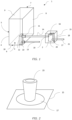
- FIG. 1 schematically presents outdoor unit (1) with a gas-liquid separator (2).
- the figure shows a heat medium circuit comprising a plate heat exchanger (3) having heat medium side and a refrigerant side. On the refrigerant side, said plate heat exchanger (3) is in further contact with a refrigerant circuit (not shown) having a compressor, a heat source heat exchanger, an expansion means.
- the outdoor unit (1) further includes a housing (4) comprising a front plate (5), a first side plate (6), a second side plate (7), a rear plate (8), top plate (9) and a bottom plate (10), the housing (4) accommodating all elements of the refrigerant circuit (not shown) and the plate heat exchanger (3).
- the plate heat exchanger (3) is shown with a first side wall where a first inlet port (12) and a first outlet port (11).
- the first inlet port is shown positioned at a lower part of the plate heat exchanger and the first outlet port is positioned at an upper part of the plate heat exchanger.
- the plate heat exchanger (3) is shown arranged in the outdoor unit (1) so that the first side wall of the plate heat exchanger (3) is adjacent to the inner surface of the rear plate (8).
- a first and a second heat medium connection pipes (13, 14) connects to and extend from respectively the first inlet port (12) and the first outlet port (11), said first and second heat medium connection pipes (13, 14) extending through the rear plate (8).
- the second heat medium connection pipe (14) comprises a substantially straight section at said second inlet port (19). This permits a laminar flow of the heat medium as it enters the gas-liquid separator (2), thereby facilitating the stratification of any leaked refrigerant above said heat medium, thus greatly facilitating further separation and purging of said refrigerant.
- the gas-liquid separator (2) is shown disposed on the heat medium circuit and outside of the housing (4), and is connected to the first outlet port (11) via the second heat medium connection pipe (14).
- the risk of refrigerant leakage increases with the number of connections the piping fluidly connecting the plate heat exchanger (3) with the gas-liquid separator (2).
- the outdoor unit (1) according to the present invention advantageously minimizes the number of said connections, thereby eliminating the risk of refrigerant leakage from the piping before any heat medium reaches the gas-liquid separator (2).
- any refrigerant leaked into the heat medium is advantageously separated in the gas-liquid separator (2) and subsequently discharged in a controlled manner, thus preventing any ingress of refrigerant into any indoor elements of the heat pump system.
- the gas-liquid separator (2) is shown inside a separator housing (15), said separator housing (15) defining a space outside of the housing (4) of the outdoor unit (1).
- the separator housing (15) also provides the gas-liquid separator (2) with protection against damage and the direct influence of weather. This permits a separation performance which is consistent and effective.
- the discharge of the separated refrigerant is essential to avoid pressure buildup inside the separator (2), and for keeping the efficiency of the same at an optimal level, thus better preventing any refrigerant leaked into the heat medium pipes from proceeding to any of the indoor elements of the heat-pump.
- a gas purge valve (16) is shown on the gas-liquid separator (2), the separator housing (15) further comprises an opening (17) to exhaust gas discharged from the gas purge valve (16).
- said opening (17) is shown located at the bottom of the separator housing (15).
- a duct (18) fluidly connects the gas purge valve (16) and the opening (17).
- the gas-liquid separator (2) comprises a second inlet port (19) connected to the second heat medium connection pipe (14), for receiving heat medium, and a second outlet port (20) for evacuating processed heat medium from the gas-liquid separator (2), wherein the second inlet port (19) and the second outlet port (20) are arranged on a lateral face of the gas-liquid separator (2) and on opposite sides with respect to each other.
- the second outlet port (20) is shown arranged at a lower position than the second inlet port (19). The height difference in the placement of the second ports (19, 20) maximizes the distance between said ports, and thus dwell time of the heat medium inside the gas-liquid separator (2).
- the second outlet port (20) is shown further connected to a third heat medium connection pipe (21) which comprises a substantially straight section at the second outlet port (20).
- the first side wall of the plate heat exchanger is positioned within a distance of at most 5.0 cm. In this way, sufficient space is provided inside the outdoor unit (1) for the elements of the refrigerant circuit, in particular a compressor and expansion valve.
- first and/or second heat medium connection pipes (13, 14) comprise flexible tubes. These types of tube allow for a broader spectrum of options regarding the positioning of the gas-liquid separator (2), which permits accommodation of the outdoor unit (1) and the separator (2) in more confined spaces.
- the separator housing (15) is adhered to or positioned parallel to the first side wall (22). In this way, the length of the second heat medium connection pipe (14) is advantageously minimized.
- FIG. 2 presents an embodiment of the opening (17) of the separator housing (15).
- the opening (17) is shown positioned on the top of the separator housing (15).
- This configuration of the separator housing (15) permits direct expulsion of the separated refrigerant from the gas-liquid separator (2).
Landscapes
- Engineering & Computer Science (AREA)
- Mechanical Engineering (AREA)
- General Engineering & Computer Science (AREA)
- Chemical & Material Sciences (AREA)
- Combustion & Propulsion (AREA)
- Physics & Mathematics (AREA)
- Thermal Sciences (AREA)
- Life Sciences & Earth Sciences (AREA)
- Sustainable Development (AREA)
- Other Air-Conditioning Systems (AREA)
Abstract
Description
- The present invention relates to an outdoor unit for a heat pump system.
- In recent years, the use of natural refrigerants has been required to prevent global warming. Refrigerants such as R290 are set to replace previous refrigerants currently being phased out. Such new refrigerants, however, are characterized by a high volatility and flammability, and are likely to cause explosions should they leak and accumulate near sources of ignition. One way a refrigerant may inadvertently be released from a heat pump system is by leaking into heat medium piping, thereby being able to travel along with said medium from the outdoor unit, and into an indoor unit, causing said refrigerant to be released indoor.
- A possible countermeasure consists in the placement of a gas-liquid separator at or near the heat medium output piping of an outdoor unit. These gas-liquid separator are often placed downstream of the outdoor unit. However, when piping having multiple connection points is used in piping connecting the outdoor unit to the gas-liquid separator, there is a risk that refrigerant will leak from the connection points. This leads to the issue that, the more connection points are present, the greater the risk of leakage becomes.
- The present invention aims to resolve at least some of the problems and disadvantages mentioned above.
- The present invention aims to resolve at least some of the problems and disadvantages mentioned above. The invention thereto aims to provide an outdoor unit for a heat pump system using a flammable, combustible and/or explosive refrigerant. According to a first aspect, said outdoor unit comprises:
- a refrigerant circuit having a compressor, a heat source heat exchanger, an expansion means, and a refrigerant side of a plate heat exchanger;
- a heat medium circuit comprising a heat medium side of the plate heat exchanger;
- a housing comprising a front plate, a first side plate, a second side plate, a rear plate, top plate and a bottom plate, and accommodating the compressor, the heat source heat exchanger, an expansion valve and the plate heat exchanger.
- The plate heat exchanger has a first side wall where a first inlet port and a first outlet port are provided, and the plate heat exchanger is arranged in the outdoor unit so that the first side wall of the plate heat exchanger is adjacent to the inner surface of the rear plate, or adjacent to the inner surface of the first side plate. A first and a second heat medium connection pipe connect to and extend from respectively the first inlet port and the first outlet port, said first and second heat medium connection pipes extending through the rear plate or the first side plate. The outdoor unit provides a gas-liquid separator which is disposed on the heat medium circuit and outside of the housing, and is connected to the first outlet port via the second heat medium connection pipe. The risk of refrigerant leakage increases with the number of connections the piping fluidly connecting the heat exchanger with the gas-liquid separator. The outdoor unit according to the present invention advantageously minimizes the number of said connections, thereby eliminating the risk of refrigerant leakage from the piping before any heat medium reaches the gas-liquid separator. In this way, any refrigerant leaked into the heat medium is advantageously separated in the gas-liquid separator and subsequently discharged in a controlled manner, thus preventing any ingress of refrigerant into any indoor elements of the heat pump.
- It should furthermore be noted that the summation of the plates forming the housing does not mean that these plates are necessarily separate plates that are connected to each other. Two or more of the mentioned plates may be single-piece, and can be curved, bent, folded or otherwise shaped to form two or more of the mentioned plates in functional terms, the qualifier terms (front, first side, second side, rear, top, bottom) being meant to denote relative position.
- In this context, the term "gas" is to be understood as the gaseous state of the refrigerant used in the outdoor unit. The term "gas-separator" is used without prejudice to any other substances or combinations thereof which, when in their gaseous state, may also be separated from the heat medium by means of the gas liquid separator.
- Further embodiments of the outdoor unit according to the invention are further described below. These embodiments are disclosed by the
dependent claims 2 to 13. In an embodiment, The outdoor unit further comprises a separator housing accommodating the gas-liquid separator, said separator housing defining a space outside of the housing of the outdoor unit, allowing more control over how, and more precisely where, the refrigerant separated from the heat medium is discharged. In this way, the separated refrigerant leaving the gas-liquid separator is advantageously always released outside of the outdoor unit, away from any sources of ignition within the outdoor unit. The separator housing also provides the gas-liquid separator with protection against damage and the direct influence of weather, thus allowing for a separation performance which is consistently effective. - In an embodiment, the first inlet port is positioned at a lower part of the plate heat exchanger and the first outlet port is positioned at an upper part of the plate heat exchanger. This permits taking advantage of the tendency of the refrigerant to float above the heat medium due to its much lower density. In the event of some refrigerant leaks into the heat medium side of the heat exchanger, said refrigerant is advantageously carried along with the heat medium to the gas-liquid separator, thus promoting both the safety and a more efficient operation of the performance of the plate heat exchanger.
- In an embodiment, wherein a gas purge valve is disposed on the gas-liquid separator, and the separator housing further comprises an opening to exhaust gas discharged from the gas purge valve. By enabling the discharge of the separated refrigerant, first from the gas-liquid separator and then from the housing, pressure buildup inside the separator is advantageously avoided. In this way, the efficiency of the gas-liquid separator is kept at an optimal level, thus better preventing any refrigerant leaked into the heat medium pipes from proceeding to any of the indoor elements of the heat-pump.
- In an embodiment, the opening is positioned on the top of the separator housing. In this way, the distance between the purge valve of the separator and the exhaust opening of the separator housing is kept advantageously short, thereby permitting a more direct release of the separated refrigerant.
- In an embodiment, the opening is positioned on the bottom of the separator housing. In this embodiment, while the path between the purge valve of the separator and the exhaust opening of the separator housing is longer, the lower position of the opening permits taking advantage of the density of the refrigerant being higher than that of air, assuring that the discharged refrigerant cannot re-enter the outdoor unit as it will naturally disperse downward, further away from the outdoor unit.
- In an embodiment, the gas-purge valve comprises an air passage, through which separated gas flows, wherein the air passage protrudes from the opening to the outside of the separator housing. This advantageously permits direct expulsion of the separated refrigerant from the gas-liquid separator.
- In an embodiment, the separator housing further comprises a duct, wherein said duct is connected to the opening, wherein said duct is connected to the gas purge valve, through which duct separated gas flows from the gas purge valve to and out of the opening. In this way, the separated refrigerant is not allowed to dwell inside the separator housing, thereby eliminating the risk of explosion and/or pressure accumulation inside said housing.
- In an embodiment, the gas-liquid separator comprises a second inlet port connected to the second heat medium connection pipe, for receiving heat medium, and a second outlet port for evacuating processed heat medium from the gas-liquid separator, wherein the second inlet port and the second outlet port are arranged on opposite sides of the gas-liquid separator with respect to each other. By preference, the second outlet port is arranged at a lower position than the second inlet port. More preferably, said second outlet is arranged at the bottom of the gas-liquid separator. In this way, the buoyancy of the refrigerant in combination with a longer dwell time of the heat medium inside the gas-liquid separator are advantageously used in order to optimize separation efficiency.
- In this context, the wording "dwell time" is to be understood as the time interval between the moment of ingress of a volume of heat medium into the gas-liquid separator via the second inlet, and the moment said volume leaves said separator via the second outlet. Said dwell time may be increased by, for example though not exclusively, reducing the flow of heat medium by reducing the pump speed, or by increasing the distance between the second inlet and the second outlet of the separator.
- In an embodiment, the gas-liquid separator comprises a second inlet port connected to the second heat medium connection pipe, for receiving heat medium, and a second outlet port for evacuating processed heat medium from the gas-liquid separator, which the a second inlet port and the second outlet port are provided in a lateral face of the gas-liquid separator, wherein the second outlet port is connected to a third heat medium connection pipe which comprises a substantially straight section at said second outlet port.
- In an embodiment, the second heat medium connection pipe comprises a substantially straight section from said second inlet port. This permits a laminar flow of the heat medium as it enters the gas-liquid separator, thereby facilitating the stratification of any leaked refrigerant above said heat medium, thus greatly facilitating further separation and purging of said refrigerant.
- In an embodiment, wherein the first and/or second heat medium connection pipes comprise flexible tubes. These types of tube allow for a broader spectrum of options regarding the positioning of the gas-liquid separator, which permits accommodation of the outdoor unit and the separator in more confined spaces.
- In an embodiment, wherein the first side wall of the plate heat exchanger is positioned within a distance of at most 5.0 cm.
- In an embodiment, the plate heat exchanger is adjacent to the inner surface of the rear plate, and the first and second heat medium connection pipes extend through the rear plate or the first side plate. Distance for the piping to traverse within the outdoor unit is minimized this way, reducing risk of leakage, as well as limiting material cost.
- In a further preferred embodiment, the plate heat exchanger extends substantially parallel to the rear plate. This provides for a particularly advantageous configuration wherein the available volume is optimized.
- The following description of the figures of specific embodiments of the invention is merely exemplary in nature and is not intended to limit the present teachings, their application or uses. Throughout the drawings, corresponding reference numerals indicate like or corresponding parts and features.
-
Figure 1 schematically presents outdoor unit (1) with a gas-liquid separator (2). -
Figure 2 presents an embodiment of the opening (17) of the separator housing (15) - The invention is further described by the following non-limiting examples which further illustrate the invention, and are not intended to, nor should they be interpreted to, limit the scope of the invention.
- The present invention concerns an outdoor unit for a heat pump, said unit is provided with a gas-liquid separator disposed on the heat medium circuit and outside of the housing. The outdoor unit according to the present invention advantageously minimizes the number of piping connections before the heat medium leaving the heat exchanger of the outdoor unit reaches the gas-liquid separator. This eliminates the risk of refrigerant leakage from the piping before any heat medium reaches the gas-liquid separator. In this way, any refrigerant leaked into the heat medium is advantageously separated in the gas-liquid separator and subsequently discharged in a controlled manner, thus preventing any ingress of refrigerant into any indoor elements of the heat pump.
- Unless otherwise defined, all terms used in disclosing the invention, including technical and scientific terms, have the meaning as commonly understood by one of ordinary skill in the art to which this invention belongs. By means of further guidance, term definitions are included to better appreciate the teaching of the present invention.
- As used herein, the following terms have the following meanings:
"A", "an", and "the" as used herein refers to both singular and plural referents unless the context clearly dictates otherwise. By way of example, "a compartment" refers to one or more than one compartment. - "Comprise", "comprising", and "comprises" and "comprised of" as used herein are synonymous with "include", "including", "includes" or "contain", "containing", "contains" and are inclusive or open-ended terms that specifies the presence of what follows e.g. component and do not exclude or preclude the presence of additional, non-recited components, features, element, members, steps, known in the art or disclosed therein.
- Furthermore, the terms first, second, third and the like in the description and in the claims, are used for distinguishing between similar elements and not necessarily for describing a sequential or chronological order, unless specified. It is to be understood that the terms so used are interchangeable under appropriate circumstances and that the embodiments of the invention described herein are capable of operation in other sequences than described or illustrated herein.
- The recitation of numerical ranges by endpoints includes all numbers and fractions subsumed within that range, as well as the recited endpoints.
- Whereas the terms "one or more" or "at least one", such as one or more or at least one member(s) of a group of members, is clear per se, by means of further exemplification, the term encompasses inter alia a reference to any one of said members, or to any two or more of said members, such as, e.g., any ≥3, ≥4, ≥5, ≥6 or ≥7 etc. of said members, and up to all said members.
- Unless otherwise defined, all terms used in disclosing the invention, including technical and scientific terms, have the meaning as commonly understood by one of ordinary skill in the art to which this invention belongs. By means of further guidance, definitions for the terms used in the description are included to better appreciate the teaching of the present invention. The terms or definitions used herein are provided solely to aid in the understanding of the invention.
- Reference throughout this specification to "one embodiment" or "an embodiment" means that a particular feature, structure or characteristic described in connection with the embodiment is included in at least one embodiment of the present invention. Thus, appearances of the phrases "in one embodiment" or "in an embodiment" in various places throughout this specification are not necessarily all referring to the same embodiment, but may. Furthermore, the particular features, structures or characteristics may be combined in any suitable manner, as would be apparent to a person skilled in the art from this disclosure, in one or more embodiments. Furthermore, while some embodiments described herein include some but not other features included in other embodiments, combinations of features of different embodiments are meant to be within the scope of the invention, and form different embodiments, as would be understood by those in the art. For example, in the following claims, any of the claimed embodiments can be used in any combination. With as a goal illustrating better the properties of the invention the following presents, as an example and limiting in no way other potential applications, a description of a number of preferred embodiments of the outdoor unit based on the invention, wherein:
-
FIG. 1 schematically presents outdoor unit (1) with a gas-liquid separator (2). The figure shows a heat medium circuit comprising a plate heat exchanger (3) having heat medium side and a refrigerant side. On the refrigerant side, said plate heat exchanger (3) is in further contact with a refrigerant circuit (not shown) having a compressor, a heat source heat exchanger, an expansion means. The outdoor unit (1) further includes a housing (4) comprising a front plate (5), a first side plate (6), a second side plate (7), a rear plate (8), top plate (9) and a bottom plate (10), the housing (4) accommodating all elements of the refrigerant circuit (not shown) and the plate heat exchanger (3). The plate heat exchanger (3) is shown with a first side wall where a first inlet port (12) and a first outlet port (11). The first inlet port is shown positioned at a lower part of the plate heat exchanger and the first outlet port is positioned at an upper part of the plate heat exchanger. This permits taking advantage of the tendency of the refrigerant to float above the heat medium due to its much lower density, thereby facilitating the transmission of any refrigerant contaminated heat medium to the gas-liquid separator (2). The plate heat exchanger (3) is shown arranged in the outdoor unit (1) so that the first side wall of the plate heat exchanger (3) is adjacent to the inner surface of the rear plate (8). A first and a second heat medium connection pipes (13, 14) connects to and extend from respectively the first inlet port (12) and the first outlet port (11), said first and second heat medium connection pipes (13, 14) extending through the rear plate (8). The second heat medium connection pipe (14) comprises a substantially straight section at said second inlet port (19). This permits a laminar flow of the heat medium as it enters the gas-liquid separator (2), thereby facilitating the stratification of any leaked refrigerant above said heat medium, thus greatly facilitating further separation and purging of said refrigerant. The gas-liquid separator (2) is shown disposed on the heat medium circuit and outside of the housing (4), and is connected to the first outlet port (11) via the second heat medium connection pipe (14). The risk of refrigerant leakage increases with the number of connections the piping fluidly connecting the plate heat exchanger (3) with the gas-liquid separator (2). The outdoor unit (1) according to the present invention advantageously minimizes the number of said connections, thereby eliminating the risk of refrigerant leakage from the piping before any heat medium reaches the gas-liquid separator (2). In this way, any refrigerant leaked into the heat medium is advantageously separated in the gas-liquid separator (2) and subsequently discharged in a controlled manner, thus preventing any ingress of refrigerant into any indoor elements of the heat pump system. The gas-liquid separator (2) is shown inside a separator housing (15), said separator housing (15) defining a space outside of the housing (4) of the outdoor unit (1). In this way, the separated refrigerant is always released outside of the outdoor unit (1) while using no extra piping, thus simplifying the construction of the outdoor unit (1). The separator housing (15) also provides the gas-liquid separator (2) with protection against damage and the direct influence of weather. This permits a separation performance which is consistent and effective. The discharge of the separated refrigerant is essential to avoid pressure buildup inside the separator (2), and for keeping the efficiency of the same at an optimal level, thus better preventing any refrigerant leaked into the heat medium pipes from proceeding to any of the indoor elements of the heat-pump. A gas purge valve (16) is shown on the gas-liquid separator (2), the separator housing (15) further comprises an opening (17) to exhaust gas discharged from the gas purge valve (16). In this embodiment, said opening (17) is shown located at the bottom of the separator housing (15). A duct (18) fluidly connects the gas purge valve (16) and the opening (17). By providing a duct (18) inside the separator housing (15), refrigerant does not pool or dwell inside the separator housing (15) of the gas-liquid separator (2), thereby eliminating the risk of explosion and/or pressure accumulation inside said separator housing (15). By discharging the refrigerant under and away from the outdoor unit (1), the risk of the refrigerant coming into contact with any of the other elements of the outdoor unit (1), in particular those which may act as a source of ignition and deflagrate the refrigerant is advantageously avoided, thus precluding the occurrence of a fire and/or explosion. The gas-liquid separator (2) comprises a second inlet port (19) connected to the second heat medium connection pipe (14), for receiving heat medium, and a second outlet port (20) for evacuating processed heat medium from the gas-liquid separator (2), wherein the second inlet port (19) and the second outlet port (20) are arranged on a lateral face of the gas-liquid separator (2) and on opposite sides with respect to each other. The second outlet port (20) is shown arranged at a lower position than the second inlet port (19). The height difference in the placement of the second ports (19, 20) maximizes the distance between said ports, and thus dwell time of the heat medium inside the gas-liquid separator (2). In this way, any leaked refrigerant will, by virtue of its higher buoyancy, have more time to rise to the top portion of the separator (2), and in this way optimizing separation efficiency. The second outlet port (20) is shown further connected to a third heat medium connection pipe (21) which comprises a substantially straight section at the second outlet port (20). - In an embodiment, wherein the first side wall of the plate heat exchanger is positioned within a distance of at most 5.0 cm. In this way, sufficient space is provided inside the outdoor unit (1) for the elements of the refrigerant circuit, in particular a compressor and expansion valve.
- In an embodiment, wherein the first and/or second heat medium connection pipes (13, 14) comprise flexible tubes. These types of tube allow for a broader spectrum of options regarding the positioning of the gas-liquid separator (2), which permits accommodation of the outdoor unit (1) and the separator (2) in more confined spaces.
- In an embodiment, the separator housing (15) is adhered to or positioned parallel to the first side wall (22). In this way, the length of the second heat medium connection pipe (14) is advantageously minimized.
-
FIG. 2 presents an embodiment of the opening (17) of the separator housing (15). The opening (17) is shown positioned on the top of the separator housing (15). An air passage (23) extending from the gas-purge valve (16 not shown) on top of the gas-liquid separator (2), which is not shown in this Figure, is shown extending beyond the opening (17). This configuration of the separator housing (15) permits direct expulsion of the separated refrigerant from the gas-liquid separator (2). - The present invention is in no way limited to the embodiments described in the examples and/or shown in the figures. On the contrary, methods according to the present invention may be realized in many different ways without departing from the scope of the invention.
-
- 1
- outdoor unit
- 2
- gas-liquid separator
- 3
- plate heat exchanger
- 4
- housing
- 5
- front plate
- 6
- first side plate
- 7
- second side plate
- 8
- rear plate
- 9
- top plate
- 10
- bottom plate
- 11
- first outlet port
- 12
- first inlet port
- 13
- first heat medium connection pipe
- 14
- second heat medium connection pipe
- 15
- separator housing
- 16
- gas purge valve
- 17
- opening
- 18
- duct
- 19
- second inlet port
- 20
- second outlet port
- 21
- third heat medium connection pipe
- 22
- first side wall
- 23
- air passage
Claims (13)
- An outdoor unit for a heat pump system using a flammable, combustible and/or explosive refrigerant comprising:a refrigerant circuit having a compressor, a heat source heat exchanger, an expansion means, and a refrigerant side of a plate heat exchanger;a heat medium circuit comprising a heat medium side of the plate heat exchanger;a housing comprising a front plate, a first side plate, a second side plate, a rear plate, top plate and a bottom plate, and accommodating the compressor, the heat source heat exchanger, an expansion valve and the plate heat exchanger;wherein the plate heat exchanger has a first side wall where a first inlet port and a first outlet port are provided, and the plate heat exchanger is arranged in the outdoor unit so that the first side wall of the plate heat exchanger is adjacent to the inner surface of the rear plate, or adjacent to the inner surface of the first side plate, wherein a first and a second heat medium connection pipe connect to and extend from respectively the first inlet port and the first outlet port, said first and second heat medium connection pipes extending through the rear plate or the first side plate, andwherein the outdoor unit provides a gas-liquid separator, and the gas-liquid separator is disposed on the heat medium circuit and outside of the housing, and is connected to the first outlet port via the second heat medium connection pipe.
- The outdoor unit for a heat pump system according to the claim 1, further comprises a separator housing accommodating the gas-liquid separator, said separator housing defining a space outside of the housing of the outdoor unit.
- The outdoor unit for a heat pump system according to the claim 2, the first inlet port is positioned at a lower part of the plate heat exchanger and the first outlet port is positioned at an upper part of the plate heat exchanger.
- The outdoor unit for a heat pump system according to any one of the claims 1 to 3, wherein a gas purge valve is disposed on the gas-liquid separator, and the separator housing further comprises an opening to exhaust gas discharged from the gas purge valve.
- The outdoor unit for a heat pump system according to claim 4, the opening is positioned on the top of the separator housing.
- The outdoor unit for a heat pump system according to claim 4, the opening is positioned on the bottom of the separator housing.
- The outdoor unit for a heat pump system according to any one of the preceding claims 4 to 6, the gas-purge valve comprises an air passage, through which separated gas flows, wherein the air passage protrudes from the opening to the outside of the separator housing.
- The outdoor unit for a heat pump system according to the claim 6, the separator housing further comprises a duct, wherein said duct is connected to the opening, wherein said duct is connected to the gas purge valve, through which duct separated gas flows from the gas purge valve to and out of the opening.
- The outdoor unit for a heat pump system according to any one of the claims 1 to 8, the gas-liquid separator comprises a second inlet port connected to the second heat medium connection pipe, for receiving heat medium, and a second outlet port for evacuating processed heat medium from the gas-liquid separator, wherein the second inlet port and the second outlet port are arranged on opposite sides of the gas-liquid separator with respect to each other.
- The outdoor unit for a heat pump system according to any one of the claims 1 to 8, the gas-liquid separator comprises a second inlet port connected to the second heat medium connection pipe, for receiving heat medium, and a second outlet port for evacuating processed heat medium from the gas-liquid separator, which the a second inlet port and the second outlet port are provided in a lateral face of the gas-liquid separator, wherein the second outlet port is connected to a third heat medium connection pipe which comprises a substantially straight section at said second outlet port.
- The outdoor unit for a heat pump system according to claim 10, wherein the second heat medium connection pipe comprises a substantially straight section at said second inlet port.
- The outdoor unit for a heat pump system according to any one of the claims 1 to 11, wherein the first and/or second heat medium connection pipes comprise flexible tubes.
- The outdoor unit for a heat pump system according to any one of the claims 1 to 12, wherein the first side wall of the plate heat exchanger is positioned within a distance of at most 5.0 cm.
Priority Applications (1)
| Application Number | Priority Date | Filing Date | Title |
|---|---|---|---|
| EP23211294.6A EP4560205A1 (en) | 2023-11-21 | 2023-11-21 | Outdoor unit for a heat pump system |
Applications Claiming Priority (1)
| Application Number | Priority Date | Filing Date | Title |
|---|---|---|---|
| EP23211294.6A EP4560205A1 (en) | 2023-11-21 | 2023-11-21 | Outdoor unit for a heat pump system |
Publications (1)
| Publication Number | Publication Date |
|---|---|
| EP4560205A1 true EP4560205A1 (en) | 2025-05-28 |
Family
ID=88920788
Family Applications (1)
| Application Number | Title | Priority Date | Filing Date |
|---|---|---|---|
| EP23211294.6A Pending EP4560205A1 (en) | 2023-11-21 | 2023-11-21 | Outdoor unit for a heat pump system |
Country Status (1)
| Country | Link |
|---|---|
| EP (1) | EP4560205A1 (en) |
Citations (4)
| Publication number | Priority date | Publication date | Assignee | Title |
|---|---|---|---|---|
| CN1239854C (en) * | 2002-08-22 | 2006-02-01 | Lg电子株式会社 | Multimachine air conditioner and operating method for controlling outdoor machine fan |
| US20190186773A1 (en) * | 2016-08-23 | 2019-06-20 | Gd Midea Heating & Ventilating Equipment Co., Ltd. | Switching device for multi-split air conditioner and multi-split air conditioner having same |
| CN214283041U (en) * | 2020-12-21 | 2021-09-28 | 广州市赛思达机械设备有限公司 | Energy-saving heat pump type proofing and chilled water combined machine |
| JP2022126030A (en) * | 2021-02-18 | 2022-08-30 | パナソニックIpマネジメント株式会社 | Heat medium circulation system |
-
2023
- 2023-11-21 EP EP23211294.6A patent/EP4560205A1/en active Pending
Patent Citations (4)
| Publication number | Priority date | Publication date | Assignee | Title |
|---|---|---|---|---|
| CN1239854C (en) * | 2002-08-22 | 2006-02-01 | Lg电子株式会社 | Multimachine air conditioner and operating method for controlling outdoor machine fan |
| US20190186773A1 (en) * | 2016-08-23 | 2019-06-20 | Gd Midea Heating & Ventilating Equipment Co., Ltd. | Switching device for multi-split air conditioner and multi-split air conditioner having same |
| CN214283041U (en) * | 2020-12-21 | 2021-09-28 | 广州市赛思达机械设备有限公司 | Energy-saving heat pump type proofing and chilled water combined machine |
| JP2022126030A (en) * | 2021-02-18 | 2022-08-30 | パナソニックIpマネジメント株式会社 | Heat medium circulation system |
Similar Documents
| Publication | Publication Date | Title |
|---|---|---|
| CN100387907C (en) | Air conditioning apparatus | |
| EP2674699B1 (en) | Gas liquid separator and refrigeration cycle device | |
| CN102242992B (en) | Refrigerant vapor-liquid separation and liquid storage integration device and air conditioning system using the device | |
| EP4047288A1 (en) | Heat medium circulation system | |
| EP2778569B1 (en) | Air conditioner | |
| EP4345402A1 (en) | Heat pump cycle device | |
| EP2801770B1 (en) | Refrigeration device | |
| CN110542251A (en) | Improved gas-liquid separator | |
| EP4345381A1 (en) | Heat pump cycle device | |
| CN106556191A (en) | Ship refrigerating plant | |
| US11175078B2 (en) | Gas-liquid separator and air conditioner including the same | |
| JP2008175432A (en) | Refrigeration cycle equipment | |
| EP1693632A2 (en) | Service valve assembly and air conditioner having the same | |
| EP3695175B1 (en) | Refrigerating cycle apparatus | |
| CN113945032B (en) | Vertical liquid receiver and refrigerating system with same | |
| CN109186053B (en) | Heat recovery device and air conditioner | |
| CN112781128B (en) | Air conditioning system and control method thereof | |
| CN105298797A (en) | Liquid impact preventing device for compressor, control method of liquid impact preventing device and refrigeration air conditioner | |
| EP4560206A1 (en) | Outdoor unit for a heat pump system | |
| CN208887042U (en) | heat recovery device and air conditioner | |
| EP4560208A1 (en) | Outdoor unit for a heat pump system | |
| US12123602B2 (en) | Air-conditioner with fluid tank | |
| EP4553399B1 (en) | Utilization unit and refrigeration device | |
| CN111927793B (en) | Centrifugal compressor balance pipe assembly, centrifugal compressor and refrigerating system | |
| EP4682445A1 (en) | Release device unit and a heat pump system comprising a release device |
Legal Events
| Date | Code | Title | Description |
|---|---|---|---|
| PUAI | Public reference made under article 153(3) epc to a published international application that has entered the european phase |
Free format text: ORIGINAL CODE: 0009012 |
|
| STAA | Information on the status of an ep patent application or granted ep patent |
Free format text: STATUS: THE APPLICATION HAS BEEN PUBLISHED |
|
| AK | Designated contracting states |
Kind code of ref document: A1 Designated state(s): AL AT BE BG CH CY CZ DE DK EE ES FI FR GB GR HR HU IE IS IT LI LT LU LV MC ME MK MT NL NO PL PT RO RS SE SI SK SM TR |
|
| STAA | Information on the status of an ep patent application or granted ep patent |
Free format text: STATUS: REQUEST FOR EXAMINATION WAS MADE |
|
| 17P | Request for examination filed |
Effective date: 20250611 |
|
| GRAP | Despatch of communication of intention to grant a patent |
Free format text: ORIGINAL CODE: EPIDOSNIGR1 |
|
| STAA | Information on the status of an ep patent application or granted ep patent |
Free format text: STATUS: GRANT OF PATENT IS INTENDED |