EP4560164A1 - Traveling device of work vehicle - Google Patents
Traveling device of work vehicle Download PDFInfo
- Publication number
- EP4560164A1 EP4560164A1 EP23871484.4A EP23871484A EP4560164A1 EP 4560164 A1 EP4560164 A1 EP 4560164A1 EP 23871484 A EP23871484 A EP 23871484A EP 4560164 A1 EP4560164 A1 EP 4560164A1
- Authority
- EP
- European Patent Office
- Prior art keywords
- coupling
- oil
- oil passage
- housing
- rotation shaft
- Prior art date
- Legal status (The legal status is an assumption and is not a legal conclusion. Google has not performed a legal analysis and makes no representation as to the accuracy of the status listed.)
- Pending
Links
Images



Classifications
-
- H—ELECTRICITY
- H02—GENERATION; CONVERSION OR DISTRIBUTION OF ELECTRIC POWER
- H02K—DYNAMO-ELECTRIC MACHINES
- H02K7/00—Arrangements for handling mechanical energy structurally associated with dynamo-electric machines, e.g. structural association with mechanical driving motors or auxiliary dynamo-electric machines
- H02K7/003—Couplings; Details of shafts
-
- B—PERFORMING OPERATIONS; TRANSPORTING
- B60—VEHICLES IN GENERAL
- B60K—ARRANGEMENT OR MOUNTING OF PROPULSION UNITS OR OF TRANSMISSIONS IN VEHICLES; ARRANGEMENT OR MOUNTING OF PLURAL DIVERSE PRIME-MOVERS IN VEHICLES; AUXILIARY DRIVES FOR VEHICLES; INSTRUMENTATION OR DASHBOARDS FOR VEHICLES; ARRANGEMENTS IN CONNECTION WITH COOLING, AIR INTAKE, GAS EXHAUST OR FUEL SUPPLY OF PROPULSION UNITS IN VEHICLES
- B60K17/00—Arrangement or mounting of transmissions in vehicles
- B60K17/04—Arrangement or mounting of transmissions in vehicles characterised by arrangement, location or kind of gearing
- B60K17/043—Transmission unit disposed in on near the vehicle wheel, or between the differential gear unit and the wheel
- B60K17/046—Transmission unit disposed in on near the vehicle wheel, or between the differential gear unit and the wheel with planetary gearing having orbital motion
-
- B—PERFORMING OPERATIONS; TRANSPORTING
- B60—VEHICLES IN GENERAL
- B60K—ARRANGEMENT OR MOUNTING OF PROPULSION UNITS OR OF TRANSMISSIONS IN VEHICLES; ARRANGEMENT OR MOUNTING OF PLURAL DIVERSE PRIME-MOVERS IN VEHICLES; AUXILIARY DRIVES FOR VEHICLES; INSTRUMENTATION OR DASHBOARDS FOR VEHICLES; ARRANGEMENTS IN CONNECTION WITH COOLING, AIR INTAKE, GAS EXHAUST OR FUEL SUPPLY OF PROPULSION UNITS IN VEHICLES
- B60K7/00—Disposition of motor in, or adjacent to, traction wheel
- B60K7/0007—Disposition of motor in, or adjacent to, traction wheel the motor being electric
-
- B—PERFORMING OPERATIONS; TRANSPORTING
- B60—VEHICLES IN GENERAL
- B60L—PROPULSION OF ELECTRICALLY-PROPELLED VEHICLES; SUPPLYING ELECTRIC POWER FOR AUXILIARY EQUIPMENT OF ELECTRICALLY-PROPELLED VEHICLES; ELECTRODYNAMIC BRAKE SYSTEMS FOR VEHICLES IN GENERAL; MAGNETIC SUSPENSION OR LEVITATION FOR VEHICLES; MONITORING OPERATING VARIABLES OF ELECTRICALLY-PROPELLED VEHICLES; ELECTRIC SAFETY DEVICES FOR ELECTRICALLY-PROPELLED VEHICLES
- B60L50/00—Electric propulsion with power supplied within the vehicle
- B60L50/50—Electric propulsion with power supplied within the vehicle using propulsion power supplied by batteries or fuel cells
-
- B—PERFORMING OPERATIONS; TRANSPORTING
- B60—VEHICLES IN GENERAL
- B60T—VEHICLE BRAKE CONTROL SYSTEMS OR PARTS THEREOF; BRAKE CONTROL SYSTEMS OR PARTS THEREOF, IN GENERAL; ARRANGEMENT OF BRAKING ELEMENTS ON VEHICLES IN GENERAL; PORTABLE DEVICES FOR PREVENTING UNWANTED MOVEMENT OF VEHICLES; VEHICLE MODIFICATIONS TO FACILITATE COOLING OF BRAKES
- B60T1/00—Arrangements of braking elements, i.e. of those parts where braking effect occurs specially for vehicles
- B60T1/02—Arrangements of braking elements, i.e. of those parts where braking effect occurs specially for vehicles acting by retarding wheels
- B60T1/06—Arrangements of braking elements, i.e. of those parts where braking effect occurs specially for vehicles acting by retarding wheels acting otherwise than on tread, e.g. employing rim, drum, disc, or transmission or on double wheels
- B60T1/062—Arrangements of braking elements, i.e. of those parts where braking effect occurs specially for vehicles acting by retarding wheels acting otherwise than on tread, e.g. employing rim, drum, disc, or transmission or on double wheels acting on transmission parts
-
- F—MECHANICAL ENGINEERING; LIGHTING; HEATING; WEAPONS; BLASTING
- F16—ENGINEERING ELEMENTS AND UNITS; GENERAL MEASURES FOR PRODUCING AND MAINTAINING EFFECTIVE FUNCTIONING OF MACHINES OR INSTALLATIONS; THERMAL INSULATION IN GENERAL
- F16H—GEARING
- F16H57/00—General details of gearing
- F16H57/04—Features relating to lubrication or cooling or heating
- F16H57/0412—Cooling or heating; Control of temperature
- F16H57/0415—Air cooling or ventilation; Heat exchangers; Thermal insulations
- F16H57/0417—Heat exchangers adapted or integrated in the gearing
-
- F—MECHANICAL ENGINEERING; LIGHTING; HEATING; WEAPONS; BLASTING
- F16—ENGINEERING ELEMENTS AND UNITS; GENERAL MEASURES FOR PRODUCING AND MAINTAINING EFFECTIVE FUNCTIONING OF MACHINES OR INSTALLATIONS; THERMAL INSULATION IN GENERAL
- F16H—GEARING
- F16H57/00—General details of gearing
- F16H57/04—Features relating to lubrication or cooling or heating
- F16H57/042—Guidance of lubricant
- F16H57/0421—Guidance of lubricant on or within the casing, e.g. shields or baffles for collecting lubricant, tubes, pipes, grooves, channels or the like
- F16H57/0423—Lubricant guiding means mounted or supported on the casing, e.g. shields or baffles for collecting lubricant, tubes or pipes
-
- F—MECHANICAL ENGINEERING; LIGHTING; HEATING; WEAPONS; BLASTING
- F16—ENGINEERING ELEMENTS AND UNITS; GENERAL MEASURES FOR PRODUCING AND MAINTAINING EFFECTIVE FUNCTIONING OF MACHINES OR INSTALLATIONS; THERMAL INSULATION IN GENERAL
- F16H—GEARING
- F16H57/00—General details of gearing
- F16H57/04—Features relating to lubrication or cooling or heating
- F16H57/042—Guidance of lubricant
- F16H57/0421—Guidance of lubricant on or within the casing, e.g. shields or baffles for collecting lubricant, tubes, pipes, grooves, channels or the like
- F16H57/0426—Means for guiding lubricant into an axial channel of a shaft
-
- F—MECHANICAL ENGINEERING; LIGHTING; HEATING; WEAPONS; BLASTING
- F16—ENGINEERING ELEMENTS AND UNITS; GENERAL MEASURES FOR PRODUCING AND MAINTAINING EFFECTIVE FUNCTIONING OF MACHINES OR INSTALLATIONS; THERMAL INSULATION IN GENERAL
- F16H—GEARING
- F16H57/00—General details of gearing
- F16H57/04—Features relating to lubrication or cooling or heating
- F16H57/042—Guidance of lubricant
- F16H57/043—Guidance of lubricant within rotary parts, e.g. axial channels or radial openings in shafts
-
- F—MECHANICAL ENGINEERING; LIGHTING; HEATING; WEAPONS; BLASTING
- F16—ENGINEERING ELEMENTS AND UNITS; GENERAL MEASURES FOR PRODUCING AND MAINTAINING EFFECTIVE FUNCTIONING OF MACHINES OR INSTALLATIONS; THERMAL INSULATION IN GENERAL
- F16H—GEARING
- F16H57/00—General details of gearing
- F16H57/04—Features relating to lubrication or cooling or heating
- F16H57/0434—Features relating to lubrication or cooling or heating relating to lubrication supply, e.g. pumps; Pressure control
- F16H57/0441—Arrangements of pumps
-
- F—MECHANICAL ENGINEERING; LIGHTING; HEATING; WEAPONS; BLASTING
- F16—ENGINEERING ELEMENTS AND UNITS; GENERAL MEASURES FOR PRODUCING AND MAINTAINING EFFECTIVE FUNCTIONING OF MACHINES OR INSTALLATIONS; THERMAL INSULATION IN GENERAL
- F16H—GEARING
- F16H57/00—General details of gearing
- F16H57/04—Features relating to lubrication or cooling or heating
- F16H57/045—Lubricant storage reservoirs, e.g. reservoirs in addition to a gear sump for collecting lubricant in the upper part of a gear case
-
- F—MECHANICAL ENGINEERING; LIGHTING; HEATING; WEAPONS; BLASTING
- F16—ENGINEERING ELEMENTS AND UNITS; GENERAL MEASURES FOR PRODUCING AND MAINTAINING EFFECTIVE FUNCTIONING OF MACHINES OR INSTALLATIONS; THERMAL INSULATION IN GENERAL
- F16H—GEARING
- F16H57/00—General details of gearing
- F16H57/04—Features relating to lubrication or cooling or heating
- F16H57/0457—Splash lubrication
-
- F—MECHANICAL ENGINEERING; LIGHTING; HEATING; WEAPONS; BLASTING
- F16—ENGINEERING ELEMENTS AND UNITS; GENERAL MEASURES FOR PRODUCING AND MAINTAINING EFFECTIVE FUNCTIONING OF MACHINES OR INSTALLATIONS; THERMAL INSULATION IN GENERAL
- F16H—GEARING
- F16H57/00—General details of gearing
- F16H57/04—Features relating to lubrication or cooling or heating
- F16H57/0467—Elements of gearings to be lubricated, cooled or heated
- F16H57/0469—Bearings or seals
- F16H57/0471—Bearing
-
- F—MECHANICAL ENGINEERING; LIGHTING; HEATING; WEAPONS; BLASTING
- F16—ENGINEERING ELEMENTS AND UNITS; GENERAL MEASURES FOR PRODUCING AND MAINTAINING EFFECTIVE FUNCTIONING OF MACHINES OR INSTALLATIONS; THERMAL INSULATION IN GENERAL
- F16H—GEARING
- F16H57/00—General details of gearing
- F16H57/04—Features relating to lubrication or cooling or heating
- F16H57/048—Type of gearings to be lubricated, cooled or heated
- F16H57/0482—Gearings with gears having orbital motion
- F16H57/0486—Gearings with gears having orbital motion with fixed gear ratio
-
- B—PERFORMING OPERATIONS; TRANSPORTING
- B60—VEHICLES IN GENERAL
- B60K—ARRANGEMENT OR MOUNTING OF PROPULSION UNITS OR OF TRANSMISSIONS IN VEHICLES; ARRANGEMENT OR MOUNTING OF PLURAL DIVERSE PRIME-MOVERS IN VEHICLES; AUXILIARY DRIVES FOR VEHICLES; INSTRUMENTATION OR DASHBOARDS FOR VEHICLES; ARRANGEMENTS IN CONNECTION WITH COOLING, AIR INTAKE, GAS EXHAUST OR FUEL SUPPLY OF PROPULSION UNITS IN VEHICLES
- B60K7/00—Disposition of motor in, or adjacent to, traction wheel
- B60K2007/0038—Disposition of motor in, or adjacent to, traction wheel the motor moving together with the wheel axle
-
- B—PERFORMING OPERATIONS; TRANSPORTING
- B60—VEHICLES IN GENERAL
- B60K—ARRANGEMENT OR MOUNTING OF PROPULSION UNITS OR OF TRANSMISSIONS IN VEHICLES; ARRANGEMENT OR MOUNTING OF PLURAL DIVERSE PRIME-MOVERS IN VEHICLES; AUXILIARY DRIVES FOR VEHICLES; INSTRUMENTATION OR DASHBOARDS FOR VEHICLES; ARRANGEMENTS IN CONNECTION WITH COOLING, AIR INTAKE, GAS EXHAUST OR FUEL SUPPLY OF PROPULSION UNITS IN VEHICLES
- B60K7/00—Disposition of motor in, or adjacent to, traction wheel
- B60K2007/0092—Disposition of motor in, or adjacent to, traction wheel the motor axle being coaxial to the wheel axle
-
- B—PERFORMING OPERATIONS; TRANSPORTING
- B60—VEHICLES IN GENERAL
- B60Y—INDEXING SCHEME RELATING TO ASPECTS CROSS-CUTTING VEHICLE TECHNOLOGY
- B60Y2200/00—Type of vehicle
- B60Y2200/10—Road Vehicles
- B60Y2200/14—Trucks; Load vehicles, Busses
- B60Y2200/142—Heavy duty trucks
-
- B—PERFORMING OPERATIONS; TRANSPORTING
- B60—VEHICLES IN GENERAL
- B60Y—INDEXING SCHEME RELATING TO ASPECTS CROSS-CUTTING VEHICLE TECHNOLOGY
- B60Y2200/00—Type of vehicle
- B60Y2200/90—Vehicles comprising electric prime movers
-
- F—MECHANICAL ENGINEERING; LIGHTING; HEATING; WEAPONS; BLASTING
- F16—ENGINEERING ELEMENTS AND UNITS; GENERAL MEASURES FOR PRODUCING AND MAINTAINING EFFECTIVE FUNCTIONING OF MACHINES OR INSTALLATIONS; THERMAL INSULATION IN GENERAL
- F16D—COUPLINGS FOR TRANSMITTING ROTATION; CLUTCHES; BRAKES
- F16D55/00—Brakes with substantially-radial braking surfaces pressed together in axial direction, e.g. disc brakes
- F16D2055/0004—Parts or details of disc brakes
- F16D2055/0033—Fully-enclosing housings
-
- F—MECHANICAL ENGINEERING; LIGHTING; HEATING; WEAPONS; BLASTING
- F16—ENGINEERING ELEMENTS AND UNITS; GENERAL MEASURES FOR PRODUCING AND MAINTAINING EFFECTIVE FUNCTIONING OF MACHINES OR INSTALLATIONS; THERMAL INSULATION IN GENERAL
- F16D—COUPLINGS FOR TRANSMITTING ROTATION; CLUTCHES; BRAKES
- F16D65/00—Parts or details
- F16D65/78—Features relating to cooling
- F16D65/84—Features relating to cooling for disc brakes
- F16D65/853—Features relating to cooling for disc brakes with closed cooling system
-
- F—MECHANICAL ENGINEERING; LIGHTING; HEATING; WEAPONS; BLASTING
- F16—ENGINEERING ELEMENTS AND UNITS; GENERAL MEASURES FOR PRODUCING AND MAINTAINING EFFECTIVE FUNCTIONING OF MACHINES OR INSTALLATIONS; THERMAL INSULATION IN GENERAL
- F16H—GEARING
- F16H1/00—Toothed gearings for conveying rotary motion
- F16H1/28—Toothed gearings for conveying rotary motion with gears having orbital motion
- F16H1/46—Systems consisting of a plurality of gear trains each with orbital gears, i.e. systems having three or more central gears
Definitions
- the vessel 3 is formed as a large-sized container for loading heavy baggage such as crushed stones.
- a rear-side bottom part of the vessel 3 is coupled to a rear end side of the vehicle body 2 through a coupling pin 4 or the like to be capable of lifting and tilting (inclination-rotating).
- a protector 3A is integrally provided on a front-side upper part of the vessel 3 in such a manner as to cover the cab 5 from the upper side.
- the cab 5 is provided in the front part of the vehicle body 2 to be positioned under the protector 3A.
- the cab 5 forms an operator's room.
- An operator's seat, a handle for steering, a plurality of control levers (none of them are shown) and the like are arranged inside the cab 5.
- the rotation shaft 15 is provided on an inner peripheral side of the spindle 12 to axially extend therein.
- the rotation shaft 15 is formed by a single elongated bar-shaped body.
- a rotation shaft spline portion 15A is formed on an outer peripheral surface of one end side of the rotation shaft 15 (electric motor 13-side), and the rotation shaft spline portion 15A is engaged to a rotation shaft-side hole spline portion 40 of the after-mentioned coupling 38.
- the rotation shaft 15 is jointed via the coupling 38 to the motor shaft 14 of the electric motor 13 and is driven and rotated by the electric motor 13.
- the other end side of the rotation shaft 15 projects out of the open end of the small-diameter cylindrical part 12C of the spindle 12.
- An after-mentioned sun gear 23 is attached to the other end (projection end) of the rotation shaft 15.
- the axial intermediate part of the rotation shaft 15 is rotatably supported by the bearing 16 attached on the inner-side projection part 12G of the spind
- An after-mentioned internal gear 32 and an outer drum 19 are fixed integrally to an end part of the extension cylindrical part 17B of the wheel attaching cylinder 17 by using elongated bolts 20.
- the outer drum 19 is composed of a cylindrical body, and a flange part 19A provided on an axial one side of the outer drum 19.
- the outer drum 19 is fixed via the internal gear 32 to the wheel attaching cylinder 17, and an axial other side of the outer drum 19 is formed as an open end.
- the gear reduction mechanism 21 is provided between the rotation shaft 15 and the wheel attaching cylinder 17.
- the gear reduction mechanism 21 is configured by a first-stage planetary gear reduction mechanism 22 and a second-stage planetary gear reduction mechanism 29.
- the gear reduction mechanism 21 decelerates the rotation of the rotation shaft 15 by two stages, which is transmitted to the wheel attaching cylinder 17.
- the cylindrical projection part 33A of the carrier 33 is spline-coupled to the small-diameter cylindrical part 12C of the spindle 12. Therefore, the revolving movement of the planetary gear 31 (rotation of the carrier 33) is restrained.
- the second-stage planetary gear reduction mechanism 29 converts the rotation of the sun gear 30 into a rotating movement of the planetary gear 31 and transmits the rotating movement of the planetary gear 31 to the second-stage internal gear 32.
- lubricating oil L is stored in the inside of the wheel attaching cylinder 17, and a liquid surface of the lubricating oil L is in a position lower than the lowest part of the small-diameter cylindrical part 12C configuring part of the spindle 12, for example. Therefore, a lower part of the roller bearing 18 is immersed in the lubricating oil L and part of the planetary gear reduction mechanisms 22, 29 is always lubricated by the lubricating oil L. In addition, the lubricating oil L splashed by the planetary gear reduction mechanisms 22, 29 scatters in a mist shape in the spindle 12, which is supplied also to the bearing 16 supporting the rotation shaft 15. As a result, at the operating of the traveling device 11, the resistance against the stirring of the lubricating oil L is made small, making it possible to suppress the energy loss and heat generation of the traveling device 11.
- the wet type brake 35 is attached to the flange part 12F of the spindle 12.
- the wet type brake 35 is configured of a wet multi-plate type of hydraulic brake and applies braking forces to a brake hub 36 attached to the wheel attaching cylinder 17. With this configuration, braking forces are applied to the rotation of the wheel attaching cylinder 17, that is, the rotation of the rear wheel 7.
- a stopper fitting portion 41 is formed on an inner peripheral surface of an axial intermediate part of the coupling 38 to be positioned between the motor shaft-side hole spline portion 39 and the rotation shaft-side hole spline portion 40.
- a portion, which is adjacent to the motor shaft-side hole spline portion 39, of the stopper fitting portion 41 serves as an annular oil passage 41A having an inner diameter dimension larger than the stopper fitting portion 41, and an after-mentioned coupling oil passage 43 opens to the annular oil passage 41A.
- a sleeve fitting portion 38B is provided on an end surface of an axial one side of the coupling 38.
- An after-mentioned sleeve 45 is fitted in the sleeve fitting portion 38B.
- An annular groove 38C is formed over an entire periphery on an inner peripheral surface of the coupling 38 in which the motor shaft-side hole spline portion 39 is formed.
- a C-letter type of a stop ring 42 for hole is attached to the annular groove 38C. As shown in Fig.
- an outer diameter dimension of the stop ring 42 for hole attached to the annular groove 38C is set to be smaller than the tooth tip circle diameter D2 of the motor shaft spline portion 14A spline-coupled to the motor shaft-side hole spline portion 39. Therefore, the gap 38A formed between the tooth bottom of the motor shaft-side hole spline portion 39 and the tooth tip of the motor shaft spline portion 14A is not closed by the stop ring 42 for hole.
- the coupling oil passage 43 is provided in the axial intermediate part of the coupling 38.
- the coupling oil passage 43 supplies the lubricating oil L to the spline coupling portion 39A between the motor shaft 14 (the motor shaft spline portion 14A) and the coupling 38 (the motor shaft-side hole spline portion 39) and to the spline coupling portion 40A between the rotation shaft 15 (the rotation shaft spline portion 15A) and the coupling 38 (the rotation shaft-side hole spline portion 40).
- the coupling oil passage 43 is formed by a plurality of oil passages radially extending by equal angular intervals from the center of the coupling 38.
- the coupling oil passage 43 penetrates from the annular oil passage 41A of the stopper fitting portion 41 through the outer peripheral surface of the coupling 38. With this configuration, the coupling oil passage 43 opens to (is communicated with) an after-mentioned oil reservoir portion 50.
- a portion, which opens to the after-mentioned oil reservoir portion 50, of the coupling oil passage 43 is formed as a tapered large-diameter open end 43A having a diameter larger than the coupling oil passage 43 (Refer to Fig. 10 ).
- a stopper 44 is removably attached to the projection end 14B-side of the motor shaft 14 by using a stopper bolt 44A.
- the stopper 44 is formed in a stepped cylindrical shape as a whole and is provided with a small-diameter fitting portion 44B and a large-diameter fitting portion 44C.
- the small-diameter fitting portion 44B is fitted in the stopper attaching hole 14C of the motor shaft 14.
- the large-diameter fitting portion 44C has an outer diameter dimension larger than the small-diameter fitting portion 44B and is fitted in the tooth tip circle of the motor shaft-side hole spline portion 39 of the coupling 38.
- the stopper 44 radially positions the coupling 38 relative to the motor shaft 14 when the large-diameter fitting portion 44C is fitted in the tooth tip circle of the motor shaft-side hole spline portion 39.
- a boundary part between the small-diameter fitting portion 44B and the large-diameter fitting portion 44C becomes an annular step part 44D, and the annular step part 44D axially faces the projection end 14B of the motor shaft 14.
- a bolt through hole 44E is formed in the center part of the small-diameter fitting portion 44B to penetrate therethrough axially.
- a bottomed counterbore 44F is formed in the large-diameter fitting portion 44C concentrically with the bolt through hole 44E.
- the stopper 44 causes the small-diameter fitting portion 44B to be fitted in the stopper attaching hole 14C of the motor shaft 14, and puts the stop ring 42 for hole in between the annular step part 44D and the projection end 14B of the motor shaft 14.
- the stopper bolt 44A inserted in the bolt through hole 44E is screwed into the bolt hole 14D of the motor shaft 14.
- the stopper 44 is attached to the motor shaft 14 and a head of the stopper bolt 44A is accommodated in the counterbore 44F.
- the plurality of stopper oil passages 44G are formed in the stopper 44 to penetrate through an outer peripheral surface of the large-diameter fitting portion 44C from the counterbore 44F.
- the stopper oil passage 44G comprises a plurality of oil passages radially extending by equal angular intervals from the center of the stopper 44.
- the lubricating oil L supplied to the coupling oil passage 43 of the coupling 38 flows to the annular oil passage 41A of the coupling 38, the stopper oil passages 44G of the stopper 44 and the counterbore 44F.
- the lubricating oil L is distributed to the spline coupling portion 39A between the motor shaft-side hole spline portion 39 and the motor shaft spline portion 14A and to the spline coupling portion 40A between the rotation shaft-side hole spline portion 40 and the rotation shaft spline portion 15A.
- the sleeve 45 is provided between the axial one side of the coupling 38 and the motor shaft 14.
- the sleeve 45 is formed in a stepped cylindrical shape composed of a small-diameter cylindrical part 45A and a large-diameter cylindrical part 45B.
- An inner peripheral side of the sleeve 45 is fitted into the motor shaft 14 and an outer peripheral side of the small-diameter cylindrical part 45A is fitted into the sleeve fitting portion 38B of the coupling 38.
- the sleeve 45 radially positions the axial one side of the coupling 38 relative to the motor shaft 14.
- the coupling housing 46 is attached to the electric motor 13 to surround the outer peripheral side of the coupling 38.
- the coupling housing 46 is provided with a cylindrical part 46A to surround the outer peripheral side of the coupling 38 and a flange part 46B of which a diameter is enlarged from an axial one side of the cylindrical part 46A (electric motor 13-side).
- the flange part 46B is attached to the electric motor 13 by using bolts 46C.
- a coupling fitting portion 46D is provided on an axial other side of the cylindrical part 46A.
- An inner peripheral surface of the coupling fitting portion 46D is slidably fitted into the outer peripheral surface of the coupling 38 to suppress the misalignment of the coupling 38.
- the after-mentioned oil reservoir portion 50 is formed on an inner peripheral surface of the coupling fitting portion 46D.
- a housing oil passage 47 positioned above the coupling 38 and a discharge oil passage 48 positioned under the coupling 38 are formed in the cylindrical part 46A of the coupling housing 46.
- the housing oil passage 47 branches part of the lubricating oil L flowing in the lubricating oil circulation circuit 51 to be introduced to the coupling oil passage 43 of the coupling 38.
- One end 47A of the housing oil passage 47 opens to an outer peripheral surface of the cylindrical part 46A to be connected to an after-mentioned coupling lubricating pipe 59.
- the other end 47B of the housing oil passage 47 is connected to the oil reservoir portion 50 formed on the inner peripheral surface of the coupling fitting portion 46D and is communicated via the oil reservoir portion 50 with the coupling oil passage 43.
- two seal rings 49 sandwiching the oil reservoir portion 50 axially are arranged on the inner peripheral surface of the coupling fitting portion 46D.
- the two seal rings 49 perform sealing between the coupling fitting portion 46D and the coupling 38 by an inner peripheral edge of each of the two seal rings 49 coming in sliding contact with an outer peripheral surface of the coupling 38.
- the oil reservoir portion 50 is made eccentric to the radially upper side from the center of the coupling fitting portion 46D (the rotational center of the coupling 38). Because of this configuration, the oil reservoir portion 50 is shaped so that a capacity of a portion, which is positioned in the radially upper side, of the coupling housing 46 is made larger than a capacity of a portion, which is positioned in the radially lower side, of the coupling housing 46.
- the oil reservoir portion 50 includes a wide-width oil reservoir portion 50A that is positioned above the coupling 38 and has a wide interval to the outer peripheral surface of the coupling 38 and a narrow-width oil reservoir portion 50B that is positioned under the coupling 38 and has a narrow interval to the outer peripheral surface of the coupling 38.
- the lubricating oil L stored in the wide-width oil reservoir portion 50A smoothly flows downward by its own weight, and thereby, the lubricating oil L flows through the coupling oil passage 43 into the inner peripheral side of the coupling 38. Because of this, the lubricating oil L is smoothly supplied to the spline coupling portion 39A between the motor shaft 14 and the coupling 38 and to the spline coupling portion 40A between the rotation shaft 15 and the coupling 38.
- the large-diameter fitting portion 44C of the stopper 44 is caused to be fitted into the stopper fitting portion 41 in the coupling 38.
- the stop ring 42 for hole is attached to the annular groove 38C of the coupling 38, and the stop ring 42 for hole is caused to abut on the annular step part 44D of the stopper 44. This arrangement positions the stopper 44 in the axial direction of the coupling 38.
- the motor shaft-side hole spline portion 39 in the coupling 38 is spline-coupled to the motor shaft spline portion 14A of the motor shaft 14.
- the stopper bolt 44A is caused to be screwed into the bolt hole 14D of the motor shaft 14.
- the rotation shaft spline portion 15A of the rotation shaft 15 is spline-coupled to the rotation shaft-side hole spline portion 40 of the coupling 38 attached to the motor shaft 14, and the rotation shaft 15 is axially inserted into the coupling 38.
- the motor shaft 14 and the rotation shaft 15 can be coupled by using the coupling 38.
- the coupling oil passage 43 of the coupling 38 is caused to be communicated with the oil reservoir portion 50 of the coupling housing 46 and the stopper oil passage 44G of the stopper 44 becomes communicated with the annular oil passage 41A of the stopper fitting portion 41 provided in the coupling 38.
- the gap 38A is formed between a tooth bottom of the motor shaft-side hole spline portion 39 formed in the coupling 38 and a tooth tip of the motor shaft spline portion 14A.
- a gap (not shown) is formed also between a tooth bottom of the rotation shaft-side hole spline portion 40 formed in the coupling 38 and a tooth tip of the rotation shaft spline portion 15A.
- the suction pipe 52 is provided within the spindle 12 and the axle housing 10.
- a longitudinal one side of the suction pipe 52 is connected to a suction port of the lubricating oil pump 53.
- a longitudinal other side of the suction pipe 52 is located under the rotation shaft 15 to extend in the axial direction of the spindle 12.
- the tip end 52A of the suction pipe 52 is inserted in the radial hole 12H of the spindle 12 and is immersed in the lubricating oil L within the wheel attaching cylinder 17.
- the lubricating oil pump 53 sucks up the lubricating oil L through the suction pipe 52.
- a branch joint 54 is provided in the motor attaching seating 12E provided in the spindle 12.
- the branch joint 54 is provided with a single inlet port and two outlet ports different in a flow quantity from each other (none of them are shown), for example.
- the delivery pipe 55 establishes connection between a delivery port of the lubricating oil pump 53 and the inlet port of the branch joint 54.
- the lubricating oil L delivered from the lubricating oil pump 53 flows through the delivery pipe 55 into the branch joint 54 and is branched into two pathways by the supply pipe 56 and the after-mentioned coupling lubricating pipe 59 connected to the two outlet ports of the branch joint 54.
- an oil cooler 57 is provided in the middle of the delivery pipe 55.
- the supply pipe 56 is provided within the spindle 12. One end of the supply pipe 56 is connected to an outlet port, of which a flow quantity is larger, out of the two outlet ports of the branch joint 54. A longitudinal other end of the supply pipe 56 is located above the rotation shaft 15 and extends in the axil direction of the spindle 12. A tip end 56A of the supply pipe 56 extends along the rotation shaft 15 into the cylindrical projection part 33A of the second-stage carrier 33.
- the coupling portion lubricating circuit 58 branches part of the lubricating oil L to be supplied to the gear reduction mechanism 21 and the like, which is supplied to the coupling portion (spline coupling portion 39A) between the motor shaft 14 and the coupling 38 and to the coupling portion (spline coupling portion 40A) between the rotation shaft 15 and the coupling 38.
- the coupling portion lubricating circuit 58 is configured by the coupling lubricating pipe 59, the housing oil passage 47 and the oil reservoir portion 50 of the coupling housing 46, the coupling oil passage 43 of the coupling 38, the stopper oil passage 44G and the counterbore 44F of the stopper 44, and the like.
- the lubricating oil L introduced into the coupling oil passage 43 is branched into a pathway indicated by an arrow F1 and a pathway indicated by an arrow F2 in Fig. 5 .
- the lubricating oil L flowing in the pathway of the arrow F1 is supplied from the coupling oil passage 43 through the annular oil passage 41A of the stopper fitting portion 41 to the motor shaft-side hole spline portion 39.
- the gap 38A is formed between the tooth bottom of the motor shaft-side hole spline portion 39 and the tooth tip of the motor shaft spline portion 14A.
- the lubricating oil L flowing in the pathway of the arrow F2 is supplied from the coupling oil passage 43 through the stopper oil passage 44G and the counterbore 44F of the stopper 44 to the rotation shaft-side hole spline portion 40.
- the gap (not shown) is formed between the tooth bottom of the rotation shaft-side hole spline portion 40 and the tooth tip of the rotation shaft spline portion 15A. Because of this configuration, the lubricating oil L flows through the gap into the rotation shaft-side hole spline portion 40 in the axial direction to lubricate the spline coupling portion 40A between the rotation shaft-side hole spline portion 40 and the rotation shaft spline portion 15A.
- the hydraulic pump When an operator which gets in the cab 5 of the dump truck 1 activates the engine 8, the hydraulic pump is driven and rotated, and electric power is generated by the power generator (none thereof are shown). At the time the dump truck 1 is driven to travel, the electric power is supplied from the power generator to the electric motor 13. Thereby the electric motor 13 is activated to rotate the rotation shaft 15.
- the lubricating oil L stored in the wheel attaching cylinder 17 is stirred by the planetary gears 24, 31 configuring the planetary gear reduction mechanisms 22, 29, and the like, which is supplied to engaging parts between gears, the roller bearing 18, the bearing 16 and the like.
- the lubricating oil L sequentially drops downward to be collected to a lower side of the wheel attaching cylinder 17.
- the lubricating oil L collected in the lower side of the wheel attaching cylinder 17 is sucked up from the tip end 52A of the suction pipe 52 by the lubricating oil pump 53, which is delivered to the delivery pipe 55.
- the lubricating oil L delivered to the delivery pipe 55 is cooled by the oil cooler 57, the cooled lubricating oil L flows into the branch joint 54.
- Most of the lubricating oil L having flowed into the branch joint 54 is introduced to the supply pipe 56, which is then supplied through the tip end 56A of the supply pipe 56 to the rotation shaft 15.
- the lubricating oil L is discharged through the discharge oil passage 48 to an exterior of the coupling housing 46 (inside the spindle 12). With this configuration, the lubricating oil L can be prevented from leaking to the electric motor 13-side, thus protecting the electric motor 13.
- the lubricating oil L flowing in the pathway of the arrow F2 is supplied from the coupling oil passage 43 through the annular oil passage 41A, the stopper oil passage 44G and the counterbore 44F in the stopper 44 to the rotation shaft-side hole spline portion 40.
- the gap (not shown) is formed between the tooth bottom of the rotation shaft-side hole spline portion 40 and the tooth tip of the rotation shaft spline portion 15A.
- the lubricating oil L flows through the gap into the rotation shaft-side hole spline portion 40 in the axial direction, making it possible to lubricate the spline coupling portion 40A between the rotation shaft-side hole spline portion 40 and the rotation shaft spline portion 15A.
- the residual amount of the lubricating oil L supplied to the spline coupling portion 40A between the rotation shaft-side hole spline portion 40 and the rotation shaft spline portion 15A is discharged to the outer peripheral surface of the rotation shaft 15 from the rotation shaft spline portion 15A.
- the lubricating oil L scatters into the spindle 12 in a mist shape due to the rotation of the rotation shaft 15 to lubricate the bearing 16 that supports the rotation shaft 15.
- the oil reservoir portion 50 is formed in the coupling fitting portion 46D of the coupling housing 46 to be communicated with the housing oil passage 47 and the coupling oil passage 43 and temporarily store the lubricating oil L therein.
- the oil reservoir portion 50 is made eccentric to the upper side from the center of the coupling fitting portion 46D. Because of this configuration, the oil reservoir portion 50 includes the wide-width oil reservoir portion 50A that has the wide interval to the outer peripheral surface of the coupling 38 and the narrow-width oil reservoir portion 50B that has the narrow interval to the outer peripheral surface of the coupling 38.
- the capacity of the wide-width oil reservoir portion 50A which is positioned in the radially upper side of the coupling housing 46 is made larger than the capacity of the narrow-width oil reservoir portion 50B which is positioned in the radially lower side of the coupling housing 46.
- the lubricating oil L stored in the wide-width oil reservoir portion 50A smoothly flows downward through the coupling oil passage 43 by its own weight. Accordingly, even in a state where the large centrifugal force acts on the coupling 38 at the high-speed rotation, the lubricating oil L is smoothly introduced through the coupling oil passage 43 into the annular oil passage 41A. As a result, even in a case where the coupling 38 rotates at high speeds, a sufficient amount of the lubricating oil L can be supplied to the spline coupling portion 39A between the motor shaft 14 and the coupling 38 and to the spline coupling portion 40A between the rotation shaft 15 and the coupling 38, making it possible to highly improve the lubricating property.
- the portion, which opens to the oil reservoir portion 50, of the coupling oil passage 43 is formed as the tapered large-diameter open end 43A having the diameter larger than the coupling oil passage 43. Because of the configuration, the lubricating oil L stored in the oil reservoir portion 50 can further smoothly be introduced to the coupling oil passage 43. Therefore, a sufficient amount of the lubricating oil L can be supplied to the spline coupling portion 39A between the motor shaft 14 and the coupling 38 and to the spline coupling portion 40A between the rotation shaft 15 and the coupling 38 from the coupling oil passage 43 through the annular oil passage 41A and the like.
- the traveling device 11 for the working vehicle includes: the electric motor 13 that is provided on the vehicle body in the working vehicle having the vehicle wheels; the motor shaft 14 that outputs the rotation of the electric motor 13; the rotation shaft 15 to which the rotation of the motor shaft 14 is transmitted; the gear reduction mechanism 21 that decelerates the rotation of the rotation shaft 15 and transmits the decelerated rotation to the vehicle wheels; the lubricating oil circulation circuit 51 that supplies the lubricating oil L to the gear reduction mechanism 21; the cylindrical coupling 38 for joint between the motor shaft 14 and the rotation shaft 15; the coupling housing 46 that is provided in the electric motor 13 to be provided with the fitting portion slidably fitted on the outer peripheral surface of the coupling 38; the coupling oil passage 43 that is provided in the coupling 38 to supply the lubricating oil L to the spline coupling portion 39A between the motor shaft 14 and the coupling 38 and to the spline coupling portion 40A between the rotation shaft 15 and the coupling 38; and the housing oil passage 47 that is provided
- the lubricating oil L stored in the portion, which has the shape of which the capacity becomes larger, of the oil reservoir portion 50 in the coupling housing 46 smoothly flows downward by its own weight. Because of this, even in a state where the large centrifugal force acts on the coupling 38 at the high-speed rotation, the lubricating oil L is smoothly introduced through the coupling oil passage 43 into the annular oil passage 41A.
- the oil reservoir portion 50 is formed in the circular shape made eccentric to the radially upper side from the rotational center of the coupling 38. According to this configuration, the capacity of the portion, which is made eccentric to the rotational center of the coupling 38, of the oil reservoir portion 50 can be made larger.
- the oil reservoir portion 50 includes the wide-width oil reservoir portion 50A that has the wide interval to the outer peripheral surface of the coupling 38 and the narrow-width oil reservoir portion 50B that has the narrow interval to the outer peripheral surface of the coupling 38.
- the wide-width oil reservoir portion 50A is located in the radially upper side of the coupling housing 46. According to this configuration, even in a case where the coupling 38 rotates at high speeds, the lubricating oil L stored in the wide-width oil reservoir portion 50A can smoothly flow into the coupling oil passage 43 by its own weight.
- the large-diameter open end 43A having the diameter larger than the coupling oil passage 43 is formed in the portion, which opens to the oil reservoir portion 50, of the coupling oil passage 43. Because of the configuration, the lubricating oil L stored in the oil reservoir portion 50 can further smoothly be introduced to the coupling oil passage 43. A sufficient amount of the lubricating oil L can be supplied to the spline coupling portion 39A between the motor shaft 14 and the coupling 38 and to the spline coupling portion 40A between the rotation shaft 15 and the coupling 38.
- the oil reservoir portion 50 provided in the coupling housing 46 is formed in the circular shape made eccentric to the radially upper side from the center of the coupling fitting portion 46D (the rotational center of the coupling 38).
- the oil reservoir portion 50 is exemplified as a component including the wide-width oil reservoir portion 50A that has the wide interval to the outer peripheral surface of the coupling 38 and the narrow-width oil reservoir portion 50B that has the narrow interval to the outer peripheral surface of the coupling 38.
- an oil reservoir portion may be an oil reservoir portion 60 shown as a first modification example as shown in Fig. 11 , for example.
- the embodiment shows as an example a case where the tapered large-diameter open end 43A having the diameter larger than the coupling oil passage 43 is formed in the portion, which opens to the oil reservoir portion 50, of the coupling oil passage 43 provided in the coupling 38.
- the present invention is not limited thereto but may be applied to, for example, a second modification example as shown in Fig. 12 in which a large-diameter open end 43A' in a counterbore shape that has a diameter (bore diameter) larger than the coupling oil passage 43 and is composed of a bottomed hole located concentrically with the coupling oil passage 43.
- the dump truck 1 of a rear-wheel drive type is explained as an example.
- the present invention is not limited thereto but the present invention may be applied to a dump truck of a front-wheel drive type or a four-wheel drive type driving front and rear wheels together.
Landscapes
- Engineering & Computer Science (AREA)
- General Engineering & Computer Science (AREA)
- Mechanical Engineering (AREA)
- Transportation (AREA)
- Chemical & Material Sciences (AREA)
- Combustion & Propulsion (AREA)
- Power Engineering (AREA)
- Life Sciences & Earth Sciences (AREA)
- Sustainable Development (AREA)
- Sustainable Energy (AREA)
- General Details Of Gearings (AREA)
- Arrangement Or Mounting Of Propulsion Units For Vehicles (AREA)
Abstract
Description
- The present invention relates to a traveling device that is used suitably for a working vehicle having vehicle wheels, a dump truck, for example.
- A traveling device that is provided for a working vehicle having vehicle wheels, a dump truck, for example is provided with an electric motor that is provided in a vehicle body, a motor shaft that outputs rotation of the electric motor, a rotation shaft to which the rotation of the motor shaft is transmitted, a gear reduction mechanism that decelerates the rotation of the rotation shaft and transmits the decelerated rotation to the vehicle wheels, and a coupling for joint between the motor shaft and the rotation shaft. A connection between the coupling and the motor shaft and a connection between the coupling and the rotation shaft are respectively made by spline coupling. Therefore, lubricating oil is regularly supplied to spline coupling portions between the coupling and the motor shaft and between the coupling and the rotation shaft to prevent wear of the spline coupling portions.
- In this way, the spline coupling portions of the two shafts jointed by the spline coupling are usually lubricated by a lubricant agent. For example, in the invention according to
-
Patent Document 1 lubricating oil is supplied to a spline coupling portion between a rotation shaft and a gear reduction mechanism and the lubricating oil is prevented from flowing into an electric motor side by an oil seal in sliding contact with an outer peripheral surface of the rotation shaft (Patent Document 1). - Patent Document 1:
Japanese Patent Laid-Open No. 2004-360726 A - However, for example, in a working device on which a large-sized electric motor in a dump truck is mounted, since a motor shaft with a large diameter rotates at high speeds, it is difficult that an oil seal in sliding contact with an outer peripheral surface of a motor shaft is used to seal the electric motor from lubricating oil. Meanwhile, in a case of enclosing a lubricant agent of grease or the like into the spline coupling portion, abrasion powder generated from the spline coupling portion is unfortunately accumulated to cause fletching abrasion. Further, the lubricant agent is necessary to be periodically enclosed to the spline coupling portion, therefore posing a problem of increasing a burden of the maintenance work.
- An object of the present invention is to provide a traveling device for a working vehicle that can appropriately lubricate coupling portions between a coupling and a motor shaft and a rotation shaft.
- An aspect of the present invention is applied to a traveling device for a working vehicle comprising: a motor that is provided on a vehicle body in the working vehicle having vehicle wheels; a motor shaft that outputs rotation of the motor; a rotation shaft to which the rotation of the motor shaft is transmitted; a gear reduction mechanism that decelerates the rotation of the rotation shaft and transmits the decelerated rotation to the vehicle wheels; a lubricating oil circulation circuit that supplies lubricating oil to the gear reduction mechanism; a cylindrical coupling for joint between the motor shaft and the rotation shaft; a coupling housing that is provided in the motor to be provided with a fitting portion slidably fitted on an outer peripheral surface of the coupling; a coupling oil passage that is provided in the coupling to supply the lubricating oil to a coupling portion between the motor shaft and the coupling and a coupling portion between the rotation shaft and the coupling; and a housing oil passage that is provided in the coupling housing to branch part of the lubricating oil flowing in the lubricating oil circulation circuit to be introduced to the coupling oil passage, characterized by including an oil reservoir portion that is provided in the coupling housing to be communicated with the housing oil passage and the coupling oil passage in a state where the coupling is covered from an outer peripheral side thereof and to store the lubricating oil to be supplied through the coupling oil passage to the coupling portion between the motor shaft and the coupling and the coupling portion between the rotation shaft and the coupling, wherein the oil reservoir portion is shaped so that a capacity of a portion positioned on a radially upper side of the coupling housing is larger than a capacity of a portion positioned on a radially lower side of the coupling housing.
- According to the aspect of the present invention, the lubricating oil stored in the portion, which has the shape of which a capacity becomes larger, of the oil reservoir portion in the coupling housing smoothly flows downwards by its own weight. As a result, the lubricating oil can smoothly be supplied through the coupling oil passage to the coupling portion between the motor shaft and the coupling and the coupling portion between the rotation shaft and the coupling, appropriately lubricating the coupling portions.
-
-
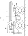
Fig. 1 is a left side view showing a dump truck to which a traveling device according to an embodiment of the present invention is applied. -
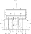
Fig. 2 is a rear view showing the dump truck, as viewed from the backside. -
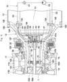
Fig. 3 is a cross section showing a traveling device on the rear wheel side, as viewed in a direction of arrows III-III inFig. 1 . -
Fig. 4 is an enlarged view showing a motor shaft, a rotation shaft, a coupling, a coupling housing and the like inFig. 3 . -
Fig. 5 is an essential-part enlarged view showing an essential part of the coupling, a coupling oil passage, the coupling housing, a housing oil passage, a discharge oil passage and the like. -
Fig. 6 is a cross section showing the coupling as a single unit. -
Fig. 7 is a cross section showing a spline coupling portion between the motor shaft and the coupling, as viewed in a direction of arrows VII-VII inFig. 5 . -
Fig. 8 is an exploded view showing a state where the motor shaft, the rotation shaft, the coupling, the coupling housing and the like are exploded. -
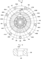
Fig. 9 is a cross section showing the coupling, the coupling oil passage, the coupling housing, the housing oil passage, an oil reservoir portion and the like, as viewed in a direction of arrows IX-IX inFig. 5 . -
Fig. 10 is an enlarged cross section showing a state where an open end of the coupling oil passage is enlarged. -
Fig. 11 is a cross section showing a first modification example regarding the oil reservoir portion in a position as similar to that inFig. 9 . -
Fig. 12 is a cross section showing a second modification example regarding a large-diameter open end of the coupling oil passage. - Hereinafter, a traveling device for a working vehicle according to an embodiment of the present invention will be in detail explained with reference to the accompanying drawings by taking a case of being applied to a dump truck of a rear drive system as an example.
- In
Fig. 1 , adump truck 1 includes avehicle body 2 having a strong frame structure, a vessel (loading platform) 3 mounted on thevehicle body 2 to be capable of lifting and tilting, acab 5 provided in the front part of thevehicle body 2, and left and rightfront wheels 6 and left and rightrear wheels 7 as vehicle wheels. - The
vessel 3 is formed as a large-sized container for loading heavy baggage such as crushed stones. A rear-side bottom part of thevessel 3 is coupled to a rear end side of thevehicle body 2 through acoupling pin 4 or the like to be capable of lifting and tilting (inclination-rotating). In addition, aprotector 3A is integrally provided on a front-side upper part of thevessel 3 in such a manner as to cover thecab 5 from the upper side. Thecab 5 is provided in the front part of thevehicle body 2 to be positioned under theprotector 3A. Thecab 5 forms an operator's room. An operator's seat, a handle for steering, a plurality of control levers (none of them are shown) and the like are arranged inside thecab 5. - The left and right
front wheels 6 are rotatably arranged on the front side of the vehicle body 2 (the left front wheel only is shown). The left and rightfront wheels 6 are configured as steered wheels that are steered by an operator. The left and rightrear wheels 7 are rotatably arranged on the rear side of thevehicle body 2. The left and rightrear wheels 7 are configured as drive wheels of thedump truck 1 and are driven and rotated integrally with awheel attaching cylinder 17 by a travelingdevice 11 as shown inFig. 3 . Therear wheel 7 includes two rows oftires 7A composed of dual tires andrims 7B each located in a radial inside of thetire 7A. - An
engine 8 is positioned under thecab 5 to be provided within thevehicle body 2. Theengine 8 is configured by, for example, a diesel engine or the like, and drives anelectric motor 13, a hydraulic pump (not shown), which will be described later, and the like for rotation, which are mounted on thevehicle body 2. Pressurized oil delivered from the hydraulic pump is supplied to hoistcylinders 9, a steering cylinder for power steering (not shown) and the like. - The
hoist cylinders 9 are provided between thevehicle body 2 and thevessel 3. Thehoist cylinders 9 are positioned between thefront wheel 6 and therear wheel 7 to be located on both left and right sides of thevehicle body 2. Each of thehoist cylinders 9 expands and contracts in the upper-lower direction by delivery/suction of the pressurized oil from/to the hydraulic pump to lift and tilt (inclination-rotate) thevessel 3 around thecoupling pin 4. - An
axle housing 10 on the rear wheel side is provided on a rear side of thevehicle body 2. Theaxle housing 10 is formed as a hollow cylindrical body that extends in the left-right direction. Theaxle housing 10 is attached through left and right rear-wheel side suspensions 10A to the rear side of thevehicle body 2. Thetraveling devices 11 for driving the left and rightrear wheels 7 are provided to both left and right sides of theaxle housing 10 respectively. - The
traveling devices 11 are positioned on both the left and right sides of theaxle housing 10 to be provided in the left and rightrear wheels 7. As shown inFig. 3 , thetraveling device 11 includes aspindle 12, theelectric motor 13, arotation shaft 15, thewheel attaching cylinder 17, agear reduction mechanism 21, acoupling 38, acoupling housing 46, and a lubricatingoil circulation circuit 51. Thetraveling device 11 decelerates rotation of therotation shaft 15 by thegear reduction mechanism 21 and drives the left and rightrear wheels 7 as drive wheels by a large rotational torque for rotation. - The
spindle 12 is attached to each of both the left and right sides of theaxle housing 10. Thespindle 12 is formed in a stepped cylindrical shape extending axially (in the left-right direction) and includes atapered part 12A, an intermediatecylindrical part 12B and a small-diametercylindrical part 12C. Thetapered part 12A is formed in a tapered shape to gradually reduce in diameter from an axial one side (axle housing 10-side) toward an axial other side of thespindle 12 and is attached to an end part of theaxle housing 10 by using a plurality ofbolts 12D. The intermediatecylindrical part 12B is formed integrally with a diameter-reduced side of thetapered part 12A to axially extend. The small-diametercylindrical part 12C has an outer diameter dimension smaller than the intermediatecylindrical part 12B and is formed integrally with a tip end side of the intermediatecylindrical part 12B. - A plurality of
motor attaching seatings 12E projecting to a radial inside of thetapered part 12A are provided on an axial one side of thetapered part 12A and theelectric motor 13 is attached to themotor attaching seatings 12E. Anannular flange part 12F projecting to a radial outside of thetapered part 12A is provided on an outer peripheral side of thetapered part 12A and an after-mentionedwet type brake 35 is attached to theflange part 12F. - On the other hand, a tip end of the small-diameter
cylindrical part 12C is formed as an open end, and acylindrical projection part 33A of an after-mentioned second-stage carrier 33 is spline-coupled to an inner peripheral side of the small-diametercylindrical part 12C. An annular inner-side projection part 12G projecting to a radial inside of the small-diametercylindrical part 12C is formed integrally with an inner peripheral side of an axial intermediate part of the small-diametercylindrical part 12C and an after-mentionedbearing 16 is attached to the inner-side projection part 12G. Further, aradial hole 12H is drilled on a lower side of the small-diametercylindrical part 12C to penetrate therethrough in the upper-lower direction (in a radial direction of the small-diametercylindrical part 12C), and atip end 52A of an after-mentionedsuction pipe 52 is inserted in theradial hole 12H. - The
electric motor 13 for travel is located within theaxle housing 10 and within thetapered part 12A of thespindle 12. A plurality ofattachment flanges 13A are arranged on an outer peripheral side of theelectric motor 13, and theattachment flanges 13A are attached to themotor attaching seatings 12E of the spindle 12 (taperedpart 12A) by using bolts or the like. - A
motor shaft 14 projects out of theelectric motor 13. Theelectric motor 13 drives themotor shaft 14 for rotation by supply of electric power from a power generator (not shown) mounted on thevehicle body 2 to transmit the rotation of themotor shaft 14 to therotation shaft 15. As shown inFig. 5 andFig. 8 , a motorshaft spline portion 14A in which a spline groove is formed is formed on an outer peripheral surface of themotor shaft 14, and the motorshaft spline portion 14A is engaged to a motor shaft-sidehole spline portion 39 of an after-mentionedcoupling 38. A bottomedstopper attaching hole 14C is provided in aprojection end 14B of themotor shaft 14, and a bolt hole (female screw hole) 14D is formed in the center of a bottom of thestopper attaching hole 14C. - The
rotation shaft 15 is provided on an inner peripheral side of thespindle 12 to axially extend therein. Therotation shaft 15 is formed by a single elongated bar-shaped body. A rotationshaft spline portion 15A is formed on an outer peripheral surface of one end side of the rotation shaft 15 (electric motor 13-side), and the rotationshaft spline portion 15A is engaged to a rotation shaft-sidehole spline portion 40 of the after-mentionedcoupling 38. In this way, therotation shaft 15 is jointed via thecoupling 38 to themotor shaft 14 of theelectric motor 13 and is driven and rotated by theelectric motor 13. The other end side of therotation shaft 15 projects out of the open end of the small-diametercylindrical part 12C of thespindle 12. An after-mentionedsun gear 23 is attached to the other end (projection end) of therotation shaft 15. The axial intermediate part of therotation shaft 15 is rotatably supported by the bearing 16 attached on the inner-side projection part 12G of thespindle 12. - The
wheel attaching cylinder 17 is rotatably provided via tworoller bearings 18 on an outer peripheral side of the small-diametercylindrical part 12C configuring part of thespindle 12. Thewheel attaching cylinder 17 is supported by the tworoller bearings 18 and includes a hollowcylindrical part 17A axially extending on the outer peripheral side of the small-diametercylindrical part 12C and an extensioncylindrical part 17B that projects axially from a tip end of the hollowcylindrical part 17A and extends in a direction away from thespindle 12. Thecylindrical rim 7B configuring part of therear wheel 7 is removably attached to the outer peripheral side of thewheel attaching cylinder 17, and therear wheel 7 rotates integrally with thewheel attaching cylinder 17. An after-mentionedinternal gear 32 and anouter drum 19 are fixed integrally to an end part of the extensioncylindrical part 17B of thewheel attaching cylinder 17 by usingelongated bolts 20. Theouter drum 19 is composed of a cylindrical body, and aflange part 19A provided on an axial one side of theouter drum 19. Theouter drum 19 is fixed via theinternal gear 32 to thewheel attaching cylinder 17, and an axial other side of theouter drum 19 is formed as an open end. - The
gear reduction mechanism 21 is provided between therotation shaft 15 and thewheel attaching cylinder 17. Thegear reduction mechanism 21 is configured by a first-stage planetarygear reduction mechanism 22 and a second-stage planetarygear reduction mechanism 29. Thegear reduction mechanism 21 decelerates the rotation of therotation shaft 15 by two stages, which is transmitted to thewheel attaching cylinder 17. - The first-stage planetary
gear reduction mechanism 22 includes thesun gear 23, a plurality ofplanetary gears 24 and acarrier 26. Thesun gear 23 is spline-coupled to a tip end of therotation shaft 15 projecting out of the spindle 12 (small-diametercylindrical part 12C). The plurality ofplanetary gears 24 are engaged to thesun gear 23 and a ring-shapedinternal gear 25, and rotate and revolve around thesun gear 23. Thecarrier 26 is fixed on an open end of theouter drum 19 integral with thewheel attaching cylinder 17 by bolts or the like and rotatably supports the plurality ofplanetary gears 24 through support pins 27. - Here, the
internal gear 25 is formed by using a ring gear to surround thesun gear 23 and the plurality ofplanetary gears 24 from a radial outside thereof. Theinternal gear 25 is located through a radial gap to an inner peripheral surface of theouter drum 19 to be rotatable relative to theouter drum 19. The rotation of theinternal gear 25 is transmitted through acoupling 28 to the second-stage planetarygear reduction mechanism 29. - The
coupling 28 is provided in a position between the first-stage planetarygear reduction mechanism 22 and the second-stage planetarygear reduction mechanism 29. Thecoupling 28 is formed in a disc shape with aboss 28A in the center part. An outer peripheral side of thecoupling 28 is spline-coupled to the first-stageinternal gear 25. An inner peripheral side of theboss 28A in thecoupling 28 is spline-coupled to a second-stage sun gear 30. Thecoupling 28 transmits rotation of the first-stageinternal gear 25 to the second-stage sun gear 30 to cause thesun gear 30 to rotate integrally with the first-stageinternal gear 25. - As the
sun gear 23 is rotated integrally with therotation shaft 15 by theelectric motor 13, the first-stage planetarygear reduction mechanism 22 converts the rotation of thesun gear 23 into a rotating movement of the plurality ofplanetary gears 24 on its axis and a revolving movement thereof. Further, the rotating movement on its axis of theplanetary gears 24 is transmitted to theinternal gear 25 as the decelerated rotation and the rotation of theinternal gear 25 is transmitted through thecoupling 28 to the second-stage planetarygear reduction mechanism 29. On the other hand, the revolving movement of theplanetary gears 24 is transmitted via theouter drum 19 to thewheel attaching cylinder 17 as rotation of thecarrier 26. At this time, since thewheel attaching cylinder 17 rotates integrally with the second-stageinternal gear 32, the revolving movement of theplanetary gears 24 is controlled to the rotation synchronized with thewheel attaching cylinder 17. - The second-stage planetary
gear reduction mechanism 29 includes thecylindrical sun gear 30, a plurality ofplanetary gears 31, and thecarrier 33. Thesun gear 30 is spline-coupled to an inner peripheral side of theboss 28A in thecoupling 28 to rotate integrally with thecoupling 28. The plurality ofplanetary gears 31 are engaged to thesun gear 30 and the ring-shapedinternal gear 32 to rotate and revolve around thesun gear 30. Thecarrier 33 rotatably supports theplanetary gears 31 through support pins 34. Acylindrical projection part 33A in a cylindrical shape is provided in the center part of thecarrier 33 and an outer peripheral side of thecylindrical projection part 33A is spline-coupled to an inner peripheral side of the small-diametercylindrical part 12C. Here, the second-stageinternal gear 32 is formed by using a ring gear surrounding thesun gear 30, the plurality ofplanetary gears 31, and the like from a radial outside thereof. Theinternal gear 32 is fixed integrally between the extensioncylindrical part 17B in thewheel attaching cylinder 17 and theouter drum 19 by using the elongatedbolts 20. - In the second-stage planetary
gear reduction mechanism 29, thecylindrical projection part 33A of thecarrier 33 is spline-coupled to the small-diametercylindrical part 12C of thespindle 12. Therefore, the revolving movement of the planetary gear 31 (rotation of the carrier 33) is restrained. As a result, when thesun gear 30 rotates integrally with thecoupling 28, the second-stage planetarygear reduction mechanism 29 converts the rotation of thesun gear 30 into a rotating movement of theplanetary gear 31 and transmits the rotating movement of theplanetary gear 31 to the second-stageinternal gear 32. With this configuration, theinternal gear 32 decelerates and rotates, and rotational torque of large output decelerated by two stages in the first-stage planetarygear reduction mechanism 22 and in the second-stage planetarygear reduction mechanism 29 is transmitted to thewheel attaching cylinder 17 to which theinternal gear 32 is fixed. - Here, lubricating oil L is stored in the inside of the
wheel attaching cylinder 17, and a liquid surface of the lubricating oil L is in a position lower than the lowest part of the small-diametercylindrical part 12C configuring part of thespindle 12, for example. Therefore, a lower part of theroller bearing 18 is immersed in the lubricating oil L and part of the planetarygear reduction mechanisms gear reduction mechanisms spindle 12, which is supplied also to thebearing 16 supporting therotation shaft 15. As a result, at the operating of the travelingdevice 11, the resistance against the stirring of the lubricating oil L is made small, making it possible to suppress the energy loss and heat generation of the travelingdevice 11. - The
wet type brake 35 is attached to theflange part 12F of thespindle 12. Thewet type brake 35 is configured of a wet multi-plate type of hydraulic brake and applies braking forces to abrake hub 36 attached to thewheel attaching cylinder 17. With this configuration, braking forces are applied to the rotation of thewheel attaching cylinder 17, that is, the rotation of therear wheel 7. - A
partition wall 37 is provided within thespindle 12. Thepartition wall 37 is formed by an annual plate body. An outer peripheral side of thepartition wall 37 is attached on a boundary part between thetapered part 12A and the intermediatecylindrical part 12B of thespindle 12 by using bolts or the like. Thepartition wall 37 partitions the inside of thespindle 12 into a motor accommodatingspace part 37A accommodating theelectric motor 13 and acylindrical space part 37B communicating with the inside of thewheel attaching cylinder 17. - The
coupling 38 is located in the center part of theannular partition wall 37 to establish joint between themotor shaft 14 of theelectric motor 13 and therotation shaft 15. As shown inFig. 5 to Fig. 8 , thecoupling 38 is formed in a cylindrical shape as a whole and the motor shaft-sidehole spline portion 39 in which a spline groove is provided is formed on an inner peripheral surface of an axial one side (motor shaft 14-side) of thecoupling 38. The motor shaft-sidehole spline portion 39 is spline-coupled to the motorshaft spline portion 14A of themotor shaft 14. As shown inFig. 7 , a tooth bottom circle diameter D1 of the motor shaft-sidehole spline portion 39 is set to be larger than a tooth tip circle diameter D2 of the motorshaft spline portion 14A (D1 > D2) . Therefore,gaps 38A are formed between tooth bottoms of a plurality of teeth configuring part of the motor shaft-sidehole spline portion 39 and tooth tips of a plurality of teeth configuring part of the motorshaft spline portion 14A. Thegap 38A is formed over an entire region of thespline coupling portion 39A in the length direction to which the motorshaft spline portion 14A and the motor shaft-sidehole spline portion 39 are engaged. - The rotation shaft-side
hole spline portion 40 in which a spline groove is provided is formed on an inner peripheral surface of an axial other side (rotation shaft 15-side) of thecoupling 38. The rotation shaft-sidehole spline portion 40 is spline-coupled to the rotationshaft spline portion 15A of therotation shaft 15. A tooth bottom circle diameter of the rotation shaft-sidehole spline portion 40 is set to be larger than a tooth tip circle diameter of the rotationshaft spline portion 15A. Therefore, gaps (not shown) are formed between tooth bottoms of a plurality of teeth configuring part of the rotation shaft-sidehole spline portion 40 and tooth tips of a plurality of teeth configuring part of the rotationshaft spline portion 15A. The gap is formed over an entire region of aspline coupling portion 40A in the length direction to which the rotationshaft spline portion 15A and the rotation shaft-sidehole spline portion 40 are engaged. - A
stopper fitting portion 41 is formed on an inner peripheral surface of an axial intermediate part of thecoupling 38 to be positioned between the motor shaft-sidehole spline portion 39 and the rotation shaft-sidehole spline portion 40. A portion, which is adjacent to the motor shaft-sidehole spline portion 39, of thestopper fitting portion 41 serves as anannular oil passage 41A having an inner diameter dimension larger than thestopper fitting portion 41, and an after-mentionedcoupling oil passage 43 opens to theannular oil passage 41A. - A sleeve
fitting portion 38B is provided on an end surface of an axial one side of thecoupling 38. An after-mentionedsleeve 45 is fitted in the sleevefitting portion 38B. Anannular groove 38C is formed over an entire periphery on an inner peripheral surface of thecoupling 38 in which the motor shaft-sidehole spline portion 39 is formed. A C-letter type of astop ring 42 for hole is attached to theannular groove 38C. As shown inFig. 7 , an outer diameter dimension of thestop ring 42 for hole attached to theannular groove 38C is set to be smaller than the tooth tip circle diameter D2 of the motorshaft spline portion 14A spline-coupled to the motor shaft-sidehole spline portion 39. Therefore, thegap 38A formed between the tooth bottom of the motor shaft-sidehole spline portion 39 and the tooth tip of the motorshaft spline portion 14A is not closed by thestop ring 42 for hole. - The
coupling oil passage 43 is provided in the axial intermediate part of thecoupling 38. Thecoupling oil passage 43 supplies the lubricating oil L to thespline coupling portion 39A between the motor shaft 14 (the motorshaft spline portion 14A) and the coupling 38 (the motor shaft-side hole spline portion 39) and to thespline coupling portion 40A between the rotation shaft 15 (the rotationshaft spline portion 15A) and the coupling 38 (the rotation shaft-side hole spline portion 40). Thecoupling oil passage 43 is formed by a plurality of oil passages radially extending by equal angular intervals from the center of thecoupling 38. Thecoupling oil passage 43 penetrates from theannular oil passage 41A of thestopper fitting portion 41 through the outer peripheral surface of thecoupling 38. With this configuration, thecoupling oil passage 43 opens to (is communicated with) an after-mentionedoil reservoir portion 50. A portion, which opens to the after-mentionedoil reservoir portion 50, of thecoupling oil passage 43 is formed as a tapered large-diameteropen end 43A having a diameter larger than the coupling oil passage 43 (Refer toFig. 10 ). - A
stopper 44 is removably attached to theprojection end 14B-side of themotor shaft 14 by using astopper bolt 44A. As shown inFig. 8 , thestopper 44 is formed in a stepped cylindrical shape as a whole and is provided with a small-diameterfitting portion 44B and a large-diameter fitting portion 44C. The small-diameterfitting portion 44B is fitted in thestopper attaching hole 14C of themotor shaft 14. The large-diameter fitting portion 44C has an outer diameter dimension larger than the small-diameterfitting portion 44B and is fitted in the tooth tip circle of the motor shaft-sidehole spline portion 39 of thecoupling 38. Thestopper 44 radially positions thecoupling 38 relative to themotor shaft 14 when the large-diameter fitting portion 44C is fitted in the tooth tip circle of the motor shaft-sidehole spline portion 39. A boundary part between the small-diameterfitting portion 44B and the large-diameter fitting portion 44C becomes anannular step part 44D, and theannular step part 44D axially faces theprojection end 14B of themotor shaft 14. - A bolt through
hole 44E is formed in the center part of the small-diameterfitting portion 44B to penetrate therethrough axially. A bottomedcounterbore 44F is formed in the large-diameter fitting portion 44C concentrically with the bolt throughhole 44E. Thestopper 44 causes the small-diameterfitting portion 44B to be fitted in thestopper attaching hole 14C of themotor shaft 14, and puts thestop ring 42 for hole in between theannular step part 44D and theprojection end 14B of themotor shaft 14. In this state, thestopper bolt 44A inserted in the bolt throughhole 44E is screwed into thebolt hole 14D of themotor shaft 14. As a result, thestopper 44 is attached to themotor shaft 14 and a head of thestopper bolt 44A is accommodated in thecounterbore 44F. - In addition, the plurality of
stopper oil passages 44G are formed in thestopper 44 to penetrate through an outer peripheral surface of the large-diameter fitting portion 44C from thecounterbore 44F. Thestopper oil passage 44G comprises a plurality of oil passages radially extending by equal angular intervals from the center of thestopper 44. In a state where the motor shaft-sidehole spline portion 39 of thecoupling 38 is spline-coupled to the motorshaft spline portion 14A of themotor shaft 14, thestopper oil passages 44G are communicated via theannular oil passage 41A of thestopper fitting portion 41 provided in thecoupling 38 with thecoupling oil passage 43. With this configuration, as shown inFig. 5 , the lubricating oil L supplied to thecoupling oil passage 43 of thecoupling 38 flows to theannular oil passage 41A of thecoupling 38, thestopper oil passages 44G of thestopper 44 and thecounterbore 44F. In addition, the lubricating oil L is distributed to thespline coupling portion 39A between the motor shaft-sidehole spline portion 39 and the motorshaft spline portion 14A and to thespline coupling portion 40A between the rotation shaft-sidehole spline portion 40 and the rotationshaft spline portion 15A. - The
sleeve 45 is provided between the axial one side of thecoupling 38 and themotor shaft 14. Thesleeve 45 is formed in a stepped cylindrical shape composed of a small-diametercylindrical part 45A and a large-diametercylindrical part 45B. An inner peripheral side of thesleeve 45 is fitted into themotor shaft 14 and an outer peripheral side of the small-diametercylindrical part 45A is fitted into the sleevefitting portion 38B of thecoupling 38. Thesleeve 45 radially positions the axial one side of thecoupling 38 relative to themotor shaft 14. - Next, an explanation will be made of the
coupling housing 46 to be used in the present embodiment by referring fromFig. 8 to Fig. 10 . - The
coupling housing 46 is attached to theelectric motor 13 to surround the outer peripheral side of thecoupling 38. Thecoupling housing 46 is provided with acylindrical part 46A to surround the outer peripheral side of thecoupling 38 and aflange part 46B of which a diameter is enlarged from an axial one side of thecylindrical part 46A (electric motor 13-side). Theflange part 46B is attached to theelectric motor 13 by usingbolts 46C. On the other hand, a couplingfitting portion 46D is provided on an axial other side of thecylindrical part 46A. An inner peripheral surface of the couplingfitting portion 46D is slidably fitted into the outer peripheral surface of thecoupling 38 to suppress the misalignment of thecoupling 38. In addition, the after-mentionedoil reservoir portion 50 is formed on an inner peripheral surface of the couplingfitting portion 46D. - A
housing oil passage 47 positioned above thecoupling 38 and adischarge oil passage 48 positioned under thecoupling 38 are formed in thecylindrical part 46A of thecoupling housing 46. Thehousing oil passage 47 branches part of the lubricating oil L flowing in the lubricatingoil circulation circuit 51 to be introduced to thecoupling oil passage 43 of thecoupling 38. Oneend 47A of thehousing oil passage 47 opens to an outer peripheral surface of thecylindrical part 46A to be connected to an after-mentionedcoupling lubricating pipe 59. On the other hand, theother end 47B of thehousing oil passage 47 is connected to theoil reservoir portion 50 formed on the inner peripheral surface of the couplingfitting portion 46D and is communicated via theoil reservoir portion 50 with thecoupling oil passage 43. In addition, twoseal rings 49 sandwiching theoil reservoir portion 50 axially are arranged on the inner peripheral surface of the couplingfitting portion 46D. The twoseal rings 49 perform sealing between the couplingfitting portion 46D and thecoupling 38 by an inner peripheral edge of each of the twoseal rings 49 coming in sliding contact with an outer peripheral surface of thecoupling 38. - The
oil reservoir portion 50 is formed on the inner peripheral surface of the couplingfitting portion 46D configuring part of thecoupling housing 46. Theoil reservoir portion 50 is communicated with thehousing oil passage 47 and thecoupling oil passage 43 in a state of covering thecoupling 38 from the outer peripheral side. Theoil reservoir portion 50 is formed as a circular groove having an internal diameter dimension larger than the couplingfitting portion 46D and is located between the two seal rings 49. Theoil reservoir portion 50 is made eccentric to a radially upper side (the housing oil passage 47-side) from the center of the couplingfitting portion 46D, that is, a rotational center of thecoupling 38. In addition, an upper end side of theoil reservoir portion 50 is communicated with theother end 47B of the housing oil passage 47 (Refer toFig.9 ). - Here, the
oil reservoir portion 50 is made eccentric to the radially upper side from the center of the couplingfitting portion 46D (the rotational center of the coupling 38). Because of this configuration, theoil reservoir portion 50 is shaped so that a capacity of a portion, which is positioned in the radially upper side, of thecoupling housing 46 is made larger than a capacity of a portion, which is positioned in the radially lower side, of thecoupling housing 46. That is, theoil reservoir portion 50 includes a wide-widthoil reservoir portion 50A that is positioned above thecoupling 38 and has a wide interval to the outer peripheral surface of thecoupling 38 and a narrow-widthoil reservoir portion 50B that is positioned under thecoupling 38 and has a narrow interval to the outer peripheral surface of thecoupling 38. The lubricating oil L stored in the wide-widthoil reservoir portion 50A smoothly flows downward by its own weight, and thereby, the lubricating oil L flows through thecoupling oil passage 43 into the inner peripheral side of thecoupling 38. Because of this, the lubricating oil L is smoothly supplied to thespline coupling portion 39A between themotor shaft 14 and thecoupling 38 and to thespline coupling portion 40A between therotation shaft 15 and thecoupling 38. - At the time of coupling the
motor shaft 14 and therotation shaft 15 by using thecoupling 38, the large-diameter fitting portion 44C of thestopper 44 is caused to be fitted into thestopper fitting portion 41 in thecoupling 38. On the other hand, thestop ring 42 for hole is attached to theannular groove 38C of thecoupling 38, and thestop ring 42 for hole is caused to abut on theannular step part 44D of thestopper 44. This arrangement positions thestopper 44 in the axial direction of thecoupling 38. - Next, the motor shaft-side
hole spline portion 39 in thecoupling 38 is spline-coupled to the motorshaft spline portion 14A of themotor shaft 14. In addition, in a state where thestop ring 42 for hole has abutted on theprojection end 14B of themotor shaft 14, thestopper bolt 44A is caused to be screwed into thebolt hole 14D of themotor shaft 14. In this way, the rotationshaft spline portion 15A of therotation shaft 15 is spline-coupled to the rotation shaft-sidehole spline portion 40 of thecoupling 38 attached to themotor shaft 14, and therotation shaft 15 is axially inserted into thecoupling 38. With this configuration, as shown inFig. 5 themotor shaft 14 and therotation shaft 15 can be coupled by using thecoupling 38. - In this state, the
coupling oil passage 43 of thecoupling 38 is caused to be communicated with theoil reservoir portion 50 of thecoupling housing 46 and thestopper oil passage 44G of thestopper 44 becomes communicated with theannular oil passage 41A of thestopper fitting portion 41 provided in thecoupling 38. On the other hand, as shown inFig. 7 , thegap 38A is formed between a tooth bottom of the motor shaft-sidehole spline portion 39 formed in thecoupling 38 and a tooth tip of the motorshaft spline portion 14A. Similarly, a gap (not shown) is formed also between a tooth bottom of the rotation shaft-sidehole spline portion 40 formed in thecoupling 38 and a tooth tip of the rotationshaft spline portion 15A. - The lubricating
oil circulation circuit 51 is provided in the inside of thespindle 12 and theaxle housing 10. The main circuit of the lubricatingoil circulation circuit 51 is configured of asuction pipe 52, a lubricatingoil pump 53, adelivery pipe 55, asupply pipe 56 and the like. The lubricatingoil circulation circuit 51 repeatedly supplies the lubricating oil L stored in the inside of thewheel attaching cylinder 17 to thegear reduction mechanism 21, theroller bearing 18, thebearing 16 and the like. In addition, the lubricatingoil circulation circuit 51 is provided with an after-mentioned couplingportion lubricating circuit 58. - The
suction pipe 52 is provided within thespindle 12 and theaxle housing 10. A longitudinal one side of thesuction pipe 52 is connected to a suction port of the lubricatingoil pump 53. A longitudinal other side of thesuction pipe 52 is located under therotation shaft 15 to extend in the axial direction of thespindle 12. Thetip end 52A of thesuction pipe 52 is inserted in theradial hole 12H of thespindle 12 and is immersed in the lubricating oil L within thewheel attaching cylinder 17. The lubricatingoil pump 53 sucks up the lubricating oil L through thesuction pipe 52. - A
branch joint 54 is provided in themotor attaching seating 12E provided in thespindle 12. The branch joint 54 is provided with a single inlet port and two outlet ports different in a flow quantity from each other (none of them are shown), for example. Thedelivery pipe 55 establishes connection between a delivery port of the lubricatingoil pump 53 and the inlet port of thebranch joint 54. The lubricating oil L delivered from the lubricatingoil pump 53 flows through thedelivery pipe 55 into the branch joint 54 and is branched into two pathways by thesupply pipe 56 and the after-mentionedcoupling lubricating pipe 59 connected to the two outlet ports of thebranch joint 54. In addition, anoil cooler 57 is provided in the middle of thedelivery pipe 55. - The
supply pipe 56 is provided within thespindle 12. One end of thesupply pipe 56 is connected to an outlet port, of which a flow quantity is larger, out of the two outlet ports of thebranch joint 54. A longitudinal other end of thesupply pipe 56 is located above therotation shaft 15 and extends in the axil direction of thespindle 12. Atip end 56A of thesupply pipe 56 extends along therotation shaft 15 into thecylindrical projection part 33A of the second-stage carrier 33. With this configuration, most of the lubricating oil L delivered from the lubricatingoil pump 53 is cooled by theoil cooler 57, and in that state, the lubricating oil L is supplied via thetip end 56A of thesupply pipe 56 to therotation shaft 15. The cooled lubricating oil L cools therotation shaft 15 and is scattered from therotation shaft 15, whereby thebearing 16 and the like are lubricated. - The coupling
portion lubricating circuit 58 branches part of the lubricating oil L to be supplied to thegear reduction mechanism 21 and the like, which is supplied to the coupling portion (spline coupling portion 39A) between themotor shaft 14 and thecoupling 38 and to the coupling portion (spline coupling portion 40A) between therotation shaft 15 and thecoupling 38. The couplingportion lubricating circuit 58 is configured by thecoupling lubricating pipe 59, thehousing oil passage 47 and theoil reservoir portion 50 of thecoupling housing 46, thecoupling oil passage 43 of thecoupling 38, thestopper oil passage 44G and thecounterbore 44F of thestopper 44, and the like. - The
coupling lubricating pipe 59 is provided within thespindle 12 together with thesupply pipe 56. One end of thecoupling lubricating pipe 59 is connected to an outlet port, of which a flow quantity is smaller, out of the two outlet ports of thebranch joint 54. Theother end 59A of thecoupling lubricating pipe 59 is connected to Oneend 47A of thehousing oil passage 47 formed in thecoupling housing 46. With this configuration, part of the lubricating oil L delivered from the lubricatingoil pump 53 is introduced from thecoupling lubricating pipe 59 configuring part of the couplingportion lubricating circuit 58 through thehousing oil passage 47 in thecoupling housing 46 to thecoupling oil passage 43 of thecoupling 38. - The lubricating oil L introduced into the
coupling oil passage 43 is branched into a pathway indicated by an arrow F1 and a pathway indicated by an arrow F2 inFig. 5 . The lubricating oil L flowing in the pathway of the arrow F1 is supplied from thecoupling oil passage 43 through theannular oil passage 41A of thestopper fitting portion 41 to the motor shaft-sidehole spline portion 39. In this case, thegap 38A is formed between the tooth bottom of the motor shaft-sidehole spline portion 39 and the tooth tip of the motorshaft spline portion 14A. With this configuration, the lubricating oil L flows through thegap 38A into the motor shaft-sidehole spline portion 39 in the axial direction to lubricate thespline coupling portion 39A between the motor shaft-sidehole spline portion 39 and the motorshaft spline portion 14A. - On the other hand, the lubricating oil L flowing in the pathway of the arrow F2 is supplied from the
coupling oil passage 43 through thestopper oil passage 44G and thecounterbore 44F of thestopper 44 to the rotation shaft-sidehole spline portion 40. In this case, the gap (not shown) is formed between the tooth bottom of the rotation shaft-sidehole spline portion 40 and the tooth tip of the rotationshaft spline portion 15A. Because of this configuration, the lubricating oil L flows through the gap into the rotation shaft-sidehole spline portion 40 in the axial direction to lubricate thespline coupling portion 40A between the rotation shaft-sidehole spline portion 40 and the rotationshaft spline portion 15A. - The traveling
device 11 for thedump truck 1 according to the present embodiment has the configuration as described above, and next, an operation thereof will be explained. - When an operator which gets in the
cab 5 of thedump truck 1 activates theengine 8, the hydraulic pump is driven and rotated, and electric power is generated by the power generator (none thereof are shown). At the time thedump truck 1 is driven to travel, the electric power is supplied from the power generator to theelectric motor 13. Thereby theelectric motor 13 is activated to rotate therotation shaft 15. - The rotation of the
rotation shaft 15 is decelerated by two states by the first-stage planetarygear reduction mechanism 22 and the second-stage planetarygear reduction mechanism 29 configuring thegear reduction mechanism 21, which is transmitted to thewheel attaching cylinder 17 and thewheel attaching cylinder 17 rotates with a large rotational toque. As a result, the left and rightrear wheels 7 as drive wheels rotate integrally with thewheel attaching cylinder 17, making it possible to cause thedump truck 1 to travel. - At the operating of the traveling
device 11, the lubricating oil L stored in thewheel attaching cylinder 17 is stirred by theplanetary gears gear reduction mechanisms roller bearing 18, thebearing 16 and the like. In addition, the lubricating oil L sequentially drops downward to be collected to a lower side of thewheel attaching cylinder 17. - The lubricating oil L collected in the lower side of the
wheel attaching cylinder 17 is sucked up from thetip end 52A of thesuction pipe 52 by the lubricatingoil pump 53, which is delivered to thedelivery pipe 55. After the lubricating oil L delivered to thedelivery pipe 55 is cooled by theoil cooler 57, the cooled lubricating oil L flows into thebranch joint 54. Most of the lubricating oil L having flowed into the branch joint 54 is introduced to thesupply pipe 56, which is then supplied through thetip end 56A of thesupply pipe 56 to therotation shaft 15. With this configuration, therotation shaft 15 can be cooled by the lubricating oil L, and thebearing 16 and the like can be lubricated by the lubricated oil L scattered from therotation shaft 15. - The lubricating oil L introduced to the
coupling lubricating pipe 59 from the branch joint 54 flows through thehousing oil passage 47 of thecoupling housing 46 into theoil reservoir portion 50. The lubricating oil L is temporally stored in theoil reservoir portion 50 and is thereafter introduced through thecoupling oil passage 43 in thecoupling 38 to theannular oil passage 41A. The lubricating oil L introduced to theannular oil passage 41A is branched into the pathway indicated by the arrow F1 and the pathway indicated by the arrow F2 inFig. 5 . - The lubricating oil L flowing in the pathway of the arrow F1 is supplied from the
coupling oil passage 43 through theannular oil passage 41A to the motor shaft-sidehole spline portion 39. In this case, thegap 38A is formed between the tooth bottom of the motor shaft-sidehole spline portion 39 and the tooth tip of the motorshaft spline portion 14A. With this configuration, the lubricating oil L flows through thegap 38A into the motor shaft-sidehole spline portion 39 in the axial direction, making it possible to lubricate thespline coupling portion 39A between the motor shaft-sidehole spline portion 39 and the motorshaft spline portion 14A by the lubricating oil L. The residual amount of the lubricating oil L supplied to thespline coupling portion 39A between the motor shaft-sidehole spline portion 39 and the motorshaft spline portion 14A flows downward from the fitting portion between the coupling 38 (the sleevefitting portion 38B) and thesleeve 45 into thecoupling housing 46. The lubricating oil L is discharged through thedischarge oil passage 48 to an exterior of the coupling housing 46 (inside the spindle 12). With this configuration, the lubricating oil L can be prevented from leaking to the electric motor 13-side, thus protecting theelectric motor 13. - On the other hand, the lubricating oil L flowing in the pathway of the arrow F2 is supplied from the
coupling oil passage 43 through theannular oil passage 41A, thestopper oil passage 44G and thecounterbore 44F in thestopper 44 to the rotation shaft-sidehole spline portion 40. In this case, the gap (not shown) is formed between the tooth bottom of the rotation shaft-sidehole spline portion 40 and the tooth tip of the rotationshaft spline portion 15A. With this configuration, the lubricating oil L flows through the gap into the rotation shaft-sidehole spline portion 40 in the axial direction, making it possible to lubricate thespline coupling portion 40A between the rotation shaft-sidehole spline portion 40 and the rotationshaft spline portion 15A. The residual amount of the lubricating oil L supplied to thespline coupling portion 40A between the rotation shaft-sidehole spline portion 40 and the rotationshaft spline portion 15A is discharged to the outer peripheral surface of therotation shaft 15 from the rotationshaft spline portion 15A. The lubricating oil L scatters into thespindle 12 in a mist shape due to the rotation of therotation shaft 15 to lubricate thebearing 16 that supports therotation shaft 15. - Here, when the
coupling 38 rotates at high speeds by theelectric motor 13, a large centrifugal force acts on thecoupling 38, thereby making it possible to interrupt the flow of the lubricating oil L introduced through thecoupling oil passage 43 to theannular oil passage 41A. Therefore, the lubricating property to thespline coupling portion 39A between themotor shaft 14 andcoupling 38 and to thespline coupling portion 40A between therotation shaft 15 andcoupling 38 possibly deteriorates. - On the other hand, in the traveling
device 11 according to the present embodiment, theoil reservoir portion 50 is formed in the couplingfitting portion 46D of thecoupling housing 46 to be communicated with thehousing oil passage 47 and thecoupling oil passage 43 and temporarily store the lubricating oil L therein. Theoil reservoir portion 50 is made eccentric to the upper side from the center of the couplingfitting portion 46D. Because of this configuration, theoil reservoir portion 50 includes the wide-widthoil reservoir portion 50A that has the wide interval to the outer peripheral surface of thecoupling 38 and the narrow-widthoil reservoir portion 50B that has the narrow interval to the outer peripheral surface of thecoupling 38. The capacity of the wide-widthoil reservoir portion 50A which is positioned in the radially upper side of thecoupling housing 46 is made larger than the capacity of the narrow-widthoil reservoir portion 50B which is positioned in the radially lower side of thecoupling housing 46. - Therefore, the lubricating oil L stored in the wide-width
oil reservoir portion 50A smoothly flows downward through thecoupling oil passage 43 by its own weight. Accordingly, even in a state where the large centrifugal force acts on thecoupling 38 at the high-speed rotation, the lubricating oil L is smoothly introduced through thecoupling oil passage 43 into theannular oil passage 41A. As a result, even in a case where thecoupling 38 rotates at high speeds, a sufficient amount of the lubricating oil L can be supplied to thespline coupling portion 39A between themotor shaft 14 and thecoupling 38 and to thespline coupling portion 40A between therotation shaft 15 and thecoupling 38, making it possible to highly improve the lubricating property. - In addition, the portion, which opens to the
oil reservoir portion 50, of thecoupling oil passage 43 is formed as the tapered large-diameteropen end 43A having the diameter larger than thecoupling oil passage 43. Because of the configuration, the lubricating oil L stored in theoil reservoir portion 50 can further smoothly be introduced to thecoupling oil passage 43. Therefore, a sufficient amount of the lubricating oil L can be supplied to thespline coupling portion 39A between themotor shaft 14 and thecoupling 38 and to thespline coupling portion 40A between therotation shaft 15 and thecoupling 38 from thecoupling oil passage 43 through theannular oil passage 41A and the like. - In this way, the traveling device 11 for the working vehicle according to the embodiment includes: the electric motor 13 that is provided on the vehicle body in the working vehicle having the vehicle wheels; the motor shaft 14 that outputs the rotation of the electric motor 13; the rotation shaft 15 to which the rotation of the motor shaft 14 is transmitted; the gear reduction mechanism 21 that decelerates the rotation of the rotation shaft 15 and transmits the decelerated rotation to the vehicle wheels; the lubricating oil circulation circuit 51 that supplies the lubricating oil L to the gear reduction mechanism 21; the cylindrical coupling 38 for joint between the motor shaft 14 and the rotation shaft 15; the coupling housing 46 that is provided in the electric motor 13 to be provided with the fitting portion slidably fitted on the outer peripheral surface of the coupling 38; the coupling oil passage 43 that is provided in the coupling 38 to supply the lubricating oil L to the spline coupling portion 39A between the motor shaft 14 and the coupling 38 and to the spline coupling portion 40A between the rotation shaft 15 and the coupling 38; and the housing oil passage 47 that is provided in the coupling housing 46 to branch part of the lubricating oil L flowing in the lubricating oil circulation circuit 51 to be introduced to the coupling oil passage 43, characterized by including the oil reservoir portion 50 that is provided in the coupling housing 46 to be communicated with the housing oil passage 47 and the coupling oil passage 43 in a state where the coupling 38 is covered from the outer peripheral side thereof and to store the lubricating oil L to be supplied through the coupling oil passage 43 to the spline coupling portion 39A between the motor shaft 14 and the coupling 38 and to the spline coupling portion 40A between the rotation shaft 15 and the coupling 38, wherein the oil reservoir portion 50 is shaped so that the capacity of the portion positioned on the radially upper side of the coupling housing 46 is larger than the capacity of the portion positioned on the radially lower side of the coupling housing 46.
- According to this configuration, the lubricating oil L stored in the portion, which has the shape of which the capacity becomes larger, of the
oil reservoir portion 50 in thecoupling housing 46 smoothly flows downward by its own weight. Because of this, even in a state where the large centrifugal force acts on thecoupling 38 at the high-speed rotation, the lubricating oil L is smoothly introduced through thecoupling oil passage 43 into theannular oil passage 41A. As a result, also at the high-speed rotation of the coupling 38 a sufficient amount of the lubricating oil L can be supplied to thespline coupling portion 39A between themotor shaft 14 and thecoupling 38 and to thespline coupling portion 40A between therotation shaft 15 and thecoupling 38, appropriately lubricating thespline coupling portions - In the embodiment, the
oil reservoir portion 50 is formed in the circular shape made eccentric to the radially upper side from the rotational center of thecoupling 38. According to this configuration, the capacity of the portion, which is made eccentric to the rotational center of thecoupling 38, of theoil reservoir portion 50 can be made larger. - In the embodiment, the
oil reservoir portion 50 includes the wide-widthoil reservoir portion 50A that has the wide interval to the outer peripheral surface of thecoupling 38 and the narrow-widthoil reservoir portion 50B that has the narrow interval to the outer peripheral surface of thecoupling 38. The wide-widthoil reservoir portion 50A is located in the radially upper side of thecoupling housing 46. According to this configuration, even in a case where thecoupling 38 rotates at high speeds, the lubricating oil L stored in the wide-widthoil reservoir portion 50A can smoothly flow into thecoupling oil passage 43 by its own weight. - In the embodiment, the large-diameter
open end 43A having the diameter larger than thecoupling oil passage 43 is formed in the portion, which opens to theoil reservoir portion 50, of thecoupling oil passage 43. Because of the configuration, the lubricating oil L stored in theoil reservoir portion 50 can further smoothly be introduced to thecoupling oil passage 43. A sufficient amount of the lubricating oil L can be supplied to thespline coupling portion 39A between themotor shaft 14 and thecoupling 38 and to thespline coupling portion 40A between therotation shaft 15 and thecoupling 38. - It should be noted that in the embodiment, the
oil reservoir portion 50 provided in thecoupling housing 46 is formed in the circular shape made eccentric to the radially upper side from the center of the couplingfitting portion 46D (the rotational center of the coupling 38). Theoil reservoir portion 50 is exemplified as a component including the wide-widthoil reservoir portion 50A that has the wide interval to the outer peripheral surface of thecoupling 38 and the narrow-widthoil reservoir portion 50B that has the narrow interval to the outer peripheral surface of thecoupling 38. However, the present invention is not limited thereto but an oil reservoir portion may be anoil reservoir portion 60 shown as a first modification example as shown inFig. 11 , for example. - The
oil reservoir portion 60 according to the first modification example is formed in a gourd shape as a whole by acircular part 60A that is provided in a coupling housing 46' to be located concentrically with the center of the couplingfitting portion 46D (the rotational center of the coupling 38) and asemicircular part 60B located in the radially upper side of thecoupling housing 46. An upper end side of thesemicircular part 60B is communicated with theother end 47B of thehousing oil passage 47. Because of this configuration, a capacity of a portion (thesemicircular part 60B), which is positioned in a radially upper side of the coupling housing 46', of theoil reservoir portion 60 is made larger. As a result, also in theoil reservoir portion 60 according to the first modification example, an operational effect similar to that of theoil reservoir portion 50 according to the embodiment can be acquired. - In addition, the embodiment shows as an example a case where the tapered large-diameter
open end 43A having the diameter larger than thecoupling oil passage 43 is formed in the portion, which opens to theoil reservoir portion 50, of thecoupling oil passage 43 provided in thecoupling 38. However, the present invention is not limited thereto but may be applied to, for example, a second modification example as shown inFig. 12 in which a large-diameteropen end 43A' in a counterbore shape that has a diameter (bore diameter) larger than thecoupling oil passage 43 and is composed of a bottomed hole located concentrically with thecoupling oil passage 43. - Further, in the embodiment, the
dump truck 1 of a rear-wheel drive type is explained as an example. However, the present invention is not limited thereto but the present invention may be applied to a dump truck of a front-wheel drive type or a four-wheel drive type driving front and rear wheels together. -
- 1:
- DUMP TRUCK
- 2:
- VEHICLE BODY
- 7:
- REAR WHEEL (VEHICLE WHEEL)
- 11:
- TRAVELING DEVICE
- 13:
- ELECTRIC MOTOR
- 14:
- MOTOR SHAFT
- 15:
- ROTATION SHAFT
- 15A:
- ROTATION SHAFT SPLINE PORTION
- 21:
- GEAR REDUCTION MECHANISM
- 38:
- COUPLING
- 39:
- MOTOR SHAFT-SIDE HOLE SPLINE PORTION
- 39A, 40A:
- SPLINE COUPLING PORTION
- 40:
- ROTATION SHAFT-SIDE HOLE SPLINE PORTION
- 43:
- LUBRICATING OIL PASSAGE
- 43A, 43A':
- LARGE-DIAMETER OPEN END
- 46, 46':
- COUPLING HOUSING
- 47:
- HOUSING OIL PASSAGE
- 50, 60:
- OIL RESERVOIR PORTION
- 50A:
- WIDE-WIDTH OIL RESERVOIR PORTION
- 50B:
- NARROW-WIDTH OIL RESERVOIR PORTION
- 51:
- LUBRICATING OIL CIRCULATION CIRCUIT
Claims (4)
- A traveling device for a working vehicle comprising:a motor that is provided on a vehicle body in the working vehicle having vehicle wheels;a motor shaft that outputs rotation of the motor;a rotation shaft to which the rotation of the motor shaft is transmitted;a gear reduction mechanism that decelerates the rotation of the rotation shaft and transmits the decelerated rotation to the vehicle wheels;a lubricating oil circulation circuit that supplies lubricating oil to the gear reduction mechanism;a cylindrical coupling for joint between the motor shaft and the rotation shaft;a coupling housing that is provided in the motor to be provided with a fitting portion slidably fitted on an outer peripheral surface of the coupling;a coupling oil passage that is provided in the coupling to supply the lubricating oil to a coupling portion between the motor shaft and the coupling and a coupling portion between the rotation shaft and the coupling; anda housing oil passage that is provided in the coupling housing to branch part of the lubricating oil flowing in the lubricating oil circulation circuit to be introduced to the coupling oil passage, characterized by including:
an oil reservoir portion that is provided in the coupling housing to be communicated with the housing oil passage and the coupling oil passage in a state where the coupling is covered from an outer peripheral side thereof and to store the lubricating oil to be supplied through the coupling oil passage to the coupling portion between the motor shaft and the coupling and the coupling portion between the rotation shaft and the coupling, wherein the oil reservoir portion is shaped so that a capacity of a portion positioned on a radially upper side of the coupling housing is larger than a capacity of a portion positioned on a radially lower side of the coupling housing. - The traveling device for the working vehicle according
to claim 1, wherein
the oil reservoir portion is formed in a circular shape to be made eccentric to a radially upper side from a rotational center of the coupling. - The traveling device for the working vehicle according
to claim 1, wherein
the oil reservoir portion includes:a wide-width oil reservoir portion that has a wide interval to an outer peripheral surface of the coupling; anda narrow-width oil reservoir portion that has a narrow interval to the outer peripheral surface of the coupling, andthe wide-width oil reservoir portion is located in a radially upper side of the coupling housing. - The traveling device for the working vehicle according
to claim 1, further comprising:
a large-diameter open end formed in a portion, which opens to the oil reservoir portion, of the coupling oil passage, the large-diameter open end having a diameter larger than the coupling oil passage.
Applications Claiming Priority (2)
| Application Number | Priority Date | Filing Date | Title |
|---|---|---|---|
| JP2022156819 | 2022-09-29 | ||
| PCT/JP2023/028743 WO2024070242A1 (en) | 2022-09-29 | 2023-08-07 | Traveling device of work vehicle |
Publications (2)
| Publication Number | Publication Date |
|---|---|
| EP4560164A1 true EP4560164A1 (en) | 2025-05-28 |
| EP4560164A4 EP4560164A4 (en) | 2026-07-01 |
Family
ID=90477155
Family Applications (1)
| Application Number | Title | Priority Date | Filing Date |
|---|---|---|---|
| EP23871484.4A Pending EP4560164A4 (en) | 2022-09-29 | 2023-08-07 | DRIVING DEVICE OF A COMMERCIAL VEHICLE |
Country Status (4)
| Country | Link |
|---|---|
| EP (1) | EP4560164A4 (en) |
| JP (1) | JP7736942B2 (en) |
| CN (1) | CN119585549A (en) |
| WO (1) | WO2024070242A1 (en) |
Family Cites Families (6)
| Publication number | Priority date | Publication date | Assignee | Title |
|---|---|---|---|---|
| JP4701587B2 (en) | 2003-06-02 | 2011-06-15 | トヨタ自動車株式会社 | Electric drive |
| JP4369444B2 (en) * | 2006-05-25 | 2009-11-18 | アイシン・エーアイ株式会社 | Vehicle transfer device |
| JP5241652B2 (en) * | 2009-08-24 | 2013-07-17 | 日立建機株式会社 | Dump truck traveling device |
| US8783995B2 (en) * | 2011-02-25 | 2014-07-22 | Deere & Company | Coupler for promoting lubrication of shaft splines |
| JP6695305B2 (en) * | 2017-06-12 | 2020-05-20 | 日立建機株式会社 | Work vehicle running device |
| EP4501676A4 (en) * | 2022-03-30 | 2026-04-22 | Hitachi Construction Mach Co | DRIVING DEVICE FOR A WHEEL VEHICLE |
-
2023
- 2023-08-07 EP EP23871484.4A patent/EP4560164A4/en active Pending
- 2023-08-07 WO PCT/JP2023/028743 patent/WO2024070242A1/en not_active Ceased
- 2023-08-07 JP JP2024549819A patent/JP7736942B2/en active Active
- 2023-08-07 CN CN202380055620.2A patent/CN119585549A/en active Pending
Also Published As
| Publication number | Publication date |
|---|---|
| EP4560164A4 (en) | 2026-07-01 |
| JPWO2024070242A1 (en) | 2024-04-04 |
| CN119585549A (en) | 2025-03-07 |
| JP7736942B2 (en) | 2025-09-09 |
| WO2024070242A1 (en) | 2024-04-04 |
Similar Documents
| Publication | Publication Date | Title |
|---|---|---|
| EP2568199B1 (en) | Travel drive device for dump truck | |
| EP3578856B1 (en) | Working vehicle with traveling device having wheels | |
| EP4501676A1 (en) | Traveling device for wheeled vehicle | |
| EP2567848B1 (en) | Travel drive device for dump truck | |
| EP2360047B1 (en) | Vehicle drive unit for dump truck | |
| EP2567849B1 (en) | Travel drive device for dump truck | |
| JP4490316B2 (en) | Dump truck travel drive device | |
| JP4690180B2 (en) | Planetary gear reducer | |
| US20260009463A1 (en) | Traveling Device for Wheeled Vehicle | |
| JP4699817B2 (en) | Dump truck travel drive device | |
| WO2005108826A1 (en) | Improved lubrication in a transmission | |
| JP4490317B2 (en) | Dump truck travel drive device | |
| JP4728057B2 (en) | Dump truck travel drive device | |
| JP7736942B2 (en) | Work vehicle running gear | |
| JP4477527B2 (en) | Dump truck travel drive device | |
| JP6691520B2 (en) | Dump truck traveling equipment |
Legal Events
| Date | Code | Title | Description |
|---|---|---|---|
| STAA | Information on the status of an ep patent application or granted ep patent |
Free format text: STATUS: THE INTERNATIONAL PUBLICATION HAS BEEN MADE |
|
| PUAI | Public reference made under article 153(3) epc to a published international application that has entered the european phase |
Free format text: ORIGINAL CODE: 0009012 |
|
| STAA | Information on the status of an ep patent application or granted ep patent |
Free format text: STATUS: REQUEST FOR EXAMINATION WAS MADE |
|
| 17P | Request for examination filed |
Effective date: 20250218 |
|
| AK | Designated contracting states |
Kind code of ref document: A1 Designated state(s): AL AT BE BG CH CY CZ DE DK EE ES FI FR GB GR HR HU IE IS IT LI LT LU LV MC ME MK MT NL NO PL PT RO RS SE SI SK SM TR |
|
| DAV | Request for validation of the european patent (deleted) | ||
| DAX | Request for extension of the european patent (deleted) | ||
| A4 | Supplementary search report drawn up and despatched |
Effective date: 20260603 |
|
| RIC1 | Information provided on ipc code assigned before grant |
Ipc: F16H 57/04 20100101AFI20260528BHEP Ipc: B60L 15/00 20060101ALI20260528BHEP Ipc: F16D 1/02 20060101ALI20260528BHEP Ipc: H02K 7/116 20060101ALI20260528BHEP Ipc: B60K 7/00 20060101ALI20260528BHEP Ipc: B60K 17/04 20060101ALI20260528BHEP Ipc: F16D 1/04 20060101ALI20260528BHEP Ipc: B60L 50/50 20190101ALI20260528BHEP Ipc: H02K 7/00 20060101ALI20260528BHEP Ipc: B60T 1/06 20060101ALI20260528BHEP Ipc: F16H 1/46 20060101ALN20260528BHEP Ipc: F16D 65/853 20060101ALN20260528BHEP |