EP4560154A1 - Tipward taper zone of variable axial length - Google Patents
Tipward taper zone of variable axial length Download PDFInfo
- Publication number
- EP4560154A1 EP4560154A1 EP23211441.3A EP23211441A EP4560154A1 EP 4560154 A1 EP4560154 A1 EP 4560154A1 EP 23211441 A EP23211441 A EP 23211441A EP 4560154 A1 EP4560154 A1 EP 4560154A1
- Authority
- EP
- European Patent Office
- Prior art keywords
- zone
- shaft
- tipward
- axial length
- tip
- Prior art date
- Legal status (The legal status is an assumption and is not a legal conclusion. Google has not performed a legal analysis and makes no representation as to the accuracy of the status listed.)
- Withdrawn
Links
Images


Classifications
-
- F—MECHANICAL ENGINEERING; LIGHTING; HEATING; WEAPONS; BLASTING
- F16—ENGINEERING ELEMENTS AND UNITS; GENERAL MEASURES FOR PRODUCING AND MAINTAINING EFFECTIVE FUNCTIONING OF MACHINES OR INSTALLATIONS; THERMAL INSULATION IN GENERAL
- F16B—DEVICES FOR FASTENING OR SECURING CONSTRUCTIONAL ELEMENTS OR MACHINE PARTS TOGETHER, e.g. NAILS, BOLTS, CIRCLIPS, CLAMPS, CLIPS OR WEDGES; JOINTS OR JOINTING
- F16B25/00—Screws that cut thread in the body into which they are screwed, e.g. wood screws
- F16B25/001—Screws that cut thread in the body into which they are screwed, e.g. wood screws characterised by the material of the body into which the screw is screwed
- F16B25/0026—Screws that cut thread in the body into which they are screwed, e.g. wood screws characterised by the material of the body into which the screw is screwed the material being a hard non-organic material, e.g. stone, concrete or drywall
-
- F—MECHANICAL ENGINEERING; LIGHTING; HEATING; WEAPONS; BLASTING
- F16—ENGINEERING ELEMENTS AND UNITS; GENERAL MEASURES FOR PRODUCING AND MAINTAINING EFFECTIVE FUNCTIONING OF MACHINES OR INSTALLATIONS; THERMAL INSULATION IN GENERAL
- F16B—DEVICES FOR FASTENING OR SECURING CONSTRUCTIONAL ELEMENTS OR MACHINE PARTS TOGETHER, e.g. NAILS, BOLTS, CIRCLIPS, CLAMPS, CLIPS OR WEDGES; JOINTS OR JOINTING
- F16B25/00—Screws that cut thread in the body into which they are screwed, e.g. wood screws
- F16B25/0036—Screws that cut thread in the body into which they are screwed, e.g. wood screws characterised by geometric details of the screw
- F16B25/0042—Screws that cut thread in the body into which they are screwed, e.g. wood screws characterised by geometric details of the screw characterised by the geometry of the thread, the thread being a ridge wrapped around the shaft of the screw
- F16B25/0057—Screws that cut thread in the body into which they are screwed, e.g. wood screws characterised by geometric details of the screw characterised by the geometry of the thread, the thread being a ridge wrapped around the shaft of the screw the screw having distinct axial zones, e.g. multiple axial thread sections with different pitch or thread cross-sections
-
- F—MECHANICAL ENGINEERING; LIGHTING; HEATING; WEAPONS; BLASTING
- F16—ENGINEERING ELEMENTS AND UNITS; GENERAL MEASURES FOR PRODUCING AND MAINTAINING EFFECTIVE FUNCTIONING OF MACHINES OR INSTALLATIONS; THERMAL INSULATION IN GENERAL
- F16B—DEVICES FOR FASTENING OR SECURING CONSTRUCTIONAL ELEMENTS OR MACHINE PARTS TOGETHER, e.g. NAILS, BOLTS, CIRCLIPS, CLAMPS, CLIPS OR WEDGES; JOINTS OR JOINTING
- F16B25/00—Screws that cut thread in the body into which they are screwed, e.g. wood screws
- F16B25/0036—Screws that cut thread in the body into which they are screwed, e.g. wood screws characterised by geometric details of the screw
- F16B25/0042—Screws that cut thread in the body into which they are screwed, e.g. wood screws characterised by geometric details of the screw characterised by the geometry of the thread, the thread being a ridge wrapped around the shaft of the screw
- F16B25/0057—Screws that cut thread in the body into which they are screwed, e.g. wood screws characterised by geometric details of the screw characterised by the geometry of the thread, the thread being a ridge wrapped around the shaft of the screw the screw having distinct axial zones, e.g. multiple axial thread sections with different pitch or thread cross-sections
- F16B25/0063—Screws that cut thread in the body into which they are screwed, e.g. wood screws characterised by geometric details of the screw characterised by the geometry of the thread, the thread being a ridge wrapped around the shaft of the screw the screw having distinct axial zones, e.g. multiple axial thread sections with different pitch or thread cross-sections with a non-threaded portion on the shaft of the screw
-
- F—MECHANICAL ENGINEERING; LIGHTING; HEATING; WEAPONS; BLASTING
- F16—ENGINEERING ELEMENTS AND UNITS; GENERAL MEASURES FOR PRODUCING AND MAINTAINING EFFECTIVE FUNCTIONING OF MACHINES OR INSTALLATIONS; THERMAL INSULATION IN GENERAL
- F16B—DEVICES FOR FASTENING OR SECURING CONSTRUCTIONAL ELEMENTS OR MACHINE PARTS TOGETHER, e.g. NAILS, BOLTS, CIRCLIPS, CLAMPS, CLIPS OR WEDGES; JOINTS OR JOINTING
- F16B25/00—Screws that cut thread in the body into which they are screwed, e.g. wood screws
- F16B25/0036—Screws that cut thread in the body into which they are screwed, e.g. wood screws characterised by geometric details of the screw
- F16B25/0078—Screws that cut thread in the body into which they are screwed, e.g. wood screws characterised by geometric details of the screw with a shaft of non-circular cross-section or other special geometric features of the shaft
-
- F—MECHANICAL ENGINEERING; LIGHTING; HEATING; WEAPONS; BLASTING
- F16—ENGINEERING ELEMENTS AND UNITS; GENERAL MEASURES FOR PRODUCING AND MAINTAINING EFFECTIVE FUNCTIONING OF MACHINES OR INSTALLATIONS; THERMAL INSULATION IN GENERAL
- F16B—DEVICES FOR FASTENING OR SECURING CONSTRUCTIONAL ELEMENTS OR MACHINE PARTS TOGETHER, e.g. NAILS, BOLTS, CIRCLIPS, CLAMPS, CLIPS OR WEDGES; JOINTS OR JOINTING
- F16B25/00—Screws that cut thread in the body into which they are screwed, e.g. wood screws
- F16B25/0036—Screws that cut thread in the body into which they are screwed, e.g. wood screws characterised by geometric details of the screw
- F16B25/0042—Screws that cut thread in the body into which they are screwed, e.g. wood screws characterised by geometric details of the screw characterised by the geometry of the thread, the thread being a ridge wrapped around the shaft of the screw
- F16B25/0047—Screws that cut thread in the body into which they are screwed, e.g. wood screws characterised by geometric details of the screw characterised by the geometry of the thread, the thread being a ridge wrapped around the shaft of the screw the ridge being characterised by its cross-section in the plane of the shaft axis
Definitions
- the invention relates to a concrete screw according to the preamble of claim 1.
- US2016003284 A1 discloses a concrete screw having cutting recesses disposed in a tip zone of the shaft. Near the end zone of the shaft, the shaft has two unthreaded zones of different diameter.
- EP0139195 B1 , US6089806 A , US3681963 A and EP1207312 A2 disclose various screws, including screws with tri-lobular thread designs.
- US2016001348 A1 a concrete screw, wherein the shaft has a greater eccentricity in a cross-section of the shaft in a tip zone than in a center zone, with the tip zone located axially closer to the tip than the center zone.
- EP1188938 A1 discloses a screw thread having a circular cylindrical core and an outer thread diameter forming a wavy structure.
- the inventive concrete screw comprises a shaft, which has a tip, a rear end and a longitudinal axis that extends through the tip and through the rear end, wherein the shaft has a threaded zone and an unthreaded zone that is located axially adjacent to the threaded zone, wherein the threaded zone is located closer to the tip than is the unthreaded zone, and a thread helix that is attached to the shaft in the threaded zone of the shaft.
- the screw is characterized in that the shaft has a tipward taper zone of variable axial length.
- the screw is a concrete screw, which means that the screw, in particular the thread helix, has sufficient hardness to cut concrete so as to form a mating thread.
- the sufficient hardness might be provided by intrinsic hardness of the thread helix, but also by at least one optional cutting body embedded in the thread helix.
- the tip and the rear end are arranged at opposite end sections of the shaft.
- the threaded zone and the unthreaded zone are axially extending sections of the shaft, and they are axially adjacent to one another. In certain embodiments, the adjoin one another, i.e. they touch one another.
- the threaded zone and the unthreaded zone are axially non-overlapping.
- the tipward taper zone of variable axial length is also an axially extending section of the shaft.
- the thread helix winds around the shaft and around the longitudinal axis. It might deviate from a strict mathematical helix, for example, it might have variable pitch.
- the screw might also comprise at least one auxiliary thread helix. This auxiliary thread helix might axially overlap the thread helix, in particular close to a rearward end of the thread helix.
- the shaft in particularly its outer surface, tapers, i.e. it converges, namely towards the tip. Accordingly, in said zone, the shaft becomes smaller has it approaches the tip.
- the tipward taper zone has variable axial length, i.e. the axial length of said zone is non constant along the circumferential direction. Thus, at different points in the circumferential direction, said zone has different axial lengths.
- the tip is preferably blunt, but could also be pointed.
- the tipward taper zone of variable axial length is located within the unthreaded zone. Accordingly, the tipward taper zone of variable axial length and the unthreaded zone have axial overlap. In particular, the unthreaded zone has greater length than the maximum axial length of the tipward taper zone of variable axial length.
- the tipward taper zone of variable axial length may preferentially adjoin the unthreaded zone. Accordingly, the tipward taper zone of variable axial length and the unthreaded zone are axially non-overlapping, but located right next to one another.
- the thread helix may extend into the tipward taper zone of variable axial length. Accordingly, the thread helix and the tipward taper zone of variable axial length have axial overlap.
- the concrete screw has a head that is attached to the shaft at the rear end of the shaft.
- This head could e.g. be a hex head or a countersunk head.
- the tipward taper zone of variable axial length may preferably adjoin the head. Accordingly, this zone axially touches the head.
- the axial length of the tipward taper zone of variable axial length has preferably at least two maxima, more preferably three maxima.
- the tipward taper zone of variable axial length has generally constant axial distance from the rear end of the shaft.
- a first embodiment of a screw is shown in figures 1 and 2 .
- the screw comprises an elongate shaft 10, which has a tip 11 and a rear end 18.
- the tip 11 and the rear end 18, respectively, are opposite regions of the shaft 10.
- the tip 11 leads the shaft 10 and is intended to be inserted first into a hole when the screw is installed as intended.
- a longitudinal axis 99 of the shaft 10 extents through the shaft 10, and through both the tip 11 and the rear end 18.
- the screw further comprises a thread helix 40, which is attached to the shaft 10, and which winds around the shaft 10 and around the longitudinal axis 99.
- the shaft 10 and the thread helix 40 are monolithic, by way of example.
- the screw further comprises a head 19, which is attached to the shaft 10 at the rear end 18 of the shaft 10.
- the head 19 is a hex head, by way of example. Alternatively, it could e.g. be a countersunk head, or another suitable head.
- the shaft 10 and the head 19 are monolithic, by way of example.
- the shaft 10 has a threaded zone 12, which is that axially extending section of the shaft 10 where the thread helix 40 and the shaft 10 overlap axially.
- the shaft 10 also has an unthreaded zone 14, which an axially extending section of the shaft 10 that is devoid of thread helixes.
- the threaded zone 12 and the unthreaded zone 14 are, axially, adjacent to one another.
- the tip 11 is located closer to the threaded zone 12 than to the unthreaded zone 14.
- the threaded zone 12 includes the tip 11.
- the tip 11 might also be axially distant from the threaded zone 12.
- the unthreaded zone 14 is located, axially, between the threaded zone 12 and the head 19.
- the unthreaded zone 14 adjoins the rear end 18 of the shaft 10.
- the shaft 10 has a tipward taper zone 20 of variable axial length e 20 .
- This zone 20 has a tipward taper, which means that in this zone 20, the surface of the shaft 10 converges towards the tip 11.
- This zone 20 furthermore has variable axial length e 20 , which means the length of this zone 20, when considered in the direction of the longitudinal axis 99, is not constant around the longitudinal axis 99.
- the axial length e 20 of the zone 20 has three length maxima and three length minima.
- the tipward taper zone 20 of variable axial length e 20 adjoins the unthreaded zone 14, namely at the rearward end of the tipward taper zone 20.
- the tipward taper zone 20 also adjoins the threaded zone 12, namely at the tipward end of the tipward taper zone 20.
- the tipward taper zone 20 is thus located axially between the threaded zone 12 and the unthreaded zone 14.
- the thread helix 40 extends, at its rearward end region, into the tipward taper zone 20.
- the thread helix 40 can also be axially distant from the tipward taper zone 20 of variable axial length e 20 .
- the tipward taper zone 20 of variable axial length e 20 has generally constant axial distance r 20 from the rear end 18 of the shaft 10, which means that the axial distance r 20 from the rear end 18 of the shaft 10 does not change around the longitudinal axis 99. In other words, the zone 20 has generally constant rearward reach.
- the tipward reach of this zone 20 is variable around the longitudinal axis 99, i.e. the axial distance of the zone 20 from the tip 11 is variable around the longitudinal axis 99.
- the zone 20 thus includes tabs that project towards the tip 11, wherein the number of tabs in particular corresponds to the number of length maxima of the axial length e 20 of the zone 20.
- the shaft 10 may have generally circular cross section where it adjoins the zone 20 at the rearward end of the zone 20, and the shaft 10 may have generally non-circular, in particular tri-lobular cross section where it adjoins the zone 20 at the tipward end of the zone 20.
- the shaft 10 of the screw of the present embodiment moreover comprises a tipward taper zone 22 of generally constant axial length and of generally constant axial distance from the rear end 18 of the shaft 10.
- This zone 22 is located within the unthreaded zone 14, in particular axially distant from both the tipward end of the unthreaded zone 14 and from the rearward end of the unthreaded zone 14.
- a second embodiment of a screw is shown in figures 3 and 4 .
- the screw comprises an elongate shaft 110, which has a tip 111 and a rear end 118.
- the tip 111 and the rear end 118, respectively, are opposite regions of the shaft 110.
- the tip 111 leads the shaft 110 and is intended to be inserted first into a hole when the screw is installed as intended.
- a longitudinal axis 199 of the shaft 110 extents through the shaft 110, and through both the tip 111 and the rear end 118.
- the screw further comprises a thread helix 140, which is attached to the shaft 110, and which winds around the shaft 110 and around the longitudinal axis 199.
- the shaft 110 and the thread helix 140 are monolithic, by way of example.
- the screw further comprises a head 119, which is attached to the shaft 110 at the rear end 118 of the shaft 110.
- the head 119 is a hex head, by way of example. Alternatively, it could e.g. be a countersunk head, or another suitable head.
- the shaft 110 and the head 119 are monolithic, by way of example.
- the shaft 110 has a threaded zone 112, which is that axially extending section of the shaft 110 where the thread helix 140 and the shaft 110 overlap axially.
- the shaft 110 also has an unthreaded zone 114, which an axially extending section of the shaft 110 that is devoid of thread helixes.
- the threaded zone 112 and the unthreaded zone 114 are, axially, adjacent to one another.
- the tip 111 is located closer to the threaded zone 112 than to the unthreaded zone 114.
- the threaded zone 112 includes the tip 111.
- the tip 111 might also be axially distant from the threaded zone 112.
- the unthreaded zone 114 is located, axially, between the threaded zone 112 and the head 119.
- the unthreaded zone 114 adjoins the rear end 118 of the shaft 110.
- the shaft 110 has a tipward taper zone 120 of variable axial length e 120 .
- This zone 120 has a tipward taper, which means that in this zone 120, the surface of the shaft 110 converges towards the tip 111.
- This zone 120 furthermore has variable axial length e 120 , which means the length of this zone 120, when considered in the direction of the longitudinal axis 199, is not constant around the longitudinal axis 199.
- the axial length e 120 of the zone 120 has three length maxima and three length minima.
- the tipward taper zone 120 of variable axial length e 120 is located within the unthreaded zone 114, right next to the rear end 118 of the shaft 110.
- the rearward end of the zone 120 coincides with the rear end 118 of the shaft 110.
- the zone 20 thus adjoins the head 119.
- the tipward taper zone 120 of variable axial length e 120 has generally constant axial distance r 120 from the rear end 118 of the shaft 110, which means that the axial distance r 120 from the rear end 118 of the shaft 110 does not change around the longitudinal axis 199. In other words, the zone 120 has generally constant rearward reach. In the present embodiment, this axial distance r 120 is generally zero throughout.
- the tipward reach of this zone 120 is variable around the longitudinal axis 199, i.e. the axial distance of the zone 120 from the tip 111 is variable around the longitudinal axis 199.
- the zone 120 thus includes tabs that project towards the tip 111, wherein the number of tabs in particular corresponds to the number of length maxima of the axial length e 120 of the zone 120.
- the head 199 may have generally circular cross section where it adjoins the zone 120 at the rearward end of the zone 120, and the shaft 110 may have generally non-circular, in particular tri-lobular cross section where it adjoins the zone 120 at the tipward end of the zone 120.
- both the threaded zone 112 and the unthreaded zone 114 might have generally non-circular, in particular tri-lobular cross section.
- the shaft 110 of the screw of the present embodiment moreover comprises a tipward taper zone 122 of generally constant axial length and of generally constant axial distance from the rear end 118 of the shaft 110.
- This zone 122 is located within the unthreaded zone 114, in particular axially distant from both the tipward end of the unthreaded zone and from the rearward end of the unthreaded zone 114.
- the zone 122 is located closer to the tip 11 than is the zone 120.
- a third embodiment of a screw is shown in figures 5 to 12 .
- the screw comprises an elongate shaft 210, which has a tip 211 and a rear end 218.
- the tip 211 and the rear end 218, respectively, are opposite regions of the shaft 210.
- the tip 211 leads the shaft 210 and is intended to be inserted first into a hole when the screw is installed as intended.
- a longitudinal axis 299 of the shaft 210 extents through the shaft 210, and through both the tip 211 and the rear end 218.
- the screw further comprises a thread helix 240, which is attached to the shaft 210, and which winds around the shaft 210 and around the longitudinal axis 299.
- the shaft 210 and the thread helix 240 are monolithic, by way of example.
- the screw further comprises a head 219, which is attached to the shaft 210 at the rear end 218 of the shaft 210.
- the head 219 is a hex head, by way of example. Alternatively, it could e.g. be a countersunk head, or another suitable head.
- the shaft 210 and the head 219 are monolithic, by way of example.
- the shaft 210 has a threaded zone 212, which is that axially extending section of the shaft 210 where the thread helix 240 and the shaft 210 overlap axially.
- the shaft 210 also has an unthreaded zone 214, which an axially extending section of the shaft 210 that is devoid of thread helixes.
- the threaded zone 212 and the unthreaded zone 214 are, axially, adjacent to one another.
- the tip 211 is located closer to the threaded zone 212 than to the unthreaded zone 214.
- the threaded zone 212 includes the tip 211.
- the tip 211 might also be axially distant from the threaded zone 212.
- the unthreaded zone 214 is located, axially, between the threaded zone 212 and the head 219.
- the unthreaded zone 214 adjoins the rear end 218 of the shaft 210.
- the shaft 210 has a tipward taper zone 220 of variable axial length e 220 .
- This zone 220 has a tipward taper, which means that in this zone 220, the surface of the shaft 210 converges towards the tip 211.
- This zone 220 furthermore has variable axial length e 220 , which means the length of this zone 220, when considered in the direction of the longitudinal axis 299, is not constant around the longitudinal axis 299.
- the axial length e 220 of the zone 220 has three length maxima and three length minima.
- the tipward taper zone 220 of variable axial length e 220 is located within the unthreaded zone 214, in the axial middle thereof (i.e. at a distance both from the rearward end and from the tipward end of the unthreaded zone 214).
- the tipward taper zone 220 of variable axial length e 220 has generally constant axial distance r 220 from the rear end 218 of the shaft 210, which means that the axial distance r 220 from the rear end 218 of the shaft 210 does not change around the longitudinal axis 299. In other words, the zone 220 has generally constant rearward reach. In the present embodiment, this axial distance r 220 is greater than the minimum axial length e 220 of the zone 220, but in other embodiments, this might be different.
- the tipward reach of this zone 220 is variable around the longitudinal axis 299, i.e. the axial distance of the zone 220 from the tip 211 is variable around the longitudinal axis 299.
- the zone 220 thus includes tabs that project towards the tip 211, wherein the number of tabs in particular corresponds to the number of length maxima of the axial length e 220 of the zone 220.
- shaft 210 may have generally circular cross section where it adjoins the zone 220 at the rearward end of the zone 220 (this generally circular cross section being shown in figure 9 ), and the shaft 210 may have generally non-circular, in particular tri-lobular cross section where it adjoins the zone 220 at the tipward end of the zone 220 (this generally non-circular cross section being shown in figure 8 ).
- the unthreaded zone 214 might also have generally non-circular, in particular tri-lobular cross section (the generally non-circular cross section of the threaded zone 212 being shown in figure 7 ).
- This the shaft has generally non-circular, in particular tri-lobular cross section tipwardly of the zone 220, and generally circular cross section rearwardly of this zone 220.
- the shaft 210 of the screw of the present embodiment moreover comprises a tipward taper zone 222 of generally constant axial length and of generally constant axial distance from the rear end 218 of the shaft 210.
- This zone 222 is located within the unthreaded zone 214, in particular axially distant from both the tipward end of the unthreaded zone and from the rearward end of the unthreaded zone 214.
- the zone 222 is located closer to the tip 11 than is the zone 220.
- the thread helix 240 also might have generally non-circular, in particular tri-lobular outer shape.
- a fissure 244 might form within the thread helix 240 (namely where material that has been upset from opposite axial sides meets).
- the depth D of the fissure 244 might vary. This might be since during rolling, pressure and amount of material flow might vary depending on where on the tri-lobular pattern the forming takes place.
Landscapes
- Engineering & Computer Science (AREA)
- General Engineering & Computer Science (AREA)
- Physics & Mathematics (AREA)
- Geometry (AREA)
- Mechanical Engineering (AREA)
- Mutual Connection Of Rods And Tubes (AREA)
Abstract
Concrete screw comprising a shaft, which has a tip, a rear end and a longitudinal axis that extends through the tip and through the rear end, wherein the shaft has a threaded zone and an unthreaded zone that is located axially adjacent to the threaded zone, wherein the threaded zone is located closer to the tip than is the unthreaded zone, and a thread helix that is attached to the shaft in the threaded zone of the shaft, characterized in that the shaft has a tipward taper zone of variable axial length.
Description
- The invention relates to a concrete screw according to the preamble of claim 1.
-
US2016003284 A1 discloses a concrete screw having cutting recesses disposed in a tip zone of the shaft. Near the end zone of the shaft, the shaft has two unthreaded zones of different diameter. -
EP0139195 B1 ,US6089806 A ,US3681963 A andEP1207312 A2 disclose various screws, including screws with tri-lobular thread designs. -
US2016001348 A1 a concrete screw, wherein the shaft has a greater eccentricity in a cross-section of the shaft in a tip zone than in a center zone, with the tip zone located axially closer to the tip than the center zone. -
EP1188938 A1 discloses a screw thread having a circular cylindrical core and an outer thread diameter forming a wavy structure. - The inventive concrete screw comprises a shaft, which has a tip, a rear end and a longitudinal axis that extends through the tip and through the rear end, wherein the shaft has a threaded zone and an unthreaded zone that is located axially adjacent to the threaded zone, wherein the threaded zone is located closer to the tip than is the unthreaded zone, and a thread helix that is attached to the shaft in the threaded zone of the shaft. The screw is characterized in that the shaft has a tipward taper zone of variable axial length.
- The screw is a concrete screw, which means that the screw, in particular the thread helix, has sufficient hardness to cut concrete so as to form a mating thread. The sufficient hardness might be provided by intrinsic hardness of the thread helix, but also by at least one optional cutting body embedded in the thread helix.
- The tip and the rear end are arranged at opposite end sections of the shaft. The threaded zone and the unthreaded zone are axially extending sections of the shaft, and they are axially adjacent to one another. In certain embodiments, the adjoin one another, i.e. they touch one another. The threaded zone and the unthreaded zone are axially non-overlapping. The tipward taper zone of variable axial length is also an axially extending section of the shaft.
- The thread helix winds around the shaft and around the longitudinal axis. It might deviate from a strict mathematical helix, for example, it might have variable pitch. The screw might also comprise at least one auxiliary thread helix. This auxiliary thread helix might axially overlap the thread helix, in particular close to a rearward end of the thread helix.
- In the tipward taper zone, the shaft, in particularly its outer surface, tapers, i.e. it converges, namely towards the tip. Accordingly, in said zone, the shaft becomes smaller has it approaches the tip. The tipward taper zone has variable axial length, i.e. the axial length of said zone is non constant along the circumferential direction. Thus, at different points in the circumferential direction, said zone has different axial lengths.
- The tip is preferably blunt, but could also be pointed.
- Throughout this document, wherever the terms "axially", "longitudinally", "radially" and "circumferentially" are used, they should refer, in particular, to the longitudinal axis.
- Preferably, the tipward taper zone of variable axial length is located within the unthreaded zone. Accordingly, the tipward taper zone of variable axial length and the unthreaded zone have axial overlap. In particular, the unthreaded zone has greater length than the maximum axial length of the tipward taper zone of variable axial length.
- Alternatively, the tipward taper zone of variable axial length may preferentially adjoin the unthreaded zone. Accordingly, the tipward taper zone of variable axial length and the unthreaded zone are axially non-overlapping, but located right next to one another. In particular, the thread helix may extend into the tipward taper zone of variable axial length. Accordingly, the thread helix and the tipward taper zone of variable axial length have axial overlap.
- Advantageously, the concrete screw has a head that is attached to the shaft at the rear end of the shaft. This head could e.g. be a hex head or a countersunk head. If a head is provided, the tipward taper zone of variable axial length may preferably adjoin the head. Accordingly, this zone axially touches the head.
- The axial length of the tipward taper zone of variable axial length has preferably at least two maxima, more preferably three maxima.
- It is particularly preferred that the tipward taper zone of variable axial length has generally constant axial distance from the rear end of the shaft.
- All the above features might be associated with particularly good performance of the screw.
- The invention is explained in greater detail below with reference to preferred exemplary embodiments, which are depicted schematically in the accompanying drawings. Individual features of the exemplary embodiments presented below can be implemented either individually or in any combination within the scope of the present invention.
-
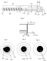
Figure 1 shows a side view of a first embodiment of a screw. -
Figure 2 shows a detail side view of the screw offigure 1 , showing details of the tipward taper zone of variable axial length. -
Figure 3 shows a side view of a second embodiment of a screw. -
Figure 4 shows a detail side view of the screw offigure 3 , showing details of the tipward taper zone of variable axial length. -
Figure 5 shows a side view of a third embodiment of a screw. -
Figure 6 shows a detail side view of the screw offigure 5 , showing details of the tipward taper zone of variable axial length. -
Figure 7 shows a cross sectional view C-C of the screw offigure 5 . -
Figure 8 shows a cross sectional view D-D of the screw offigure 5 . -
Figure 9 shows a cross sectional view F-F of the screw offigure 5 . -
Figure 10 shows a front view of a screw offigure 5 . -
Figure 11 shows a cross sectional view B-B of the screw offigure 10 . -
Figure 12 shows a cross sectional view A-A of the screw offigure 10 . - A first embodiment of a screw is shown in
figures 1 and 2 . The screw comprises anelongate shaft 10, which has atip 11 and arear end 18. Thetip 11 and therear end 18, respectively, are opposite regions of theshaft 10. Thetip 11 leads theshaft 10 and is intended to be inserted first into a hole when the screw is installed as intended. Alongitudinal axis 99 of theshaft 10 extents through theshaft 10, and through both thetip 11 and therear end 18. - The screw further comprises a
thread helix 40, which is attached to theshaft 10, and which winds around theshaft 10 and around thelongitudinal axis 99. In the present embodiment, theshaft 10 and thethread helix 40 are monolithic, by way of example. - The screw further comprises a
head 19, which is attached to theshaft 10 at therear end 18 of theshaft 10. In the present embodiment, thehead 19 is a hex head, by way of example. Alternatively, it could e.g. be a countersunk head, or another suitable head. In the present embodiment, theshaft 10 and thehead 19 are monolithic, by way of example. - The
shaft 10 has a threadedzone 12, which is that axially extending section of theshaft 10 where the thread helix 40 and theshaft 10 overlap axially. Theshaft 10 also has an unthreadedzone 14, which an axially extending section of theshaft 10 that is devoid of thread helixes. - The threaded
zone 12 and the unthreadedzone 14 are, axially, adjacent to one another. Thetip 11 is located closer to the threadedzone 12 than to the unthreadedzone 14. In particular, the threadedzone 12 includes thetip 11. However, in other embodiments, thetip 11 might also be axially distant from the threadedzone 12. The unthreadedzone 14 is located, axially, between the threadedzone 12 and thehead 19. The unthreadedzone 14 adjoins therear end 18 of theshaft 10. - The
shaft 10 has atipward taper zone 20 of variable axial length e20. Thiszone 20 has a tipward taper, which means that in thiszone 20, the surface of theshaft 10 converges towards thetip 11. Thiszone 20 furthermore has variable axial length e20, which means the length of thiszone 20, when considered in the direction of thelongitudinal axis 99, is not constant around thelongitudinal axis 99. In the present embodiment, the axial length e20 of thezone 20 has three length maxima and three length minima. - In the present embodiment, the
tipward taper zone 20 of variable axial length e20 adjoins the unthreadedzone 14, namely at the rearward end of thetipward taper zone 20. Thetipward taper zone 20 also adjoins the threadedzone 12, namely at the tipward end of thetipward taper zone 20. Thetipward taper zone 20 is thus located axially between the threadedzone 12 and the unthreadedzone 14. In the present embodiment, thethread helix 40 extends, at its rearward end region, into thetipward taper zone 20. However, generally, thethread helix 40 can also be axially distant from thetipward taper zone 20 of variable axial length e20. - The
tipward taper zone 20 of variable axial length e20 has generally constant axial distance r20 from therear end 18 of theshaft 10, which means that the axial distance r20 from therear end 18 of theshaft 10 does not change around thelongitudinal axis 99. In other words, thezone 20 has generally constant rearward reach. - Since the axial distance r20 of the
zone 20 from therear end 18 of theshaft 10 is generally constant, whereas the axial length e20 of thezone 20 is variable around thelongitudinal axis 99, the tipward reach of thiszone 20 is variable around thelongitudinal axis 99, i.e. the axial distance of thezone 20 from thetip 11 is variable around thelongitudinal axis 99. In particular, thezone 20 thus includes tabs that project towards thetip 11, wherein the number of tabs in particular corresponds to the number of length maxima of the axial length e20 of thezone 20. - In order to form this type of
zone 20, theshaft 10 may have generally circular cross section where it adjoins thezone 20 at the rearward end of thezone 20, and theshaft 10 may have generally non-circular, in particular tri-lobular cross section where it adjoins thezone 20 at the tipward end of thezone 20. - The
shaft 10 of the screw of the present embodiment moreover comprises atipward taper zone 22 of generally constant axial length and of generally constant axial distance from therear end 18 of theshaft 10. Thiszone 22 is located within the unthreadedzone 14, in particular axially distant from both the tipward end of the unthreadedzone 14 and from the rearward end of the unthreadedzone 14. - A second embodiment of a screw is shown in
figures 3 and 4 . The screw comprises anelongate shaft 110, which has atip 111 and arear end 118. Thetip 111 and therear end 118, respectively, are opposite regions of theshaft 110. Thetip 111 leads theshaft 110 and is intended to be inserted first into a hole when the screw is installed as intended. Alongitudinal axis 199 of theshaft 110 extents through theshaft 110, and through both thetip 111 and therear end 118. - The screw further comprises a
thread helix 140, which is attached to theshaft 110, and which winds around theshaft 110 and around thelongitudinal axis 199. In the present embodiment, theshaft 110 and thethread helix 140 are monolithic, by way of example. - The screw further comprises a
head 119, which is attached to theshaft 110 at therear end 118 of theshaft 110. In the present embodiment, thehead 119 is a hex head, by way of example. Alternatively, it could e.g. be a countersunk head, or another suitable head. In the present embodiment, theshaft 110 and thehead 119 are monolithic, by way of example. - The
shaft 110 has a threadedzone 112, which is that axially extending section of theshaft 110 where thethread helix 140 and theshaft 110 overlap axially. Theshaft 110 also has an unthreadedzone 114, which an axially extending section of theshaft 110 that is devoid of thread helixes. - The threaded
zone 112 and the unthreadedzone 114 are, axially, adjacent to one another. Thetip 111 is located closer to the threadedzone 112 than to the unthreadedzone 114. In particular, the threadedzone 112 includes thetip 111. However, in other embodiments, thetip 111 might also be axially distant from the threadedzone 112. The unthreadedzone 114 is located, axially, between the threadedzone 112 and thehead 119. The unthreadedzone 114 adjoins therear end 118 of theshaft 110. - The
shaft 110 has atipward taper zone 120 of variable axial length e120. Thiszone 120 has a tipward taper, which means that in thiszone 120, the surface of theshaft 110 converges towards thetip 111. Thiszone 120 furthermore has variable axial length e120, which means the length of thiszone 120, when considered in the direction of thelongitudinal axis 199, is not constant around thelongitudinal axis 199. In the present embodiment, the axial length e120 of thezone 120 has three length maxima and three length minima. - In the present embodiment, the
tipward taper zone 120 of variable axial length e120 is located within the unthreadedzone 114, right next to therear end 118 of theshaft 110. In particular, the rearward end of thezone 120 coincides with therear end 118 of theshaft 110. Thezone 20 thus adjoins thehead 119. - The
tipward taper zone 120 of variable axial length e120 has generally constant axial distance r120 from therear end 118 of theshaft 110, which means that the axial distance r120 from therear end 118 of theshaft 110 does not change around thelongitudinal axis 199. In other words, thezone 120 has generally constant rearward reach. In the present embodiment, this axial distance r120 is generally zero throughout. - Since the axial distance r120 of the
zone 120 from therear end 118 of theshaft 110 is generally constant, whereas the axial length e120 of thezone 120 is variable around thelongitudinal axis 199, the tipward reach of thiszone 120 is variable around thelongitudinal axis 199, i.e. the axial distance of thezone 120 from thetip 111 is variable around thelongitudinal axis 199. In particular, thezone 120 thus includes tabs that project towards thetip 111, wherein the number of tabs in particular corresponds to the number of length maxima of the axial length e120 of thezone 120. - In order to form this type of
zone 120, thehead 199 may have generally circular cross section where it adjoins thezone 120 at the rearward end of thezone 120, and theshaft 110 may have generally non-circular, in particular tri-lobular cross section where it adjoins thezone 120 at the tipward end of thezone 120. In particular, both the threadedzone 112 and the unthreadedzone 114 might have generally non-circular, in particular tri-lobular cross section. - The
shaft 110 of the screw of the present embodiment moreover comprises atipward taper zone 122 of generally constant axial length and of generally constant axial distance from therear end 118 of theshaft 110. Thiszone 122 is located within the unthreadedzone 114, in particular axially distant from both the tipward end of the unthreaded zone and from the rearward end of the unthreadedzone 114. Thezone 122 is located closer to thetip 11 than is thezone 120. - A third embodiment of a screw is shown in
figures 5 to 12 . The screw comprises anelongate shaft 210, which has atip 211 and arear end 218. Thetip 211 and therear end 218, respectively, are opposite regions of theshaft 210. Thetip 211 leads theshaft 210 and is intended to be inserted first into a hole when the screw is installed as intended. Alongitudinal axis 299 of theshaft 210 extents through theshaft 210, and through both thetip 211 and therear end 218. - The screw further comprises a
thread helix 240, which is attached to theshaft 210, and which winds around theshaft 210 and around thelongitudinal axis 299. In the present embodiment, theshaft 210 and thethread helix 240 are monolithic, by way of example. - The screw further comprises a
head 219, which is attached to theshaft 210 at therear end 218 of theshaft 210. In the present embodiment, thehead 219 is a hex head, by way of example. Alternatively, it could e.g. be a countersunk head, or another suitable head. In the present embodiment, theshaft 210 and thehead 219 are monolithic, by way of example. - The
shaft 210 has a threadedzone 212, which is that axially extending section of theshaft 210 where thethread helix 240 and theshaft 210 overlap axially. Theshaft 210 also has an unthreadedzone 214, which an axially extending section of theshaft 210 that is devoid of thread helixes. - The threaded
zone 212 and the unthreadedzone 214 are, axially, adjacent to one another. Thetip 211 is located closer to the threadedzone 212 than to the unthreadedzone 214. In particular, the threadedzone 212 includes thetip 211. However, in other embodiments, thetip 211 might also be axially distant from the threadedzone 212. The unthreadedzone 214 is located, axially, between the threadedzone 212 and thehead 219. The unthreadedzone 214 adjoins therear end 218 of theshaft 210. - The
shaft 210 has atipward taper zone 220 of variable axial length e220. Thiszone 220 has a tipward taper, which means that in thiszone 220, the surface of theshaft 210 converges towards thetip 211. Thiszone 220 furthermore has variable axial length e220, which means the length of thiszone 220, when considered in the direction of thelongitudinal axis 299, is not constant around thelongitudinal axis 299. In the present embodiment, the axial length e220 of thezone 220 has three length maxima and three length minima. - In the present embodiment, the
tipward taper zone 220 of variable axial length e220 is located within the unthreadedzone 214, in the axial middle thereof (i.e. at a distance both from the rearward end and from the tipward end of the unthreaded zone 214). - The
tipward taper zone 220 of variable axial length e220 has generally constant axial distance r220 from therear end 218 of theshaft 210, which means that the axial distance r220 from therear end 218 of theshaft 210 does not change around thelongitudinal axis 299. In other words, thezone 220 has generally constant rearward reach. In the present embodiment, this axial distance r220 is greater than the minimum axial length e220 of thezone 220, but in other embodiments, this might be different. - Since the axial distance r220 of the
zone 220 from therear end 218 of theshaft 210 is generally constant, whereas the axial length e220 of thezone 220 is variable around thelongitudinal axis 299, the tipward reach of thiszone 220 is variable around thelongitudinal axis 299, i.e. the axial distance of thezone 220 from thetip 211 is variable around thelongitudinal axis 299. In particular, thezone 220 thus includes tabs that project towards thetip 211, wherein the number of tabs in particular corresponds to the number of length maxima of the axial length e220 of thezone 220. - In order to form this type of
zone 220,shaft 210 may have generally circular cross section where it adjoins thezone 220 at the rearward end of the zone 220 (this generally circular cross section being shown infigure 9 ), and theshaft 210 may have generally non-circular, in particular tri-lobular cross section where it adjoins thezone 220 at the tipward end of the zone 220 (this generally non-circular cross section being shown infigure 8 ). In particular the unthreadedzone 214 might also have generally non-circular, in particular tri-lobular cross section (the generally non-circular cross section of the threadedzone 212 being shown infigure 7 ). This the shaft has generally non-circular, in particular tri-lobular cross section tipwardly of thezone 220, and generally circular cross section rearwardly of thiszone 220. - The
shaft 210 of the screw of the present embodiment moreover comprises atipward taper zone 222 of generally constant axial length and of generally constant axial distance from therear end 218 of theshaft 210. Thiszone 222 is located within the unthreadedzone 214, in particular axially distant from both the tipward end of the unthreaded zone and from the rearward end of the unthreadedzone 214. Thezone 222 is located closer to thetip 11 than is thezone 220. - The
thread helix 240 also might have generally non-circular, in particular tri-lobular outer shape. When thethread helix 240 is formed by rolling, afissure 244 might form within the thread helix 240 (namely where material that has been upset from opposite axial sides meets). When thethread helix 240 has generally non-circular, in particular tri-lobular outer shape, the depth D of thefissure 244 might vary. This might be since during rolling, pressure and amount of material flow might vary depending on where on the tri-lobular pattern the forming takes place.
Claims (8)
- Concrete screw comprisinga shaft (10, 110, 210), which has a tip (11, 111, 211), a rear end (18, 118, 218) and a longitudinal axis (99, 199, 299) that extends through the tip (11, 111, 211) and through the rear end (18, 118, 218), wherein the shaft (10, 110, 210) has a threaded zone (12, 112, 212) and an unthreaded zone (14, 114, 214) that is located axially adjacent to the threaded zone (12, 112, 212), wherein the threaded zone is located closer to the tip (11, 111, 211) than is the unthreaded zone (14, 114, 214),and a thread helix (40, 140, 240) that is attached to the shaft (10, 110, 210) in the threaded zone (12, 112, 212) of the shaft (10, 110, 210), characterized in that- the shaft (10, 110, 210) has a tipward taper zone (20, 120, 220) of variable axial length (e20, e120, e220).
- Concrete screw according to claim 1,
characterized in that
the tipward taper zone (120, 220) of variable axial length (e120, e220) is located within the unthreaded zone (114, 214). - Concrete screw according to claim 1,
characterized in that
the tipward taper zone (20) of variable axial length (e20) adjoins the unthreaded zone (14). - Concrete screw according to claim 3,
characterized in that
the thread helix (40) extends into the tipward taper zone (20) of variable axial length (e20). - Concrete screw according to any of the preceding claims,
characterized in that
the concrete screw has a head (19, 119, 219) that is attached to the shaft (10, 110, 210) at the rear end (18, 118, 218) of the shaft (10, 110, 210). - Concrete screw according to claim 5,
characterized in that
the tipward taper zone (120) of variable axial length (e120) adjoins the head (119). - Concrete screw according to any of the preceding claims,
characterized in that
the axial length (e20, e120, e220) of the tipward taper zone (20, 120, 220) of variable axial length (e20, e120, e220) has at least two maxima. - Concrete screw according to any of the preceding claims,
characterized in that
the tipward taper zone (20, 120, 220) of variable axial length (e20, e120, e220) has generally constant axial distance (r20, r120, r220) from the rear end (18, 118, 218) of the shaft (10, 110, 210).
Priority Applications (2)
| Application Number | Priority Date | Filing Date | Title |
|---|---|---|---|
| EP23211441.3A EP4560154A1 (en) | 2023-11-22 | 2023-11-22 | Tipward taper zone of variable axial length |
| PCT/EP2024/081611 WO2025108725A1 (en) | 2023-11-22 | 2024-11-08 | Tipward taper zone of variable axial length |
Applications Claiming Priority (1)
| Application Number | Priority Date | Filing Date | Title |
|---|---|---|---|
| EP23211441.3A EP4560154A1 (en) | 2023-11-22 | 2023-11-22 | Tipward taper zone of variable axial length |
Publications (1)
| Publication Number | Publication Date |
|---|---|
| EP4560154A1 true EP4560154A1 (en) | 2025-05-28 |
Family
ID=88969726
Family Applications (1)
| Application Number | Title | Priority Date | Filing Date |
|---|---|---|---|
| EP23211441.3A Withdrawn EP4560154A1 (en) | 2023-11-22 | 2023-11-22 | Tipward taper zone of variable axial length |
Country Status (2)
| Country | Link |
|---|---|
| EP (1) | EP4560154A1 (en) |
| WO (1) | WO2025108725A1 (en) |
Citations (10)
| Publication number | Priority date | Publication date | Assignee | Title |
|---|---|---|---|---|
| US3681963A (en) | 1970-01-19 | 1972-08-08 | Res Eng & Mfg | Self-thread forming threaded fasteners and method and apparatus for making the same |
| US3902399A (en) * | 1970-02-03 | 1975-09-02 | Vincent Yotti | Concrete screw |
| EP0139195B1 (en) | 1983-09-09 | 1988-04-20 | Conti Fasteners AG | Method of making screws and dies therefor |
| US6089806A (en) | 1999-01-25 | 2000-07-18 | Conti Fasteners | Blank for self-tapping fastener |
| EP0930437B1 (en) * | 1998-01-15 | 2001-08-29 | TOGE-Dübel A. Gerhard KG | Thread tapping screw |
| EP1188938A1 (en) | 2000-09-13 | 2002-03-20 | TOGE-Dübel A. Gerhard KG | Thread forming screw, especially a concrete screw |
| EP1207312A2 (en) | 2000-11-20 | 2002-05-22 | Celo Distribucion, S.A. | Screw for wood and similar materials |
| US20160001348A1 (en) | 2013-02-26 | 2016-01-07 | Hilti Aktiengesellschaft | Method for Producing Screws and Concrete Screw |
| US20160003284A1 (en) | 2013-02-26 | 2016-01-07 | Hilti Aktiengesellschaft | Concrete Screw |
| DE102021211692A1 (en) * | 2021-10-15 | 2023-04-20 | Toge Dübel Gmbh & Co. Kg | Self tapping screw |
-
2023
- 2023-11-22 EP EP23211441.3A patent/EP4560154A1/en not_active Withdrawn
-
2024
- 2024-11-08 WO PCT/EP2024/081611 patent/WO2025108725A1/en active Pending
Patent Citations (10)
| Publication number | Priority date | Publication date | Assignee | Title |
|---|---|---|---|---|
| US3681963A (en) | 1970-01-19 | 1972-08-08 | Res Eng & Mfg | Self-thread forming threaded fasteners and method and apparatus for making the same |
| US3902399A (en) * | 1970-02-03 | 1975-09-02 | Vincent Yotti | Concrete screw |
| EP0139195B1 (en) | 1983-09-09 | 1988-04-20 | Conti Fasteners AG | Method of making screws and dies therefor |
| EP0930437B1 (en) * | 1998-01-15 | 2001-08-29 | TOGE-Dübel A. Gerhard KG | Thread tapping screw |
| US6089806A (en) | 1999-01-25 | 2000-07-18 | Conti Fasteners | Blank for self-tapping fastener |
| EP1188938A1 (en) | 2000-09-13 | 2002-03-20 | TOGE-Dübel A. Gerhard KG | Thread forming screw, especially a concrete screw |
| EP1207312A2 (en) | 2000-11-20 | 2002-05-22 | Celo Distribucion, S.A. | Screw for wood and similar materials |
| US20160001348A1 (en) | 2013-02-26 | 2016-01-07 | Hilti Aktiengesellschaft | Method for Producing Screws and Concrete Screw |
| US20160003284A1 (en) | 2013-02-26 | 2016-01-07 | Hilti Aktiengesellschaft | Concrete Screw |
| DE102021211692A1 (en) * | 2021-10-15 | 2023-04-20 | Toge Dübel Gmbh & Co. Kg | Self tapping screw |
Also Published As
| Publication number | Publication date |
|---|---|
| WO2025108725A1 (en) | 2025-05-30 |
Similar Documents
| Publication | Publication Date | Title |
|---|---|---|
| EP2030713B1 (en) | Radius end mill | |
| EP2322303B1 (en) | Drill | |
| US4527932A (en) | Self-tapping screw | |
| US6328516B1 (en) | Screw with cutting edge | |
| JP5651605B2 (en) | Rotary cutting tool with chip breaker pattern | |
| US6739815B2 (en) | Wood screw | |
| CA3072757C (en) | Sheet metal screw | |
| PL192007B1 (en) | Self-tapping screw | |
| EP0579816A4 (en) | ||
| CN1225710A (en) | Self-tapping screw, in particular concrete screw | |
| US7150588B2 (en) | Thread forming tap with a non-circular cross-section and radially extending cutting edges | |
| GB1569066A (en) | Thread forming screw with step taper and dies for making the same | |
| KR20010040563A (en) | Self-tapping screw | |
| EP3150315B1 (en) | Mill | |
| US20010027693A1 (en) | Nut unit | |
| US20230392636A1 (en) | Concrete fastener | |
| US20090155018A1 (en) | Thread-tapping screw | |
| CN105008730A (en) | Concrete screw | |
| WO2025108725A1 (en) | Tipward taper zone of variable axial length | |
| KR20060051836A (en) | Thread cutting tools | |
| EP3810942B1 (en) | Self-tapping screw | |
| EP3150314B1 (en) | Mill | |
| US9718136B2 (en) | Drill | |
| EP4074990A1 (en) | Expansion anchor | |
| EP4215765A1 (en) | Screw with subducting screw thread element |
Legal Events
| Date | Code | Title | Description |
|---|---|---|---|
| PUAI | Public reference made under article 153(3) epc to a published international application that has entered the european phase |
Free format text: ORIGINAL CODE: 0009012 |
|
| STAA | Information on the status of an ep patent application or granted ep patent |
Free format text: STATUS: THE APPLICATION HAS BEEN PUBLISHED |
|
| AK | Designated contracting states |
Kind code of ref document: A1 Designated state(s): AL AT BE BG CH CY CZ DE DK EE ES FI FR GB GR HR HU IE IS IT LI LT LU LV MC ME MK MT NL NO PL PT RO RS SE SI SK SM TR |
|
| STAA | Information on the status of an ep patent application or granted ep patent |
Free format text: STATUS: THE APPLICATION IS DEEMED TO BE WITHDRAWN |
|
| 18D | Application deemed to be withdrawn |
Effective date: 20251129 |