EP4560125A1 - Exhaust purification system for internal combustion engine - Google Patents
Exhaust purification system for internal combustion engine Download PDFInfo
- Publication number
- EP4560125A1 EP4560125A1 EP24212015.2A EP24212015A EP4560125A1 EP 4560125 A1 EP4560125 A1 EP 4560125A1 EP 24212015 A EP24212015 A EP 24212015A EP 4560125 A1 EP4560125 A1 EP 4560125A1
- Authority
- EP
- European Patent Office
- Prior art keywords
- filter
- differential pressure
- amount
- internal combustion
- combustion engine
- Prior art date
- Legal status (The legal status is an assumption and is not a legal conclusion. Google has not performed a legal analysis and makes no representation as to the accuracy of the status listed.)
- Pending
Links
Images





Classifications
-
- F—MECHANICAL ENGINEERING; LIGHTING; HEATING; WEAPONS; BLASTING
- F01—MACHINES OR ENGINES IN GENERAL; ENGINE PLANTS IN GENERAL; STEAM ENGINES
- F01N—GAS-FLOW SILENCERS OR EXHAUST APPARATUS FOR MACHINES OR ENGINES IN GENERAL; GAS-FLOW SILENCERS OR EXHAUST APPARATUS FOR INTERNAL-COMBUSTION ENGINES
- F01N3/00—Exhaust or silencing apparatus having means for purifying, rendering innocuous, or otherwise treating exhaust
- F01N3/02—Exhaust or silencing apparatus having means for purifying, rendering innocuous, or otherwise treating exhaust for cooling, or for removing solid constituents of, exhaust
- F01N3/021—Exhaust or silencing apparatus having means for purifying, rendering innocuous, or otherwise treating exhaust for cooling, or for removing solid constituents of, exhaust by means of filters
- F01N3/023—Exhaust or silencing apparatus having means for purifying, rendering innocuous, or otherwise treating exhaust for cooling, or for removing solid constituents of, exhaust by means of filters using means for regenerating the filters, e.g. by burning trapped particles
-
- F—MECHANICAL ENGINEERING; LIGHTING; HEATING; WEAPONS; BLASTING
- F01—MACHINES OR ENGINES IN GENERAL; ENGINE PLANTS IN GENERAL; STEAM ENGINES
- F01N—GAS-FLOW SILENCERS OR EXHAUST APPARATUS FOR MACHINES OR ENGINES IN GENERAL; GAS-FLOW SILENCERS OR EXHAUST APPARATUS FOR INTERNAL-COMBUSTION ENGINES
- F01N9/00—Electrical control of exhaust gas treating apparatus
- F01N9/002—Electrical control of exhaust gas treating apparatus of filter regeneration
-
- F—MECHANICAL ENGINEERING; LIGHTING; HEATING; WEAPONS; BLASTING
- F01—MACHINES OR ENGINES IN GENERAL; ENGINE PLANTS IN GENERAL; STEAM ENGINES
- F01N—GAS-FLOW SILENCERS OR EXHAUST APPARATUS FOR MACHINES OR ENGINES IN GENERAL; GAS-FLOW SILENCERS OR EXHAUST APPARATUS FOR INTERNAL-COMBUSTION ENGINES
- F01N2560/00—Exhaust systems with means for detecting or measuring exhaust gas components or characteristics
- F01N2560/08—Exhaust systems with means for detecting or measuring exhaust gas components or characteristics the means being a pressure sensor
-
- F—MECHANICAL ENGINEERING; LIGHTING; HEATING; WEAPONS; BLASTING
- F01—MACHINES OR ENGINES IN GENERAL; ENGINE PLANTS IN GENERAL; STEAM ENGINES
- F01N—GAS-FLOW SILENCERS OR EXHAUST APPARATUS FOR MACHINES OR ENGINES IN GENERAL; GAS-FLOW SILENCERS OR EXHAUST APPARATUS FOR INTERNAL-COMBUSTION ENGINES
- F01N2560/00—Exhaust systems with means for detecting or measuring exhaust gas components or characteristics
- F01N2560/14—Exhaust systems with means for detecting or measuring exhaust gas components or characteristics having more than one sensor of one kind
-
- F—MECHANICAL ENGINEERING; LIGHTING; HEATING; WEAPONS; BLASTING
- F01—MACHINES OR ENGINES IN GENERAL; ENGINE PLANTS IN GENERAL; STEAM ENGINES
- F01N—GAS-FLOW SILENCERS OR EXHAUST APPARATUS FOR MACHINES OR ENGINES IN GENERAL; GAS-FLOW SILENCERS OR EXHAUST APPARATUS FOR INTERNAL-COMBUSTION ENGINES
- F01N2900/00—Details of electrical control or of the monitoring of the exhaust gas treating apparatus
- F01N2900/04—Methods of control or diagnosing
- F01N2900/0402—Methods of control or diagnosing using adaptive learning
-
- F—MECHANICAL ENGINEERING; LIGHTING; HEATING; WEAPONS; BLASTING
- F01—MACHINES OR ENGINES IN GENERAL; ENGINE PLANTS IN GENERAL; STEAM ENGINES
- F01N—GAS-FLOW SILENCERS OR EXHAUST APPARATUS FOR MACHINES OR ENGINES IN GENERAL; GAS-FLOW SILENCERS OR EXHAUST APPARATUS FOR INTERNAL-COMBUSTION ENGINES
- F01N2900/00—Details of electrical control or of the monitoring of the exhaust gas treating apparatus
- F01N2900/06—Parameters used for exhaust control or diagnosing
- F01N2900/08—Parameters used for exhaust control or diagnosing said parameters being related to the engine
-
- F—MECHANICAL ENGINEERING; LIGHTING; HEATING; WEAPONS; BLASTING
- F01—MACHINES OR ENGINES IN GENERAL; ENGINE PLANTS IN GENERAL; STEAM ENGINES
- F01N—GAS-FLOW SILENCERS OR EXHAUST APPARATUS FOR MACHINES OR ENGINES IN GENERAL; GAS-FLOW SILENCERS OR EXHAUST APPARATUS FOR INTERNAL-COMBUSTION ENGINES
- F01N2900/00—Details of electrical control or of the monitoring of the exhaust gas treating apparatus
- F01N2900/06—Parameters used for exhaust control or diagnosing
- F01N2900/16—Parameters used for exhaust control or diagnosing said parameters being related to the exhaust apparatus, e.g. particulate filter or catalyst
- F01N2900/1606—Particle filter loading or soot amount
Definitions
- the present invention relates to an exhaust purification system for an internal combustion engine.
- a vehicle equipped with a diesel engine as an internal combustion engine collects micro particulate matters (PM) in an exhaust gas by a filter (diesel particulate filter (DPF)) provided in an exhaust passage so as not to release the particulate matters to the atmosphere.
- the filter has a wall provided with a large number of micropores that do not allow the particulate matters to pass therethrough, and the exhaust gas is passed through the micropores of the wall so that the particulate matters are collected.
- filter regeneration processing of burning and removing the particulate matters deposited in the filter is periodically performed.
- the temperature of the exhaust gas of about 300 to 400 [°C] is forcibly raised to about 600 [°C] or more in a normal operation state, and the particulate matters deposited in the filter is burned and removed.
- the temperature of the exhaust gas is forcibly raised, fuel is added to the exhaust gas, and the fuel is reacted with an oxidation catalyst disposed on the upstream side of the filter to raise the temperature of the exhaust gas, and therefore the fuel is consumed.
- Execution of the filter regeneration processing is not preferable when the frequency is more than necessary because the fuel efficiency deteriorates, and is not preferable when the frequency is less than necessary because the filter may be clogged. Therefore, it is necessary to perform the filter regeneration processing at an appropriate frequency, and thus it is necessary to accurately detect the deposition amount of the particulate matters in the filter.
- the deposition amount of the particulate matters in the filter cannot be directly detected, and as methods of estimating the deposition amount, the following methods (1) and (2) are generally used.
- An integration type estimation method of estimating the deposition amount of particulate matters by measuring and mapping a generation amount of the particulate matters in accordance with the operation state of the internal combustion engine using an actual vehicle, and obtaining and integrating the generation amount in accordance with the operation state at a predetermined time interval.
- the integration type estimation method of (1) described above is not preferable because an error due to variation, deterioration, and the like of the internal combustion engine is relatively large, and the estimation accuracy is lower than that of the differential pressure type estimation method of (2).
- the differential pressure type estimation method of (2) described above there is a case where the differential pressure across the filter deviates to a higher side or a lower side with respect to a reference differential pressure in relation to the deposition amount of the particulate matters. Therefore, it is desired to appropriately correct the detected differential pressure across the filter.
- the particulate matters depositing in the filter includes particulate matters (micropore deposition particulate matter) that has entered micropores in a wall of the filter and particulate matters (wall surface deposition particulate matter) that deposits on the surface of the wall of the filter.
- the exhaust gas hardly passes through the filter depending on the amount of the micropore deposition particulate matters (see FIG. 6 ), and the particulate matters deviates to a side where the differential pressure across the filter is high.
- the particulate matters In a filter in which particulate matters do not deposit immediately after completion of the filter regeneration processing, the particulate matters (micropore deposition particulate matter) first enter the micropores in the wall of the filter until reaching a saturation state (micropore deposition initial amount), and then the particulate matters (wall surface deposition particulate matter) deposits on the wall surface of the filter. As the particulate matters deposit on the wall surface of the filter, the particulate matters cannot enter the micropores in the wall of the filter, and therefore the micropore deposition particulate matters does not increase in amount from the micropore deposition initial amount.
- the micropore deposition particulate matters are gradually burned and reduced depending on the operation state of the internal combustion engine, and the deviation to the higher side of the differential pressure across the filter gradually decreases. That is, the deviation amount to the higher side of the differential pressure across the filter is large at an initial stage, and then the deviation amount gradually decreases (see a characteristic B deviated to a higher side with respect to a reference characteristic A illustrated in FIG. 8 ).
- a deviation (error) to a lower side with respect to a reference characteristic of the differential pressure across the filter is generated due to a phenomenon described below.
- a crack or the like is generated in a layer of the particulate matters (wall surface deposition particulate matter) deposited on the wall surface of the filter based on the operation state of the internal combustion engine, the exhaust gas easily passes in accordance with the amount of the crack or the like (see FIG. 7 ), and the differential pressure across the filter deviates to a lower side.
- the filter regeneration processing is performed and the particulate matters (wall surface deposition particulate matter) deposits on the surface of the wall of the filter, a cleavage, a crack, and the like may be generated depending on the operation state of the internal combustion engine.
- the deviation to the lower side of the differential pressure across the filter gradually increases. That is, regarding the deviation to the lower side of the differential pressure across the filter, the first deviation amount is small, and then the deviation amount gradually increases (see a characteristic C deviated to a lower side with respect to the reference characteristic A illustrated in FIG. 8 ).
- Japanese Patent Application Publication No. 2007-170193 discloses an exhaust purification device that corrects a differential pressure across the filter deviated to a higher side with respect to a reference characteristic by a micropore deposition particulate matters to further improve the estimation accuracy of the deposition amount of particulate matters in the filter.
- a micropore deposition initial amount is first obtained, thereafter, a burned amount of the micropore deposition particulate matters in accordance with an operation state is obtained, and the differential pressure across the filter is corrected based on a remaining amount in which the burned amount is subtracted from the micropore deposition initial amount.
- the deposition amount of particulate matters is first estimated by a differential pressure type estimation method. Thereafter, when a deterioration determination index of the estimation accuracy in which the differential pressure across the filter deviates to a lower side with respect to a reference characteristic due to a cleavage generated in a wall surface deposition particulate matters exceeds a threshold, the estimation method of the deposition amount of the particulate matters is switched from the differential pressure type estimation method to the integration type estimation method. However, the differential pressure across the filter deviated to the lower side is not corrected.
- the deposition of the particulate matters (micropore deposition particulate matter) in the micropores of the wall of the filter, the burning of the micropore deposition particulate matters, and generation of a cleavage, a crack, and the like of the wall surface deposition particulate matters vary depending on the operation state of the internal combustion engine, and only one or both may occur. That is, depending on the operation state of the internal combustion engine, the differential pressure across the filter may deviate to a higher side or greatly deviate to a lower side with respect to the reference characteristic.
- the invention described in Japanese Patent Application Publication No. 2007-170193 copes with a deviation to the higher side of the differential pressure across the filter due to deposition and burning of the particulate matters (micropore deposition particulate matter) in the micropores of the wall of the filter.
- the particulate matters micropore deposition particulate matter
- generation of a cleavage, a crack, and the like of the wall surface deposition particulate matters is not taken into consideration, it is not possible to cope with the deviation to the lower side of the differential pressure across the filter, and the estimation accuracy of the deposition amount of the particulate matters may be lowered.
- the estimation accuracy may significantly decrease.
- the invention described in Japanese Patent Application Publication No. 2010-190120 copes with deviation to the lower side of the differential pressure across the filter due to a cleavage or a crack of the wall surface deposition particulate matters.
- the invention described in Japanese Patent Application Publication No. 2010-190120 switches the estimation method of the deposition amount of the particulate matters from the differential pressure type estimation method to the integration type estimation method, but does not correct the differential pressure across the filter. Since deposition and burning of the particulate matters (micropore deposition particulate matter) in the micropores of the wall of the filter are not taken into consideration, it is not possible to cope with the deviation to the higher side of the differential pressure across the filter.
- the present invention which has been made in light of the above-mentioned problem, is directed to providing an exhaust purification system for an internal combustion engine wherein the exhaust purification system can further improve the estimation accuracy by appropriately correcting the differential pressure across the filter when estimating the deposition amount of the particulate matters in the filter based on the differential pressure across the filter.
- an exhaust purification system for an internal combustion engine including: a filter that is disposed in an exhaust passage of the internal combustion engine and collects a particulate matter contained in an exhaust gas from the internal combustion engine; a differential pressure detection device that detects a differential pressure across the filter, the differential pressure being a pressure difference of the exhaust gas between an inflow side and an outflow side of the filter; and a control device that detects an operation state of the internal combustion engine and controls the internal combustion engine based on the operation state that is detected.
- the control device executes filter regeneration processing of burning and removing the particulate matter deposited in the filter when determining that the particulate matter exceeding a predetermined amount deposits in the filter and a predetermined condition is satisfied, obtains, based on the operation state, an increase side correction amount by which the differential pressure across the filter detected using the differential pressure detection device is corrected to an increase side, obtains a corrected differential pressure in which the differential pressure across the filter is corrected using the increase side correction amount, and determines that the particulate matter exceeding the predetermined amount deposits in the filter when the corrected differential pressure exceeds a predetermined threshold set in accordance with the predetermined amount.
- an exhaust purification system for an internal combustion engine including: a filter that is disposed in an exhaust passage of the internal combustion engine and collects a particulate matter contained in an exhaust gas from the internal combustion engine; a differential pressure detection device that detects a differential pressure across the filter, the differential pressure being a pressure difference of the exhaust gas between an inflow side and an outflow side of the filter; and a control device that detects an operation state of the internal combustion engine and controls the internal combustion engine based on the operation state that is detected.
- the control device executes filter regeneration processing of burning and removing the particulate matter deposited in the filter when determining that the particulate matter exceeding a predetermined amount deposits in the filter and a predetermined condition is satisfied, obtains, based on the operation state, both an increase side correction amount by which the differential pressure across the filter detected using the differential pressure detection device is corrected to an increase side and a decrease side correction amount by which the differential pressure across the filter is corrected to a decrease side, obtains a corrected differential pressure in which the differential pressure across the filter is corrected using both the increase side correction amount and the decrease side correction amount, and determines that the particulate matter exceeding the predetermined amount deposits in the filter when the corrected differential pressure exceeds a predetermined threshold set in accordance with the predetermined amount.
- an internal combustion engine system 1 including an exhaust purification system 2 of the present invention will be described with reference to the drawings.
- An internal combustion engine 10 of the internal combustion engine system 1 in the example of FIG. 1 is what is called a diesel engine.
- the exhaust purification system 2 includes a control device 50, a filter 43 (particulate matter collection filter), and a differential pressure detection device 35.
- the configuration and the like of the internal combustion engine system 1 will be described in order from an intake side to an exhaust side.
- An intake pipe 11A is provided with an air flow rate detection device 31.
- the air flow rate detection device 31 e.g., an intake flow rate sensor
- the air flow rate detection device 31 outputs, to the control device 50, a detection signal corresponding to a flow rate [g/sec] of air sucked by the internal combustion engine 10.
- the air flow rate detection device 31 is provided with an intake temperature detection device 32A and an atmospheric pressure detection device 33A.
- the intake temperature detection device 32A e.g., an intake temperature sensor
- the atmospheric pressure detection device 33A e.g., a pressure sensor
- the intake pipe 11A is connected to a compressor 82 of a supercharger 80.
- the intake pipe 11A is connected to an inflow side of the compressor 82, and an intake pipe 11C is connected to a discharge side of the compressor 82.
- the compressor 82 is rotationally driven by a turbine 81, and pumps, to the intake pipe 11C, the intake air flowing in from the intake pipe 11A.
- the intake pipe 11A on an upstream side of the compressor 82 is provided with a pressure detection device 33B.
- the pressure detection device 33B (e.g., a pressure sensor) outputs, to the control device 50, a detection signal corresponding to the pressure of the air before being compressed by the compressor 82.
- a downstream side of the intake pipe 11C is connected to an intake manifold 11D.
- the intake pipe 11C is provided with a pressure detection device 33C, an intercooler 84, a throttle device 64, and an intake temperature detection device 32B.
- the pressure detection device 33C (e.g., a pressure sensor) outputs, to the control device 50, a detection signal corresponding to the pressure of the intake air pumped by the compressor 82.
- the intercooler 84 lowers the temperature of the intake air pumped from the compressor 82 to increase the oxygen density.
- the throttle device 64 adjusts the opening of a throttle valve to a target throttle opening based on a control signal from the control device 50.
- the intake temperature detection device 32B (e.g., an intake temperature sensor) outputs, to the control device 50, a detection signal corresponding to the temperature of the intake air lowered by the intercooler 84.
- a downstream side of the intake manifold 11D is connected to an intake port guiding the intake air to each cylinder of the internal combustion engine 10.
- the intake air guided to the intake manifold 11D is sucked into each cylinder of the internal combustion engine 10 and used for burning together with a fuel injected from an injector 21.
- the intake manifold 11D is provided with a pressure detection device 33D.
- the pressure detection device 33D e.g., a pressure sensor
- the internal combustion engine 10 is provided with a rotation detection device 34A and a cylinder detection device 34B.
- the rotation detection device 34A e.g., a rotation sensor of a crankshaft
- the cylinder detection device 34B outputs, to the control device 50, a detection signal (cylinder determination signal) when a piston of the first cylinder reaches a compression top dead center, for example.
- the internal combustion engine 10 is provided with a load device 63 that can adjust a load of the internal combustion engine 10.
- the load device 63 is, for example, an alternator, and changes the load of the internal combustion engine 10 based on a load control signal (power generation control signal) from the control device 50.
- the internal combustion engine 10 is provided with a coolant temperature detection device 32C.
- the coolant temperature detection device 32C e.g., a water temperature sensor
- An accelerator depression amount detection device 38 (e.g., an accelerator depression amount sensor) outputs, to the control device 50, a detection signal corresponding to a depression amount of an accelerator pedal operated by an operator.
- An ignition switch 39 is an input device for an instruction to start or stop the internal combustion engine from the operator.
- the control device 50 calculates a required load based on the rotation speed of the internal combustion engine based on the detection signal from the rotation detection device 34A and the depression amount of the accelerator pedal based on the detection signal from the accelerator depression amount detection device 38, and calculates a fuel amount in accordance with the required load. Then, based on the detection signals from the rotation detection device 34A and the cylinder detection device 34B, the control device 50 controls the injector 21 at a predetermined timing, and injects a fuel amount in accordance with the required load into each cylinder of a #1 cylinder to a #4 cylinder of the internal combustion engine 10.
- An exhaust manifold 12A is connected to an exhaust port of the internal combustion engine 10.
- the exhaust gas from the internal combustion engine 10 is guided to the exhaust manifold 12A, an exhaust pipe 12B, and the turbine 81 of the supercharger 80, rotationally drives the turbine 81, and is discharged to an exhaust pipe 12C.
- the exhaust gas from the internal combustion engine 10 contains carbon monoxide (CO), hydrocarbon (HC), particulate matters (PM), nitrogen oxide (NOx), and the like.
- An inflow side of an EGR pipe 13 for returning part of the exhaust gas to the intake air is connected to the exhaust manifold 12A or the exhaust pipe 12B.
- An outflow side of the EGR pipe 13 is connected to the intake pipe 11C or the intake manifold 11D.
- the EGR pipe 13 is provided with an EGR valve 13A controlled by the control device 50 to adjust the opening of the EGR pipe.
- the exhaust pipe 12B is connected to an outflow side of the exhaust manifold 12A.
- An inflow side of the turbine 81 of the supercharger 80 is connected to a downstream side of the exhaust pipe 12B.
- the exhaust pipe 12C is connected to an outflow side of the turbine 81, and an exhaust purification device 40 is connected to a downstream side of the exhaust pipe 12C.
- the exhaust purification device 40 includes an upstream side exhaust purification device 41 and a downstream side exhaust purification device 45 disposed downstream of the upstream side exhaust purification device 41.
- the upstream side exhaust purification device 41 includes a first oxidation catalyst 42 (diesel oxidation catalyst: DOC) and a filter 43 (diesel particulate filter: DPF) from the upstream side.
- the downstream side exhaust purification device 45 includes a urea SCR 46 (selective catalytic reduction: SCR, SCR catalyst) and a second oxidation catalyst 47 (diesel oxidation catalyst: DOC) from the upstream side.
- the first oxidation catalyst 42 causes an oxidation reaction of and purifies carbon monoxide (CO), hydrocarbon (HC), and the like contained in the exhaust gas.
- the filter 43 collects particulate matters (PM) contained in the exhaust gas and allows only the exhaust gas to flow out to the downstream side.
- the filter 43 also has a function of causing an oxidation reaction of and purifying carbon monoxide and hydrocarbon.
- the exhaust pipe 12C on the upstream side of the first oxidation catalyst 42 is provided with a fuel addition valve 61A, an exhaust temperature detection device 36A (e.g., an exhaust temperature sensor), and the like.
- the fuel addition valve 61A can add (inject) fuel, and injects, into the exhaust pipe 12C, fuel (reaction liquid) for raising the temperature of the exhaust gas by causing an oxidation reaction in the first oxidation catalyst 42 when executing filter regeneration processing of regenerating the filter 43 in which the collected particulate matters is deposited (when burning and removing the particulate matters).
- a dispersion device 61B that collides and disperses the fuel injected from the fuel addition valve 61A is disposed in the exhaust pipe 12C.
- the fuel addition valve 61A is supplied with fuel from a fuel tank 90.
- the downstream side of the first oxidation catalyst 42 as well as the upstream side of the filter 43 is provided with an exhaust temperature detection device 36B (e.g., an exhaust temperature sensor).
- the downstream side of the filter 43 is provided with an exhaust temperature detection device 36C (e.g., an exhaust temperature sensor).
- the exhaust temperature detection devices 36A, 36B, and 36C output, to the control device 50, detection signals corresponding to the temperature of the exhaust gas.
- the differential pressure detection device 35 (e.g., a differential pressure sensor) that detects a differential pressure (pressure difference) between the exhaust pressure on the downstream side of the first oxidation catalyst 42 as well as the upstream side of the filter 43 and the exhaust pressure on the downstream side of the filter 43.
- the differential pressure detection device 35 outputs, to the control device 50, a detection signal corresponding to a differential pressure across the filter, which is a pressure difference between the pressure on the upstream side and the pressure on the downstream side of the filter 43.
- the downstream side exhaust purification device 45 is provided with a urea water addition valve 62A, a dispersion device 62B, the urea SCR 46, the second oxidation catalyst 47, and the like from the upstream side.
- the urea SCR 46 is coupled to the downstream side of the filter 43 via an exhaust pipe 12D.
- the urea water addition valve 62A can add (inject) urea water, is disposed in the exhaust pipe 12D on the downstream side of the filter 43 as well as the upstream side of the urea SCR 46, and injects urea water (reaction liquid) into the exhaust gas at a predetermined timing.
- the injected urea water collides with and scatters to be atomized by the dispersion device 62B, diffuses in the exhaust pipe 12D, and reaches the urea SCR 46.
- the urea water addition valve 62A is supplied with urea water from a urea water tank not illustrated. Using ammonia gas generated from the added urea water, the urea SCR 46 reduces and purifies nitrogen oxides (NOx) contained in the exhaust gas.
- NOx nitrogen oxides
- the exhaust pipe 12D on the upstream side of the urea SCR 46 is provided with an NOx detection device 37A (e.g., an NOx sensor).
- An exhaust pipe 12E on the downstream side of the urea SCR 46 is provided with an NOx detection device 37B (e.g., an NOx sensor) and an exhaust temperature detection device 36D (e.g., an exhaust temperature sensor).
- the NOx detection devices 37A and 37B output, to the control device 50, detection signals corresponding to the concentration of NOx in the exhaust gas, and the exhaust temperature detection device 36D outputs, to the control device 50, detection signals corresponding to the temperature of the exhaust gas.
- the control device 50 calculates an NOx purification rate of the urea SCR 46 based on the detection signals of the NOx detection devices 37A and 37B and the exhaust temperature detection device 36D, and controls the urea water addition valve 62A based on the calculated NOx purification rate.
- the exhaust pipes 12B, 12C, 12D, and 12E correspond to exhaust passages.
- the second oxidation catalyst 47 is coupled to the downstream side of the urea SCR 46 via the exhaust pipe 12E.
- the second oxidation catalyst 47 oxidizes and purifies the ammonia gas remaining in the exhaust gas.
- the second oxidation catalyst 47 also has a function of causing an oxidation reaction of and purifying carbon monoxide and hydrocarbon.
- the control device 50 is a known device including a CPU 51, a RAM 52, a ROM 53 (storage device), a timer 54, and a nonvolatile storage device 55 (e.g., an EEPROM).
- the CPU 51 executes various arithmetic processing based on various programs and maps stored in the ROM 53 (e.g., a Flash-ROM).
- the RAM 52 temporarily stores an arithmetic result in the CPU, data input from each detection device, and the like, and the nonvolatile storage device 55 stores data to be saved, for example, when the internal combustion engine 10 is stopped.
- control device 50 can detect the operation state of the internal combustion engine 10 based on the detection signal that is input. In response to a request from the operator based on the operation state of the internal combustion engine 10 that is detected and a detection signal from the accelerator depression amount detection device 38, the control device 50 outputs a control signal for controlling various actuators such as the injector 21 that injects fuel into the cylinder, the fuel addition valve 61A, the urea water addition valve 62A, and the EGR valve 13A.
- the control device 50 can detect a differential pressure across the filter, which is a pressure difference between the upstream side and the downstream side of the filter 43, based on the detection signal from the differential pressure detection device 35, and can estimate the deposition amount of the particulate matters collected in the filter 43 based on the detected differential pressure across the filter. Then, when the estimation deposition amount exceeds a threshold, the control device 50 executes the filter regeneration processing to inject fuel (reaction liquid) from the fuel addition valve 61A to raise the exhaust temperature, and burns and removes the particulate matters deposited in the filter 43 to regenerate the filter 43.
- fuel reaction liquid
- the filter regeneration processing described above consumes fuel, fuel efficiency may deteriorate if the filter regeneration processing is executed at a frequency more than necessary, and the filter 43 may be clogged if the frequency is low.
- the filter regeneration processing it is necessary to accurately estimate the deposition amount of the particulate matters deposited in the filter 43.
- the differential pressure across the filter based on the detection signal from the differential pressure detection device 35 sometimes deviates to a higher side or a lower side with respect to a reference characteristic.
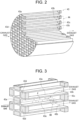
- FIG. 2 illustrates a schematic overall structure of the filter 43
- FIG. 3 is an enlarged view of the AA part illustrated in FIG. 2
- FIG. 4 is an enlarged view of the BB part illustrated in FIG. 3 .
- the filter 43 is disposed such that an inflow passage 43a in which the inflow side of the exhaust gas is opened and the outflow side of the exhaust gas is closed by a lid 43c and an outflow passage 43b in which the inflow side of the exhaust gas is closed by a lid 43d and the outflow side of the exhaust gas is opened are alternately adjacent to each other.
- the exhaust gas flowing into the inflow passage 43a passes through a filter wall 43e between the inflow passage 43a and the outflow passage 43b and flows out from the outflow passage 43b.
- the filter wall 43e has a plurality of micropores 43f through which particulate matters P cannot pass. Therefore, the exhaust gas can pass through the filter wall 43e, but the particulate matters P contained in the exhaust gas cannot pass through the filter wall 43e and is collected.
- FIG. 5 illustrates particulate matters (wall surface deposition particulate matters Pb) that cannot pass through the filter wall 43e and is collected is deposited on the surface of the filter wall 43e.
- the characteristic A reference characteristic
- the deposition state of the particulate matters is the deposition state illustrated in FIG. 5
- the estimation accuracy of the deposition amount estimated from the differential pressure across the filter based on the characteristic A illustrated in FIG. 8 is sufficiently high.
- the deposition state of the particulate matters deposited in the filter 43 and the characteristic of the differential pressure across the filter are not necessarily the deposition state illustrated in FIG. 5 and the characteristic A in FIG. 8 , respectively.
- the deposition state illustrated in FIG. 6 and the characteristic B of FIG. 8 there is a case where the deposition state illustrated in FIG. 7 and the characteristic C of FIG. 8 , or there is a case where both of them are mixed.
- the deposition state illustrated in FIG. 6 indicates a deposition state of the characteristic B in which the differential pressure across the filter deviates to a higher side with respect to the characteristic A (reference characteristic) of FIG. 8 .
- particulate matters (micropore deposition particulate matters Pa) enter at least some of the micropores 43f in the filter wall 43e with respect to the deposition state illustrated in FIG. 5 .
- the particulate matters (micropore deposition particulate matters Pa) first enter the micropores 43f of the filter wall 43e until reaching a saturation state (micropore deposition initial amount), and then the particulate matters (wall surface deposition particulate matters Pb) deposits on the surface of the filter wall 43e.
- the particulate matters (wall surface deposition particulate matters Pb) deposits on the surface of the filter wall 43e, the particulate matters (micropore deposition particulate matters Pa) cannot enter the micropores 43f of the filter wall 43e, and therefore the micropore deposition particulate matters Pa does not increase in amount from the micropore deposition initial amount. Then, the micropore deposition particulate matters Pa is gradually burned and reduced in accordance with the operation state of the internal combustion engine.
- the differential pressure across the filter in this case has the characteristic B illustrated in FIG. 8 .
- the characteristic B first, while the micropore deposition particulate matters Pa deposits in the micropores 43f until reaching a saturation state (micropore deposition initial amount) (while the deposition amount illustrated in FIG. 8 is 0 to Mx), the differential pressure across the filter deviates to a higher side more greatly than the characteristic A. Thereafter, the deviation to the higher side gradually decreases due to incineration by burning of the micropore deposition particulate matters Pa in the micropores 43f, and approaches the characteristic A. That is, regarding the deviation to the higher side of the differential pressure across the filter (the difference between the characteristic A and the characteristic B illustrated in FIG. 8 ), the deviation amount at the initial stage of deposition after completion of filter regeneration is large, and the deviation amount thereafter gradually decreases.
- the deposition state illustrated in FIG. 7 indicates a deposition state of the characteristic C in which the differential pressure across the filter deviates to a lower side with respect to the characteristic A (reference characteristic) of FIG. 8 .
- cracks 43g or the like are generated in a layer of the particulate matters (wall surface deposition particulate matters Pb) deposited on the surface of the filter wall 43e with respect to the deposition state illustrated in FIG. 5 .
- a crack 43g may be generated depending on the operation state. In particular, when the exhaust temperature reaches a high temperature equal to or higher than a predetermined temperature, the cracks 43g are likely to be generated.
- the exhaust gas easily passes in accordance with the amount of the cracks 43g, and the differential pressure across the filter deviates to a lower side. Since the cracks 43g are not recovered, as the cracks 43g increases in accordance with the operation state of the internal combustion engine, the deviation to the lower side of the differential pressure across the filter gradually increases. That is, regarding the deviation (the difference between the characteristic A and the characteristic C illustrated in FIG. 8 ) to the lower side of the differential pressure across the filter, the first deviation amount is small, and then the deviation amount gradually increases.
- the control device 50 of the exhaust purification system 2 described in the present embodiment can estimate the deposition amount (the deposition amount of the particulate matters in the filter 43) with higher accuracy using a corrected differential pressure in which the deviation to the higher side and the deviation to the lower side of the differential pressure across the filter are corrected by the processing described below.
- “deviate to a higher side” means “the differential pressure across the filter deviates to a higher side as in the characteristic B illustrated in FIG. 8 with respect to a reference characteristic (characteristic A in FIG. 8 )".
- “deviation to a lower side” means “the differential pressure across the filter deviates to a lower side as in the characteristic C illustrated in FIG. 8 with respect to the reference characteristic (characteristic A illustrated in FIG. 8 )".
- the corrected differential pressure is obtained using both the increase side correction amount by which the deviation to the lower side of the differential pressure across the filter is corrected and the decrease side correction amount by which the deviation to the higher side of the differential pressure across the filter is corrected.
- the control device 50 (CPU 51) starts the processing shown in FIG. 9 at predetermined time intervals of about several 10 [ms] to several 100 [ms], and advances the processing to step S10.
- PM refers to "particulate matter”.
- step S10 the control device 50 estimates an PM emission amount in accordance with the operation state of the internal combustion engine.
- the control device 50 stores a map in which the rotation speed of the internal combustion engine and the PM emission amount in accordance with the load (or the fuel injection amount) of the internal combustion engine are set, and obtains the PM emission amount based on the map and the operation state of the internal combustion engine.
- the control device 50 adds the PM emission amount to a PM estimation deposition amount (corresponding to the particulate matter deposition amount) to update the PM estimation deposition amount, and advances the processing to step S20.
- the PM estimation deposition amount is an integrated value of the PM emission amount, is used for calculation of an increase side instantaneous correction amount in step T25 of FIG. 10 , which is the processing of step S20 described later, and is reduced in step S75 described later.
- step S20 the control device 50 executes [calculate the increase side correction amount (correction amount for the deviation to the lower side of the differential pressure across the filter)], and advances the processing to step S30. Details of [calculate the increase side correction amount] will be described later.
- step S30 the control device 50 executes [calculate the decrease side correction amount (correction amount for deviation to the higher side of the differential pressure across the filter)] and advances the processing to step S40. Details of the [calculate the decrease side correction amount] will be described later.
- step S40 the control device 50 obtains the corrected differential pressure by adding the increase side correction amount obtained in step S20 to the differential pressure across the filter obtained based on the detection signal from the differential pressure detection device 35, and subtracting the decrease side correction amount obtained in step S30. Then, the control device 50 advances the processing to step S60.
- step S60 the control device 50 determines whether or not a DPF regeneration execution flag is ON. If the DPF regeneration execution flag is ON (Yes), the control device 50 advances the processing to step S75, and if the DPF regeneration execution flag is not ON (No), the control device advances the processing to step S65.
- the DPF regeneration execution flag is a flag set to ON during execution of the "filter regeneration processing (processing of raising temperature of exhaust gas to burn and remove the particulate matters deposited in the filter 43 to regenerate the filter 43)" described later.
- the DPF regeneration execution flag is set to ON in step S70 and set to OFF in step S85.
- the control device 50 determines whether or not the corrected differential pressure exceeds a predetermined threshold. For example, when determining whether or not the deposition amount Ma (corresponding to the predetermined amount) illustrated in FIG. 8 is exceeded, the control device 50 determines whether or not the corrected differential pressure exceeds the differential pressure threshold ⁇ P (corresponding to the predetermined threshold).
- the differential pressure threshold ⁇ P (predetermined threshold) is set to a value corresponding to the deposition amount Ma (predetermined amount). If the corrected differential pressure exceeds the predetermined threshold (Yes), the control device 50 advances the processing to step S70, and if the corrected differential pressure does not exceed the predetermined threshold (No), the processing shown in FIG. 9 ends.
- FIG. 9 shows an example of executing the filter regeneration processing in steps S70 and S75 when the corrected differential pressure exceeds the predetermined threshold in step S65.
- other predetermined conditions are omitted, and when all of the other predetermined conditions are established (satisfied), for example, the rotation speed of the internal combustion engine is within a predetermined range, the fuel injection amount is within a predetermined range, and the accelerator pedal depression amount is within a predetermined range, the filter regeneration processing in steps S70 and S75 is executed.
- the other predetermined conditions are not limited to the above example, and various conditions are set, but are omitted because they are existing conditions.
- the deposition amount of the particulate matters in the filter 43 the deposition amount Ma.
- the deposition amount of the particulate matters in the filter 43 a deposition amount Mb, and the frequency of the filter regeneration processing increases and the fuel consumption increases, which is not very preferable.
- the differential pressure across the filter the differential pressure threshold ⁇ P
- the deposition amount of the particulate matters in the filter 43 a deposition amount Mc
- the deposition amount is larger than the amount assumed, and clogging or the like may be generated in the filter 43, which is not preferable.
- the corrected differential pressure is corrected to have the characteristic Ch in the case of the characteristic C in which the differential pressure across the filter deviates to the lower side with respect to the characteristic A as illustrated in FIG. 12 . Furthermore, as described later, the corrected differential pressure is corrected to have the characteristic Bh in the case of the characteristic B in which the differential pressure across the filter deviates to the higher side with respect to the characteristic A as illustrated in FIG. 15 . Use of this corrected differential pressure enables more accurate estimation of the deposition amount of the particulate matters in the filter 43, enables execution of the filter regeneration processing at an appropriate frequency, and contributes to improvement of fuel efficiency.
- step S70 the control device 50 sets the DPF regeneration execution flag to ON, resets the PM estimation deposition amount, and advances the processing to step S75.
- step S10 the control device 50 obtains the PM estimation deposition amount by the integration type estimation method, but in step S70, resets the PM estimation deposition amount by the differential pressure type estimation method using the corrected differential pressure with higher accuracy due to correction (resetting of the PM estimation deposition amount may be omitted).
- the control device 50 executes the filter regeneration processing (existing processing) and advances processing to step S80.
- the filter regeneration processing is existing processing and thus detail description will be omitted, schematically speaking, fuel is injected from the fuel addition valve 61A illustrated in FIG. 1 and reacted with the first oxidation catalyst 42 to raise the temperature of the exhaust gas, and the PM in the DPF (filter 43) is burned and removed to regenerate the DPF (filter 43). Then, the control device 50 obtains an amount of the PM burned and removed in accordance with exhaust gas temperature, regeneration time, and the like, and updates (reduces) the PM estimation deposition amount.
- the control device 50 determines whether or not the filter regeneration is completed. For example, the control device 50 determines that the filter regeneration is completed when the PM estimation deposition amount updated in step S75 becomes substantially zero (or equal to or less than a predetermined amount). The control device 50 advances the processing to step S85 if determining that the filter regeneration is completed (Yes), and ends the processing shown in FIG. 9 if determining that the filter regeneration is not completed (No).
- the control device 50 sets the DPF regeneration execution flag to OFF, sets a DPF regeneration completion flag to ON, initializes (initializes to zero) the increase side correction amount and the decrease side correction amount, and ends the processing shown in FIG. 9 .
- the DPF regeneration completion flag is used in [calculate the decrease side correction amount] described later.
- step S20 After executing [calculate the increase side correction amount (correction amount for the deviation to the lower side of the differential pressure across the filter)] in step S20 shown in FIG. 9 , the control device 50 advances the processing to step T20 of [calculate increase side correction amount] shown in FIG. 10 .
- step T20 the control device 50 calculates the increase side correction base amount and advances the processing to step T25.
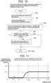
- the storage device (ROM 53) of the control device 50 stores [characteristics of temperature and increase side correction base amount] illustrated in FIG. 11 , for example.
- An increase side correction base amount corresponding to the temperature is set in [characteristics of temperature and increase side correction base amount].
- This temperature is an exhaust gas temperature on the inflow side of the filter 43 or a filter temperature (filter bed temperature) that is a temperature of the filter 43 estimated based on at least one of the exhaust gas temperature on the inflow side and the exhaust gas temperature on the outflow side of the filter 43.
- the control device 50 calculates the increase side correction base amount based on [characteristics of temperature and increase side correction base amount] and the operation state of the internal combustion engine.
- the correction amount per unit PM amount and unit time is set as the increase side correction base amount.
- step T25 the control device 50 calculates the increase side instantaneous correction amount and advances the processing to step T40.
- the control device 50 calculates the increase side instantaneous correction amount by, for example, the following (Expression 1).
- a constant Fc is set to an appropriate value obtained by an experiment, simulation, or the like using an actual vehicle.
- the increase side correction base amount is a correction amount per unit PM amount and unit time
- the increase side instantaneous correction amount multiplied by the PM estimation deposition amount obtained in step S10 of FIG. 9 is a correction amount per unit time.
- Increase side instantaneous correction amount Constant Fc * Increase side correction base amount * PM estimation deposition amount)
- the PM estimation deposition amount (PM deposition amount in the filter 43 recognized by the control device 50) is obtained by the integration type estimation method in step S10 shown in FIG. 9
- the PM estimation deposition amount may be obtained using a known method such as the differential pressure type estimation method or a method using a counter in accordance with elapsed time.
- step T40 the control device 50 adds the increase side instantaneous correction amount to the increase side correction amount to update the increase side correction amount, and advances the processing to step T50.
- the increase side correction amount is initialized (to zero) in step S85 shown in FIG. 9 , and is an integrated value of the increase side instantaneous correction amount after completion of filter reproduction.
- the increase side correction amount in which the increase side instantaneous correction amount is integrated is a correction amount at the present time point after the filter regeneration processing is completed.
- step T50 the control device 50 determines whether or not the increase side correction amount is equal to or less than an upper limit guard amount. If the increase side correction amount is equal to or less than the upper limit guard amount (Yes), the control device 50 ends the processing shown in FIG. 10 and returns the processing to step S20 shown in FIG. 9 , and if the increase side correction amount is larger than the upper limit guard amount (No), the control device advances the processing to step T60.
- a value of the upper limit guard amount is set to an appropriate value obtained by an experiment, simulation, or the like using an actual vehicle.
- control device 50 sets the upper limit guard amount to the increase side correction amount, ends the processing shown in FIG. 10 , and returns the processing below step S20 shown in FIG. 9 .
- the characteristic C is corrected to the characteristic Ch by the increase side correction amount Hc.
- step S30 Upon executing [calculate decrease side correction amount (correction amount for deviation to higher side of differential pressure across the filter)] in step S30 shown in FIG. 9 , the control device 50 advances the processing to step U10 of [calculate decrease side correction amount] shown in FIG. 13 .
- step U10 the control device 50 determines whether or not the DPF regeneration completion flag is set to ON.
- the DPF regeneration completion flag is a flag to be set to ON when the filter regeneration is completed in step S85 shown in FIG. 9 .
- the control device 50 advances the processing to step U15 if the DPF regeneration completion flag is set to ON (Yes), and advances the processing to step U20 if the DPF regeneration completion flag is not set to ON.
- the control device 50 calculates a decrease side initial amount Hbi, initializes (initializes to zero) a decrease side integration amount, sets the DPF regeneration completion flag to OFF, and advances the processing to step U20.
- the decrease side initial amount Hbi is set as a constant corresponding to the internal combustion engine and the filter 43.
- the decrease side integration amount is an amount in which a decrease side instantaneous correction amount is integrated in step U30.
- step U20 the control device 50 calculates the decrease side correction base amount and advances the processing to step U25.
- the storage device (ROM 53) of the control device 50 stores [characteristics of temperature and decrease side correction base amount] illustrated in FIG. 14 , for example.
- a decrease side correction base amount corresponding to the temperature is set in [characteristics of temperature and decrease side correction base amount].
- This temperature is an exhaust gas temperature on the inflow side of the filter 43 or a filter temperature (filter bed temperature) that is a temperature of the filter 43 estimated based on at least one of the exhaust gas temperature on the inflow side and the exhaust gas temperature on the outflow side of the filter 43.
- the control device 50 calculates the decrease side correction base amount based on [characteristics of temperature and decrease side correction base amount] and the operation state of the internal combustion engine.
- the correction amount per unit time is set as the decrease side correction base amount.
- step U25 the control device 50 calculates the decrease side instantaneous correction amount and advances the processing to step U30.
- the control device 50 calculates the decrease side instantaneous correction amount by, for example, the following (Expression 2).
- a constant Fb is set to an appropriate value obtained by an experiment, simulation, or the like using an actual vehicle.
- Decrease side instantaneous correction amount Constant Fb * Decrease side correction base amount
- step U30 the control device adds the decrease side instantaneous correction amount to the decrease side integration amount to update the decrease side integration amount, and advances the processing to step U40.
- the decrease side integration amount is initialized (to zero) in step U15 shown in FIG. 13 , and is an integrated value of the decrease side instantaneous correction amount after completion of filter reproduction.
- the decrease side integration amount in which the decrease side instantaneous correction amount is integrated is an amount at the present time point after the filter regeneration processing is completed.
- step U40 the control device 50 sets, as the decrease side correction amount, a value in which the decrease side integration amount obtained in step U30 is subtracted from the decrease side initial amount obtained in step U15, and advances the processing to step U50.
- step U50 the control device 50 determines whether or not the decrease side correction amount is equal to or greater than a lower limit guard amount. If the decrease side correction amount is equal to or greater than the lower limit guard amount (Yes), the control device 50 ends the processing shown in FIG. 13 and returns the processing below step S30 shown in FIG. 9 , and if the decrease side correction amount is smaller than the lower limit guard amount (No), the control device 50 advances to step U60.
- a value of the lower limit guard amount is set to an appropriate value obtained by an experiment, simulation, or the like using an actual vehicle.
- control device 50 sets the lower limit guard amount to the decrease side correction amount, ends the processing shown in FIG. 13 , and returns the processing below step S30 shown in FIG. 9 .
- the characteristic B is corrected to the characteristic Bh by the decrease side correction amount Hb.
- the corrected differential pressure is obtained in which the characteristic C in which the differential pressure across the filter deviates to the lower side or the characteristic B in which the differential pressure across the filter deviates to the higher side with respect to the characteristic A (reference characteristic) is corrected so as to approach the characteristic A. That is, the corrected differential pressure is obtained using both the increase side correction amount in step S20 and the decrease side correction amount in step S30. Then, by estimating the deposition amount of the particulate matters deposited in the filter 43 using the corrected differential pressure, it is possible to estimate the deposition amount more accurately. Therefore, the filter regeneration processing is avoided from being performed more frequently than necessary, which can contribute to improvement of fuel efficiency. The filter regeneration processing is avoided from being not performed until the deposition amount more than necessary, which can avoid clogging of the filter.
- the processing of the control device 50 (CPU 51) in the second embodiment will be described with reference to the flowchart shown in FIG. 16 .
- the calculation of the decrease side correction amount by which the deviation to the higher side of the differential pressure across the filter is corrected is omitted, and the corrected differential pressure is obtained using only the increase side correction amount by which the deviation to the lower side of the differential pressure across the filter is corrected.
- step S30 (calculation of decrease side correction amount) is omitted with respect to the first embodiment ( FIG. 9 ).
- the flow of processing is changed from step S40 to step S42 in which the decrease side correction amount is omitted, and the flow of processing is changed from step S85 to step S87 in which the processing of setting the DPF regeneration completion flag to ON and the processing of initializing the decrease side correction amount are omitted.
- Other steps are the same as those in the first embodiment.
- step S20 only the increase side correction amount in step S20 is obtained to obtain the corrected differential pressure.
- the increase side correction amount is necessary, but since the characteristic B deviated to the higher side has the deviation amount that gradually decreases, the decrease side correction amount is omitted.
- the filter regeneration processing is avoided from being not performed until the deposition amount more than necessary, which can avoid clogging of the filter.
- the exhaust purification system 2 for the internal combustion engine of the present invention is not limited to the configurations, structures, processing procedures, and the like described in the present embodiments, and various changes, additions, and deletions can be made without changing the gist of the present invention.
- the exhaust purification system 2 for the internal combustion engine of the present invention is not limited to a vehicle equipped with a diesel engine, and the present invention can be applied to various devices equipped with a diesel engine.
Landscapes
- Engineering & Computer Science (AREA)
- Chemical & Material Sciences (AREA)
- Combustion & Propulsion (AREA)
- Mechanical Engineering (AREA)
- General Engineering & Computer Science (AREA)
- Processes For Solid Components From Exhaust (AREA)
Abstract
An exhaust purification system (2) for an internal combustion engine (10) includes a filter (43) collecting a particulate matter in an exhaust gas, a differential pressure detection device (35) detecting a differential pressure across the filter, and a control device (50). The control device (50) executes filter regeneration processing of burning and removing the particulate matter deposited in the filter (43) when determining that the particulate matter exceeding a predetermined amount deposits in the filter (43) and a predetermined condition is satisfied, obtains, based on an operation state, an increase side correction amount by which the differential pressure across the filter is corrected to an increase side, obtains a corrected differential pressure in which the differential pressure across the filter is corrected using the increase side correction amount, and determines that the particulate matter exceeding the predetermined amount deposits in the filter (43) when the corrected differential pressure exceeds a predetermined threshold set in accordance with the predetermined amount.
Description
- The present invention relates to an exhaust purification system for an internal combustion engine.
- Conventionally, a vehicle equipped with a diesel engine as an internal combustion engine collects micro particulate matters (PM) in an exhaust gas by a filter (diesel particulate filter (DPF)) provided in an exhaust passage so as not to release the particulate matters to the atmosphere. The filter has a wall provided with a large number of micropores that do not allow the particulate matters to pass therethrough, and the exhaust gas is passed through the micropores of the wall so that the particulate matters are collected.
- The collected particulate matters deposits in the filter, and the filter is clogged unless the deposited particulate matters is periodically removed. Therefore, filter regeneration processing of burning and removing the particulate matters deposited in the filter is periodically performed. In the filter regeneration processing, the temperature of the exhaust gas of about 300 to 400 [°C] is forcibly raised to about 600 [°C] or more in a normal operation state, and the particulate matters deposited in the filter is burned and removed. When the temperature of the exhaust gas is forcibly raised, fuel is added to the exhaust gas, and the fuel is reacted with an oxidation catalyst disposed on the upstream side of the filter to raise the temperature of the exhaust gas, and therefore the fuel is consumed.
- Execution of the filter regeneration processing is not preferable when the frequency is more than necessary because the fuel efficiency deteriorates, and is not preferable when the frequency is less than necessary because the filter may be clogged. Therefore, it is necessary to perform the filter regeneration processing at an appropriate frequency, and thus it is necessary to accurately detect the deposition amount of the particulate matters in the filter.
- The deposition amount of the particulate matters in the filter cannot be directly detected, and as methods of estimating the deposition amount, the following methods (1) and (2) are generally used. (1) An integration type estimation method of estimating the deposition amount of particulate matters by measuring and mapping a generation amount of the particulate matters in accordance with the operation state of the internal combustion engine using an actual vehicle, and obtaining and integrating the generation amount in accordance with the operation state at a predetermined time interval. (2) A differential pressure type estimation method of measuring a differential pressure across the filter (pressure difference between an inflow side and an outflow side of the filter) and estimating the deposition amount of the particulate matters based on this differential pressure across the filter.
- The integration type estimation method of (1) described above is not preferable because an error due to variation, deterioration, and the like of the internal combustion engine is relatively large, and the estimation accuracy is lower than that of the differential pressure type estimation method of (2). In the differential pressure type estimation method of (2) described above, there is a case where the differential pressure across the filter deviates to a higher side or a lower side with respect to a reference differential pressure in relation to the deposition amount of the particulate matters. Therefore, it is desired to appropriately correct the detected differential pressure across the filter.
- A deviation (error) to a higher side with respect to a reference characteristic of the differential pressure across the filter is generated due to a phenomenon described below. The particulate matters depositing in the filter includes particulate matters (micropore deposition particulate matter) that has entered micropores in a wall of the filter and particulate matters (wall surface deposition particulate matter) that deposits on the surface of the wall of the filter. The exhaust gas hardly passes through the filter depending on the amount of the micropore deposition particulate matters (see
FIG. 6 ), and the particulate matters deviates to a side where the differential pressure across the filter is high. In a filter in which particulate matters do not deposit immediately after completion of the filter regeneration processing, the particulate matters (micropore deposition particulate matter) first enter the micropores in the wall of the filter until reaching a saturation state (micropore deposition initial amount), and then the particulate matters (wall surface deposition particulate matter) deposits on the wall surface of the filter. As the particulate matters deposit on the wall surface of the filter, the particulate matters cannot enter the micropores in the wall of the filter, and therefore the micropore deposition particulate matters does not increase in amount from the micropore deposition initial amount. Then, the micropore deposition particulate matters are gradually burned and reduced depending on the operation state of the internal combustion engine, and the deviation to the higher side of the differential pressure across the filter gradually decreases. That is, the deviation amount to the higher side of the differential pressure across the filter is large at an initial stage, and then the deviation amount gradually decreases (see a characteristic B deviated to a higher side with respect to a reference characteristic A illustrated inFIG. 8 ). - A deviation (error) to a lower side with respect to a reference characteristic of the differential pressure across the filter is generated due to a phenomenon described below. When a crack or the like is generated in a layer of the particulate matters (wall surface deposition particulate matter) deposited on the wall surface of the filter based on the operation state of the internal combustion engine, the exhaust gas easily passes in accordance with the amount of the crack or the like (see
FIG. 7 ), and the differential pressure across the filter deviates to a lower side. As the filter regeneration processing is performed and the particulate matters (wall surface deposition particulate matter) deposits on the surface of the wall of the filter, a cleavage, a crack, and the like may be generated depending on the operation state of the internal combustion engine. Since the cleavage, the crack, and the like are not recovered, as the cleavage, the crack, and the like increase depending on the operation state of the internal combustion engine, the deviation to the lower side of the differential pressure across the filter gradually increases. That is, regarding the deviation to the lower side of the differential pressure across the filter, the first deviation amount is small, and then the deviation amount gradually increases (see a characteristic C deviated to a lower side with respect to the reference characteristic A illustrated inFIG. 8 ). - For example,
Japanese Patent Application Publication No. 2007-170193 Japanese Patent Application Publication No. 2007-170193 - For example, in
Japanese Patent Application Publication No. 2010-190120 - The deposition of the particulate matters (micropore deposition particulate matter) in the micropores of the wall of the filter, the burning of the micropore deposition particulate matters, and generation of a cleavage, a crack, and the like of the wall surface deposition particulate matters vary depending on the operation state of the internal combustion engine, and only one or both may occur. That is, depending on the operation state of the internal combustion engine, the differential pressure across the filter may deviate to a higher side or greatly deviate to a lower side with respect to the reference characteristic. Therefore, when correcting the differential pressure across the filter, it is preferable to perform both the correction for the deviation to the higher side and the correction for the deviation to the lower side, but it is preferable to perform at least the correction for the deviation to the lower side in which the deviation amount gradually increases.
- The invention described in
Japanese Patent Application Publication No. 2007-170193 - The invention described in
Japanese Patent Application Publication No. 2010-190120 Japanese Patent Application Publication No. 2010-190120 - The present invention, which has been made in light of the above-mentioned problem, is directed to providing an exhaust purification system for an internal combustion engine wherein the exhaust purification system can further improve the estimation accuracy by appropriately correcting the differential pressure across the filter when estimating the deposition amount of the particulate matters in the filter based on the differential pressure across the filter.
- In accordance with one aspect of the present invention, there is provided an exhaust purification system for an internal combustion engine, the exhaust purification system including: a filter that is disposed in an exhaust passage of the internal combustion engine and collects a particulate matter contained in an exhaust gas from the internal combustion engine; a differential pressure detection device that detects a differential pressure across the filter, the differential pressure being a pressure difference of the exhaust gas between an inflow side and an outflow side of the filter; and a control device that detects an operation state of the internal combustion engine and controls the internal combustion engine based on the operation state that is detected. In the exhaust purification system of an internal combustion engine, the control device executes filter regeneration processing of burning and removing the particulate matter deposited in the filter when determining that the particulate matter exceeding a predetermined amount deposits in the filter and a predetermined condition is satisfied, obtains, based on the operation state, an increase side correction amount by which the differential pressure across the filter detected using the differential pressure detection device is corrected to an increase side, obtains a corrected differential pressure in which the differential pressure across the filter is corrected using the increase side correction amount, and determines that the particulate matter exceeding the predetermined amount deposits in the filter when the corrected differential pressure exceeds a predetermined threshold set in accordance with the predetermined amount.
- In accordance with another aspect of the present invention, there is provided an exhaust purification system for an internal combustion engine, the exhaust purification system including: a filter that is disposed in an exhaust passage of the internal combustion engine and collects a particulate matter contained in an exhaust gas from the internal combustion engine; a differential pressure detection device that detects a differential pressure across the filter, the differential pressure being a pressure difference of the exhaust gas between an inflow side and an outflow side of the filter; and a control device that detects an operation state of the internal combustion engine and controls the internal combustion engine based on the operation state that is detected. In the exhaust purification system of an internal combustion engine, the control device executes filter regeneration processing of burning and removing the particulate matter deposited in the filter when determining that the particulate matter exceeding a predetermined amount deposits in the filter and a predetermined condition is satisfied, obtains, based on the operation state, both an increase side correction amount by which the differential pressure across the filter detected using the differential pressure detection device is corrected to an increase side and a decrease side correction amount by which the differential pressure across the filter is corrected to a decrease side, obtains a corrected differential pressure in which the differential pressure across the filter is corrected using both the increase side correction amount and the decrease side correction amount, and determines that the particulate matter exceeding the predetermined amount deposits in the filter when the corrected differential pressure exceeds a predetermined threshold set in accordance with the predetermined amount.
- The invention, together with objects and advantages thereof, may best be understood by reference to the following description of the embodiments together with the accompanying drawings in which:
-
FIG. 1 is a view illustrating an example of an overall configuration of an internal combustion engine system; -
FIG. 2 is a view illustrating an example of a structure of a filter (DPF); -
FIG. 3 is an enlarged view of an AA part illustrated inFIG. 2 ; -
FIG. 4 is an enlarged view of a BB part illustrated inFIG. 3 ; -
FIG. 5 is a view illustrating a normal state where particulate matters deposit on a surface of a wall of the filter (DPF); -
FIG. 6 is a view illustrating a state where particulate matters deposit on the surface of the wall of the filter (DPF) and micropores of the wall; -
FIG. 7 is a view illustrating a state where a crack or the like occurs in the particulate matters depositing on the surface of the wall of the filter (DPF); -
FIG. 8 is a view showing a relationship between a deposition amount of the particulate matters in the filter and a differential pressure across the filter; -
FIG. 9 is a flowchart showing an example of a processing procedure of [overall processing] of a control device in a first embodiment; -
FIG. 10 is a flowchart showing an example of a processing procedure of [calculate the increase side correction amount]; -
FIG. 11 is a view illustrating an example of [characteristics of temperature and increase side correction base amount]; -
FIG. 12 is an image view for correcting a characteristic C deviated to a lower side with respect to the characteristic A (reference characteristic) of the differential pressure across the filter to a characteristic Ch by an increase side correction amount Hc; -
FIG. 13 is a flowchart showing an example of a processing procedure of [calculate the decrease side correction amount]; -
FIG. 14 is a view illustrating an example of [characteristics of temperature and decrease side correction base amount]; -
FIG. 15 is an image view for correcting a characteristic B deviated to a higher side with respect to the characteristic A (reference characteristic) of the differential pressure across the filter to a characteristic Bh by a decrease side correction amount Hb; and -
FIG. 16 is a flowchart showing an example of a processing procedure of [overall processing] of a control device in a second embodiment. - Hereinafter, an internal
combustion engine system 1 including anexhaust purification system 2 of the present invention will be described with reference to the drawings. First, an example of the overall configuration of the internalcombustion engine system 1 will be described with reference toFIG. 1 . Aninternal combustion engine 10 of the internalcombustion engine system 1 in the example ofFIG. 1 is what is called a diesel engine. Theexhaust purification system 2 includes acontrol device 50, a filter 43 (particulate matter collection filter), and a differentialpressure detection device 35. Hereinafter, the configuration and the like of the internalcombustion engine system 1 will be described in order from an intake side to an exhaust side. - An
intake pipe 11A is provided with an air flowrate detection device 31. The air flow rate detection device 31 (e.g., an intake flow rate sensor) outputs, to thecontrol device 50, a detection signal corresponding to a flow rate [g/sec] of air sucked by theinternal combustion engine 10. The air flowrate detection device 31 is provided with an intaketemperature detection device 32A and an atmosphericpressure detection device 33A. The intaketemperature detection device 32A (e.g., an intake temperature sensor) outputs, to thecontrol device 50, a detection signal corresponding to the temperature of intake air (in this case, outside air). The atmosphericpressure detection device 33A (e.g., a pressure sensor) outputs, to thecontrol device 50, a detection signal corresponding to the atmospheric pressure. Theintake pipe 11A is connected to acompressor 82 of asupercharger 80. - The
intake pipe 11A is connected to an inflow side of thecompressor 82, and anintake pipe 11C is connected to a discharge side of thecompressor 82. Thecompressor 82 is rotationally driven by aturbine 81, and pumps, to theintake pipe 11C, the intake air flowing in from theintake pipe 11A. Theintake pipe 11A on an upstream side of thecompressor 82 is provided with apressure detection device 33B. Thepressure detection device 33B (e.g., a pressure sensor) outputs, to thecontrol device 50, a detection signal corresponding to the pressure of the air before being compressed by thecompressor 82. - A downstream side of the
intake pipe 11C is connected to anintake manifold 11D. Theintake pipe 11C is provided with a pressure detection device 33C, anintercooler 84, athrottle device 64, and an intaketemperature detection device 32B. The pressure detection device 33C (e.g., a pressure sensor) outputs, to thecontrol device 50, a detection signal corresponding to the pressure of the intake air pumped by thecompressor 82. Theintercooler 84 lowers the temperature of the intake air pumped from thecompressor 82 to increase the oxygen density. Thethrottle device 64 adjusts the opening of a throttle valve to a target throttle opening based on a control signal from thecontrol device 50. The intaketemperature detection device 32B (e.g., an intake temperature sensor) outputs, to thecontrol device 50, a detection signal corresponding to the temperature of the intake air lowered by theintercooler 84. - A downstream side of the
intake manifold 11D is connected to an intake port guiding the intake air to each cylinder of theinternal combustion engine 10. The intake air guided to theintake manifold 11D is sucked into each cylinder of theinternal combustion engine 10 and used for burning together with a fuel injected from aninjector 21. Theintake manifold 11D is provided with apressure detection device 33D. Thepressure detection device 33D (e.g., a pressure sensor) outputs, to thecontrol device 50, a detection signal corresponding to the pressure of the intake air in theintake manifold 11D. - The
internal combustion engine 10 is provided with arotation detection device 34A and acylinder detection device 34B. Therotation detection device 34A (e.g., a rotation sensor of a crankshaft) outputs, to thecontrol device 50, a detection signal (crank angle signal) corresponding to a rotation angle of a crankshaft of theinternal combustion engine 10. Thecylinder detection device 34B (e.g., a rotation sensor of a camshaft) outputs, to thecontrol device 50, a detection signal (cylinder determination signal) when a piston of the first cylinder reaches a compression top dead center, for example. Theinternal combustion engine 10 is provided with aload device 63 that can adjust a load of theinternal combustion engine 10. Theload device 63 is, for example, an alternator, and changes the load of theinternal combustion engine 10 based on a load control signal (power generation control signal) from thecontrol device 50. Theinternal combustion engine 10 is provided with a coolanttemperature detection device 32C. The coolanttemperature detection device 32C (e.g., a water temperature sensor) outputs, to thecontrol device 50, a detection signal corresponding to the temperature of a coolant (cooling water) that cools the internal combustion engine. - An accelerator depression amount detection device 38 (e.g., an accelerator depression amount sensor) outputs, to the
control device 50, a detection signal corresponding to a depression amount of an accelerator pedal operated by an operator. Anignition switch 39 is an input device for an instruction to start or stop the internal combustion engine from the operator. - The
control device 50 calculates a required load based on the rotation speed of the internal combustion engine based on the detection signal from therotation detection device 34A and the depression amount of the accelerator pedal based on the detection signal from the accelerator depressionamount detection device 38, and calculates a fuel amount in accordance with the required load. Then, based on the detection signals from therotation detection device 34A and thecylinder detection device 34B, thecontrol device 50 controls theinjector 21 at a predetermined timing, and injects a fuel amount in accordance with the required load into each cylinder of a #1 cylinder to a #4 cylinder of theinternal combustion engine 10. - An
exhaust manifold 12A is connected to an exhaust port of theinternal combustion engine 10. The exhaust gas from theinternal combustion engine 10 is guided to theexhaust manifold 12A, anexhaust pipe 12B, and theturbine 81 of thesupercharger 80, rotationally drives theturbine 81, and is discharged to anexhaust pipe 12C. The exhaust gas from theinternal combustion engine 10 contains carbon monoxide (CO), hydrocarbon (HC), particulate matters (PM), nitrogen oxide (NOx), and the like. - An inflow side of an
EGR pipe 13 for returning part of the exhaust gas to the intake air is connected to theexhaust manifold 12A or theexhaust pipe 12B. An outflow side of theEGR pipe 13 is connected to theintake pipe 11C or theintake manifold 11D. TheEGR pipe 13 is provided with anEGR valve 13A controlled by thecontrol device 50 to adjust the opening of the EGR pipe. - The
exhaust pipe 12B is connected to an outflow side of theexhaust manifold 12A. An inflow side of theturbine 81 of thesupercharger 80 is connected to a downstream side of theexhaust pipe 12B. Theexhaust pipe 12C is connected to an outflow side of theturbine 81, and anexhaust purification device 40 is connected to a downstream side of theexhaust pipe 12C. - The
exhaust purification device 40 includes an upstream sideexhaust purification device 41 and a downstream sideexhaust purification device 45 disposed downstream of the upstream sideexhaust purification device 41. The upstream sideexhaust purification device 41 includes a first oxidation catalyst 42 (diesel oxidation catalyst: DOC) and a filter 43 (diesel particulate filter: DPF) from the upstream side. The downstream sideexhaust purification device 45 includes a urea SCR 46 (selective catalytic reduction: SCR, SCR catalyst) and a second oxidation catalyst 47 (diesel oxidation catalyst: DOC) from the upstream side. - The
first oxidation catalyst 42 causes an oxidation reaction of and purifies carbon monoxide (CO), hydrocarbon (HC), and the like contained in the exhaust gas. Thefilter 43 collects particulate matters (PM) contained in the exhaust gas and allows only the exhaust gas to flow out to the downstream side. Thefilter 43 also has a function of causing an oxidation reaction of and purifying carbon monoxide and hydrocarbon. - The
exhaust pipe 12C on the upstream side of thefirst oxidation catalyst 42 is provided with afuel addition valve 61A, an exhausttemperature detection device 36A (e.g., an exhaust temperature sensor), and the like. Thefuel addition valve 61A can add (inject) fuel, and injects, into theexhaust pipe 12C, fuel (reaction liquid) for raising the temperature of the exhaust gas by causing an oxidation reaction in thefirst oxidation catalyst 42 when executing filter regeneration processing of regenerating thefilter 43 in which the collected particulate matters is deposited (when burning and removing the particulate matters). Adispersion device 61B that collides and disperses the fuel injected from thefuel addition valve 61A is disposed in theexhaust pipe 12C. Thefuel addition valve 61A is supplied with fuel from afuel tank 90. - The downstream side of the
first oxidation catalyst 42 as well as the upstream side of thefilter 43 is provided with an exhausttemperature detection device 36B (e.g., an exhaust temperature sensor). The downstream side of thefilter 43 is provided with an exhausttemperature detection device 36C (e.g., an exhaust temperature sensor). The exhausttemperature detection devices control device 50, detection signals corresponding to the temperature of the exhaust gas. - The differential pressure detection device 35 (e.g., a differential pressure sensor) that detects a differential pressure (pressure difference) between the exhaust pressure on the downstream side of the
first oxidation catalyst 42 as well as the upstream side of thefilter 43 and the exhaust pressure on the downstream side of thefilter 43. The differentialpressure detection device 35 outputs, to thecontrol device 50, a detection signal corresponding to a differential pressure across the filter, which is a pressure difference between the pressure on the upstream side and the pressure on the downstream side of thefilter 43. - The downstream side
exhaust purification device 45 is provided with a ureawater addition valve 62A, adispersion device 62B, theurea SCR 46, thesecond oxidation catalyst 47, and the like from the upstream side. Theurea SCR 46 is coupled to the downstream side of thefilter 43 via anexhaust pipe 12D. The ureawater addition valve 62A can add (inject) urea water, is disposed in theexhaust pipe 12D on the downstream side of thefilter 43 as well as the upstream side of theurea SCR 46, and injects urea water (reaction liquid) into the exhaust gas at a predetermined timing. The injected urea water collides with and scatters to be atomized by thedispersion device 62B, diffuses in theexhaust pipe 12D, and reaches theurea SCR 46. The ureawater addition valve 62A is supplied with urea water from a urea water tank not illustrated. Using ammonia gas generated from the added urea water, theurea SCR 46 reduces and purifies nitrogen oxides (NOx) contained in the exhaust gas. - The
exhaust pipe 12D on the upstream side of theurea SCR 46 is provided with anNOx detection device 37A (e.g., an NOx sensor). Anexhaust pipe 12E on the downstream side of theurea SCR 46 is provided with anNOx detection device 37B (e.g., an NOx sensor) and an exhausttemperature detection device 36D (e.g., an exhaust temperature sensor). TheNOx detection devices control device 50, detection signals corresponding to the concentration of NOx in the exhaust gas, and the exhausttemperature detection device 36D outputs, to thecontrol device 50, detection signals corresponding to the temperature of the exhaust gas. Thecontrol device 50 calculates an NOx purification rate of theurea SCR 46 based on the detection signals of theNOx detection devices temperature detection device 36D, and controls the ureawater addition valve 62A based on the calculated NOx purification rate. Theexhaust pipes - The
second oxidation catalyst 47 is coupled to the downstream side of theurea SCR 46 via theexhaust pipe 12E. Thesecond oxidation catalyst 47 oxidizes and purifies the ammonia gas remaining in the exhaust gas. Thesecond oxidation catalyst 47 also has a function of causing an oxidation reaction of and purifying carbon monoxide and hydrocarbon. - The
control device 50 is a known device including aCPU 51, aRAM 52, a ROM 53 (storage device), atimer 54, and a nonvolatile storage device 55 (e.g., an EEPROM). TheCPU 51 executes various arithmetic processing based on various programs and maps stored in the ROM 53 (e.g., a Flash-ROM). TheRAM 52 temporarily stores an arithmetic result in the CPU, data input from each detection device, and the like, and thenonvolatile storage device 55 stores data to be saved, for example, when theinternal combustion engine 10 is stopped. - Then, the
control device 50 can detect the operation state of theinternal combustion engine 10 based on the detection signal that is input. In response to a request from the operator based on the operation state of theinternal combustion engine 10 that is detected and a detection signal from the accelerator depressionamount detection device 38, thecontrol device 50 outputs a control signal for controlling various actuators such as theinjector 21 that injects fuel into the cylinder, thefuel addition valve 61A, the ureawater addition valve 62A, and theEGR valve 13A. - The
control device 50 can detect a differential pressure across the filter, which is a pressure difference between the upstream side and the downstream side of thefilter 43, based on the detection signal from the differentialpressure detection device 35, and can estimate the deposition amount of the particulate matters collected in thefilter 43 based on the detected differential pressure across the filter. Then, when the estimation deposition amount exceeds a threshold, thecontrol device 50 executes the filter regeneration processing to inject fuel (reaction liquid) from thefuel addition valve 61A to raise the exhaust temperature, and burns and removes the particulate matters deposited in thefilter 43 to regenerate thefilter 43. - Since the filter regeneration processing described above consumes fuel, fuel efficiency may deteriorate if the filter regeneration processing is executed at a frequency more than necessary, and the
filter 43 may be clogged if the frequency is low. In order to execute the filter regeneration processing at an appropriate frequency, it is necessary to accurately estimate the deposition amount of the particulate matters deposited in thefilter 43. However, as described below, the differential pressure across the filter based on the detection signal from the differentialpressure detection device 35 sometimes deviates to a higher side or a lower side with respect to a reference characteristic. - First, the structure of the
filter 43 will be described with reference toFIGS. 2 to 4 .FIG. 2 illustrates a schematic overall structure of thefilter 43,FIG. 3 is an enlarged view of the AA part illustrated inFIG. 2 , andFIG. 4 is an enlarged view of the BB part illustrated inFIG. 3 . - As illustrated in
FIG. 2 , thefilter 43 is disposed such that aninflow passage 43a in which the inflow side of the exhaust gas is opened and the outflow side of the exhaust gas is closed by alid 43c and anoutflow passage 43b in which the inflow side of the exhaust gas is closed by alid 43d and the outflow side of the exhaust gas is opened are alternately adjacent to each other. - As illustrated in
FIG. 3 , the exhaust gas flowing into theinflow passage 43a passes through afilter wall 43e between theinflow passage 43a and theoutflow passage 43b and flows out from theoutflow passage 43b. - As illustrated in
FIG. 4 , thefilter wall 43e has a plurality ofmicropores 43f through which particulate matters P cannot pass. Therefore, the exhaust gas can pass through thefilter wall 43e, but the particulate matters P contained in the exhaust gas cannot pass through thefilter wall 43e and is collected. -
FIG. 5 illustrates particulate matters (wall surface deposition particulate matters Pb) that cannot pass through thefilter wall 43e and is collected is deposited on the surface of thefilter wall 43e. In a deposition state illustrated inFIG. 5 , the relationship between the deposition amount of the particulate matters in thefilter 43 and the differential pressure across the filter is the characteristic A (reference characteristic) illustrated inFIG. 8 . The storage device of thecontrol device 50 stores the deposition amount and a differential pressure characteristic of the characteristic A illustrated inFIG. 8 . Then, based on the characteristic A illustrated inFIG. 8 , thecontrol device 50 determines (estimates) that the deposition amount = a deposition amount Ma when the differential pressure across the filter = a differential pressure threshold ΔP. When the deposition state of the particulate matters is the deposition state illustrated inFIG. 5 , the estimation accuracy of the deposition amount estimated from the differential pressure across the filter based on the characteristic A illustrated inFIG. 8 is sufficiently high. However, the deposition state of the particulate matters deposited in thefilter 43 and the characteristic of the differential pressure across the filter are not necessarily the deposition state illustrated inFIG. 5 and the characteristic A inFIG. 8 , respectively. Depending on the operation state of the internal combustion engine, there is a case where the deposition state illustrated inFIG. 6 and the characteristic B ofFIG. 8 , there is a case where the deposition state illustrated inFIG. 7 and the characteristic C ofFIG. 8 , or there is a case where both of them are mixed. - The deposition state illustrated in
FIG. 6 indicates a deposition state of the characteristic B in which the differential pressure across the filter deviates to a higher side with respect to the characteristic A (reference characteristic) ofFIG. 8 . In the deposition state illustrated inFIG. 6 , particulate matters (micropore deposition particulate matters Pa) enter at least some of themicropores 43f in thefilter wall 43e with respect to the deposition state illustrated inFIG. 5 . In thefilter 43 in which particulate matters do not deposit by the filter regeneration processing, the particulate matters (micropore deposition particulate matters Pa) first enter themicropores 43f of thefilter wall 43e until reaching a saturation state (micropore deposition initial amount), and then the particulate matters (wall surface deposition particulate matters Pb) deposits on the surface of thefilter wall 43e. As the particulate matters (wall surface deposition particulate matters Pb) deposits on the surface of thefilter wall 43e, the particulate matters (micropore deposition particulate matters Pa) cannot enter themicropores 43f of thefilter wall 43e, and therefore the micropore deposition particulate matters Pa does not increase in amount from the micropore deposition initial amount. Then, the micropore deposition particulate matters Pa is gradually burned and reduced in accordance with the operation state of the internal combustion engine. - Since the micropore deposition particulate matters Pa blocks the
micropores 43f through which the exhaust gas passes, the differential pressure across the filter deviates to a higher side. Therefore, the differential pressure across the filter in this case has the characteristic B illustrated inFIG. 8 . In the characteristic B, first, while the micropore deposition particulate matters Pa deposits in themicropores 43f until reaching a saturation state (micropore deposition initial amount) (while the deposition amount illustrated inFIG. 8 is 0 to Mx), the differential pressure across the filter deviates to a higher side more greatly than the characteristic A. Thereafter, the deviation to the higher side gradually decreases due to incineration by burning of the micropore deposition particulate matters Pa in themicropores 43f, and approaches the characteristic A. That is, regarding the deviation to the higher side of the differential pressure across the filter (the difference between the characteristic A and the characteristic B illustrated inFIG. 8 ), the deviation amount at the initial stage of deposition after completion of filter regeneration is large, and the deviation amount thereafter gradually decreases. - The deposition state illustrated in
FIG. 7 indicates a deposition state of the characteristic C in which the differential pressure across the filter deviates to a lower side with respect to the characteristic A (reference characteristic) ofFIG. 8 . In the deposition state illustrated inFIG. 7 , cracks 43g or the like are generated in a layer of the particulate matters (wall surface deposition particulate matters Pb) deposited on the surface of thefilter wall 43e with respect to the deposition state illustrated inFIG. 5 . As illustrated inFIG. 5 , as the particulate matters (wall surface deposition particulate matters Pb) deposits on the surface of thefilter wall 43e, acrack 43g may be generated depending on the operation state. In particular, when the exhaust temperature reaches a high temperature equal to or higher than a predetermined temperature, thecracks 43g are likely to be generated. - When the
cracks 43g are generated in accordance with the operation state of the internal combustion engine, the exhaust gas easily passes in accordance with the amount of thecracks 43g, and the differential pressure across the filter deviates to a lower side. Since thecracks 43g are not recovered, as thecracks 43g increases in accordance with the operation state of the internal combustion engine, the deviation to the lower side of the differential pressure across the filter gradually increases. That is, regarding the deviation (the difference between the characteristic A and the characteristic C illustrated inFIG. 8 ) to the lower side of the differential pressure across the filter, the first deviation amount is small, and then the deviation amount gradually increases. - The
control device 50 of theexhaust purification system 2 described in the present embodiment can estimate the deposition amount (the deposition amount of the particulate matters in the filter 43) with higher accuracy using a corrected differential pressure in which the deviation to the higher side and the deviation to the lower side of the differential pressure across the filter are corrected by the processing described below. In the description of the present embodiment, "deviate to a higher side" means "the differential pressure across the filter deviates to a higher side as in the characteristic B illustrated inFIG. 8 with respect to a reference characteristic (characteristic A inFIG. 8 )". In addition, "deviation to a lower side" means "the differential pressure across the filter deviates to a lower side as in the characteristic C illustrated inFIG. 8 with respect to the reference characteristic (characteristic A illustrated inFIG. 8 )". - Next, the processing of the control device 50 (CPU 51) in the first embodiment will be described with reference to flowcharts and the like shown in
FIGS. 9 to 15 . In the first embodiment, the corrected differential pressure is obtained using both the increase side correction amount by which the deviation to the lower side of the differential pressure across the filter is corrected and the decrease side correction amount by which the deviation to the higher side of the differential pressure across the filter is corrected. - The control device 50 (CPU 51) starts the processing shown in
FIG. 9 at predetermined time intervals of about several 10 [ms] to several 100 [ms], and advances the processing to step S10. In the following description, "PM" refers to "particulate matter". - In step S10, the
control device 50 estimates an PM emission amount in accordance with the operation state of the internal combustion engine. For example, thecontrol device 50 stores a map in which the rotation speed of the internal combustion engine and the PM emission amount in accordance with the load (or the fuel injection amount) of the internal combustion engine are set, and obtains the PM emission amount based on the map and the operation state of the internal combustion engine. Then, thecontrol device 50 adds the PM emission amount to a PM estimation deposition amount (corresponding to the particulate matter deposition amount) to update the PM estimation deposition amount, and advances the processing to step S20. The PM estimation deposition amount is an integrated value of the PM emission amount, is used for calculation of an increase side instantaneous correction amount in step T25 ofFIG. 10 , which is the processing of step S20 described later, and is reduced in step S75 described later. - In step S20, the
control device 50 executes [calculate the increase side correction amount (correction amount for the deviation to the lower side of the differential pressure across the filter)], and advances the processing to step S30. Details of [calculate the increase side correction amount] will be described later. - In step S30, the
control device 50 executes [calculate the decrease side correction amount (correction amount for deviation to the higher side of the differential pressure across the filter)] and advances the processing to step S40. Details of the [calculate the decrease side correction amount] will be described later. - In step S40, the
control device 50 obtains the corrected differential pressure by adding the increase side correction amount obtained in step S20 to the differential pressure across the filter obtained based on the detection signal from the differentialpressure detection device 35, and subtracting the decrease side correction amount obtained in step S30. Then, thecontrol device 50 advances the processing to step S60. - In step S60, the
control device 50 determines whether or not a DPF regeneration execution flag is ON. If the DPF regeneration execution flag is ON (Yes), thecontrol device 50 advances the processing to step S75, and if the DPF regeneration execution flag is not ON (No), the control device advances the processing to step S65. The DPF regeneration execution flag is a flag set to ON during execution of the "filter regeneration processing (processing of raising temperature of exhaust gas to burn and remove the particulate matters deposited in thefilter 43 to regenerate the filter 43)" described later. The DPF regeneration execution flag is set to ON in step S70 and set to OFF in step S85. - If advancing the processing to step S65, the
control device 50 determines whether or not the corrected differential pressure exceeds a predetermined threshold. For example, when determining whether or not the deposition amount Ma (corresponding to the predetermined amount) illustrated inFIG. 8 is exceeded, thecontrol device 50 determines whether or not the corrected differential pressure exceeds the differential pressure threshold ΔP (corresponding to the predetermined threshold). The differential pressure threshold ΔP (predetermined threshold) is set to a value corresponding to the deposition amount Ma (predetermined amount). If the corrected differential pressure exceeds the predetermined threshold (Yes), thecontrol device 50 advances the processing to step S70, and if the corrected differential pressure does not exceed the predetermined threshold (No), the processing shown inFIG. 9 ends. - The example of
FIG. 9 shows an example of executing the filter regeneration processing in steps S70 and S75 when the corrected differential pressure exceeds the predetermined threshold in step S65. However, other predetermined conditions are omitted, and when all of the other predetermined conditions are established (satisfied), for example, the rotation speed of the internal combustion engine is within a predetermined range, the fuel injection amount is within a predetermined range, and the accelerator pedal depression amount is within a predetermined range, the filter regeneration processing in steps S70 and S75 is executed. The other predetermined conditions are not limited to the above example, and various conditions are set, but are omitted because they are existing conditions. - As illustrated in
FIG. 8 , when the characteristic of the differential pressure across the filter is the characteristic A, if the differential pressure across the filter = the differential pressure threshold ΔP, the deposition amount of the particulate matters in thefilter 43 = the deposition amount Ma. However, in the case of the characteristic B in which the differential pressure across the filter deviates to the higher side, if the differential pressure across the filter = the differential pressure threshold ΔP, the deposition amount of the particulate matters in thefilter 43 = a deposition amount Mb, and the frequency of the filter regeneration processing increases and the fuel consumption increases, which is not very preferable. In the case of the characteristic C in which the differential pressure across the filter deviates to the lower side, if the differential pressure across the filter = the differential pressure threshold ΔP, the deposition amount of the particulate matters in thefilter 43 = a deposition amount Mc, and the deposition amount is larger than the amount assumed, and clogging or the like may be generated in thefilter 43, which is not preferable. - As described later, the corrected differential pressure is corrected to have the characteristic Ch in the case of the characteristic C in which the differential pressure across the filter deviates to the lower side with respect to the characteristic A as illustrated in
FIG. 12 . Furthermore, as described later, the corrected differential pressure is corrected to have the characteristic Bh in the case of the characteristic B in which the differential pressure across the filter deviates to the higher side with respect to the characteristic A as illustrated inFIG. 15 . Use of this corrected differential pressure enables more accurate estimation of the deposition amount of the particulate matters in thefilter 43, enables execution of the filter regeneration processing at an appropriate frequency, and contributes to improvement of fuel efficiency. - If advancing the processing to step S70, the
control device 50 sets the DPF regeneration execution flag to ON, resets the PM estimation deposition amount, and advances the processing to step S75. In step S10, thecontrol device 50 obtains the PM estimation deposition amount by the integration type estimation method, but in step S70, resets the PM estimation deposition amount by the differential pressure type estimation method using the corrected differential pressure with higher accuracy due to correction (resetting of the PM estimation deposition amount may be omitted). - If advancing the processing to step S75, the
control device 50 executes the filter regeneration processing (existing processing) and advances processing to step S80. Although the filter regeneration processing is existing processing and thus detail description will be omitted, schematically speaking, fuel is injected from thefuel addition valve 61A illustrated inFIG. 1 and reacted with thefirst oxidation catalyst 42 to raise the temperature of the exhaust gas, and the PM in the DPF (filter 43) is burned and removed to regenerate the DPF (filter 43). Then, thecontrol device 50 obtains an amount of the PM burned and removed in accordance with exhaust gas temperature, regeneration time, and the like, and updates (reduces) the PM estimation deposition amount. - If advancing the processing to step S80, the
control device 50 determines whether or not the filter regeneration is completed. For example, thecontrol device 50 determines that the filter regeneration is completed when the PM estimation deposition amount updated in step S75 becomes substantially zero (or equal to or less than a predetermined amount). Thecontrol device 50 advances the processing to step S85 if determining that the filter regeneration is completed (Yes), and ends the processing shown inFIG. 9 if determining that the filter regeneration is not completed (No). - If advancing the processing to step S85, the
control device 50 sets the DPF regeneration execution flag to OFF, sets a DPF regeneration completion flag to ON, initializes (initializes to zero) the increase side correction amount and the decrease side correction amount, and ends the processing shown inFIG. 9 . The DPF regeneration completion flag is used in [calculate the decrease side correction amount] described later. - After executing [calculate the increase side correction amount (correction amount for the deviation to the lower side of the differential pressure across the filter)] in step S20 shown in
FIG. 9 , thecontrol device 50 advances the processing to step T20 of [calculate increase side correction amount] shown inFIG. 10 . - In step T20, the
control device 50 calculates the increase side correction base amount and advances the processing to step T25. The storage device (ROM 53) of thecontrol device 50 stores [characteristics of temperature and increase side correction base amount] illustrated inFIG. 11 , for example. An increase side correction base amount corresponding to the temperature is set in [characteristics of temperature and increase side correction base amount]. This temperature is an exhaust gas temperature on the inflow side of thefilter 43 or a filter temperature (filter bed temperature) that is a temperature of thefilter 43 estimated based on at least one of the exhaust gas temperature on the inflow side and the exhaust gas temperature on the outflow side of thefilter 43. Thecontrol device 50 calculates the increase side correction base amount based on [characteristics of temperature and increase side correction base amount] and the operation state of the internal combustion engine. The correction amount per unit PM amount and unit time is set as the increase side correction base amount. - In step T25, the
control device 50 calculates the increase side instantaneous correction amount and advances the processing to step T40. Thecontrol device 50 calculates the increase side instantaneous correction amount by, for example, the following (Expression 1). A constant Fc is set to an appropriate value obtained by an experiment, simulation, or the like using an actual vehicle. As described above, since the increase side correction base amount is a correction amount per unit PM amount and unit time, the increase side instantaneous correction amount multiplied by the PM estimation deposition amount obtained in step S10 ofFIG. 9 is a correction amount per unit time.Increase side instantaneous correction amount = Constant Fc * Increase side correction base amount * PM estimation deposition amount) - Although an example in which the PM estimation deposition amount (PM deposition amount in the
filter 43 recognized by the control device 50) is obtained by the integration type estimation method in step S10 shown inFIG. 9 has been described, the PM estimation deposition amount may be obtained using a known method such as the differential pressure type estimation method or a method using a counter in accordance with elapsed time. - In step T40, the
control device 50 adds the increase side instantaneous correction amount to the increase side correction amount to update the increase side correction amount, and advances the processing to step T50. The increase side correction amount is initialized (to zero) in step S85 shown inFIG. 9 , and is an integrated value of the increase side instantaneous correction amount after completion of filter reproduction. As described above, since the increase side instantaneous correction amount is an amount per unit time, the increase side correction amount in which the increase side instantaneous correction amount is integrated is a correction amount at the present time point after the filter regeneration processing is completed. - In step T50, the
control device 50 determines whether or not the increase side correction amount is equal to or less than an upper limit guard amount. If the increase side correction amount is equal to or less than the upper limit guard amount (Yes), thecontrol device 50 ends the processing shown inFIG. 10 and returns the processing to step S20 shown inFIG. 9 , and if the increase side correction amount is larger than the upper limit guard amount (No), the control device advances the processing to step T60. A value of the upper limit guard amount is set to an appropriate value obtained by an experiment, simulation, or the like using an actual vehicle. - If advancing the processing to step T60, the
control device 50 sets the upper limit guard amount to the increase side correction amount, ends the processing shown inFIG. 10 , and returns the processing below step S20 shown inFIG. 9 . - By the processing shown in
FIG. 10 described above, in the example ofFIG. 12 , in the case of the characteristic C in which the differential pressure across the filter deviates to the lower side with respect to the characteristic A, the characteristic C is corrected to the characteristic Ch by the increase side correction amount Hc. In the case of the characteristic C, the deposition amount of the particulate matters in thefilter 43 = the deposition amount Mc is true when the differential pressure = the differential pressure threshold ΔP, but in the characteristic Ch, the deposition amount of the particulate matters in thefilter 43 = a deposition amount Mch is true when the differential pressure = the differential pressure threshold ΔP, and the deposition amount is closer to the deposition amount Ma, which is the correct deposition amount. - Upon executing [calculate decrease side correction amount (correction amount for deviation to higher side of differential pressure across the filter)] in step S30 shown in
FIG. 9 , thecontrol device 50 advances the processing to step U10 of [calculate decrease side correction amount] shown inFIG. 13 . - In step U10, the
control device 50 determines whether or not the DPF regeneration completion flag is set to ON. The DPF regeneration completion flag is a flag to be set to ON when the filter regeneration is completed in step S85 shown inFIG. 9 . Thecontrol device 50 advances the processing to step U15 if the DPF regeneration completion flag is set to ON (Yes), and advances the processing to step U20 if the DPF regeneration completion flag is not set to ON. - If advancing the processing to step U15, the
control device 50 calculates a decrease side initial amount Hbi, initializes (initializes to zero) a decrease side integration amount, sets the DPF regeneration completion flag to OFF, and advances the processing to step U20. For example, the decrease side initial amount Hbi is set as a constant corresponding to the internal combustion engine and thefilter 43. The decrease side integration amount is an amount in which a decrease side instantaneous correction amount is integrated in step U30. - In step U20, the
control device 50 calculates the decrease side correction base amount and advances the processing to step U25. The storage device (ROM 53) of thecontrol device 50 stores [characteristics of temperature and decrease side correction base amount] illustrated inFIG. 14 , for example. A decrease side correction base amount corresponding to the temperature is set in [characteristics of temperature and decrease side correction base amount]. This temperature is an exhaust gas temperature on the inflow side of thefilter 43 or a filter temperature (filter bed temperature) that is a temperature of thefilter 43 estimated based on at least one of the exhaust gas temperature on the inflow side and the exhaust gas temperature on the outflow side of thefilter 43. Thecontrol device 50 calculates the decrease side correction base amount based on [characteristics of temperature and decrease side correction base amount] and the operation state of the internal combustion engine. The correction amount per unit time is set as the decrease side correction base amount. - In step U25, the
control device 50 calculates the decrease side instantaneous correction amount and advances the processing to step U30. Thecontrol device 50 calculates the decrease side instantaneous correction amount by, for example, the following (Expression 2). A constant Fb is set to an appropriate value obtained by an experiment, simulation, or the like using an actual vehicle.Decrease side instantaneous correction amount = Constant Fb * Decrease side correction base amount - In step U30, the control device adds the decrease side instantaneous correction amount to the decrease side integration amount to update the decrease side integration amount, and advances the processing to step U40. The decrease side integration amount is initialized (to zero) in step U15 shown in
FIG. 13 , and is an integrated value of the decrease side instantaneous correction amount after completion of filter reproduction. As described above, since the decrease side instantaneous correction amount in which the decrease side correction base amount is multiplied by the constant Fb is a correction amount per unit time, the decrease side integration amount in which the decrease side instantaneous correction amount is integrated is an amount at the present time point after the filter regeneration processing is completed. - In step U40, the
control device 50 sets, as the decrease side correction amount, a value in which the decrease side integration amount obtained in step U30 is subtracted from the decrease side initial amount obtained in step U15, and advances the processing to step U50. - In step U50, the
control device 50 determines whether or not the decrease side correction amount is equal to or greater than a lower limit guard amount. If the decrease side correction amount is equal to or greater than the lower limit guard amount (Yes), thecontrol device 50 ends the processing shown inFIG. 13 and returns the processing below step S30 shown inFIG. 9 , and if the decrease side correction amount is smaller than the lower limit guard amount (No), thecontrol device 50 advances to step U60. A value of the lower limit guard amount is set to an appropriate value obtained by an experiment, simulation, or the like using an actual vehicle. - If advancing the processing to step U60, the
control device 50 sets the lower limit guard amount to the decrease side correction amount, ends the processing shown inFIG. 13 , and returns the processing below step S30 shown inFIG. 9 . - By the processing shown in
FIG. 13 described above, in the example ofFIG. 15 , in the case of the characteristic B in which the differential pressure across the filter deviates to the higher side with respect to the characteristic A, the characteristic B is corrected to the characteristic Bh by the decrease side correction amount Hb. In the case of the characteristic B, the deposition amount of the particulate matters in thefilter 43 = the deposition amount Mb is true when the differential pressure = the differential pressure threshold ΔP, but in the characteristic Bh, the deposition amount of the particulate matters in thefilter 43 = a deposition amount Mbh is true when the differential pressure = the differential pressure threshold ΔP, and the deposition amount is closer to the deposition amount Ma, which is the correct deposition amount. - In the processing procedure of the
control device 50 described in the present embodiment, as illustrated inFIGS. 12 and15 , the corrected differential pressure is obtained in which the characteristic C in which the differential pressure across the filter deviates to the lower side or the characteristic B in which the differential pressure across the filter deviates to the higher side with respect to the characteristic A (reference characteristic) is corrected so as to approach the characteristic A. That is, the corrected differential pressure is obtained using both the increase side correction amount in step S20 and the decrease side correction amount in step S30. Then, by estimating the deposition amount of the particulate matters deposited in thefilter 43 using the corrected differential pressure, it is possible to estimate the deposition amount more accurately. Therefore, the filter regeneration processing is avoided from being performed more frequently than necessary, which can contribute to improvement of fuel efficiency. The filter regeneration processing is avoided from being not performed until the deposition amount more than necessary, which can avoid clogging of the filter. - Next, the processing of the control device 50 (CPU 51) in the second embodiment will be described with reference to the flowchart shown in
FIG. 16 . In the second embodiment, the calculation of the decrease side correction amount by which the deviation to the higher side of the differential pressure across the filter is corrected is omitted, and the corrected differential pressure is obtained using only the increase side correction amount by which the deviation to the lower side of the differential pressure across the filter is corrected. - In the second embodiment, as shown in the flowchart of
FIG. 16 , step S30 (calculation of decrease side correction amount) is omitted with respect to the first embodiment (FIG. 9 ). The flow of processing is changed from step S40 to step S42 in which the decrease side correction amount is omitted, and the flow of processing is changed from step S85 to step S87 in which the processing of setting the DPF regeneration completion flag to ON and the processing of initializing the decrease side correction amount are omitted. Other steps are the same as those in the first embodiment. - That is, of the increase side correction amount in step S20 and the decrease side correction amount in step S30 in the first embodiment shown in
FIG. 9 , only the increase side correction amount in step S20 is obtained to obtain the corrected differential pressure. As illustrated inFIG. 8 , since the characteristic C deviated to the lower side with respect to the characteristic A of the differential pressure across the filter has the deviation amount that gradually increases, the increase side correction amount is necessary, but since the characteristic B deviated to the higher side has the deviation amount that gradually decreases, the decrease side correction amount is omitted. - In the second embodiment, the filter regeneration processing is avoided from being not performed until the deposition amount more than necessary, which can avoid clogging of the filter.
- The
exhaust purification system 2 for the internal combustion engine of the present invention is not limited to the configurations, structures, processing procedures, and the like described in the present embodiments, and various changes, additions, and deletions can be made without changing the gist of the present invention. - The
exhaust purification system 2 for the internal combustion engine of the present invention is not limited to a vehicle equipped with a diesel engine, and the present invention can be applied to various devices equipped with a diesel engine. - Where equal to or greater than (≥), equal to or less than (≤), larger, exceeding (>), less than (<), and the like are described, the equal sign may be included or not included. When there is a numerical value in the description of the present embodiment, the numerical value is an example, and the present invention is not limited to this numerical value.
Claims (4)
- An exhaust purification system (2) for an internal combustion engine (10), the exhaust purification system (2), comprising:a filter (43) that is disposed in an exhaust passage of the internal combustion engine (10) and collects a particulate matter contained in an exhaust gas from the internal combustion engine (10);a differential pressure detection device (35) that detects a differential pressure across the filter, the differential pressure being a pressure difference of the exhaust gas between an inflow side and an outflow side of the filter (43); anda control device (50) that detects an operation state of the internal combustion engine (10) and controls the internal combustion engine (10) based on the operation state that is detected, characterized in thatthe control device (50)executes filter regeneration processing of burning and removing the particulate matter deposited in the filter (43) when determining that the particulate matter exceeding a predetermined amount deposits in the filter (43) and a predetermined condition is satisfied,obtains, based on the operation state, an increase side correction amount by which the differential pressure across the filter detected using the differential pressure detection device (35) is corrected to an increase side,obtains a corrected differential pressure in which the differential pressure across the filter is corrected using the increase side correction amount, anddetermines that the particulate matter exceeding the predetermined amount deposits in the filter (43) when the corrected differential pressure exceeds a predetermined threshold set in accordance with the predetermined amount.
- An exhaust purification system (2) for an internal combustion engine (10), the exhaust purification system (2), comprising:a filter (43) that is disposed in an exhaust passage of the internal combustion engine (10) and collects a particulate matter contained in an exhaust gas from the internal combustion engine (10);a differential pressure detection device (35) that detects a differential pressure across the filter, the differential pressure being a pressure difference of the exhaust gas between an inflow side and an outflow side of the filter (43); anda control device (50) that detects an operation state of the internal combustion engine (10) and controls the internal combustion engine (10) based on the operation state that is detected, characterized in thatthe control device (50)executes filter regeneration processing of burning and removing the particulate matter deposited in the filter (43) when determining that the particulate matter exceeding a predetermined amount deposits in the filter (43) and a predetermined condition is satisfied,obtains, based on the operation state, both an increase side correction amount by which the differential pressure across the filter detected using the differential pressure detection device (35) is corrected to an increase side and a decrease side correction amount by which the differential pressure across the filter is corrected to a decrease side,obtains a corrected differential pressure in which the differential pressure across the filter is corrected using both the increase side correction amount and the decrease side correction amount, anddetermines that the particulate matter exceeding the predetermined amount deposits in the filter (43) when the corrected differential pressure exceeds a predetermined threshold set in accordance with the predetermined amount.
- The exhaust purification system for an internal combustion engine according to claim 1 or 2, characterized in thatthe control device (50),when obtaining the increase side correction amount,obtains the increase side correction amount based onan increase side correction base amount set in accordance with a filter temperature that is a temperature of the filter (43) estimated based on at least one of an exhaust gas temperature on an inflow side of the filter (43) and an exhaust gas temperature on an outflow side of the filter (43), or an exhaust gas temperature on an inflow side of the filter (43), anda particulate matter deposition amount that is a deposition amount of the particulate matter in the filter (43) estimated based on the operation state.
- The exhaust purification system for an internal combustion engine according to claim 2, characterized in thatthe control device (50),when obtaining the decrease side correction amount,after completing the filter regeneration processing, obtains a decrease side initial amount that is an initial amount of the decrease side correction amount, andobtains the decrease side correction amount based ona decrease side correction base amount set in accordance with a filter temperature that is a temperature of the filter (43) estimated based on at least one of an exhaust gas temperature on an inflow side of the filter (43) and an exhaust gas temperature on an outflow side of the filter (43), or an exhaust gas temperature on an inflow side of the filter (43), andthe decrease side initial amount.
Applications Claiming Priority (1)
| Application Number | Priority Date | Filing Date | Title |
|---|---|---|---|
| JP2023197321A JP2025083753A (en) | 2023-11-21 | 2023-11-21 | Exhaust gas purification system for internal combustion engines |
Publications (1)
| Publication Number | Publication Date |
|---|---|
| EP4560125A1 true EP4560125A1 (en) | 2025-05-28 |
Family
ID=93462990
Family Applications (1)
| Application Number | Title | Priority Date | Filing Date |
|---|---|---|---|
| EP24212015.2A Pending EP4560125A1 (en) | 2023-11-21 | 2024-11-11 | Exhaust purification system for internal combustion engine |
Country Status (3)
| Country | Link |
|---|---|
| EP (1) | EP4560125A1 (en) |
| JP (1) | JP2025083753A (en) |
| AU (1) | AU2024264553A1 (en) |
Citations (5)
| Publication number | Priority date | Publication date | Assignee | Title |
|---|---|---|---|---|
| US20040172933A1 (en) * | 2003-03-03 | 2004-09-09 | Denso Corporation | Internal combustion engine exhaust gas purification system |
| JP2007170193A (en) | 2005-12-19 | 2007-07-05 | Mitsubishi Motors Corp | Exhaust purification device |
| JP4341460B2 (en) * | 2004-04-20 | 2009-10-07 | 株式会社デンソー | Exhaust gas purification device for internal combustion engine |
| JP4506978B2 (en) * | 2005-12-19 | 2010-07-21 | 三菱自動車工業株式会社 | Exhaust purification device |
| JP2010190120A (en) | 2009-02-18 | 2010-09-02 | Denso Corp | Exhaust emission control device for internal combustion engine |
-
2023
- 2023-11-21 JP JP2023197321A patent/JP2025083753A/en active Pending
-
2024
- 2024-11-11 EP EP24212015.2A patent/EP4560125A1/en active Pending
- 2024-11-12 AU AU2024264553A patent/AU2024264553A1/en active Pending
Patent Citations (5)
| Publication number | Priority date | Publication date | Assignee | Title |
|---|---|---|---|---|
| US20040172933A1 (en) * | 2003-03-03 | 2004-09-09 | Denso Corporation | Internal combustion engine exhaust gas purification system |
| JP4341460B2 (en) * | 2004-04-20 | 2009-10-07 | 株式会社デンソー | Exhaust gas purification device for internal combustion engine |
| JP2007170193A (en) | 2005-12-19 | 2007-07-05 | Mitsubishi Motors Corp | Exhaust purification device |
| JP4506978B2 (en) * | 2005-12-19 | 2010-07-21 | 三菱自動車工業株式会社 | Exhaust purification device |
| JP2010190120A (en) | 2009-02-18 | 2010-09-02 | Denso Corp | Exhaust emission control device for internal combustion engine |
Also Published As
| Publication number | Publication date |
|---|---|
| AU2024264553A1 (en) | 2025-06-05 |
| JP2025083753A (en) | 2025-06-02 |
Similar Documents
| Publication | Publication Date | Title |
|---|---|---|
| US7104051B2 (en) | Exhaust gas purification device | |
| US7891174B2 (en) | Management of regeneration of a diesel particulate filter | |
| EP1905991B1 (en) | Control method of exhaust gas purification system and exhaust gas purification system | |
| EP3025033B1 (en) | Exhaust emission control system for internal combustion engine, and control method for exhaust emission control system | |
| EP1778954B1 (en) | Exhaust purifying apparatus and exhaust purifying method for internal combustion engine | |
| CN101360892B (en) | Exhaust gas purification apparatus for internal combustion engine | |
| EP3121432A1 (en) | Control device and control method for diesel engine | |
| EP2148071B1 (en) | Particulate filter regenerating system | |
| US20070277509A1 (en) | Exhaust gas purification system and method of purifying exhaust gas | |
| JP2005256723A (en) | Exhaust gas purification device for in-vehicle internal combustion engine | |
| EP3546713A2 (en) | Exhaust purification device and exhaust purification method for internal combustion engine | |
| US7607292B2 (en) | Fuel addition apparatus | |
| JP2006144658A (en) | Exhaust gas purification device for internal combustion engine | |
| EP1662122B1 (en) | Exhaust emission control device of internal combustion engine | |
| EP1536120B1 (en) | Exhaust gas control apparatus for internal combustion engine and control method thereof | |
| EP3546714A2 (en) | Exhaust purification device and exhaust purification method for internal combustion engine | |
| AU2024264553A1 (en) | Exhaust purification system for internal combustion engine | |
| BR102024023458A2 (en) | EXHAUST PURIFICATION SYSTEM FOR INTERNAL COMBUSTION ENGINE | |
| JP2019167937A (en) | Exhaust gas state estimation method for engine, catalyst abnormality determination method for engine, and catalyst abnormality determination device for engine | |
| JP2010190165A (en) | Fuel injection amount control device | |
| JP4697286B2 (en) | Exhaust gas purification device for internal combustion engine | |
| EP2453117A1 (en) | Exhaust gas purifier and exhaust gas purifying method for internal combustion engine | |
| JP2025135134A (en) | Exhaust gas purification system for internal combustion engines | |
| EP3249189B1 (en) | Exhaust purification system and catalyst regeneration method | |
| JP2019167938A (en) | Exhaust gas state estimation method for engine, catalyst abnormality determination method for engine, and catalyst abnormality determination device for engine |
Legal Events
| Date | Code | Title | Description |
|---|---|---|---|
| PUAI | Public reference made under article 153(3) epc to a published international application that has entered the european phase |
Free format text: ORIGINAL CODE: 0009012 |
|
| STAA | Information on the status of an ep patent application or granted ep patent |
Free format text: STATUS: REQUEST FOR EXAMINATION WAS MADE |
|
| 17P | Request for examination filed |
Effective date: 20241111 |
|
| AK | Designated contracting states |
Kind code of ref document: A1 Designated state(s): AL AT BE BG CH CY CZ DE DK EE ES FI FR GB GR HR HU IE IS IT LI LT LU LV MC ME MK MT NL NO PL PT RO RS SE SI SK SM TR |
|
| STAA | Information on the status of an ep patent application or granted ep patent |
Free format text: STATUS: EXAMINATION IS IN PROGRESS |
|
| 17Q | First examination report despatched |
Effective date: 20260130 |